INTELIGENCIA ARTIFICIAL - Iberamiajournaldocs.iberamia.org/articles/1105/article (1).pdf ·...
12
Inteligencia Artificial 18(56) , 31-42 doi: 10.4114/ia.v18i56.1105 INTELIGENCIA ARTIFICIAL http://journal.iberamia.org/ Forward Models for Following a Moving Target with the Puma 560 Robot Manipulator Daniel Fernando Tello Gamarra 1 and Marco Antonio de Souza Leite Cuadros 2 1 Universidade Federal de Santa Maria (UFSM) Control and Automation Engineering, Santa Maria, Rio Grande do Sul, Brazil. [email protected] 2 Instituto Federal do Espirito Santo (IFES) Serra, Espirito Santo, Brazil. [email protected] Abstract This paper describes how a forward model could be applied in a manipulator robot to accomplish the task of following a moving target. The forward model has been implemented in the puma 560 robot manipulator in simulation after a babbling motor phase using ANFIS neural networks. The forward model delivers a rough estimation of the position in the operational space of a moving target. Using this information a Cartesian controller tracks the moving target. An implementation of the proposed architecture and the Piepmeir algorithm for the problem of following a moving target is also shown in the paper. The control architecture proposed in this paper was also tested with MLP and RBF neural networks. Results and simulations are shown to demonstrate the applicability of our proposed architecture for tracking a moving target. Keywords: Forward Models; Visual Servoing; Cartesian Control; Motor Babbling; Neural Networks. 1 Introduction Studies in the field of neuroscience would suggest that human beings create internal models for accomplishing different tasks that involve their motor apparatus and sensory systems in [23] and [11]. Internal models are divided in forward models and inverse models. Forward models can predict sensory consequences from efference copies of issued motor commands as stated in [11]. The process of creation of forward models starts in the first periods of human development, and emerges through self-exploration and interaction with the external world. The stage of self-exploration of our own kine- matics and sensory system is executed in a process called ”motor babbling”, furthermore, some works in the field of developmental psychology in [21] and [19] pointed out the existence of a rudimentary form of eye-hand coordination that is developed during the exploration of the newborn space and kinematics in [21] . Roboticists in particular have started to seek inspiration from biological systems and how they deal with complexity of the world in which they live as stated in [14], as a consequence, some works involving the use of forward models have been published. For instance, Nori in [15] describes a motor module system based in forward and inverse models that map from motor commands to the corresponding movements and vice versa, relating the arm positions and the torques, after a learning phase of the forward and inverse models, the robot generalizes this information when it has to pick up new objects. In ([12]) and ([6]) a robot manipulator with a stereo vision system, after a babbling motor phase builds a forward model that embedded information from its joint configurations and its end effector position in the image field of view. The forward model was employed by the robot for estimating an image Jacobian used in a visual servo controller. Also Gamarra developed an application of forward models for a ballistic reaching task in ISSN: 1988-3064(on-line) c IBERAMIA and the authors
Transcript of INTELIGENCIA ARTIFICIAL - Iberamiajournaldocs.iberamia.org/articles/1105/article (1).pdf ·...

Inteligencia Artificial 18(56) , 31-42doi: 10.4114/ia.v18i56.1105
INTELIGENCIA ARTIFICIAL
http://journal.iberamia.org/
Forward Models for Following a Moving Target with
the Puma 560 Robot Manipulator
Daniel Fernando Tello Gamarra1 and Marco Antonio de Souza Leite Cuadros2
1Universidade Federal de Santa Maria (UFSM)Control and Automation Engineering, Santa Maria, Rio Grande do Sul, [email protected] Federal do Espirito Santo (IFES)Serra, Espirito Santo, [email protected]
Abstract This paper describes how a forward model could be applied in a manipulator robot to accomplish thetask of following a moving target. The forward model has been implemented in the puma 560 robot manipulatorin simulation after a babbling motor phase using ANFIS neural networks. The forward model delivers a roughestimation of the position in the operational space of a moving target. Using this information a Cartesian controllertracks the moving target. An implementation of the proposed architecture and the Piepmeir algorithm for theproblem of following a moving target is also shown in the paper. The control architecture proposed in this paperwas also tested with MLP and RBF neural networks. Results and simulations are shown to demonstrate theapplicability of our proposed architecture for tracking a moving target.
Keywords: Forward Models; Visual Servoing; Cartesian Control; Motor Babbling; Neural Networks.
1 Introduction
Studies in the field of neuroscience would suggest that human beings create internal models for accomplishingdifferent tasks that involve their motor apparatus and sensory systems in [23] and [11]. Internal models are dividedin forward models and inverse models. Forward models can predict sensory consequences from efference copies ofissued motor commands as stated in [11].
The process of creation of forward models starts in the first periods of human development, and emergesthrough self-exploration and interaction with the external world. The stage of self-exploration of our own kine-matics and sensory system is executed in a process called ”motor babbling”, furthermore, some works in thefield of developmental psychology in [21] and [19] pointed out the existence of a rudimentary form of eye-handcoordination that is developed during the exploration of the newborn space and kinematics in [21] . Roboticistsin particular have started to seek inspiration from biological systems and how they deal with complexity of theworld in which they live as stated in [14], as a consequence, some works involving the use of forward models havebeen published. For instance, Nori in [15] describes a motor module system based in forward and inverse modelsthat map from motor commands to the corresponding movements and vice versa, relating the arm positions andthe torques, after a learning phase of the forward and inverse models, the robot generalizes this information whenit has to pick up new objects.
In ([12]) and ([6]) a robot manipulator with a stereo vision system, after a babbling motor phase buildsa forward model that embedded information from its joint configurations and its end effector position in theimage field of view. The forward model was employed by the robot for estimating an image Jacobian used in avisual servo controller. Also Gamarra developed an application of forward models for a ballistic reaching task in
ISSN: 1988-3064(on-line)c©IBERAMIA and the authors

32 Inteligencia Artificial 56(2015)
([5]). Saegusa as well in [16], proposed a developmental approach of body definition without prior knowledge onkinematics, dynamics, and body appearance. The visuomotor correlation allows the robot to define its own bodythrough sensorimotor exploration. Furthermore, Walter in [22] proposed an approach based in the constructionof visuomotor maps, a kind of forward models, Walter mapped a target position in the image plane using self-organizing maps, our approach has basic differences with respect to Walter’s, we have used three different kind ofneural networks (ANFIS, MLP and RBF); the target is moving and the mapping is made from the image planeto the Cartesian space.
A new application of forward models for the task of following a moving target is proposed in this paper,traversing a developmental robotics roadmap, the forward model was constructed using the stored informationfrom a babbling motor phase, in which, the joint angles, end effector coordinates and image features data of therobot were saved, afterwards, is initialized a task that consists in following a moving target; in a first phase, theinformation of the forward model is embedded in ANFIS neural networks, the forward model employing the targetcoordinates in the image field of view delivers the position in Cartesian space of the target. In a second phase,the desired position will be the input to a Cartesian controller utilized for following a moving target.
The remainder of the paper is as follows. In the second section the experimental platform setup is described;the third section shows the proposed architecture using forward models designed for following a moving target; inthe fourth section are described the algorithms used in this work; in the fifth section the motor babbling processis explained; in the sixth section the forward model creation is detailed; the seventh section presents the resultsof the controllers performances in following a moving target task, finally, conclusions and planned future worksare discussed in the last section.
2 Experimental Platform Setup
This section describes briefly the experimental platform setup for the proposed system, figure 1 depicts theexperimental simulation setup for the proposed system. The simulations developed in this paper were done usingthe puma 560 robot manipulator. The unimation puma 560 is an industrial manipulator based in revolute jointswith six degrees of freedom. Three big motors provide the waist, shoulder and elbow control. As well as threesmall motors provide the position and orientation of the robot wrist as refered in [1]. The simulations shownin this article used the matlab robotics toolbox created by Corke and described in [3]. The epipolar geometrytoolbox build by Mariottini in [13] was used to create a scenario with multiple cameras and manipulate theirvisual information.
Figure 1 shows the simulated robot and the cameras in three dimensional (3D) space and also the cameracaptured images of the end-effector and target in two dimensional (2D) space. A Neural network will be employedin order to construct a forward model. The Matlab implementation of ANFIS neural networks from the fuzzy logictoolbox was also used in the simulations, three different neural networks will be tested separatly for the forwardmodel construction: ANFIS, MLP and RBF neural networks. The neural networks Matlab toolbox for the MLPand RBF networks was employed. In all the simulations run in the paper, a Gaussian noise was introduced inthe vision system with a covariance of 0.5. Finally, visual servoing and a Cartesian controller using the forwardmodel will be employed in order to achieve the tracking of the target.
3 Proposed Architecture Description Using Forward Models
Figure 2 depicts the new control architecture proposed on this paper. This architecture could be resumed as aCartesian Controller for tracking a moving target that uses a forward model previously constructed by a neuralnetwork. A forward model was constructed after a motor babbling phase and encodes the relations between theend effector Cartesian position and the end effector coordinates in the stereo vision system. ANFIS, MLP andRBF neural networks are used for the forward model creation. Initially the forward model was constructed usingan ANFIS neural network, but in order to generalize the method the ANFIS was substituted for the MLP neuralnetwork and posteriorly for the RBF neural network.
Once constructed the forward model, the control system architecture works in the scenario in which a movingtarget is detected using the vision system. The vision module capture images of the moving target as inputs anddelivers as output the image features of the moving target. The coordinates of the target in both cameras aresend to the forward model as inputs, the forward model delivers as output the Cartesian position of the movingtarget, the information of the desired Cartesian position is used by the Cartesian controller as input or set pointfor following a moving target and the outputs of the Cartesian controller are the joint angles for the manipulator.In order to compare the control architecture that is proposed in this paper the Piepmeir’s algorithm for trackinga moving target was also implemented.

Inteligencia Artificial 56(2015) 33
Figure 1: Simulation System Setup. The left subplot shows the position of the robot and stereo camerasat the beginning of the tracking in 3D space. The right top and right bottom subplots show the target(cross point) and end-effector position (circle point) in the captured image 2D space.
Figure 2: Proposed architecture.
4 Theoretical Background
4.1 Cartesian Space Control
In Cartesian space control the sensed position of the manipulator is immediately transformed by means of thekinematic equations into a Cartesian description of position. This Cartesian description is then compared to thedesired Cartesian position in order to form errors in Cartesian space as stated in [4].
Based on the equations shown in Sanchez-Sanchez’s paper in [17], it will be described briefly the Cartesiancontroller. The robot end-effector moves in 3D space, so a function that relates the end-effector position andorientation X of the end effector and the robot joints variable q is given by:
X = f(q) (1)
If we derive partially this equation the inverse Jacobian matrix (J−1(q)) is obtained. If the Jacobian matrix isnot square, we could use the pseudo-inverse matrix, the joint velocities for the manipulator are calculated giventhe equation:
q = λ× J−1(q)(X − Xd) (2)
Where Xd represents the Cartesian desired position and λ is the proportional gain controller.

34 Inteligencia Artificial 56(2015)
4.2 Visual Servoing for Following a Moving Target
Visual servoing is defined as control based on feedback of visual measurements as referred in [7]. There aretwo categories for implementing vision-based control techniques, those that realize visual servoing in operationalspace, termed as position-based visual servoing (PBVS) and those that realize visual servoing in the image space,known as image-based visual servoing ([18])(IBVS). The controller implemented in this paper would be classifiedaccording to Siciliano in [18]) and Hutchinson in [7] as an Image Based Visual Servoing technique, so it just willuse the images captured for the camera for the Visual Servoing, more specifically the stero-vision system for ourapplication. The algorithm used for the visual servoing in this work is the one proposed by Piepmeier in [10] and[9]. Piepmeier used a dynamic quasi-Newton method that minimizes a time-varying objective function based onerrors in the image plane as referred in [9]. The error function, for a moving target is defined as the difference ofthe position in the image plane of the moving target and the end effector
f(θ) = y(θ)− y∗ (3)
Where θ represents the joint angles, at each iteration k the algorithm calculates:
∆f = fk − fk−1 (4)
hθ = θk − θk−1 (5)
Jk = Jk−1 + (∆f − Jk−1hθ −∂fk∂t
ht) (6)
(λ+ hTθ Pk−1hθ)−1hTθ Pk−1
Pk =1
λ(Pk−1 − Pk − 1hθ(λ+ hTθ Pk−1hθ))
−1hTθ Pk−1 (7)
θk+1 = θk − (JTk Jk)−1JTk (fk +∂fk∂t
ht) (8)
These group of equations represent a dynamic recursive least squares estimation to provide on-line estimatesof the Jacobian (Jk) .The term ht is a time increment and is defined as ht = tk − tk−1; the term ∂fkht
∂tpredicts
the change in the error function for the next iteration, where λ, 0 < λ ≤ 1 , is the forgetting factor and representsthe Image Jacobian in the k instant. It is important to remark that the image Jacobian referred in this section(Jk) is different to the Jacobian (J), that we defined in the previous section for the Cartesian controller.
4.3 Adaptive Neuro-Fuzzy Inference System (ANFIS)
As mentioned in [8], an ANFIS is a kind of adaptive network that acts as a framework for adaptive fuzzy inferencesystems. A fuzzy inference system is a popular computing framework based on the concepts of fuzzy set theory,fuzzy if-then rules, and fuzzy reasoning. The ANFIS neural network is shown schematically in figure 3 and willbe reviewed here briefly based in [8].
Figure 3: ANFIS architecture
For a first-order Sugeno fuzzy model, a typical rule set with two fuzzy if-then rules can be expressed as:
Rule 1 : if x is A1 and y is B1
Then f1 = p1x + q1y + r1

Inteligencia Artificial 56(2015) 35
Rule 2 : if x is A2 and y is B2
Then f2 = p2x + q2y + r2
In figure 3 nodes of the same layer have similar functions, we will denote the output node i in layer l as Oi,j .Where x and y are referred to any input to the network, and can be any kind of data, they could be image featuresor atmospherical information, depends of the network application. Every node i in this layer is an adaptive nodewith a node output defined by:
O1,i = µAi(x), for i = 1, 2, orO1,j = µBi−2(y), for i = 3, 4,
(9)
Where x (or y) is the input to the node, and Ai or Bi−2 is a fuzzy set associated with this node. Ai and Bican be any parameterized membership function. For example, Ai can be characterized by the generalized bellfunction:
µAi(x) =1
1 + [(x−ciai
)2]bi(10)
Where ai, bi, ci are the bell function parameters. In the layer 2, every node in this layer is a fixed node whichmultiplies the incoming signals and outputs the product, for instance:
O2,i = wi = µAi(x)× µBi(y), i = 1, 2 (11)
In layer 3, the ith node calculates the ratio of ith rule’s firing strength to the sum of all rules’ firing strengths:
O3,i = wi =wi
w1 + w2, i = 1, 2 (12)
In layer 4, every node in this layer is an adaptive node with a node function
O4,i = wifi = wi(pix+ qiy + ri) (13)
Layer 5, contains a single node which computes the overall output as the summation of all incoming signals:
O5,i = overall output =∑
iwifi =
∑i wifi∑iwi
(14)
Training the network consists of finding suitable parameters for layer 2 and layer 4, gradient descendent methodsand least squares methods are used in the training phase.
4.4 Multilayer Perceptron (MLP)
Exist different kinds of neural networks and their classification is related to their learning algorithm or architecture,we will use a multi-layer perceptron neural network, MLP neural networks are classified as networks with asupervised learning algorithm. The MLP has an architecture based in 3 layers, an input layer, a hidden layerand an output layer. In [2] is stated that networks with just two layers of weights are capable of approximatingany continuous functional mapping. Based on the work written by Terra in [20] will be described a MLP neuralnetwork, for one hidden layer, presenting in the sample n, the input vector xn = [x1nx2n . . . xpn]T , for a p-dimensional input vector and a q-dimensional output vector, the MLP output of the neuron k (where k =1, 2, . . . , q) is given by
yk(xn) = ϕk(∑
wkjϕj(∑
wjixin)) (15)
Where m is the number of neurons in the hidden layer, wkj is the weight between the neuron j (hidden layer)and the neuron k (output layer), wji is the weight between the neuron i (input layer) and the neuron j (hiddenlayer), ϕk is the nonlinear activation function in the output layer and ϕj is the nonlinear activation function inthe hidden layer.
4.5 Radial Basis Function (RBF)
These kind of neural networks compute the activation of a hidden unit calculating the distance between theinput vector and a prototype vector as stated in [2], the training of these networks is faster than the multilayerperceptron, these networks have a two stage training procedure, in the first stage are calculated the parametersof the radial basis function that are related to the hidden neurons, this first stage uses an unsupervised trainingtechnique, in the second stage are calculated the final weights of the layer. The radial basis function approach
36 Inteligencia Artificial 56(2015)
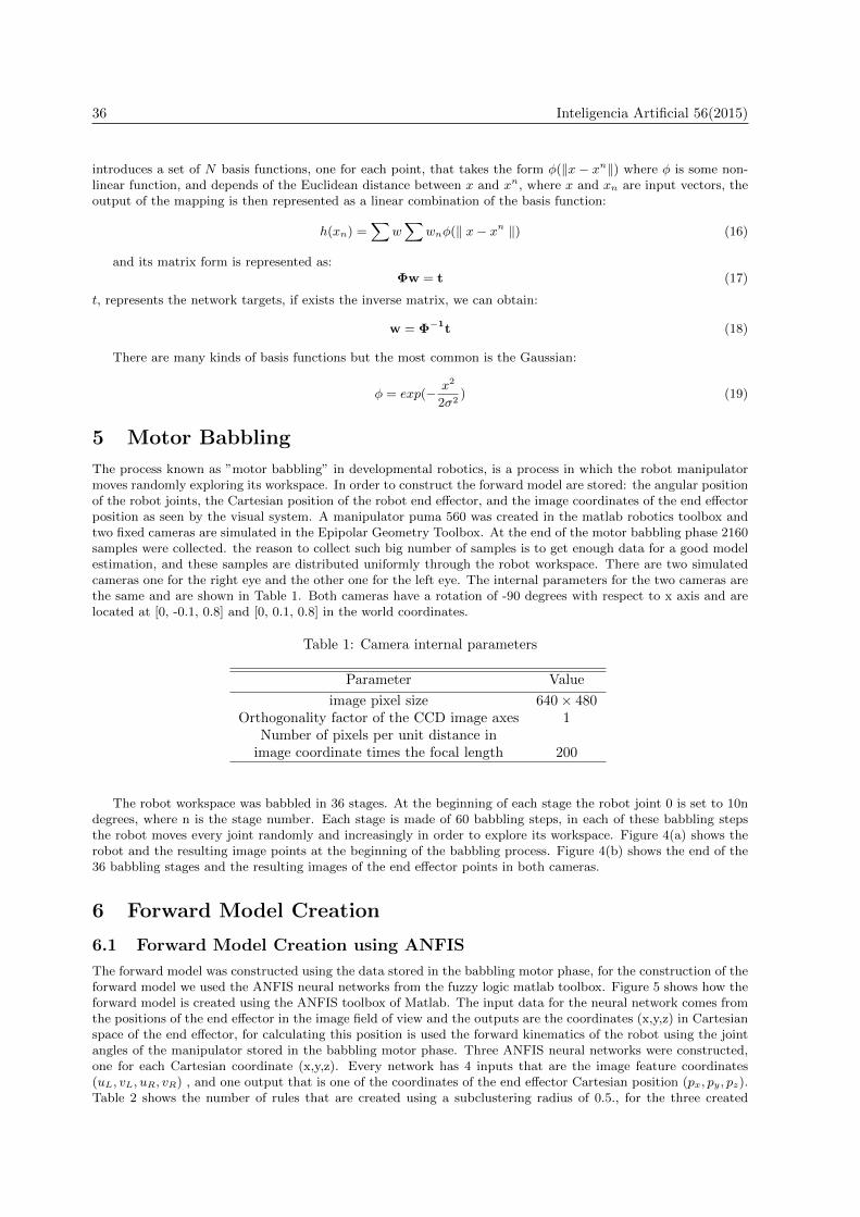
introduces a set of N basis functions, one for each point, that takes the form φ(‖x− xn‖) where φ is some non-linear function, and depends of the Euclidean distance between x and xn, where x and xn are input vectors, theoutput of the mapping is then represented as a linear combination of the basis function:
h(xn) =∑
w∑
wnφ(‖ x− xn ‖) (16)
and its matrix form is represented as:
Φw = t (17)
t, represents the network targets, if exists the inverse matrix, we can obtain:
w = Φ−1t (18)
There are many kinds of basis functions but the most common is the Gaussian:
φ = exp(− x2
2σ2) (19)
5 Motor Babbling
The process known as ”motor babbling” in developmental robotics, is a process in which the robot manipulatormoves randomly exploring its workspace. In order to construct the forward model are stored: the angular positionof the robot joints, the Cartesian position of the robot end effector, and the image coordinates of the end effectorposition as seen by the visual system. A manipulator puma 560 was created in the matlab robotics toolbox andtwo fixed cameras are simulated in the Epipolar Geometry Toolbox. At the end of the motor babbling phase 2160samples were collected. the reason to collect such big number of samples is to get enough data for a good modelestimation, and these samples are distributed uniformly through the robot workspace. There are two simulatedcameras one for the right eye and the other one for the left eye. The internal parameters for the two cameras arethe same and are shown in Table 1. Both cameras have a rotation of -90 degrees with respect to x axis and arelocated at [0, -0.1, 0.8] and [0, 0.1, 0.8] in the world coordinates.
Table 1: Camera internal parameters
Parameter Value
image pixel size 640 × 480Orthogonality factor of the CCD image axes 1
Number of pixels per unit distance inimage coordinate times the focal length 200
The robot workspace was babbled in 36 stages. At the beginning of each stage the robot joint 0 is set to 10ndegrees, where n is the stage number. Each stage is made of 60 babbling steps, in each of these babbling stepsthe robot moves every joint randomly and increasingly in order to explore its workspace. Figure 4(a) shows therobot and the resulting image points at the beginning of the babbling process. Figure 4(b) shows the end of the36 babbling stages and the resulting images of the end effector points in both cameras.
6 Forward Model Creation
6.1 Forward Model Creation using ANFIS
The forward model was constructed using the data stored in the babbling motor phase, for the construction of theforward model we used the ANFIS neural networks from the fuzzy logic matlab toolbox. Figure 5 shows how theforward model is created using the ANFIS toolbox of Matlab. The input data for the neural network comes fromthe positions of the end effector in the image field of view and the outputs are the coordinates (x,y,z) in Cartesianspace of the end effector, for calculating this position is used the forward kinematics of the robot using the jointangles of the manipulator stored in the babbling motor phase. Three ANFIS neural networks were constructed,one for each Cartesian coordinate (x,y,z). Every network has 4 inputs that are the image feature coordinates(uL, vL, uR, vR) , and one output that is one of the coordinates of the end effector Cartesian position (px, py, pz).Table 2 shows the number of rules that are created using a subclustering radius of 0.5., for the three created

Inteligencia Artificial 56(2015) 37
(a) (b)
Figure 4: Babbling motor. (a) The left subplot shows the position of the robot after the second babblingstage (joint 0 is initialized to 20 degrees). The top and bottom subplots show the imaged end effectorpoints at each babbling step. (b) The left subplot shows the position of the robot at the end of thebabbling. The right top and right bottom subplots are the end effector accumulated positions of the endeffector in the right and left camera.
Table 2: ANFIS Initialization
Neural Network Subclustering radius Number of rules
ANFIS 1(x) 0.5 6ANFIS 2(y) 0.5 8ANFIS 3(z) 0.5 10
neural networks. Analytical methods could be used also to construct the model proposed in this work, but theyneed a calibration step and know the internal and external camera parameters, the process of constructing thatmodel could be prone to error if the parameters are not well estimated, besides a distortion correction phase isnecessary once the model has been constructed.
6.2 Forward Model Creation using MLP and RBF
Using the same data stored in the babbling motor phase it was constructed the forward model employing multilayerperceptron neural networks. So, three networks were created with the same inputs and outputs that were used forthe ANFIS networks, before the training phase the data was preprocessed in the intervals of 1 and -1, 10 neuronswere used in the hidden layer of every network; the number of epochs during the training phase of every networkwere 150, 33, 69 respectively.
Furthermore, the data created in the babbling motor phase was also used for constructing the radial basisfunctions networks, after preprocessing the data 3 neural networks were created with the following trainingparameters , sum squared error set as 0.06 for the three networks, and spread constant defined as 0.75, 0.9 and0.6 respectively for the three RBF neural networks.
7 Reaching Following a Moving Target
7.1 Piepmeir’s Algorithm for Following a Moving Target
Initially, the robot is in the position defined in joint coordinates as [-1.4, -0.3, -1.47, 0, 0, 0], the final objective isthat the robot could follow a simulated moving target defined by the equations:
x = x0 + 0.2 ∗ sin(wt)y = y0 + 0.1 ∗ cos(wt) (20)
The initial position of the target in Cartesian space is with w = 0.01, x0 = 0.25, y0 = 0.2 and z0 = 0.4. For thesimulations, the camera frame rate for this simulation is fixed at 1/60 sec. The simulation time step is 0.005. The

38 Inteligencia Artificial 56(2015)
Figure 5: Construction of the forward model using an ANFIS based methodology.
number of iterations for the control loop is equal to 800 control steps (iterations).
Figure 6(a), shows the trajectory of the moving target (continuous line) and the trajectory followed by theend effector (cross marks) in the cameras image field of view; furthermore, figure 6(b) shows the trajectory of theend effector traversed in the 3D space. Figure 7, shows the error of the visual servoing controller following themoving target. This error is a normalized error that estimates in each iteration the difference between the desiredimage position and the actual position.
(a) (b)
Figure 6: Figure 6. End effector trajectories using Piepmeir’s algorithm. (a) Trajectories followed by thetarget (green) and robot end effector (red) in the image field of view of the two cameras using Piepmeir’salgorithm. (b) 3D Trajectory of the end effector using the Piepmeir’s algorithm.
7.2 Proposed Architecture for Following a Moving Target Using ANFIS
The final objective of the robot is that it could follow a moving target trajectory on its workspace. So, first therobot employs the forward model encoded in the ANFIS neural networks to calculate the Cartesian position ofthe moving target, this position is used as the desired position to be reached for the Cartesian controller. Inthe experiments the initial position of the robot is also [-1.4, -0.3, -1.47, 0, 0, 0] in joint coordinates. The joint

Inteligencia Artificial 56(2015) 39
Figure 7: Visual servoing controller error for following a moving target.
(a) (b)
Figure 8: End effector trajectories using ANFIS. (a) Trajectories followed by the target (green) and robotend effector (red) in the image field of view of the two cameras using the proposed architecture basedin forward models and a Cartesian controller. (b) 3D Trajectory of the end effector using the proposedarchitecture based on forward models.
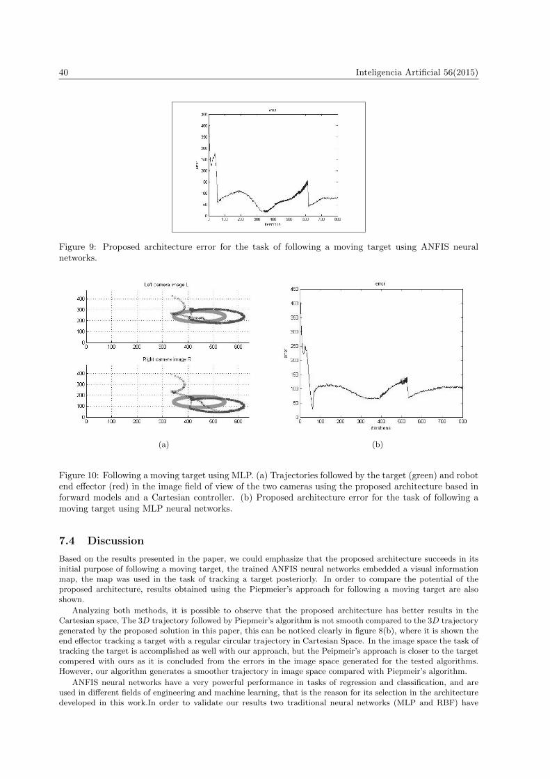
velocities fixed in the experiments are six times the velocities used with the Piepmeier's approach, we tried thesame velocities with the Piepemeier's algorithm, but just doubling the velocities in the joints will generate worseresults. Figure 8(a), shows the trajectories followed in the image field of view for the target (continuous line) andthe end effector position (cross marks). Figure 8(b) shows the traversed trajectory of the end effector in threedimensional space. Figure 9 shows the error obtained with the proposed architecture. This error in image spaceis the same defined for the experiments with the Piepmeiers's approach.
7.3 Proposed Architecture for Following a Moving Target Using MLP andRBF
Figure 10 shows the results of the proposed architecture in this paper using MLP networks, figure 10(a) showsthe image trajectory of the end effector and figure 10(b) shows the error obtained with the controller.
Furtheremore, Figure 11, shows the results using forward models with RBF networks, figure 11(a) shows theimage trajectory of the end effector and figure 11(b) shows the error obtained with the controller.
40 Inteligencia Artificial 56(2015)
Figure 9: Proposed architecture error for the task of following a moving target using ANFIS neuralnetworks.
(a) (b)
Figure 10: Following a moving target using MLP. (a) Trajectories followed by the target (green) and robotend effector (red) in the image field of view of the two cameras using the proposed architecture based inforward models and a Cartesian controller. (b) Proposed architecture error for the task of following amoving target using MLP neural networks.
7.4 Discussion
Based on the results presented in the paper, we could emphasize that the proposed architecture succeeds in itsinitial purpose of following a moving target, the trained ANFIS neural networks embedded a visual informationmap, the map was used in the task of tracking a target posteriorly. In order to compare the potential of theproposed architecture, results obtained using the Piepmeier’s approach for following a moving target are alsoshown.
Analyzing both methods, it is possible to observe that the proposed architecture has better results in theCartesian space, The 3D trajectory followed by Piepmeir’s algorithm is not smooth compared to the 3D trajectorygenerated by the proposed solution in this paper, this can be noticed clearly in figure 8(b), where it is shown theend effector tracking a target with a regular circular trajectory in Cartesian Space. In the image space the task oftracking the target is accomplished as well with our approach, but the Peipmeir’s approach is closer to the targetcompered with ours as it is concluded from the errors in the image space generated for the tested algorithms.However, our algorithm generates a smoother trajectory in image space compared with Piepmeir’s algorithm.
ANFIS neural networks have a very powerful performance in tasks of regression and classification, and areused in different fields of engineering and machine learning, that is the reason for its selection in the architecturedeveloped in this work.In order to validate our results two traditional neural networks (MLP and RBF) have

Inteligencia Artificial 56(2015) 41
(a) (b)
Figure 11: Following a moving target using RBF. (a) Trajectories followed by the target (green) and robotend effector (red) in the image field of view of the two cameras using the proposed architecture based inforward models and a Cartesian controller. (b) Proposed architecture error for the task of following amoving target using RBF neural networks.
also been tested. So, we repeated the experiments using forward models embedded in RBF and MLP neuralnetworks and the results are very similar to the ANFIS performance, just RBF had a little better performance inimage space compared with the other networks. Future applications of the control architecture proposed couldbe visualized as a controller for a manipulator used in rehabilitation robotics that could be used for patients thatsuffered a stroke in order to recover their motor capabilities guided by the robot; another application could bevisualized as a manipulator for a welding task in order to track a trajectory.
8 Conclusion
The main discernible contributions proposed by the paper are a new application of a forward model for followinga moving target task using a Cartesian controller with image processing feedback with a robot manipulator.Another paper contribution is the proposal of a new control architecture for the task of tracking a movingtarget, an architecture that is founded in the developmental robotics field using past information embedded inANFIS neural networks obtained during a babbling motor phase to accomplish the task of following a target, ourarchitecture is able to generalize a new information based in past experiences (”motor babbling”) and is morebiological plausible. In order to show the applicability of our approach we also constructed forward models usingMLP and RBF neural networks, obtaining very similar results to ANFIS networks. Finally, our last contributionis the comparison of two approaches for solving the problem of tracking a moving target with a robot manipulator;as a result of the comparison, we could state that we have a better performance in the Cartesian space and anacceptable performance in the image space for the tracking with the approach proposed in this paper comparedwith the Piepmeier’s approach.
Acknowledgements
We would like to thank to the reviewers for their comments that helped to improve the paper.
References
[1] B.M. Becerra, S. Cook, and J. Deng. Predicted computer torque control of a puma 560 manipulator robot.In IFAC World Congress-Internantional Federation of Automatic Control, 2005.
[2] C. Bishop. Neural networks for pattern recognition. Evolutionary Computation, 10:99–127, 2002.

42 Inteligencia Artificial 56(2015)
[3] P.I. Corke. A robotic toolbox for matlab. IEEE in Robotics and Automation Magazine, 3:24–32, 1996.
[4] Jhon J. Craig. Introduction to Robotics, Mechatronics and Control. Pearson Prentice Hall.
[5] D.F.T. Gamarra. Forward models with cluster validity criteria applied in ballistic reaching for visual servoing.International Review on Modelling and simulations, 6:1939–1947, 2013.
[6] D.F.T. Gamarra, L.K.Pinpin, C. Laschi, and P. Dario. Forward models applied in visual servoing for areaching task in the icub humanoid robot. Applied Bionics and Biomechanics, 6:345–354, 2009.
[7] S. Hutchinson, E.D. Hager, and P.I. Corke. A tutorial on visual servo control. IEEE Transactions on Roboticsand Auromation, 12:651–670, 1996.
[8] J.S.R. Jang and C.T. Sun. Neuro-fuzzy modeling and control. Proc. of the IEEE, 83:378–406, 1995.
[9] J.A.Piepmeier, G.V. McMurray, and H. Linkin. A dynamic jacobian estimation method for uncalibratedvisual servoing. In Proc. of the IEEE International Conference on Advance Mechatronics (ASME), pages944–949, 1999.
[10] J.A.Piepmeier, G.V. McMurray, A. Pfeiffer, and H. Linkin. Uncalibrated target tracking with obstacleavoidance. In Proc. of the IEEE International Conference on Robotics and Automation (ICRA), pages 1670–1675, 1999.
[11] M. Kawato. Internal models for motor control and trajectory planning. Trends in Cognitive Science, 9:718–727, 1999.
[12] L.K.Pinpin, D.F.T. Gamarra, C. Laschi, and P. Dario. Forward model creation for visual servoing in a sixlink manipulator. In Proc. of the IEEE Conference on Biomedical Robotics and Biomechatronics (BIOROB),2008.
[13] G.L. Mariottini and D. Prattichizzo. A robotic toolbox for matlab. EGT for multiple view and visual servoing:robotics vision with pinhole and panoramic cameras, 12:26–39, 2005.
[14] L. Natale, F. Nori, G. Metta, M. Fumagaldi, S. Ivaldi, U. Pattacini, M. Randazzo, A. Schmitz, and L. San-dini. Intrinsically motivated learning in natural and artificial systems, chapter The iCub platform a tool forstudying intrinsically motivated learning. Baldassarre, Gianluca and Miroli, 2012.
[15] F. Nori, G. Metta, and L. Sandini. Robust Intelligent Systems, chapter Exploiting motor modules in modularcontext. Alfons Schuster, 2008.
[16] R. Saegusa, G. Metta, and L. Sandini. Body definition based on visuomotor correlation. IEEE Transactionson Industrial Engineering, 59.
[17] P. Sanchez-Sanchez and F. Reyes-Cortes. A new cartesian controller for robot manipulators. In Proc. of theIEEE International Conference on Intelligent Robotics and Systems (IROS), pages 2059–2064, 2005.
[18] B. Siciliano, L. Sciavicco, L. Villani, and G. Oriolo. Robotics, Modelling, Planning and Control. Springer,London-UK, 2009.
[19] E. Tellen, D. Corbetta, K. Kamm, J.P. Spencer, K. Schneider, and R.F. Zernicke. The transition to reaching:Mapping intention and intrinsic dynamics. Child Development, 64:1058–1098, 1993.
[20] M.H. Terra and R. Tinos. Fault detection and isolation of robotic systems using a multilayer perceptron anda radial basis function. In Proc. of the IEEE International Conference on Systems, Man and Cybernetics,pages 1880–1885, 1998.
[21] C. von Hofsten. Eye-hand coordination in the newborn. Developmental Psychology, 18:450–461, 1982.
[22] J.A. Walter and K.J. Shulten. Implementation of self-organizing neural networks for visuo-motor control ofan industrial robot. IEEE Transactions on Neural Networks, 59:86–95, 1993.
[23] D. M. Wolpert, R.C. Miall, and M. Kawato. Internal models in cerebellum. Trends in Cognitive Science,2:338–347, 1998.