Intel Stratix 10 SoC UEFI Boot Loader User Guide · 2020-05-31 · To load and execute the Intel...
19
Intel Stratix 10 SoC UEFI Boot Loader User Guide Subscribe Send Feedback UG-20080 | 2019.03.28 Latest document on the web: PDF | HTML
Transcript of Intel Stratix 10 SoC UEFI Boot Loader User Guide · 2020-05-31 · To load and execute the Intel...
Intel Stratix 10 SoC UEFI BootLoader User Guide
SubscribeSend Feedback
UG-20080 | 2019.03.28Latest document on the web: PDF | HTML

Contents
1. Boot Flow Overview........................................................................................................ 3
2. System Requirements..................................................................................................... 52.1. Minimum Hardware Requirements............................................................................52.2. Minimum Software Requirements.............................................................................52.3. Optional Virtual Platforms....................................................................................... 5
3. Getting Started............................................................................................................... 63.1. Installing Software Components.............................................................................. 6
3.1.1. Installing the Intel SoC EDS........................................................................ 63.1.2. Installing the Compiler Toolchain................................................................. 6
3.2. Building the Secure Monitor.................................................................................... 63.2.1. User Configuration..................................................................................... 73.2.2. Getting the Arm Trusted Firmware Source Code............................................. 73.2.3. Building the BL31 image............................................................................. 8
3.3. Building the UEFI Boot Loader................................................................................. 93.3.1. Prerequisites.............................................................................................93.3.2. Obtaining the UEFI Source Code................................................................ 103.3.3. Compiling the UEFI Source Code with the Linaro Tool Chain........................... 103.3.4. UEFI Generated Files................................................................................ 12
4. Running UEFI on Intel Stratix 10 Hardware.................................................................. 134.1. Running on a Physical Board with ATF and UEFI Bootloader....................................... 13
4.1.1. Generate a .sof file with ATF......................................................................134.1.2. Creating an SD Card Image with PEI.ROM and DXE.ROM...............................134.1.3. Running the Secure Monitor...................................................................... 144.1.4. Debugging with DS-5............................................................................... 14
4.2. Booting Linux...................................................................................................... 174.2.1. Booting from the DXE Console................................................................... 18
5. Document Revision History for Intel Stratix 10 SoC UEFI Boot Loader User Guide........19
Contents
Intel Stratix 10 SoC UEFI Boot Loader User Guide Send Feedback
2
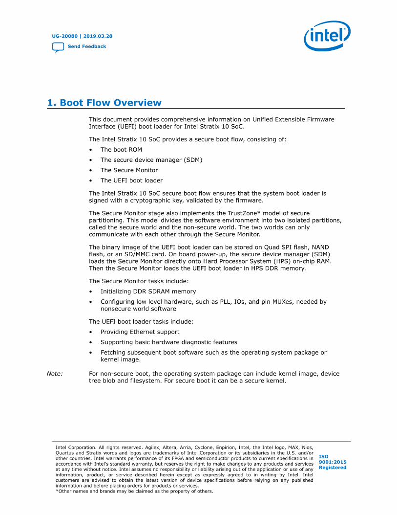
1. Boot Flow OverviewThis document provides comprehensive information on Unified Extensible FirmwareInterface (UEFI) boot loader for Intel Stratix 10 SoC.
The Intel Stratix 10 SoC provides a secure boot flow, consisting of:
• The boot ROM
• The secure device manager (SDM)
• The Secure Monitor
• The UEFI boot loader
The Intel Stratix 10 SoC secure boot flow ensures that the system boot loader issigned with a cryptographic key, validated by the firmware.
The Secure Monitor stage also implements the TrustZone* model of securepartitioning. This model divides the software environment into two isolated partitions,called the secure world and the non-secure world. The two worlds can onlycommunicate with each other through the Secure Monitor.
The binary image of the UEFI boot loader can be stored on Quad SPI flash, NANDflash, or an SD/MMC card. On board power-up, the secure device manager (SDM)loads the Secure Monitor directly onto Hard Processor System (HPS) on-chip RAM.Then the Secure Monitor loads the UEFI boot loader in HPS DDR memory.
The Secure Monitor tasks include:
• Initializing DDR SDRAM memory
• Configuring low level hardware, such as PLL, IOs, and pin MUXes, needed bynonsecure world software
The UEFI boot loader tasks include:
• Providing Ethernet support
• Supporting basic hardware diagnostic features
• Fetching subsequent boot software such as the operating system package orkernel image.
Note: For non-secure boot, the operating system package can include kernel image, devicetree blob and filesystem. For secure boot it can be a secure kernel.
UG-20080 | 2019.03.28
Send Feedback
Intel Corporation. All rights reserved. Agilex, Altera, Arria, Cyclone, Enpirion, Intel, the Intel logo, MAX, Nios,Quartus and Stratix words and logos are trademarks of Intel Corporation or its subsidiaries in the U.S. and/orother countries. Intel warrants performance of its FPGA and semiconductor products to current specifications inaccordance with Intel's standard warranty, but reserves the right to make changes to any products and servicesat any time without notice. Intel assumes no responsibility or liability arising out of the application or use of anyinformation, product, or service described herein except as expressly agreed to in writing by Intel. Intelcustomers are advised to obtain the latest version of device specifications before relying on any publishedinformation and before placing orders for products or services.*Other names and brands may be claimed as the property of others.
ISO9001:2015Registered
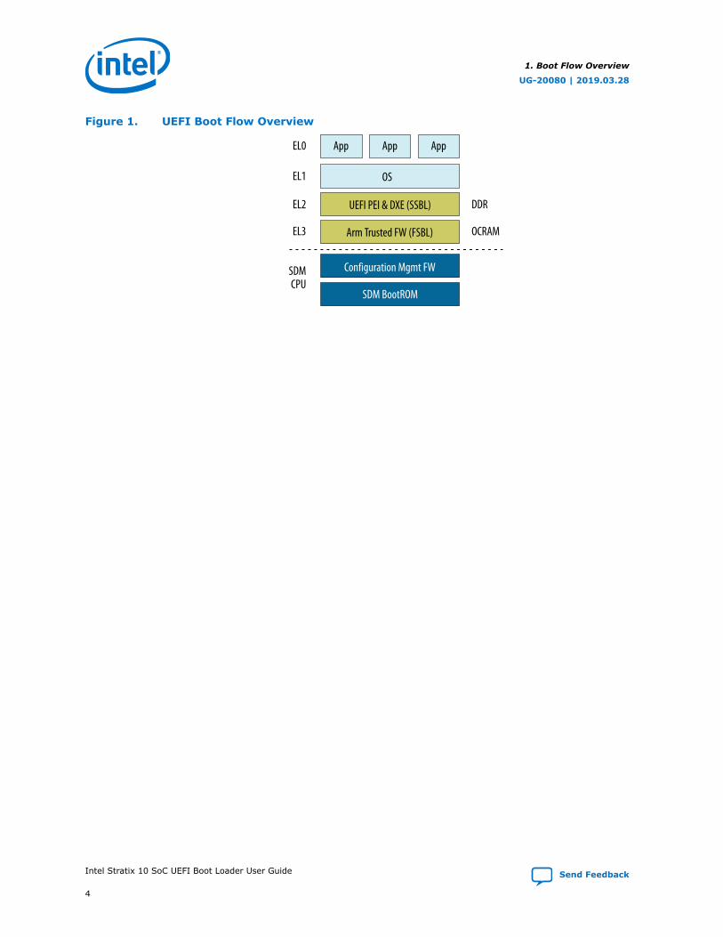
Figure 1. UEFI Boot Flow Overview
App App
OS
UEFI PEI & DXE (SSBL)
Arm Trusted FW (FSBL)
Configuration Mgmt FW
SDM BootROM
SDMCPU
EL3
EL2 DDR
OCRAM
EL1
EL0 App
1. Boot Flow Overview
UG-20080 | 2019.03.28
Intel Stratix 10 SoC UEFI Boot Loader User Guide Send Feedback
4
2. System RequirementsTo load and execute the Intel Stratix 10 SoC Unified Extensible Firmware Interface(UEFI) boot loader, your system must meet the following requirements.
2.1. Minimum Hardware Requirements
• Windows PC or Linux workstation with the following configuration:
— Serial terminal, such as Minicom for Linux or Tera Tem for Windows
— microSD card slot or microSD card writer or SD capable writer with SD tomicroSD converter
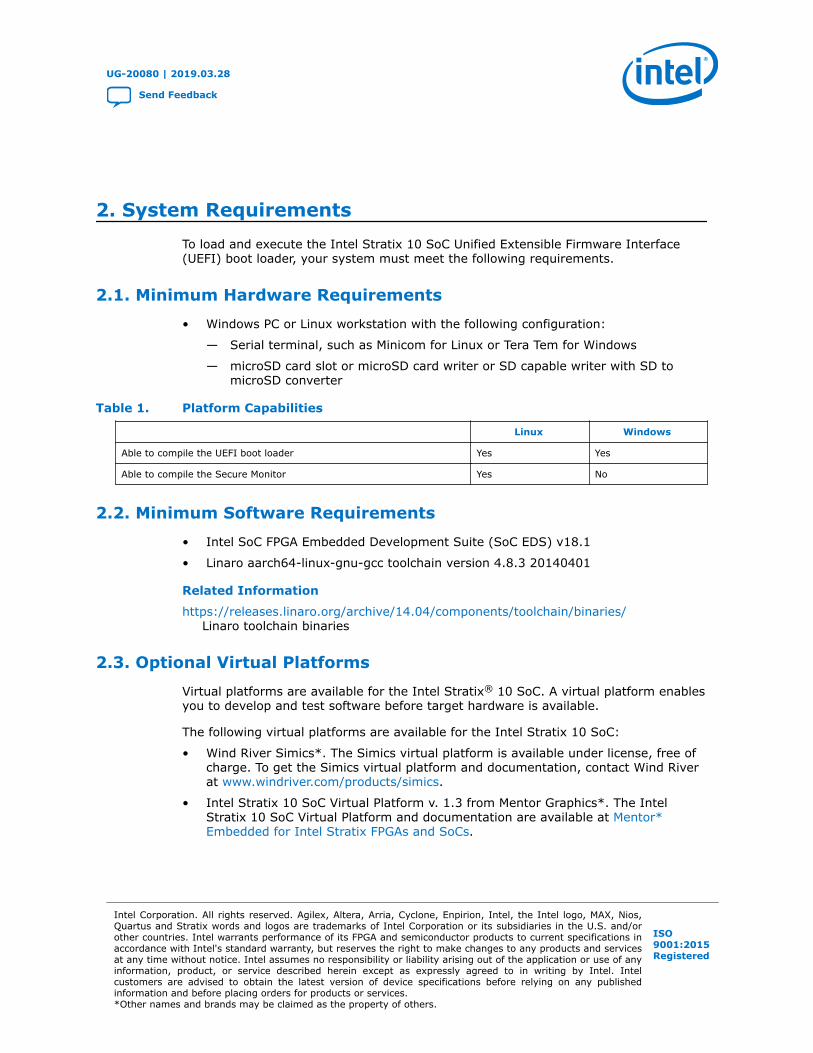
Table 1. Platform Capabilities
Linux Windows
Able to compile the UEFI boot loader Yes Yes
Able to compile the Secure Monitor Yes No
2.2. Minimum Software Requirements
• Intel SoC FPGA Embedded Development Suite (SoC EDS) v18.1
• Linaro aarch64-linux-gnu-gcc toolchain version 4.8.3 20140401
Related Information
https://releases.linaro.org/archive/14.04/components/toolchain/binaries/Linaro toolchain binaries
2.3. Optional Virtual Platforms
Virtual platforms are available for the Intel Stratix® 10 SoC. A virtual platform enablesyou to develop and test software before target hardware is available.
The following virtual platforms are available for the Intel Stratix 10 SoC:
• Wind River Simics*. The Simics virtual platform is available under license, free ofcharge. To get the Simics virtual platform and documentation, contact Wind Riverat www.windriver.com/products/simics.
• Intel Stratix 10 SoC Virtual Platform v. 1.3 from Mentor Graphics*. The IntelStratix 10 SoC Virtual Platform and documentation are available at Mentor*Embedded for Intel Stratix FPGAs and SoCs.
UG-20080 | 2019.03.28
Send Feedback
Intel Corporation. All rights reserved. Agilex, Altera, Arria, Cyclone, Enpirion, Intel, the Intel logo, MAX, Nios,Quartus and Stratix words and logos are trademarks of Intel Corporation or its subsidiaries in the U.S. and/orother countries. Intel warrants performance of its FPGA and semiconductor products to current specifications inaccordance with Intel's standard warranty, but reserves the right to make changes to any products and servicesat any time without notice. Intel assumes no responsibility or liability arising out of the application or use of anyinformation, product, or service described herein except as expressly agreed to in writing by Intel. Intelcustomers are advised to obtain the latest version of device specifications before relying on any publishedinformation and before placing orders for products or services.*Other names and brands may be claimed as the property of others.
ISO9001:2015Registered

3. Getting Started
3.1. Installing Software Components
3.1.1. Installing the Intel SoC EDS
You must install the Intel SoC EDS v18.1 on your machine.
Download the SoC EDS from the Download Center for FPGAs.
3.1.2. Installing the Compiler Toolchain
You compile the UEFI boot loader and the Secure Monitor with the GNU Toolchain(EABI Release) for Arm* Processors.
The supported compiler toolchain is Linaro* aarch64-linux-gnu-gcc (crosstool-NGlinaro-1.13.1-4.8-2014.04 - Linaro GCC 4.8-2014.04) 4.8.3 20140401 (prerelease).You can download the toolchain from https://releases.linaro.org/archive/14.04/components/toolchain/binaries/.
• Linux: gcc-linaro-aarch64-linux-gnu-4.8-2014.04_linux.tar
• Windows: gcc-linaro-aarch64-linux-gnu-4.8-2014.04_win32.zip
Related Information
https://releases.linaro.org/archive/14.04/components/toolchain/binaries/Linaro toolchain downloads
3.2. Building the Secure Monitor
As security becomes more and more important, a secured boot solution becomes arequirement in the embedded world. To ensure comprehensive security and a trustedplatform, secure partitioning is required. The Intel Stratix 10 device achieves securepartitioning by implementing the TrustZone model with Arm Trusted Firmware (ATF).The TrustZone model splits the computing environment into two isolated worlds, thesecure world and normal world, which are linked by a software monitor called theSecure Monitor. The two worlds have separated logical address space and peripherals.Communication between the two worlds is only possible by calling the privilegedSecure Monitor call (SMC) instruction.
The full secure boot solution is:
• BootRom
• Secure Device Manager
• Secure Monitor
UG-20080 | 2019.03.28
Send Feedback
Intel Corporation. All rights reserved. Agilex, Altera, Arria, Cyclone, Enpirion, Intel, the Intel logo, MAX, Nios,Quartus and Stratix words and logos are trademarks of Intel Corporation or its subsidiaries in the U.S. and/orother countries. Intel warrants performance of its FPGA and semiconductor products to current specifications inaccordance with Intel's standard warranty, but reserves the right to make changes to any products and servicesat any time without notice. Intel assumes no responsibility or liability arising out of the application or use of anyinformation, product, or service described herein except as expressly agreed to in writing by Intel. Intelcustomers are advised to obtain the latest version of device specifications before relying on any publishedinformation and before placing orders for products or services.*Other names and brands may be claimed as the property of others.
ISO9001:2015Registered

• Uboot/UEFI
• Hypervisor
• OS
Secure Monitor mode is a privileged mode and is always secure regardless of the stateof the NS bit. The Secure Monitor is code that runs in Secure Monitor mode andprocesses switches to and from the Secure world. The overall security of the softwarerelies on the security of this code along with the Secure boot code.
Related Information
www.trustedfirmware.orgGeneral information about Arm Trusted Firmware
3.2.1. User Configuration
You can find all platform configurations in arm-trusted-firmware/plat/intel/soc/stratix10/platform_def.h.
For user configuration, you should only modify the first part of this file.
/**********************************************************************User configuration*********************************************************************///#define EMULATOR//#define VIRTUAL_PLATFORM#define ENABLE_HANDOFF#define PLAT_SEMIHOSTING_ENABLE#define PLAT_NS_IMAGE_OFFSET 0x50000#define PLAT_HANDOFF_OFFSET 0xFFE3F000#define BOOT_SOURCE BOOT_SOURCE_SDMMC
Note: To change the boot filename or offset, you can change the #define in this file.
3.2.2. Getting the Arm Trusted Firmware Source Code
The ATF source is at https://github.com/altera-opensource/arm-trusted-firmware. Toget the ATF source code, simply run the following steps:
1. Open a terminal.
2. Create a new directory to check out the ATF source code from GitHub.
3. Change to this working directory and clone the ATF source from the Git trees asfollows:
$ git clone https://github.com/altera-opensource/arm-trusted-firmware
4. When completed, change to the arm-trusted-firmware folder and perform aGit check out as follows:
$ cd arm-trusted-firmware$ git checkout -t -b test_atf origin/socfpga_v1.4
Related Information
• Building the BL31 image on page 8
• Compiling the UEFI Source Code with the Linaro Tool Chain on page 10
3. Getting Started
UG-20080 | 2019.03.28
Send Feedback Intel Stratix 10 SoC UEFI Boot Loader User Guide
7
• Running the Secure Monitor on page 14
• https://github.com/altera-opensource/arm-trusted-firmware
3.2.3. Building the BL31 image
This section describes how to build the ATF with the Linaro GCC compiler.
To start building the ATF with the Linaro GCC compiler, simply run the following steps:
1. Change your directory to the ATF source code location as follows:
$ cd arm-trusted-firmware
2. Set the GCC path and environment variable CROSS_COMPILE to Linaro crosscompile as follows:
$ export PATH=<your gcc directory>/\gcc-linaro-aarch64-linux-gnu-4.8-2014.04_linux/bin:$PATH$ export CROSS_COMPILE=aarch64-linux-gnu-
3. Remove the build tree completely as follows:
$ make realclean
4. Build the ATF by using the following command:
$ make PLAT=stratix10 DEBUG=1
Note: You must enable debugging GCC 4.8. You can disable debugging for GCC4.9 and above.
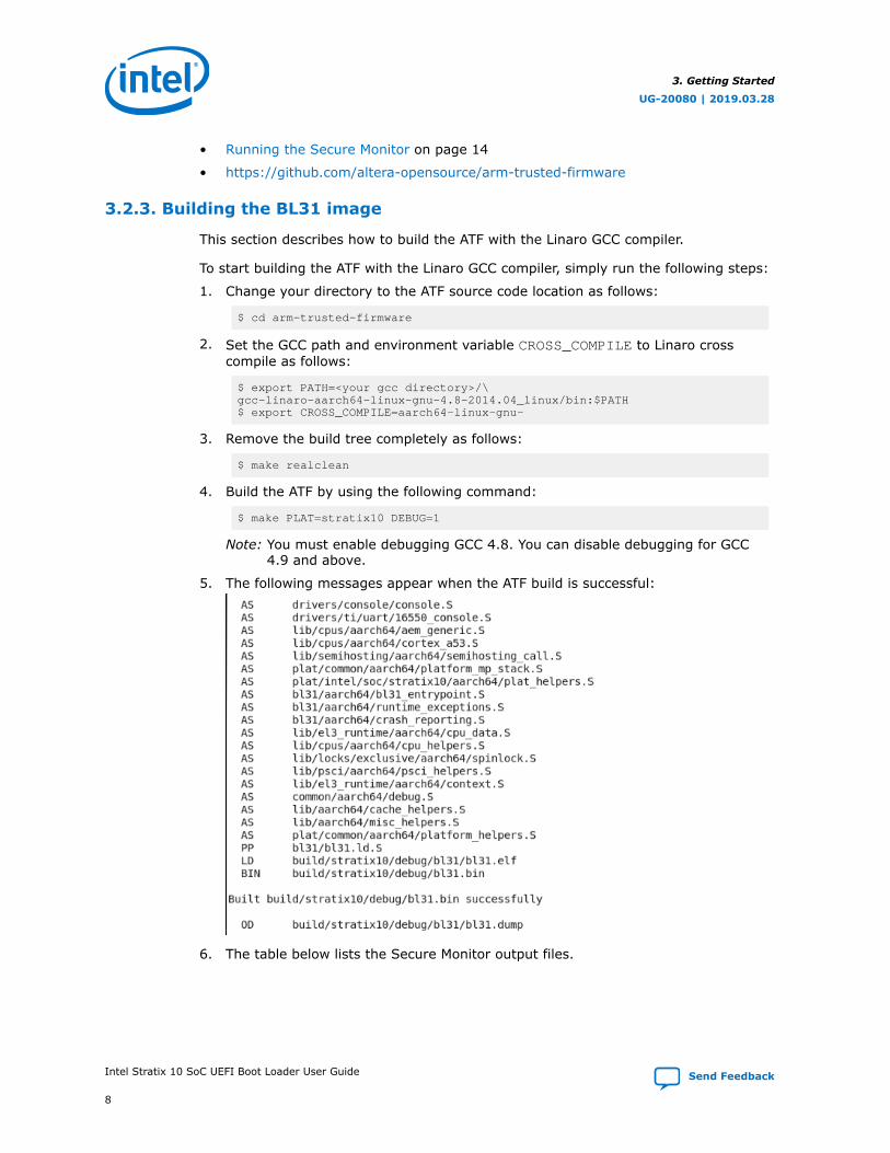
5. The following messages appear when the ATF build is successful:
6. The table below lists the Secure Monitor output files.
3. Getting Started
UG-20080 | 2019.03.28
Intel Stratix 10 SoC UEFI Boot Loader User Guide Send Feedback
8

Table 2. Descriptions of Secure Monitor Files
File Path and Name Description
\build\stratix10\release\bl31.bin Generated binary file
\build\stratix10\release\bl31\bl31.elf Generated elf file
\build\stratix10\debug\bl31.bin Generated debug binary file
\build\stratix10\debug\bl31\bl31.elf Generated debug elf file
Note: The first two files in the table above are generated if you run make PLAT=stratix10without the DEBUG option.
3.3. Building the UEFI Boot Loader
To build a UEFI boot loader, you obtain the UEFI source code and compile the UEFIsource with the supported toolchain.
The Unified Extensible Firmware Interface (UEFI) is a standardized firmwarespecification that simplifies and secures platform initialization and firmware bootstrapoperations. UEFI is currently developed and supported by representatives from morethan 250 industry-leading technology companies. Arm and the Linaro Enterprise Groupare also promoting the use of UEFI on Arm architecture, because the UEFIspecification helps standardize the boot process for Arm processor-based platforms.
UEFI technology is future-proofed through standardization of firmware design ratherthan proprietary firmware design. UEFI specifications promote business andtechnological efficiency, improve performance and security, facilitate interoperabilitybetween devices, platforms and systems and comply with next-generationtechnologies. The UEFI specification is peer-reviewed and published, allowingdevelopers to write firmware once per platform and reuse it without muchmodification. This reuse results in cost and time savings during boot loaderdevelopment.
This framework uses the BSD license, permitting you to optionally commercialize yourimplementation with minimal legal issues.
You can compile the UEFI source code either in a Windows or in a Linux system.
3.3.1. Prerequisites
For Windows System
If you are using a Windows system, you must have Git installed. You can download Gitfrom www.git-scm.com/download/win.
For Linux System
Building the UEFI requires additional Linux packages. Depending on your Linuxdistribution, the command to install the packages is different:
If you are using a Ubuntu distribution, type:
$ sudo apt-get install uuid-dev build-essential
3. Getting Started
UG-20080 | 2019.03.28
Send Feedback Intel Stratix 10 SoC UEFI Boot Loader User Guide
9
If you using a Fedora distribution, type:
$ sudo yum install uuid-devel libuuid-devel
For building UEFI, the Python package is required. If Python is not already available onyour system, running the commands from the SoC EDS Embedded Command Shellprovides the required Python dependency.
3.3.2. Obtaining the UEFI Source Code
The UEFI source code is located in GitHub. The following steps show you how to getthe UEFI source code.
1. Open a terminal.
2. Clone the UEFI source from the Git trees.
$ git clone https://github.com/altera-opensource/uefi-socfpga
3. When completed, change to the uefi-socfpga folder and perform a Git checkout.
$ cd uefi-socfpga $ git checkout -t -b test_uefi origin/socvp_socfpga_udk2015
3.3.3. Compiling the UEFI Source Code with the Linaro Tool Chain
3.3.3.1. Windows System
To compile the UEFI source code with the Linaro toolchain in a Windows system:
1. Open the command prompt.
2. Go to your working directory and set SOCEDS_DEST_ROOT to the location of yourSoC EDS.
$ cd <your_working_directory>\uefi-socfpga$ set SOCEDS_DEST_ROOT=<your_SOCEDS_location>
3. Set the GCC path to the location of the compiler toolchain.
$ set PATH=<your_Linaro GCC Toolchain_location>;%PATH%
Note: If you encountered a GCC error while compiling the UEFI source code aftersetting the path, you can edit the setup.bat file manually by entering thefollowing command to use the full compiler path.
set GCC48_ARM_PREFIX=%DS5_ROOT%\sw\gcc\bin\arm-linux-gnueabihf-set GCC48_AARCH64_PREFIX=<your working directory>\uefi_17v0_window\gcc-linaro-aarch64-linux-gnu-4.8-2014.04_win32\bin\aarch64-linux-gnu-
4. Run the setup command.
$ setup.bat
5. Build the UEFI by entering the following command:
$ make device=s10
3. Getting Started
UG-20080 | 2019.03.28
Intel Stratix 10 SoC UEFI Boot Loader User Guide Send Feedback
10
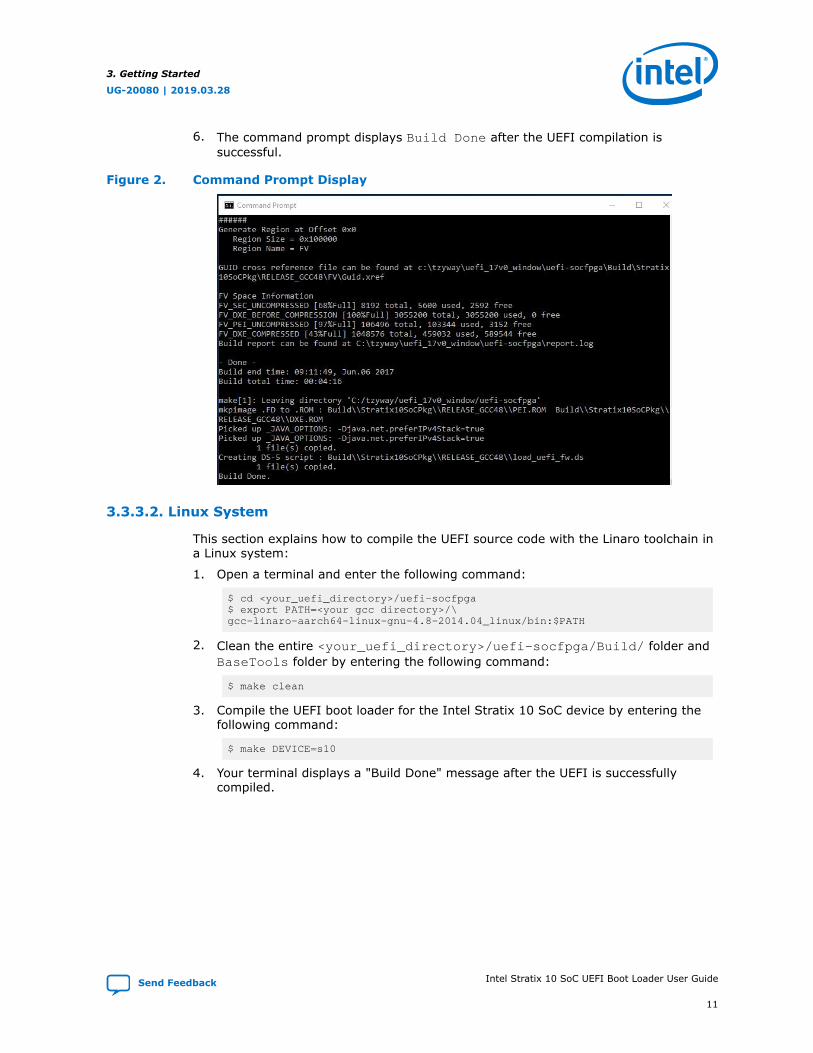
6. The command prompt displays Build Done after the UEFI compilation issuccessful.
Figure 2. Command Prompt Display
3.3.3.2. Linux System
This section explains how to compile the UEFI source code with the Linaro toolchain ina Linux system:
1. Open a terminal and enter the following command:
$ cd <your_uefi_directory>/uefi-socfpga$ export PATH=<your gcc directory>/\gcc-linaro-aarch64-linux-gnu-4.8-2014.04_linux/bin:$PATH
2. Clean the entire <your_uefi_directory>/uefi-socfpga/Build/ folder andBaseTools folder by entering the following command:
$ make clean
3. Compile the UEFI boot loader for the Intel Stratix 10 SoC device by entering thefollowing command:
$ make DEVICE=s10
4. Your terminal displays a "Build Done" message after the UEFI is successfullycompiled.
3. Getting Started
UG-20080 | 2019.03.28
Send Feedback Intel Stratix 10 SoC UEFI Boot Loader User Guide
11
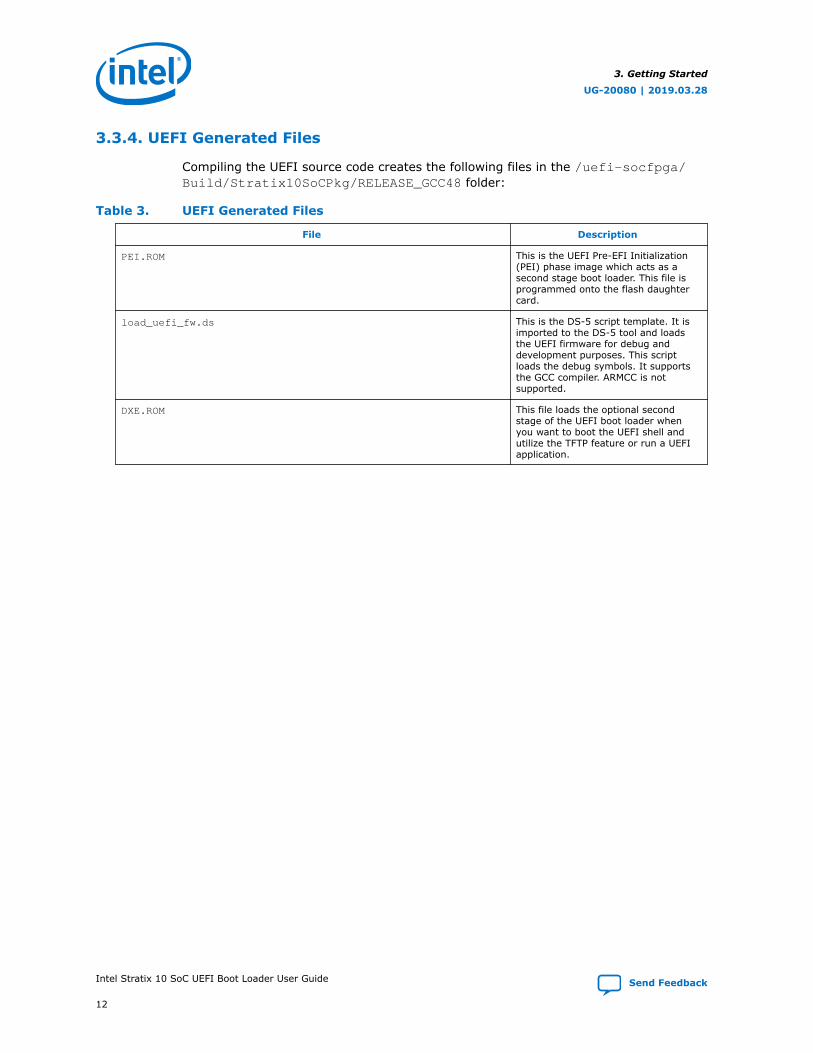
3.3.4. UEFI Generated Files
Compiling the UEFI source code creates the following files in the /uefi-socfpga/Build/Stratix10SoCPkg/RELEASE_GCC48 folder:
Table 3. UEFI Generated Files
File Description
PEI.ROM This is the UEFI Pre-EFI Initialization(PEI) phase image which acts as asecond stage boot loader. This file isprogrammed onto the flash daughtercard.
load_uefi_fw.ds This is the DS-5 script template. It isimported to the DS-5 tool and loadsthe UEFI firmware for debug anddevelopment purposes. This scriptloads the debug symbols. It supportsthe GCC compiler. ARMCC is notsupported.
DXE.ROM This file loads the optional secondstage of the UEFI boot loader whenyou want to boot the UEFI shell andutilize the TFTP feature or run a UEFIapplication.
3. Getting Started
UG-20080 | 2019.03.28
Intel Stratix 10 SoC UEFI Boot Loader User Guide Send Feedback
12
4. Running UEFI on Intel Stratix 10 Hardware
4.1. Running on a Physical Board with ATF and UEFI Bootloader
This section describes how to run the Secure Monitor on a physical board.
4.1.1. Generate a .sof file with ATF
1. Get a .sof file from the $SOCEDS_DEST_ROOT installation directory.
2. Convert the binary file bl31.bin, generated in Building the BL31 Image.
$ aarch64-linux-gnu-objcopy -I binary -O ihex - \-change-addresses 0xffe00000 bl31.bin bl31.hex
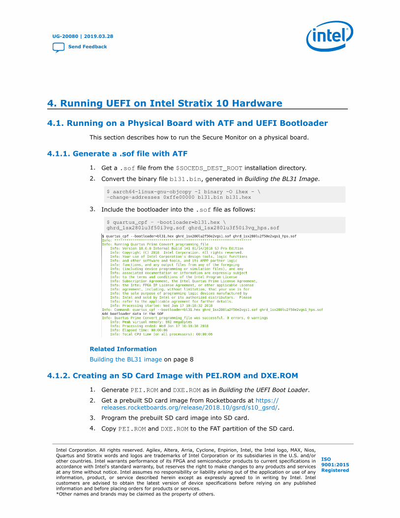
3. Include the bootloader into the .sof file as follows:
$ quartus_cpf - -bootloader=bl31.hex \ghrd_1sx280lu3f50i3vg.sof ghrd_1sx280lu3f50i3vg_hps.sof
Related Information
Building the BL31 image on page 8
4.1.2. Creating an SD Card Image with PEI.ROM and DXE.ROM
1. Generate PEI.ROM and DXE.ROM as in Building the UEFI Boot Loader.
2. Get a prebuilt SD card image from Rocketboards at https://releases.rocketboards.org/release/2018.10/gsrd/s10_gsrd/.
3. Program the prebuilt SD card image into SD card.
4. Copy PEI.ROM and DXE.ROM to the FAT partition of the SD card.
UG-20080 | 2019.03.28
Send Feedback
Intel Corporation. All rights reserved. Agilex, Altera, Arria, Cyclone, Enpirion, Intel, the Intel logo, MAX, Nios,Quartus and Stratix words and logos are trademarks of Intel Corporation or its subsidiaries in the U.S. and/orother countries. Intel warrants performance of its FPGA and semiconductor products to current specifications inaccordance with Intel's standard warranty, but reserves the right to make changes to any products and servicesat any time without notice. Intel assumes no responsibility or liability arising out of the application or use of anyinformation, product, or service described herein except as expressly agreed to in writing by Intel. Intelcustomers are advised to obtain the latest version of device specifications before relying on any publishedinformation and before placing orders for products or services.*Other names and brands may be claimed as the property of others.
ISO9001:2015Registered
Related Information
• Compiling the UEFI Source Code with the Linaro Tool Chain on page 10
• Building the UEFI Boot Loader on page 9
• https://releases.rocketboards.org/release/2018.10/gsrd/s10_gsrd/Intel Stratix 10 SoC GSRD downloads on Rocketboards
4.1.3. Running the Secure Monitor
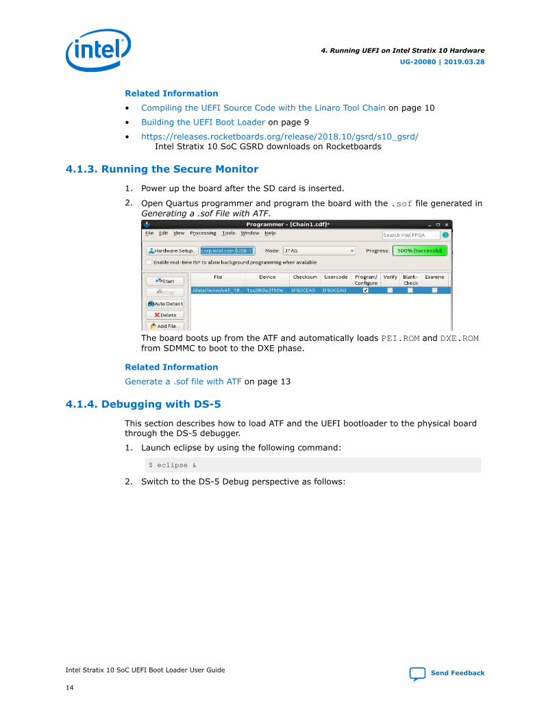
1. Power up the board after the SD card is inserted.
2. Open Quartus programmer and program the board with the .sof file generated inGenerating a .sof File with ATF.
The board boots up from the ATF and automatically loads PEI.ROM and DXE.ROMfrom SDMMC to boot to the DXE phase.
Related Information
Generate a .sof file with ATF on page 13
4.1.4. Debugging with DS-5
This section describes how to load ATF and the UEFI bootloader to the physical boardthrough the DS-5 debugger.
1. Launch eclipse by using the following command:
$ eclipse &
2. Switch to the DS-5 Debug perspective as follows:
4. Running UEFI on Intel Stratix 10 Hardware
UG-20080 | 2019.03.28
Intel Stratix 10 SoC UEFI Boot Loader User Guide Send Feedback
14
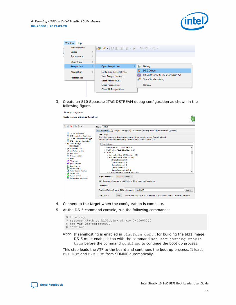
3. Create an S10 Separate JTAG DSTREAM debug configuration as shown in thefollowing figure.
4. Connect to the target when the configuration is complete.
5. At the DS-5 command console, run the following commands:
$ interrupt$ restore <Path to bl31.bin> binary 0xffe00000$ set var $pc=0xffe00000$ continue
Note: If semihosting is enabled in platform_def.h for building the bl31 image,DS-5 must enable it too with the command set semihosting enabletrue before the command continue to continue the boot up process.
This step loads the ATF to the board and continues the boot up process. It loadsPEI.ROM and DXE.ROM from SDMMC automatically.
4. Running UEFI on Intel Stratix 10 Hardware
UG-20080 | 2019.03.28
Send Feedback Intel Stratix 10 SoC UEFI Boot Loader User Guide
15
6. If you want to use the debugger to load PEI.ROM and DXE.ROM to memory,modify the configuration in your platform_def.h file and bl31_plat_setup.cfile before building the bl31 image.
7. Open the platform_def.h file located in arm-trusted-firmware/plat/intel/soc/stratix10/platform_def.h and enable semihosting as follows:
# define PLAT_SEMIHOSTING_ENABLE
8. Open arm-trusted-firmware/plat/intel/soc/stratix10/bl31_plat_setup.c and comment out the line shown below:
//LoadBootImageFile (PLAT_NS_IMAGE_NAME, PLAT_NS_IMAGE_OFFSET);
9. Regenerate the bl31 image and follow Step 5 on page 15 to load the ATF to thephysical board. Interrupt the processor through the DS-5 debugger after memoryinitialization succeeds, as follows:
$ interrupt
4. Running UEFI on Intel Stratix 10 Hardware
UG-20080 | 2019.03.28
Intel Stratix 10 SoC UEFI Boot Loader User Guide Send Feedback
16
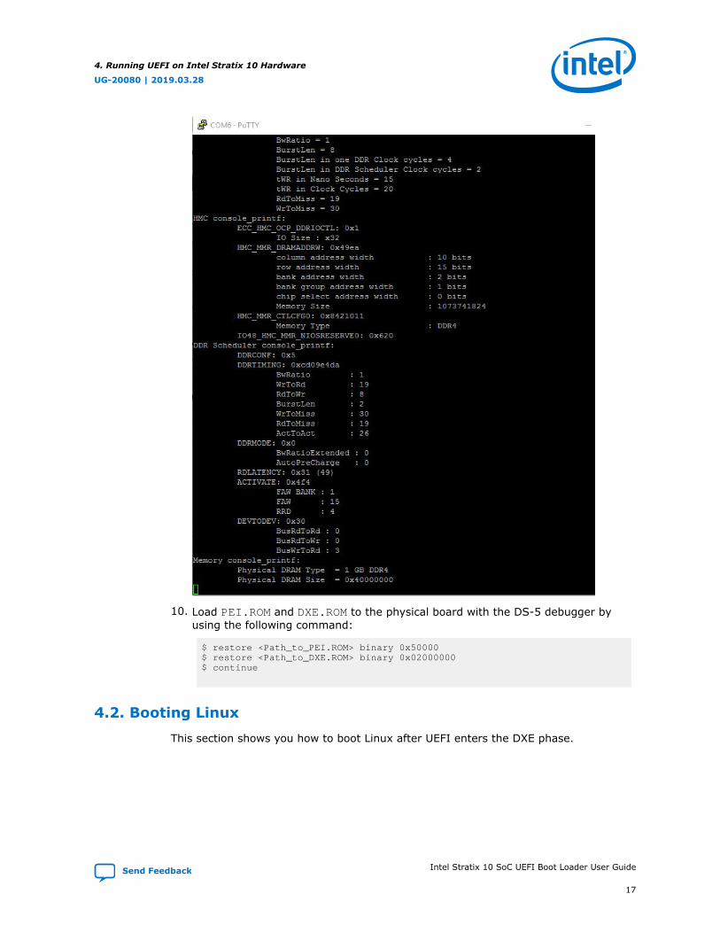
10. Load PEI.ROM and DXE.ROM to the physical board with the DS-5 debugger byusing the following command:
$ restore <Path_to_PEI.ROM> binary 0x50000$ restore <Path_to_DXE.ROM> binary 0x02000000$ continue
4.2. Booting Linux
This section shows you how to boot Linux after UEFI enters the DXE phase.
4. Running UEFI on Intel Stratix 10 Hardware
UG-20080 | 2019.03.28
Send Feedback Intel Stratix 10 SoC UEFI Boot Loader User Guide
17

4.2.1. Booting from the DXE Console
1. Boot the board up to the DXE phase, as described in Running the Secure Monitor.
2. Once the DXE phase is loaded, enter the following command to boot Linux:
$ Linuxloader fs1:Image -d fs1:socfpga_stratix10_socdk.dtb \-c "console=ttyS0,115200 root=/dev/mmcblk0p2 rwrootwait"
Note: Make sure Linux image is stored in the SD card.
Related Information
Running the Secure Monitor on page 14
4. Running UEFI on Intel Stratix 10 Hardware
UG-20080 | 2019.03.28
Intel Stratix 10 SoC UEFI Boot Loader User Guide Send Feedback
18
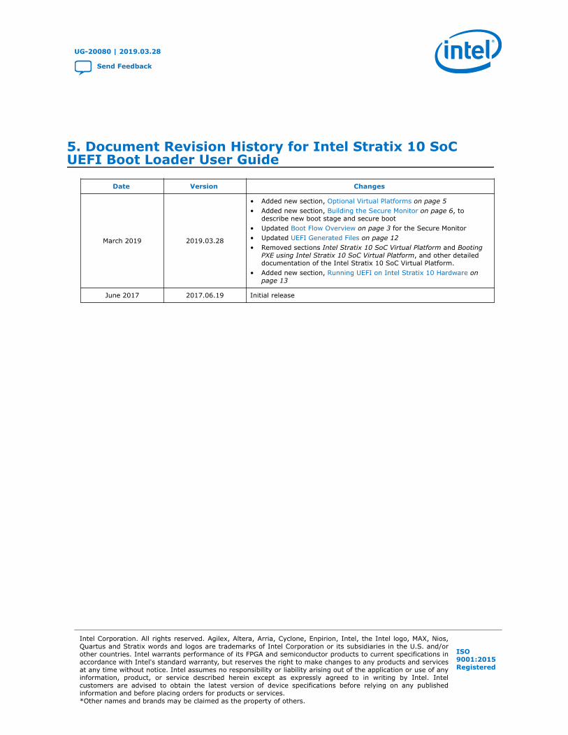
5. Document Revision History for Intel Stratix 10 SoCUEFI Boot Loader User Guide
Date Version Changes
March 2019 2019.03.28
• Added new section, Optional Virtual Platforms on page 5• Added new section, Building the Secure Monitor on page 6, to
describe new boot stage and secure boot• Updated Boot Flow Overview on page 3 for the Secure Monitor• Updated UEFI Generated Files on page 12• Removed sections Intel Stratix 10 SoC Virtual Platform and Booting
PXE using Intel Stratix 10 SoC Virtual Platform, and other detaileddocumentation of the Intel Stratix 10 SoC Virtual Platform.
• Added new section, Running UEFI on Intel Stratix 10 Hardware onpage 13
June 2017 2017.06.19 Initial release
UG-20080 | 2019.03.28
Send Feedback
Intel Corporation. All rights reserved. Agilex, Altera, Arria, Cyclone, Enpirion, Intel, the Intel logo, MAX, Nios,Quartus and Stratix words and logos are trademarks of Intel Corporation or its subsidiaries in the U.S. and/orother countries. Intel warrants performance of its FPGA and semiconductor products to current specifications inaccordance with Intel's standard warranty, but reserves the right to make changes to any products and servicesat any time without notice. Intel assumes no responsibility or liability arising out of the application or use of anyinformation, product, or service described herein except as expressly agreed to in writing by Intel. Intelcustomers are advised to obtain the latest version of device specifications before relying on any publishedinformation and before placing orders for products or services.*Other names and brands may be claimed as the property of others.
ISO9001:2015Registered