Intel Storage System SSR316MJ2 Backplane Board ... Storage System SSR316MJ2 Backplane Board...
27
Intel ® Storage System SSR316MJ2 Backplane Board (FMJBACKPLANE2) Installation Guide Order Number: D27076-001
Transcript of Intel Storage System SSR316MJ2 Backplane Board ... Storage System SSR316MJ2 Backplane Board...

Intel® Storage System SSR316MJ2 Backplane Board (FMJBACKPLANE2) Installation Guide
Order Number: D27076-001

Disclaimer
Information in this document is provided in connection with Intel® products. No license, express or implied, by estoppel or otherwise, to any intellectual property rights is granted by this document. Except as provided in Intel's Terms and Conditions of Sale for such products, Intel assumes no liability whatsoever, and Intel disclaims any express or implied warranty, relating to sale and/or use of Intel products including liability or warranties relating to fitness for a particular purpose, merchantability, or infringement of any patent, copyright or other intellectual property right. Intel products are not designed, intended or authorized for use in any medical, life saving, or life sustaining applications or for any other application in which the failure of the Intel product could create a situation where personal injury or death may occur. Intel may make changes to specifications and product descriptions at any time, without notice.
Intel is a registered trademark of Intel Corporation or its subsidiaries in the United States and other countries.
* Other names and brands may be claimed as the property of others.
Copyright © 2004 - 2005 Intel Corporation. All Rights Reserved.

Intel® Storage System SSR316MJ2 Backplane Board iii
Important Safety Instructions Important Safety Instructions
Read all caution and safety statements in this document before performing any of the instructions. See Intel Server Boards and Server Chassis Safety Information at http://support.intel.com/support/motherboards/server/sb/CS-010770.htm.
Wichtige Sicherheitshinweise
Lesen Sie zunächst sämtliche Warn- und Sicherheitshinweise in diesem Dokument, bevor Sie eine der Anweisungen ausführen. Beachten Sie hierzu auch die Sicherheitshinweise zu Intel-Serverplatinen und -Servergehäusen unter http://support.intel.com/support/motherboards/server/sb/CS-010770.htm.
重要安全指导
在执行任何指令之前,请阅读本文档中的所有注意事项及安全声明。
和/或http://support.intel.com/support/motherboards/server/sb/CS-010770.htm 上的 Intel Server Boards and Server Chassis Safety Information(《Intel
服务器主板与服务器机箱安全信息》)。
Consignes de sécurité
Lisez attention toutes les consignes de sécurité et les mises en garde indiquées dans ce document avant de suivre toute instruction. Consultez Intel Server Boards and Server Chassis Safety Information rendez-vous sur le site http://support.intel.com/support/motherboards/server/sb/CS-010770.htm.
Instrucciones de seguridad importantes
Lea todas las declaraciones de seguridad y precaución de este documento antes de realizar cualquiera de las instrucciones. Vea Intel Server Boards and Server Chassis Safety Information en http://support.intel.com/support/motherboards/server/sb/CS-010770.htm.

iv Intel® Storage System SSR316MJ2 Backplane Board
WARNINGS Storage system power on/off: The push-button on/off power switch on the front panel of the storage system does not turn off the AC power. To remove AC power from the storage system, you must unplug the AC power cord from either the power supply or wall outlet.
Hazardous conditions—power supply: Hazardous voltage, current, and energy levels are present inside the power supply enclosure. There are no user-serviceable parts inside the power supply; servicing should only be done by technically qualified personnel.
Hazardous conditions—devices and cables: Hazardous electrical conditions may be present on power, telephone, and communication cables. Turn off the storage system and disconnect telecommunications systems, networks, modems, and the power cord attached to the storage system before opening it. Failure to do so can result in personal injury or equipment damage.
Avoid injury: Lifting the storage system chassis and attaching it to the rack is a two-person job. If needed, use an appropriate lifting device. A fully loaded Intel® Storage System SSR316MJ2 weighs approximately 31.8 kg (70 lbs.).
CAUTIONS Temperature: The operating temperature of the storage system, when installed in an equipment rack, must not go below 5° C (41° F) or rise above 35° C (95° F). Extreme fluctuations in temperature can cause a variety of problems in the storage system.
Ventilation: The equipment rack must provide sufficient airflow to the front of the storage system to maintain proper cooling. It must also include ventilation sufficient to exhaust a maximum of 1900 BTUs per hour for a fully loaded Intel® Storage System SSR316MJ2.
v Intel® Storage System SSR316MJ2 Backplane Board
Contents
About the Backplane Board Assembly ............................................................. 7 Contents.................................................................................................................................. 7
Backplane Board Installation Procedures ........................................................ 8 Required Tools........................................................................................................................ 8 Power Down System and Remove Chassis Cover ................................................................. 8 Unseat Hard Disk Drive Carriers............................................................................................. 9 Disconnect Front Panel Cables............................................................................................. 10 Remove Fan Assembly Screws ............................................................................................ 11 Disconnect Fan Cables ......................................................................................................... 12 Remove Fan Assembly and Disconnect SATA Cables......................................................... 13 Cut SATA Cable Ties ............................................................................................................14 Disconnect I2C Cables........................................................................................................... 15 Disconnect Power Distribution Module Cables ..................................................................... 16 Remove Backplane Board .................................................................................................... 17 Install New Backplane Board ................................................................................................ 18 Connect Power Distribution Module Cables.......................................................................... 19 Connect SATA Cables .......................................................................................................... 20 Connect I2C Cables ............................................................................................................... 21 Install Fan Assembly ............................................................................................................. 22 Attach Fan Assembly ............................................................................................................23 Connect System Fan Cables ................................................................................................ 24 Connect Front Panel Board Cables ...................................................................................... 25 Seat Hard Disk Drive Carriers............................................................................................... 26 Finishing Up .......................................................................................................................... 27
vi Intel® Storage System SSR316MJ2 Backplane Board
Figures Figure 1. Removing Chassis Cover ........................................................................................ 8 Figure 2. Unseating Hard Disk Carriers .................................................................................. 9 Figure 3. Disconnecting Front Panel Cables......................................................................... 10 Figure 4. Removing System Fan Assembly Screws ............................................................. 11 Figure 5. Disconnecting System Fan Cables ........................................................................ 12 Figure 6. Removing System Fan Assembly and Disconnecting SATA Cables..................... 13 Figure 7. Cutting SATA Cable Ties ....................................................................................... 14 Figure 8. Disconnecting I2C Cables....................................................................................... 15 Figure 9. Disconnecting Power Distribution Module Cables ................................................. 16 Figure 10. Removing Backplane Board ................................................................................ 17 Figure 11. Installing New Backplane Board .......................................................................... 18 Figure 12. Connecting Power Distribution Module Cables.................................................... 19 Figure 13. Connecting SATA Cables .................................................................................... 20 Figure 14. Connecting I2C Cables ......................................................................................... 21 Figure 15. Installing System Fan Assembly .......................................................................... 22 Figure 16. Attaching System Fan Assembly ......................................................................... 23 Figure 17. Connecting System Fan Cables .......................................................................... 24 Figure 18. Connecting Front Panel Board Cables ................................................................ 25 Figure 19. Seating Hard Disk Drives..................................................................................... 26 Figure 20. Installing the Chassis Cover ................................................................................ 27
Intel® Storage System SSR316MJ2 Backplane Board 7
About the Backplane Board Assembly
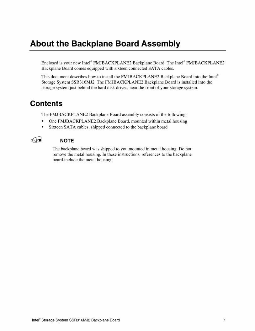
Enclosed is your new Intel® FMJBACKPLANE2 Backplane Board. The Intel® FMJBACKPLANE2 Backplane Board comes equipped with sixteen connected SATA cables.
This document describes how to install the FMJBACKPLANE2 Backplane Board into the Intel® Storage System SSR316MJ2. The FMJBACKPLANE2 Backplane Board is installed into the storage system just behind the hard disk drives, near the front of your storage system.
Contents The FMJBACKPLANE2 Backplane Board assembly consists of the following:
One FMJBACKPLANE2 Backplane Board, mounted within metal housing Sixteen SATA cables, shipped connected to the backplane board
NOTE
The backplane board was shipped to you mounted in metal housing. Do not remove the metal housing. In these instructions, references to the backplane board include the metal housing.
8
Backplane Board Installation Procedures
Required Tools Cross-head (Number 1 size Phillips*) screwdriver, with a maximum length of 4 inches Wire-cutter
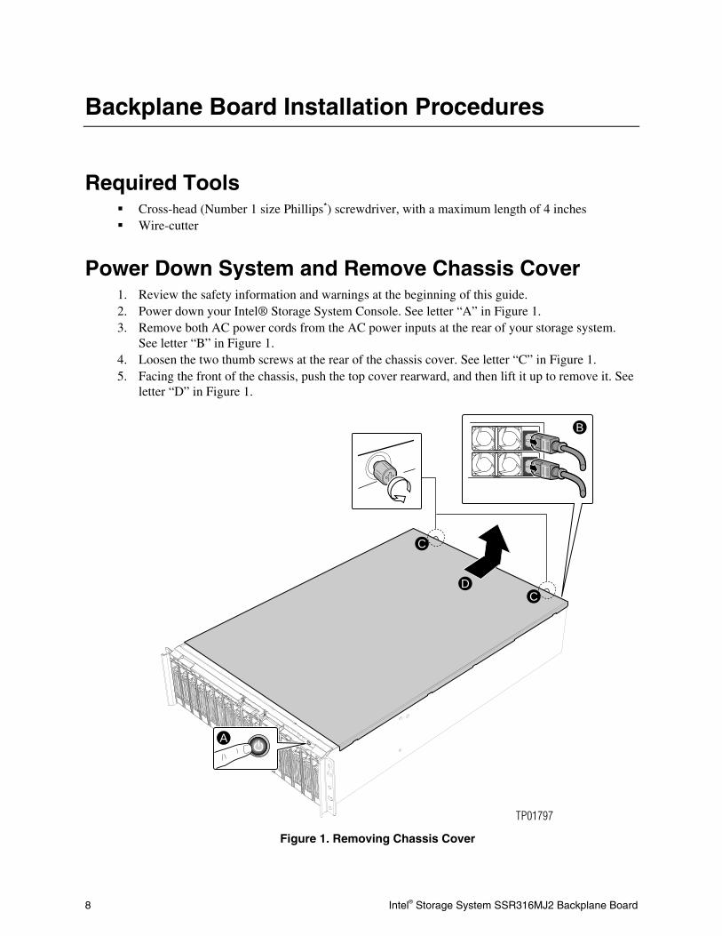
Power Down System and Remove Chassis Cover 1. Review the safety information and warnings at the beginning of this guide. 2. Power down your Intel® Storage System Console. See letter “A” in Figure 1. 3. Remove both AC power cords from the AC power inputs at the rear of your storage system.
See letter “B” in Figure 1. 4. Loosen the two thumb screws at the rear of the chassis cover. See letter “C” in Figure 1. 5. Facing the front of the chassis, push the top cover rearward, and then lift it up to remove it. See
letter “D” in Figure 1.
A
D
B
C
C
Figure 1. R
Intel® Storage System SSR316MJ2 Backplane Board
TP01797
emoving Chassis Cover
Intel® Storage System SSR316MJ2 Backplane Board 9
Unseat Hard Disk Drive Carriers
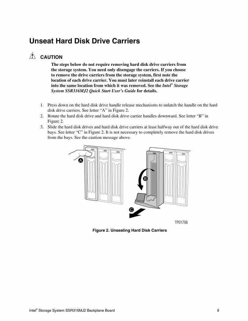
CAUTION The steps below do not require removing hard disk drive carriers from the storage system. You need only disengage the carriers. If you choose to remove the drive carriers from the storage system, first note the location of each drive carrier. You must later reinstall each drive carrier into the same location from which it was removed. See the Intel® Storage System SSR316MJ2 Quick Start User’s Guide for details.
1. Press down on the hard disk drive handle release mechanisms to unlatch the handle on the hard disk drive carriers. See letter “A” in Figure 2.
2. Rotate the hard disk drive and hard disk drive carrier handles downward. See letter “B” in Figure 2.
3. Slide the hard disk drives and hard disk drive carriers at least halfway out of the hard disk drive bays. See letter “C” in Figure 2. It is not necessary to completely remove the hard disk drives from the bays. See the caution message above.
A
B
C
TP01798
Figure 2. Unseating Hard Disk Carriers
10 Intel® Storage System SSR316MJ2 Backplane Board
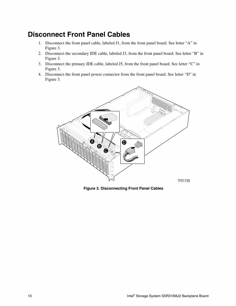
Disconnect Front Panel Cables 1. Disconnect the front panel cable, labeled J1, from the front panel board. See letter “A” in
Figure 3. 2. Disconnect the secondary IDE cable, labeled J3, from the front panel board. See letter “B” in
Figure 3. 3. Disconnect the primary IDE cable, labeled J5, from the front panel board. See letter “C” in
Figure 3. 4. Disconnect the front panel power connector from the front panel board. See letter “D” in
Figure 3.
AB
C
D
TP01799
Figure 3. Disconnecting Front Panel Cables

Intel® Storage System SSR316MJ2 Backplane Board 11
Remove Fan Assembly Screws Use a Number 1 size Phillips* screwdriver to remove the screw on each side of the system. See letter “A” in Figure 4. These screws hold the system fan assembly in place. See Figure 4. These screws will be re-installed later.
A
TP01800
Figure 4. Removing System Fan Assembly Screws

12 Intel® Storage System SSR316MJ2 Backplane Board
Disconnect Fan Cables 1. Disconnect the Fan 3 cable from the server board. See letter “A” in Figure 5. 2. Disconnect the Fan 4 cable from the server board. See letter “B” in Figure 5. 3. Disconnect the Fan 5 cable from the server board. See letter “C” in Figure 5.
A
A
B
C
B
C
TP01801
Figure 5. Disconnecting System Fan Cables
Intel® Storage System SSR316MJ2 Backplane Board 13
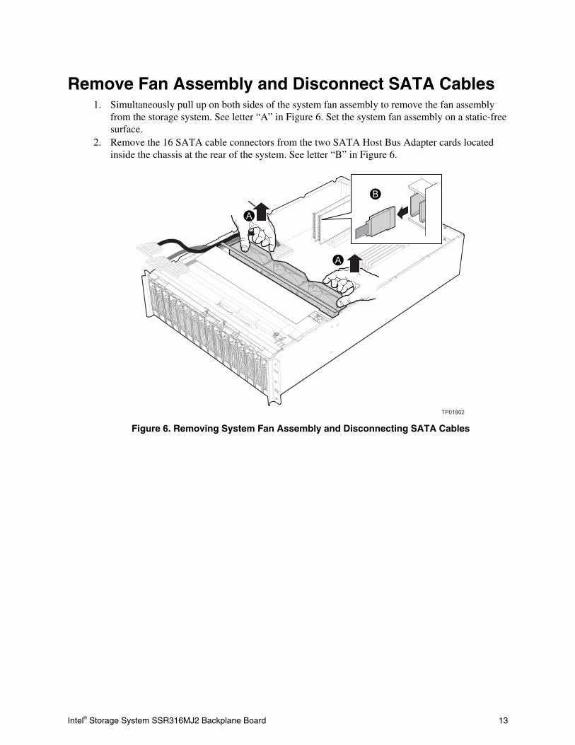
Remove Fan Assembly and Disconnect SATA Cables 1. Simultaneously pull up on both sides of the system fan assembly to remove the fan assembly
from the storage system. See letter “A” in Figure 6. Set the system fan assembly on a static-free surface.
2. Remove the 16 SATA cable connectors from the two SATA Host Bus Adapter cards located inside the chassis at the rear of the system. See letter “B” in Figure 6.
A
A
TP01802
B
Figure 6. Removing System Fan Assembly and Disconnecting SATA Cables
14 Intel® Storage System SSR316MJ2 Backplane Board
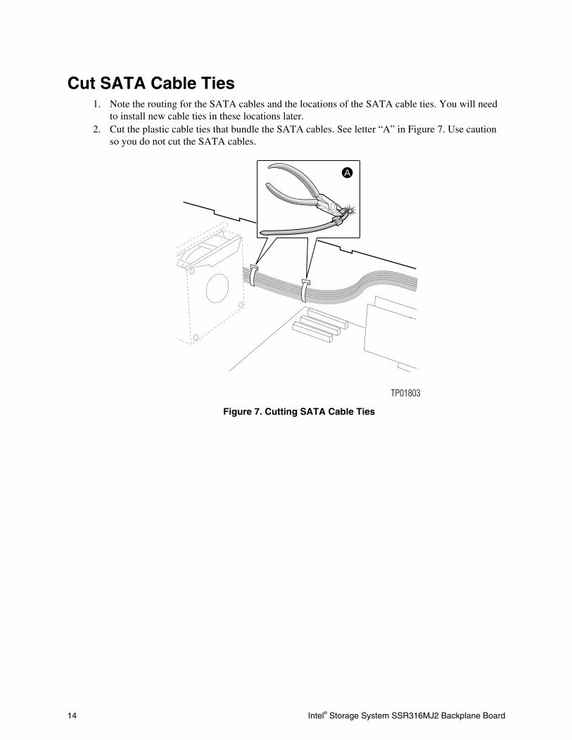
Cut SATA Cable Ties 1. Note the routing for the SATA cables and the locations of the SATA cable ties. You will need
to install new cable ties in these locations later. 2. Cut the plastic cable ties that bundle the SATA cables. See letter “A” in Figure 7. Use caution
so you do not cut the SATA cables.
A
TP01803
Figure 7. Cutting SATA Cable Ties

Intel® Storage System SSR316MJ2 Backplane Board 15
Disconnect I2C Cables
NOTE
The I2C cables are labeled at each end, on the cable connector. In the instructions and the figure below, it is assumed that letter “A” corresponds to your cable labeled JP4 and SL3_J13. Your connections may be different. It is important that you write down the connections as they exist in your chassis, so you may later correctly reconnect them.
In these steps, you do not need to disconnect the I2C cables from the Host Bus Adapter cards. If you choose to disconnect the cables from the cards, make sure you also write down these cable connections.
1. Write down the I2C cable connector positions on the backplane board. You will later need to re-
connect these cables to the same headers. 2. Disconnect the I2C cable that is labeled JP4 from the backplane board at the front of the chassis.
See letter “A” in the circled area of Figure 8. 3. Disconnect the I2C cable that is labeled JP6 from the backplane board. See letter “B” in the
circled area of Figure 8.
TP01804
B
A
B
A
Figure 8. Disconnecting I2C Cables
16 Intel® Storage System SSR316MJ2 Backplane Board
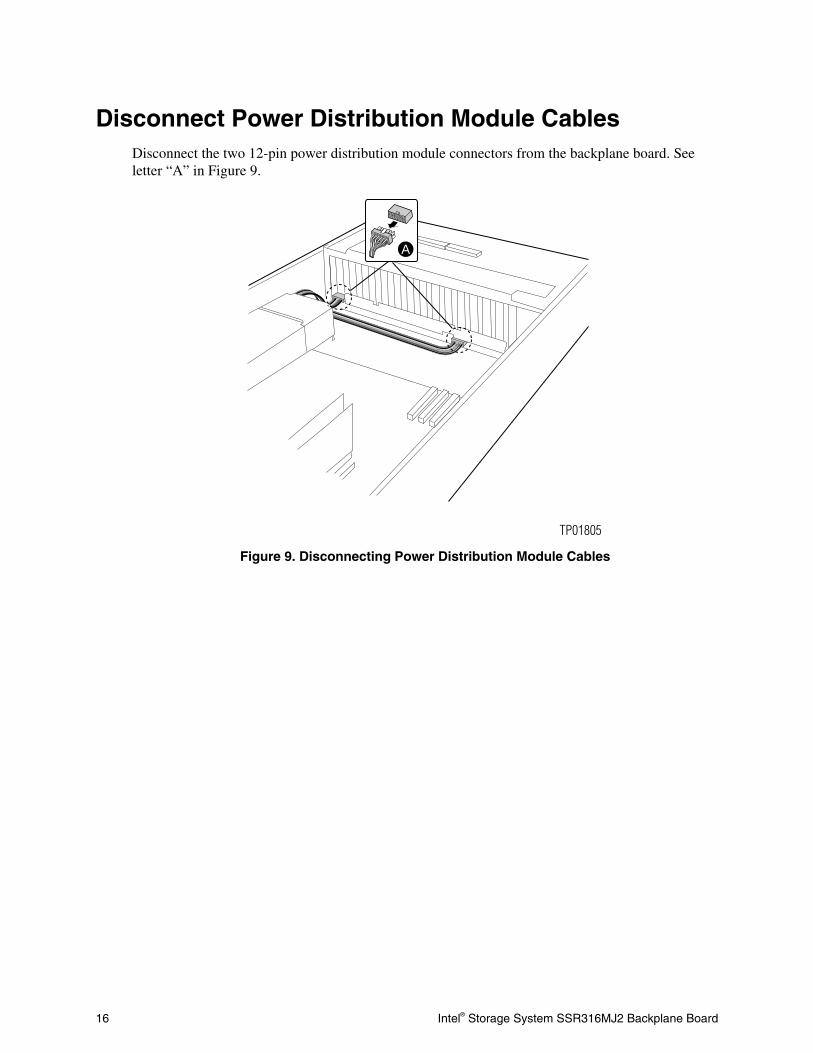
Disconnect Power Distribution Module Cables Disconnect the two 12-pin power distribution module connectors from the backplane board. See letter “A” in Figure 9.
A
TP01805
Figure 9. Disconnecting Power Distribution Module Cables
Intel® Storage System SSR316MJ2 Backplane Board 17
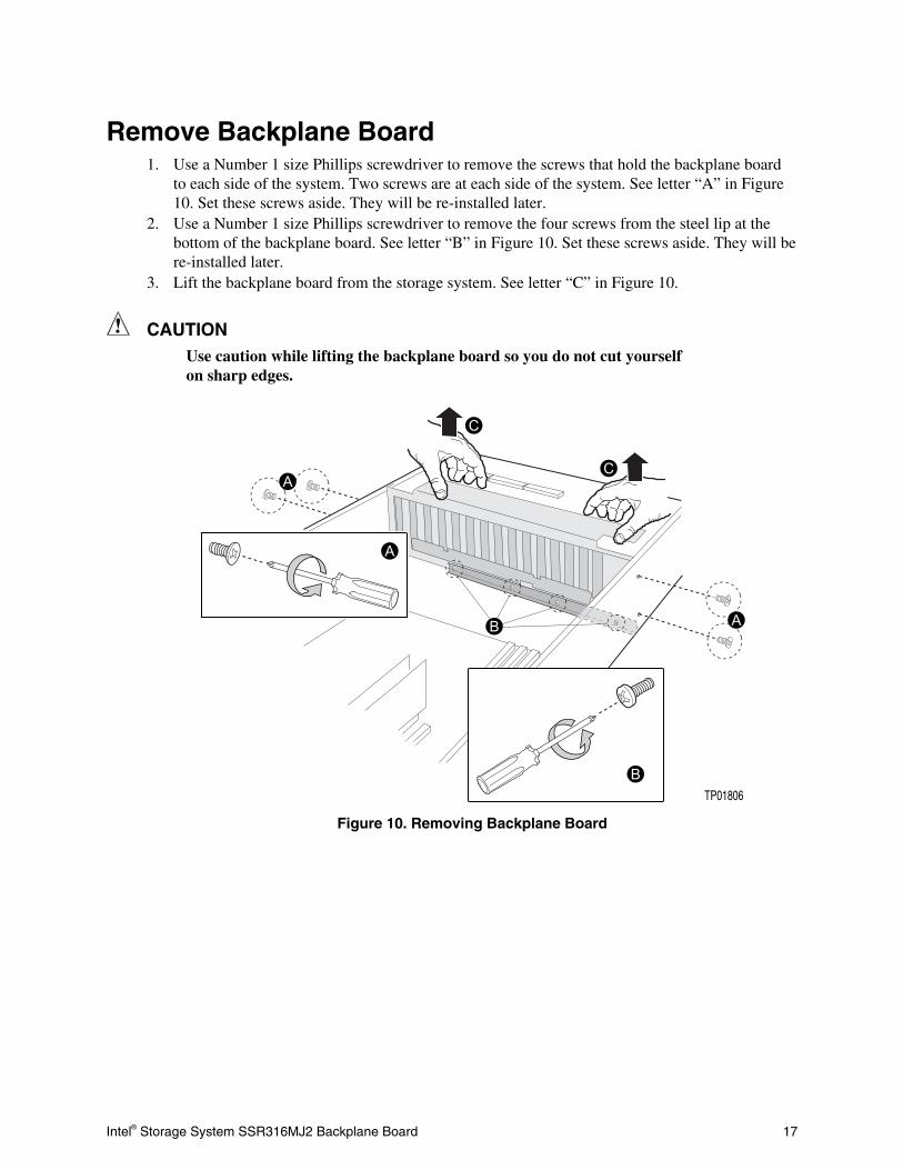
Remove Backplane Board 1. Use a Number 1 size Phillips screwdriver to remove the screws that hold the backplane board
to each side of the system. Two screws are at each side of the system. See letter “A” in Figure 10. Set these screws aside. They will be re-installed later.
2. Use a Number 1 size Phillips screwdriver to remove the four screws from the steel lip at the bottom of the backplane board. See letter “B” in Figure 10. Set these screws aside. They will be re-installed later.
3. Lift the backplane board from the storage system. See letter “C” in Figure 10.
CAUTION Use caution while lifting the backplane board so you do not cut yourself on sharp edges.
TP01806
Figure 10. Removing Backplane Board
18 Intel® Storage System SSR316MJ2 Backplane Board
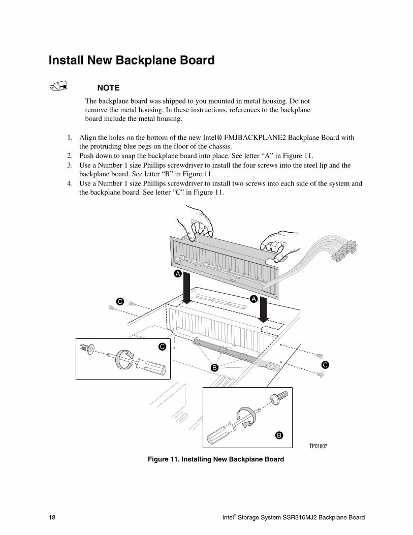
Install New Backplane Board
NOTE
The backplane board was shipped to you mounted in metal housing. Do not remove the metal housing. In these instructions, references to the backplane board include the metal housing.
1. Align the holes on the bottom of the new Intel® FMJBACKPLANE2 Backplane Board with the protruding blue pegs on the floor of the chassis.
2. Push down to snap the backplane board into place. See letter “A” in Figure 11. 3. Use a Number 1 size Phillips screwdriver to install the four screws into the steel lip and the
backplane board. See letter “B” in Figure 11. 4. Use a Number 1 size Phillips screwdriver to install two screws into each side of the system and
the backplane board. See letter “C” in Figure 11.
TP01807
Figure 11. Installing New Backplane Board

Intel® Storage System SSR316MJ2 Backplane Board 19
Connect Power Distribution Module Cables Connect the two 12-pin Power Distribution Module cables to the backplane board. See letter “A” in Figure 12.
A
TP01808
Figure 12. Connecting Power Distribution Module Cables
20 Intel® Storage System SSR316MJ2 Backplane Board
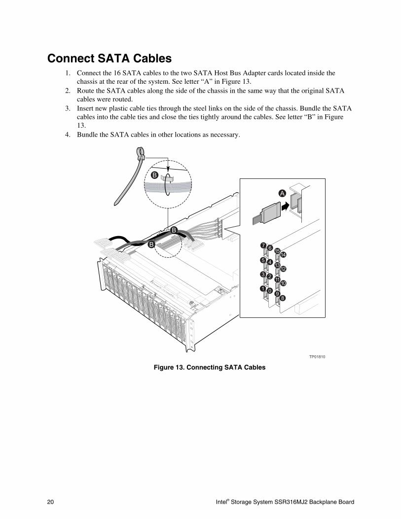
Connect SATA Cables 1. Connect the 16 SATA cables to the two SATA Host Bus Adapter cards located inside the
chassis at the rear of the system. See letter “A” in Figure 13. 2. Route the SATA cables along the side of the chassis in the same way that the original SATA
cables were routed. 3. Insert new plastic cable ties through the steel links on the side of the chassis. Bundle the SATA
cables into the cable ties and close the ties tightly around the cables. See letter “B” in Figure 13.
4. Bundle the SATA cables in other locations as necessary.
Figure 13. Connecting SATA Cables
Intel® Storage System SSR316MJ2 Backplane Board 21
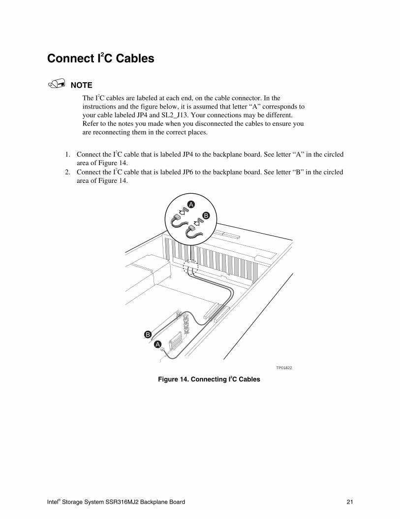
Connect I2C Cables
NOTE
The I2C cables are labeled at each end, on the cable connector. In the instructions and the figure below, it is assumed that letter “A” corresponds to your cable labeled JP4 and SL2_J13. Your connections may be different. Refer to the notes you made when you disconnected the cables to ensure you are reconnecting them in the correct places.
1. Connect the I2C cable that is labeled JP4 to the backplane board. See letter “A” in the circled
area of Figure 14. 2. Connect the I2C cable that is labeled JP6 to the backplane board. See letter “B” in the circled
area of Figure 14.
TP01822
BA
B
A
Figure 14. Connecting I2C Cables
22 Intel® Storage System SSR316MJ2 Backplane Board
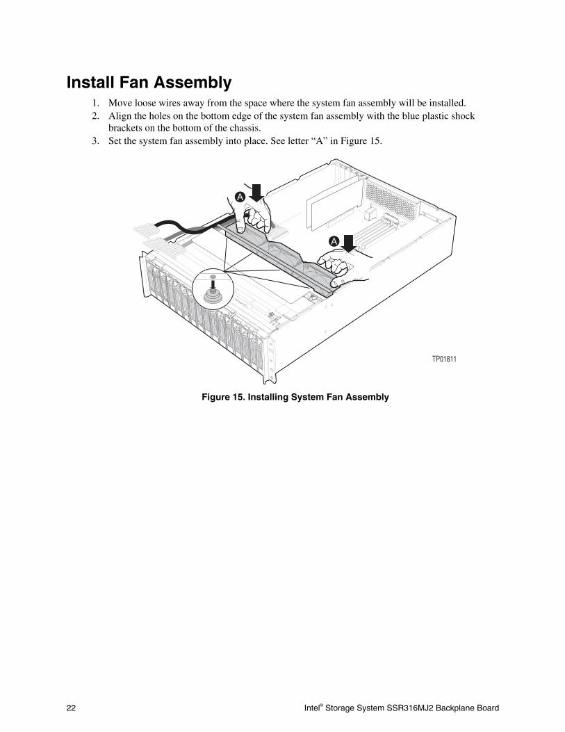
Install Fan Assembly 1. Move loose wires away from the space where the system fan assembly will be installed. 2. Align the holes on the bottom edge of the system fan assembly with the blue plastic shock
brackets on the bottom of the chassis. 3. Set the system fan assembly into place. See letter “A” in Figure 15.
A
A
TP01811
Figure 15. Installing System Fan Assembly
Intel® Storage System SSR316MJ2 Backplane Board 23
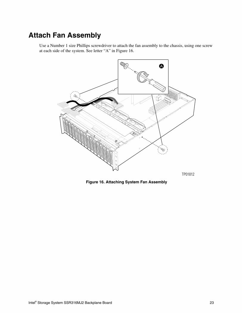
Attach Fan Assembly Use a Number 1 size Phillips screwdriver to attach the fan assembly to the chassis, using one screw at each side of the system. See letter “A” in Figure 16.
A
TP01812
Figure 16. Attaching System Fan Assembly
24 Intel® Storage System SSR316MJ2 Backplane Board
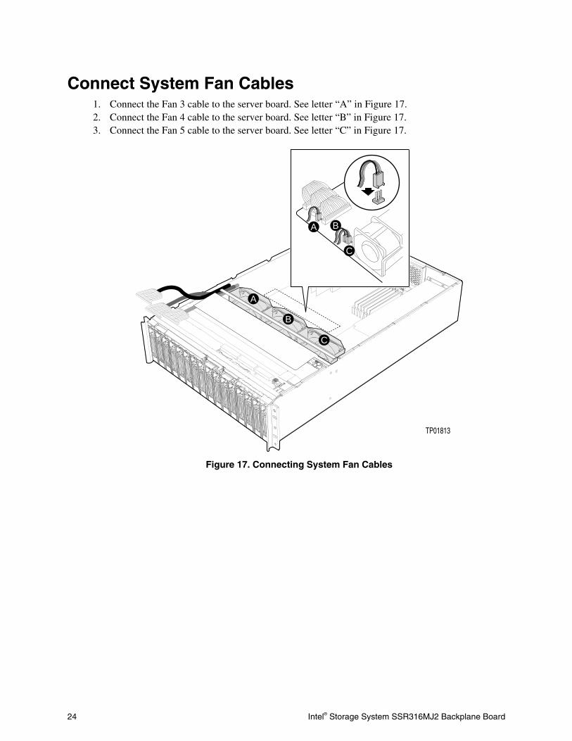
Connect System Fan Cables 1. Connect the Fan 3 cable to the server board. See letter “A” in Figure 17. 2. Connect the Fan 4 cable to the server board. See letter “B” in Figure 17. 3. Connect the Fan 5 cable to the server board. See letter “C” in Figure 17.
A
A
B
C
B
C
TP01813
Figure 17. Connecting System Fan Cables
Intel® Storage System SSR316MJ2 Backplane Board 25
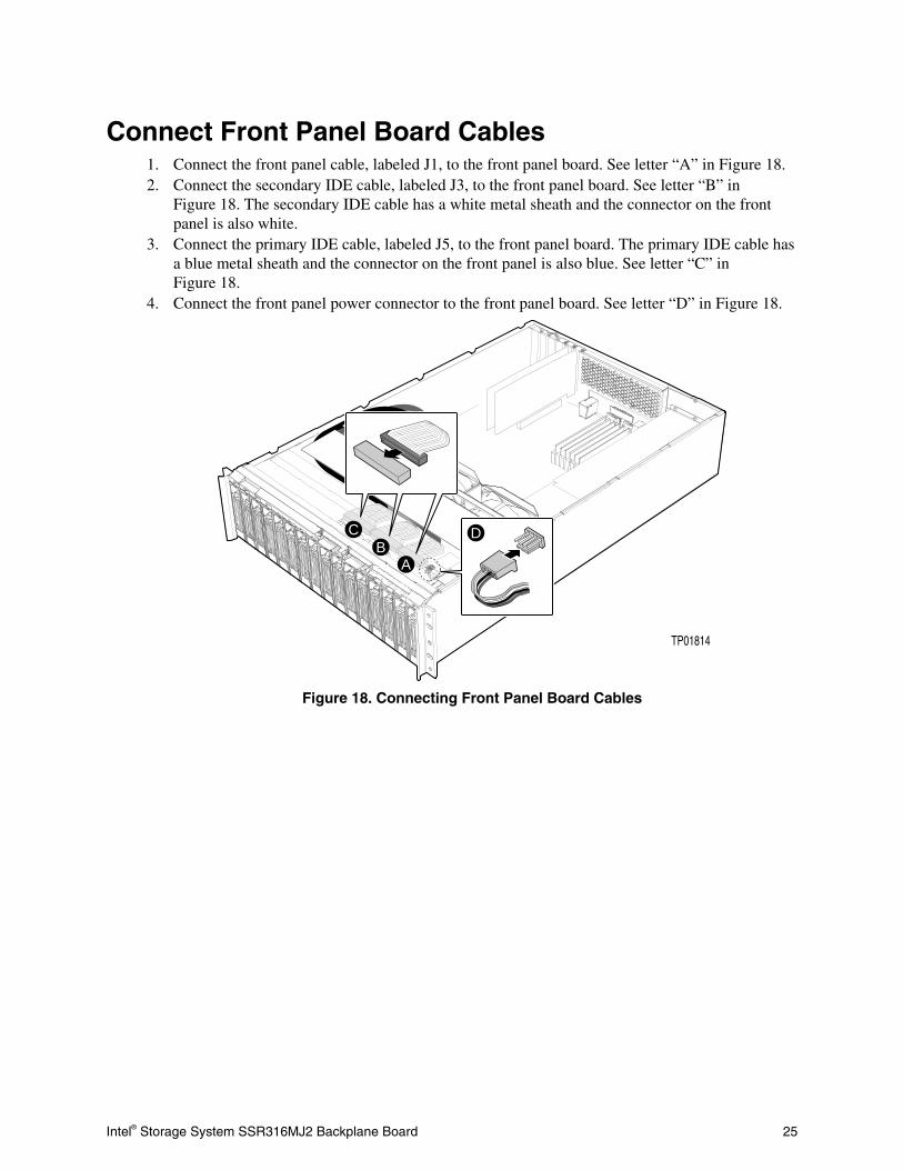
Connect Front Panel Board Cables 1. Connect the front panel cable, labeled J1, to the front panel board. See letter “A” in Figure 18. 2. Connect the secondary IDE cable, labeled J3, to the front panel board. See letter “B” in
Figure 18. The secondary IDE cable has a white metal sheath and the connector on the front panel is also white.
3. Connect the primary IDE cable, labeled J5, to the front panel board. The primary IDE cable has a blue metal sheath and the connector on the front panel is also blue. See letter “C” in Figure 18.
4. Connect the front panel power connector to the front panel board. See letter “D” in Figure 18.
CB
A
D
TP01814
Figure 18. Connecting Front Panel Board Cables

26 Intel® Storage System SSR316MJ2 Backplane Board
Seat Hard Disk Drive Carriers 1. Slide all sixteen hard disk drive carriers into the bays until they stop. See letter “A” in
Figure 19. 2. Push the handles up until they latch into place. See letter “B” in Figure 19.
BA
TP01815
Figure 19. Seating Hard Disk Drives

Intel® Storage System SSR316MJ2 Backplane Board 27
Finishing Up 1. Facing the front of the system, set the chassis cover into the corresponding slot in the chassis. 2. Pull the top cover forward. See letter “A” in Figure 20. 3. Tighten the two thumb screws at the rear of the chassis. See letter “B” in Figure 20. 4. Connect the AC power cables. See letter “C” in Figure 20. 5. Power on your Intel® Storage System Console. See letter “D” in Figure 20.
D
A
C
B
B
TP01816
Figure 20. Installing the Chassis Cover