Intel Architecture Overview By Ren-Hung Hwang
36
Intel Architecture Overview By Ren-Hung Hwang 6\VWHP DUFKLWHFWXUHRYHUYLHZ 1.1: Intel system architecture (from Intel Architecture Software Developer’s Manual)
Transcript of Intel Architecture Overview By Ren-Hung Hwang

Intel Architecture Overview
By
Ren-Hung Hwang
���6\VWHP�DUFKLWHFWXUH�RYHUYLHZ �
� 1.1: Intel system architecture
(from Intel Architecture Software Developer’s Manual)

☞GLOBAL AND LOCAL DESCRIPTOR TABLES When operating in protected mode, all memory accesses pass through either the
global descriptor table (GDT) or the (optional) local descriptor table (LDT). These
tables contain entries called segment descriptors. A segment descriptor provides the
base address of a segment and access rights, type, and usage information. Each segment
descriptor has a segment selector associated with it. The segment selector provides an
index into the GDT or LDT (to its associated segment descriptor), a global/local flag
(that determines whether the segment selector points to the GDT or the LDT), and
access rights information.
To access a byte in a segment, both a segment selector and an offset must be
supplied. The segment selector provides access to the segment descriptor for the
segment (in the GDT or LDT). From the segment descriptor, the processor obtains the
base address of the segment in the linear address space. The offset then provides the
location of the byte relative to the base address. This mechanism can be used to access
any valid code, data, or stack segment in the GDT or LDT, provided the segment is
accessible from the current privilege level (CPL) at which the processor is operating.
(The CPL is defined as the protection level of the currently executing code segment.)
In Figure 1-1 the solid arrows indicate a linear address, the dashed lines indicate a
segment selector, and the dotted arrows indicate a physical address. For simplicity,
many of the segment selectors are shown as direct pointers to a segment. However, the
actual path from a segment selector to its associated segment is always through the
GDT or LDT.
The linear address of the base of the GDT is contained in the GDT register
(GDTR); the linear address of the LDT is contained in the LDT register (LDTR).
☞SYSTEM SEGMENTS, SEGMENT DESCRIPTORS, AND GATES Besides the code, data, and stack segments that make up the execution
environment of a program or procedure, the system architecture also defines two system
segments: the task-state segment (TSS) and the LDT. (The GDT is not considered a
segment because it is not accessed by means of a segment selector and segment
descriptor.) Each of these segment types has a segment descriptor defined for it.
The system architecture also defines a set of special descriptors called gates (the
call gate, interrupt gate, trap gate, and task gate) that provide protected gateways to
system procedures and handlers that operate at different privilege levels than application
programs and procedures. For example, a CALL to a call gate provides access to a
procedure in a code segment that is at the same or numerically lower privilege level
(more privileged) than the current code segment. To access a procedure through a call
gate, the calling procedure must supply the selector of the call gate. The processor than
performs an access rights check on the call gate, comparing the CPL with the privilege
level of the call gate and the destination code segment pointed to by the call gate. If

access to the destination code segment is allowed, the processor gets the segment
selector for the destination code segment and an offset into that code segment from the
call gate. If the call requires a change in privilege level, the processor also switches to
the stack for that privilege level. (The segment selector for the new stack is obtained
from the TSS for the currently running task.) Gates also facilitate transitions between
16-bit and 32-bit code segments, and vice versa.
☞TASK-STATE SEGMENTS AND TASK GATES The TSS defines the state of the execution environment for a task. It includes the
state of the general-purpose registers, the segment registers, the EFLAGS register, the
EIP register, and segment selectors and stack pointers for three stack segments (one
stack each for privilege levels 0, 1, and 2). It also includes the segment selector for the
LDT associated with the task and the page-table base address.
All program execution in protected mode happens within the context of a task,
called the current task. The segment selector for the TSS for the current task is stored in
the task register. The simplest method of switching to a task is to make a call or jump to
the task. Here, the segment selector for the TSS of the new task is given in the CALL or
JMP instruction. A task can also be accessed through a task gate. A task gate is similar
to a call gate, except that it provides access (through a segment selector) to a TSS rather
than a code segment.
☞INTERRUPT AND EXCEPTION HANDLING External interrupts, software interrupts, and exceptions are handled through the
interrupt descriptor table (IDT), see Figure 1-1. The IDT contains a collection of gate
descriptors, which provide access to interrupt and exception handlers. Like the GDT, the
IDT is not a segment. The linear address of the base of the IDT is contained in the IDT
register (IDTR).
The gate descriptors in the IDT can be of the interrupt-, trap-, or task-gate type. To
access an interrupt or exception handler, the processor must first receive an interrupt
vector (interrupt number) from internal hardware, an external interrupt controller, or
from software by means of an INT, INTO, INT 3, or BOUND instruction. The interrupt
vector provides an index into the IDT to a gate descriptor. If the selected gate descriptor
is an interrupt gate or a trap gate, the associated handler procedure is accessed in a
manner very similar to calling a procedure through a call gate. If the descriptor is a task
gate, the handler is accessed through a task switch.
☞MEMORY MANAGEMENT The system architecture supports either direct physical addressing of memory or
virtual memory (through paging). When physical addressing is used, a linear address is
treated as a physical address. When paging is used, all the code, data, stack, and system

segments and the GDT and IDT can be paged, with only the most recently accessed
pages being held in physical memory.
The location of pages (or page frames as they are sometimes called in the Intel
Architecture) in physical memory is contained in two types of system data structures (a
page directory and a set of page tables), both of which reside in physical memory (see
Figure 1-1). An entry in a page directory contains the physical address of the base of a
page table, access rights, and memory management information. An entry in a page
table contains the physical address of a page frame, access rights, and memory
management information. The base physical address of the page directory is contained
in control register CR3.
To use this paging mechanism, a linear address is broken into three parts,
providing separate offsets into the page directory, the page table, and the page frame.
A system can have a single page directory or several. For example, each task can
have its own page directory.
☞SYSTEM REGISTERS
☞SYSTEM FLAGS AND FIELDS IN THE EFLAGS REGISTER
� 1.2: EFLAGS
TF Trap (bit 8). Set to enable single-step mode for debugging; clear to disable
single-step mode. In single-step mode, the processor generates a debug
exception after each instruction, which allows the execution state of a
program to be inspected after each instruction. If an application
program sets the TF flag using a POPF, POPFD, or IRET instruction, a
debug exception is generated after the instruction that follows the POPF,
POPFD, or IRET instruction.
IF Interrupt enable (bit 9). Controls the response of the processor to maskable
hardware interrupt requests. Set to respond to maskable hardware
interrupts; cleared to inhibit maskable hardware inter-rupts. The IF flag
does not effect the generation of exceptions or nonmaskable interrupts

(NMI interrupts). The CPL, IOPL, and the state of the VME flag in
control register CR4 determine whether the IF flag can be modified by
the CLI, STI, POPF, POPFD, and IRET instructions.
IOPL I/O privilege level field (bits 12 and 13). Indicates the I/O privilege level (IOPL)
of the currently running program or task. The CPL of the currently
running program or task must be less than or equal to the IOPL to
access the I/O address space. This field can only be modified by the
POPF and IRET instructions when operating at a CPL of 0. The IOPL
is also one of the mechanisms that controls the modification of the IF
flag and the handling of interrupts in virtual-8086 mode when the
virtual mode extensions are in effect (the VME flag in control register
CR4 is set).
NT Nested task (bit 14). Controls the chaining of interrupted and called tasks. The
processor sets this flag on calls to a task initiated with a CALL
instruction, an interrupt, or an exception. It examines and modifies this
flag on returns from a task initiated with the IRET instruction. The flag
can be explicitly set or cleared with the POPF/POPFD instructions;
however, changing to the state of this flag can generate unexpected
exceptions in application programs.
RF Resume (bit 16). Controls the processor’s response to instruction-breakpoint
conditions. When set, this flag temporarily disables debug exceptions
(#DE) from being generated for instruction breakpoints; although, other
exception conditions can cause an exception to be generated. When
clear, instruction breakpoints will generate debug exceptions. The
primary function of the RF flag is to allow the restarting of an
instruction following a debug exception that was caused by an
instruction breakpoint condition. Here, debugger software must set this
flag in the EFLAGS image on the stack just prior to returning to the
interrupted program with the IRETD instruction, to prevent the
instruction breakpoint from causing another debug exception. The
processor then automatically clears this flag after the instruction
returned to has been successfully executed, enabling instruction
breakpoint faults again.
VM Virtual-8086 mode (bit 17). Set to enable virtual-8086 mode; clear to return to
protected mode.
AC Alignment check (bit 18). Set this flag and the AM flag in the CR0 register to
enable alignment checking of memory references; clear the AC flag
and/or the AM flag to disable alignment checking. An alignment-check
exception is generated when reference is made to an unaligned operand,
such as a word at an odd byte address or a doubleword at an address

which is not an integral multiple of four. Alignment-check exceptions
are generated only in user mode (privilege level 3). Memory references
that default to privilege level 0, such as segment descriptor loads, do
not generate this exception even when caused by instructions executed
in user-mode. The alignment-check exception can be used to check
alignment of data. This is useful when exchanging data with other
processors, which require all data to be aligned. The alignment-check
exception can also be used by interpreters to flag some pointers as
special by misaligning the pointer. This eliminates overhead of
checking each pointer and only handles the special pointer when used.
VIF Virtual Interrupt (bit 19). Contains a virtual image of the IF flag. This flag is
used in conjunction with the VIP flag. The processor only recognizes
the VIF flag when either the VME flag or the PVI flag in control
register CR4 is set and the IOPL is less than 3. (The VME flag enables
the virtual-8086 mode extensions; the PVI flag enables the
protected-mode virtual interrupts.)
VIP Virtual interrupt pending (bit 20). Set by software to indicate that an interrupt is
pending; cleared to indicate that no interrupt is pending. This flag is
used in conjunction with the VIF flag. The processor reads this flag but
never modifies it. The processor only recognizes the VIP flag when
either the VME flag or the PVI flag in control register CR4 is set and
the IOPL is less than 3. (The VME flag enables the virtual-8086 mode
extensions; the PVI flag enables the protected-mode virtual interrupts.)
ID Identification (bit 21). The ability of a program or procedure to set or clear this flag
indicates support for the CPUID instruction.
☞MEMORY-MANAGEMENT REGISTERS The processor provides four memory-management registers (GDTR, LDTR, IDTR,
and TR) that specify the locations of the data structures which control segmented
memory management. Special instructions are provided for loading and storing these
registers.
� 1.3: GDTR, IDTR, TR, and LDTR
GDTR: The GDTR register holds the 32-bit base address and 16-bit table limit for the

GDT. The base address specifies the linear address of byte 0 of the GDT; the
table limit specifies the number of bytes in the table. The LGDT and SGDT
instructions load and store the GDTR register, respectively.
LDTR: The LDTR register holds the 16-bit segment selector, 32-bit base address, 16-bit
segment limit, and descriptor attributes for the LDT. The base address specifies
the linear address of byte 0 of the LDT segment; the segment limit specifies the
number of bytes in the segment. The LLDT and SLDT instructions load and
store the segment selector part of the LDTR register, respectively. The segment
that contains the LDT must have a segment descriptor in the GDT. When the
LLDT instruction loads a segment selector in the LDTR, the base address, limit,
and descriptor attributes from the LDT descriptor are automatically loaded into
the LDTR. When a task switch occurs, the LDTR is automatically loaded with
the segment selector and descriptor for the LDT for the new task. The contents
of the LDTR are not automatically saved prior to writing the new LDT
information into the register.
IDTR: The IDTR register holds the 32-bit base address and 16-bit table limit for the
IDT. The base address specifies the linear address of byte 0 of the IDT; the table
limit specifies the number of bytes in the table. The LIDT and SIDT instructions
load and store the IDTR register, respectively.
TR: The task register holds the 16-bit segment selector, 32-bit base address, 16-bit
segment limit, and descriptor attributes for the TSS of the current task. It
references a TSS descriptor in the GDT. The base address specifies the linear
address of byte 0 of the TSS; the segment limit specifies the number of bytes in
the TSS. The LTR and STR instructions load and store the segment selector part
of the task register, respectively. When the LTR instruction loads a segment
selector in the task register, the base address, limit, and descriptor attributes from
the TSS descriptor are automatically loaded into the task register. When a task
switch occurs, the task register is automatically loaded with the segment selector
and descriptor for the TSS for the new task. The contents of the task register are
not automatically saved prior to writing the new TSS information into the
register.
☞CONTROL REGISTERS
The control registers (CR0, CR1, CR2, CR3, and CR4) determine operating mode of
the processor and the characteristics of the currently executing task.
CR0: contains system control flags that control operating mode and states of the
processor.
CR1: reserved.
CR2: contains the page-fault linear address (the linear address that caused a page fault).
CR3: contains the physical address of the base of the page directory and two flags (PCD
and PWT). This register is also known as the page-directory base register (PDBR).

Only the 20 most-significant bits of the page-directory base address are specified;
the lower 12 bits of the address are assumed to be 0. The page directory must thus
be aligned to a page (4-KByte) boundary. When using the physical address
extension, the CR3 register contains the base address of the page-directory-pointer
table.
PCD Page-level Cache Disable (bit 4 of CR3). Controls caching of the current
page directory. When the PCD flag is set, caching of the page-directory is
prevented; when the flag is clear, the page-directory can be cached. This flag
affects only the processor’s internal caches (both L1 and L2, when present). The
processor ignores this flag if paging is not used (the PG flag in register CR0 is
clear) or the CD (cache disable) flag in CR0 is set.
PWT Page-level Writes Transparent (bit 3 of CR3). Controls the write-through
or write-back caching policy of the current page directory. When the PWT flag is
set, write-through caching is enabled; when the flag is clear, write-back caching is
enabled. This flag affects only the internal caches (both L1 and L2, when present).
The processor ignores this flag if paging is not used (the PG flag in register CR0
is clear) or the CD (cache disable) flag in CR0 is set.
CR4: contains a group of f lags that enable several architectural extensions.
�1.4: Control registers
������ task management�interrupt handling�memory management ������
���7DVN�0DQDJHPHQW �A task is a unit of work that a processor can dispatch, execute, and suspend. It can be
used to execute a program, a task or process, an operating-system service utility, an interrupt
or exception handler, or a kernel or executive utility.

A task is made up of two parts: task execution space and a task-state segment (TSS).
z�Task execution space: a code segment (CS), a stack segment (SS), one or more data
segments (DS). ���� CPU �������� privilege-level protection mechanism���privilege level ������� stack segment�
z�TSS specifies the segments that make up the task execution space and provides a
storage place for task state information. In multitasking systems, the TSS also
provides a mechanism for linking tasks.
A task is identified by the segment selector for its TSS. When a task is loaded into the
processor for execution, the segment selector, base address, limit, and segment descriptor
attributes for the TSS are loaded into the task register (TR). If paging is implemented for the
task, the base address of the page directory used by the task is loaded into control register
CR3.
TSS consists of, as shown in � 2-1:
z�Segment selectors: The task’s current execution space, defined by the segment
selectors in the segment registers (CS, DS, SS, ES, FS, and GS). Also a selector for
task’s LDT.
z�Registers: The state of the general-purpose registers (EAX, ECX, EDX, EBX, ESP,
EBP, ESI, and EDI), EFLAGS register, EIP register(���������� instruction ��),
CR3, task register, LDTR register,
z�I/O map base address and I/O map (contained in the TSS).
z�Stack pointers to the privilege 0, 1, and 2 stacks (contained in the TSS).
z�Previous Task Link: Link to previously executed task (contained in the TSS).
Software or the processor can dispatch a task for execution in one of the following
ways:
z�A explicit call to a task with the CALL instruction.
z�A explicit jump to a task with the JMP instruction.
A CALL or JMP instruction can reference another code segment in any of four
ways:
z�The target operand contains the segment selector for the target code segment.
z�The target operand points to a call -gate descriptor, which contains the segment
selector for the target code segment.
z�The target operand points to a TSS, which contains the segment selector for the
target code segment.
z�The target operand points to a task gate, which points to a TSS, which in turn
contains the segment selector for the target code segment.
z�An implicit call (by the processor) to an interrupt-handler task.
z�An implicit call to an exception-handler task.
z�A return (initiated with an IRET instruction) when the NT flag in the EFLAGS
register is set.

• 2-1: TSS
All of these methods of dispatching a task identify the task to be dispatched with a
segment selector that points either to a task gate or the TSS for the task. When dispatching a
task with a CALL or JMP instruction, the selector in the instruction may select either the TSS
directly or a task gate that holds the selector for the TSS. When dispatching a task to handle
an interrupt or exception, the IDT entry for the interrupt or exception must contain a task gate
that holds the selector for the interrupt- or exception-handler TSS.
When a task is dispatched for execution, a task switch automatically occurs between the
currently running task and the dispatched task. During a task switch, the execution
environment of the currently executing task (called the task’s state or context) is saved in its
TSS and execution of the task is suspended. The context for the dispatched task is then loaded
into the processor and execution of that task begins with the instruction pointed to by the
newly loaded EIP register. If the task has not been run since the system was last initialized,
the EIP will point to the first instruction of the task’s code; otherwise, it will point to the next
instruction after the last instruction that the task executed when it was last active.
If the currently executing task (the calling task) called the task being dispatched (the
called task), the TSS segment selector for the calling task is stored in the TSS of the called

task to provide a link back to the calling task.
There are five data structures for handling task-related activities:
z�TSS
z�Task-gate descriptor: A task-gate descriptor provides an indirect, protected
reference to a task. � 2-2 shows the format of a task-gate descriptor. A task-gate
descriptor can be placed in the GDT, an LDT, or the IDT.
z�TSS descriptor: The TSS is defined by a segment descriptor. � 2-3 shows the
format of a TSS descriptor. TSS descriptors may only be placed in the GDT; they
cannot be placed in an LDT or the IDT.
z�Task Register: The task register holds the 16-bit segment selector and the entire
segment descriptor (32-bit base address, 16-bit segment limit, and descriptor
attributes) for the TSS of the current task (see � 2-4). This information is copied
from the TSS descriptor in the GDT for the current task. � 2-4 shows the path the
processor uses to accesses the TSS, using the information in the task register.
z�NT flag in EFLAGS: The NT flag indicates whether the currently executing task is
nested within the execution of another task, and the previous task link field of the
current task' s TSS holds the TSS selector for the higher-level task in the nesting
hierarchy, as shown in � ����
� ���� Task-Gate Descriptor

� ���� TSS Descriptor
� ���� Task Register
�2-5: The NT flag in EFLAGS.
Task switching steps:
1. Obtains the TSS segment selector for the new task as the operand of the JMP or

CALL instruction, from a task gate, or from the previous task link field (for a task
switch initiated with an IRET instruction).
2. Checks that the current (old) task is allowed to switch to the new task. Data-access
privilege rules apply to JMP and CALL instructions. The CPL of the current (old)
task and the RPL of the segment selector for the new task must be less than or equal
to the DPL of the TSS descriptor or task gate being referenced. Exceptions,
interrupts (except for interrupts generated by the INT n instruction), and the IRET
instruction are permitted to switch tasks regardless of the DPL of the destination
task-gate or TSS descriptor. For interrupts generated by the INT n instruction, the
DPL is checked.
3. Checks that the TSS descriptor of the new task is marked present and has a valid
limit (greater than or equal to 67H).
4. Checks that the new task is available (call, jump, exception, or interrupt) or busy
(IRET return).
5. Checks that the current (old) TSS, new TSS, and all segment descriptors used in the
task switch are paged into system memory.
6. If the task switch was initiated with a JMP or IRET instruction, the processor clears
the busy (B) flag in the current (old) task’s TSS descriptor; if initiated with a CALL
instruction, an exception, or an interrupt, the busy (B) flag is left set.
7. If the task switch was initiated with an IRET instruction, the processor clears the
NT flag in a temporarily saved image of the EFLAGS register; if initiated with a
CALL or JMP instruction, an exception, or an interrupt, the NT flag is left
unchanged in the saved EFLAGS image.
8. Saves the state of the current (old) task in the current task’s TSS. The processor
finds the base address of the current TSS in the task register and then copies the
states of the following registers into the current TSS: all the general-purpose
registers, segment selectors from the segment registers, the temporarily saved
image of the EFLAGS register, and the instruction pointer register (EIP).
At this point, if all checks and saves have been carried out successfully, the
processor commits to the task switch. If an unrecoverable error occurs in steps 1
through 8, the processor does not complete the task switch and insures that the
processor is returned to its state prior to the execution of the instruction that
initiated the task switch. If an unrecoverable error occurs after the commit point (in
steps 9 through 14), the processor completes the task switch (without performing
additional access and segment availability checks) and generates the appropriate
exception prior to beginning execution of the new task. If exceptions occur after the
commit point, the exception handler must finish the task switch itself before
allowing the processor to begin executing the task.
9. If the task switch was initiated with a CALL instruction, an exception, or an

interrupt, the processor sets the NT flag in the EFLAGS image stored in the new
task’s TSS; if initiated with an IRET instruction, the processor restores the NT flag
from the EFLAGS image stored on the stack. If initiated with a JMP instruction, the
NT flag is left unchanged.
10. If the task switch was initiated with a CALL instruction, JMP instruction, an
exception, or an interrupt, the processor sets the busy (B) flag in the new task’s TSS
descriptor; if initiated with an IRET instruction, the busy (B) flag is left set.
11. Sets the TS flag in the control register CR0 image stored in the new task’s TSS.
12. Loads the task register with the segment selector and descriptor for the new task' s
TSS.
13. Loads the new task' s state from its TSS into processor. Any errors associated with
the loading and qualification of segment descriptors in this step occur in the context
of the new task. The task state information that is loaded here includes the LDTR
register, the PDBR (control register CR3), the EFLAGS register, the EIP register,
the general-purpose registers, and the segment descriptor parts of the segment
registers.
14. Begins executing the new task. (To an exception handler, the first instruction of the
new task appears not to have been executed.)
Task address space:
The address space for a task consists of the segments that the task can access. These
segments include the code, data, stack, and system segments referenced in the TSS and any
other segments accessed by the task code. These segments are mapped into the processor’s
linear address space, which is in turn mapped into the processor’s physical address space
(either directly or through paging).
The LDT segment field in the TSS can be used to give each task its own LDT. Giving a
task its own LDT allows the task address space to be isolated from other tasks by placing the
segment descriptors for all the segments associated with the task in the task’s LDT.
Because all tasks have access to the GDT, it also is possible to create shared segments
accessed through segment descriptors in this table.
If paging is enabled, the CR3 register (PDBR) field in the TSS allows each task can also
have its own set of page tables for mapping linear addresses to physical addresses. Or, several
tasks can share the same set of page tables.

�2-6: Context switch
� 2-7: Linear-to-physical address mapping.
���,QWHUUXSW�DQG�([FHSWLRQ�+DQGOLQJ �Interrupts and exceptions are forced transfers of execution from the currently running
program or task to a special procedure or task called a handler. Interrupts typically occur at
random times during the execution of a program, in response to signals from hardware. They
are used to handle events external to the processor, such as requests to service peripheral
devices. Software can also generate interrupts by executing the INT n instruction. Exceptions
occur when the processor detects an error condition while executing an instruction, such as
division by zero. The processor detects a variety of error conditions including protection
violations, page faults, and internal machine faults.
The processor’s interrupt and exception -handling mechanism allows interrupts and

exceptions to be handled transparently to application programs and the operating system or
executive. When an interrupt is received or an exception is detected, the currently running
procedure or task is automatically suspended while the processor executes an interrupt or
exception handler. When execution of the handler is complete, the processor resumes
execution of the interrupted procedure or task. The resumption of the interrupted procedure or
task happens without loss of program continuity, unless recovery from an exception was not
possible or an interrupt caused the currently running program to be terminated.
3.1 Sources of Interrupts
The processor receives interrupts from external (hardware generated) interrupts and
software-generated interrupts.
External interrupts are received through pins on the processor or through the local APIC
serial bus. The primary interrupt pins on a P6 family or Pentium processor are the LINT[1:0]
pins, which are connected to the local APIC. When the local APIC is disabled, these pins are
configured as INTR# and NMI# pins, respectively.
Any external interrupt that is delivered to the processor by means of the INTR# pin or
through the local APIC is called a maskable hardware interrupt. The maskable hardware
interrupts that can be delivered through the INTR# pin include all Intel Architecture defined
interrupt vectors from 0 through 255; those that can be delivered through the local APIC
include interrupt vectors 16 through 255. All maskable hardware interrupts as a group can be
masked by the IF flag in the EFLAGS register.
Software-generated interrupts: The INT n instruction permits interrupts to be generated
from within software by supplying the interrupt vector number as an operand. For example,
the INT 35 instruction forces an implicit call to the interrupt handler for interrupt 35. Any of
the interrupt vectors from 0 to 255 can be used as a parameter in this instruction. Note that
interrupts generated in software with the INT n instruction cannot be masked by the IF flag in
the EFLAGS register.
3.2 Sources of Exceptions
The processor receives exceptions from three sources:
z�Processor-detected program-error exceptions: The processor generates one or more
exceptions when it detects program errors during the execution in an application
program or the operating system or executive.
z�Software-generated exceptions: The INTO, INT 3, and BOUND instructions permit
exceptions to be generated in software. These instructions allow checks for specific
exception conditions to be performed at specific points in the instruction stream.
For example, the INT 3 instruction causes a breakpoint exception to be generated.
z�Machine-check exceptions: The P6 family and Pentium processors provide both
internal and external machine-check mech-anisms for checking the operation of the
internal chip hardware and bus transactions.

3.3 Exception and Interrupt Vectors
The processor associates an identification number, called a vector, with each exception
and interrupt. Table 3-1 shows the assignment of exception and interrupt vectors. This table
also gives the exception type for each vector, indicates whether an error code is saved on the
stack for an exception, and gives the source of the exception or interrupt. The vectors in the
range 0 through 31 are assigned to the exceptions and the NMI interrupt. Not all of these
vectors are currently used by the processor. Unassigned vectors in this range are reserved for
possible future uses. Do not use the reserved vectors. The vectors in the range 32 to 255 are
designated as user-defined interrupts. These interrupts are not reserved by the Intel
Architecture and are generally assigned to external I/O devices and to permit them to signal
the processor through one of the external hardware interrupt mechanisms described in Section
3.1.

Table 3-1: Interrupt vectors
Comments: 0-18� exceptions�19-31������32-255� interrupt���arch/i386/kernel/i rq.c,
line 429, setup_x86_irq()��� set_intr_gate(0x20+irq, …)��� IDT ����� 0x20 �� 32���� irq 0
map � IDT[32]�
3.4 Interrupt Descriptor Table (IDT)
The interrupt descriptor table (IDT) associates each exception or interrupt vector with a
gate descriptor for the procedure or task used to services the associated exception or interrupt.
Like the GDT and LDTs, the IDT is an array of 8-byte descriptors (in protected mode). Unlike
the GDT, the first entry of the IDT may contain a descriptor. To form an index into the IDT,
the processor scales the exception or interrupt vector by eight (the number of bytes in a gate
descriptor). Because there are only 256 interrupt or exception vectors, the IDT need not
contain more than 256 descriptors. It can contain fewer than 256 descriptors, because
descriptors are required only for the interrupt and exception vectors that may occur. All empty
descriptor slots in the IDT should have the present flag for the descriptor set to 0.
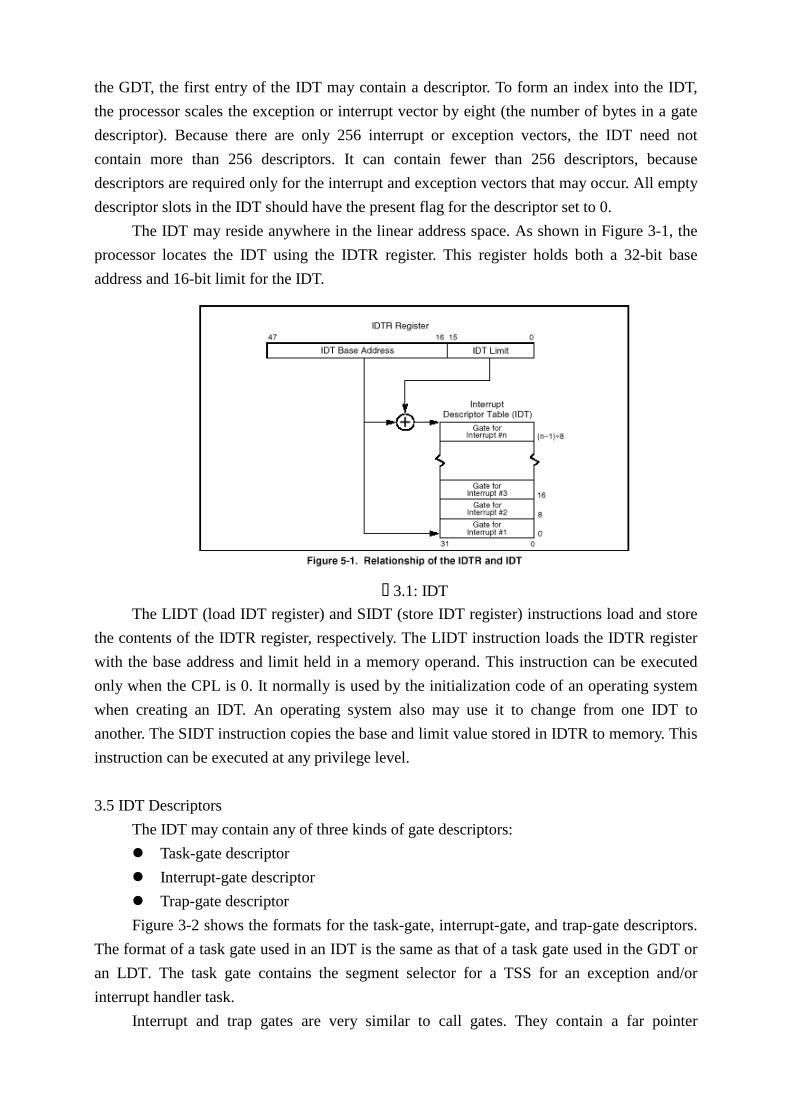
The IDT may reside anywhere in the linear address space. As shown in Figure 3-1, the
processor locates the IDT using the IDTR register. This register holds both a 32-bit base
address and 16-bit limit for the IDT.
� 3.1: IDT
The LIDT (load IDT register) and SIDT (store IDT register) instructions load and store
the contents of the IDTR register, respectively. The LIDT instruction loads the IDTR register
with the base address and limit held in a memory operand. This instruction can be executed
only when the CPL is 0. It normally is used by the initialization code of an operating system
when creating an IDT. An operating system also may use it to change from one IDT to
another. The SIDT instruction copies the base and limit value stored in IDTR to memory. This
instruction can be executed at any privilege level.
3.5 IDT Descriptors
The IDT may contain any of three kinds of gate descriptors:
z�Task-gate descriptor
z�Interrupt-gate descriptor
z�Trap-gate descriptor
Figure 3-2 shows the formats for the task-gate, interrupt-gate, and trap-gate descriptors.
The format of a task gate used in an IDT is the same as that of a task gate used in the GDT or
an LDT. The task gate contains the segment selector for a TSS for an exception and/or
interrupt handler task.
Interrupt and trap gates are very similar to call gates. They contain a far pointer

(segment selector and offset) that the processor uses to transfer of execution to a handler
procedure in an exception- or interrupt-handler code segment. These gates differ in the way
the processor handles the IF flag in the EFLAGS register.
� 3-2: IDT gate descriptors
� 3-3: Call-gate descriptor
3.6 Exception and Interrupt Handling
The processor handles calls to exception- and interrupt-handlers similar to the way it
handles calls with a CALL instruction to a procedure or a task. When responding to an
exception or interrupt, the processor uses the exception or interrupt vector as an index to a
descriptor in the IDT. If the index points to an interrupt gate or trap gate, the processor calls

the exception or interrupt handler in a manner similar to a CALL to a call gate. If index points
to a task gate, the processor executes a task switch to the exception- or interrupt-handler task
in a manner similar to a CALL to a task gate.
☞☞ Exception- or Interrupt-Handler Procedures An interrupt gate or trap gate references an exception- or interrupt-handler
procedure that runs in the context of the currently executing task (see Figure 3-4). The
segment selector for the gate points to a segment descriptor for an executable code
segment in either the GDT or the current LDT. The offset field of the gate descriptor
points to the beginning of the exception- or interrupt-handling procedure.
When the processor performs a call to the exception- or interrupt-handler
procedure, it saves the current states of the EFLAGS register, CS register, and EIP
register on the stack (see Figure 3-5). (The CS and EIP registers provide a return
instruction pointer for the handler.) If an exception causes an error code to be saved, it is
pushed on the stack after the EIP value.
If the handler procedure is going to be executed at the same privilege level as the
interrupted procedure, the handler uses the current stack.
If the handler procedure is going to be executed at a numerically lower privilege
level, a stack switch occurs. When a stack switch occurs, a stack pointer for the stack to
be returned to is also saved on the stack. (The SS and ESP registers provide a return
stack pointer for the handler.) The segment selector and stack pointer for the stack to be
used by the handler is obtained from the TSS for the currently executing task. The
processor copies the EFLAGS, SS, ESP, CS, EIP, and error code information from the
interrupted procedure’s s tack to the handler’s stack.
To return from an exception- or interrupt-handler procedure, the handler must use
the IRET (or IRETD) instruction. The IRET instruction is similar to the RET instruction
except that it restores the saved flags into the EFLAGS register. The IOPL field of the
EFLAGS register is restored only if the CPL is 0. The IF flag is changed only if the
CPL is less than or equal to the IOPL.
If a stack switch occurred when calling the handler procedure, the IRET
instruction switches back to the interrupted procedure’s stack on the return.
☞☞ Interrupt Tasks When an exception or interrupt handler is accessed through a task gate in the IDT,
a task switch results. Handling an exception or interrupt with a separate task offers
several advantages:
z�The entire context of the interrupted program or task is saved automatically.
z�A new TSS permits the handler to use a new privilege level 0 stack when
handling the exception or interrupt. If an exception or interrupt occurs when
the current privilege level 0 stack is corrupted, accessing the handler through
a task gate can prevent a system crash by providing the handler with a new

privilege level 0 stack.
z�The handler can be further isolated from other tasks by giving it a separate
address space. This is done by giving it a separate LDT.
�3-4: Exception- or Interrupt-Handler Procedure Call
�3-5: Stack usage of interrupt-handling procedures.

The disadvantage of handling an interrupt with a separate task is that the amount
of machine state that must be saved on a task switch makes it slower than using an
interrupt gate, resulting in increased interrupt latency.
A task gate in the IDT references a TSS descriptor in the GDT (see Figure 3-6). A
switch to the handler task is handled in the same manner as an ordinary task switch. The
link back to the interrupted task is stored in the previous task link field of the handler
task’s TSS. If an exception caused an error code to be generated, this error code is
copied to the stack of the new task.
�5-6: Interrupt task switch
���0HPRU\�0DQDJHPHQW �The memory management facilities of the Intel Architecture are divided into two parts:
segmentation and paging. Segmentation provides a mechanism of isolating individual code,
data, and stack modules so that multiple programs (or tasks) can run on the same processor
without interfering with one another. Paging provides a mechanism for implementing a
conventional demand-paged, virtual-memory system where sections of a program’s execution
environment are mapped into physical memory as needed. Paging can also be used to provide
isolation between multiple tasks.
As shown in Figure 4-1, segmentation provides a mechanism for dividing the
processor’s addressable memory space (called the linear address space) into smaller
protected address spaces called segments. Segments can be used to hold the code, data, and
stack for a program or to hold system data structures (such as a TSS or LDT). If more than
one program (or task) is running on a processor, each program can be assigned its own set of

segments. The processor then enforces the boundaries between these segments and insures
that one program does not interfere with the execution of another program by writing into the
other program’s segments.
� 4-1: Segmentation and Paging
All of the segments within a system are contained in the processor’s linear address
space. To locate a byte in a particular segment, a logical address (sometimes called a far
pointer) must be provided. A logical address consists of a segment selector and an offset. The
segment selector is a unique identifier for a segment. Among other things it provides an offset
into a descriptor table (such as the global descriptor table, GDT) to a data structure called a
segment descriptor. Each segment has a segment descriptor, which specifies the size of the
segment, the access rights and privilege level for the segment, the segment type, and the
location of the first byte of the segment in the linear address space (called the base address of
the segment). The offset part of the logical address is added to the base address for the
segment to locate a byte within the segment. The base address plus the offset thus forms a
linear address in the processor’s linear address space.
Paging supports a “virtual memory” environment where a large linear address space is
simulated with a small amount of physical memory (RAM and ROM) and some disk storage.
When using paging, each segment is divided into pages (ordinarily 4 KBytes each in size),
which are stored either in physical memory or on the disk. The operating system or executive
maintains a page directory and a set of page tables to keep track of the pages. When a
program (or task) attempts to access an address location in the linear address space, the
processor uses the page directory and page tables to translate the linear address into a physical
address and then performs the requested operation (read or write) on the memory location. If

the page being accessed is not currently in physical memory, the processor interrupts
execution of the program (by generating a page-fault exception). The operating system or
executive then reads the page into physical memory from the disk and continues executing the
program.
����3K\VLFDO�DGGUHVV�VSDFH �In protected mode, the Intel Architecture provides a normal physical address space of 4
Gbytes (232 bytes). This is the address space that the processor can address on its address bus.
This address space is flat (unsegmented), with addresses ranging continuously from 0 to
FFFFFFFFH. This physical address space can be mapped to read-write memory, read-only
memory, and memory mapped I/O. The memory mapping facilities described in this chapter
can be used to divide this physical memory up into segments and/or pages.
(Introduced in the Pentium Pro processor.) The Intel Architecture also supports an
extension of the physical address space to 236 bytes (64 GBytes), with a maximum physical
address of FFFFFFFFFH. This extension is invoked with the physical address extension (PAE)
flag, located in bit 5 of control register CR4.
����/RJLFDO�DQG�OLQHDU�DGGUHVVHV �At the system-architecture level in protected mode, the processor uses two stages of
address translation to arrive at a physical address: logical-address translation and linear
address space paging. A logical address consists of a 16-bit segment selector and a 32-bit
offset (see Figure 4-2). The segment selector identifies the segment the byte is located in and
the offset specifies the location of the byte in the segment relative to the base address of the
segment.
The processor translates every logical address into a linear address. A linear address is a
32-bit address in the processor’s linear address space. Like the physical address space, the
linear address space is a flat (unsegmented), 232 -byte address space, with addresses ranging
from 0 to FFFFFFFH. The linear address space contains all the segments and system tables
defined for a system.
To translate a logical address into a linear address, the processor does the following:
1. Uses the offset in the segment selector to locate the segment descriptor for the
segment in the GDT or LDT and reads it into the processor.
2. Examines the segment descriptor to check the access rights and range of the segment
to insure that the segment is accessible and that the offset is within the limits of the
segment.�3. Adds the base address of the segment from the segment descriptor to the offset to
form a linear address.�
Following are some related system registers and data structures:
☞Segment selectors

�4-2: Logical address to linear address translation
�4-3: Segment selector
A segment selector is a 16-bit identifier for a segment (see Figure 4-3). It does not
point directly to the segment, but instead points to the segment descriptor that defines
the segment. A segment selector contains the following items:
Index (Bits 3 through 15). Selects one of 8192 descriptors in the GDT or LDT. The
processor multiplies the index value by 8 (the number of bytes in a segment
descriptor) and adds the result to the base address of the GDT or LDT (from the
GDTR or LDTR register, respectively).
TI (table indicator) flag (Bit 2). Specifies the descriptor table to use: clearing this flag
selects the GDT; setting this flag selects the current LDT.
Requested Privilege Level (RPL) (Bits 0 and 1). Specifies the privilege level of the
selector. The privilege level can range from 0 to 3, with 0 being the most
privileged level.
The first entry of the GDT is not used by the processor. A segment selector that
points to this entry of the GDT (that is, a segment selector with an index of 0 and the TI
flag set to 0) is used as a “null segment selector.” The processor does not generate an
exception when a segment register (other than the CS or SS registers) is loaded with a
null selector. It does, however, generate an exception when a segment register holding a
null selector is used to access memory. A null selector can be used to initialize unused
segment registers. Loading the CS or SS register with a null segment selector causes a
general-protection exception (#GP) to be generated
☞Segment registers

To reduce address translation time and coding complexity, the processor provides
registers for holding up to 6 segment selectors (see Figure 4-4). Each of these segment
registers support a specific kind of memory reference (code, stack, or data). For
virtually any kind of program execution to take place, at least the code-segment (CS),
data-segment (DS), and stack-segment (SS) registers must be loaded with valid segment
selectors. The processor also provides three additional data-segment registers (ES, FS,
and GS), which can be used to make additional data segments available to the currently
executing program (or task).
For a program to access a segment, the segment selector for the segment must
have been loaded in one of the segment registers. So, although a system can define
thousands of segments, only 6 can be available for immediate use. Other segments can
be made available by loading their segment selectors into these registers during program
execution.
�4-4: Segment registers
Every segment register has a “visible” part and a “hidden” part. When a segment
selector is loaded into the visible part of a segment register, the processor also loads the
hidden part of the segment register with the base address, segment limit, and access
control information from the segment descriptor pointed to by the segment selector. The
information cached in the segment register (visible and hidden) allows the processor to
translate addresses without taking extra bus cycles to read the base address and limi t
from the segment descriptor. In systems in which multiple processors have access to the
same descriptor tables, it is the responsibili ty of software to reload the segment registers
when the descriptor tables are modified. If this is not done, an old segment descriptor
cached in a segment register might be used after its memory-resident version has been
modified.
☞Segment descriptors
A segment descriptor is a data structure in a GDT or LDT that provides the
processor with the size and location of a segment, as well as access control and status
information. Segment descriptors are typically created by compilers, linkers, loaders, or
the operating system or executive, but not application programs. Figure 4-5 ill ustrates
the general descriptor format for all types of segment descriptors.
The flags and fields in a segment descriptor are as follows:

�4-5: Segment descriptor
Segment limit field
Specifies the size of the segment. The processor puts together the two segment
limit fields to form a 20-bit value. The processor interprets the segment limit in one of
two ways, depending on the setting of the G (granularity) flag:
z�If the granularity flag is clear, the segment size can range from 1 byte to 1
MByte, in byte increments.
z�If the granularity flag is set, the segment size can range from 4 KBytes to 4
GBytes, in 4-KByte increments.
Base address fields
Defines the location of byte 0 of the segment within the 4-GByte linear address
space. The processor puts together the three base address fields to form a single 32-bit
value. Segment base addresses should be aligned to 16-byte boundaries.
Type field
Indicates the segment or gate type and specifies the kinds of access that can be
made to the segment and the direction of growth. The interpretation of this field
depends on whether the descriptor type flag specifies an application (code or data)
descriptor or a system descriptor.
S (descriptor type) flag
Specifies whether the segment descriptor is for a system segment (S flag is clear)
or a code or data segment (S flag is set).
DPL (descriptor privilege level) field
Specifies the privilege level of the segment. The privilege level can range from 0
to 3, with 0 being the most privileged level. The DPL is used to control access to the
segment.
P (segment-present) flag
Indicates whether the segment is present in memory (set) or not present (clear). If
this flag is clear, the processor generates a segment-not-present exception (#NP) when a

segment selector that points to the segment descriptor is loaded into a segment register.
Memory management software can use this flag to control which segments are actually
loaded into physical memory at a given time. It offers a control in addition to paging for
managing virtual memory.
D/B (default operation size/default stack pointer size and/or upper bound) flag
Performs different functions depending on whether the segment descriptor is an
executable code segment, an expand-down data segment, or a stack segment. (This flag
should always be set to 1 for 32-bit code and data segments and to 0 for 16-bit code and
data segments.)
z�Executable code segment. The flag is called the D flag and it indicates the
default length for effective addresses and operands referenced by instructions
in the segment. If the flag is set, 32-bit addresses and 32-bit or 8-bit operands
are assumed; if it is clear, 16-bit addresses and 16-bit or 8-bit operands are
assumed. The instruction prefix 66H can be used to select an operand size
other than the default, and the prefix 67H can be used select an address size
other than the default.
z�Stack segment (data segment pointed to by the SS register). The flag is
called the B (big) flag and it specifies the size of the stack pointer used for
implicit stack operations (such as pushes, pops, and calls). If the flag is set, a
32-bit stack pointer is used, which is stored in the 32-bit ESP register; if the
flag is clear, a 16-bit stack pointer is used, which is stored in the 16-bit SP
register. If the stack segment is set up to be an expand-down data segment
(described in the next paragraph), the B flag also specifies the upper bound of
the stack segment.
z�Expand-down data segment. The flag is called the B flag and it specifies the
upper bound of the segment. If the flag is set, the upper bound is FFFFFFFFH
(4 GBytes); if the flag is clear, the upper bound is FFFFH (64 KBytes).
G (granularity) flag
Determines the scaling of the segment limit field. When the granularity flag is
clear, the segment limit is interpreted in byte units; when flag is set, the segment limit is
interpreted in 4-KByte units.
Available and reserved bits
Bit 20 of the second doubleword of the segment descriptor is available for use by
system software; bit 21 is reserved and should always be set to 0.
☞Code- and Data-segment descriptor types
When the S (descriptor type) flag in a segment descriptor is set, the descriptor is
for either a code or a data segment. The highest order bit of the type field (bit 11 of the
second double word ofthe segment descriptor) then determines whether the descriptor is
for a data segment (clear) or a code segment (set).

For data segments, the three low-order bits of the type field (bits 8, 9, and 10) are
interpreted as accessed (A), write-enable (W), and expansion-direction (E). See Table
4-1 for a description of the encoding of the bits in the type field for code and data
segments.
�4-1
☞Segment descriptor types
When the S (descriptor type) flag in a segment descriptor is clear, the descriptor
type is a system descriptor. The processor recognizes the following types of system
descriptors:
z�Local descriptor-table (LDT) segment descriptor.
z�Task-state segment (TSS) descriptor.
z�Call-gate descriptor.
z�Interrupt-gate descriptor.
z�Trap-gate descriptor.
z�Task-gate descriptor.
These descriptor types fall into two categories: system-segment descriptors and
gate descriptors. System-segment descriptors point to system segments (LDT and TSS
segments). Gate descriptors are in themselves “gates,” which hold pointers to procedure
entry points in code segments (call, interrupt, and trap gates) or which hold segment
selectors for TSS’s (task gates). Tabl e 4-2 shows the encoding of the type field for
system-segment descriptors and gate descriptors.
☞Segment descriptor tables
A segment descriptor table is an array of segment descriptors (see Figure 4-6). A
descriptor table is variable in length and can contain up to 8192 (213 ) 8-byte descriptors.
There are two kinds of descriptor tables:
z�The global descriptor table (GDT)

�4-2
�4-6 GDT and LDT
z�The local descriptor tables (LDT)
Each system must have one GDT defined, which may be used for all programs
and tasks in the system. Optionally, one or more LDTs can be defined. For example, an
LDT can be defined for each separate task being run, or some or all tasks can share the
same LDT.

The GDT is not a segment itself; instead, it is a data structure in the linear address
space. The base linear address and limit of the GDT must be loaded into the GDTR
register.
The LDT is located in a system segment of the LDT type. The GDT must contain
a segment descriptor for the LDT segment. If the system supports multiple LDTs, each
must have a separate segment selector and segment descriptor in the GDT. The segment
descriptor for an LDT can be located anywhere in the GDT. An LDT is accessed with
its segment selector. To eliminate address translations when accessing the LDT, the
segment selector, base linear address, limit, and access rights of the LDT are stored in
the LDTR register
�����3DJLQJ��/LQHDU�DGGUHVV�WR�SK\VLFDO�DGGUHVV� �
When paging is used, the processor divides the linear address space into fixed-size
pages (generally 4 KBytes in length) that can be mapped into physical memory and/or disk
storage. When a program (or task) references a logical address in memory, the processor
translates the address into a linear address and then uses its paging mechanism to translate the
linear address into a corresponding physical address. If the page containing the linear address
is not currently in physical memory, the processor generates a page-fault exception (#PF). The
exception handler for the page-fault exception typically directs the operating system or
executive to load the page from disk storage into physical memory (perhaps writing a
different page from physical memory out to disk in the process). When the page has been
loaded in physical memory, a return from the exception handler causes the instruction that
generated the exception to be restarted. The information that the processor uses to map linear
addresses into the physical address space and to generate page-fault exceptions (when
necessary) is contained in page directories and page tables stored in memory.
Paging is controlled by three flags in the processor’s control registers:
z�PG (paging) flag, bit 31 of CR0: The PG flag enables the page-translation
mechanism.
z�PSE (page size extensions) flag, bit 4: The PSE flag enables large page sizes:
4-MByte pages or 2-MByte pages (when the PAE flag is set). When the PSE flag is
clear, the more common page length of 4 KBytes is used.
z�PAE (physical address extension) flag, bit 5 of CR4: The PAE flag enables 36-bit
physical addresses.�
The information that the processor uses to translate linear addresses into physical
addresses (when paging is enabled) is contained in four data structures:
z�Page directory: an array of 32-bit page-directory entries (PDEs) contained in a
4-Kbyte page. Up to 1024 page-directory entries can be held in a page directory.
z�Page table: an array of 32-bit page-table entries (PTEs) contained in a 4-KByte
page. Up to 1024 page-table entries can be held in a page table. (Page tables are not

used for 2-MByte or 4-MByte pages. These page sizes are mapped directly from
one or more page-directory entries.)
z�Page: a 4-KByte, 2-MByte, or 4-MByte flat address space.
z�Page-Directory-Pointer Table: an array of four 64-bit entries, each of which points
to a page directory. This data structure is only used when the physical address
extension is enabled.�
Figure 4-7 shows the page directory and page-table hierarchy when mapping linear
addresses to 4-KByte pages. The entries in the page directory point to page tables, and the
entries in a page table point to pages in physical memory. This paging method can be used to
address up to 220 pages, which spans a linear address space of 232 bytes (4 GBytes).
� 4-7: Linear address to physical address translation
To select the various table entries, the linear address is divided into three sections:
z�Page-directory entry: Bits 22 through 31 provide an offset to an entry in the page
directory. The selected entry provides the base physical address of a page table.
z�Page-table entry: Bits 12 through 21 of the linear address provide an offset to an
entry in the selected page table. This entry provides the base physical address of a
page in physical memory.�z�Page offset: Bits 0 through 11 provides an offset to a physical address in the page.�
Figure 4-8 shows the format for the page-directory and page-table entries when 4-Kbyte
pages and 32-bit physical addresses are being used. The functions of the flags and fields in the
entries are as follows:
Page base address, bits 12 through 32
(Page-table entries for 4-KByte pages.) Specifies the physical address of the first
byte of a 4-KByte page. The bits in this field are interpreted as the 20 most-significant
bits of the physical address, which forces pages to be aligned on 4-KByte boundaries.
(Page-directory entries for 4-KByte page tables.) Specifies the physical address of

the first byte of a page table. The bits in this field are interpreted as the 20
most-significant bits of the physical address, which forces page tables to be aligned on
4-KByte boundaries.
�4-8: Page-Directory and Page-Table Entries
Present (P) flag, bit 0
Indicates whether the page or page table being pointed to by the entry is currently
loaded in physical memory. When the flag is set, the page is in physical memory and
address translation is carried out. When the flag is clear, the page is not in memory and,
if the processor attempts to access the page, it generates a page-fault exception (#PF).
Read/write (R/W) flag, bit 1
Specifies the read-write privileges for a page or group of pages (in the case of a
page-directory entry that points to a page table). When this flag is clear, the page is read
only; when the flag is set, the page can be read and written into.
User/supervisor (U/S) flag, bit 2
Specifies the user-supervisor privileges for a page or group of pages (in the case
of a page-directory entry that points to a page table). When this flag is clear, the page is
assigned the supervisor privilege level; when the flag is set, the page is assigned the
user privilege level.
Page-level write-through (PWT) flag, bit 3
Controls the write-through or write-back caching policy of individual pages or
page tables. When the PWT flag is set, write-through caching is enabled for the

associated page or page table; when the flag is clear, write-back caching is enabled for
the associated page or page table.
Page-level cache disable (PCD) flag, bit 4
Controls the caching of individual pages or page tables. When the PCD flag is set,
caching of the associated page or page table is prevented; when the flag is clear, the
page or page table can be cached. This flag permits caching to be disabled for pages that
contain memory-mapped I/O ports or that do not provide a performance benefit when
cached.
Accessed (A) flag, bit 5
Indicates whether a page or page table has been accessed (read from or written to)
when set. Memory management software typically clears this flag when a page or page
table is initially loaded into physical memory. The processor then sets this flag the first
time a page or page table is accessed. This flag is a “sticky” flag, meaning that once set,
the processor does not implicitly clear it. Only software can clear this flag. The accessed
and dirty flags are provided for use by memory management software to manage the
transfer of pages and page tables into and out of physical memory.
Dirty (D) flag, bit 6
Indicates whether a page has been written to when set. (This flag is not used in
page-directory entries that point to page tables.) Memory management software
typically clears this flag when a page is initially loaded into physical memory. The
processor then sets this flag the first time a page is accessed for a write operation. This
flag is “sticky,” meaning that once set, the processor does not implicitly clear it. Only
software can clear this flag. The dirty and accessed flags are provided for use by
memory management software to manage the transfer of pages and page tables into and
out of physical memory.
Page size (PS) flag, bit 7
Determines the page size. This flag is only used in page-directory entries. When
this flag is clear, the page size is 4 KBytes and the page-directory entry points to a page
table. When the flag is set, the page size is 4 MBytes for normal 32-bit addressing (and
2 MBytes if extended physical addressing is enabled) and the page-directory entry
points to a page. If the page-directory entry points to a page table, all the pages
associated with that page table will be 4-Kbyte pages.
Global (G) flag, bit 8
(Introduced in the Pentium Pro processor.) Indicates a global page when set.
When a page is marked global and the page global enable (PGE) flag in register CR4 is
set, the page-table or page-directory entry for the page is not invalidated in the TLB
when register CR3 is loaded or a task switch occurs. This flag is provided to prevent
frequently used pages (such as pages that contain kernel or other operating system or
executive code) from being flushed from the TLB. Only software can set or clear this
flag. For page-directory entries that point to page tables, this flag is ignored and the

global characteristics of a page are set in the page-table entries.
Reserved and available-to-software bits
In a page-table entry, bit 7 is reserved and should be set to 0; in a page-directory
entry that points to a page table, bit 6 is reserved and should be set to 0. For a
page-directory entry for a 4-MByte page, bits 12 through 21 are reserved and must be
set to 0, for Intel Architecture processors through the Pentium II processor. For both
types of entries, bits 9, 10, and 11 are available for use by software. (When the present
bit is clear, bits 1 through 31 are available to software.) When the PSE and PAE flags in
control register CR4 are set, the processor generates a page fault if reserved bits are not
set to 0.