INTEGRATION OF SUBSTATION DATA - Home - CIMugcimug.ucaiug.org/KB/Knowledge Base/Integration of...
34
INTEGRATION OF SUBSTATION DATA By: SISCO, Inc. www.sisconet.com ABSTRACT This paper discusses how the use of standard data models and services can facilitate integration of existing substation related data. The goal is to provide a unified view of substation operating and asset data to facilitate higher level substation related analysis. The primary benefit of using standard data models and services to access existing substation devices and related applications is that it enables higher level analysis applications to interact with substation related data sources in an efficient, structured, and unambiguous fashion independent of existing device physical attributes as well as communications and application interfaces. The efficient migration of devices and applications into a unified analysis infrastructure is key to reliable and profitable utility operation.
Transcript of INTEGRATION OF SUBSTATION DATA - Home - CIMugcimug.ucaiug.org/KB/Knowledge Base/Integration of...

INTEGRATION OF SUBSTATION DATA
By: SISCO, Inc. www.sisconet.com
ABSTRACT
This paper discusses how the use of standard data models and services can facilitate integration of existing substation related data. The goal is to provide a unified view of substation operating and asset data to facilitate higher level substation related analysis.
The primary benefit of using standard data models and services to access existing substation devices and related applications is that it enables higher level analysis applications to interact with substation related data sources in an efficient, structured, and unambiguous fashion independent of existing device physical attributes as well as communications and application interfaces. The efficient migration of devices and applications into a unified analysis infrastructure is key to reliable and profitable utility operation.

Integration of Substation Data Version 6.0
1. SUMMARY This paper discusses integration of existing substation devices with other information sources to facilitate the implementation of advanced power system applications. The goal of this architecture is not to support the hard real-time control of substation equipment that typically occurs between substation devices. Rather, it is to provide a migration strategy so that existing equipment and control center applications can be operated in a more profitable and reliable manner.
1.1 Unified Data Access Most substation data comes from substation devices. All substation devices have a common set of functionality – they create, consume, and/or contain data; they initiate and/or respond to control signals; and they interact closely with their local physical environment using this functionality.
This common set of functionality can be represented architecturally in terms of data (what) and services (how). From the data point of view, any device can be represented by a information model. The data elements within the device can be named, have a type, and have a well defined meaning within the context of the device’s application. The communications infrastructure provides the mechanisms necessary to interact with the information model through a set of services. Such services can be as simple as read, write, and report on change. Higher-level services may be derived from these to provide functionality such as file transfer, information model discovery, and numerous device configuration services. While internally every device may implement a diverse set of data models and access methods, externally unified access can be achieved via the deployment of a common information model and common services.
Data Client (e.g. asset life cycle optimization application)
Devices accessed in a uniform way in terms of data(common information model) and mechanisms
(common services)
Substation Device Integration
Infrastructure
61850 devices
60870-5/DNP devices
Devices supporting
other protocols
Hard wired devices
60870-5 /DNP/61850
RTU
Figure 1-1 Integration of New and Legacy Devices
In Figure 1-1 above, information from field devices that may natively use various low level protocols is exposed using the common information model and services approach.
© 2006 SISCO, Inc. 2

Integration of Substation Data Version 6.0
In addition to device data, comprehensive substation analysis needs power system network and asset management application information. Similar to device data, power system network and asset applications can be accessed via a common information model. As with substation devices, the communications infrastructure provides the mechanisms necessary to interact with new and legacy applications through a set of services.
The following figure illustrates substation devices as well as power system network/asset applications, that each may implement various native data models and access mechanisms internally, but are integrated using a single unified information model and common services. Only when all of the related information is fused together can an operator have a clear picture of what the state of the system is before initiating an action in a cost effective and safe manner that is consistent with the higher-level mission of the overall enterprise.
Data Client (e.g. asset life cycle optimization application)
Device and application information accessed in a uniform way in terms of data (common information model) and mechanisms (common services)
Substation Information Integration Infrastructure
Power System
Network Applications
Devices
Asset Management Applications
Figure 1-2 Integration of New and Legacy Devices and Applications
1.2 Benefits The primary benefit of unified access to substation devices and power system network/asset management applications through the use of a common information model and services is that it enables higher level applications to interact with devices and other applications in an efficient, structured, and unambiguous fashion independent of the native application interfaces or the device’s physical attributes and communications interfaces. Because detailed knowledge of the inner workings of each device and application is hidden, devices and applications do not need to be replaced in order to be integrated. Additionally a utility can change out individual devices and applications as technology and functional requirements change with little or no impact on the analysis level. Such a non-intrusive integration strategy allows existing devices and applications to evolve independently takes maximum advantage of past investment while also providing a path to the future.
The ultimate benefit of a unified architecture is higher reliability at lower cost (implementation and maintenance). Higher reliability via increase visibility into system operation and lower cost via increased asset utilization.
© 2006 SISCO, Inc. 3

Integration of Substation Data Version 6.0
Without a common information model and services, device and application data integration becomes chaotic. In fact, this is the situation many systems face today. Additional systems, gateways, interfaces, and other patches have been deployed to try and address the need for integrating substation data and applications, but this increases complexity and cost. Since overall integration of power system management and the implementation of system reliability analysis and other analysis applications depends upon the underlying devices and applications that make up the system, the efficient and cost effective integration of these devices and applications into the enterprise is key to its reliable and profitable operation.
2. ENGINEERING ANALYSIS
2.1 Joining Environments Integration of substation data can be seen as joining a series of environments each with non-mutually exclusive sets of requirements. Each environment is associated with a location or network where one or more of the information exchanges of power system functions have essentially the same technical requirements, including:
• Configuration requirements
• Quality of service requirements
• Information security requirements
• Data management and exchange requirements
This paper discusses the integration of two environments: The substation environment and the operations environment. The substation environment consists of real-time or near real-time oriented devices running within the substation. Substation devices includes both primary equipment (breakers, transformers, etc.) and secondary devices (RTU’s, IED’s, etc.).
The operations environment consists of applications running in the control/operations center. Operations related applications include:
• Geographic Information Systems (GIS)
• Asset/Work Management Systems (AMS/WMS)
• Supervisory Control And Data Acquisition (SCADA)
• Energy Management Systems (EMS)/Distribution Management Systems (DMS)
• Outage Management Systems (OMS)
• Customer Information Systems (CIS)
© 2006 SISCO, Inc. 4

Integration of Substation Data Version 6.0
2.1.1 The Substation Environment Substation environment integration typically focuses on the integration of device wire protocols. While many communication protocols are used in substations, this paper more narrowly examines1:
• The IEC’s 60870-5: Telecontrol Protocols and the DNP User Group’s Distributed Networking Protocol Number 3 (DNP3) series of standards related to data communication protocols for IED’s. For the sake of brevity, this paper will refer only to DNP3 as these two protocols are functionally very similar.
• The IEC’s 61850: Communication Networks and Systems in Substations for substation automation utilizing modern high-speed networking technology.
DNP3 specifies a set of communication protocols for point-to-point serial and Ethernet networks using TCP/IP or UDP/IP. IEC61850 specifies a set of communications requirements for substations, a technology neutral service model for commonly required communications substation services, a technology neutral model for substation data objects, a device configuration language based on XML, and a mapping of these technology neutral models to the Manufacturing Message Specification (MMS per ISO9506) application layer protocol running over TCP/IP based Ethernet networks.
The use of DNP3 and IEC61850 is not mutually exclusive. Each was designed to be optimized for a given set of requirements. This does not mean that neither can be used outside of its optimal space nor does it mean that only one or the other can be used at any given time. The byte efficiency of DNP3 makes it an excellent choice for bandwidth constrained applications in distribution systems like pole-top devices or where existing systems already provide DNP3 connectivity. The high-level object models and high-performance services of IEC61850 will make it an excellent choice where large numbers of devices must be configured, where the number of communicating entities is difficult to fix or is constantly changing, and where changes in device configuration frequently causes maintenance problems in existing applications. Any well designed system will utilize each/both DNP3 and IEC61850 as appropriate to maximize the benefits and minimize the costs for implementing the systems needed by users.
2.1.2 The Operations Environment Operations environment integration typically focuses on standard application services. This paper examines:
• The IEC’s 61970: EMS-API set of standards for energy management systems and operations application integration.
• The IEC’s 619698: System Interfaces For Distribution Management set of standards for inter application messaging.
IEC61970 and IEC61968 are complementary in that both standards have defined utility data semantics for the IEC Common Information Model (IEC61970-3 and 61968-11). 1 The authors believe that this document’s discussion of DNP3 can be applied to many other legacy RTU/SCADA protocols.
© 2006 SISCO, Inc. 5

Integration of Substation Data Version 6.0
The difference between the two is that 61970 has also defined a set of services for exchanging data (IEC61970-4). IEC 61968 has defined the nouns (e.g. “Work Order”) the verbs (e.g. “Create”) and the message contents for messages exchanged between systems (IEC61968-1-10). IEC61968 messages are independent of data exchange mechanisms.
Using these technologies, applications connect to an infrastructure either directly, if they natively support the standard object models and interfaces, or via a wrapper that converts native semantics and access mechanisms to the standard ones as shown below:
WrapperWrapperWrapper
GIS
AMS/WMS
EMS or DMS Cust. Info.System
OMSArchive
61970/61968 Based Integration infrastructure 61970/61968 Based Integration infrastructure
Figure 2-1: Operations Application Integration
Using this approach each application’s internal data model and data access mechanisms can evolve independently.
Comparing 61850 to 61970, one can see a similar document structure. Figure 2-2 provides an overview of the domains of the two standards.
Object ModelsIEC61850-7-3 & 7-4
IEC60870-5/DNP
Service ModelsIEC61850-7-2
IEC60870-5/DNP
Communication Profiles & Mapping
IEC61850-8 & 9
Substation Communications
Object ModelsIEC61970-3
Service ModelsIEC61970-4
IEC61968 - 2-11
Technology Profiles & Mapping
IEC61970-5
Operations Communications
Figure 2-2: Non Integrated IEC61850 and IEC61970 Communication Models
The next two sections provide greater detail on these object models and services.
© 2006 SISCO, Inc. 6

Integration of Substation Data Version 6.0
2.2 Information/Object Models In order to precisely describe the meaning of a set of terms, engineers often create an information model2. An information model describes the schema for a collection of related real world objects in terms of classes, attributes and relationships and provides unique names and definitions for each object type. This section describes what an information model is and how it is typically used as well some example information models.
2.2.1 DNP and 61850 Object Models Both IEC61850 and DNP3 define various object types for representing power system data. The DNP3 object model is based on a traditional remote terminal unit (RTU) device model. A traditional RTU is a general purpose device capable of collecting I/O signals in a variety of formats (digital, analog, state, etc.) and communicating those I/O signals using a SCADA protocol such as DNP3. Because RTU’s were traditionally general purpose, it was the user or system engineer that determined the specific function a specific I/O point represented when they wired that I/O point within the substation. For example, an RTU would have a variety of analog and digital inputs. It was typically the user that wired those inputs to specific current and voltage transformers or specific breakers that created the “mapping” between these I/O points and specific functions in the substation. Therefore, when the engineer wanted to access the I/O for a given bus voltage by communicating to the RTU from a remote site via some protocol, they would have to have either a wiring diagram or “tag database” that described where the desired voltage was wired into the RTU in order to access that I/O point via the RTU protocol.
The DNP3 data model is based on a similar structure. A DNP3 object description is comprised of three different parts:
• Object Number. The object number specifies the type of data point using a numerical value. For example, object number = 1 would represent a Binary Input Static data point, object number = 2 would represent a Binary Input Event data point, and so on.
• Variation Number. The variation number specifies which optional parameters would be present for a given data point of a specific object number. For instance, variation number = 1 would mean that the data point included status, variation number = 2 meant that the data point did not include status, and so on.
• Index Number. The index number refers to a specific instance of a DNP object and variation. For instance, if a device supported 16 binary input static objects, the index number to access one of these was 0-15.
• Device Profile. In addition to the description of the data points as defined above, the DNP Users Group also specified device profiles for common devices that specified which DNP objects should be implemented for a given type of device
2 For historical reasons, substation standards have used the term “object model” while IT standards have used the term “information model”. Both terms have essentially the same meaning and this paper treats these terms as synonyms.
© 2006 SISCO, Inc. 7

Integration of Substation Data Version 6.0
with recommendations for which object and variation numbers should be used for various types of signals that are commonly needed in these applications.
Note that the device profile associated with each I/O point is not exchanged (carried on the wire). As described above, the mapping between I/O points and devices must be maintained in a separate document or tag database.
IED IED IED
Driver 1 Driver 2 Driver 3
Application 1 Application 2
Tag Data Base
Legacy ElectroMech.
RTU
?
ExternalApplications
Figure 2-3: Legacy Substation Architecture
The result is that DNP3 specifies a broad set of data objects and device types sufficient to provide interoperability for a large number of applications and device types in power systems. Additional profiles are added as needed by the user community. Furthermore, the use of small 8-bit numbers to represent object and variation types and compact index numbers provided a very byte-efficient mechanism for specifying a data point. This allows DNP3 to maximize the number of data points that could be fit into a single DNP3 data frame. As described earlier, this byte efficiency was critical to the effectiveness of DNP3 as a solution for low-bandwidth serial links.
The IEC61850 data model is an object oriented model that not only defines the basic data types for common data points, but also rigorously defines the naming conventions used and how the data is organized into functional groupings called logical nodes. IEC61850 does not use compact numbers to describe data points. Instead, IEC61850 uses names that specify a fixed hierarchical organization for the data to describe each data object. The name specifies not only the way you access the data point via the protocol, but it also defines its functional characteristic within the device. In other words, because device modeling is carried on the wire, the engineer can automatically determine that a given point is a voltage without having to know how the device is wired. Therefore, a separately maintained tag database is not required. That the IEC61850 wire protocol supports embedded device modeling is key to lowering support and maintenance costs.
© 2006 SISCO, Inc. 8

Integration of Substation Data Version 6.0
61850 Network
61850IE
Substation and Control Center Applications
61850IED
61850IEDD
Figure 2-4: IEC61850 Network Architecture
The IEC61850 data model consists of the following concepts:
• Logical Device. The IEC61850 object model enables a single physical device to represent data for multiple logical devices such as might exist in a data concentrator application. This name is typically defined by the user or supplier. IEC61850 requires at least one logical device with a name of “LD0” to be present to hold data common to all logical devices such as device identity information.
Physical Device(network address)
Logical Device(e.g. Relay1)
MMXU1 MMXU2
MXMX
AV
Logical Nodes
Functional Constraints
“Relay1/MMXU2.MX.A” =Feeder #2 Current Measurements
Figure 2-5 IEC61850 Object Model
• Logical Node. Specifies a grouping of data objects that are functionally related.
For instance, measurements are contained in logical nodes with the name “MMXU”, data related to a switch controller function will be contained in logical nodes with the name “CSWI”, breaker data will be contained in a logical node named “XCBR”, and so on. Multiple instances of the same logical node are
© 2006 SISCO, Inc. 9

Integration of Substation Data Version 6.0
delineated by a suffix number (MMXU1, MMXU2, etc.). Logical nodes that are related to each other (the switch controller (CSWIx) associated with a given breaker (XCBRx)) can be associated to each other in the name using a user defined prefix (e.g. “bus1XCBR1” and “bus1CSWI1”).
• Functional Constraint. This is used to group together data attributes of a data object with similar functions within the logical node. For instance, “MX” designates measurements and “DC” designates descriptions, etc.
• Data Object. The data object name specifies the data desired. For instance, “PhV” specifies ground to phase voltage and “A” specifies current, etc.
• Attributes. These specify the individual elements that comprise a data object. For instance, “PhsA.cVal.mag.f” specifies the current RMS floating point value for phase A in a wye-connected measurement, “q” specifies quality flags, “t” specifies the time stamp, etc. The IEC61850 standard defines the data types (integer, floating point, binary, time, etc.) for all allowable attributes.
Per IEC61850, to create an object name you would take each element from the Logical Node down in the hierarchy separated by period (“.”). Therefore, the floating point value of the phase A voltage in the first measurement unit of a given device would be: MMXU1.MX.PhV.PhsA.cVal.mag.f. A power system engineer familiar with the IEC61850 naming convention can determine which data point contains the data they are interested in by examining the same name that is used to access the data via the protocol. The name for the same functional objects is mostly the same in any given device regardless of the brand or type of device.
Brand Y: Differential RelayBrand X: Instantaneous Overcurrent Relay
Relay 1
PIOC MeasurementsMMXU1
SG CO A PhV
Relay 2
PDIF MeasurementsMMXU1
SG CO A PhV
MMXV1.PhV.phsA.Cval.mg.f[MX]
phsA
Cval
mg
f[MX]
phsA
Cval
mg
f[MX]
Figure 2-6 IEC61850 View of Devices
© 2006 SISCO, Inc. 10

Integration of Substation Data Version 6.0
Additionally, IEC61850 includes a Substation Configuration Language (SCL per IEC61850-6) that can be used to express the configuration of all the data objects in a given device using XML. An SCL file will contain a description of all the logical devices, logical nodes, etc. that are defined for a given device. The SCL file can be used for many purposes that can significantly lower costs and improve productivity including: enabling users to create specifications for devices that can be used for RFP’s to ensure the equipment they purchase meets their functional requirements, automated tools can be developed to automatically configure devices with specific objects, configuration information on devices can be exchanged among devices improving the interchangeability of devices and applications, and many other future uses limited only by the creativity of users and suppliers. Importantly, some information contained in an SCL file will often not reside in a device and therefore is not accessible via IEC61850 wire protocols.
As can be seen, IEC61850 provides a flexible model that can contain rich device semantics. In fact the IEC61850 object model can be used to ‘wrap’ a DNP network with added semantics as shown below:
DNP Device A
DNP Device B
Example DNP Points
Point 1
Point 2
Point 3
Point 1
Point 2
Point 3
Map individual DNP points to
elements in a rich 61850 model in a
tag database
Example 61850 Object Model
Relay 1
MeasurementsMMXU1
A PhV
phsA
Cval
mg
f[MX]
phsA
Cval
mg
f[MX]
phsA
Cval
mg
f[MX]
phsA
Cval
mg
f[MX]
phsA
Cval
mg
f[MX]
phsA
Cval
mg
f[MX]
Figure 2-7: Mapping a DNP3 Device Points into an IEC61850 Model
The diagram illustrates for example, how a DNP3 network can be exposed using an IEC 61850 server gateway. However as shown below, it is important to recognize that
© 2006 SISCO, Inc. 11

Integration of Substation Data Version 6.0
accessing DNP3 via an IEC61850 gateway does not require replacing DNP3 devices or networks.
61850 Network
61850IED
61850IED
61850IED DNP/61850
Gateway
DNPIED
DNPIED
DNPIED
Legacy Devices
61850 Substation and Control Center Applications
LogicalDevice
LogicalDevice
LogicalDevice
Tag Data Base
Figure 2-8: Gateway for DNP3 Device Points into an IEC61850 Network
In the diagram above, 61850 is used to communicate within the substation as well as from the substation to the control center. Wrapping a DNP3 network with IEC61850 gateway allows the user to realize the benefits of a rich object model and object model based tools without abandoning past investment.
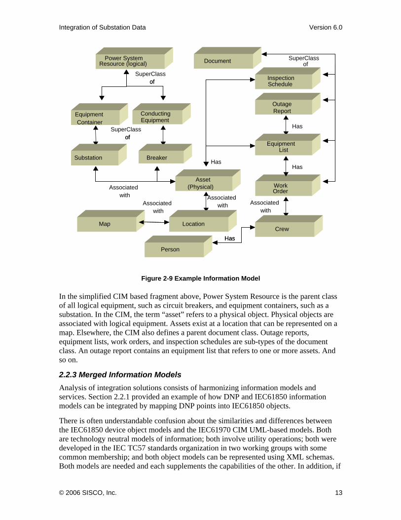
2.2.2 Common Information Model The EPRI/IEC Common Information Model (CIM) describes data typically used in a utility’s operational systems. The diagram below illustrates a simplified fragment of the CIM.
© 2006 SISCO, Inc. 12
Integration of Substation Data Version 6.0
Figure 2-9 Example Information Model
In the simplified CIM based fragment above, Power System Resource is the parent class of all logical equipment, such as circuit breakers, and equipment containers, such as a substation. In the CIM, the term “asset” refers to a physical object. Physical objects are associated with logical equipment. Assets exist at a location that can be represented on a map. Elsewhere, the CIM also defines a parent document class. Outage reports, equipment lists, work orders, and inspection schedules are sub-types of the document class. An outage report contains an equipment list that refers to one or more assets. And so on.
2.2.3 Merged Information Models Analysis of integration solutions consists of harmonizing information models and services. Section 2.2.1 provided an example of how DNP and IEC61850 information models can be integrated by mapping DNP points into IEC61850 objects.
There is often understandable confusion about the similarities and differences between the IEC61850 device object models and the IEC61970 CIM UML-based models. Both are technology neutral models of information; both involve utility operations; both were developed in the IEC TC57 standards organization in two working groups with some common membership; and both object models can be represented using XML schemas. Both models are needed and each supplements the capabilities of the other. In addition, if
Breaker
Equipment Container
Power System
Asset
Substation
Location
SuperClass of
Has
Has
Associated with
Associated with
SuperClassof
Map
Document
Outage
Inspection
Equipment
Work Order
SuperClass of
Has
Crew
Associated with
Person
Associated with
Has
Breaker
Equipment Container
Power System Resource (logical)
Asset(Physical)
Substation
Conducting Equipment
Location
of
of
Map
Document
Inspection Schedule
Outage Report
Equipment List
Crew
Person
Has
© 2006 SISCO, Inc. 13

Integration of Substation Data Version 6.0
both are implemented in a utility, they must interface with each other and function as an integrated whole.
The IEC TC57 has in fact undertaken to harmonize the two models as illustrated in Figure 2-.
Substation(f rom Co re )
VoltageLevel(from Core )
1 0..n1 0..n
Bay(from Core )
0.. 1 0.. n0.. 1 0.. n
Trans formerW inding(f rom W i res)
PowerTransformer(f rom W i res)
1..n
1
1..n
1
Equipment(from Core )
EquipmentContainer(from Core )
0..10..n 0..10..n
ConductingEquipment(from Core )
ConnectivityNode(f rom T o po logy )0..n1 0..n1
SubEquipment
LNode Container Data
LDeviceServer 3..*3..*IE D 0.. *1 0.. *1
Term inal(from Core )
0..n1 0..n1
0..n
0..1
0..n
0..1
PowerSystemResource(from Core )
Measu rem ent Va lue(f rom M eas)
Dat aA tt ribut e
1.. *1.. *
0..*
0..1
0..*
0..1
FunctionContainer
SubEquipmentContainer0..n0..n
MeasurementType(f rom M eas)
Measurement(f rom M eas)
0..n
0..1
0..n
0..1
0..1
0..n
0..1
0..n
1..n
1
1..n
1
0.. n
1
0.. n
1
SubFunction
Function
0..n0..n
0..n0..n
Gene ralEquip ment
0..*
0..*
0..*
0.. *
0..*
0..*
0.. *
0..*
LNode
0..*0..*
0..*0..*
1 .. *1 .. *
LNClass
10..*
10..*
61970 CIM shown in yellow
61850 extensions shown in green
Figure 2-10 Proposed UML based Harmonization of IEC61850 and IEC61970 Information Models
In this on-going harmonization work, two use cases have been identified as being important in illustrating the key harmonization issues:
• Retrofit of the equipment in a substation with the addition of a new line and transformer
• Real-Time information exchange between IEC61850 devices and the Control Center / Office
© 2006 SISCO, Inc. 14

Integration of Substation Data Version 6.0
The first use case assumes the use of the 61850 Substation Configuration Language (SCL) in the substation and also addresses harmonization between SCL and the CIM XML. While both SCL and CIM XML use XML, how power systems are modeled in each differ. Some preliminary work has addressed harmonization of the CIM and 61850 models. However, it is not clear if harmonization should be done by creating an SCL sub-model in the CIM UML such as that shown in Figure 2-16 or for example by the use of an XML dialect for management of ontologies such as OWL.
The second use case addresses a secondary “conflict” which is that the CIM defines all measurements as “PowerSystemResource” combined with a “MeasurementType” with no further clarification, while IEC61850 defines each value with a unique name. Although not formalized yet, the solution could to be to use the CIM AliasName in the MeasurementType CIM class to refer to the IEC61850 names.
The main problem, therefore, is mapping the data elements in the IED’s to “well-known” object names. IEC61850 performs this mapping to IEC61850 object models at the device level, while IEC61970 needs to perform this mapping to the CIM power resource object model in the control center. Since these are different mappings, they need to be harmonized.
Two UML associations described in the proposed harmonization of IEC61850 and IEC61970 information models are the key. The inheritance association between IEC61970 Equipment and IEC61850 GeneralEquipment allows the extension of a CIM device with IEC61850 device information. The association between IEC61970 Measurement and the IEC61850 DataAttribute allows us to map CIM measurements to IEC61850 object model values. DNP3 is not as simple to map because it uses simple objects that do not provide self-description.
It is clear that one of the main limitations of a DNP3 network is the limited amount of metadata that can be associated with a DNP3 device or measurement point. The proposed solution in this example is to present DNP3 data within a namespace presented by a GID server. Ideally, this namespace would be compatible with not only IEC61850, but also IEC61970 CIM Power System models. In other words, the sparse DNP3 model is decorated with rich IEC61850/61970 metadata so that the DNP3 data is made more meaningful to people and applications.
Since IEC IEC61970 defines a CIM set of packages which provide a logical view of the different aspects of Energy Management System information, the integration of legacy DNP3 based devices requires the mapping of the DNP3 points into the CIM object models.
2.3 Services Accessing utility devices and applications via a set of standard services allows components to be treated as black boxes. This section describes how common services can be used to access all substation data.
© 2006 SISCO, Inc. 15

Integration of Substation Data Version 6.0
2.3.1 61850 and DNP3 Service Models The services supported by DNP3 can be seen as a subset of that offered by IEC61850. This is not surprising since both are intended for similar applications in substation automation. In several areas where either DNP3 or IEC61850 has a capability not supported by the other, it is still possible to implement these services by combining other services. For instance, event logs can be implemented using files in DNP3 even though the DNP3 standard does not specify how to implement event logs. While the advantage of having the standard define these capabilities directly might be lost, the basic functionality is still available3.
YES***-Peer-to-Peer Messaging (GOOSE/GSSE)
YES**Substation Configuration Language (XML)
YESYESSubstitution (Forcing)
YES**Object Discovery
YES***-Sampled Measured Values (SMV)
YES*Event Logs
*YESStart/Stop
YESYESFiles
YES*Enhanced Control (with Reports)
YESYESControl (SBO and Direct)
YESYESReporting
YESYESRead/Write
IEC61850DNP3Service Description
* Not in the standard, but can be implemented** Under development*** Not possible to directly expose stream using GID interfaces
Table 2-1 Service Comparison
3 There are services that IEC61850 offers that cannot be practically supported using the current version of DNP3. These services include object discovery, Substation Configuration Language (SCL), GOOSE, GSSE, and SMV. Because these high-level (object discovery) or very high-performance (GOOSE, GSSE, and SMV) services were not practical for low-bandwidth serial link applications, they were never a part of DNP3’s origins and, therefore, were not available for the LAN based profiles that were developed for DNP3. There are work items within the DNP Users Group to develop a mapping between the technology neutral models of IEC61850 to DNP. However, such a mapping would require protocol changes to support these additional services that could not be implemented using the DNP3 protocol as it is defined today.
© 2006 SISCO, Inc. 16
Integration of Substation Data Version 6.0
2.3.2 61970 Generic Interface Definition For the Operations environment, IEC Technical Committee (TC) 57 Working Group (WG) 13 is in the process of adopting a series of interface standards called the Generic Interface Definition (GID). The GID, standardized in IEC61970-402 through 407, is an umbrella term for four interfaces:
• Generic Data Access (GDA) – A general purpose request/reply oriented interface that supports browsing and querying randomly associated structured data – including schema (class) and instance information.
• Generic Eventing and Subscription (GES) – A general purpose publish/subscribe oriented interface that supports hierarchical browsing of schema and instance information. The GES is frequently used as an API for publishing/subscribing to XML formatted messages.
• High Speed Data Access (HSDA) – An optimized request/reply and publish/subscribe oriented interface that supports hierarchical browsing and querying of schema (class) and instance information for high-speed data.
• Time Series Data Access (TSDA) – – An optimized request/reply and publish/subscribe oriented interface that supports hierarchical browsing and querying of schema (class) and instance information for time-series (i.e. historical) data.
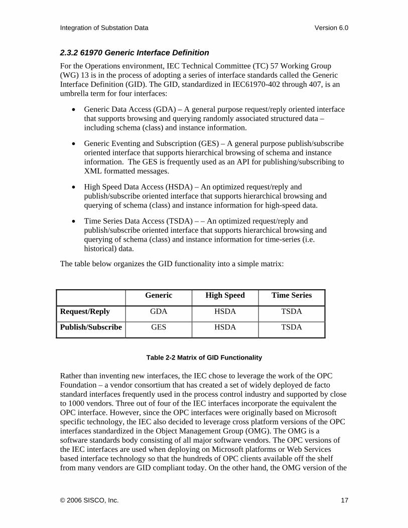
The table below organizes the GID functionality into a simple matrix:
Generic High Speed Time Series
Request/Reply GDA HSDA TSDA
Publish/Subscribe GES HSDA TSDA
Table 2-2 Matrix of GID Functionality Rather than inventing new interfaces, the IEC chose to leverage the work of the OPC Foundation – a vendor consortium that has created a set of widely deployed de facto standard interfaces frequently used in the process control industry and supported by close to 1000 vendors. Three out of four of the IEC interfaces incorporate the equivalent the OPC interface. However, since the OPC interfaces were originally based on Microsoft specific technology, the IEC also decided to leverage cross platform versions of the OPC interfaces standardized in the Object Management Group (OMG). The OMG is a software standards body consisting of all major software vendors. The OPC versions of the IEC interfaces are used when deploying on Microsoft platforms or Web Services based interface technology so that the hundreds of OPC clients available off the shelf from many vendors are GID compliant today. On the other hand, the OMG version of the
© 2006 SISCO, Inc. 17
Integration of Substation Data Version 6.0
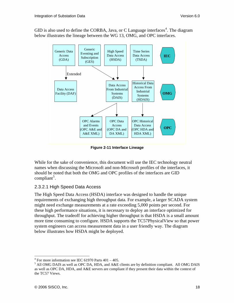
GID is also used to define the CORBA, Java, or C Language interfaces4. The diagram below illustrates the lineage between the WG 13, OMG, and OPC interfaces.
Generic Data Access(GDA)
High Speed Data Access
(HSDA)
Generic Eventing and Subscription
(GES)
Time Series Data Access
(TSDA)
OPC Historical Data Access
(OPC HDA and HDA XML)
OPC Alarms and Events
(OPC A&E and A&E XML)
OPC Data Access
(OPC DA and DA XML)
IEC
OPC
Historical Data Access From
Industrial Systems (HDAIS)
Data Access From Industrial
Systems (DAIS)
Data Access Facility (DAF) OMG
Extended
Figure 2-11 Interface Lineage
While for the sake of convenience, this document will use the IEC technology neutral names when discussing the Microsoft and non-Microsoft profiles of the interfaces, it should be noted that both the OMG and OPC profiles of the interfaces are GID compliant5.
2.3.2.1 High Speed Data Access The High Speed Data Access (HSDA) interface was designed to handle the unique requirements of exchanging high throughput data. For example, a larger SCADA system might need exchange measurements at a rate exceeding 5,000 points per second. For these high performance situations, it is necessary to deploy an interface optimized for throughput. The tradeoff for achieving higher throughput is that HSDA is a small amount more time consuming to configure. HSDA supports the TC57PhysicalView so that power system engineers can access measurement data in a user friendly way. The diagram below illustrates how HSDA might be deployed.
4 For more information see IEC 61970 Parts 401 – 405. 5 All OMG DAIS as well as OPC DA, HDA, and A&E clients are by definition compliant. All OMG DAIS as well as OPC DA, HDA, and A&E servers are compliant if they present their data within the context of the TC57 Views.
© 2006 SISCO, Inc. 18

Integration of Substation Data Version 6.0
SCADA
HSDA Server Interface
SCADA HMI
SCADA Data Client (such as an
archive or state estimator)
HSDA Client Interface HSDA Client Interface
Figure 2-12 Example of the Use of the High Speed Data Access Interface
2.3.2.2 Time Series Data Access The Time Series Data Access (TSDA) interface is designed for the exchange of arrays of data where each array contains the values of a single data point over time. The mechanics of efficiently passing these arrays requires a separate interface. TSDA supports the TC57 Views so that power system engineers can access time series data in a user friendly way.
Archive
TSDA Server Interface
Historical trending HMI
Time Series Data Client (such as an
thermal circuit analysis application)
TSDA Client Interface TSDA Client Interface
Figure 2-13 Example of the Use of the Time Series Data Access Interface
2.3.2.3 Generic Data Access The Generic Data Access (GDA) interface specification is the one standard interface that was not created from a previously existing OPC specification. GDA provides Read/Write access to data typically in a database. It is similar in functionality to ODBC but is
© 2006 SISCO, Inc. 19

Integration of Substation Data Version 6.0
platform and schema neutral6. The GDA leverages the work of NERC’s Security Coordinator’s Model Exchange Format (CIM XML) in how data is encoded for exchange. Using the GDA, a user accesses the data via the CIM terminology of classes, attributes, and relationships. As a result, it is an ideal way for vendors to expose their data in a CIM compliant way that is independent of a physical database schema as shown below:
Asset Data
GDA Server
Data Requester
GDA Client
61850Config
GDA Server
DNPConfig
GDA Server
Power System Model Data
GDA Server
Figure 2-14: GDA Supports Request/Reply
GDA includes the ability to notify clients when data has been updated in the server. This functionality provides an important piece of the puzzle when constructing an infrastructure that enables a single point of update for model changes. Using this function, the GDA client can be notified of changes in the underlying data automatically.
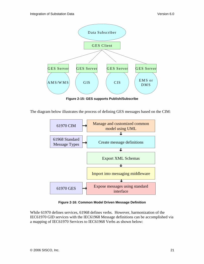
2.3.2.4 Generic Eventing and Subscription The Generic Eventing and Subscription (GES) interface provides an interface by which applications can publish and subscribe to CIM data. As a publish/subscribe oriented interface it supplies an ideal vendor-neutral interface for a generic application integration product such as those from the major IT vendors.
6 An ODBC interface is dependent on the structure and naming of rows and columns in relational tables. Unlike ODBC, the GDA interface is independent of how data may be physically stored in the database.
© 2006 SISCO, Inc. 20
Integration of Substation Data Version 6.0
A M S/W M S
G ES Server
D ata Subscriber
G ES C lient
G IS
G ES Server
C IS
G ES Server
EM S or D M S
G ES Server
Figure 2-15: GES supports Publish/Subscribe
The diagram below illustrates the process of defining GES messages based on the CIM:
Manage and customized common model using UML
Create message definitions
Export XML Schemas
Import into messaging middleware
61968 Standard Message Types
61970 CIM
Expose messages using standard interface
61970 GES
Figure 2-16: Common Model Driven Message Definition
While 61970 defines services, 61968 defines verbs. However, harmonization of the IEC61970 GID services with the IEC61968 Message definitions can be accomplished via a mapping of IEC61970 Services to IEC61968 Verbs as shown below:
© 2006 SISCO, Inc. 21

Integration of Substation Data Version 6.0
WG 14 Verbs GID Service Used
Create GDA Update: create_resourceChange GDA Update: set_values/TSDA/HSDA writeCancel GDA Update: set_valuesClose GDA Update: set_valuesDelete CDA Update: delete_resourceGet GDA Filtered Query/TSDA/HSDA readCreated GDA Event/published GES message
Changed GDA Event/published GES message
Closed GDA Event/published GES message
Canceled GDA Event/published GES message
Show Publication of an GES MessageReply GDA Exception/publication of a GES messageSubscribe GES/HSDA Subscription Unsubscribe GES/HSDA Subscription
Table 2-3: Mapping from IEC61968 Verbs to IEC61970 Services
Using the mapping described above, the 61970 services can be used to exchange 61968 messages.
2.3.2.5 Model Aware Interfaces and Views The mechanism used to exchange data is determined by an application’s interface. However, the native interface provided by an application is often limited. For example, legacy interfaces typically do not provide a means to discover what instance data is processed by a particular component at run time other than a rudimentary listing of legacy IDs. Furthermore, legacy data cannot typically be viewed within the context of an inter-application data model such as a view of a CIM.
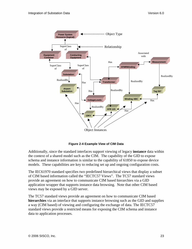
In order to fully enable a complete information model, an interface needs to specify two related mechanisms. The first specifies a programmatic interface that a component or component wrapper must implement. The second specifies how an information model such as the CIM or 61850 is exposed via the programmatic interface. The later concept is embodied in the term “view”. A view not only includes type information, but also typically includes instance information as shown below:
© 2006 SISCO, Inc. 22
Integration of Substation Data Version 6.0
XFMRWinding
Substation
Transformer
VoltageLevels
Measurement
Has
SuperClassof
Has
Has
Associated with
Power System Resource (logical)
SuperClassof
Equipment Container
Conducting Equipment
SuperClassof
Relationship
Object Type
Airport Substation
13KV
HasRealizedBy
RealizedBy
Object Instances
XFR 123 Has
Has
RealizedBy
Winding ABC
Tag 567
RealizedBy
RealizedBy
Figure 2-4 Example View of CIM Data
Additionally, since the standard interfaces support viewing of legacy instance data within the context of a shared model such as the CIM. The capability of the GID to expose schema and instance information is similar to the capability of 61850 to expose device models. These capabilities are key to reducing set up and ongoing configuration costs.
The IEC61970 standard specifies two predefined hierarchical views that display a subset of CIM based information called the “IECTC57 Views”. The TC57 standard views provide an agreement on how to communicate CIM based hierarchies via a GID application wrapper that supports instance data browsing. Note that other CIM based views may be exposed by a GID server.
The TC57 standard views provide an agreement on how to communicate CIM based hierarchies via an interface that supports instance browsing such as the GID and supplies a way (CIM based) of viewing and configuring the exchange of data. The IECTC57 standard views provide a restricted means for exposing the CIM schema and instance data to application processes.
© 2006 SISCO, Inc. 23

Integration of Substation Data Version 6.0
Two hierarchical views are standardized in IEC61970. They are:
• TC57PhysicalView
• TC57EventingView
The TC57PhysicalView hierarchy is a tree that orders power system related instance data in accordance to how it is contained from a physical perspective. Companies contain sub control areas; sub control areas contain substations, etc. The idea is that a power system engineer can find a breaker without having to remember a potentially convoluted or inconsistent naming scheme as shown below.
TC57PhysicalView
ProgressiveElectric
North Sub Control Area
Airport
Breaker 12
Transformer 22
IndustrialBlvd Substation
Breaker 13
Transformer 23
Figure 2-5 Example TC57PhysicalView
The TC57EventingView hierarchy is associated with the Generic Eventing and Subscription (GES) interface, the standard interface for publishing and subscribing described below. The tree allows an application to describe what message types (application data schema) it publishes as well as the content of each message type.
© 2006 SISCO, Inc. 24

Integration of Substation Data Version 6.0
Change of Service Report
Procedure Code
Device Location
TC57EventingViewCustomer Information System
New Customer Event
Customer AddressDate of Service
CustomerEffective DateOld Service
Maintenance Management SystemNew Work Order
Device Type
Breaker Test ReportBreaker IDTest Date
Work Order Number
Customer Number
Figure 2-69 Example TC57EventingView
2.3.2.5.1 The use of views This section describes how a view can be used at an application interface to make utility data more understandable and usable. For example consider the diagram below:
Customer Data ConsumerFlat set of records
CIS
Record 1
Record 2
Record 3
Record 4
Record 5
Record6
Figure 2-20 Traditional view of utility data
Figure 2- shows how data is often presented by a typical legacy application. In this case, customer data is presented to an application as a flat set of records without much information about how customers relate to information modeled in the CIM such as network topology or maintenance history. However, if one is interested in correlating the
© 2006 SISCO, Inc. 25
Integration of Substation Data Version 6.0
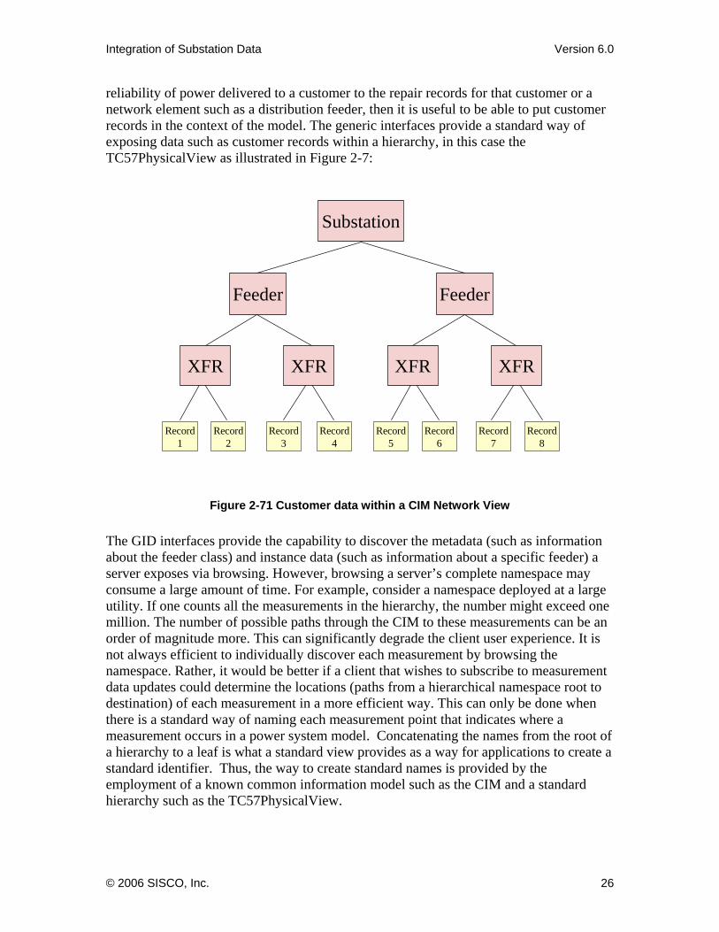
reliability of power delivered to a customer to the repair records for that customer or a network element such as a distribution feeder, then it is useful to be able to put customer records in the context of the model. The generic interfaces provide a standard way of exposing data such as customer records within a hierarchy, in this case the TC57PhysicalView as illustrated in Figure 2-7:
Feeder
Substation
XFR XFR
Feeder
XFR XFR
Record 1
Record 2
Record 3
Record 4
Record 5
Record 6
Record 7
Record 8
Figure 2-71 Customer data within a CIM Network View
The GID interfaces provide the capability to discover the metadata (such as information about the feeder class) and instance data (such as information about a specific feeder) a server exposes via browsing. However, browsing a server’s complete namespace may consume a large amount of time. For example, consider a namespace deployed at a large utility. If one counts all the measurements in the hierarchy, the number might exceed one million. The number of possible paths through the CIM to these measurements can be an order of magnitude more. This can significantly degrade the client user experience. It is not always efficient to individually discover each measurement by browsing the namespace. Rather, it would be better if a client that wishes to subscribe to measurement data updates could determine the locations (paths from a hierarchical namespace root to destination) of each measurement in a more efficient way. This can only be done when there is a standard way of naming each measurement point that indicates where a measurement occurs in a power system model. Concatenating the names from the root of a hierarchy to a leaf is what a standard view provides as a way for applications to create a standard identifier. Thus, the way to create standard names is provided by the employment of a known common information model such as the CIM and a standard hierarchy such as the TC57PhysicalView.
© 2006 SISCO, Inc. 26

Integration of Substation Data Version 6.0
In addition to just providing a way for applications to publish or subscribe to measurements, the GES interface can use TC57 Views to provide access to non measurement CIM data. GES provides a power system oriented mechanism for generic data subscription configuration that power system engineers can use. The diagram below illustrates a sample TC57PhysicalView. The namespace would typically be displayed in a subscription configuration graphical user interface (GUI). By displaying a view of the power system model in a message subscription configuration GUI, the user can set up message subscriptions without having to know the subscription configuration script syntax used by a generic application integration tool.
North Area
Airport Substation
Main Substation
Breakers Loads Breakers TransformersTransformers
Company X
TC57PhysicalView
Figure 2-82 TC57PhysicalView Used As A Subscription Topic Tree
Using the example namespace above, the user could subscribe to purchase orders or work orders, for example, related to a company, to just a particular substation, or just a set of devices in a substation – potentially all done via a user friendly GUI.
2.3.2.6 GID Benefits The GID provides the following key functionality required to lower integration costs and increase visibility of substation data:
• The interfaces can be implemented over a variety of communication profiles such as a message bus or database technology. This means a single application wrapper can be used regardless on the technology used to perform integration.
• As application independent, the same interfaces are used to wrap any application. This means that new wrappers do not need to be developed every time an application is added to the system. This creates a consistent and easy to use
© 2006 SISCO, Inc. 27

Integration of Substation Data Version 6.0
integration framework by providing a unified programming model for application integration.
• Interfaces support schema announcement/discovery – Device and application schemas are discoverable so that component configuration can be done programmatically at run time. Programmatically exposing the schema of application data can eliminate a great deal of manual configuration. Furthermore, the interfaces support presenting business objects within CIM based views – Each component describes the substation object instances that it supports within a view of CIM data. It is not enough to merely expose the application data schema, one must also expose what specific breakers, transformers, etc., that an application operates on. This also eliminates manual configuration as well as provides a means for a power system engineer to understand how substation data is organized and accessed (similar to the device modeling description capabilities of 61850).
• Model based Views - Viewing instance data in a CIM context helps eliminate manual configuration and provides a means for a power system engineer to understand how enterprise data is organized and accessed. This makes data more understandable and “empowers the desktop” by enabling power system engineers to accomplish many common configuration tasks instead of having to rely on IT personnel.
• Enhances interoperability by “going the last mile”. Agreement on the “what” of data is not enough to ensure component interoperability. We also need to standardize on “how” data is accessed. To provide a simple analogy, the U.S.A. standardized on a 110/220 volt 60 hertz sine wave for residential electrical systems. This is the standardization of “what”. However, we also standardized the design of the plugs and receptacles. This is the standardization of the “how”. The standardization of plugs and receptacles means that we don’t need to call an electrician every time we want to install a toaster. Similarly with software, standardizing on the interface means a connector does not need to be created from scratch every time we install a new application.
• Since application vendors can “shrink wrap” a CIM/GID compliant wrapper, the use of the CIM and GID can lower the cost of integration to utilities by fostering the market for off-the-shelf connectors supplied by application vendors or 3rd parties. The time and money associated with integration wrapper development and maintenance is very high. Typically, wrapper development is the largest component of cost for application integration. An off-the-shelf CIM/GID wrapper can replace custom-built wrappers that are built again and again for each new system. The availability of off-the-shelf CIM/GID compliant wrappers is a key to lowering application integration and substation analysis application deployment and maintenance costs very significantly.
© 2006 SISCO, Inc. 28
Integration of Substation Data Version 6.0
2.4 Integration Solutions With regard to substation and operations environment integration, the following section discusses the integration of the CIM and IEC61850 and how services can be used to provide choices with regard to the use of gateways.
The gateway based solution described at the end of section 2.2.1, goes a long way toward supporting the interoperability of telemetry data servers with telemetry data clients. In this case, the DNP protocol is replaced by 61850 when communicating with asset management applications running in the substation or control center. In this way, 61850 and DNP3 devices and networks can be aggregated into a single integrated whole.
However, at times one would like to expose substation data within the context of a combined 61850/61970/61968 model. How can this be done using 61850 since 61850 can not be used to expose all of CIM data?
The figure below shows the mapping of four analog measurements (voltage, active power, current and reactive power) available in two protection IED’s that support the DNP3 protocol into a combined CIM/61850 based rich model. These measurements are represented in DNP3 as 4 data points. Each of them has to be mapped into the hierarchical rich model defined in CIM and 61850.
In the CIM model, a PowerSystemResource (PSR) may have zero to many measurements associated with it. Each measurement may contain one or more measurement values. Measurements of a PSR are classified by MeasurementType.
The MeasurementType.name in the CIM model is the IEC IEC61970 name assigned, while the MeasurementType.aliasName is the name assigned to the type in IEC IEC61850. For example Volts in the figure below is the MeasurementType.aliasName for the Voltage MeasurementType.name.
© 2006 SISCO, Inc. 29

Integration of Substation Data Version 6.0
DNP Device A
DNP Device B
Example DNP Namespace
Point 1
Point 2
Point 3
Point 1
Point 2
Point 3
North Area
Airport Substation
Map individual
DNP point to elements in a rich model
Example 61850/CIM Namespace
Relay 1
MeasurementsMMXU1
A PhV
phsA
Cval
mg
f[MX]
phsA
Cval
mg
f[MX]
phsA
Cval
mg
f[MX]
phsA
Cval
mg
f[MX]
phsA
Cval
mg
f[MX]
phsA
Cval
mg
f[MX]
From 61970
From 61850
Figure 2-23 Mapping a DNP3 points into a harmonized
IEC61850/61970/61968 View
Once this mapping of DNP3 data items into the 61850/61970/61968 view is accomplished, then can use the GID to exposing this rich view7.
Using the GID provides a solution that does not necessarily require a 61850 gateway. Using the GID, the fact that DNP3 or IEC61850 are used for the field communications can be completely hidden from the client by the GID interface without having to wrap the DNP3 protocol with the 61850 protocol. From the client’s point of view, there is only a single GID telemetry server that presents a rich 61850/CIM name space. Adoption of standard ways of representing what data is exchanged combined with standards ways for how data is exchanged allow us to fully integrate SCADA systems and use the SCADA protocol most appropriate for the environment with, without or in combination with a 61850 gateway.
In the diagram below, a 61850/CIM View provided by a GID server is used to expose DNP3 data . The GID interface presents a 61850/CIM View of substation devices without requiring the 61850 wire protocol implemented in a DNP3 to 61850 gateway. A new GID Client for EMS operations applications, as well as a second GID Client for network analysis applications are being integrated with the DNP3 and IEC 61850 field 7 Note that the mapping of control functions on to the GID has not been taken up by IEC TC 57 yet.
© 2006 SISCO, Inc. 30
Integration of Substation Data Version 6.0
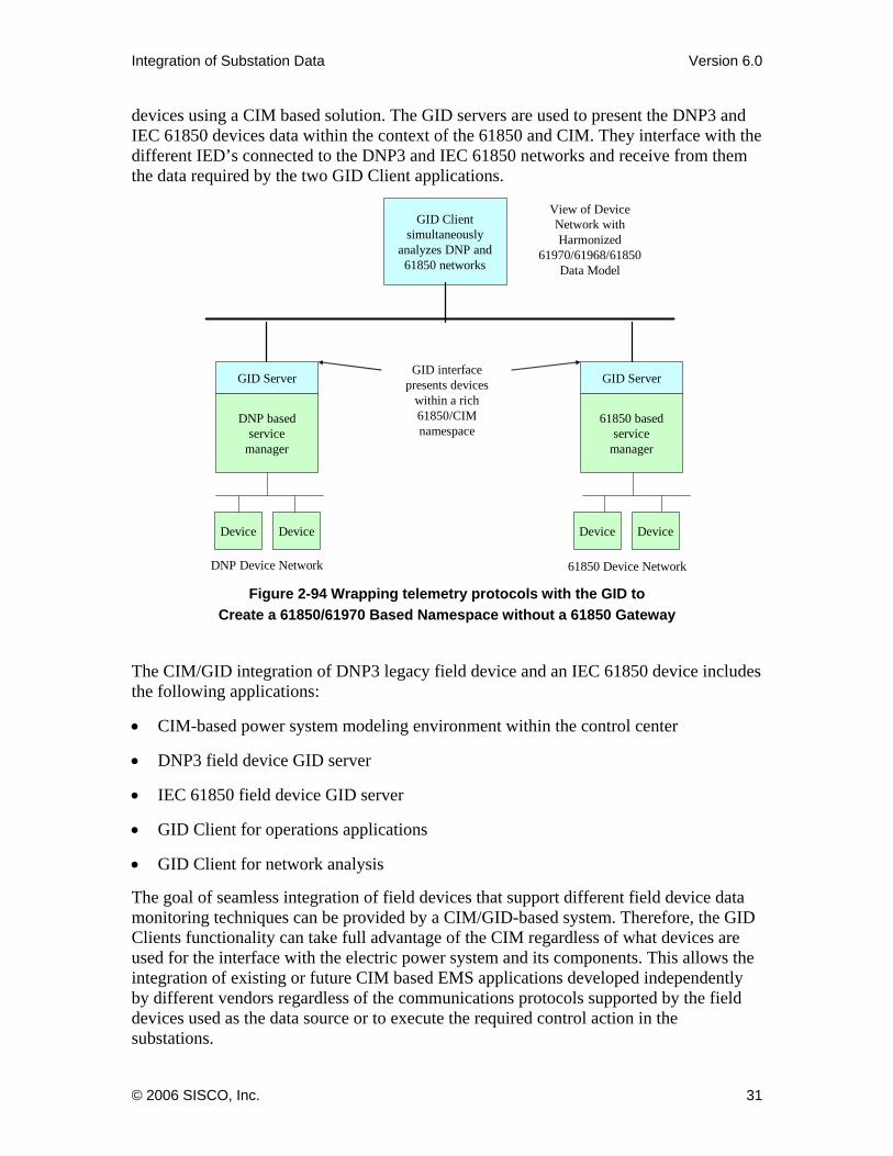
devices using a CIM based solution. The GID servers are used to present the DNP3 and IEC 61850 devices data within the context of the 61850 and CIM. They interface with the different IED’s connected to the DNP3 and IEC 61850 networks and receive from them the data required by the two GID Client applications.
61850 Device Network
DNP basedservice
manager
61850 basedservice
manager
View of Device Network with Harmonized
61970/61968/61850 Data Model
GID interface presents devices
within a rich 61850/CIM namespace
GID Server GID Server
GID Client simultaneously
analyzes DNP and 61850 networks
Device Device Device Device
DNP Device Network
Figure 2-94 Wrapping telemetry protocols with the GID to Create a 61850/61970 Based Namespace without a 61850 Gateway
The CIM/GID integration of DNP3 legacy field device and an IEC 61850 device includes the following applications:
• CIM-based power system modeling environment within the control center
• DNP3 field device GID server
• IEC 61850 field device GID server
• GID Client for operations applications
• GID Client for network analysis
The goal of seamless integration of field devices that support different field device data monitoring techniques can be provided by a CIM/GID-based system. Therefore, the GID Clients functionality can take full advantage of the CIM regardless of what devices are used for the interface with the electric power system and its components. This allows the integration of existing or future CIM based EMS applications developed independently by different vendors regardless of the communications protocols supported by the field devices used as the data source or to execute the required control action in the substations.
© 2006 SISCO, Inc. 31
Integration of Substation Data Version 6.0
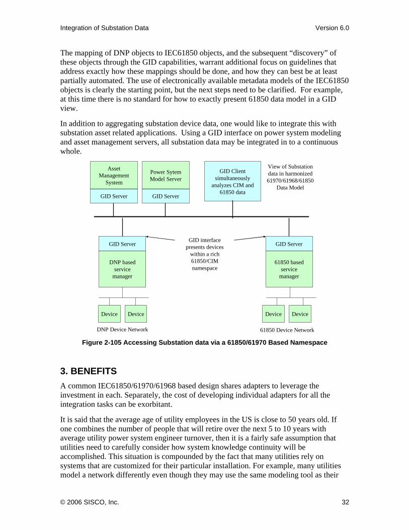
The mapping of DNP objects to IEC61850 objects, and the subsequent “discovery” of these objects through the GID capabilities, warrant additional focus on guidelines that address exactly how these mappings should be done, and how they can best be at least partially automated. The use of electronically available metadata models of the IEC61850 objects is clearly the starting point, but the next steps need to be clarified. For example, at this time there is no standard for how to exactly present 61850 data model in a GID view.
In addition to aggregating substation device data, one would like to integrate this with substation asset related applications. Using a GID interface on power system modeling and asset management servers, all substation data may be integrated in to a continuous whole.
61850 Device Network
DNP basedservice
manager
61850 basedservice
manager
View of Substation data in harmonized 61970/61968/61850
Data Model
GID interface presents devices
within a rich 61850/CIM namespace
GID Server GID Server
GID Client simultaneously
analyzes CIM and 61850 data
Device Device Device Device
DNP Device Network
GID Server
Asset Management
System
GID Server
Power SytemModel Server
Figure 2-105 Accessing Substation data via a 61850/61970 Based Namespace
3. BENEFITS A common IEC61850/61970/61968 based design shares adapters to leverage the investment in each. Separately, the cost of developing individual adapters for all the integration tasks can be exorbitant.
It is said that the average age of utility employees in the US is close to 50 years old. If one combines the number of people that will retire over the next 5 to 10 years with average utility power system engineer turnover, then it is a fairly safe assumption that utilities need to carefully consider how system knowledge continuity will be accomplished. This situation is compounded by the fact that many utilities rely on systems that are customized for their particular installation. For example, many utilities model a network differently even though they may use the same modeling tool as their
© 2006 SISCO, Inc. 32
Integration of Substation Data Version 6.0
neighbor. A solution to this problem can include agreement by utilities on standardized best practices. Not only will agreement between utilities enlarge the knowledge pool so that more effective integration and analysis can be accomplished, it will allow utilities to wean themselves off customized solutions. The IEC standards can play an important role in the move towards non-biased standardized solutions. The architecture presented here is entirely based on standardized interfaces – free of political tugs-of-war and vendor lock-in. Adoption of this architecture can help provide the continuity that utilities need.
As stated above, the cost of application adapters required to for an infrastructure for integration and analysis is the most significant cost of deploying these technologies. An integration infrastructure based on the architecture described here helps enable the availability of off-the-shelf wrappers because application vendors and 3rd parties can now reasonably expect that a solution developed for one location could be used in others too. Furthermore these wrappers can be deployed independently of what integration infrastructure the utility happens to choose.
Standardization of the IEC technologies fosters interoperability of components for many uses. One market that will likely be created as a result of this standardization is the market for IEC61850/61970/61968 based analysis applications or application add-ons. Today, every analysis applications or application add-on must be extensively customized for every deployment. If an analysis or add-on application supplier can assume the existence of the IEC standards, then the supplier can sell the same tool to different utilities with a minimal amount of customization. Decreased development cost, together with competition, should help drive down prices.
As discussed previously, traditional integration techniques are limited by not providing the capability to discover information. The approach proposed in this report facilitates inclusion of unstructured data and avoids preordaining how data will be organized and analyzed. In doing so, this approach provides a flexible approach for the future.
Fundamentally, integration using the architecture described above involves looking at the big picture. However, integration may encompass data from a large or small set of applications. One does not need to undertake a major project that requires many months to complete. The issue here is the development of a long-term enterprise wide integration strategy so that a small integration project does not become just another slightly larger island of automation. Thinking at the enterprise level while integrating at the department level minimizes risk and maximizes the chances for long-term success. Within the context of a long-term plan, this architecture makes it possible to tackle the problem of integration in a staged approach. Rather than having to understand the relative mapping of the entire shared model for each application that you may need in the future, the approach lets you start with a more focused approach and expand the solution over time. For example, the GID can be used to provide a CIM wrapper on existing applications. You could start with one existing application to enable the standards based integration of only that specific database. You can then increase the scope of the incrementally until, eventually, all data in the various databases and applications are all available via a unified IEC61850/61970 view. The inevitable inconsistencies in meaning or content between existing databases and applications can be gradually discovered and eliminated as
© 2006 SISCO, Inc. 33

Integration of Substation Data Version 6.0
needed. In this manner, the IEC61850/61970 approach delivers incremental value with staged effort throughout the process.
The sections above have described how the use of a standards based architecture can allow components to connect and exchange information automatically. However, there is one problem that cannot be resolved via standards. The remaining problem is that every utility typically names objects such as a breaker, substation, or any other resource in a non-uniform manner. The ID used to refer to an individual breaker in one application will frequently not match the name in a second application. To get the two applications to exchange data, a name mapping must be created. This remains a persistent road block to complete “plug and play”. However, creating a name mapping table does not require custom programming and can frequently be partially automated by using the name conventions that do exist within most applications.
The benefits of standardized data models and component interfaces are clear. Utilities can significantly lower the cost of performing integration by leveraging off-the-shelf components and wrappers from application vendors or third parties. Furthermore, the standard models and the standard interfaces provide a power system specific mechanism to more easily deploy, configure and use an integration infrastructure. As a result, a utility can achieve greater efficiencies and adaptability at a cost that is not prohibitive.
© 2006 SISCO, Inc. 34