
INTEGRATION OF PRE-SIMULATION AND SENSORLESS MONITORING FOR SMART MOULD...
14
Int j simul model 15 (2016) 4, 623-636 ISSN 1726-4529 Original scientific paper DOI:10.2507/IJSIMM15(4)4.354 623 INTEGRATION OF PRE-SIMULATION AND SENSORLESS MONITORING FOR SMART MOULD MACHINING Kim, S.-J. Department of Mechanical Engineering, Gyeongsang National University, Jinju 52818, Republic of Korea E-Mail: [email protected] Abstract A smart mould machining system, which detects machining status and controls the CNC through pre- simulation and real-time data, was developed. Pre-simulation predicts cutting forces, and inserts the best feed rate and virtual load on each line of the NC data. The active feed rate reduced machining by up to 36 %, without increasing the maximum cutting forces. The actual cutting load was computed from spindle load data and a friction load compensation algorithm. Collision and tool wear were detected by comparing the actual and virtual load, with the time synchronised by using tool position data. The system machined an automotive grill mould cavity for 34 hours without the supervision of a worker, because pre-simulation had stabilized the milling process and monitoring would have stopped the process if the actual load was different to the virtual load. Pre-simulation has been verified by thousands of mould makers and integrated with sensorless monitoring in an open CNC. (Received in November 2015, accepted in April 2016. This paper was with the author 1 month for 1 revision.) Key Words: Smart Mould Machining, Pre-Simulation, Feed Rate Control, Sensorless Monitoring, Tool Wear, Open CNC 1. INTRODUCTION A mould is a special shaped cavity used to produce large quantities of the same product. A plastic part is designed by CAD and modified by the numerical simulation of injection moulding process. A mould-base type is selected and final cavity and core are designed [1]. Manufacturing companies develop a mould and produce millions of parts from it using a plastic injection machine. Mass production lines repeat the machining of lots of the same parts through a single NC program, but mould machining is always the first process when using a new workpiece, cutting tools or NC program for each design. New NC data for complex moulds, which are prone to collision accidents, tool wear and tool breakages, have their cutting conditions set based on the worst case geometry. Though the machine tool stops if the feed driving or spindle motor load is larger than the fixed maximum value, this may occur after all the teeth of the tool have already been broken or a collision between the spindle and workpiece has happened. The operator has to monitor the NC machine during the operation and push the stop button in cases of abnormal cutting states, even though it is a fully automated machine tool. The first system required in the mould industry is practical machining process monitoring. This allows the machine to be observed without an operator after the stock is fixed on the table and cutting tools are prepared in the tool changer magazine. A significant amount of research has been dedicated to the task of cutting tool monitoring [2]. A direct measurement of tool wear on machine tools using laser displacement sensor is presented [3]. A frequent approach used in laboratories is to attach vibration, acoustic emission and dynamometer sensors to the machine and then monitor the signals obtained. The measurement of cutting force is commonly taken using a table-mounted dynamometer, which is an essential tool for laboratory based experimental work [4-6]. Flank wear and tooth breakage can be monitored from acceleration and vibration signals during milling [7, 8]. The practical approach applied in machine shops is to monitor spindle or feed drive current without using expensive additional sensors. The cutting forces in the x, y and z axes, which
Transcript of INTEGRATION OF PRE-SIMULATION AND SENSORLESS MONITORING FOR SMART MOULD...

Int j simul model 15 (2016) 4, 623-636
ISSN 1726-4529 Original scientific paper
DOI:10.2507/IJSIMM15(4)4.354 623
INTEGRATION OF PRE-SIMULATION AND SENSORLESS
MONITORING FOR SMART MOULD MACHINING
Kim, S.-J.
Department of Mechanical Engineering, Gyeongsang National University, Jinju 52818,
Republic of Korea
E-Mail: [email protected]
Abstract
A smart mould machining system, which detects machining status and controls the CNC through pre-
simulation and real-time data, was developed. Pre-simulation predicts cutting forces, and inserts the
best feed rate and virtual load on each line of the NC data. The active feed rate reduced machining by
up to 36 %, without increasing the maximum cutting forces. The actual cutting load was computed
from spindle load data and a friction load compensation algorithm. Collision and tool wear were
detected by comparing the actual and virtual load, with the time synchronised by using tool position
data. The system machined an automotive grill mould cavity for 34 hours without the supervision of a
worker, because pre-simulation had stabilized the milling process and monitoring would have stopped
the process if the actual load was different to the virtual load. Pre-simulation has been verified by
thousands of mould makers and integrated with sensorless monitoring in an open CNC. (Received in November 2015, accepted in April 2016. This paper was with the author 1 month for 1 revision.)
Key Words: Smart Mould Machining, Pre-Simulation, Feed Rate Control, Sensorless Monitoring,
Tool Wear, Open CNC
1. INTRODUCTION
A mould is a special shaped cavity used to produce large quantities of the same product. A
plastic part is designed by CAD and modified by the numerical simulation of injection
moulding process. A mould-base type is selected and final cavity and core are designed [1].
Manufacturing companies develop a mould and produce millions of parts from it using a
plastic injection machine. Mass production lines repeat the machining of lots of the same
parts through a single NC program, but mould machining is always the first process when
using a new workpiece, cutting tools or NC program for each design. New NC data for
complex moulds, which are prone to collision accidents, tool wear and tool breakages, have
their cutting conditions set based on the worst case geometry. Though the machine tool stops
if the feed driving or spindle motor load is larger than the fixed maximum value, this may
occur after all the teeth of the tool have already been broken or a collision between the spindle
and workpiece has happened. The operator has to monitor the NC machine during the
operation and push the stop button in cases of abnormal cutting states, even though it is a fully
automated machine tool. The first system required in the mould industry is practical
machining process monitoring. This allows the machine to be observed without an operator
after the stock is fixed on the table and cutting tools are prepared in the tool changer magazine.
A significant amount of research has been dedicated to the task of cutting tool monitoring
[2]. A direct measurement of tool wear on machine tools using laser displacement sensor is
presented [3]. A frequent approach used in laboratories is to attach vibration, acoustic
emission and dynamometer sensors to the machine and then monitor the signals obtained. The
measurement of cutting force is commonly taken using a table-mounted dynamometer, which
is an essential tool for laboratory based experimental work [4-6]. Flank wear and tooth
breakage can be monitored from acceleration and vibration signals during milling [7, 8]. The
practical approach applied in machine shops is to monitor spindle or feed drive current
without using expensive additional sensors. The cutting forces in the x, y and z axes, which

Kim: Integration of Pre-Simulation and Sensorless Monitoring for Smart Mould Machining
624
were measured indirectly from the current of the feed-drive servo motors, were used for
cutting force regulation and tool monitoring in slow face milling [9-12]. The monitoring of
spindle load or current is a well-established approach to tool condition monitoring using
adaptive control [11-14]. Spindle current monitoring was utilized to develop an adaptive
control for machine tools when workpiece geometry is unknown [13-15]. A time series
autoregressive model proposed a method for monitoring tool breakage [16].
The previous adaptive control or time series autoregressive model is useful for drilling or
simple milling processes in mass production, where the same machining pattern is repeated.
However, it is insufficient when it comes to new NC data of complex mould geometries and
changing cutting conditions. Therefore, a robust monitoring model, which separates the
measured load of an abnormal cutting state from the general load change induced by an
increase in cut depth or changes in cutting conditions, needs to be applied in mould machining,
where the cutting geometry and conditions change often during the process.
In this paper, a smart mould machining system, which recognises cutting status and
adjusts to better cutting conditions using pre-simulation data and real-time measured signals,
has been developed. Pre-simulation estimates machining loads by assuming an ideal tool, and
inserts the best feed rates and virtual loads on every line of output NC data. Real-time
monitoring recognises collision and tool wear by comparing actual and virtual load data.
The reference virtual load is estimated by pre-simulation of NC machining developed
using Visual C++ and the OpenGL library. Instantaneous cutting forces and average powers
are computed from the specific cutting energy and intersection of tool and workpiece [17-24].
The active feed rate is inserted in NC data to reduce machining time while the instantaneous
maximum cutting force is below the limit. Instantaneous cutting forces are compared with
forces measured by the tool dynamometer, and virtual cutting load is compared with the
actual load gathered from spindle load data. The developed smart mould machining system
has been verified by mould makers, and integrated in an open CNC easily because pre-
simulation and sensorless monitoring software does not require additional sensors or
instruments.
2. PRE-SIMULATION
2.1 Machining simulation and collision avoidance
The simulation system reads the NC data generated by commercial CAM software. It
recognizes the diameter and corner radius of the tool from NC code comments and inputs the
starting workpiece geometry. The stock model is expressed by z-buffer, which is useful for 3-
axis cutting simulations [17, 18]. Pre-simulation verifies the NC data and protects machine
tools from collisions between spindle heads, holders, fixtures, workpieces and cutting tools.
The safe and shortest tool-setting algorithm using a safe space was proposed and applied in
NC machining [19]. The safe space is the volume in a tool coordinate system that does not
interfere with the workpiece, and the holder located in the safe space never collides with the
workpiece. Collisions at rapid motion between the safe space and workpiece are demonstrated
in pre-simulation. If a rapid motion collision is predicted, the rapid motion height is increased
to a safe height. If the original rapid height is too high, resulting in a loss of rapid motion time,
the height is decreased to the lowest safe height. The tool holder assembled in the safe space
does not collide with the workpiece.
2.2 Cutting force model and experiment
Cutting force is computed using chip geometry, which is the overlap of the workpiece and
tool moving along tool paths [20]. Pre-simulation calculates the instantaneous cutting forces
using chip removal geometries. Chip removal geometries are divided into small pieces on a

Kim: Integration of Pre-Simulation and Sensorless Monitoring for Smart Mould Machining
625
cylindrical coordinate to estimate element cutting forces more accurately, as shown in Fig. 1.
The uncut chip thickness tc, i.e., the thickness of the material removed by a flute, at any
location on the cutter, can be determined using Eq. (1), where ft is the feed per tooth vector
and ns is the unit normal vector of cutter surface at the angular position θ and axial height z
[21, 22].
𝑡𝑐(𝜃, 𝑧) = 𝑓𝑡 ∙ 𝑛𝑠(𝜃, 𝑧) (1)
Figure 1: Element cutting forces on a tool.
The element cutting forces on a tooth are computed from the chip area and specific cutting
energy, which also changes with the uncut chip thickness. The relationship between a specific
cutting energy and uncut chip thickness, as proposed by Sabberwal, is used to consider the
size effect [21-26]. The specific cutting energy is a function of the uncut chip thickness and
empirical constants Kc and p, which are dependent on the tool and material. The tangential
and radial components of the element cutting forces dFc are computed from the specific
cutting energy, chip thickness and chip width dz, as shown in Eq. (2).
[𝑑𝐹𝑐𝑇𝑑𝐹𝑐𝑅
] = [𝐾𝑐𝑇(𝑡𝑐)
𝑝𝑇
𝐾𝑐𝑅(𝑡𝑐)𝑝𝑅] 𝑑𝑧 (2)
Fig. 1 shows the element cutting forces when a tool moves in a direction that is -40
degrees downward or horizontal or +40 degrees upward. The instantaneous cutting force Fc is
computed by adding the element cutting forces of tooth N along the axial depth of the cut da,
as shown in Eq. (3) [21-25].
[𝐹𝑐𝑋(𝜃)
𝐹𝑐𝑌(𝜃)] = ∫ ∑ [
cos(𝜃) −sin(𝜃)
sin(𝜃) cos(𝜃)] [𝐾𝑐𝑇(𝑡𝑐)
𝑝𝑇
𝐾𝑐𝑅(𝑡𝑐)𝑝𝑅]𝑛
1 𝑑𝑧𝑑𝑎𝑑0
(3)
The instantaneous cutting force computation model was verified by comparing with
experimental forces measured using a table-mounted tool dynamometer. The cutting tool is a
10-mm-diameter ball end mill and the workpiece is SM45C carbon steel. The spindle speed is
1000 rpm and feed rate is 200 mm/min. Fig. 2 (top) shows the predicted instantaneous cutting
forces, and Fig. 2 (bottom) shows the actual instantaneous cutting force measured by the tool
dynamometer when the axial cut depth is 5mm and radial cut depth is changed from 5 mm to
1 mm. The predicted cutting force is similar to the experimental one.
2.3 Feed rate pre-control to reduce machining time
A cutting tool is deflected and vibrated by the maximum instantaneous cutting force. Pre-
simulation controls the feed rate, shortening the machining time, while the maximum forces

Kim: Integration of Pre-Simulation and Sensorless Monitoring for Smart Mould Machining
626
are below the limits [21]. This was evaluated by cutting a 50 mm 50 mm 50 mm piece of
SM45C carbon steel with a 10-mm-diameter flat end mill. The machining time is 3 min 40 s
when using the original NC data with a constant feed rate. The machining time is 2 min 20 s
when the optimized NC data with a controlled feed rate is used. Machining time savings of
approximately 36 % are achieved by using the pre-controlled feed rate, while the maximum
cutting force is not increased, as shown in Fig. 3.
Figure 2: Predicted (top) and measured (bottom) instantaneous cutting forces.
Figure 3: Pre-control feed rate to save machining time.
Controlling feed rate based on chip geometry can achieve process stability when milling
complex moulds [25]. The machining conditions of NC data, generated by CAD software are
single, although the cutting depth and direction change at each line of the tool path. The
simulation system knows the chip geometry of every rotation angle of the teeth. It regulates
cutting conditions by using the cutting force required to remove the chip geometry, as well as
the database, which takes into account the cutting tools, workpiece materials and machine tool

Kim: Integration of Pre-Simulation and Sensorless Monitoring for Smart Mould Machining
627
specifications, as shown in Fig. 4. The regulated feed rate in NC data allows for safe and fast
machining. The pre-simulation system was developed through 10-year collaboration between
the author and a company using C++ language and the OpenGL library. It was
commercialized successfully and thousands of mould makers are using it to pre-control
cutting conditions before real machining [27]. The virtual load computation algorithm and
sensorless monitoring system were developed for this research and integrated with the pre-
simulation in an open CNC.
Figure 4: Pre-simulation software.
2.4 Virtual load for monitoring
A virtual load calculation function was developed for this research and used at the sensorless
monitoring step. The pre-simulation virtual load is the power required to cut the workpiece
under various mould machining conditions. It does not include the power required to rotate
the spindle against static friction or to accelerate spindle speed.
The cutting power Pc is computed by adding all element torques computed using the
specific cutting energy and chip volume, as shown in Eq. (4). The experimental constants KcT
and pT of the specific cutting energy change with tool wear. They are independent of the
cutting depth and machining conditions, which are computed by simulation. Robust
monitoring, which divides the tool wear and chip removal volume, is possible, if simulation
and monitoring are integrated into a system.
𝑃𝑐 = ∫ ∫ ∑ 𝐾𝑐𝑇(𝑡𝑐)𝑝𝑇𝑛
1 𝑑𝑧𝑑𝑎𝑑0
𝑟𝜔𝑑𝜃2𝜋
0 (4)
The spindle load data of the controller represent the relative units computed by dividing
the current spindle power by the maximum power of the machine. The virtual cutting load PV
is computed by changing the unit of cutting power with an empirical constant CV, which is
dependent on the machine tool, as shown in Eq. (5).
𝑃𝑉 = 𝐶𝑉𝑃𝑐 (5)
The pre-simulation system inputs the workpiece size, roughing tool and tool path. It
simulates machining and outputs the machined stock and NC data including pre-control
cutting conditions and virtual cutting load information. The stock generated from the previous
simulation is input into the next step. The estimated virtual load is expressed by the special
code “(L number)” inserted at the end of every NC code block. The tool position and virtual
load data of each line are the references for the sensorless monitoring step.
3. SENSORLESS MONITORING
3.1 Sensorless monitoring and control by Ethernet
The controllers open control parameters to be accessed by Ethernet communication. This
study obtains not only spindle load but also actual spindle speed, feed rate and NC code block

Kim: Integration of Pre-Simulation and Sensorless Monitoring for Smart Mould Machining
628
every 0.2 s using a Fanuc 18i series Ethernet connection. The communication program was
developed by Visual Studio and Fanuc Focas library [27]. It can access almost all of the
information stored inside the CNC, to detect real-time state and control machining conditions.
The selected practical real-time data is the spindle load including actual cutting load. A
sensorless monitoring and control program was developed that obtains operating condition
data of the CNC by local Ethernet, and recognises unpredicted collision or tool wear by
comparing with pre-simulation data. The system is able to be integrated in the Fanuc 30i
series, using the Windows operating system at a human-machine interface, because real-time
monitoring and control does not use additional sensors or instruments.
3.2 Acceleration and friction load during air cutting
The spindle load data includes not only the actual cutting load but also the friction load
rotating axis against the friction torque and acceleration load to accelerate angular speed. The
characteristics of the acceleration load and friction load disturbance are observed in the air cut
experiment, and the compensation method is designed.
The acceleration load is the power used over a short time to accelerate and decelerate the
angular speed to the input value. The servo motor uses a lot of power to accelerate and
decelerate spindle speed due to the large angular moment of inertia. Spindle acceleration load
is measured when the spindle is turned on and accelerated to 4500 rpm, as shown in Fig. 5
(top). The spindle speed arrives at the command value after 3 s and the load drops down to the
friction load level rapidly. The initial friction load is computed by averaging data measured
3 s after the spindle speed is changed.
Time (s)
Spindle (rpm)
Figure 5: Spindle acceleration load (top) and friction load (bottom).
In this study, the system uses both spindle load and speed to decide if the sudden load
increase is caused by a change in spindle speed or collision accident. Because the acceleration

Kim: Integration of Pre-Simulation and Sensorless Monitoring for Smart Mould Machining
629
load is too large to be accurately compensated, the state is divided into a changing spindle
state and constant spindle state. After the spindle speed changes, the system quickly looks for
the initial friction load and initializes related parameters.
The minimum power required to rotate a spindle at a constant angular speed is the friction
load. It is measured while the spindle rotates in air without cutting a workpiece. It is
dependent on the gear ratio and quadratic function of spindle speed, as shown in Fig. 5
(bottom). The friction load is 3.7 at 2000 rpm and increases to 100 at 8000 rpm. The signal
noise of friction load is 0.2 at 2000 rpm and increases to 1.0 at 8000 rpm. The monitoring
system should reset the friction load level if the spindle changes. It was also observed that the
friction load is 103 at 20 s and decreases slowly to 98 at 3 min, even though the spindle speed
is constant at 8000 rpm during an air cut. The monitoring system should update the friction
load continuously at a constant spindle speed. After spindle changes, the monitoring system
resets the friction load at the initial air cut and updates the following minimum loads
continuously until the end of the machining step.
3.3 Actual cutting load
The actual cutting load is the power used to cut the material. The spindle load data Ps includes
not only the actual cutting load PA, but also the friction load and acceleration load, as shown
in Eq. (5). The friction load is related to the viscosity friction constant Cν, Coulomb friction
constant Cµ and angular velocity ω. The acceleration load is related to the inertia constant CI
and angular acceleration [11, 18].
𝑃𝑆 = 𝑃𝐴 + 𝐶𝜈𝜔2 + 𝐶µ𝜔 + 𝐶𝐼
𝑑𝜔
𝑑𝑡𝜔 (5)
Time (min)
Time (s)
Figure 6: Slow friction load change (top) and undershot noise (bottom).

Kim: Integration of Pre-Simulation and Sensorless Monitoring for Smart Mould Machining
630
The actual cutting load and friction load were observed at the corner pencil machining
step for an automobile bumper mould. The tool is a 12-mm-diameter ball end mill and the
spindle speed is 2600 rpm. As shown in Fig. 6 (top), the lower value of the graph is the
friction load and the higher value minus the lower value is the cutting load. The cutting load
changes quickly and the friction load changes slowly during the process. The local minima of
load data are pushed in a buffer and the minimum value from the previous time is selected as
the friction load. The actual cutting load is computed from the real-time spindle load minus
the friction load.
Undershot noise is observed when a 50-mm-diameter cutter exits from a large cutting
depth. The cutting conditions were spindle speed of 1800 rpm, feed rate of 3000 mm/min, and
cut depth of 0.5 mm. The magnitude of the undershot noise was approximately 3 and the
duration was 0.6 s, as shown in Fig. 6 (bottom). This induces friction load error, which is a
critical problem when it comes to monitoring tool wear. This system selects a middle value
from the load data 1.2 s after the large drop to compensate for the undershot noise of the
friction load.
3.4 Tool wear detection experiment
Conventional tool wear detection algorithms that compare current spindle loads with an initial
value can't be used in mould machining, because changing the cut depth and machining
conditions affects spindle loads more than tool wear. In this study, the pre-simulation step
records these predictable causes of cutting load change in the NC data block, and the
monitoring system detects tool wear by comparing the actual load to the virtual load. The
actual load PA is divided by the virtual load PV at current time n, and passed actual loads are
divided by virtual loads of passed time from 1 to n–1, as shown in Eq. (6). If the difference
between them is greater than the maximum wear the system stops the controller and sends an
alarm message. 𝑃𝐴𝑛
𝑃𝑉𝑛−
∑ 𝑃𝐴𝑖𝑛−1𝑖=1
∑ 𝑃𝑉𝑖𝑛−1𝑖=1
> 𝑤𝑚𝑎𝑥 (6)
The tool wear detection algorithm using pre-simulated NC data was tested at the roughing
step in a mould machining process of a company. The cutter diameter is 50 mm and the radius
of the three circle-shaped inserts is 6 mm. The pre-simulation system inputs a spindle speed of
1300 rpm and pre-controls the feed rate from 240 mm/min to 6000 mm/min to reduce
machining time, while the instantaneous maximum cutting forces are below the limit. Pre-
simulation inserts virtual load data in the NC file and the monitoring step uses it to separate
tool wear load from a general increase in cutting depth. Fig. 7 shows the actual load and
virtual load from beginning to end. The actual and virtual load is the same at the beginning for
the recycled insert, as shown in Fig. 7 (top). The pattern of the actual load is different to the
virtual load from 40 min, and the monitoring system stopped the machining process at 69 min
because the ratio of the actual load to virtual load at the current time is 0.2 larger than the
ratio of the passed data, as shown in Fig. 7 (bottom). The three inserts at the beginning and
end of machining are shown in Fig. 7. This experiment proved that the real-time monitoring
system detects tool insert wear in a real mould machining process.
4. INTEGRATION MOULD MACHINING SYSTEM IN AN OPEN CNC
4.1 Pre-simulation mould machining results
A smart mould machining system, which pre-controls cutting conditions and monitors the
process using pre-simulation data, was developed. The pre-simulation system estimates
instantaneous maximum cutting forces and pre-control feed rate by inserting the best feed

Kim: Integration of Pre-Simulation and Sensorless Monitoring for Smart Mould Machining
631
commands into NC data to save time. It also inserts the virtual load computed by averaging
the cutting torque on every line of output NC data.
Figure 7: Tool wear detection experiment.
A plastic injection mould of an automobile front grill was machined using a smart mould
machining system. The workpiece size is 980 mm 440 mm 210 mm and the material is
KP4 die steel. The diameters of the 24 tools used in this machining process range from 50 mm
to 2 mm. The pre-simulation step controlled the cutting conditions, which are inserted into
NC data with the virtual cutting load.
During the roughing step, a large volume is removed from the rectangular stock using a
cutter with a 50-mm diameter. Pre-simulation reduces the speed to 110 mm/min to protect the
tool at the corners, where the instantaneous cutting force is large because the bottom, side and
front of the cutter is in contact with the concave workpiece. It increases the feed rate to
3300 mm/min to save time in the middle, where the maximum cutting force is small because
only the bottom tooth is in contact with the workpiece. The pre-controlled cutting condition is
represented by the “F number” and the predicted virtual cutting load by the “(L number)” in
the NC data, as shown in Fig. 8 (left). The virtual cutting load is almost identical at the corner
and along a straight tool path because the speed is reduced at the corner and increased when in
a linear motion.
The material that cannot be removed by a large cutter is machined by a smaller cutter. Fig.
8 (right) shows the re-roughing step, which removes the remaining material from the previous
roughing step with a half-size cutter. Pre-simulation reduces the cutting speed to
1500 mm/min to protect the tool at the concave corner where the previous larger cutter was
unable to cut. It increases the feed rate to 5100 mm/min to increase productivity on flat faces
where the previous larger cutter has already removed material. The virtual cutting load is 13
at the corners and almost 0 on flat faces.

Kim: Integration of Pre-Simulation and Sensorless Monitoring for Smart Mould Machining
632
Figure 8: Pre-simulation at the roughing (left) and re-roughing (right) step.
4.2 Sensorless monitoring mould machining results
The monitoring module computes the actual load from real-time spindle load data and
compares it with the virtual load in NC data. The time of the actual and virtual load is
synchronized using the position data of the CNC controller and X Y Z codes in the NC data.
Fig. 9 shows a graph of actual and virtual cutting loads for the mould machining process
monitored by the system.
A large volume is removed using a 50-mm-diameter rouging cutter at the first rouging
step. Pre-simulation controlled cutting conditions and predicted virtual load, which is
identified by the L number in the NC data, as shown in Fig. 8 (left). The virtual cutting load is
almost identical at the corner and along a straight tool path because the speed is reduced at the
corner and increased when in a linear motion. The cutting load varies from 60 to 70 and 82,
but the maximum error between the actual and virtual load is approximately 5, as shown in
Fig. 9.
Material that cannot be removed by a large roughing cutter is re-machined using a smaller
cutter. Pre-simulation reduces the feed rate at concave corners where the large cutter is not
able to fit, and increases on flat faces where the previous large cutter has already removed
enough material. The virtual load of the 25-mm-diameter insert cutter is 13 at the corner and
almost 0 on flat faces, as shown in Fig. 8 (right). The actual and virtual cutting load of the re-
roughing process is shown in Fig. 10. The average peak load is approximately 15 and the
maximum error between the actual load and virtual load is approximately 1.8.
Time (s)
Figure 9: Roughing by a Φ50-mm cutter.
A narrow groove and corner that the large roughing cutter cannot access is pencil-
machined using a cutter smaller than the width of the shape. Fig. 11 shows the cutting load
when an insert tool with a 16-mm-diameter removes the material remaining from the previous
Kim: Integration of Pre-Simulation and Sensorless Monitoring for Smart Mould Machining
633
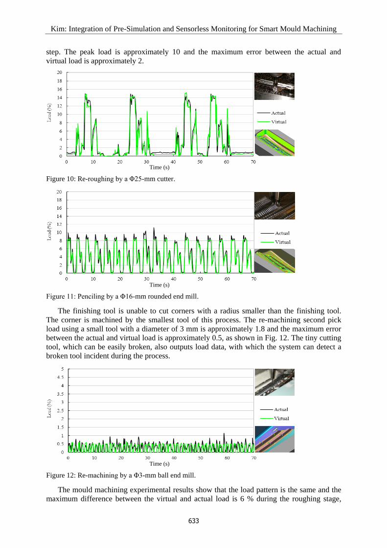
step. The peak load is approximately 10 and the maximum error between the actual and
virtual load is approximately 2.
Time (s)
Figure 10: Re-roughing by a Φ25-mm cutter.
Time (s)
Figure 11: Penciling by a Φ16-mm rounded end mill.
The finishing tool is unable to cut corners with a radius smaller than the finishing tool.
The corner is machined by the smallest tool of this process. The re-machining second pick
load using a small tool with a diameter of 3 mm is approximately 1.8 and the maximum error
between the actual and virtual load is approximately 0.5, as shown in Fig. 12. The tiny cutting
tool, which can be easily broken, also outputs load data, with which the system can detect a
broken tool incident during the process.
Time (s)
Figure 12: Re-machining by a Φ3-mm ball end mill.
The mould machining experimental results show that the load pattern is the same and the
maximum difference between the virtual and actual load is 6 % during the roughing stage,

Kim: Integration of Pre-Simulation and Sensorless Monitoring for Smart Mould Machining
634
12 % during the re-roughing stage, and 20 % during the pencil-machining process. The
experiment proved that the model can be used to monitor roughing, re-roughing, semi-
finishing and pencil-machining, which showed the same actual and virtual load patterns.
In the experiment, the virtual load estimated by the cutting simulation was similar to the
actual spindle load, if the cutting state was normal. In other words, it can be considered that
there is a problem with the machine or cutting tool if the actual load is different from the
virtual load.
The total machining time for the pre-controlled NC data was 39 hours, which is
approximately 30 % less than the predicted time for the original data using a constant feed
rate, because pre-simulation increased the feed rate when a tool moves onto a flat surface that
has already had material removed during the previous step. Machining was stable because
pre-simulation reduced the feed rate at concave corners to limit the maximum cutting force.
The automotive grill cavity was machined unmanned for 34 hours after the roughing process,
because pre-simulation had controlled the cutting conditions to limit the maximum cutting
force, and sensorless monitoring would have stopped the machine tool and sent a message to a
smart phone if the cutting state was different to the pre-simulated data.
4.3 Integration in an Open CNC
An open CNC is configured to a human-machine interface and NC control units. If the
operating system of the human-machine interface is a Windows operating system, software
developed by Visual C++ and Ethernet communication can be installed in the open CNC. The
developed pre-simulation and sensorless monitoring software were integrated in the Windows
operating system of Fanuc 30i and exhibited at SIMTOS 2014, as shown in Fig. 13. The smart
CNC pre-simulates machining and monitors the process. Rapid motion collision data are
replaced by safe height data, and machining is more stabilized and faster as a result of feed
rate pre-control. An automatic tool setter on the machine tool measures tool size before
cutting starts, and checks for tool wear or breakage after machining. Unpredicted collision
error and tool wear is monitored using real-time data and predicted reference data. This
application is not limited to the mould industry, but could also be used in 5-axis machining of
turbine engines and aircraft parts, as shown in Fig. 13 [27].
Figure 13: Pre-simulation and sensorless monitoring integrated in an open CNC.
6. CONCLUSION
Pre-simulation and sensorless monitoring technology that recognise the machining status and
determine better conditions were developed and integrated in an open CNC. Pre-simulation
increases the rapid height to prevent collisions at rapid motion, and regulates feed rate to

Kim: Integration of Pre-Simulation and Sensorless Monitoring for Smart Mould Machining
635
stabilize the process and reduce time. It was evaluated by machining a SM45C block using a
10-mm-diameter ball end mill, and the active feed rate reduced the machining time by up to
36 % without increasing instantaneous maximum cutting forces compared to the protective
cutting conditions, considering the worst case. The simulation technology was
commercialized and has been verified by thousands of mould makers.
It inserted virtual loads, the average of element forces, at every line in the NC data during
the monitoring step. The actual cutting load is computed by removing the friction load and
acceleration load from the spindle load data. Since the acceleration load is too large to be
accurately compensated, the system detected the initial friction load a short time after the
spindle change, and the actual cutting load was calculated by compensating for slow friction
load changes on the cutting process. The monitoring step synchronised the time of the actual
and virtual load data using tool position data, and it detected over cut collisions and tool wear
during the process by comparing the two data.
The system machined a cavity of an automotive grill mould for 34 hours without operator
supervision after a 5-hour roughing process that required changing inserts frequently. Pre-
simulation controlled cutting conditions to achieve process stability, and monitoring would
have stopped the machine tool if real-time data were different to the virtual load. The smart
machining system was able to be integrated in Fanuc 30i, because it obtains real-time status
data and controls process conditions using the local Ethernet without sensors.
ACKNOWLEDGEMENT
Thanks to Kim Du-Jin of NCB Co. Ltd., who has supported the smart mould machining system
research for 10 years. The pre-simulation software NCBrain has been used by thousands of mould
makers, and the smart machining system integrated in Fanuc 30i was exhibited at SIMTOS 2014.
REFERENCES
[1] Hadzistevic, M.; Matin, I.; Hodolic, J.; Vukelic, D.; Vukmirovic, S.; Godec, D.; Nedic, B.
(2014). Rule base reasoning in the knowledge-based mould design system, Technical Gazette,
Vol. 21, No. 5, 1143-1148
[2] Prickett, P. W.; Johns, C. (1999). An overview of approaches to end milling tool monitoring,
International Journal of Machine Tools and Manufacture, Vol. 39, No. 1, 105-122,
doi:10.1016/S0890-6955(98)00020-0
[3] Cerce, L.; Pusavec, F.; Kopac, J. (2015). A new approach to spatial tool wear analysis and
monitoring, Strojniski vestnik – Journal of Mechanical Engineering, Vol. 61, No. 9, 489-497,
doi:10.5545/sv-jme.2015.2512
[4] Nouri, M.; Fussell, B. K.; Ziniti, B. L.; Linder, E. (2015). Real-time tool wear monitoring in
milling using a cutting condition independent method, International Journal of Machine Tools
and Manufacture, Vol. 89, 1-13, doi:10.1016/j.ijmachtools.2014.10.011
[5] Altintas, Y.; Yellowley, I. (1989). In-process detection of tool failure in milling using cutting
force models, Journal of Engineering for Industry, Vol. 111, No. 2, 149-157,
doi:10.1115/1.3188744
[6] Tarn, J. H.; Tomizuka, M. (1989). On-line monitoring of tool and cutting conditions in milling,
Journal of Engineering for Industry, Vol. 111, No. 3, 206-212, doi:10.1115/1.3188751
[7] Kim, S.; Klamecki, B. E. (1997). Milling cutter wear monitoring using spindle shaft vibration,
Journal of Manufacturing Science and Engineering, Vol. 119, No. 1, 118-119, doi:10.1115/
1.2836548
[8] Tlusty, J.; Tarng, Y. S. (1988). Sensing cutter breakage in milling, CIRP Annals – Manufacturing
Technology, Vol. 37, No. 1, 45-51, doi:10.1016/S0007-8506(07)61583-2
[9] Altintas, Y. (1992). Prediction of cutting forces and tool breakage in milling from feed drive
current measurements, Journal of Engineering for Industry, Vol. 114, No. 4, 386-392,
doi:10.1115/1.2900688

Kim: Integration of Pre-Simulation and Sensorless Monitoring for Smart Mould Machining
636
[10] Lee, J. M.; Choi, D. K.; Kim, J.; Chu, C. N. (1995). Real time tool breakage monitoring for NC
milling process, CIRP Annals – Manufacturing Technology, Vol. 44, No. 1, 59-62,
doi:10.1016/S0007-8506(07)62275-6
[11] Kim, T.-Y.; Kim, J.-W. (1996). Adaptive cutting force control for a machining center by using
indirect cutting force measurements, International Journal of Machine Tools and Manufacture,
Vol. 36, No. 8, 925-937, doi:10.1016/0890-6955(96)00097-1
[12] Jesús, R.-T. R.; Gilberto, H.-R.; Iván, T.-V.; Carlos, J.-C. J. (2003). Driver current analysis for
sensorless tool breakage monitoring of CNC milling machines, International Journal of Machine
Tools and Manufacture, Vol. 43, No. 15, 1529-1534, doi:10.1016/j.ijmachtools.2003.08.004
[13] Ulsoy, A. G.; Koren, Y.; Rasmussen, F. (1983). Principal developments in the adaptive control of
machine tools, Journal of Dynamic Systems, Measurement, and Control, Vol. 105, No. 2, 107-
112, doi:10.1115/1.3149640
[14] Yellowley, I. (1985). Observations on the mean values of forces, torque and specific power in the
peripheral milling process, International Journal of Machine Tool Design and Research, Vol. 25,
No. 4, 337-346, doi:10.1016/0020-7357(85)90034-4
[15] Yang, M.-Y., Lee, T.-M. (2002). Hybrid adaptive control based on the characteristics of CNC
end milling, International Journal of Machine Tools and Manufacture, Vol. 42, No. 4, 489-499,
doi:10.1016/S0890-6955(01)00138-9
[16] Deyuan, Z.; Yuntai, H.; Dingchang, C. (1995). On-line detection of tool breakages using
telemetering of cutting forces in milling, International Journal of Machine Tools and
Manufacture, Vol. 35, No. 1, 19-27, doi:10.1016/0890-6955(95)80006-9
[17] Altintas, Y.; Kersting, P.; Biermann, D.; Budak, E.; Denkena, B.; Lazoglu, I. (2014). Virtual
process systems for part machining operations, CIRP Annals – Manufacturing Technology, Vol.
63, No. 2, 585-605, doi:10.1016/j.cirp.2014.05.007
[18] Chaari, R.; Abdennadher, M.; Luati, J.; Haddar, M. (2011). Modelling of the 3D machining
geometric defects accounting for workpiece vibratory behaviour, International Journal of
Simulation Modelling, Vol. 10, No. 2, 66-77, doi:10.2507/IJSIMM10(2)2.173
[19] Kim, S.-J. (2007). Short and safe tool setting by safe space in NC machining, International
Journal of Advanced Manufacturing Technology, Vol. 33, No. 9-10, 1017-1023,
doi:10.1007/s00170-006-0526-2
[20] Zuperl, U.; Cus, F. (2015). Simulation and visual control of chip size for constant surface
roughness, International Journal of Simulation Modelling, Vol. 14, No. 3, 392-403,
doi:10.2507/IJSIMM14(3)2.282
[21] Fussell, B. K.; Jerard, R. B.; Hemmett, J. G. (2000). Robust feedrate selection for 3-axis NC
machining using discrete models, Journal of Manufacturing Science and Engineering, Vol. 123,
No. 2, 214-224, doi:10.1115/1.1365398
[22] Fussell, B. K.; Jerard, R. B.; Hemmett, J. G. (2003). Modeling of cutting geometry and forces for
5-axis sculptured surface machining, Computer-Aided Design, Vol. 35, No. 4, 333-346,
doi:10.1016/S0010-4485(02)00055-6
[23] Altintas, Y.; Spence, A.; Tlusty, J. (1991). End milling force algorithms for CAD systems, CIRP
Annals – Manufacturing Technology, Vol. 40, No. 1, 31-34, doi:10.1016/S0007-8506(07)61927-1
[24] Yun, W.-S.; Cho, D.-W. (2001). Accurate 3-D cutting force prediction using cutting condition
independent coefficients in end milling, International Journal of Machine Tools and
Manufacture, Vol. 41, No. 4, 463-478, doi:10.1016/S0890-6955(00)00097-3
[25] Weinert, K.; Enselmann, A.; Friedhoff, J. (1997). Milling simulation for process optimization in
the field of die and mould manufacturing, CIRP Annals – Manufacturing Technology, Vol. 46,
No. 1, 325-328, doi:10.1016/S0007-8506(07)60835-X
[26] Álvares, A. J.; Ferreira, J. C. E. (2006). WebTurning: Teleoperation of a CNC turning center
through the Internet, Journal of Materials Processing Technology, Vol. 179, No. 1-3, 251-259,
doi:10.1016/j.jmatprotec.2006.03.096
[27] NCB Co. Ltd. NCBrain – Mould Machining Simulation & Optimization Software, from
http://www.ncbrain.com/, accessed on 14-11-2015