Integration of Augmented Reality and indoor positioning ... · PDF fileIntegration of...
8
Integration of Augmented Reality and indoor positioning technologies for on-site viewing of BIM information Hung-Ming Chen a and Ting-Yu Chang a a Department of Civil and Construction Engineering, National Taiwan University of Science and Technology E-mail: [email protected] Abstract - This study applied integrated indoor positioning and augmented reality (AR) technologies to develop an on-site viewing model of BIM. In the proposed model, BIM information is displayed and superimposed on real building elements in 3D component models or surrounding texts using AR technology. The building must have a wireless network environment inside, and each room uses the same set of markers to mark up the building elements in the room. The system uses wireless access points for indoor positioning to identify the user’s location in the room, and then uses markers to identify the building elements in the room. Once a building element is identified, the system retrieves the 3D model or property information from a Cloud-based BIM database and then superimposes them on a view of real building elements. A prototype system was developed based on the proposed model using the WorldViz Vizard platform. The proposed system achieved the integrated display of virtual BIM and real on-site scenes on a head-mounted display (HMD) without manual navigation for model viewing. Keywords - IT Applications; Augmented Reality; Indoor positioning; BIM 1 Introduction Building Information Modeling (BIM) is used to integrate a three-dimensional visual model of construction projects and digital data of various fields with properties into a file or a database with a specific format, allowing project designers, project managers, construction units, owners, and clients to view the design through a three-dimensional visual model and to obtain relevant digital data of the project in a three- dimensional visual model [1]. There are several commercial software systems that are BIM-based, such as Autodesk Revit, Tekla Structures, Bentley Architecture, and Bentley Structural. These commercial BIM software products can integrate 3D models with architectural, structural, electromechanical, air- conditioning, firefighting, and other various field data and store them in a single common BIM project. A feature of these commercial BIM software products is that they primarily support the CAD system of BIM design for a studio work environment. Currently, BIM has been applied successfully during the planning and design phases of projects. However, when one wants to use BIM to support tasks during the construction and maintenance phases, one must bring the BIM to the site and use it. If a user needs to view and query while on the site, the existing approach is still to export the model as 2D floor plans and to bring them on-site to be used with conventional methods, or to use a tablet, notebook, or other mobile devices on the site to run the BIM Viewer software. When a user wants to query the property data of a certain actual building element through BIM Viewer, he/she must first manually search for the 3D scenes in the BIM, find them, and then select the corresponding BIM component to see its relevant components and parameters. Such an approach requires the manual operation of model viewing to return the necessary BIM information to the user. The model is unable to perform automatic interception or to provide immediate feedback regarding the information, and the BIM presented through the computer screen and the actual on-site scene are also provided in two separate views. In this viewing method, the information between the two is less likely to be synchronized and combined. Therefore, BIM applications in engineering are currently mostly used for the planning and design phases. Its application in the construction or maintenance phase is relatively rare. Augmented Reality (AR) is a technology which utilizes computer visualization to superimpose virtual objects on real world images for user interaction [2]. Its mode of operation is to calculate the position and angle of a video device through real-time positioning or image processing, and then superimpose a virtual model and information on the image of the real world. Users can The 31st International Symposium on Automation and Robotics in Construction and Mining (ISARC 2014)
Transcript of Integration of Augmented Reality and indoor positioning ... · PDF fileIntegration of...

Integration of Augmented Reality and indoor positioning technologies for on-site viewing of BIM information
Hung-Ming Chena and Ting-Yu Changa a Department of Civil and Construction Engineering, National Taiwan University of Science and Technology
E-mail: [email protected]
Abstract - This study applied integrated indoor positioning and
augmented reality (AR) technologies to develop an on-site viewing model of BIM. In the proposed model, BIM information is displayed and superimposed on real building elements in 3D component models or surrounding texts using AR technology. The building must have a wireless network environment inside, and each room uses the same set of markers to mark up the building elements in the room. The system uses wireless access points for indoor positioning to identify the user’s location in the room, and then uses markers to identify the building elements in the room. Once a building element is identified, the system retrieves the 3D model or property information from a Cloud-based BIM database and then superimposes them on a view of real building elements. A prototype system was developed based on the proposed model using the WorldViz Vizard platform. The proposed system achieved the integrated display of virtual BIM and real on-site scenes on a head-mounted display (HMD) without manual navigation for model viewing.
Keywords - IT Applications; Augmented Reality; Indoor positioning; BIM
1 Introduction
Building Information Modeling (BIM) is used to integrate a three-dimensional visual model of construction projects and digital data of various fields with properties into a file or a database with a specific format, allowing project designers, project managers, construction units, owners, and clients to view the design through a three-dimensional visual model and to obtain relevant digital data of the project in a three-dimensional visual model [1]. There are several commercial software systems that are BIM-based, such as Autodesk Revit, Tekla Structures, Bentley Architecture, and Bentley Structural. These commercial
BIM software products can integrate 3D models with architectural, structural, electromechanical, air-conditioning, firefighting, and other various field data and store them in a single common BIM project. A feature of these commercial BIM software products is that they primarily support the CAD system of BIM design for a studio work environment. Currently, BIM has been applied successfully during the planning and design phases of projects. However, when one wants to use BIM to support tasks during the construction and maintenance phases, one must bring the BIM to the site and use it. If a user needs to view and query while on the site, the existing approach is still to export the model as 2D floor plans and to bring them on-site to be used with conventional methods, or to use a tablet, notebook, or other mobile devices on the site to run the BIM Viewer software. When a user wants to query the property data of a certain actual building element through BIM Viewer, he/she must first manually search for the 3D scenes in the BIM, find them, and then select the corresponding BIM component to see its relevant components and parameters. Such an approach requires the manual operation of model viewing to return the necessary BIM information to the user. The model is unable to perform automatic interception or to provide immediate feedback regarding the information, and the BIM presented through the computer screen and the actual on-site scene are also provided in two separate views. In this viewing method, the information between the two is less likely to be synchronized and combined. Therefore, BIM applications in engineering are currently mostly used for the planning and design phases. Its application in the construction or maintenance phase is relatively rare.
Augmented Reality (AR) is a technology which utilizes computer visualization to superimpose virtual objects on real world images for user interaction [2]. Its mode of operation is to calculate the position and angle of a video device through real-time positioning or image processing, and then superimpose a virtual model and information on the image of the real world. Users can
The 31st International Symposium on Automation and Robotics in Construction and Mining (ISARC 2014)

instantly and automatically obtain the necessary information based on their location. Its objective is to present virtual objects in the scene of the real world via a video device and to allow users to interact with it. Some studies have attempted to apply AR technology in the field of construction engineering. Park et al. [3] proposed the application of a construction defect management system using BIM and AR. In this system, site executives make use of the BIM data obtained from the database, convert it into a 3D model through smart mobile devices, and demonstrate it on-site. Not only can the on-site workers confirm their work, reducing the errors made, it can also allow an on-site inspector to check if their work is proceeding correctly, thereby reducing defects throughout the construction process. Behzadan and Kamat [4] proposed a teaching system that combines combines AR and real world views of a construction jobsite. In their system, real-time imaging of the construction site can be obtained via an IP-accessible camera and transmitted through the internet to a projection screen for display in a classroom; the positioning system can receive the location of a user and interact with the AR teaching books, designed by the author to achieve the purpose of teaching. Bae et al. [5] adopted a hybrid 4-dimensional AR (HD4AR) system. It is a high-precision mobile AR system that allows on-site workers using mobile devices to capture an image of the building element, enquire, and receive messages in AR as well as overlapping 3D network information that superimposes the real-world. HD4AR can contain important projects, such as the position of the element, progress, specifications, and cost (which have been traditionally difficult to render on the construction site), and act out these projects by superimposing the real world. Users can use a mobile device with a video camera for wireless network positioning, uploading, or downloading the related models, and reading the relevant information. Feng and Kamat [6] employed AR technology to develop a set of indoor Architecture, Engineering, Construction, and Facilities Management (AECFM) systems, with which users can identify AR markers using a smart mobile device. The system calculates the user’s pose, the marker’s pose, and the relative pose of the destination, then reads the data on the database, returns it to the system, and displays it to the user for navigation.
However, most of these studies applied the AR technology on an outdoor on-site construction environment; relatively few studies have applied the AR technology in an indoor environment to support construction and maintenance operations. Therefore, based on the application concept of an outdoor environment AR system, the motivation of this study is
to integrate AR and indoor positioning technologies to superimpose virtual reality images of BIM components and properties inside an indoor work environment, so that user do not require a complicated operation manual for model viewing. The virtual reality images can be superimposed on a single screen, provide an immediate view of BIM, and apply it to support construction and maintenance operations.
2 Objective
The purpose of this study is to propose an on-site view mode of BIM information by integrating AR and indoor positioning technologies. This mode was applied to superimpose the BIM information directly upon a real-time video of the building interior. By overlaying on the architectural elements via an AR device, it displays the 3D model, established using BIM components, and the property parameters of the elements. This is directly presented on-site, providing an immediate feedback to the user.
For this purpose, the indoor positioning technology is first employed to locate the room where the user is. The location of the user is then coordinated with an AR marker to superimpose the created BIM component, including the building elements and the property parameters. With a 3D model to render the exterior of this component and present the properties in text, this information is then superimposed onto an actual building element of the on-site room, affixed with a corresponding marker.
Using Wi-Fi positioning [7] as the indoor positioning technology, viewing of the component through a display requires the corresponding marker. Hence, before using the system, on-site construction and maintenance staff need to set up wireless access point (WAP) for Wi-Fi and configure the markers on building elements such as walls, doors, windows, floors, etc. WAP carries out indoor positioning through the signals emitted by the notebook of this system. Based on the positioning space, the system downloads all BIM components of this space and superimposes virtual reality onto the building elements using the marker.
Users can view the BIM components through wearable video devices and carry out shifting, rotation, scaling, and transparency changes of BIM components.
Before using the in-site viewing mode of BIM information with the integrated AR and indoor positioning technologies, the proposed system must first be pre-set on-site, as described in Figure 1. Its mode of operation is illustrated in Figure 2.
IT APPLICATIONS

Figure 1. Pre-setting process of the proposed system.
Figure 2. Operating process of the proposed system.
The building interior requires the establishment of a wireless network environment. All rooms used a group of identical markers, according to the database of its BIM components, affixed onto each building element inside the space. When a user enters the room on-site, the system starts downloading a reference table from the BIM database. Its contents consist of the rooms of the indoor site and the corresponding BIM component codes. To carry out indoor positioning via WAP and to identify the space where the user is, the system automatically downloads all the BIM components of this space, then coordinates with the marker on the building elements for identification. It can also access the 3D models and related property parameters of the elements from the BIM database based on the identified building elements. Users can instantly view the BIM model and parameters of the target component via a wearable display device as well as using a keyboard or a mouse to rotate, move, and scale the BIM components. They can even change the transparency to facilitate viewing of the BIM components and the hidden components. This integrated model can be conducive to the work of the on-site construction and maintenance staff. They no longer need to view the BIM through
notebooks and tablets. By using the model proposed in this study, users will be able to view the BIM in a way that is more convenient, faster, and more efficient.
3 System Requirements and Mechanisms
In order to achieve the objective mentioned, we investigated the system requirements for each function and proposed the mechanism plan for system operations. Namely, these functions include types and properties of BIM components, database schema for BIM storage, BIM component lookup mechanism, workflow of Wi-Fi positioning technology, connection with BIM database, BIM component information retrieval, marker design and deployment rule, BIM component display mechanism, as well as BIM component model manipulation. The following subsections focus on the analysis and planning description of these 9 directions.
3.1 Types and properties of BIM components
In the field of civil and construction engineering, there are many types of building elements, such as walls, columns, beams, and floors. As the system is a prototype for verifying the feasibility of the model, only 5 building element BIM component types were used. The models were walls, doors, windows, floors, and pipelines which were sourced from Google Sketchup. The models were altered in accordance with the properties of their BIM components in order to match properties of the on-site building elements, such as the size, and species. As noted in Table 1, the properties of BIM components are presented in text format on the system's screen.
Table 1. Types and properties of BIM components in the proposed system.
Component type
3D modelComponent properties
Property presentation
format
Wall position, length, width, height, area,
volume, material
Text or number
Door
Window
Floor
Pipe N/A N/A
3.2 Database schema for BIM storage
The 31st International Symposium on Automation and Robotics in Construction and Mining (ISARC 2014)
In this study, the BIM data sources were obtained from an established cloud database of Apache Hbase [8]. Apache HBase is a structured database system, developed in the Java programming language and set up on distributed systems of the computing cloud. The data is unstructured, untyped, has no functions of JOIN or QUERY, and is not supported by the SQL syntax. The storage method provided can be regarded as an infinite table, in that the information is stored into table, rows, and columns in a logical and organized way. In this study, we took a building as a unit. Each floor was distinguished using rows; information of the BIM components on a floor was stored in the same row. Each BIM component and the BIM components attached on it were taken as a unit of a Column Family; a group of BIM components is stored in a column of a Column Family, as shown in Figure 3. In Figure 3, the name of the table is BIM. Its row is 4F, implying that this row contains information of the fourth floor. The Column Family of B1 contains BIM component data of a wall and hidden pipelines; B2 contains the BIM component of a door; B3 contains the BIM component of a floor and so on.
Figure 3. Conceptual schema of a big table for BIM components.
3.3 BIM component lookup mechanism The Apache HBase adopted in this system was a
BigTable type of NoSQL database system. Because of its non-relational database, data storage and creation do not rely on the primary key, but rely on the structural characteristics of the data. Thus, the form and concept of this database is comparatively different from a traditional relational database.
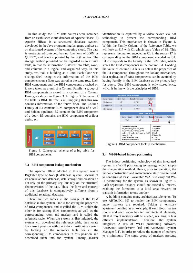
There are two tables in the storage of the BIM database in this system. One is for storing the properties of BIM components, and is called the BIM Table; the other is for storing BIM components as well as the corresponding room and marker, and is called the reference table. When the system is first initiated, the system will download the reference table, then locate the current position with the indoor positioning system by looking up the reference table for all the corresponding BIM components in this position and download them into the system. Finally, marker
identification is captured by a video device via AR technology to present the corresponding BIM component. This mechanism is shown in Figure 4. Within the Family Column of the Reference Table, we will look at 417 with C1 which has a Value of B1. This represents the marker encoded as C1 in the room 417 is corresponding to the BIM component encoded as B1. B1 corresponds to the Family in the BIM table, which stores the BIM components in the column B1. Loading the value of column B1 lets us obtain the properties of the B1 component. Throughout this lookup mechanism, data replication of BIM components can be avoided by having Family in the BIM database as the primary key for query. One BIM component is only stored once, which is in line with the principles of BIM.
Figure 4. BIM component lookup mechanism.
3.4 Wi-Fi-based indoor positioning
The indoor positioning technology of this integrated system is a Wi-Fi positioning technology which adopts the triangulation method. Hence, prior to operation, the indoor construction and maintenance staff on-site need to configure at least 3 available WAPs to carry out Wi-Fi positioning for the system, as shown in Figure 5. Each separation distance should not exceed 50 meters, enabling the formation of a local area network to transmit information to one another.
A building contains many architectural elements. To use ARToolKit [9] to render the BIM components, many markers are required. Taking a ten-story apartment building as an example, if each floor has ten rooms and each room has ten architectural elements, 1000 different markers will be needed, resulting in less efficient implementation. Therefore, the system integrated 2 sets of Wi-Fi positioning software, AeroScout MobileView [10] and AeroScout System Manager [11], in order to reduce the number of markers to a minimum. The same group of markers presents
IT APPLICATIONS

different BIM components in different rooms by using Wi-Fi positioning technology to locate the current position of the user. Then, this system should be able to determine the BIM components for display.
Figure 5. Deployment of WAP.
When installing AeroScout MobileView and
AeroScout System Manager, a database for Wi-Fi positioning will be created automatically in the Microsoft SQL Server. Before use, it requires system settings. First, AeroScout System Manager loads each floor plan of the room on-site. The floor plan must contain the set scale and WAP information, such as location, IP and MAC. Then, AeroScout MobileView is needed to import the set floor plan and the designated room range. Since the system is developed in the programming language of Python, it cannot directly access the information in the Microsoft SQL Server. After setup, the system loads the room information on the Wi-Fi positioning database by having the necessary Pyodbc kit execute SQL queries such as SELECT, WHERE, IN, etc.
3.5 Connection with BIM database
The BIM database contains the necessary information
of the BIM components. Since this system was developed and integrated using the Python programming language, whereas Apache Hbase was developed using the Java programming language, the system cannot directly access the data in Apache Hbase. As a communication bridge, Apache Thrift is required to connect the two different programming languages. Apache Thrift acts like an interpreter of the human world who is able to translate two different programming languages and enable them to communicate.
When using Apache Thrift to connect to Apache Hbase, we must first specify the IP address and port number of the computer with this database. After the system sends a connection request for the database, Apache Hbase will then respond to the request by creating a connection. At this point in time, the built-in commands of Apache Hbase are used to read the tables for downloading. The data is saved into a pre-
established array and the connection with Apache Hbase is finally terminated.
3.6 BIM component information retrieval
After the BIM component information has been downloaded from the BIM database to the system, it cannot be used directly because of the data format and pattern. There is a need to perform BIM data analysis and processing before being used. After the system loads the BIM database via Apache Thrift, the BIM data is in a TCell format, containing the two properties of Timestamp and Value. Timestamp is the corresponding time when the data manipulation occurred, and represents the storage time of the BIM data; Value contains the properties of BIM components, such as the size, types, and materials. The system must first retrieve the data within the Value because its contents are a sequence of characters. Hence, it is required to carry out analysis on the sequence of characters for the required content, such as the size in numerical values, type, and materials of BIM components. Subsequently, these sequences of characters are stored into an array in the format of strings. As the system does not recognize the numerical value, the numerical value portion is converted from the string format to a number format, as listed in Figure 6.
Figure 6. Process for retrieving information regarding a BIM component.
3.7 Marker deployment rule
In this study, the AR system used for integration was
ARToolKit. BIM components and properties need to be presented on the marker. Before usage, the indoor construction and maintenance staff on-site must first carry out configuration for the marker. The connection between a marker and a BIM component is in the form of 1-on-1. According to the BIM database, one BIM
The 31st International Symposium on Automation and Robotics in Construction and Mining (ISARC 2014)

component corresponds to one marker. Thus, all the building elements to be viewed must be configured.
In the system, the design and number of markers can be determined by the user. All markers must comply with the recognizable style of ARToolKit. Users can decide to increase or decrease the number of markers in accordance with the number of BIM components. A marker with a complete design requires the marker capturing program, provided by ARToolKit, to be sent back to the system to be used, as illustrated in Figure 7.
Figure 7. Marker creation module of ARToolKit. According to the spatial form and BIM components,
this study set a group of 9 markers. Each room had the same group of markers with the identification of A, B, C, D, E, F, G, H, and I. Each marker in a different space had corresponding BIM components and possibly displayed a different BIM component, as shown in Figure 8.
Figure 8. The system shows different BIM components on the same marker in different rooms.
3.8 BIM component display mechanism
The BIM component of this system is rendered via
Wi-Fi positioning technology and by superimposing a marker on a target component which is chosen to be viewed. When a user first initiates the system, the system will start downloading the Reference Table from the BIM database. This is a comparison table which contains the BIM components and the corresponding room and marker. Subsequently, the system will drive the notebook of the wearable device to send out a wireless signal to the WAP. After receiving the wireless signal from the notebook, the indoor positioning system will carry out indoor localization on the area where the
user is. Having the Reference Table with the Wi-Fi positioning software to locate the room from the database, the system will load all BIM components of the room, then capture and identify the marker inside the room using a video device with AR technology. Finally, the system can connect the marker with the corresponding BIM components and superimpose the virtual BIM components on the actual building element.
Every minute, the system will load the user’s current location. Based on the user's current location, it will determine the need to re-download the BIM components. If the user enters another room and wants to view its BIM components, this system will re-download all the BIM components of the new room; if user is in the same room, there is no re-downloading required.
The BIM components of this system need to be rendered on a marker. For each room, the connection between the BIM component located in a room and the marker laid inside this room is 1-on-1. One unique BIM component corresponds to one unique marker. Markers need to be placed on the building element to be viewed. All markers and BIM components have their own codes. Markers and BIM components with the same code corresponding to each other to form a connection. When a user views any of the markers inside a room via a wearable AR device, the system will read the BIM component with the code that is consistent with the code of the marker. For instance, a user is currently in the room No. 417; if the user wants to view a door and the door has been affixed with the C1 marker, the system will read all the BIM components of room No. 417 from the downloaded Reference table; when the user views the marker affixed onto this door via a wearable AR device, the system will superimpose the BIM component with the room No. 417 and marker code C1 onto this door. Figure 9 shows snapshots of the superimposed scenes displayed in the prototype system.
Figure 9. Snapshots of the superimposed scenes displayed in the prototype system.
IT APPLICATIONS

3.9 BIM component model manipulation
In order to let a user view the on-site BIM
components more easily, the system provides operating functions to view the model from different angles. Due to the many different kinds of buildings, the format and configuration of the interior may also be different. Viewing of the BIM components may occur under such influences and restrictions. Even during the setup of the system hardware, if the construction or maintenance staff on-site do not affix a marker onto the correct position, the virtual BIM components cannot be superimposed precisely on the building elements, resulting in uneasy viewing. Therefore, the system provides functions of model operation, allowing users to control the model view more conveniently using a keyboard and mouse.
The system includes 6 functions to operate the BIM model. These are model position shift, model angle rotation, model size scaling, model transparency change, on/off property display, and restoring original state, as demonstrated in Figure 10.
Figure 10. Functions for manipulating BIM components.
4 System Framework
The proposed on-site viewing model of BIM information integrated 3 oriented technologies of indoor positioning, AR, and BIM indoor positioning. The source of BIM components is from a well-established Apache Hbase cloud database, and contains two tables. One is the BIM information for the components, designed based on the building interior, and includes 3D models, properties data, geometric data, and its relationship. Another is a comparative table of the building room and the BIM components and allows the downloading of all BIM components of the current room. The AR technology superimposes the virtual reality of BIM components on the on-site building elements by using a video device as well as providing immediate feedback to the user. Figure 11 shows a user equipped with the devices of the proposed system.
Figure 11. User equipped with the devices of the proposed system
The functional framework of the system is described
in Figure 12. IndoorAR4BIM represents the whole system. ReferenceLoader is the loading function on the database for uploading/downloading the Reference Table. ReferenceReader is the query function on the Reference Table; it is responsible for inquiring about information on the Reference table for system operation. IndoorPositioner is the query function of indoor positioning data; it enquires about the information of the indoor positioning database and locates the current position. BIMLoader is the loading function of the BIM data; it loads the BIM information from the BIM database. BIMReader is the reading function of the BIM data, and it is responsible for reading information of downloaded BIM components for system operation. BIMDisplayer is the rendering feature of BIM components; it connects up the BIM components and the marker, rendering the model and properties of BIM components. BIMManipulator contains the operating functions of BIM components; it is used to change the model position, size, angle, transparency, on/off properties display, and to restore the original state of BIM components.
Figure 12. Functional framework of the proposed system
The 31st International Symposium on Automation and Robotics in Construction and Mining (ISARC 2014)

5 Conclusions
This study proposed the on-site view of BIM information by integrating AR and indoor positioning technologies. The purpose is to have a system that uses indoor positioning technology to locate the current indoor position of an on-site user, then downloads BIM-related information from the database. Finally, a 3D model of BIM components and the corresponding properties is superimposed on the building elements via augmented technology, providing an immediate feedback to the user. This system provides (1) Immediacy: It can instantly locate the user's current location and provide immediate feedback to the user. Moreover, users can use a keyboard and mouse to change the position, angle, size, transparency, and on/off property display of BIM components, achieving the purpose of immediate feedback. (2) Synchronization: The models of the BIM components look as if they really exist on the site, achieving synchronization with the user. (3) Convenience: This approach can be more convenient for on-site viewing of BIM. The information is stored in a cloud-based database, and is able to simultaneously support multiple users. This greatly improves the efficiency of on-site construction or maintenance staffs. Summarizing the above, the proposed on-site view of BIM information by integrating AR and indoor positioning technologies can improve the existing view model of BIM to obtain information efficiently and effectively reduce the required operations. Moreover, the immediate feedback of BIM components provided to users for viewing as well as superimposing it on the actual scene in a single synchronized screen should be able to support the on-site operations of construction and maintenance. The limitations of the proposed system are as follows. If the markers are partially blocked, or if the room does not have enough lighting so the camera can detect the markers. Also, the upfront time and energy needed to install markers and then maintain them may be a prohibitive factor.
References
[1] National Institute of Building Sciences, Charter for the National Building Information Model (BIM) Standard Project of the buildingSMARTalliance, The National Building Information Model Standard, 2008.
[2] Shin, D.H. and Dunston, P.S. Identification of application areas for Augmented Reality in industrial construction based on technology
suitability. Automation in Construction, 17(7):882–894, 2008.
[3] Park, C.-S., Lee, D.-Y., Kwon, O.-S. and Wang, X. A framework for proactive construction defect management using BIM, augmented reality and ontology-based data collection Template. In The 12th International Conference on Construction Applications of Virtual Reality, Taipei, Taiwan, 2012.
[4] Behzadan, Amir H. and Kamat, Vineet R. A framework for utilizing context-aware augmented reality visualization in engineering education. In The 12th International Conference on Construction Applications of Virtual Reality, Taipei, Taiwan, 2012.
[5] Bae, H.J., Golparvar-Fard, M. and White, J. Enhanced HD4AR (hybrid 4-dimensional augmented reality) for ubiquitous context-aware AEC/FM Applications. In The 12th International Conference on Construction Applications of Virtual Reality, Taipei, Taiwan, 2012.
[6] Feng, C. and Kamat, Vineet R. Augmented reality markers as spatial indices for indoor mobile AECFM applications. In The 12th International Conference on Construction Applications of Virtual Reality, Taipei, Taiwan, 2012.
[7] Chang, N., Rashidzadeh, R. and Ahmadi, M. Robust indoor positioning using differential Wi-Fi access points. IEEE Transactions on Consumer Electronics, 56(3):1860–1867, 2010.
[8] Apache. Apache HBase. On-line: http://hbase.apache.org.
[9] Kato, H. ARToolKit. On-line: http://www.hitl.washington.edu/artoolkit.
[10] AeroScout. AeroScout MobileView. On-line: http://www.aeroscout.com/mobileview.
[11] AeroScout. AeroScout System Manager. On-line: http://www.aeroscout.com.
IT APPLICATIONS