Integration of an Industrial Robot with the Systems for Image and Voice Recognition
12
SERBIAN JOURNAL OF ELECTRICAL ENGINEERING Vol. 10, No. 1, February 2013, 219-230 219 Integration of an Industrial Robot with the Systems for Image and Voice Recognition Jovica Tasevski 1 , Milutin Nikolić 1 , Dragiša Mišković 1 Abstract: The paper reports a solution for the integration of the industrial robot ABB IRB140 with the system for automatic speech recognition (ASR) and the system for computer vision. The robot has the task to manipulate the objects placed randomly on a pad lying on a table, and the computer vision system has to recognize their characteristics (shape, dimension, color, position, and orientation). The ASR system has a task to recognize human speech and use it as a command to the robot, so the robot can manipulate the objects. Keywords: Industrial robot, Voice recognition, Visual figure recognition. 1 Introduction Rapid technological progress, and the concurrent progress that has been made in robotics, have lead to the situation where the human-robot communication is not any more in science fiction. Until recently, robots have been seen only in the industrial environment, but nowadays they are becoming part of the human’s everyday life. Artificial intelligence is a term that is mostly used together with the concepts of robotics. To make them notable in conjunction with the robot, it is necessary to make them as an active part of everyday life. Humans live in an unstructured environment that has been adjusted to them, and this is one of the reasons why we expect robots to get used to it. Beside the necessary vision system, which is used for any activity in human area, there is a need for robots to talk with humans, and vice versa. There are many ways to make communication between machines and humans. Obviously, for humans, speech represents a most natural way of communication. In order to make it applicable in the communication with machines, the first thing to be done is to develop a system for automatic speech recognition (ASR). To complete the bidirectional communication, a system for speech synthesis is needed. Because of that it is necessary to develop a text-to- speech system (TTS). The system for ASR represents one of the basic components needed to develop speaking technologies, such as: voice interface, systems for multimedia 1 University of Novi Sad, Faculty of Technical Sciences, Trg Dositeja Obradovića 6, 21000 Novi Sad, Serbia; E-mails: [email protected], [email protected], [email protected] UDK: 629.4.016:004.932 DOI: 10.2298/SJEE1301219T
Transcript of Integration of an Industrial Robot with the Systems for Image and Voice Recognition

SERBIAN JOURNAL OF ELECTRICAL ENGINEERING
Vol. 10, No. 1, February 2013, 219-230
219
Integration of an Industrial Robot with the
Systems for Image and Voice Recognition
Jovica Tasevski1, Milutin Nikolić
1, Dragiša Mišković
1
Abstract: The paper reports a solution for the integration of the industrial robot
ABB IRB140 with the system for automatic speech recognition (ASR) and the
system for computer vision. The robot has the task to manipulate the objects
placed randomly on a pad lying on a table, and the computer vision system has to
recognize their characteristics (shape, dimension, color, position, and orientation).
The ASR system has a task to recognize human speech and use it as a command
to the robot, so the robot can manipulate the objects.
Keywords: Industrial robot, Voice recognition, Visual figure recognition.
1 Introduction
Rapid technological progress, and the concurrent progress that has been made in robotics, have lead to the situation where the human-robot communication is not any more in science fiction. Until recently, robots have been seen only in the industrial environment, but nowadays they are becoming part of the human’s everyday life. Artificial intelligence is a term that is mostly used together with the concepts of robotics. To make them notable in conjunction with the robot, it is necessary to make them as an active part of everyday life. Humans live in an unstructured environment that has been adjusted to them, and this is one of the reasons why we expect robots to get used to it. Beside the necessary vision system, which is used for any activity in human area, there is a need for robots to talk with humans, and vice versa. There are many ways to make communication between machines and humans. Obviously, for humans, speech represents a most natural way of communication. In order to make it applicable in the communication with machines, the first thing to be done is to develop a system for automatic speech recognition (ASR). To complete the bidirectional communication, a system for speech synthesis is needed. Because of that it is necessary to develop a text-to-speech system (TTS).
The system for ASR represents one of the basic components needed to develop speaking technologies, such as: voice interface, systems for multimedia
1University of Novi Sad, Faculty of Technical Sciences, Trg Dositeja Obradovića 6, 21000 Novi Sad, Serbia; E-mails: [email protected], [email protected], [email protected]
UDK: 629.4.016:004.932 DOI: 10.2298/SJEE1301219T
J. Tasevski, M. Nikolić, D. Mišković
220
(audio) search, voice dialogue systems, systems for automatic voice translation, etc. Beside standard input-output devices (keyboard, mouse, touch screen, graphical user interface), voice interface is progressively taking an important role. Currently, the most dominant graphical user interface, with all menu items, requires a large amount of operations, even for simple tasks. One of the solutions represents the use of keyboard shortcuts, and all of these could be replaced with voice commands.
If the goal is to achieve the situation in which robot communicates with humans in everyday life, this should be done in a way that makes this interaction as natural as possible. Beside the inaccuracy in speech recognition, or some other technical reasons, misunderstandings between humans and machines, can be caused by the users who produce utterances that fall outside the application's domain, scope, or grammar. Forcing the users to always produce "correct" utterances would significantly limit the naturalness of the communication. That is reason why it is necessary to include adaptive dialogue management, which is used to handle many problems that may occur in the human-machine communication [1].
The system for digital image processing represents an unavoidable part of any newer robotic system, no matter if we are talking about industrial, humanoid, service or any other kind of robots. If we want from the robots to communicate about the environment that surrounds us, it is necessary for the robots to recognize it in a way that humans do.
This paper introduces a solution in which three different subsystems are integrated into one system. It integrates the system for automatic speech recognition and system for speech synthesis (ASR and TTS), digital image processing system, and the robotic system with anthropomorphic robot hand ABB IRB 140. This solution represents an intermediate step for a task where a humanoid robotic hand should be designed and controlled for the project funded by the Ministry of Education and Science of the Republic of Serbia named "Design of Robots as Assistive Technology for the Treatment of Children with Developmental Disorders". The aim of the project is to design the mobile anthropomorphic robot with cognitive characteristics (acronym M.A.R.K.O. – in Serbian: Mobilni Antropomorfni Robot Kognitivnih Osobina). The robot should be capable of communicating with the children with developmental disorders, and it should be able to cooperate with them in solving some common tasks. One of the tasks that should be solved in the cooperation between the robot and the child represents handling exercise, where is expected the manipulation of the objects with different color, size, shape, and thickness [2]. All the interactions during the exercise are to be done by voice communication. Because the development of the anthropomorphic humanoid arm ([2]) requires a significant amount of time, we have decided to use the industrial robotic arm instead. The schematic design of the system is shown in Fig. 1.

Integration of an Industrial Robot with the Systems for Image and Voice Recognition
221
Fig. 1 – Schematic representation of the system design.
The objects used for manipulation are made of wood, and they are standard tool in therapy of children for whom the robot is designed. The objects can differ in shape, where the base of the object can be a triangle, circle, square or rectangle. The base can be smaller or bigger, made in two different sizes. By the color, the objects can be red, blue or yellow. Also, the objects may be thin or thick. In order to make correct classification of the recognized objects we presented the solution with two cameras used in a stereoscopic configuration. Voice recognition is done using AlfaNum ASR system designed for Serbian language. Also, the system for TTS called anReader (AlfaNum) is used.
In the most of human-robot interaction scenarios, the robot performs a preset operation after a voice command is uttered. Besides, these scenarios rarely include an industrial robot [4 – 6]. The systems for the integration of an industrial robot and a voice recognition system have mostly been developed for Anglo-Saxon speaking area. The reason for such a situation is the already developed ASR technology for the English language. One of the best solutions is offered by Microsoft Company (Microsoft Speech Engine, Microsoft Speech Application Programing Interface, Microsoft Speech SDK v5.1). In those systems, the robot is used to execute tasks defined in advance after the received voice command. They represent the task execution where the manipulation of the objects is done in the previously prepared positions (such as pick-and-place tasks), or welding tasks, where the weld line is known in advance. Also, voice recognition is rarely connected to industrial systems. Mostly, it is done for nonindustrial robotics tasks, where the human-robot interaction is more expected.

J. Tasevski, M. Nikolić, D. Mišković
222
In the present solution, the application, developed in C# programming environment, was designed to integrate those systems. All communication between the systems is realized by using TCP/IP (Transmission Control Protocol / Internet Protocol) communication and Serial Peripheral Interface (RS232).
2 System for the Visual Recognition
The system for digital image processing comprised of two AXIS 211 IP cameras and software modules implemented in the programming language C++. The software module employed a vast number of well-known image processing methods. Thus we used an open source library of programming functions for real time computer vision OpenCV 2.3.1 [6]. Also, in order to improve the performance of the system and to cut down execution time, some of the actions were parallelized using Intel Thread Building Blocks [7]. All the objects to be classified were made in two thicknesses, for example, if the object is circular it may be big red thick (thickness 15 mm) and big red thin (thickness 7 mm). In order to classify them properly, the depth information was inevitable. For this purpose, two cameras in a stereoscopic configuration were used. The cameras were placed approximately 70 cm from the objects that are to be classified.
To be able to make precise measurements of the depth, it is necessary to calibrate first each of the cameras, as the lens and CCD (Charge-Coupled Device) sensor imperfections result in a distortion of the acquired image. The calibration served to determine the distortion coefficients, allowing to remove the image distortion that arose due to the imperfectness of our optical system. After calibration and undistortion, the input image is the same as it would have been as if the image acquisition system was ideal. In addition, during the calibration, the relative position of the cameras is acquired. That piece of information is required to perform the rectification and subsequent deter-mination of the disparity map. After calculating the disparity map, the information about the relative position between cameras is used to calculate the position of each image pixel in 3D Cartesian space, whose origin is at the center of the left camera.
All the objects were placed on a pad of the size of A4 paper. The pad was placed on a flat surface – a school table. The coordinate system is placed in the center of the paper with the x-axis in the direction of the wider side of the page and y-axis in the direction of the shorter side. The significance of the pad is twofold. Firstly, it allowed the restoring of the perspective transformation, and secondly it represented a workobject for the industrial robot. That allowed us to create a program for the robot independently of the exact placement of the figures to be classified. Each time when the pad was placed in front of the robot, we define its position in the robot’s coordinate frame by following a standard
Integration of an Industrial Robot with the Systems for Image and Voice Recognition
223
procedure. After that, both robot and image processing module are ‘talking’ in the same coordinate frame, which makes a lot of calculations trivial.
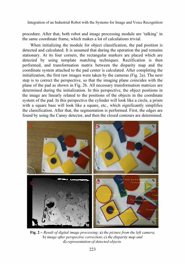
When initializing the module for object classification, the pad position is detected and calculated. It is assumed that during the operation the pad remains stationary. At its four corners, the rectangular markers are placed which are detected by using template matching techniques. Rectification is then performed, and transformation matrix between the disparity map and the coordinate system attached to the pad center is calculated. After completing the initialization, the first raw images were taken by the cameras (Fig. 2a). The next step is to correct the perspective, so that the imaging plane coincides with the plane of the pad as shown in Fig. 2b. All necessary transformation matrices are determined during the initialization. In this perspective, the object positions in the image are linearly related to the positions of the objects in the coordinate system of the pad. In this perspective the cylinder will look like a circle, a prism with a square base will look like a square, etc., which significantly simplifies the classification. After that, the segmentation is performed. First, the edges are found by using the Canny detector, and then the closed contours are determined.
Fig. 2 – Result of digital image processing: a) the picture from the left camera;
b) image after perspective correction; c) the disparity map and
d) representation of detected objects.
J. Tasevski, M. Nikolić, D. Mišković
224
The descriptors used to classify the object's shape are contour area, contour perimeter, dimensions of the minimal enclosing circle, and the minimal area bounding the rectangle. Based on the relationships between these descriptors, the object's shape is determined (circular, triangular, square, and rectangular). The size (small or large) is determined by the contour area.
Based on the mean color, it is determined whether the object is yellow, blue or red. To determine the thickness, it is first necessary to determine the disparity map given in Fig. 2c. Based on the disparity map and transformation matrices found in the initialization coordinates of each pixel relative to the pad are determined. Using that information, thickness of the object is resolved. Since the processes of correcting perspective and segmentation are independent of the process of determining the disparity maps and the spatial coordinates of objects, they are parallelized to speed up the program execution. The result of classification is the vector of classified objects containing fields which define size, shape, color, thickness and x- and y-coordinates of the objects' centers of gravity relative to the pad coordinate frame.
3 Voice Interface System
The voice interface is based on a former R&D of systems for automatic speech recognition and text-to-speech synthesis in Serbian, developed at the Faculty of Technical Sciences, University of Novi Sad, Serbia [8].
The Text-to-Speech engine is provided as a standalone SAPI 5 (Speech Application Programming Interface) speech synthesizer, called anReader. With several male and female voices, it allows various options and settings related to pronunciation. The ASR engine is based on Alfanum ASR, small and medium-sized vocabulary continuous recognizer. The system is speaker independent, phoneme-based, with 3-state HMM (Hidden Markov Model). An elementary HMM model is a triphone model, representing a phoneme in a particular left and right context.
It is important to note that the user is allowed to introduce an arbitrary set of words (i.e., a vocabulary) at the initialization time. A vocabulary is defined by a grammar that describes all utterances that may be produced by the user in the given interaction domain. In order to make the system recognize specific words, a grammar must be defined. This is accomplished using regular expressions, which will be explained later. It is clearly possible to define several grammars and to decide which one is to be used for recognition at each moment. A specific way how to do this depends on the interface used. The input of the recognizer always consists of the speech signal and the name of the grammar. The output consists of two arrays. The first one is the array of recognized words (strings), such as [’MARKO’, ’POMERI’, ’CRVENI’, ’TROUGAO’]. The second one is the array of numeric values, each of them

Integration of an Industrial Robot with the Systems for Image and Voice Recognition
225
defining the reliability of recognition of the corresponding word, i.e.: [73.2, 90.0, 86.7, 91.2]. The reliability values lie in the range 0-100. The exact format of these arrays depends on the interface applied.
The grammars are defined using Backus-Naur form, which will be explained through an example. Here is a simple grammar example for the robot commands:
action = POMERI | POKAŽI; object = TROUGAO | KVADRAT | KRUG | PRAVOUGAONIK; color = CRVENI | PLAVI | ŽUTI; direction = GORE | DOLE | LEVO | DESNO; main = [[$action] [$color] [$figure] [$direction]];
Several elements can be observed: � variables – action, object, color, direction, main. The variable
“main” is the only reserved word and it denotes the main sequence, i.e. what is to be recognized. For that reason it is defined at the end. The other variables can be referenced in any of the following definitions, which can be accomplished by using the prefix “$”;
� mark “|” – denotes a choice. The recognizer will choose one of all the given words;
� square brackets “[ ]” – denote an optional sequence. The recognizer can pass through this word (or the whole rule), or skip it.
An important limitation of the previous approach is that the user is forced to follow the preset grammar. In the reported study, we relax this grammar-related restriction. In order to increase the level of naturalness of the spoken interaction, the users are given only a set of keywords and key-phrases that relate to the entities in the spatial context. The system does not introduce any syntactic expectations. This is illustrated by the following definition of a command:
words = POMERI | POKAŽI | TROUGAO | KVADRAT | KRUG | PRAVOUGAONIK | CRVENI | PLAVI | ŽUTI | GORE | DOLE | LEVO | DESNO; main = [{$words}];
The user is allowed to utter his commands more flexibly. However, the user is also allowed to utter elliptical and context-dependent commands, or even semantically incorrect commands. It is the task of the cognitive system to appropriately interpret such inputs.
The speech recognition engine is built into the ASR IP server. This enables remote access to the server and the application designer needs to incorporate only a simple software client. Actually, we have developed a higher level library which relies on the ASR server and, on the other hand, contains methods
J. Tasevski, M. Nikolić, D. Mišković
226
for communication with the PC application (callback mechanism). In this way, a fully functional communication with the ASR engine is enabled using a very small number of functions.
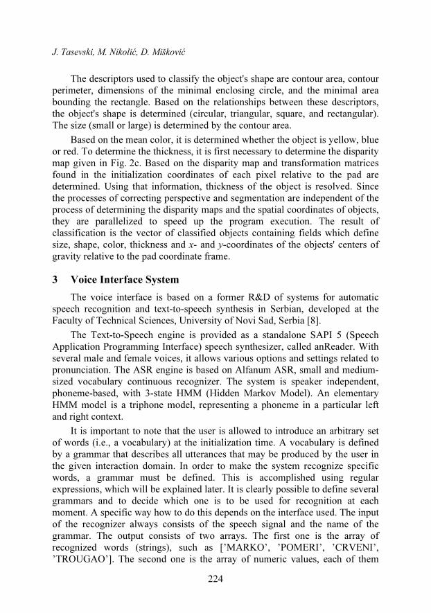
The first library task is to collect samples from the PC microphone. After silence detection, the embedded algorithm sends a recognition request to the server and waits for a response. A schematic presentation of communication protocol between the client and the server application is shown in Fig. 3. The response consists of two arrays. The first one is the array of recognized words, while the second one is the array of numeric values, each of them defining the reliability of recognition of the corresponding word. They are processed in the dialog manager, and the corresponding action is taken. If the result is appropriate and the command is complete, the library sends a request, which causes a change in the robot's behavior. In other cases, the callback mechanism is used to transmit the text to the TTS engine. In this way, a query to the operator for more detailed command specification will be generated.
Fig. 3 – Communication protocol – schematic presentation.
4 Integration with the Robotic System
The systems for voice interface and image processing are connected by using the PC application developed for such task. The whole integration is rounded by connecting the application with the industrial robot ABB IRB140. A schematic illustration of the integrated system is shown in Fig. 4. The cameras, the ASR Server and the PC are connected using the TCP/IP communi-cation via the network router, while the robotic system is connected to the PC using the RS232 serial communication. The IRB140 is an anthropomorphic robotic arm with 6 degrees of freedom. The robot is equipped with IRC5 robot controller, which in our case has only the RS232 serial communication. The software used for programming of the robot is ABB Rapid [9].
To the end of the robot’s arm is connected a tool made of a flexible plastic stick with a rubber layer on its top. The rubber layer is used to increase the

Integration of an Industrial Robot with the Systems for Image and Voice Recognition
227
friction between the stick and the elements on the pad. In this way is achieved the possibility of manipulation of the objects without the need to take them with a gripper. The flexible stick is used in order to prevent accidental damages of the tool, the table or the object, in the case of wrong positioning in the working area.
IP Cameras Router ASR Server
microphone /speaker
ABB IRB 140Robotic system
PC
ASR Client TTS system
Digital image processing system
Fig. 4 – Integrated system – block diagram.
At the start, the robot is in the home position, which can be defined in advance. When the user pronounces a command, the system starts processing, in order to recognize the voice command and objects at the pad. Based on the results from the previous processing, the system is making a decision about the next step. It could be a sentence that should be pronounced to the user via TTS system, or it could be information about the object that should be manipulated. The sentence that is intended to the TTS system occurs when the user fails to pronounce a complete command. In the case when some part is missing, the system will try to find the missing information.
The information about the object consists of seven elements. The first two elements are plane coordinates of the requested element, as the result from the digital image processing. The next information is about the object’s shape (triangular, circular, square or rectangular), then about color (red, blue or yellow), thickness (thick or thin), and size (big or small). After the information about the object, there comes information about the desired movement direction of the selected object, or the information that there will not be any movement (for the case of simply showing the object). In case when there is a desired movement, the system will determine at least two points through which the robot’s tool has to pass. The first of them is always very close to the center point of the requested object, and the second one is calculated based on the first. The two points are sufficient if desired motion is linear. Since there is a movement in the same plane for each object (the plane of the working table), it is possible to define all points by using only two coordinates. The third coordinate can have only two defined values, because of the two different
J. Tasevski, M. Nikolić, D. Mišković
228
thicknesses of the objects. Based on the collected information, we can define the message format in the communication between the PC application and the system for digital image processing as follows:
[<desired shape>, <desired color>, <desired thickness>, <desired size>, <desired action>, <desired direction>].
After receiving this information, the application is ready to send a command to the robot system in the format as follows:
[<x>, <y>, <thickness>, <direction>, <distance>],
where x and y are the plane coordinates; thickness is used to calculate the third
dimension, and the distance value is used to calculate the second point in the working area. After executing the desired command, the robot will go to the home position. At the same time, the robot will notify the application that it is ready for the next command.
5 Experiment and Conclusion
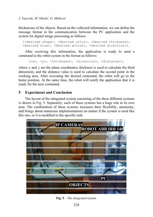
The layout of the integrated system consisting of the three different systems is shown in Fig. 5. Separately, each of these systems has a huge role in its own area. The combination of these systems increases their flexibility, autonomy, and brings about numerous implementations no matter if the system is used like this one, or it is modified to the specific task.
IP CAMERAS
ROBOT ABB IRB 140
OBJECTS
PC
Fig. 5 – The integrated system.

Integration of an Industrial Robot with the Systems for Image and Voice Recognition
229
Further development and research directions will be to make the system more robust, in order to manipulate a larger number of objects, and to perform more complex manipulation (not only in the working plane, but also in the whole working space). Finally, the main idea would be to implement this solution onto the anthropomorphic humanoid robotic arm, instead of the industrial one.
The solution presented in this paper, may have application in industrial systems where there is a need for developing flexible manufacturing cells or lines, especially if there is a need for consistent communication between the robot and humans involved into the manufacturing process. Also, the solution can be implemented in some assembling processes and service operations, as well as to have medical applications, where the medical staff can use the robot in some sensitive and demanding processes.
This solution can be implemented in any situation where the robot can be used as manpower, and where human will give commands and make decisions. The ability of the robots to understand human's speech, to make an answer in the right context, and to be able to see human's environment in the same way as humans do, will make huge improvement in the usage of modern technology in human's everyday life.
6 Acknowledgment
The presented study is performed as part of the projects “Design of Robots as Assistive Technology for the Treatment of Children with Developmental Disorders” (III44008), and “Development of Dialogue Systems for Serbian and Other South Slavic Languages”' (TR32035) funded by the Ministry of Education and Science of the Republic of Serbia. The responsibility for the content of this paper lies with the authors.
7 References
[1] M. Gnjatović: Adaptive Dialogue Management in Human-Machine Interaction, PhD Thesis,
Otto-von-Guericke-University, Magdeburg, Germany, 2009.
[2] S. Savić, M. Jurošević: Design of Modular Robot Arm with Seven Degrees of Freedom,
ETRAN Conference, Zlatibor, Serbia, 11 – 14 June, 2012. (In Serbian).
[3] J.N. Pires: Robot-by-voice: Experiments on Commanding an Industrial Robot using the Human
Voice, Industrial Robot: An International Journal, Vol. 32, No. 6, 2005, pp. 505 – 511.
[4] J.N. Pires, G. Veiga, R. Araujo: Programing-by-demonstration in the Coworker Scenario for
SMEs, Industrial Robot: An International Journal, Vol. 36, No. 1, 2009, pp. 73 – 83.
[5] D. Rambabu, R. Nagaraju, B. Venkatesh: Speech Recognition of Industrial Robot,
International Journal of Computational Mathematical Ideas, Vol. 3, No. 2, 2011, pp. 92 – 98.
[6] R. Laganière: OpenCV 2 Computer Vision Application Programming Cookbook, Packt
Publishing, Birmingham, UK, 2011.
[7] J. Reinders: Intel Threading Building Blocks, O’ Reilly, Birmingham, UK, 2007.
J. Tasevski, M. Nikolić, D. Mišković
230
[8] V. Delic, D. Pekar, R. Obradovic, N. Jakovljevic, D. Miskovic: A Review of AlfaNum
Continuous Automatic Speech Recognition System, XII International Conference “Speech
and Computer”, Moscow, Russia, 15 – 18 Oct. 2007.
[9] ABB Rapid Reference Manual, ABB Automation Technologies Products AB, Robotics,
Vasteras, Sweden, 2005.


![Gesture Recognition System for Human-Robot Interaction and ... · the service robot have been proposed such as voice recognition [1], gesture recognition [2-6], and so on. There have](https://static.fdocuments.us/doc/165x107/60021267a14a4e19a73d62fe/gesture-recognition-system-for-human-robot-interaction-and-the-service-robot.jpg)