Integration Guide Symbio® 210 Programmable Controller
28
Symbio® 210 Programmable Controller For Variable-Air-Volume (VAV) Boxes Integration Guide June 2021 BAS-SVP043A-EN SAFETY WARNING Only qualified personnel should install and service the equipment. The installation, starting up, and servicing of heating, ventilating, and air-conditioning equipment can be hazardous and requires specific knowledge and training. Improperly installed, adjusted or altered equipment by an unqualified person could result in death or serious injury. When working on the equipment, observe all precautions in the literature and on the tags, stickers, and labels that are attached to the equipment.
Transcript of Integration Guide Symbio® 210 Programmable Controller

Symbio® 210 Programmable
ControllerFor Variable-Air-Volume (VAV) Boxes
Integration Guide
June 2021 BAS-SVP043A-EN
SAFETY WARNINGOnly qualified personnel should install and service the equipment. The installation, starting up, and servicing of heating, ventilating, and air-conditioning equipment can be hazardous and requires specific knowledge and training. Improperly installed, adjusted or altered equipment by an unqualified person could result in death or serious injury. When working on the equipment, observe all precautions in the literature and on the tags, stickers, and labels that are attached to the equipment.

Introduction
Warnings, Cautions, and Notices
Safety advisories appear throughout this manual as required. Your personal safety and the proper operation of this machine depend upon the strict observance of these precautions.
Important Environmental Concerns
Scientific research has shown that certain man-made chemicals can affect the earth’s naturally occurring stratospheric ozone layer when released to the atmosphere. In particular, several of the identified chemicals that may affect the ozone layer are refrigerants that contain Chlorine, Fluorine and Carbon (CFCs) and those containing Hydrogen, Chlorine, Fluorine and Carbon (HCFCs). Not all refrigerants containing these compounds have the same potential impact to the environment. Trane advocates the responsible handling of all refrigerants-including industry replacements for CFCs and HCFCs such as saturated or unsaturated HFCs and HCFCs.
Important Responsible Refrigerant Practices
Trane believes that responsible refrigerant practices are important to the environment, our customers, and the air conditioning industry. All technicians who handle refrigerants must be certified according to local rules. For the USA, the Federal Clean Air Act (Section 608) sets forth the requirements for handling, reclaiming, recovering and recycling of certain refrigerants and the equipment that is used in these service procedures. In addition, some states or municipalities may have additional requirements that must also be adhered to for responsible management of refrigerants. Know the applicable laws and follow them.
The three types of advisories are defined as follows:
WARNING Indicates a potentially hazardous situation which, if not avoided, could result in death or serious injury.
CAUTIONsIndicates a potentially hazardous situation which, if not avoided, could result in minor or moderate injury. It could also be used to alert against unsafe practices.
NOTICE Indicates a situation that could result in equipment or property-damage only accidents.
WARNING
Proper Field Wiring and Grounding Required!
Failure to follow code could result in death or serious injury. All field wiring MUST be performed by qualified personnel. Improperly installed and grounded field wiring poses FIRE and ELECTROCUTION hazards. To avoid these hazards, you MUST follow requirements for field wiring installation and grounding as described in NEC and your local/state electrical codes. Failure to follow code could result in death or serious injury.
©2021 Trane BAS-SVP043A-EN

Introduction
Copyright
This document and the information in it are the property of Trane, and may not be used or reproduced in whole or in part without written permission. Trane reserves the right to revise this publication at any time, and to make changes to its content without obligation to notify any person of such revision or change.
Trademarks
All trademarks referenced in this document are the trademarks of their respective owners.
WARNING
Personal Protective Equipment (PPE) Required!
Failure to wear proper PPE for the job being undertaken could result in death or serious injury. Technicians, in order to protect themselves from potential electrical, mechanical, and chemical hazards, MUST follow precautions in this manual and on the tags, stickers, and labels, as well as the instructions below:
• Before installing/servicing this unit, technicians MUST put on all PPE required for the work
being undertaken (Examples; cut resistant gloves/sleeves, butyl gloves, safety glasses, hard
hat/bump cap, fall protection, electrical PPE and arc flash clothing). ALWAYS refer to
appropriate Safety Data Sheets (SDS) and OSHA guidelines for proper PPE.
• When working with or around hazardous chemicals, ALWAYS refer to the appropriate SDS
and OSHA/GHS (Global Harmonized System of Classification and Labeling of Chemicals)
guidelines for information on allowable personal exposure levels, proper respiratory
protection and handling instructions.
• If there is a risk of energized electrical contact, arc, or flash, technicians MUST put on all PPE
in accordance with OSHA, NFPA 70E, or other country-specific requirements for arc flash
protection, PRIOR to servicing the unit. NEVER PERFORM ANY SWITCHING,
DISCONNECTING, OR VOLTAGE TESTING WITHOUT PROPER ELECTRICAL PPE AND ARC
FLASH CLOTHING. ENSURE ELECTRICAL METERS AND EQUIPMENT ARE PROPERLY RATED
FOR INTENDED VOLTAGE.
WARNING
Follow EHS Policies!
Failure to follow instructions below could result in death or serious injury.
• All Trane personnel must follow the company’s Environmental, Health and Safety (EHS)
policies when performing work such as hot work, electrical, fall protection, lockout/tagout,
refrigerant handling, etc. Where local regulations are more stringent than these policies,
those regulations supersede these policies.
• Non-Trane personnel should always follow local regulations.
BAS-SVP043A-EN 3

Table of Contents
4 BAS-SVP043A-EN
Overview . . . . . . . . . . . . . . . . . . . . . . . . . . . . . . . . . . . . . . . . . . . . . . . . . . . . . . . . . 5
BACnet Protocol . . . . . . . . . . . . . . . . . . . . . . . . . . . . . . . . . . . . . . . . . . . . . . . . . . . 5
Rotary Switches and LEDs . . . . . . . . . . . . . . . . . . . . . . . . . . . . . . . . . . . . . . . . . . 6
Rotary Switches . . . . . . . . . . . . . . . . . . . . . . . . . . . . . . . . . . . . . . . . . . . . . . . . . 6
LEDs Description, Behavior, and Troubleshooting . . . . . . . . . . . . . . . . . . . . 7
24 Vac Measurement . . . . . . . . . . . . . . . . . . . . . . . . . . . . . . . . . . . . . . . . . . . 11
Connecting to Tracer TU and Configuring Settings . . . . . . . . . . . . . . . . . . . . . 12
Starting a Session of Tracer TU and Making Direct Connection . . . . . . . . . 12
Change Baud Rate . . . . . . . . . . . . . . . . . . . . . . . . . . . . . . . . . . . . . . . . . . . . . . 12
Change Device ID . . . . . . . . . . . . . . . . . . . . . . . . . . . . . . . . . . . . . . . . . . . . . . 13
BACnet Data Points and Configuration Property Definitions . . . . . . . . . . . . . . 14
BACnet Protocol Implementation Conformance Statement (PICS) . . . . . . 14Standardized Device Profile (Annex L) . . . . . . . . . . . . . . . . . . . . . . . . . . . 14Interoperability Building Blocks (Annex K) . . . . . . . . . . . . . . . . . . . . . . . . 14Segmentation Capability . . . . . . . . . . . . . . . . . . . . . . . . . . . . . . . . . . . . . . 15Object Types . . . . . . . . . . . . . . . . . . . . . . . . . . . . . . . . . . . . . . . . . . . . . . . . 15
BACnet Protocol . . . . . . . . . . . . . . . . . . . . . . . . . . . . . . . . . . . . . . . . . . . . . . . . . . 19Data Link Layer Options . . . . . . . . . . . . . . . . . . . . . . . . . . . . . . . . . . . . . . . 19Device Address Binding . . . . . . . . . . . . . . . . . . . . . . . . . . . . . . . . . . . . . . . 19Networking Options . . . . . . . . . . . . . . . . . . . . . . . . . . . . . . . . . . . . . . . . . . 19Character Sets . . . . . . . . . . . . . . . . . . . . . . . . . . . . . . . . . . . . . . . . . . . . . . . 19
Object and Diagnostic Data Points . . . . . . . . . . . . . . . . . . . . . . . . . . . . . . . . 20
VAV Alarming . . . . . . . . . . . . . . . . . . . . . . . . . . . . . . . . . . . . . . . . . . . . . . . . . . . . 33
Additional Resources . . . . . . . . . . . . . . . . . . . . . . . . . . . . . . . . . . . . . . . . . . . . . . 33

Overview
The Symbio® 210 is a programmable controller. Programming is done through the Tracer Graphical Programming software or through configuration with Tracer TU. The Symbio 210 controller is primarily designed for VAV box control.
The intent of this guide is to provide BACnet integration information when the controller ships with factory downloaded programs or is programmed using the VAV equipment configuration in Tracer TU. In addition, this controller can be configured from the factory for the following application programs: Space Temperature Control (STC), Ventilation Flow Control (VFC), and Flow Tracking Control (FTC). For more details on these applications, refer to the Symbio® 210 Programmable VAV Box Controller Installation, Operation, and Maintenance Manual (BAS-SVX084*-EN).
This guide provides the following:
• A brief overview of the BACnet protocol
• An explanation of the Symbio 210 device rotary switches
• Connecting to Tracer TU and configuring controller settings
• Data point configuration property definitions
• Tables listing object data points
• Additional resources
Note: Users of this guide should have basic knowledge of the BACnet protocol. For more detailed information about this protocol, visit the organization’s web site at, www.bacnetinternational.org. In addition, there are other helpful documents to reference when using this integration guide listed in “Additional Resources,” p. 25.
BACnet Protocol
The Building Automation and Control Network (BACnet) protocol is a standard that allows building automation systems or components from different manufacturers to share information and control functions. BACnet provides building owners the capability to connect various types of building control systems or subsystems together for many uses. In addition, multiple vendors can use this protocol to share information for monitoring and supervisory control between systems and devices in a multi-vendor interconnected system.
The BACnet protocol identifies standard objects (data points) called BACnet objects. Each object has a defined list of properties that provide information about that object. BACnet also defines a number of standard application services that are used to access data and manipulate these objects and provides a client/server communication between devices. For more information on BACnet protocol, refer to “Additional Resources,” p. 25.
BACnet Testing Laboratory (BTL) Certification
Symbio 210 supports the BACnet communication protocol and has been designed to meet the requirements of the Building Controller (BC) profile. For more details, refer to the BTL web site at www.bacnetassociation.org.
BAS-SVP043A-EN 5

Rotary Switches
Rotary Switches
This section provides information about Symbio 210 rotary switches. For troubleshooting, refer to the Symbio® 210 Programmable Variable-Air-Volume(VAV) Box Controller Installation, Operation, and Maintenance Manual (BAS-SVX084*-EN).
There are three rotary switches on the front of the controllers that are used to define a three-digit address when they are installed on a BACnet communications network. The three-digit address setting is used as both the BACnet MAC address and the BACnet device ID.
Note: All devices are MSTP masters with valid MAC addresses of 001 to 127 for BACnet.
Figure 1. Setting rotary switches
Important: Each controller on the BACnet/MSTP link must have a unique rotary switch setting. Otherwise, communication problems will occur.
ADDRESS0 1
23
456
78
9
x1
0 12
3
456
78
9
x10
0 1
23
456
78
9
x100
Use a 1/8 in. (3 mm) flathead screwdriverto set rotary switches. Switches rotatein either direction.
Before
After
6 BAS-SVP043A-EN

Using Symbio UI to Configure Settings
Using Symbio UI to Configure Settings
Symbio UI is a built-in web-based user interface that is used for basic setup and configuration of the Symbio 210. This interface replaces the need to use the BACnet Setup Tool to configure BACnet protocol settings and allows users to select BAS or local for the source on many sensors and setpoints on the equipment.
Connecting to Symbio UI
1. Connect a laptop to the USB service tool port using a USB 2.0 A to B cable. Symbio UI can only be accessed over USB connection.
2. Open a web browser and connect to http://198.80.18.1 to access Symbio UI.
Configuring BAS Control SelectionSymbio UI allows users to select which sensors and setpoints use values communicated over the Building Automation System (BAS) vs using the local sensor. This can be selected for a varying number of sensors and setpoints depending on how the equipment is configured.
WARNING
1. With Symbio UI open in a web browser navigate to the Tools menu on the left-hand navigation.
2. In the Tools menu select BAS Control Selection to open the selection tool.
3. In the BAS Control Selection tool use the toggle to select from BAS or Local as the source of information for the selected sensor or setpoint.
4. Select Save button in bottom right to save changes.
BAS-SVP043A-EN 7

Using Symbio UI to Configure Settings
Figure 2. BAS Control Selection
Configuring Regional Specifications
Symbio UI allows users to set the date, time and time zone. IP based controllers will also have the ability to configure NTP server for time synchronization.
1. In Symbio UI, navigate to the Installation menu on the left-hand navigation.
2. Select Regional Specifications.
3. Select Edit to change the settings.
4. Fill in the date, time and time zone for the controller.
5. Select Save button in bottom right to save changes.
8 BAS-SVP043A-EN

Using Symbio UI to Configure Settings
Configuring System Units
Symbio UI allows users to set the desired System Units of the controller. This will change the unit communicated over BACnet. Making changes to System Units will restart the controller and equipment will be inoperable for a brief period of time.
1. With Symbio UI open in a web browser, navigate to the Installation menu on the left-hand navigation.
2. In the Installation menu, select System Units.
3. In the System Units window, use the toggle at the top of the page to switch between Inch-Pound (IP) and System International (SI) units.
4. Select Save button in bottom right to save changes. Saving changes will restart the controller and equipment will be inoperable for a brief period of time.
Note: It may not be possible to change the System Units because TGP2 programs exist that could not be converted. Tracer TU must be used to rectify this issue.
Configuring Identification and Communications
Symbio UI allows users to set the Name, Description, and Location of the controller as well as the communication protocol and associated settings.
Identification Settings:
1. With Symbio UI open in a web browser, navigate to the Installation menu on the left-hand navigation.
2. In the Installation menu, select Identification and Communications.
3. In the Identification and Communications window, select the Identification tab.
4. Use the Edit button at the top of the page to change the Name, Description, and Location fields.
BAS-SVP043A-EN 9

Using Symbio UI to Configure Settings
5. Select Save button in bottom right to save changes.
Protocol Settings:
1. With Symbio UI open in a web browser, navigate to the Installation menu on the left-hand navigation.
2. In the Installation menu, select Identification and Communications.
3. In the Identification and Communications window, select the Protocol Configuration tab.
4. Use the Edit button at the top of the page to change Protocol Settings.
5. Click Save in bottom right to save changes. Saving changes will restart the controller and equipment will be inoperable for a brief period of time.
10 BAS-SVP043A-EN

Object and Diagnostic Data Points
IP Settings:
1. With Symbio UI open in a web browser, navigate to the Installation menu on the left-hand navigation.
2. In the Installation menu, select Identification and Communications.
3. In the Identification and Communications window, select the IP Configuration tab.
4. Use the Edit button at the top of the page to change Protocol Settings.
5. Click Save in bottom right to save changes. Saving changes will restart the controller and equipment will be inoperable for a brief period of time.
Object and Diagnostic Data Points
For quick reference, the following tables are listed and sorted two different ways. Table 1 through Table 8 are listed by input/output type and sorted by object type. For easy reference, Table 9, p. 18 lists all object types provided in the tables 3 through 10 and is sorted by object name. In addition, this table provides specific configurations that apply to each point shown under the last five columns. Refer to the footnote at the end of this table for information related to the entries in these columns.
Note: Not all points are available to the user. The available data points are defined and dependent on the type of equipment and options.
Table 1. Analog inputs
Object Type Object Name
Units of Measure
MinimumMaximum Description
AI1 Space Temperature Local Temperature (°F or °C)
15°C (59°F)50°C (122°F) Temperature sensor in the space.
AI2 Space Temperature Setpoint Local Temperature (°F or °C)
10°C (50°F)29.4°C (84.92°F) Zone sensor thumbwheel.
BAS-SVP043A-EN 11

Object and Diagnostic Data Points
AI3 Pressure 1
Gaseous Pressure (in H2O, in Hg, mm H2O, mm Hg, Pa, kPa)
0 pascals498 pascals
• Pressure across the flow ring.• 120% flow indicates 2 in H2O (498 pascals) across flow ring.
AI4 Discharge Air Temperature Temperature (°F or °C)
-40°C (-40°F)100°C (212°F) Discharge air temperature sensor wire to the controller.
AI5 Supply Air Temperature Local Temperature (°F or °C)
-40°C (-40°F)100°C (212°F) Supply air temperature sensor wired to the controller.
AI6 Actual Air Valve Position Percentage (%) Valve position on % open.
AI7 Actual Reheat Position Percentage (%) Reheat valve position in % open.
AI8 Space CO2 Concentration Local Parts-per-million 0 ppm5,000 ppm Space CO2 concentration in ppm.
AI9 Air Valve 1 Stroke Time None
60,000 milliseconds570,000 milliseconds
Air valve stroke time in milliseconds (100-millisecond resolution).
AI10 Minimum Actuator Time None 100 milliseconds1,000 milliseconds
• Air valve minimum actuator time 100-millisecond increments.• Minimum 500 milliseconds.
AI11 Water Valve Maximum Stroke Time None 60 milliseconds240 milliseconds This is used for remote or local modulating water heat valve. In milliseconds.
AI12 Water Valve Minimum Actuator Time None 100 milliseconds1,000 milliseconds Water valve minimum actuator time 100-millisecond increments.
Table 2. Analog output
Object Type Object Name
Units of Measure
MinimumMaximum Description
AO1 Air Valve Drive Command Percentage (%) Value of AO is the requested % open.Note: Refer to Actual Air Valve Position.
AO2 Supply Fan Speed Percentage (%) Supply fan in percent. For single-speed fans (0% = OFF, 100% = ON).
AO3 Heating Valve Command Percentage (%) Modulating reheat valve. This is the requested position in percent.Note: Refer to Heating Capacity Secondary for actual water valve position.
Table 1. Analog inputs (continued)
Object Type Object Name
Units of Measure
MinimumMaximum Description
12 BAS-SVP043A-EN

Object and Diagnostic Data Points
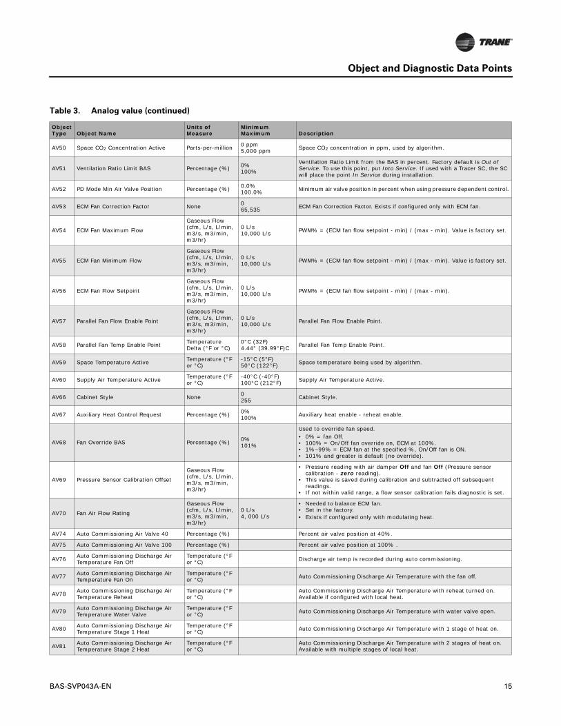
Table 3. Analog value
Object Type Object Name
Units of Measure
MinimumMaximum Description
AV2 Air Flow Minimum Setpoint Active
Gaseous Pressure (in H2O, in Hg, mm H2O, mm Hg, Pa, kPa)
Air Flow Minimum Setpoint Active.
AV8 Air Flow Nominal Status
Gaseous Pressure (in H2O, in Hg, mm H2O, mm Hg, Pa, kPa)
0 L/s10,000 L/s Nominal airflow set by configurator based on the unit size selected.
AV9 Reheat Enable Point Temperature (°F or °C)
10°C (50°F)100°C (212°F) Reheat Enable Point.
AV10 Auto Changeover Point Temperature (°F or °C)
10°C (50°F)100°C (212°F Auto Changeover Point.
AV12 Heat Output Secondary Status Percentage (%)
Percent output value (not the same as capacity in all cases). • For modulating this is the valve position.• For PWM, this is the capacity.• For Staged, are the discrete values for each stage (for example, 2 stage is
0%, 50%, 100% or 3 stage is 0%, 33%, 66%, 100%).
AV13 Air Flow Setpoint Active
Gaseous Flow (cfm, L/s, L/min, m3/s, m3/min, m3/hr)
Air Flow Setpoint Active.
AV14 Space Temperature BAS Temperature (°F or °C)
-15°C (5°F)50°C (122°F)
Space temperature communicated from BAS. If used, the Tracer SC will write to this point once every 15 minutes, but ONLY if this point is put into Service. If the point is in service, but not written to every 15 minutes the controller will put the point into fault status. Factory default is Out of Service. To use this point, put Into Service.
AV15 Air Flow Override Percent None 0%100% Air Flow Override Percent.
AV16 Discharge Air Temperature Setpoint BAS
Temperature (°F or °C)
-7.22°C (19.00°F)21.11°C (69.99°F)
• Only for VFC configuration.• Discharge air temp setpoint communicated from BAS.• Factory default is Out of Service. To use this point, put Into Service.
AV18 Air Flow Gain None 0.0002.000
Default setting is 1.0 and can be edited based on the results of an air balancing test.
AV19 Air Flow Measurement Offset Percentage (%) -50.000%50.000% Set when air balancing.
AV20 Discharge Air Flow
Gaseous Flow (cfm, L/s, L/min, m3/s, m3/min, m3/hr)
Pressure sensor 1 value converted to flow.
AV21 Outdoor Air Low Limit Temperature (°F or °C)
-6.66°C (20.12°F)7.22°C (44.99°F) VFC freeze protection.
AV22 Space CO2 Concentration BAS Parts-per-million 0 ppm5,000 ppm
Space CO2 concentration communicated from the BAS in ppm. If used, the system will write to this point once every 15 minutes. Otherwise, the controller will put the point into fault status. Factory default is Out of Service. To use this point, put Into Service.
AV23 Unoccupied Cooling Setpoint Temperature (°F or °C)
4.44°C (20.12°F)46.11°C (114.99°F)
Unoccupied Cooling Setpoint.
AV24 Unoccupied Heating Setpoint Temperature (°F or °C)
4.44°C (20.12°F)46.11°C (114.99°F)
Unoccupied Heating Setpoint.
AV25 Air Flow Setpoint BAS
Gaseous Flow (cfm, L/s, L/min, m3/s, m3/min, m3/hr)
0 L/s65,534 L/s Communicated airflow setpoint used for flow tracking units.
AV26 Air Flow Offset
Gaseous Flow (cfm, L/s, L/min, m3/s, m3/min, m3/hr)
-10,000 L/s10,000 L/s Flow set point of Flow Tracking box relative to supply air VAV box.
AV27 Space Temperature Setpoint BAS Temperature (°F or °C)
-10°C (14°F)35°C (95°F)
Communicated setpoint. Factory default is Out of Service. To use this point, put Into Service. If used with a Tracer SC, the SC will place the point In Service during installation.
AV28 Space Temperature Setpoint Active Temperature (°F or °C)
-5.6°C (21.92°F)56.1°C (132.98°F) Space temperature setpoint being used by algorithm.
BAS-SVP043A-EN 13

Object and Diagnostic Data Points
AV29 Supply Air Temperature BAS Temperature (°F or °C)
0°C (32°F)100°C (212°F)
Supply air temperature communicated from BAS. Factory default is Out of Service. To use this point, put Into Service. If used with a Tracer SC, the SC will place the point In Service during installation.
AV30 Occupied Offset Temperature Delta (°F or °C)
4.44°C (20.12°F)46.11°C (114.99°F)
Setpoint offset used during occupied mode.
AV31 Air Flow Setpoint Minimum Local Heat
Gaseous Flow (cfm, L/s, L/min, m3/s, m3/min, m3/hr)
0 L/s10,000 L/s Reheat minimum used when local heat is On.
AV33 Occupied Bypass Time None 0 minutes240 minutes
The number of minutes the unit will stay in occupied bypass after initiated by time override button.
AV34 Standby Offset Temperature Delta (°F or °C)
4.44°C (20.12°F)46.11°C (114.99°F)
Setpoint offset used during occupied standby mode.
AV35 Ventilation Setpoint Active
Gaseous Flow (cfm, L/s, L/min, m3/s, m3/min, m3/hr)
Ventilation Setpoint Active.
AV36 Ventilation Ratio Percentage (%) 0%–100%. Percentage indicates the required ratio or outdoor air-to-primary air needed to meet zone ventilation requirements.
AV37 Space Temp Setpoint Default Temperature (°F or °C)
4.44°C (20.12°F)46.11°C (114.99°F)
Default space temperature setpoint stored in the controller and set by service tool.
AV38 Ventilation Setpoint Local
Gaseous Flow (cfm, L/s, L/min, m3/s, m3/min, m3/hr)
0 L/s10,000 L/s Ventilation Setpoint Local.
AV39 Discharge Air Temp Setpoint Local Temperature (°F or °C)
-7.22°C (19.00°F)21.11°C 69.99°F)
• Only for VFC configuration.• Discharge air temp setpoint from wired sensor.
AV40 Space CO2 Limit Parts-per-million 0 ppm2,000 ppm Point where CO2 demand ventilation ends in ppm.
AV41 Space CO2 Low Limit Parts-per-million 0 ppm2,000 ppm Point where CO2 demand ventilation begins in ppm.
AV42 Air Flow Setpoint Minimum
Gaseous Flow (cfm, L/s, L/min, m3/s, m3/min, m3/hr)
0 L/s10,000 L/s Air Flow Setpoint Minimum.
AV43 Air Flow Setpoint Minimum Standby
Gaseous Flow (cfm, L/s, L/min, m3/s, m3/min, m3/hr)
0 L/s10,000 L/s Air Flow Setpoint Minimum Standby.
AV44 Air Flow Setpoint Minimum Standby Heat
Gaseous Flow (cfm, L/s, L/min, m3/s, m3/min, m3/hr)
0 L/s10,000 L/s Air Flow Setpoint Minimum Standby Heat.
AV45 Air Flow Setpoint Minimum Heat
Gaseous Flow (cfm, L/s, L/min, m3/s, m3/min, m3/hr)
0 L/s10,000 L/s Air Flow Setpoint Minimum Heat.
AV46 Air Flow Setpoint Maximum Heat
Gaseous Flow (cfm, L/s, L/min, m3/s, m3/min, m3/hr)
0 L/s10,000 L/s Air Flow Setpoint Maximum Heat.
AV47 Air Flow Setpoint Maximum
Gaseous Flow (cfm, L/s, L/min, m3/s, m3/min, m3/hr)
0 L/s10,000 L/s Air Flow Setpoint Maximum.
AV48 Ventilation Setpoint BAS
Gaseous Flow (cfm, L/s, L/min, m3/s, m3/min, m3/hr)
0 L/s10,000 L/s
This is limited by Ventilation Setpoint Local and Ventilation Setpoint Standby. Factory default is Out of Service. To use this point, put Into Service.
AV49 Ventilation Standby Setpoint
Gaseous Flow (cfm, L/s, L/min, m3/s, m3/min, m3/hr)
0 L/s10,000 L/s Ventilation Standby Setpoint.
Table 3. Analog value (continued)
Object Type Object Name
Units of Measure
MinimumMaximum Description
14 BAS-SVP043A-EN
Object and Diagnostic Data Points
AV50 Space CO2 Concentration Active Parts-per-million 0 ppm5,000 ppm Space CO2 concentration in ppm, used by algorithm.
AV51 Ventilation Ratio Limit BAS Percentage (%) 0%100%
Ventilation Ratio Limit from the BAS in percent. Factory default is Out of Service. To use this point, put Into Service. If used with a Tracer SC, the SC will place the point In Service during installation.
AV52 PD Mode Min Air Valve Position Percentage (%) 0.0%100.0% Minimum air valve position in percent when using pressure dependent control.
AV53 ECM Fan Correction Factor None 065,535 ECM Fan Correction Factor. Exists if configured only with ECM fan.
AV54 ECM Fan Maximum Flow
Gaseous Flow (cfm, L/s, L/min, m3/s, m3/min, m3/hr)
0 L/s10,000 L/s PWM% = (ECM fan flow setpoint - min) / (max - min). Value is factory set.
AV55 ECM Fan Minimum Flow
Gaseous Flow (cfm, L/s, L/min, m3/s, m3/min, m3/hr)
0 L/s10,000 L/s PWM% = (ECM fan flow setpoint - min) / (max - min). Value is factory set.
AV56 ECM Fan Flow Setpoint
Gaseous Flow (cfm, L/s, L/min, m3/s, m3/min, m3/hr)
0 L/s10,000 L/s PWM% = (ECM fan flow setpoint - min) / (max - min).
AV57 Parallel Fan Flow Enable Point
Gaseous Flow (cfm, L/s, L/min, m3/s, m3/min, m3/hr)
0 L/s10,000 L/s Parallel Fan Flow Enable Point.
AV58 Parallel Fan Temp Enable Point Temperature Delta (°F or °C)
0°C (32F)4.44° (39.99°F)C Parallel Fan Temp Enable Point.
AV59 Space Temperature Active Temperature (°F or °C)
-15°C (5°F)50°C (122°F) Space temperature being used by algorithm.
AV60 Supply Air Temperature Active Temperature (°F or °C)
-40°C (-40°F)100°C (212°F) Supply Air Temperature Active.
AV66 Cabinet Style None 0255 Cabinet Style.
AV67 Auxiliary Heat Control Request Percentage (%) 0%100% Auxiliary heat enable - reheat enable.
AV68 Fan Override BAS Percentage (%) 0%101%
Used to override fan speed.• 0% = fan Off.• 100% = On/Off fan override on, ECM at 100%.• 1%–99% = ECM fan at the specified %, On/Off fan is ON.• 101% and greater is default (no override).
AV69 Pressure Sensor Calibration Offset
Gaseous Flow (cfm, L/s, L/min, m3/s, m3/min, m3/hr)
• Pressure reading with air damper Off and fan Off (Pressure sensor calibration - zero reading).
• This value is saved during calibration and subtracted off subsequent readings.
• If not within valid range, a flow sensor calibration fails diagnostic is set.
AV70 Fan Air Flow Rating
Gaseous Flow (cfm, L/s, L/min, m3/s, m3/min, m3/hr)
0 L/s4, 000 L/s
• Needed to balance ECM fan.• Set in the factory.• Exists if configured only with modulating heat.
AV74 Auto Commissioning Air Valve 40 Percentage (%) Percent air valve position at 40%.
AV75 Auto Commissioning Air Valve 100 Percentage (%) Percent air valve position at 100% .
AV76 Auto Commissioning Discharge Air Temperature Fan Off
Temperature (°F or °C) Discharge air temp is recorded during auto commissioning.
AV77 Auto Commissioning Discharge Air Temperature Fan On
Temperature (°F or °C) Auto Commissioning Discharge Air Temperature with the fan off.
AV78 Auto Commissioning Discharge Air Temperature Reheat
Temperature (°F or °C) Auto Commissioning Discharge Air Temperature with reheat turned on.
Available if configured with local heat.
AV79 Auto Commissioning Discharge Air Temperature Water Valve
Temperature (°F or °C) Auto Commissioning Discharge Air Temperature with water valve open.
AV80 Auto Commissioning Discharge Air Temperature Stage 1 Heat
Temperature (°F or °C) Auto Commissioning Discharge Air Temperature with 1 stage of heat on.
AV81 Auto Commissioning Discharge Air Temperature Stage 2 Heat
Temperature (°F or °C) Auto Commissioning Discharge Air Temperature with 2 stages of heat on.
Available with multiple stages of local heat.
Table 3. Analog value (continued)
Object Type Object Name
Units of Measure
MinimumMaximum Description
BAS-SVP043A-EN 15

Object and Diagnostic Data Points
AV82 Auto Commissioning Discharge Air Temperature Stage 3 Heat
Temperature (°F or °C) Auto Commissioning Discharge Air Temperature with 3 stages of heat on.
Available when configured with three stages of local heat.
AV83 Cool Type None 0255 Cool Type.
AV84 Preheat Type None 0255 Preheat Type.
AV85 Reheat Type None 0255 Reheat Type.
AV86 Supply Fan Type None 0255 Supply Fan Type.
AV87 Cooling Setpoint High Limit Temperature (°F or °C)
4.44°C (20.12°F)46.11°C (114.99°F)
High limit for cooling setpoint.
AV88 Cooling Setpoint Low Limit Temperature (°F or °C)
4.44°C (20.12°F)46.11°C (114.99°F)
Low limit for cooling setpoint.
AV89 Heating Setpoint High Limit Temperature (°F or °C)
4.44°C (20.12°F)46.11°C (114.99°F)
High limit for heating setpoint.
AV90 Heating Setpoint Low Limit Temperature (°F or °C)
4.44°C (20.12°F)46.11°C (114.99°F)
Low limit for heating setpoint.
Table 4. Binary input
Object Type Object Name
Units of Measure
MinimumMaximum Description
BI1 Occupancy Input None Occupancy sensor.
Table 5. Binary output
Object Type Object Name
Units of Measure
MinimumMaximum Description
BO1 ECM Fan Output None ECM fan on/off.
BO2 Fan Output None Fan on/off (standard motor).
BO5 Heat Output 3 None Heat stage 3.
BO6 Heat Output 2 None Heat stage 2.
BO7 Heat Output 1 None Heat stage 1.
Table 6. Binary value
Object Type Object Name Units of Measure
MinimumMaximum Description
BV1 Air Valve Position Control None Air Valve Position Control:• 0 = pressure independent control.• 1 = position control / pressure dependent.
BV2 Default Supply Air Temperature Mode None
Default Supply Air Temperature Mode:• 1 = hot (heating).• 0 = cold (cooling) [default].• Leaves factory at default.
BV3 Diagnostic: Air Flow Override Local None Local thumbwheel is in override position of * or **.
BV5 Reheat Priority None Reheat priority of local and remote heat.
BV6 Pressure Dependent Mode Reheat Enable None Pressure Dependent Mode Reheat Enable.
BV7 Diagnostic: Flow Sensor Calibration Failure None Diagnostic: Flow Sensor Calibration Failure.
BV8 Auto Calibrate None Auto Calibrate.
Table 3. Analog value (continued)
Object Type Object Name
Units of Measure
MinimumMaximum Description
16 BAS-SVP043A-EN

Object and Diagnostic Data Points
BV9 Diagnostic: Low Primary Air Flow None
Low primary:• 0 = pressure independent control.• 1 = position control / pressure dependent.• Airflow diagnostic (only for electric heat).
BV10 Diagnostic: Freeze Protection None Freeze protection diagnostic (only for ventilation flow control units).
BV11 Auto Commissioning Command None Used to eliminate auto commissioning.
BV12 Diagnostic: High Air Flow None Flow sensor reading too high Diagnostic Flow > 120% of nominal flow.
BV13 Diagnostic: Flow Sensor Failure None Pressure sensor faulted diagnostic.
Table 6. Binary value (continued)
Object Type Object Name Units of Measure
MinimumMaximum Description
Table 7. Multi-state input
Object Type Object Name Units of Measure
MinimumMaximum Description
MI1 Timed Override Status None Timed override button push detected.
MI2 Air Flow Override Local None Thumbwheel at * or **.
Table 8. Multi-state value
Object Type Object Name Units of Measure
MinimumMaximum Description
MV1 Air Flow Minimum Setpoint Source None Air Flow Minimum Setpoint Source.
MV2 Air Flow Override None Air Flow Override.
MV3 Water Valve Override None Water Valve Override.
MV4 Heat Cool Mode Request None Heat Cool Mode Request communicated by BAS.
MV5 Heat Cool Mode Status None Heat Cool Mode Status.
MV6 Occupancy Request None Occupancy Request communicated by BAS.
MV7 Occupancy Status None Occupancy Status.
MV8 Auto Commissioning State None Auto Commissioning State.
MV9 Emergency Override BAS None Emergency override request.
MV12 Manual Test Sequence None Manual Test Sequence number.
BAS-SVP043A-EN 17
Object and Diagnostic Data Points
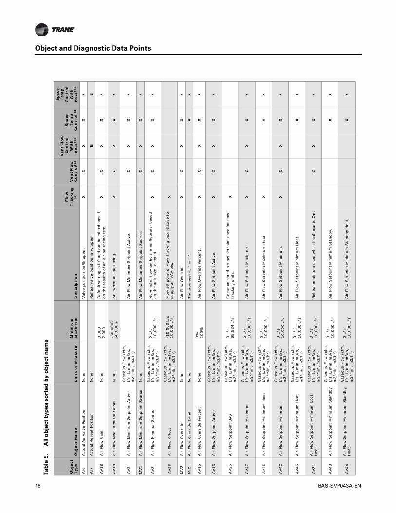
Tab
le 9
.A
ll o
bje
ct
typ
es s
ort
ed
by
ob
ject
na
me
Ob
ject
Ty
pe
Ob
ject
Nam
eU
nit
s o
f M
easu
reM
inim
um
Max
imu
mD
escr
ipti
on
Flow
Tr
acki
ng
(a)
Ven
t Flo
w
Con
trol
(a)
Ven
t Flo
w
Co
ntr
ol
Wit
h
Hea
t(a)
Sp
ace
Tem
p
Co
ntr
ol(
a)
Sp
ace
Tem
p
Con
tro
l W
ith
H
eat(
a)
AI6
Act
ual A
ir V
alve
Pos
ition
Non
e
Valv
e po
sitio
n on
% o
pen.
XX
XX
X
AI7
Act
ual R
ehea
t Po
sitio
nN
one
Re
heat
val
ve p
ositi
on in
% o
pen.
BB
AV18
Air F
low
Gai
nN
one
0.00
02.
000
Def
ault
sett
ing
is 1
.0 a
nd c
an b
e ed
ited
base
d on
the
res
ults
of
an a
ir b
alan
cing
tes
t.X
XX
XX
AV19
Air
Flo
w M
easu
rem
ent
Off
set
Non
e-5
0.00
0%50
.000
%Set
whe
n ai
r ba
lanc
ing.
XX
XX
X
AV2
Air F
low
Min
imum
Set
poin
t Act
ive
Gas
eous
Flo
w (
cfm
, L/
s, L
/min
, m
3/s,
m
3/m
in,
m3/
hr)
Air F
low
Min
imum
Set
poin
t Act
ive.
XX
XX
MV1
Air F
low
Min
imum
Set
poin
t Sou
rce
Non
e
Air F
low
Min
imum
Set
poin
t Sou
rce.
XX
XX
AV8
Air F
low
Nom
inal
Sta
tus
Gas
eous
Flo
w (
cfm
, L/
s, L
/min
, m
3/s,
m
3/m
in,
m3/
hr)
0 L/
s10
,000
L/s
Nom
inal
airflo
w s
et b
y th
e co
nfig
urat
or b
ased
on
the
uni
t si
ze s
elec
ted.
XX
XX
X
AV26
Air F
low
Off
set
Gas
eous
Flo
w (
cfm
, L/
s, L
/min
, m
3/s,
m
3/m
in,
m3/
hr)
-10,
000
L/s
10,0
00 L
/sFl
ow s
et p
oint
of F
low
Tra
ckin
g bo
x re
lativ
e to
su
pply
air V
AV b
ox.
X
MV2
Air
Flo
w O
verr
ide
Non
e
Air F
low
Ove
rrid
e.X
XX
XX
MI2
Air
Flo
w O
verr
ide
Loca
lN
one
Th
umbw
heel
at
* or
**.
XX
AV15
Air
Flo
w O
verr
ide
Perc
ent
Non
e0% 10
0%Air F
low
Ove
rrid
e Pe
rcen
t.X
XX
XX
AV13
Air F
low
Set
poin
t Act
ive
Gas
eous
Flo
w (
cfm
, L/
s, L
/min
, m
3/s,
m
3/m
in,
m3/
hr)
Air F
low
Set
poin
t Act
ive.
XX
XX
X
AV25
Air F
low
Set
poin
t BAS
Gas
eous
Flo
w (
cfm
, L/
s, L
/min
, m
3/s,
m
3/m
in,
m3/
hr)
0 L/
s65
,534
L/s
Com
mun
icat
ed a
irflo
w s
etpo
int
used
for
flo
w
trac
king
uni
ts.
X
AV47
Air F
low
Set
poin
t M
axim
umG
aseo
us F
low
(cf
m,
L/s,
L/m
in,
m3/
s,
m3/
min
, m
3/hr
)
0 L/
s10
,000
L/s
Air F
low
Set
poin
t M
axim
um.
XX
XX
X
AV46
Air F
low
Set
poin
t M
axim
um H
eat
Gas
eous
Flo
w (
cfm
, L/
s, L
/min
, m
3/s,
m
3/m
in,
m3/
hr)
0 L/
s10
,000
L/s
Air F
low
Set
poin
t M
axim
um H
eat.
XX
X
AV42
Air F
low
Set
poin
t M
inim
um
Gas
eous
Flo
w (
cfm
, L/
s, L
/min
, m
3/s,
m
3/m
in,
m3/
hr)
0 L/
s10
,000
L/s
Air F
low
Set
poin
t M
inim
um.
XX
XX
X
AV45
Air F
low
Set
poin
t M
inim
um H
eat
Gas
eous
Flo
w (
cfm
, L/
s, L
/min
, m
3/s,
m
3/m
in,
m3/
hr)
0 L/
s10
,000
L/s
Air F
low
Set
poin
t M
inim
um H
eat.
XX
AV31
Air F
low
Set
poin
t M
inim
um L
ocal
H
eat
Gas
eous
Flo
w (
cfm
, L/
s, L
/min
, m
3/s,
m
3/m
in,
m3/
hr)
0 L/
s10
,000
L/s
Rehe
at m
inim
um u
sed
whe
n lo
cal h
eat
is O
n.
XX
XX
AV43
Air F
low
Set
poin
t M
inim
um S
tand
byG
aseo
us F
low
(cf
m,
L/s,
L/m
in,
m3/
s,
m3/
min
, m
3/hr
)
0 L/
s10
,000
L/s
Air F
low
Set
poin
t M
inim
um S
tand
by.
XX
AV44
Air F
low
Set
poin
t M
inim
um S
tand
by
Hea
t
Gas
eous
Flo
w (
cfm
, L/
s, L
/min
, m
3/s,
m
3/m
in,
m3/
hr)
0 L/
s10
,000
L/s
Air F
low
Set
poin
t M
inim
um S
tand
by H
eat.
XX
18 BAS-SVP043A-EN

Object and Diagnostic Data Points
AI9
Air V
alve
1 S
trok
e Ti
me
Non
e
60,0
00
mill
isec
onds
570,
000
mill
isec
onds
Air v
alve
str
oke
time
in m
illis
econ
ds (
100-
mill
isec
ond
reso
lutio
n).
XX
XX
X
BV1
Air
Val
ve P
ositi
on C
ontr
olN
one
Air V
alve
Pos
ition
Con
trol
:•
0 =
pre
ssur
e in
depe
nden
t co
ntro
l.•
1 =
pos
ition
con
trol
/ p
ress
ure
depe
nden
t.X
XX
XX
AO
1Air V
alve
Pos
ition
Sta
tus
Non
e
Valu
e of
AO
is t
he r
eque
sted
% o
pen.
No
te:
Refe
r to
Act
ual A
ir V
alve
Pos
ition
.X
XX
XX
BV8
Aut
o Cal
ibra
teN
one
Au
to C
alib
rate
.X
XX
XX
AV10
Aut
o Cha
ngeo
ver
Poin
tTe
mpe
ratu
re (
°F o
r °C
)10
°C (
50°F
)10
0°C (
212°
FAu
to C
hang
eove
r Po
int.
XX
AV75
Aut
o Com
mis
sion
ing
Air V
alve
100
Non
e
Perc
ent
air
valv
e po
sitio
n at
100
% flo
w.
XX
XX
X
AV74
Aut
o Com
mis
sion
ing
Air V
alve
40
Non
e
Perc
ent
air
valv
e po
sitio
n at
40%
flo
w.
XX
XX
X
BV11
Aut
o Com
mis
sion
ing
Com
man
dN
one
U
sed
to e
limin
ate
auto
com
mis
sion
ing.
XX
XX
X
AV76
Aut
o Com
mis
sion
ing
Dis
char
ge A
ir
Tem
pera
ture
Fan
Off
Tem
pera
ture
(°F
or
°C)
D
isch
arge
air t
emp
is r
ecor
ded
during
aut
o co
mm
issi
onin
g.D
D
AV77
Aut
o Com
mis
sion
ing
Dis
char
ge A
ir
Tem
pera
ture
Fan
On
Tem
pera
ture
(°F
or
°C)
Au
to C
omm
issi
onin
g D
isch
arge
Air
Tem
pera
ture
with
the
fan
Off.
DD
AV78
Aut
o Com
mis
sion
ing
Dis
char
ge A
ir
Tem
pera
ture
Reh
eat
Tem
pera
ture
(°F
or
°C)
Au
to C
omm
issi
onin
g D
isch
arge
Air
Tem
pera
ture
with
reh
eat tu
rned
on.
Ava
ilabl
e if
conf
igur
ed w
ith lo
cal h
eat.
AF
AV80
Aut
o Com
mis
sion
ing
Dis
char
ge A
ir
Tem
pera
ture
Sta
ge 1
Hea
tTe
mpe
ratu
re (
°F o
r °C
)
Auto
Com
mis
sion
ing
Dis
char
ge A
ir
Tem
pera
ture
with
1 s
tage
of
heat
on.
CC
AV81
Aut
o Com
mis
sion
ing
Dis
char
ge A
ir
Tem
pera
ture
Sta
ge 2
Hea
tTe
mpe
ratu
re (
°F o
r °C
)
Auto
Com
mis
sion
ing
Dis
char
ge A
ir
Tem
pera
ture
with
2 s
tage
s of
hea
t on
. Av
aila
ble
with
mul
tiple
sta
ges
of lo
cal h
eat.
AA
AV82
Aut
o Com
mis
sion
ing
Dis
char
ge A
ir
Tem
pera
ture
Sta
ge 3
Hea
tTe
mpe
ratu
re (
°F o
r °C
)
Auto
Com
mis
sion
ing
Dis
char
ge A
ir
Tem
pera
ture
with
3 s
tage
s of
hea
t on
. Av
aila
ble
whe
n co
nfig
ured
with
thre
e st
ages
of
loca
l hea
t.
AA
AV79
Aut
o Com
mis
sion
ing
Dis
char
ge A
ir
Tem
pera
ture
Wat
er V
alve
Tem
pera
ture
(°F
or
°C)
Au
to C
omm
issi
onin
g D
isch
arge
Air
Tem
pera
ture
with
wat
er v
alve
ope
n.B
B
MV8
Aut
o Com
mis
sion
ing
Sta
teN
one
Au
to C
omm
issi
onin
g Sta
te.
XX
XX
X
AV67
Aux
iliar
y H
eat
Con
trol
Req
uest
Non
e0% 10
0%Au
xilia
ry h
eat
enab
le -
reh
eat
enab
le.
XX
AV66
Cab
inet
Sty
leN
one
0 255
Cab
inet
Sty
le.
XX
XX
X
AV83
Coo
l Typ
eN
one
0 255
Coo
l Typ
e.X
XX
XX
AV87
Coo
ling
Set
poin
t H
igh
Lim
itTe
mpe
ratu
re (
°F o
r °C
)
4.44
°C (
20.1
2°F)
46.1
1°C
(114
.99°
F)H
igh
limit
for
cool
ing
setp
oint
.X
X
AV88
Coo
ling
Set
poin
t Lo
w L
imit
Tem
pera
ture
(°F
or
°C)
4.44
°C (
20.1
2°F)
46.1
1°C
(114
.99°
F)Lo
w li
mit
for
cool
ing
setp
oint
.X
X
Tab
le 9
.A
ll o
bje
ct
typ
es s
ort
ed
by
ob
ject
na
me (
co
nti
nu
ed
)
Ob
ject
Ty
pe
Ob
ject
Nam
eU
nit
s o
f M
easu
reM
inim
um
Max
imu
mD
escr
ipti
on
Flow
Tr
acki
ng
(a)
Ven
t Flo
w
Con
trol
(a)
Ven
t Flo
w
Co
ntr
ol
Wit
h
Hea
t(a)
Sp
ace
Tem
p
Co
ntr
ol(
a)
Sp
ace
Tem
p
Con
tro
l W
ith
H
eat(
a)
BAS-SVP043A-EN 19

Object and Diagnostic Data Points
BV2
Def
ault
Sup
ply
Air T
empe
ratu
re M
ode
Non
e
Def
ault
Sup
ply
Air T
empe
ratu
re M
ode:
•1
= h
ot (
heat
ing)
.•
0 =
col
d (c
oolin
g) [
defa
ult]
.•
Leav
es fac
tory
at
defa
ult.
XX
BV3
Dia
gnos
tic:
Air F
low
Ove
rrid
e Lo
cal
Non
e
Loca
l thu
mbw
heel
is in
ove
rrid
e po
sitio
n of
* o
r **
.X
X
BV7
Dia
gnos
tic:
Flow
Sen
sor
Cal
ibra
tion
Failu
reN
one
D
iagn
ostic
: Fl
ow S
enso
r Cal
ibra
tion
Failu
re.
XX
XX
X
BV13
Dia
gnos
tic:
Flow
Sen
sor
Failu
reN
one
Pr
essu
re s
enso
r fa
ulte
d di
agno
stic
.X
XX
XX
BV10
Dia
gnos
tic:
Free
ze P
rote
ctio
nN
one
Fr
eeze
pro
tect
ion
diag
nost
ic (
on
ly f
or
vent
ilatio
n flo
w c
ontr
ol u
nits
).B
BV12
Dia
gnos
tic:
Hig
h Air F
low
Non
e
Flow
sen
sor r
eadi
ng to
o hi
gh D
iagn
ostic
Flo
w >
12
0% o
f no
min
al f
low
.X
XX
XX
BV9
Dia
gnos
tic:
Low
Prim
ary
Air F
low
Non
e
Low
prim
ary
airf
low
dia
gnos
tic (
on
ly f
or
elec
tric
hea
t).
Exis
ts if
con
figur
ed o
nly
with
lo
cal e
lect
ric
heat
.A
A
AV20
Dis
char
ge A
ir F
low
Gas
eous
Flo
w (
cfm
, L/
s, L
/min
, m
3/s,
m
3/m
in,
m3/
hr)
Pres
sure
sen
sor
1 va
lue
conv
erte
d to
flo
w.
XX
XX
X
AV39
Dis
char
ge A
ir T
emp
Set
poin
t Lo
cal
Tem
pera
ture
(°F
or
°C)
-7.2
2°C (
19.0
0°F)
21.1
1°C 6
9.99
°F)
•O
nly
for
VFC
con
figur
atio
n.•
Dis
char
ge a
ir t
emp
setp
oint
fro
m w
ired
se
nsor
.X
X
AI4
Dis
char
ge A
ir T
empe
ratu
reTe
mpe
ratu
re (
°F o
r °C
)-4
0°C (
-40°
F)10
0°C (
212°
F)D
isch
arge
air t
empe
ratu
re s
enso
r w
ire
to t
he
cont
rolle
r.X
XX
X
AV16
Dis
char
ge A
ir T
empe
ratu
re S
etpo
int
BAS
Tem
pera
ture
(°F
or
°C)
-7.2
2°C (
19.0
0°F)
21.1
1°C (
69.9
9°F)
•O
nly
for
VFC
con
figur
atio
n.•
Dis
char
ge a
ir te
mp
setp
oint
com
mun
icat
ed
from
BAS.
•Fa
ctor
y de
faul
t is
Out
of S
ervi
ce. T
o us
e th
is
poin
t, p
ut I
nto
Ser
vice
.
XX
AV53
ECM
Fan
Cor
rect
ion
Fact
or
Non
e0 65
,535
ECM
Fan
Cor
rect
ion
Fact
or. E
xist
s if
conf
igur
ed
only
with
ECM
fan
.A
A
AV56
ECM
Fan
Flo
w S
etpo
int
Gas
eous
Flo
w (
cfm
, L/
s, L
/min
, m
3/s,
m
3/m
in,
m3/
hr)
0 L/
s10
,000
L/s
PWM
% =
(EC
M fa
n flo
w s
etpo
int -
min
) /
(max
-
min
). E
xist
s if
conf
igur
ed o
nly
with
ECM
fan
.A
A
AV54
ECM
Fan
Max
imum
Flo
wG
aseo
us F
low
(cf
m,
L/s,
L/m
in,
m3/
s,
m3/
min
, m
3/hr
)
0 L/
s10
,000
L/s
PWM
% =
(EC
M fa
n flo
w s
etpo
int -
min
) /
(max
-
min
). E
xist
s if
conf
igur
ed o
nly
with
ECM
fan.
Va
lue
is fac
tory
set
.A
A
AV55
ECM
Fan
Min
imum
Flo
wG
aseo
us F
low
(cf
m,
L/s,
L/m
in,
m3/
s,
m3/
min
, m
3/hr
)
0 L/
s10
,000
L/s
PWM
% =
(EC
M fa
n flo
w s
etpo
int -
min
) /
(max
-
min
). E
xist
s if
conf
igur
ed o
nly
with
ECM
fan.
Va
lue
is fac
tory
set
.A
A
BO
1EC
M F
an O
utpu
t N
one
EC
M f
an o
n/of
f. W
ith E
CM
fan
pow
ered
onl
y.A
A
MV9
Emer
genc
y O
verr
ide
BAS
Non
eEm
erge
ncy
over
ride
req
uest
.X
XX
XX
AV70
Fan
Air F
low
Rat
ing
Gas
eous
Flo
w (
cfm
, L/
s, L
/min
, m
3/s,
m
3/m
in,
m3/
hr)
0 L/
s4,
000
L/s
•N
eede
d to
bal
ance
ECM
fan
.•
Set
in t
he f
acto
ry.
•Ex
ists
if c
onfig
ured
onl
y w
ith m
odul
atin
g he
at.
AA
BO
2Fa
n O
utpu
tN
one
Fa
n on
/off
(st
anda
rd m
otor
).D
D
Tab
le 9
.A
ll o
bje
ct
typ
es s
ort
ed
by
ob
ject
na
me (
co
nti
nu
ed
)
Ob
ject
Ty
pe
Ob
ject
Nam
eU
nit
s o
f M
easu
reM
inim
um
Max
imu
mD
escr
ipti
on
Flow
Tr
acki
ng
(a)
Ven
t Flo
w
Con
trol
(a)
Ven
t Flo
w
Co
ntr
ol
Wit
h
Hea
t(a)
Sp
ace
Tem
p
Co
ntr
ol(
a)
Sp
ace
Tem
p
Con
tro
l W
ith
H
eat(
a)
20 BAS-SVP043A-EN

Object and Diagnostic Data Points
AV68
Fan
Ove
rrid
e BAS
Non
e0% 10
1%
Use
d to
ove
rrid
e fa
n sp
eed.
•0%
= f
an O
ff.•
100%
= O
n/O
ff f
an o
verr
ide
on,
ECM
at
100%
.•
1%–9
9% =
ECM
fan
at th
e sp
ecifi
ed %
, On/
Off
fan
is O
N.
•10
1% a
nd g
reat
er is
def
ault
(no
over
ride
).
DD
MV4
Hea
t Coo
l Mod
e Re
ques
tN
one
H
eat
Coo
l Mod
e Re
ques
t co
mm
unic
ated
by
BAS.
XX
XX
X
MV5
Hea
t Coo
l Mod
e Sta
tus
Non
e
Hea
t Coo
l Mod
e Sta
tus.
XX
XX
X
BO
7H
eat
Out
put
1N
one
H
eat s
tage
1. D
oes
not e
xist
if o
nly
mod
ulat
ing
heat
is c
onfig
ured
.A
A
BO
6H
eat
Out
put
2N
one
H
eat
stag
e 2.
Exi
sts
whe
n co
nfig
ured
with
a
tota
l of
2 st
ages
of
loca
l and
rem
ote
heat
.A
A
BO
5H
eat
Out
put
3N
one
H
eat
stag
e 3.
Exi
sts
whe
n co
nfig
ured
with
a
tota
l of
2 st
ages
of
loca
l and
rem
ote
heat
.A
A
AV12
Hea
t O
utpu
t Sec
onda
ry S
tatu
sN
one
Perc
ent o
utpu
t val
ue (n
ot th
e sa
me
as c
apac
ity
in a
ll ca
ses)
.•
For
mod
ulat
ing
this
is t
he v
alve
pos
ition
.•
For
PWM
, th
is is
the
cap
acity
.•
For Sta
ged,
are
the
disc
rete
val
ues
for ea
ch
stag
e (f
or e
xam
ple,
2 s
tage
is 0
%,
50%
, 10
0% o
r 3
stag
e is
0%
, 33%
, 66%
, 100
%).
XX
AV89
Hea
ting
Set
poin
t H
igh
Lim
itTe
mpe
ratu
re (
°F o
r °C
)
4.44
°C (
20.1
2°F)
46.1
1°C
(114
.99°
F)H
igh
limit
for
heat
ing
setp
oint
.X
X
AV90
Hea
ting
Set
poin
t Lo
w L
imit
Tem
pera
ture
(°F
or
°C)
4.44
°C (
20.1
2°F)
46.1
1°C
(114
.99°
F)Lo
w li
mit
for
heat
ing
setp
oint
.X
X
MV12
Man
ual T
est
Seq
uenc
eN
one
M
anua
l Tes
t Seq
uenc
e nu
mbe
r.X
XX
XX
AI1
0M
inim
um A
ctua
tor
Tim
e N
one
100
mill
isec
onds
1,00
0 m
illis
econ
ds
•Air v
alve
min
imum
act
uato
r tim
e 10
0-m
illis
econ
d in
crem
ents
.•
Min
imum
500
mill
isec
onds
.X
XX
XX
BI1
Occ
upan
cy I
nput
Non
e
Occ
upan
cy s
enso
r.X
XX
X
MV6
Occ
upan
cy R
eque
stN
one
O
ccup
ancy
Req
uest
com
mun
icat
ed b
y BAS
.X
XX
X
MV7
Occ
upan
cy S
tatu
sN
one
O
ccup
ancy
Sta
tus.
XX
XX
AV33
Occ
upie
d Byp
ass
Tim
eN
one
0 m
inut
es24
0 m
inut
es
The
num
ber
of m
inut
es t
he u
nit
will
sta
y in
oc
cupi
ed b
ypas
s af
ter
initi
ated
by
time
over
ride
but
ton.
XX
XX
AV30
Occ
upie
d O
ffse
tTe
mpe
ratu
re D
elta
(°
F or
°C)
4.44
°C (
20.1
2°F)
46.1
1°C
(114
.99°
F)Set
poin
t of
fset
use
d du
ring
occ
upie
d m
ode.
XX
AV21
Out
door
Air
Low
Lim
itTe
mpe
ratu
re (
°F o
r °C
)-6
.66°
C (
20.1
2°F)
7.22
°C (
44.9
9°F)
VFC
fre
eze
prot
ectio
n.X
AV57
Para
llel F
an F
low
Ena
ble
Poin
tG
aseo
us F
low
(cf
m,
L/s,
L/m
in,
m3/
s,
m3/
min
, m
3/hr
)
0 L/
s10
,000
L/s
Para
llel F
an F
low
Ena
ble
Poin
t. E
xist
s if
conf
igur
ed a
s a
para
llel f
an p
ower
ed b
ox.
AA
AV58
Para
llel F
an T
emp
Enab
le P
oint
Tem
pera
ture
Del
ta
(°F
or °
C)
0°C (
32F)
4.44
° (3
9.99
°F)C
Para
llel F
an T
emp
Enab
le P
oint
. Ex
ists
if
conf
igur
ed a
s a
para
llel f
an p
ower
ed b
ox.
AA
Tab
le 9
.A
ll o
bje
ct
typ
es s
ort
ed
by
ob
ject
na
me (
co
nti
nu
ed
)
Ob
ject
Ty
pe
Ob
ject
Nam
eU
nit
s o
f M
easu
reM
inim
um
Max
imu
mD
escr
ipti
on
Flow
Tr
acki
ng
(a)
Ven
t Flo
w
Con
trol
(a)
Ven
t Flo
w
Co
ntr
ol
Wit
h
Hea
t(a)
Sp
ace
Tem
p
Co
ntr
ol(
a)
Sp
ace
Tem
p
Con
tro
l W
ith
H
eat(
a)
BAS-SVP043A-EN 21

Object and Diagnostic Data Points
AV52
PD M
ode
Min
Air
Val
ve P
ositi
onN
one
0.0%
100.
0%M
inim
um a
ir v
alve
pos
ition
in p
erce
nt w
hen
usin
g pr
essu
re d
epen
dent
con
trol
.X
XX
XX
AV84
Preh
eat
Type
Non
e0 25
5Pr
ehea
t Ty
pe.
XX
XX
X
AI3
Pres
sure
1G
aseo
us P
ress
ure
(in
H2O
, in
Hg,
mm
H2O
, m
m H
g, P
a, k
Pa)
0 pa
scal
s49
8 pa
scal
s
•Pr
essu
re a
cros
s th
e flo
w r
ing.
•12
0% fl
ow in
dica
tes
2 in
H2O
(49
8 pa
scal
s)
acro
ss flo
w r
ing.
XX
XX
X
BV6
Pres
sure
Dep
ende
nt M
ode
Rehe
at
Enab
leN
one
Pr
essu
re D
epen
dent
Mod
e Re
heat
Ena
ble.
XX
AV69
Pres
sure
Sen
sor
Cal
ibra
tion
Off
set
Gas
eous
Pre
ssur
e (i
n H
2O, i
n H
g, m
m H
2O,
mm
Hg,
Pa,
kPa
)
•Pr
essu
re r
eadi
ng w
ith a
ir d
ampe
r O
ff a
nd
fan
Off
(Pr
essu
re s
enso
r ca
libra
tion
- ze
ro
read
ing)
.•
This
val
ue is
sav
ed d
urin
g ca
libra
tion
and
subt
ract
ed o
ff s
ubse
quen
t re
adin
gs.
•If
not
with
in v
alid
ran
ge,
a flo
w s
enso
r ca
libra
tion
fails
dia
gnos
tic is
set
.
XX
XX
X
AV9
Rehe
at E
nabl
e Po
int
Tem
pera
ture
(°F
or
°C)
10°C
(50
°F)
100°
C (
212°
F)Re
heat
Ena
ble
Poin
t.X
X
BV5
Rehe
at P
rior
ityN
one
Re
heat
prior
ity o
f lo
cal a
nd r
emot
e he
at.
A
AV85
Rehe
at T
ype
Non
e0 25
5Re
heat
Typ
e.X
XX
XX
AV50
Spa
ce C
O2
Con
cent
ratio
n Act
ive
Non
e0
ppm
5,00
0 pp
mSpa
ce C
O2
conc
entr
atio
n us
ed b
y al
gorith
m.
XX
AV22
Spa
ce C
O2
Con
cent
ratio
n BAS
Non
e0
ppm
5,00
0 pp
m
Spa
ce C
O2 co
ncen
trat
ion
com
mun
icat
ed fr
om
the
BAS in
ppm
. If u
sed,
the
syst
em w
ill w
rite
to
thi
s po
int
once
eve
ry 1
5 m
inut
es.
Oth
erw
ise,
the
con
trol
ler
will
put
the
poi
nt
into
fau
lt st
atus
. Fa
ctor
y de
faul
t is
Out
of
Ser
vice
. To
use
thi
s po
int,
put
Int
o Ser
vice
.
XX
AI8
Spa
ce C
O2
Con
cent
ratio
n Lo
cal
Non
e0
ppm
5,00
0 pp
mSpa
ce C
O2
conc
entr
atio
n in
ppm
.X
X
AV40
Spa
ce C
O2
Lim
itN
one
0 pp
m2,
000
ppm
Poin
t w
here
CO
2 de
man
d ve
ntila
tion
ends
in
ppm
.X
X
AV41
Spa
ce C
O2
Low
Lim
itN
one
0 pp
m2,
000
ppm
Poin
t whe
re C
O2
dem
and
vent
ilatio
n be
gins
in
ppm
.X
X
AV37
Spa
ce T
emp
Set
poin
t D
efau
ltTe
mpe
ratu
re (
°F o
r °C
)
4.44
°C (
20.1
2°F)
46.1
1°C
(114
.99°
F)
Def
ault
spac
e te
mpe
ratu
re s
etpo
int
stor
ed in
th
e co
ntro
ller
and
set
by s
ervi
ce t
ool.
XX
AV59
Spa
ce T
empe
ratu
re A
ctiv
eTe
mpe
ratu
re (
°F o
r °C
)-1
5°C (
5°F)
50°C
(12
2°F)
Spa
ce t
empe
ratu
re b
eing
use
d by
alg
orith
m.
XX
AV14
Spa
ce T
empe
ratu
re B
AS
Tem
pera
ture
(°F
or
°C)
-15°
C (
5°F)
50°C
(12
2°F)
Spa
ce te
mpe
ratu
re c
omm
unic
ated
from
BAS
. If
use
d, t
he T
race
r SC w
ill w
rite
to
this
poi
nt
once
eve
ry 1
5 m
inut
es, b
ut O
NLY
if th
is p
oint
is
put
into
Ser
vice
. If
the
poi
nt is
in s
ervi
ce,
but
not
writt
en t
o ev
ery
15 m
inut
es t
he
cont
rolle
r w
ill p
ut t
he p
oint
into
fau
lt st
atus
. Fa
ctor
y de
faul
t is
Out
of Ser
vice
. To
use
thi
s po
int,
put
Int
o Ser
vice
.
XX
AI1
Spa
ce T
empe
ratu
re L
ocal
Tem
pera
ture
(°F
or
°C)
15°C
(59
°F)
50°C
(12
2°F)
Tem
pera
ture
sen
sor
in t
he s
pace
.X
X
Tab
le 9
.A
ll o
bje
ct
typ
es s
ort
ed
by
ob
ject
na
me (
co
nti
nu
ed
)
Ob
ject
Ty
pe
Ob
ject
Nam
eU
nit
s o
f M
easu
reM
inim
um
Max
imu
mD
escr
ipti
on
Flow
Tr
acki
ng
(a)
Ven
t Flo
w
Con
trol
(a)
Ven
t Flo
w
Co
ntr
ol
Wit
h
Hea
t(a)
Sp
ace
Tem
p
Co
ntr
ol(
a)
Sp
ace
Tem
p
Con
tro
l W
ith
H
eat(
a)
22 BAS-SVP043A-EN

Object and Diagnostic Data Points
AV28
Spa
ce T
empe
ratu
re S
etpo
int
Act
ive
Tem
pera
ture
(°F
or
°C)
-5.6
°C (
21.9
2°F)
56.1
°C (
132.
98°F
)Spa
ce t
empe
ratu
re s
etpo
int
bein
g us
ed b
y al
gori
thm
.X
X
AV27
Spa
ce T
empe
ratu
re S
etpo
int
BAS
Tem
pera
ture
(°F
or
°C)
-10°
C (
14°F
)35
°C (
95°F
)
Com
mun
icat
ed s
etpo
int.
Fac
tory
def
ault
is
Out
of Ser
vice
. To
use
thi
s po
int,
put
Int
o Ser
vice
. If
use
d w
ith a
Tra
cer
SC, th
e SC w
ill
plac
e th
e po
int
In S
ervi
ce d
urin
g in
stal
latio
n.
XX
AI2
Spa
ce T
empe
ratu
re S
etpo
int
Loca
lTe
mpe
ratu
re (
°F o
r °C
)10
°C (
50°F
)29
.4°C
(84
.92°
F0Zo
ne s
enso
r th
umbw
heel
.X
X
AV34
Sta
ndby
Off
set
Tem
pera
ture
Del
ta
(°F
or °
C)
4.44
°C (
20.1
2°F)
46.1
1°C
(114
.99°
F)
Set
poin
t of
fset
use
d du
ring
occ
upie
d st
andb
y m
ode.
XX
AV60
Sup
ply
Air T
empe
ratu
re A
ctiv
eTe
mpe
ratu
re (
°F o
r °C
)-4
0°C (
-40°
F)10
0°C (
212°
F)Sup
ply
Air T
empe
ratu
re A
ctiv
e.B
XX
AV29
Sup
ply
Air T
empe
ratu
re B
AS
Tem
pera
ture
(°F
or
°C)
0°C (
32°F
)10
0°C (
212°
F)
Sup
ply
air
tem
pera
ture
com
mun
icat
ed fro
m
BAS.
Fac
tory
def
ault
is O
ut o
f Ser
vice
. To
use
this
poi
nt,
put
Into
Ser
vice
. If
use
d w
ith a
Tr
acer
SC,
the
SC w
ill p
lace
the
poi
nt I
n Ser
vice
dur
ing
inst
alla
tion.
BX
X
AI5
Sup
ply
Air T
empe
ratu
re L
ocal
Tem
pera
ture
(°F
or
°C)
-40°
C (
-40°
F)10
0°C (
212°
F)Sup
ply
air
tem
pera
ture
sen
sor
wired
to
the
cont
rolle
r.B
XX
AO
2Sup
ply
Fan
Spe
edN
one
Sup
ply
fan
in p
erce
nt.
For
sing
le-s
peed
fan
s,
0% =
Off,
100
% =
On.
DD
AV86
Sup
ply
Fan
Type
Non
e0 25
5Sup
ply
Fan
Type
.X
XX
XX
MI1
Tim
ed O
verr
ide
Sta
tus
Non
e
Tim
ed o
verr
ide
butt
on p
ush
dete
cted
.X
X
AV23
Uno
ccup
ied
Coo
ling
Set
poin
tTe
mpe
ratu
re (
°F o
r °C
)
4.44
°C (
20.1
2°F)
46.1
1°C
(114
.99°
F)U
nocc
upie
d Coo
ling
Set
poin
t.X
X
AV24
Uno
ccup
ied
Hea
ting
Set
poin
tTe
mpe
ratu
re (
°F o
r °C
)
4.44
°C (
20.1
2°F)
46.1
1°C
(114
.99°
F)U
nocc
upie
d H
eatin
g Set
poin
t.X
X
AV36
Vent
ilatio
n Ra
tioN
one
0%
–100
%.P
erce
ntag
e in
dica
tes
the
requ
ired
ra
tio o
r ou
tdoo
r ai
r-to
-prim
ary
air
need
ed t
o m
eet
zone
ven
tilat
ion
requ
irem
ents
.X
X
AV51
Vent
ilatio
n Ra
tio L
imit
BAS
Non
e0% 10
0%
Vent
ilatio
n Rat
io L
imit
from
the
BAS in
pe
rcen
t. F
acto
ry d
efau
lt is
Out
of S
ervi
ce. T
o us
e th
is p
oint
, pu
t In
to S
ervi
ce. If
use
d w
ith
a Tr
acer
SC,
the
SC w
ill p
lace
the
poi
nt I
n Ser
vice
dur
ing
inst
alla
tion.
XX
AV35
Vent
ilatio
n Set
poin
t Act
ive
Gas
eous
Flo
w (
cfm
, L/
s, L
/min
, m
3/s,
m
3/m
in,
m3/
hr)
Ve
ntila
tion
Set
poin
t Act
ive.
XX
AV48
Vent
ilatio
n Set
poin
t BAS
Gas
eous
Flo
w (
cfm
, L/
s, L
/min
, m
3/s,
m
3/m
in,
m3/
hr)
0 L/
s10
,000
L/s
This
is li
mite
d by
Ven
tilat
ion
Set
poin
t Loc
al a
nd
Vent
ilatio
n Set
poin
t Sta
ndby
. Fa
ctor
y de
faul
t is
Out
of
Ser
vice
. To
use
thi
s po
int,
put
Int
o Ser
vice
.
XX
XX
AV38
Vent
ilatio
n Set
poin
t Lo
cal
Gas
eous
Flo
w (
cfm
, L/
s, L
/min
, m
3/s,
m
3/m
in,
m3/
hr)
0 L/
s10
,000
L/s
Vent
ilatio
n Set
poin
t Lo
cal.
XX
XX
Tab
le 9
.A
ll o
bje
ct
typ
es s
ort
ed
by
ob
ject
na
me (
co
nti
nu
ed
)
Ob
ject
Ty
pe
Ob
ject
Nam
eU
nit
s o
f M
easu
reM
inim
um
Max
imu
mD
escr
ipti
on
Flow
Tr
acki
ng
(a)
Ven
t Flo
w
Con
trol
(a)
Ven
t Flo
w
Co
ntr
ol
Wit
h
Hea
t(a)
Sp
ace
Tem
p
Co
ntr
ol(
a)
Sp
ace
Tem
p
Con
tro
l W
ith
H
eat(
a)
BAS-SVP043A-EN 23

Object and Diagnostic Data Points
AV49
Vent
ilatio
n Sta
ndby
Set
poin
tG
aseo
us F
low
(cf
m,
L/s,
L/m
in,
m3/
s,
m3/
min
, m
3/hr
)
0 L/
s10
,000
L/s
Vent
ilatio
n Sta
ndby
Set
poin
t.X
X
AI1
1W
ater
Val
ve M
axim
um S
trok
e Ti
me
Non
e60
mill
isec
onds
240
mill
isec
onds
This
is u
sed
for
rem
ote
or lo
cal m
odul
atin
g w
ater
hea
t va
lve.
In
mill
isec
onds
.E
AI1
2W
ater
Val
ve M
inim
um A
ctua
tor
Tim
eN
one
100
mill
isec
onds
1,00
0 m
illis
econ
dsW
ater
val
ve m
inim
um a
ctua
tor
time
100-
mill
isec
ond
incr
emen
ts.
E
MV3
Wat
er V
alve
Ove
rrid
eN
one
W
ater
Val
ve O
verr
ide.
BB
AO
3H
eatin
g Va
lve
Com
man
d N
one
Mod
ulat
ing
rehe
at v
alve
. Thi
s is
the
requ
este
d po
sitio
n in
per
cent
.N
ote
:Re
fer
to H
eatin
g Cap
acity
Sec
onda
ry
for
actu
al w
ater
val
ve p
ositi
on.
FE
(a)L
EGEN
D:
A=
Dep
ende
nt o
n co
nfig
urat
ion
(ref
er t
o po
int
desc
ript
ion
for
mor
e in
form
atio
n)B=
If
conf
igur
ed w
ith h
ot w
ater
val
ve.
C=
If
conf
igur
ed w
ith e
lect
ric
heat
.D
= I
f co
nfig
ure
as fan
pow
ered
.E=
If
conf
igur
ed w
ith m
odul
atin
g ho
t w
ater
.X=
Exi
sts.
Tab
le 9
.A
ll o
bje
ct
typ
es s
ort
ed
by
ob
ject
na
me (
co
nti
nu
ed
)
Ob
ject
Ty
pe
Ob
ject
Nam
eU
nit
s o
f M
easu
reM
inim
um
Max
imu
mD
escr
ipti
on
Flow
Tr
acki
ng
(a)
Ven
t Flo
w
Con
trol
(a)
Ven
t Flo
w
Co
ntr
ol
Wit
h
Hea
t(a)
Sp
ace
Tem
p
Co
ntr
ol(
a)
Sp
ace
Tem
p
Con
tro
l W
ith
H
eat(
a)
24 BAS-SVP043A-EN

VAV Alarming
VAV Alarming
Tracer BACnet VAV controllers have four (4) analog inputs and six (6) binary values used for communicating alarms to the system.
Additional Resources
Use the following as additional resources:
• Tracer BACnet Terminator Installation Instructions (X39641151-01)
• BACnet Best Practices and Troubleshooting Guide (BAS-SVX51-EN)
• Tracer TU Service Tool Getting Started Guide (BAS-SVU047-EN)
• Tracer TU Online Help
• Tracer® UC400 Programmable Controller Installation, Operation, and Maintenance Manual (VAV-SVX07-EN)
• Symbio® 210 Programmable Variable-Air-Volume (VAV) Box Controller Installation, Operation, and Maintenance Manual (BAS-SVX084*-EN)
Note: For further assistance, contact your local Trane sales office.
Table 10. Alarm objects
Object Type Object Name Description
Notification Class
AI1 Space Temperature Local Space temperature sensor has failed or is out of range. 2
AI2 Space Temperature Setpoint Local Space temperature setpoint (thumbwheel) has failed or is out of range. 2
AI4 Discharge Air Temperature Discharge air temperature sensor has failed or is out of range. 2
AI5 Supply Air Temperature Local Supply air temperature sensor has failed or is out of range. 2
BV3 Diagnostic: Air Flow Override Local
Thumbwheel is presently at * or ** position, which overrides the airflow:• 0 = Inactive• 1 = Active
4
BV7 Diagnostic: Flow Sensor Calibration Failure • 0 = Inactive• 1 = Active 2
BV9 Diagnostic: Low Primary Air FlowElectric Heat Only:• 0 = Inactive• 1 = Active
4
BV10 Diagnostic: Freeze Protection Only for ventilation flow control units. 4
BV12 Diagnostic: High Air Flow • 0 = Inactive• 1 = Active (when flow>120% of nominal flow. 3
BV13 Diagnostic: Flow Sensor FailurePressure Sensor Fault:• 0 = Inactive• 1 = Active
2
BAS-SVP043A-EN 25

Notes
Notes
26 BAS-SVP043A-EN

Notes
BAS-SVP043A-EN 27

©2021 Trane
Trane has a policy of continuous product and product data improvement and reserves the right to change design and specifications without notice. We are committed to using environmentally conscious print practices.
Trane - by Trane Technologies (NYSE: TT), a global climate innovator - creates comfortable, energy efficient indoor environments for commercial and residential applications. For more information, please visit trane.com or tranetechnologies.com.
BAS-SVP043A-EN 15 Jun 2021(NEW)