Integrated Science Instrument Module Status€¦ · · 2016-12-27The ISIM system consists of: –...
23
Integrated Science Instrument Module Status Matt Greenhouse JWST Project Office NASA Goddard Space Flight Center 17 July 2013 1 Presentation to: NAC Astrophysics Subcommittee: Distribution Unlimited 17 July 2013
Transcript of Integrated Science Instrument Module Status€¦ · · 2016-12-27The ISIM system consists of: –...
Integrated Science Instrument Module Status
Matt Greenhouse JWST Project Office NASA Goddard Space Flight Center 17 July 2013
1 Presentation to: NAC Astrophysics Subcommittee: Distribution Unlimited 17 July 2013
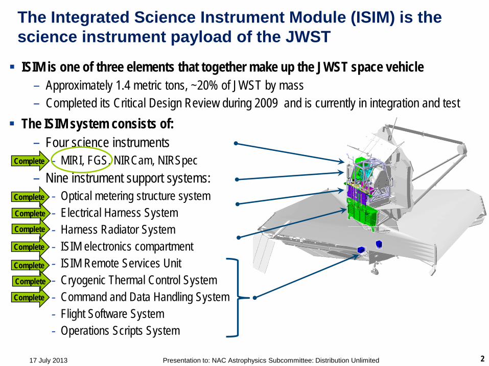
The Integrated Science Instrument Module (ISIM) is the science instrument payload of the JWST
The ISIM system consists of: – Four science instruments
- MIRI, FGS, NIRCam, NIRSpec – Nine instrument support systems:
- Optical metering structure system - Electrical Harness System - Harness Radiator System - ISIM electronics compartment - ISIM Remote Services Unit - Cryogenic Thermal Control System - Command and Data Handling System - Flight Software System - Operations Scripts System
ISIM is one of three elements that together make up the JWST space vehicle
– Approximately 1.4 metric tons, ~20% of JWST by mass – Completed its Critical Design Review during 2009 and is currently in integration and test
2 Presentation to: NAC Astrophysics Subcommittee: Distribution Unlimited
Complete
Complete
Complete
Complete
Complete
Complete
Complete
Complete
17 July 2013

NIRCam will provide the deepest near-infrared images ever and will identify primeval galaxy targets for the NIRSpec
Developed by the University of Arizona with Lockheed Martin ATC – Operating wavelength: 0.6 – 5.0 microns – Spectral resolution: 4, 10, 100 (filters + grism), coronagraph – Field of view: 2.2 x 4.4 arc minutes – Angular resolution (1 pixel): 32 mas < 2.3 microns, 65 mas > 2.4 microns – Detector type: HgCdTe, 2048 x 2048 pixel format, 10 detectors, 40 K passive cooling – Refractive optics, Beryllium structure
Supports telescope wavefront sensing
Flight NIRCam Module A
3 Presentation to: NAC Astrophysics Subcommittee: Distribution Unlimited
Flight NIRCam Module B
17 July 2013
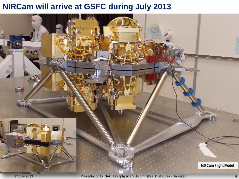
NIRCam will arrive at GSFC during July 2013
4 Presentation to: NAC Astrophysics Subcommittee: Distribution Unlimited
NIRCam Flight Model
17 July 2013
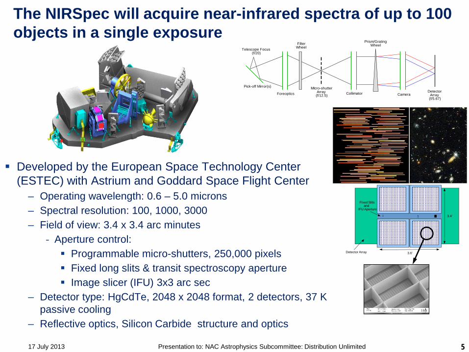
The NIRSpec will acquire near-infrared spectra of up to 100 objects in a single exposure
Developed by the European Space Technology Center (ESTEC) with Astrium and Goddard Space Flight Center
– Operating wavelength: 0.6 – 5.0 microns – Spectral resolution: 100, 1000, 3000 – Field of view: 3.4 x 3.4 arc minutes
- Aperture control: Programmable micro-shutters, 250,000 pixels Fixed long slits & transit spectroscopy aperture Image slicer (IFU) 3x3 arc sec
– Detector type: HgCdTe, 2048 x 2048 format, 2 detectors, 37 K passive cooling
– Reflective optics, Silicon Carbide structure and optics
MIcro-shutterArray
(f/12.5) Collimator
Prism/GratingWheel
CameraDetector
Array(f/5.67)
Telescope Focus (f/20)
Foreoptics
FilterWheel
Pick-off Mirror(s)
3.6’
3.4’
Detector Array
Fixed Slits and
IFU Aperture
5 Presentation to: NAC Astrophysics Subcommittee: Distribution Unlimited 17 July 2013

Aperture control: 250,000 programmable micro-shutters System flight qualified and delivered to ESA June 2010
Human Hair 90 um Dia.
203 x 463 mas shutter pixel clear aperture, 267 x 528 mas pitch, 4 x 171 x 365 array
Flight MSA
6 Presentation to: NAC Astrophysics Subcommittee: Distribution Unlimited 17 July 2013

NIRSpec delivery is expected during September 2013
7 Presentation to: NAC Astrophysics Subcommittee: Distribution Unlimited
FM2 test Jan 2013
17 July 2013

The MIRI instrument will characterize circumstellar debris disks, extra-solar planets, and the evolutionary state of high redshift galaxies
Developed by a consortium of 10 European countries and NASA/JPL – Operating wavelength: 5 - 29 microns – Spectral resolution: 5, 100, 2000 – Broad-band imagery: 1.9 x 1.4 arc minutes FOV – Coronagraphic imagery – Spectroscopy:
- R100 long slit spectroscopy 5 x 0.2 arc sec - R2000 spectroscopy 3.5 x 3.5 and 7 x 7 arc sec FOV integral field units
– Detector type: Si:As, 1024 x 1024 pixel format, 3 detectors, 7 K cryo-cooler – Reflective optics, Aluminum structure and optics
Flight Model
8 Presentation to: NAC Astrophysics Subcommittee: Distribution Unlimited
Flight MIRI on test fixture
17 July 2013

MIRI was delivered to ISIM I&T during May 2012
9 Presentation to: NAC Astrophysics Subcommittee: Distribution Unlimited
5.6 micron point source
4.9 – 11.8 micron IFU 5.6 microns broad-band 11.4 – 28.8 micron IFU
MIRI flight model
17 July 2013

Developed by the Canadian Space Agency with ComDev – Broad-band guider (0.6 – 5 microns) – Field of view: 2.3 x 2.3 arc minutes – Science imagery:
- Slitless spectroscopic imagery (grism) R ~ 150, 0.8 – 2.25 microns optimized for Ly alpha galaxy surveys R ~ 700, 0.7 – 2.5 microns optimized for exoplanet transit spectroscopy
- Sparse aperture interferometric imaging (7 aperture NRM) 3.8, 4.3, and 4.8 microns – Angular resolution (1 pixel): 68 mas – Detector type: HgCdTe, 2048 x 2048 pixel format, 3 detectors – Reflective optics, Aluminum structure and optics
The FGS-Guider and -NIRISS provide telescope pointing control imagery & slitless spectroscopy for Ly-α galaxy surveys and extra-solar planet transits
FGS Flight Model
10 Presentation to: NAC Astrophysics Subcommittee: Distribution Unlimited 17 July 2013
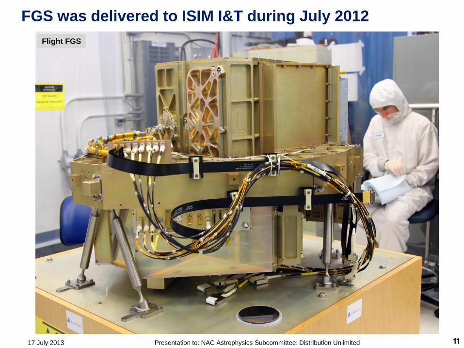
FGS was delivered to ISIM I&T during July 2012
Flight FGS
11 Presentation to: NAC Astrophysics Subcommittee: Distribution Unlimited 17 July 2013

The ISIM structure has been qualified for ambient and cryogenic strength, cryogenic dimensional repeatability and distortion
Carbon-fiber/cyanate-ester composite material – Primary launch-load bearing structure (warm launch) – High precision optical requirements
Key dimensional requirements for thermal cycling (300 to 30 K) verified to better than 25 micron precision
– Repeatability: 80 microns – Distortion: 500 microns
Cryogenic and ambient strength proof test and modal survey completed
12 Presentation to: NAC Astrophysics Subcommittee: Distribution Unlimited
ISIM flight structure cryogenic photogrammetry testing
ISIM flight structure ambient temp strength testing
17 July 2013
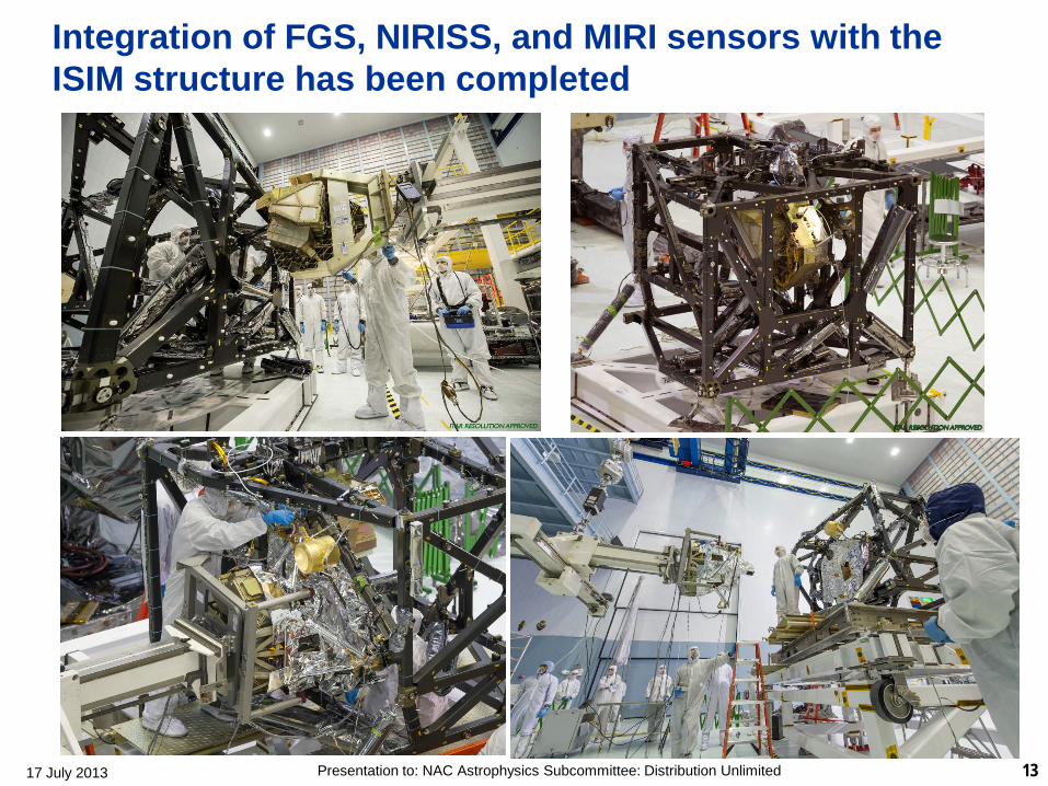
Integration of FGS, NIRISS, and MIRI sensors with the ISIM structure has been completed
13 Presentation to: NAC Astrophysics Subcommittee: Distribution Unlimited 17 July 2013
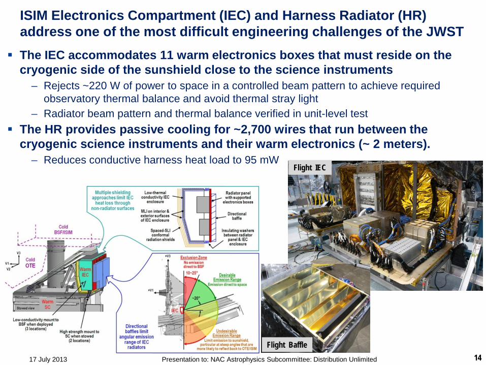
ISIM Electronics Compartment (IEC) and Harness Radiator (HR) address one of the most difficult engineering challenges of the JWST
The IEC accommodates 11 warm electronics boxes that must reside on the cryogenic side of the sunshield close to the science instruments
– Rejects ~220 W of power to space in a controlled beam pattern to achieve required observatory thermal balance and avoid thermal stray light
– Radiator beam pattern and thermal balance verified in unit-level test The HR provides passive cooling for ~2,700 wires that run between the
cryogenic science instruments and their warm electronics (~ 2 meters). – Reduces conductive harness heat load to 95 mW
14 Presentation to: NAC Astrophysics Subcommittee: Distribution Unlimited 17 July 2013
Flight Baffle
Flight IEC
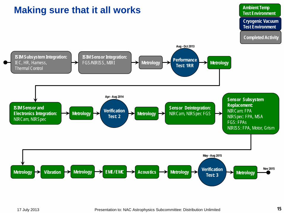
Making sure that it all works
17 July 2013 15 Presentation to: NAC Astrophysics Subcommittee: Distribution Unlimited
Metrology Metrology
Metrology Metrology EMI / EMC Metrology
Metrology Metrology
Verification Test: 3
Verification Test: 2
Performance Test: 1RR
ISIM Subsystem Integration: IEC, HR, Harness, Thermal Control
ISIM Sensor Integration: FGS/NIRISS, MIRI
ISIM Sensor and Electronics Integration: NIRCam, NIRSpec
Sensor Subsystem Replacement: NIRCam: FPA NIRSpec: FPA, MSA FGS: FPAs NIRISS: FPA, Motor, Grism
Sensor Deintegration: NIRCam, NIRSpec FGS
Acoustics Vibration Metrology
Ambient Temp Test Environment Cryogenic Vacuum Test Environment
Completed Activity Aug - Oct 2013
May - Aug 2015
Apr - Aug 2014
Nov 2015
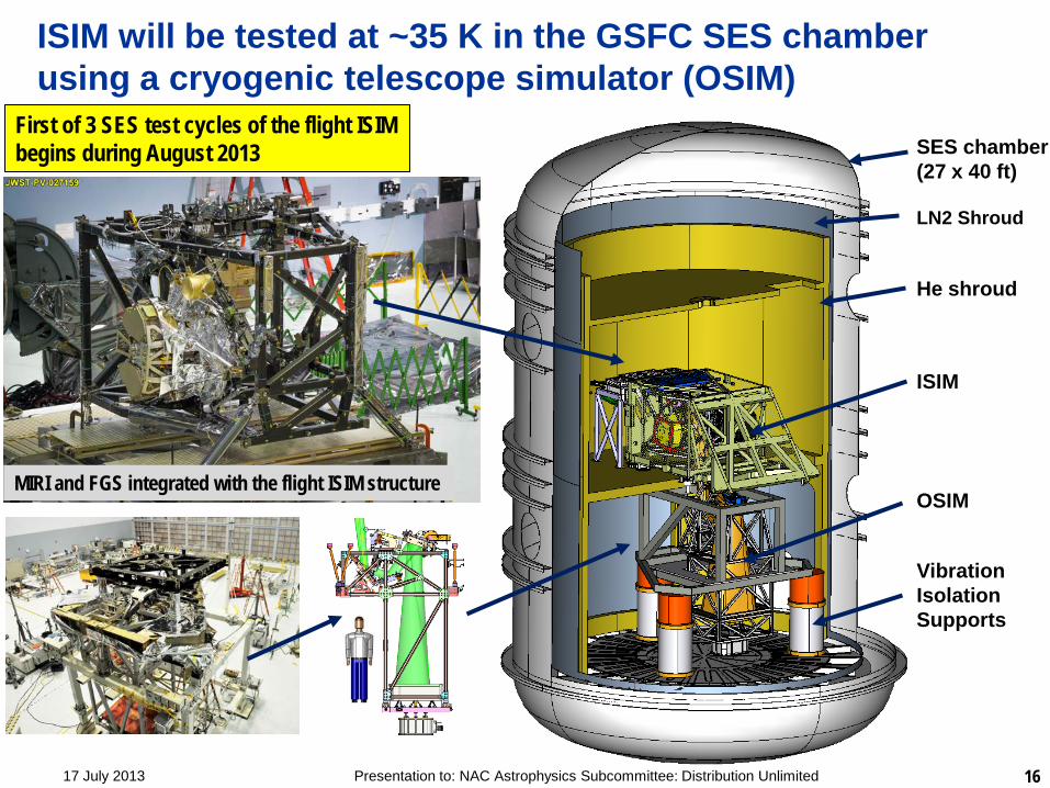
ISIM will be tested at ~35 K in the GSFC SES chamber using a cryogenic telescope simulator (OSIM)
SES chamber (27 x 40 ft) LN2 Shroud He shroud ISIM OSIM Vibration Isolation Supports
16 Presentation to: NAC Astrophysics Subcommittee: Distribution Unlimited
First of 3 SES test cycles of the flight ISIM begins during August 2013
MIRI and FGS integrated with the flight ISIM structure
17 July 2013

17 17 July 2013 Presentation to: NAC Astrophysics Subcommittee: Distribution Unlimited
Test Items – Test Exposure of Items in SES Testing prior to Cryo-Vacuum TestC
ycle
sIte
ms
in T
est
Test
s
He Shroud Acceptance Test (-03)
Chamber Certification Test
(-01)
ISIM Structure Cryoset Test
ISIM Structure Cryo-Proof Test OSIM Cryo-Cal Test 1 ISIM Element Cryo-
Vacuum Tests(3 tests planned)
He Shroud (-03) He Shroud (-01)Lower GESHAUpper GESHAGISITPPhotogrammetryFabreeka VIS*MIRI MLI ExpmntBolometers
He Shroud (-01)Lower GESHAUpper GESHAGISITP / MATFPhotogrammetryFabreeka VIS*MIRI MLI ExpmntBolometersFlight StructureIATF
He Shroud (-01)Lower GESHAUpper GESHAGISITPPhotogrammetryFabreeka VIS*RadiometerFlight StructureIATF
He Shroud (-01)Lower GESHAUpper GESHAGISITP / MATFPhotogrammetryFabreeka VISOSIM BaffleOSIMOSIM ShroudBIASIF/Shroud Support Frame
He Shroud (-01)Lower/Upper GESHA, GISITP/ MATFFabreeka VISFlight StructureIATFOSIM OSIM ShroudSIF/Shroud Support FrameScience Instruments (SI)#Flight HarnessFlight Heat StrapsMIRI Cryo-Cooler#MCASIF & Interfaces to FrameSurrogate TMSIEC w/ Shroud /LN2 PanelHarness RadiatorHR Shroud
1 cycle to 15KB/O to 70C
1 cycle to 15K1 cycle to 30KB/O to 50C
1 cycle to 39K1 cycle to 28KB/O to 40C
1 cycle to 28K 1 cycle to 30K (BIA)1 cycle of OSIM to 100K
CV1: 1 cycle to 43K
CV2: 1 cycle to 37K + 43K
CV3: 1 cycle to 37K + 43K
Not in Previous SES Tests
* - caveat; Fabreeka’s were not energized in these tests# - caveat; NIRSpec, NIRCam are not in CV1, and Cryo cColer CHA ETU used in CV 1 test.
Underlined items indicate flight articles
COMPLETE2008
COMPLETEMarch 2010
COMPLETEMay 2010
COMPLETENov 2010
OSIM Cryo-Cal Test 2
COMPLETEAug 2012
COMPLETEMay 2013
The upcoming ISIM CV-1RR test is the culmination of 5 years of test facility development for it
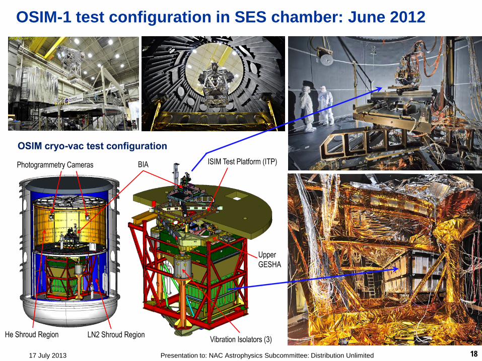
OSIM-1 test configuration in SES chamber: June 2012
18 Presentation to: NAC Astrophysics Subcommittee: Distribution Unlimited 17 July 2013

Sensor subsystem re-work proceeding on schedule Near-Infrared detectors
– Degradation of original flight detectors necessitates remanufacture
- Root cause determined and corrected; new design qualified through test
– Production of new units on schedule for replacement prior to ISIM CV-3; NIRCam units currently on schedule for replacement prior to CV-2
NIRSpec MSA – Flight unit out of spec due to damage
sustained during acoustic testing - Root cause of unexpected acoustic
susceptibility determined and corrected on flight spare unit which is in manufacturing Resiliency to flight acoustic loads proven
through test – Plan to install flight spare MSA prior to ISIM
CV-3
17 July 2013 19 Presentation to: NAC Astrophysics Subcommittee: Distribution Unlimited
New NIRCam 16 Mpix Flight FPA
MSA Q4-FT180 Acoustic Testing Proto-flight Level
Cycle 1
Cycle 2 Cycle 3 (in NIRSpec ETU)
Pre-Test
Learn more at: www.jwst.nasa.gov http://webbtelescope.org/webb_telescope/progress_report/
Watch the JWST being built at:
www.jwst.nasa.gov/webcam.html Read about JWST science mission objectives at:
http://www.jwst.nasa.gov/science.html http://www.stsci.edu/jwst/science/whitepapers/
Explore your science objectives with the JWST observing time estimator:
http://jwstetc.stsci.edu/etc/ Interact with the JWST Science Working Group:
http://www.jwst.nasa.gov/workinggroup.html 20 Presentation to: NAC Astrophysics Subcommittee: Distribution Unlimited 17 July 2013
Supplemental Slides
21 Presentation to: NAC Astrophysics Subcommittee: Distribution Unlimited 17 July 2013

The NIRISS includes an Aperture Masking Interferometry (AMI) mode that enables moderate contrast imagery at an inner working angle of λ/2D
NRM
Available in 3 broad-band filters: 3.8, 4.3, 4.8 um over which NIRISS is Nyquist sampled Yields 10-12 magnitudes of point source contrast over a 70-500 mas annulus NIRCam coronagraphy limited to an inner working angle of approximately 600 mas
Simulated companion above has contrast of 10 mag at a separation of 130 mas Equivalent to a 1-2 MJup planet at ~1 AU of a 50 Myr-old M0V dwarf at a distance of 10 pc from the Sun. Above simulation corresponds to approximately 3 hours of observing time
400 mas NIRCam IWA
NIRCam at 4.3μm with 6 λ/D occulter.
NIRISS AMI detection map
NIRISS & NIRCam IWA and contrast
22 Presentation to: NAC Astrophysics Subcommittee: Distribution Unlimited 17 July 2013

CV-1RR Objectives • Primary:
– Demonstrate that the test configuration, which includes large amounts of new GSE, is able to support the test requirements of the ISIM verification program (identify any necessary fixes to hardware before CV2)
– By dry-running critical test procedures, learn how to most efficiently formulate and execute them and to analyze the results (identify any necessary improvements to procedures before CV2)
– Demonstrate that the cryo-vacuum test setup provides adequate thermal control and stability through an entire cryogenic cycle (cool down, plateau at ISIM operating temperature, warm up) and supports the capability of performing a thermal balance test
– Demonstrate operation of the MIRI, FGS, and NIRISS (hereafter “SIs”)with ISIM systems at temperature (basic performance, timing, noise)
– Demonstrate the management of the hardware from a contamination control standpoint
– Demonstrate the viability of the test setup for performing optical testing in terms of the jitter environment and stray light backgrounds
– Explore the interaction of the OSIM and the SI’s such that pointing, fluxes, and exposures can be planned and configured efficiently for performing optical verification in subsequent tests
• Secondary:
– Verify the cryo-cooler 6.2K heat load. This will be done by measuring the heat load to the J-T cooler
– By dry-running optical tests, provide an initial confirmation of key optical performance parameters, such as the six degree-of-freedom alignment of the SI’s, retiring the very low risk of any fundamental metrology problem in the OSIM or SI buildup
– Take the opportunity to perform critical SI-level verifications for NIRISS (never before operated end-to-end in its current optical configuration) and MIRI (detector regression testing to close out the sensitivity non-compliance investigation)
– By dry-running tests, provide a firm basis for planning and estimating the required time for the verification tests of CV2&3
– Train all test personnel in the logistics of test execution (communications, decision processes, roles and responsibilities) and analysis
17 July 2013 Presentation to: NAC Astrophysics Subcommittee: Distribution Unlimited 23