Integrated Power, Cooling, and Rack Infrastructure for Critical Networks Increase Availability While...
51
Integrated Power, Cooling, and Rack Infrastructure for Critical Networks Increase Availability While Decreasing Your Total Cost of Ownership (TCO) REV 5: 5/5/2003 3:38 PM ™
-
date post
22-Dec-2015 -
Category
Documents
-
view
214 -
download
0
Transcript of Integrated Power, Cooling, and Rack Infrastructure for Critical Networks Increase Availability While...
Integrated Power, Cooling, and Rack Infrastructure for Critical
Networks
Increase Availability While Decreasing Your Total Cost of Ownership (TCO)
REV 5: 5/5/2003 3:38 PM
™

NCPI : Overview
Foundation for “High Availability”
Networks

What drives data center costs?• The concept of $/sqft is routinely used to describe
data center cost
• This suggests that area drives cost, which is false.
Per Sq Foot costs25%
Per Watt costs75%
PowerCoolingService
Engineering
SpaceImprovements
Racks

Benefit of compaction is not present without corresponding reduction in power
0%
20%
40%
60%
80%
100%
0 2 4 6 8 10 12 14 16 18 20
Compaction: KW Per Rack
To
tal
Co
st
of
Ow
ne
rsh
ip
If $$ were really driven by square feet
Reality: $$ are driven by Watts
• $/Watt costs dominate TCO• The concept of $/sqft suggests unrealistic TCO
improvements via compaction

Actual power draws in real data centers
0%
5%
10%
15%
20%
25%
30%
0.5 1.5 2.5 3.5 4.5 5.5 6.5 7.5 8.5 9.5 10.5 11.5 12.5 13.5 14.5 15.5
Per Rack Power - kW
% o
f E
nc
los
ure
s
2002 actual dataave = 1.5kW
Max blade server
Max1 Userver
Gartnerguidance
>90% of new data centerscapability

Powering high density racks
• Voltage, power, and connector requirements strongly suggest the use of 3-phase power distribution to the rack
• A 3-phase 20A power whip can provide 7.2kW per whip, with both 120V and 208V available at the same time
• Two or more of these whips can support extreme density

Power and Cooling infrastructure limits the area savings available from compaction
0
5
10
15
20
25
30
35
40
45
50
1 2 3 4 5 6 7 8 9 10 11 12 13 14 15 16 17 18 19 20
Compaction density: KW Per Rack
Are
a i
n s
qft
/ k
W
Area of IT equipment
Area of power and cooling infrastructure
Total area of IT equipment and infrastructure
Total area does not decrease
after about 5kW per
rack

Conclusion• It is challenging to cool isolated racks >6kW or groups
>4kW in conventional data centers
• Compaction without corresponding reduction in power consumption is ineffective and expensive
• A practical approach to density is to establish density limits
• 7.2 and 14.4 kW are natural per-rack density limit values due to branch circuit limits
• Where ultra high density is required, fully ducted cooling systems provide highest performance and predictability
More information on these subjects is available from APC White Papers at www.apcc.com

AgilityFact: Traditional approaches to increasing power and
cooling capacity can take up to a year or more to implement, slowing business response to market.
“I need a server.”
“I have a server.”
2 Days
“I need more capacity.” 400 Days
“I have more capacity.”
The Speed of Business is the Speed of the IT Response!

Traditional Approach (400 day)
Design Concept
Construction Design
Construction
Commissioning
Operation
Custom Parts, Applications and Services
“I need more capacity.”
“I have more capacity.”
Needs Assessment

• The Design Concept is built on standardized parts that can be scaled to meet the need?
• Construction Design incorporates a “Lego Block” approach of pre-engineered components?
• Construction is mainly done in a factory instead of on-site?
• Commissioning tests pre-integrated infrastructure systems.
What if……

A Quick Review: The Next Generation Data Center Design is…
• Modular
• Plug and Play
• Scalable
• Fault tolerant
• Portable
• Pre-engineered
• Module-based mistake-proof servicing
• Has Built-in management based on TCP IP standards
• Does not require raised floor

Solutions:Solutions: System Level System Level ChallengesChallenges
• Live system can be expanded at will.
• Drastically reduces one-time engineering.
• Collapses the Design-Specify-Purchase-Commission Cycle.
• Standardized, off-the-shelf, cost effective components.
• No services or integration “surprises.”
• Much of the field installation replaced by pre-assembly.
• Standardized documentation and operations.and operation

Link to Movie
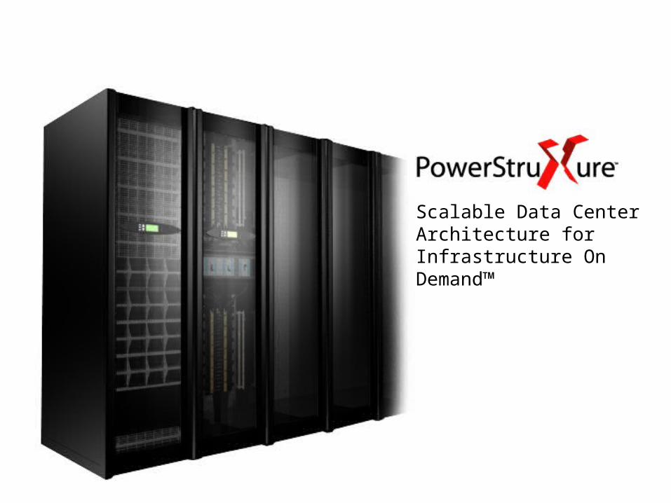
Scalable Data Center Architecture for Infrastructure On Demand™

Power for Closets and Computer Rooms
UPS Options Summary
1 Rack: Smart-UPS 1500
1 – 2 Racks: Smart-UPS 3000 (XL)
1 – 4 Racks: Smart-UPS 5000 (XL)
1 – 4 Racks: Symmetra RM 6kVA
1 – 10 Racks: Symmetra 12kVA

InfraStruXure Type A: 1-10

Data Center design

Type B

5 – 100 Racks
5 – 20 Racks: InfraStruXure 20kW frame
10 – 60 Racks: Symmetra PX 40kW frame
60 – 100 Racks: Symmetra PX 80kW frame

– 208V Nominal Input / Output (4-wire)– Double Conversion– Power factor corrected input– UP to 15 min Runtime (0.8 pf) with
internal batteries– 20kVA/kW N+1– Up to 4 XR Battery Frames may be
connected for extended runtimes– Input voltage range: 166 – 240VAC– Input frequency range: 40 – 70 Hz– Efficiency: >91.5% – Overload capability
• 125% overload: continuous via static bypass
• 150% for 30 seconds• 1000% 500ms: via static bypass
– Heat Dissipation = 6489 BTU/Hr (1.9kW)
InfraStruXure 20kW Specifications

10-60 Racks: SYPX40• 40kVA/40kW capacity in 10kVA/10kW power module
increments
– power factor corrected input
– fully rated inverter
• Power modules arranged in N+1 configuration
• Battery modules arranged in a parallel redundant configuration
• All modules are hot-swappable
• Housed in a 35.5” NetShelter VX enclosure
– footprint = 5.67sq ft
– rolls through 7’ door
• 125% continuous rated, user replaceable static switch
• XR frames available for longer runtime requirements

60-100 Racks: 80KW PDU w/Bypass
• Housed in the VX Wide Enclosure
– just 36” deep, not 42”
• Manual Maintenance Bypass
• Capable of 208V, 480V, and 600V input
• Contains a single 400A, (42) Position Panel board
– CTO option to include up to (4) 80A sub-feed breakers to rack mount Remote Distribution Panels (RDP)
• Additional CTO capabilities:
– Dual Feed (separate mains and bypass feed – bypass feed must be 208V)
– Load Test Port connection

Symmetra PX Product Design Benefits
Power View
Easy to read and navigate through menus and functions
Power Module
Provides the flexibility to scale power capacity and adds N+1 capability
Built-in Static Bypass Switch
Enables the UPS to transfer the load to utility power, without interruption, in case of heavy overload or faulty conditions
Redundant Intelligence Module
Acts as back-up for the Main Intelligence Module
Battery Module
Hot swappable for easy replacement by trained user
Symmetra PX

– Same XR Frame as Symmetra PX 40kW– Holds 8 battery modules– A fully populated battery enclosure will provide
an ISX-20kW with 45 minutes of runtime (0.8pf)– Weight: 2100 lbs fully loaded– Up to 4 XR Enclosures can be added
XR Battery Frame

Changing the way the world designs data centers…
On-Demand Architecture forNetwork-Critical Physical Infrastructure
InfraStruXureTM for Data Centers

InfraStruXure® Systems for Data Center
Scalable Cooling
Air removal solutions (shown) and in-row cooling solutions enhance scalability, and allow for quick deployment and adaptation for IT upgrades
Management Integration
Minimize implementation time by quickly integrating your new design into existing management system
Monitor Environmental Conditions
Enhance the system with environmental controls for earlier detection and faster problem resolution Available Options
Additional “add-on’s available, including
ATS/Generator, Security, Environmental, etc.
Rack Design
Vendor-neutral enclosure improves adaptability for diverse IT environment

Present the Solution
Standard Components
Allows you to customize solution, minimize human error, and lower Mean-Time-To-Repair
Integrated Cooling
Effectively capture the hot air where it is created and deliver cool air where it is required.
Integrated Power and Cable Distribution
Self contained power and data cable distribution eliminates the need for raised floor
Automatic Transfer Switch with Distribution Panel
Delivers redundant power by monitoring and controlling APC’s Standby Power Generator and ATS via the network
Standby Power Generator
Increase runtime requirements from minutes to days

Symmetra PX Options and Related Products
External Battery Enclosure Rack-based, scalable design for extended runtimes
PDU with System BypassConfigurable PDU in a rack- based design
Environmental Monitoring Identifies thermal problems before damage occurs
RemoteMonitoringMonitoring and performance trending of enterprise power and environmental infrastructure
APC Global Services A variety of product based and professional services
Symmetra PX

The cooling dilemma • 15kW of blade servers can be purchased today and
installed into a single rack.
• 11kW of 1U servers can be purchased today and installed into a single rack
• People will attempt to install this equipment (600W/sqft) in data centers where the industry average load is 1.4kW per rack (45W/sqft).

Don’t forget about availability
• Redundancy of cooling becomes more complex and
harder to predict at higher density
• The Air Conditioning System must be on UPS after
approximately 120W / sq ft (4kW/rack) because the IT
system will overheat during the generator startup delay
• These are difficult technical problems which make it very
difficult to reliably cross the 150W/sq ft barrier

More Problems: Dynamic Power Variation
• Most IT equipment draws virtually constant power independent of its computational load
• Early 1U servers were based on desktop technology and exhibited power that varied with function. This was the first significant exposure of the data center to dynamic power variation
• P4 Xeon and near term processors do not support power management.
• Enlightened customers and possibly public policy will dictate that processors manage power.
• Consequence: The data center of the future will need improved management tools to manage dynamic power variations without overload or malfunction.

High density answers that do work
• Careful hot-isle-cold-isle design
– Properly laid out racks
– Properly located returns over hot isles
– Eliminating raised floor bypass leakage
• Blanking panels
– Can reduce hotspot server intake air by up to 15 degrees
F (see APC white paper #44)
• Limit: 3-4 kW per rack

Cooling capability limitations of the raised floor
0
1
2
3
4
5
6
7
0 100 200 300 400 500 600 700 800 900 1000
Tile Airflow (CFM)
Rac
k P
ow
er (
KW
)
TypicalCapability
WithEffort
Extreme Impractical
Raised floor power capability
Practical Limit: 3-4 kW per rack if one tile used
Single tile per rack10 degree C rise

High density answers that do work
• Hot air scavenging systems
– Collect hot air at the point of generation
– Route directly to CRAC
– Snap-on retrofit
– Variable speed: as needed
– Dual Path Power and N+1
– Flexible, Movable
• Limit: 6-9 kW per rack

Wiring Closet Ventilation UnitAirflow Diagram
Wiring Closet Ventilation Unit pulls warm air from the room
Warm air is exhausted from IT equipment
Conditioned air from outside the room enters via intake vent
Warm, exhaust air Rises
Conditioned air supplied to IT equipment
Wiring Closet Ventilation Unit

InfraStruXure InRow SC Airflow
InfraStruXure InRow SC
Cool air from plenum space pulled
into unit via fans
Cool air is supplied to row or
room
Condenser air absorbs heat from
coil
Heat transferred to condenser coil
Heat rejected from room to plenum
space
Evaporator coil absorbs heat from air
Hot exhaust air from IT equipment pulled
into unit via fans
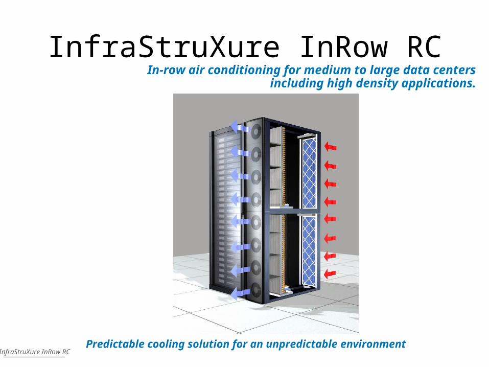
InfraStruXure InRow RC
InfraStruXure InRow RC
In-row air conditioning for medium to large data centers including high density applications.
Predictable cooling solution for an unpredictable environment

Rack Air Removal Unit
Rack Air Containment Airflow Diagram
• Fans of InRow cooling unit(s) distribute cool air to front of IT equipment
• Air passes through servers and absorbs heat
• Server exhaust air is prevented from escaping by rear containment
• All exhaust air is returned to InRow cooling unit(s)
• Proper airflow through the enclosure is ensured
Top Down View
Front
Rear
InRow Cooling
Unit
InRow Cooling
Unit
NetShelter SX Rack
Servers
Rear Containment
Front Containment

InRow RC Applications
• Hot Spots– Server consolidation– Compaction– Peak loads
Up to 30 kW chilled water
Capacity Planning Data center
expansion Rightsizing
High Density
Blade servers
NAS storage devices
1U servers
InfraStruXure InRow RC
• Dynamic loads– Batch processing – Grid computing

InRow RC Product Design Benefits
Air Filter
Removes airborne particles, protects coil
Top or Bottom Piping Connections
Variable Speed Hot Swappable Fans
Rightsizes cooling capacity, energy savings
Cooling Coil
Removes heat using chilled water
Condensate Management
Detects and removes condensation
Field Configurable 2-Way or 3-Way Valve Operation
Casters
Allows unit to move easily
InfraStruXure InRow RC
Dual A-B Power Inputs
Power redundancy and protection
Flow Meter
Measures water flow to facilitate determining unit kW output

InfraStruXureTM
InRow RC Value Proposition
Modular Solution that will adapt to the changing IT world.
•Availability–Predictable architecture–Mean Time To Recover
•Agility:– Standardized modules– Capacity on demand
• TCO:– Capacity per footprint– Rightsizing– Increase usable IT space
Changing the way the world designs data centers...
Predictable Cooling Solution for an Unpredictable environment

APC Solution Applied
VoIP and IP Telephony InfraStruXure Solution for Data Centers

Agility• Standardized Modules
– Raised Floor not required for cooling, reduces build out and eliminates space constraints
– Short lead time
• Capacity on Demand– Matches heat removal to the heat load– Enabling variable capacity without raised floor
dependency (no requirement for constant pressure)
• High Density Capable– Able to cool up to 60 kW in a single rack

InRow RC Summary
• Modular design increases agility by providing scaleable solutions to add cooling
as demand increases.
• Improved Energy Efficiency and Rightsizing reduces total cost of ownership.
• Placing the unit in the row of racks moves the source of cooling closer to the
heat load and minimizes air mixing thus improves availability.
• Up to 30 kW Capacity
Predictable cooling solution for an unpredictable environment
In-row air conditioning for medium to large data centers including high density applications.
InfraStruXure InRow RC

APC Management Solutions
Environmental Management System
Environmental Monitoring Unit
UPS Environmental Monitoring Card
Sensors
Because when something changes, you need to know.Management
Tools to remotely monitor and control, easily and economically.
UPS Network Management Cards
PowerChute Business Edition
Building Management Interface Card
Management Platform Integration
UPS enhancement cards
Network-Critical PhysicalInfrastructure
UPS Management
EnvironmentalManagement
Server Access
InfraStruXure Manager Appliance
Analog KVM Switches
Digital KVM Switches
Fliptop Monitor

InfraStruXure Manager Applications
Appliance with licenses for 25, 100 or 1000 nodes.Additional licenses available.
InfraStruXure Manager
• Data Center– Manage your
APC InfraStruXure
– Manage other APC devices on the network
Remote Branch Office Monitor remote
locations Give local personnel
read-only access
Distributed Network Monitor UPS &
other devices dispersed throughout the network
Network Closets Monitor locations
infrequently accessed

Manageable Devices within the InfraStruXure Management Architecture
InfraStruXure Manager
HTTP (Web)HTTP (Web)
SNMPSNMP
TelnetTelnet
EmailEmail
ModBus*ModBus*
APC Network APC Network Manageable Manageable
DeviceDevice
* UPS and cooling products only
Use of StandardsManage APC networked devices via existing network infrastructure.
Fault NotificationsEmail or SNMP notifications ensures crucial situations are dealt with in a timely manner.

Integrating InfraStruXure Management into Your Management Architecture
InfraStruXure Manager
Building Management System IntegrationManage critical building infrastructure from single system via modbus
Enterprise Management System IntegrationForward SNMP traps to your preferred management system
Manage Network-Critical Physical InfrastructureSimilar to server, storage and networking equipment.
Scalability Manage up to 1000 APC networked devices
Building Management
System
Enterprise Management
SystemNetwork Devices
Storage Devices
Server Devices
Server Manager
Storage Manager
Network Manager
Building PowerComfort Air
Building Environment
Power Devices
Rack Devices
Cooling Devices
InfraStruXure Manager

InfraStruXure ManagerCentralized management of your APC network-critical physical infrastructure.
Appliance with 25, 100 or 1000 nodes.
Additional licenses available.
Network-Critical Physical Infrastructure Management
Management

Left-hand barQuick link other
functions
Left-hand barQuick link other
functions
Main Status Screen:Overview of key
functions; UPS and card
Main Status Screen:Overview of key
functions; UPS and card
Browser AccessibleSaves installing software on the network management console.
Browser AccessibleSaves installing software on the network management console.
InfraStruXure Management Design BenefitsNetwork Management Card Screen Shot
InfraStruXure Management Design BenefitsNetwork Management Card Screen Shot