Integrated Module Heat Exchanger - Energy
26
NREL is a national laboratory of the U.S. Department of Energy, Office of Energy Efficiency and Renewable Energy, operated by the Alliance for Sustainable Energy, LLC. Integrated Module Heat Exchanger Kevin Bennion National Renewable Energy Laboratory May 15, 2012 Project ID #: APE047 This presentation does not contain any proprietary, confidential, or otherwise restricted information.
Transcript of Integrated Module Heat Exchanger - Energy
NREL is a national laboratory of the U.S. Department of Energy, Office of Energy Efficiency and Renewable Energy, operated by the Alliance for Sustainable Energy, LLC.
Integrated Module Heat Exchanger
Kevin Bennion National Renewable Energy Laboratory May 15, 2012
Project ID #: APE047
This presentation does not contain any proprietary, confidential, or otherwise restricted information.
2
Overview
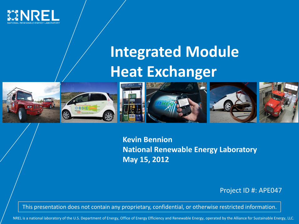
Project Start Date: FY 2012 Project End Date: FY 2013 Percent Complete: 30%
• Cost • Performance (Power Density)
Total Project Funding: DOE Share:$200K (FY12)
Funding Received in FY11: $0K Funding for FY12: $200K
Timeline
Budget
Barriers and Targets
• Interactions / collaborations – Sapa
• Project lead – National Renewable Energy Laboratory
Partners

3
Relevance/Objectives Problem: Cost, Volume, and Weight “Easy ways to increase output power are paralleling more silicon chips and/or step-up the die size to increase current capacity. But this strategy is unaffordable in terms of both increased chip cost and packaging space.” (2007) [1]
[1] Source: Yasui, H., et al., “Power Control Unit of High Power Hybrid System” – Denso and Toyota, SAE 2007-01-0271
Primary Concern: Heat “The most significant concern for increasing current is intensified heat dissipation in the silicon chips” (2007) [1]
Example A – Thermal Interface Material

4
Relevance/Objectives Problem: Cost, Volume, and Weight “Easy ways to increase output power are paralleling more silicon chips and/or step-up the die size to increase current capacity. But this strategy is unaffordable in terms of both increased chip cost and packaging space.” (2007) [1]
[1] Source: Yasui, H., et al., “Power Control Unit of High Power Hybrid System” – Denso and Toyota, SAE 2007-01-0271
Primary Concern: Heat “The most significant concern for increasing current is intensified heat dissipation in the silicon chips” (2007) [1]
Current Technology: Packaging and cooling developments have improved heat removal to increase power capability (power per die area)
Goal: Improve heat dissipation to improve power per die area (cost)
Example A – Thermal Interface Material Example B – Direct Cooled Baseplate Example C – Double Sided Cooling
Goal

5
Relevance/Objectives
Objective • Design and build a prototype heat exchanger module that improves
power per die area capability while enabling low cost and scalable heat exchanger technologies
Addresses Targets • Reduces cost by:
– Improving the power per die area by 100% – Introducing a modular and scalable thermal approach to reduce the
need for custom heat exchanger redesigns as applications scale in power
• Reduces weight by eliminating large heat exchanger cold plates • Maintains best-in-class power density capabilities
Uniqueness and Impacts • Technology is scalable to liquid-cooled systems and air-cooled systems • Research will improve liquid and air cooling of power electronics
[1] Credit: Mark Mihalic, NREL [2] Credit: Kevin Bennion, NREL
[2]
[1]

6
Milestones
Date Milestone or Go/No-Go Decision
September 2011 Internal Milestone: • Patent application submitted
February 2012 Go/No-Go: •Computer simulations of design match preliminary analysis
expectations and justify hardware prototype development
April 2012 Internal Milestone: • Finalize initial prototype design
September 2012 DOE Milestone: •Complete hardware tests on prototype • Submit report on design and test results
Go/No-Go: • Prototype heat exchanger hardware matches design
expectation • Proceed to second project phase to integrate with power
electronics package

7
Approach/Strategy
Project Metrics
Thermal Design Metrics
Component Level
Metrics
APEEM Targets
Desired Outputs
Cost
Power per Silicon Area IGBT Heat Flux 2x Heat Flux
Improvement
Cooling System Cost
Cooling Complexity
Lower-Cost Manufacturing
Methods
Less Aggressive Cooling Methods
Volume Power per Volume Total Heat Density (heat removed per package volume)
Maintain Best-In-Class Performance
APEEM – Advanced Power Electronics and Electric Motors IGBT – Insulated Gate Bipolar Transistor

8
Challenges
Eliminate fixed custom-designed, cold plate heat
exchangers
Integrate existing low-cost and scalable fabrication
methods
Scale research and development prototype to
address fabrication
Collaborate with industry partners
Integrating electronics package with cooling
requires robust and low thermal resistance interfaces
Collaborate with current APEEM efforts in bonded
interface material characterization
Support multiple power semiconductor packaging
methods
Consider single/double-sided cooling and alternative
interconnect methods
Approach/Strategy
All Images - Credit: Kevin Bennion, NREL
Strategy
9
Approach/Strategy
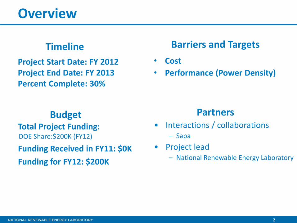
Prototype Hardware Development and Testing •Confirm performance metrics
2011
Oct
Nov
Dec
2012
Jan
Feb
Mar
Apr
May
Jun
Jul
Aug
Sep
Thermal Finite Element Analysis (FEA) Design Optimization •Thermal structure design •Material and geometry
selection
Cooling Technology Computational Fluid Dynamics (CFD) Analysis •Cooling surface enhancement design
(1) Go/
No Go
(2) Go/
No Go
In Progress
Legend
Complete
Model meets performance goals
Hardware meets performance goals
(Proceed to Phase II)
10
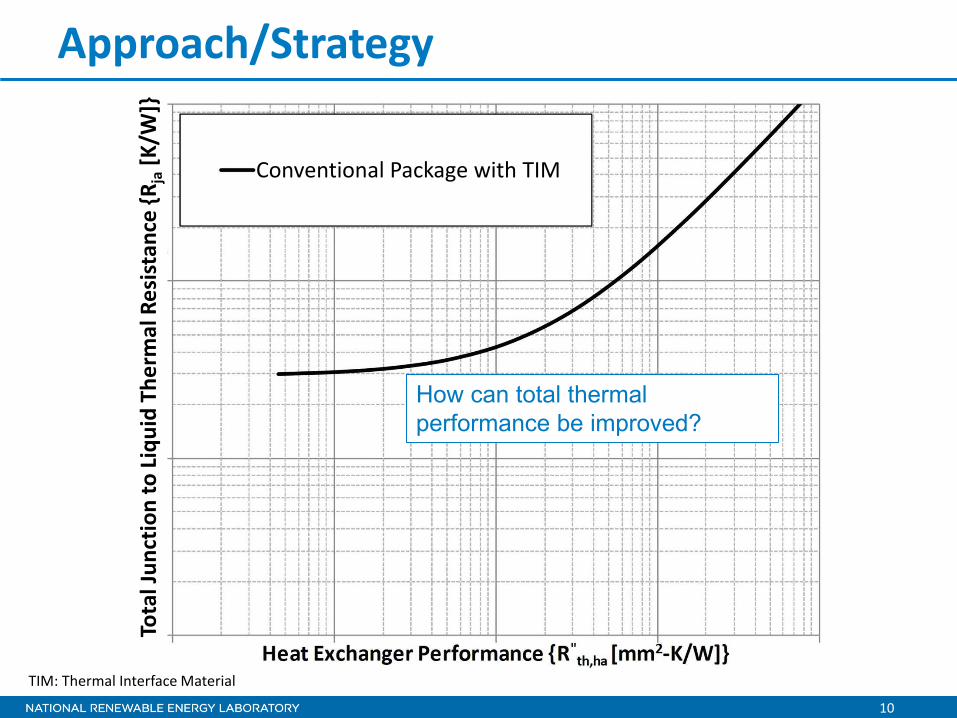
Approach/Strategy
How can total thermal performance be improved?
Conventional Package with TIM To
tal J
unct
ion
to Li
quid
The
rmal
Res
ista
nce
{Rja
[K/W
]}
TIM: Thermal Interface Material

11
Approach/Strategy
• Direct cooling of the package improves total thermal performance, especially when combined with improved cooling
Conventional Package with TIM
Direct-Cooled DBC
Tota
l Jun
ctio
n to
Liqu
id T
herm
al R
esis
tanc
e {R
ja [K
/W]}
DBC: Direct Bond Copper

12
Approach/Strategy
• Increased cooling area and heat-spreading methods support less aggressive cooling strategies
Conventional Package with TIM
Direct-Cooled DBC Increased Cooling Area
Tota
l Jun
ctio
n to
Liqu
id T
herm
al R
esis
tanc
e {R
ja [K
/W]}
13
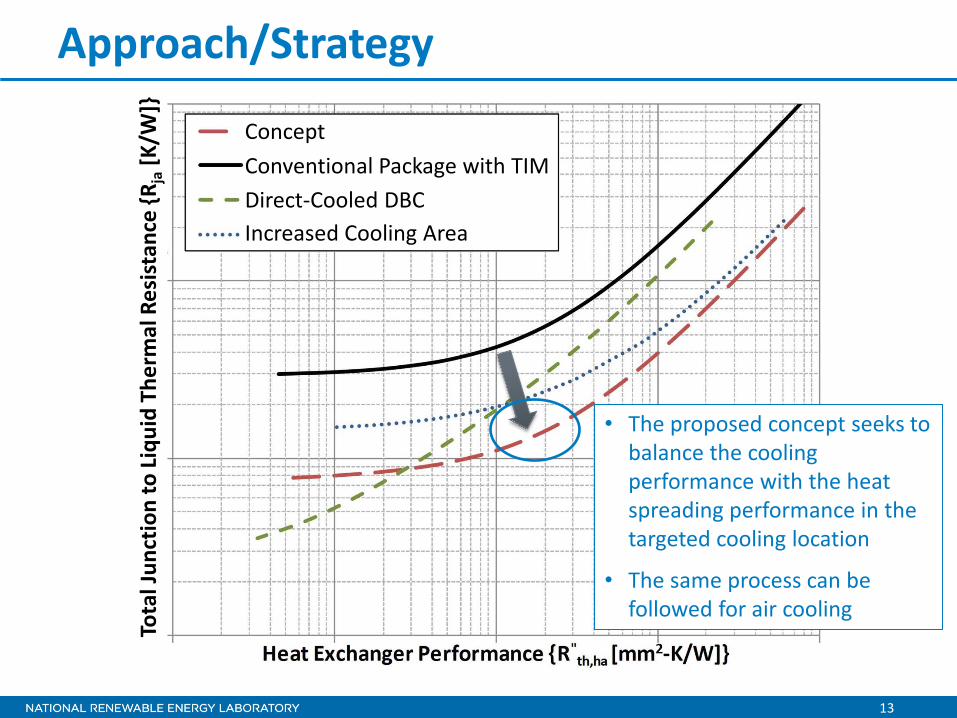
Approach/Strategy
• The proposed concept seeks to balance the cooling performance with the heat spreading performance in the targeted cooling location
• The same process can be followed for air cooling
Conventional Package with TIM Direct-Cooled DBC Increased Cooling Area
Concept To
tal J
unct
ion
to Li
quid
The
rmal
Res
ista
nce
{Rja
[K/W
]}

14
Technical Accomplishments and Progress
Thermal Stack Comparisons
Baseline A • 2008 Lexus LS 600H [1,2]
[1] K. Bennion and K. Kelly, Rapid Modeling of Power Electronics Thermal Management Technologies, NREL Milestone Report, Jul. 2009. [2] T. Burress, C. Coomer, S. Campbell, A. Wereszczak, J. Cunningham, L. Marlino, L. Seiber, and H.-T. Lin, Evaluation of the 2008 Lexus LS 600H Hybrid Synergy Drive System. Oak Ridge National Laboratory. ORNL/TM-2008/185, Jan. 2009.
Diode IGBT
Baseline “A” Comparison Heat Exchanger Location
(cooled on each side)
Provides direct comparison to high performance commercial integrated
package cooling design
Baseline B •Direct-Cooled Baseplate
Baseline “B” Comparison Heat Exchanger Location (single side shown)
IGBT Diode
Provides direct comparison to low thermal resistance package stack.
Selected baseline thermal stack configurations

15
Technical Accomplishments and Progress
Baseline Comparison Packages
Preliminary Designs
Targeted liquid cooling performance region from preliminary computational fluid dynamics (CFD) and analytical analysis
Designs exceed commercial baseline performance and direct-cooled baseplate layout
Compared performance of alternative designs at targeted cooling performance region

16
Technical Accomplishments and Progress Compared designs relative to baseline packages (heat density versus IGBT heat flux) • Design C1 shows best performance but has cost concerns • Design A2 shows good performance across design goals
Heat Density = Heat Rejection/Package Volume

17
Compared designs relative to baseline packages (footprint heat flux versus IGBT heat flux)
Technical Accomplishments and Progress
Footprint Heat Flux = Heat Rejection/Base Footprint Area

18
Technical Accomplishments and Progress
Design A2
Performed parametric design study around the selected design point (Design A2) • A significant jump to a better operating region was not found within the design constraints • Proceeding with Design A2
Heat Density = Heat Rejection/Package Volume
19
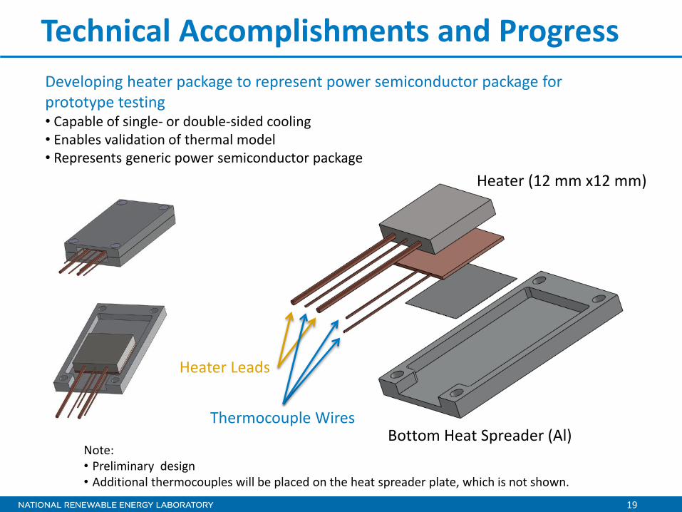
Developing heater package to represent power semiconductor package for prototype testing • Capable of single- or double-sided cooling • Enables validation of thermal model • Represents generic power semiconductor package
Technical Accomplishments and Progress
Heater (12 mm x12 mm)
Bottom Heat Spreader (Al) Thermocouple Wires
Heater Leads
Note: • Preliminary design • Additional thermocouples will be placed on the heat spreader plate, which is not shown.

20
Developing CFD model for heat transfer design • Provided preliminary estimate for heat exchanger cooling performance • Compared against analytical methods • Focusing initially on channel flow • Moving towards more complex, full-system CFD for additional design studies and fin design
Technical Accomplishments and Progress
or Rth,ha
or Where:

21
Collaboration and Coordination
Thermal FEA Design Optimization
Cooling Technology CFD Analysis
Prototype Hardware Development and Testing
Heat Exchanger Collaboration Partner (Sapa)
Power Semiconductor Packaging Partner for Phase II
Oak Ridge National Laboratory/APEEM Program • Support from benchmarking activities • Ensure thermal design space is appropriate and modeling assumptions are consistent with
other aspects of APEEM research
Phase I Plan
Other Government Laboratories
Industry

22
Proposed Future Work FY12 (Phase I) • Software Prototype Design
– Refine prototype heat exchanger design through full-system CFD thermal and fluid analysis
• Hardware Prototype Testing
– Build prototype of heat exchanger module with heat sources representing power electronics package
– Compare experimental results against model results o Go/No-Go: If prototype heat exchanger hardware matches
design expectation, proceed to second project phase to refine design and integrate with a power electronics package.

23
Proposed Future Work If FY12 simulation and test results achieve design targets, the plan is to proceed to the second project phase in FY13 • FY13 (Phase II)
– Incorporate lessons learned from Phase I prototype build to refine design to improve performance and fabrication
– Identify partner for power electronics package – Design and build second prototype heat exchanger module integrated
with power electronics package – Complete testing of integrated heat exchanger module – Explore opportunity for application to air cooling

24
Summary Relevance • Increased heat dissipation is necessary to reduce power semiconductor
cost, weight, and volume • Integration of the power electronics package thermal design and the
cooling design can improve power semiconductor performance • A modular and scalable thermal approach can reduce the need for custom
heat exchanger redesigns as applications scale in power Approach/Strategy • Optimize integrated thermal package design and cooling technology for the
targeted cooling performance • Reduce cost by increasing semiconductor heat flux • Reduce cost by enabling less aggressive and lower cost cooling methods • Maintain best-in-class power density while doubling semiconductor heat
flux • Enable compatibility to alternative power semiconductor packaging
technologies

25
Summary Technical Accomplishments • Selected and analyzed baseline thermal stack configurations for
performance benchmarking • Compared performance of alternative designs at targeted cooling
performance region against selected baseline configurations • Performed parametric design study around the selected design point and
selected preliminary design for hardware prototype testing • Developing heater package to represent power semiconductor package
for prototype testing • Developing CFD model for heat transfer design
Collaborations • Established collaboration with heat exchanger development partner
(Sapa) • Future work will look to incorporate power semiconductor partner as
project transitions to Phase II

For more information contact:
Principal Investigator Kevin Bennion [email protected] Phone: (303)-275-4447 APEEM Task Leader:
Sreekant Narumanchi [email protected] Phone: (303)-275-4062
Acknowledgments:
Susan Rogers and Steven Boyd, U.S. Department of Energy Team Members:
Justin Cousineau Jason Lustbader