Integrated Management for Network Virtualization ...
11
1 Introduction e current communication platforms are facing vari- ous problems. Hence, Advanced Network Virtualization is expected to be the key idea that will create a break- through and realize the foundation for future innovative design methodologies that could solve such problems. An information communication platform, in the broader sense, consists basically of “links” that provide network resources for transmitting data and “nodes” that provide computation/storage resources for executing programs to interpret protocols and distribute packets to nodes. e advanced network virtualization technology virtualizes whole networks based on this broad sense and contributes to network users. Specifically, advanced network virtual- ization technology fulfills the following five requirements: (1) Resource abstraction; (2) Resource isolation; (3) Resource elasticity; (4) Programmability; and (5) Authentication. e advance network virtualization offers the two advantages as described below. First, it enables the creation and design of new generation networks from a clean slate to inspire free-innovative thinking. Second, furthermore, it enables the implementation of a new generation information communication platform that will ensure the building of a meta-architecture that is able to accommodate multiple virtualized networks at the same time. is paper introduces our research and development activities on the integrated management-type network virtualization platform (Advanced Network Virtualization Platform) that will enable the realization of such advanced type network virtualization. 2 Network virtualization platform: Overview Figure 1 shows the overall structure of the network virtualization platform [1] we have been studying. It consists of the following components: Virtualization Node (VNode): VNode is a component providing a virtual network (a slice). A VNode is an integrated node unit comprised of the Programmer and Redirector. Programmer: Programmer provides a virtualized node resource (Node Sliver) which realizes net- work functions using soſtware. Redirector: Redirector provides a virtualized link resource (Link Sliver) that connects the node sliv- ers to each other. Access Gateway (AGW): AGW is a component providing a subscriber (a user) with a connection to a slice: Network Virtualization Platform Management System (NVMS): NVMS manages and controls the whole network virtualization platform resources and creates a slice according to a request from a slice developer (Developer). In addition, the network virtualization platform virtual- izes edge networks or edge terminals, to provide a slice. 3 Research and development: strategy, target, and item Our research and development project realized a network virtualization platform with higher performance Integrated Management for Network Virtualization Infrastructure Kazuhisa YAMADA, Akihiro NAKAO, Yasusi KANADA, Yoshinori SAIDA, and Koichiro AMEMIYA This paper introduces research and development results of extended functions on our network virtualization infrastructure which achieve advanced network virtualization. Our results achieved to meet five requirements which are resource abstraction, resource isolation, resource elasticity, deep programmability and authentication. In addition, we proposed evolvable architecture and extended network virtualization for edge network and terminals. We also deployed our system on JGN-X testbed. 33 4 Core Technologies for the New-Generation Network
Transcript of Integrated Management for Network Virtualization ...

1 Introduction
The current communication platforms are facing vari-ous problems. Hence, Advanced Network Virtualization is expected to be the key idea that will create a break-through and realize the foundation for future innovative design methodologies that could solve such problems. An information communication platform, in the broader sense, consists basically of “links” that provide network resources for transmitting data and “nodes” that provide computation/storage resources for executing programs to interpret protocols and distribute packets to nodes. The advanced network virtualization technology virtualizes whole networks based on this broad sense and contributes to network users. Specifically, advanced network virtual-ization technology fulfills the following five requirements: (1) Resource abstraction; (2) Resource isolation; (3) Resource elasticity; (4) Programmability; and (5) Authentication. The advance network virtualization offers the two advantages as described below. First, it enables the creation and design of new generation networks from a clean slate to inspire free-innovative thinking. Second, furthermore, it enables the implementation of a new generation information communication platform that will ensure the building of a meta-architecture that is able to accommodate multiple virtualized networks at the same time. This paper introduces our research and development activities on the integrated management-type network virtualization platform (Advanced Network Virtualization Platform) that will enable the realization of such advanced type network virtualization.
2 Network virtualization platform: Overview
Figure 1 shows the overall structure of the network virtualization platform[1] we have been studying. It consists of the following components:
Virtualization Node (VNode): VNode is a component providing a virtual network (a slice). A VNode is an integrated node unit comprised of the Programmer and Redirector.
Programmer: Programmer provides a virtualized node resource (Node Sliver) which realizes net-work functions using software.Redirector: Redirector provides a virtualized link resource (Link Sliver) that connects the node sliv-ers to each other.
Access Gateway (AGW): AGW is a component providing a subscriber (a user) with a connection to a slice:Network Virtualization Platform Management System (NVMS): NVMS manages and controls the whole network virtualization platform resources and creates a slice according to a request from a slice developer (Developer).
In addition, the network virtualization platform virtual-izes edge networks or edge terminals, to provide a slice.
3 Research and development: strategy, target, and item
Our research and development project realized a network virtualization platform with higher performance
Integrated Management for NetworkVirtualization Infrastructure
Kazuhisa YAMADA, Akihiro NAKAO, Yasusi KANADA, Yoshinori SAIDA, and Koichiro AMEMIYA
This paper introduces research and development results of extended functions on our network virtualization infrastructure which achieve advanced network virtualization. Our results achieved to meet five requirements which are resource abstraction, resource isolation, resource elasticity, deep programmability and authentication. In addition, we proposed evolvable architecture and extended network virtualization for edge network and terminals. We also deployed our system on JGN-X testbed.
Title:J2015N-04-03.indd p33 2016/02/23/ 火 21:01:10
33
4 Core Technologies for the New-Generation Network

and sophisticated functions by extending its functions or adding new functions of a conventional network virtualiza-tion platform. At the same time, it enabled the extension of slice creation from the core network to edge networks/terminals or other virtualization platforms. In the following sub-sections, the details of the research and development are introduced.
3.1 Network virtualization platform architecture ensuring evolution
Our efforts have been put into the research and develop-ment of such a network virtualization platform architecture that ensures flexible and independent programming of slices, and is able to evolve along with base technologies. Such a system, for evolving in a sustainable way, is required to have an architecture ensuring the capability of accepting the latest developments of base technologies even if the in-dividual technologies—link, computing or storage—evolve independently.
Therefore, with regard to VNode, its architecture is divided into the following two, each of which is evolvable independently: Redirector that manages link resources for defining the structure of a virtual network; and, Programmer that provides node resources and ensures “Deeply Programmable” features.
In addition, for the purpose of constructing such an architecture that, while covering the whole network from terminals to edge/core networks, makes the idea of a “slice” realizable at any place in the network, the network is configured using the following two types of networks
individually fulfilling different requirements: a core network, having abundant resources, ensuring sufficient resource allocation and guaranteeing bandwidth with a high degree of accuracy; and an edge network, ensuring a slice to accommodate, in a scalable way, different types of end terminals, and flexibly employing virtualization technologies. Hence, architecture study was conducted under the abovementioned prerequisite conditions and an assumption that the role of an edge network is making new protocols usable end-to-end so that user terminals, includ-ing wireless mobile terminals, are easily accommodated by a virtual network and furthermore connected to the cloud network.
Figure 1 shows the overall configuration of a sliceable edge-core integrated network virtualization platform, where a VNode system is the core network. VNode will be described in detail in the following sub-sections. As for the edge node, a node named FLARE shown in Fig. 1 was newly developed; FLARE Node is a network virtualization node of smaller size and less-power consumption compared with VNode. FLARE Node architecture is required to have the capability of allocating sufficient computing power accord-ing to a request by a user terminal or an application, and to provide, in a programmable way, the optimum network protocol or network processing capacity.
A FLARE Node is physically composed of the following hardware components: many-core network processors, for the data plane conducting packet processing; and x86-architecture Intel processors mutually connected through a PCI-Express interface, for the control plane controlling
Transport-Path NW
Service NW Management System
Cloud
Node( g rogrammer and Redirector)Edge NW
Virtualization(FLARE)
Transport NW Management System
Access Gateway(AGW)
Slice A
Slice B
Terminal Virtualization
Link Sliver
Node Sliver
Redirector
Programmer
SliceMonitoring
NW Virtualization Platform Management System
Virtualization Node(VNode)
Fig.F 1 Network virtualization platform: Perspective
34 Journal of the National Institute of Information and Communications Technology Vol. 62 No. 2 (2015)
Title:J2015N-04-03.indd p34 2016/02/23/ 火 21:01:10
4 Core Technologies for the New-Generation Network
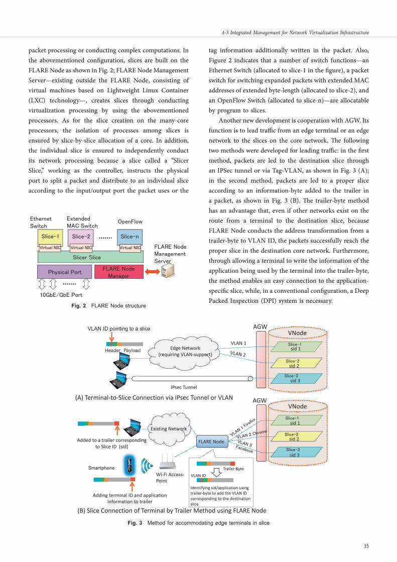
packet processing or conducting complex computations. In the abovementioned configuration, slices are built on the FLARE Node as shown in Fig. 2; FLARE Node Management Server—existing outside the FLARE Node, consisting of virtual machines based on Lightweight Linux Container (LXC) technology—, creates slices through conducting virtualization processing by using the abovementioned processors. As for the slice creation on the many-core processors, the isolation of processes among slices is ensured by slice-by-slice allocation of a core. In addition, the individual slice is ensured to independently conduct its network processing because a slice called a “Slicer Slice,” working as the controller, instructs the physical port to split a packet and distribute to an individual slice according to the input/output port the packet uses or the
tag information additionally written in the packet. Also, Figure 2 indicates that a number of switch functions—an Ethernet Switch (allocated to slice-1 in the figure), a packet switch for switching expanded packets with extended MAC addresses of extended byte-length (allocated to slice-2), and an OpenFlow Switch (allocated to slice-n)—are allocatable by program to slices.
Another new development is cooperation with AGW. Its function is to lead traffic from an edge terminal or an edge network to the slices on the core network. The following two methods were developed for leading traffic: in the first method, packets are led to the destination slice through an IPSec tunnel or via Tag-VLAN, as shown in Fig. 3 (A); in the second method, packets are led to a proper slice according to an information-byte added to the trailer in a packet, as shown in Fig. 3 (B). The trailer-byte method has an advantage that, even if other networks exist on the route from a terminal to the destination slice, because FLARE Node conducts the address transformation from a trailer-byte to VLAN ID, the packets successfully reach the proper slice in the destination core network. Furthermore, through allowing a terminal to write the information of the application being used by the terminal into the trailer-byte, the method enables an easy connection to the application-specific slice, while, in a conventional configuration, a Deep Packed Inspection (DPI) system is necessary.
Fig.F 2 FLARE Node structure
Slice-1 Slice-2 Slice-n
vSlicer Slice
Physical PortFLARE Node
Manager
FLARE Node Management Server
OpenFlowEthernet Switch
Extended MAC Switch
Virtual NIC Virtual NIC Virtual NIC
10GbE/GbE Port
Slice-1
Slice-2
Slice-3
Identifying sid/application using trailer‐byte to add the VLAN ID corresponding to the destination slice
AGWVNode
FLARE Node
Wi‐Fi Access‐Point
Smartphone
Adding terminal ID and application information to trailer
Header Payload
VLAN ID pointing to a slice
Edge Network(requiring VLAN‐support)
Existing Network
Added to a trailer correspondingto Slice ID (sid)
Slice-1
Slice-2
Slice-3
AGWVNode
IPsec Tunnel
VLAN 1sid 1
sid 2
sid 3
sid 1
sid 2
sid 3
Trailer ByteVLAN ID
(A) Terminal‐to‐Slice Connection via IPsec Tunnel or VLAN
(B) Slice Connection of Terminal by Trailer Method using FLARE Nodeジ
Fig.F 3 Method for accommodating edge terminals in slice
Title:J2015N-04-03.indd p35 2016/02/23/ 火 21:01:10
35
4-3 Integrated Management for Network Virtualization Infrastructure

3.2 Control and management mechanism: Abstraction and elasticity of resources
The purpose of an integrated management-type network virtualization platform is to enable flexible and integrated resource management through the abstraction of different types of physical network resources[2]. Our research and development realized integrated control and management with the transport network, through the extension of such abstract resource management scheme to the transport network. Such an integrated control and management mechanism is required for the following reasons. A net-work infrastructure that provides general services consists of two different networks, the “Service Network” that consists of service nodes to provide network services, and the “Transport Network” that connects and transmits packets between service nodes. The transport network transports packets independent of the services contents and is shared by multiple services. Even a network virtu-alization platform, because it consists of a service network composed of VNodes and a transport network composed of existing switches and routers, is required to control and manage the service network and the transport network in an integrated way. Figure 4 shows the configuration of the system implemented in our project; its target is the real-ization of the integrated control/management of a service network and a transport network. In the configuration, the following two components integrate with each other: the Service Network Controller (SNC), in charge of service-network control/management; and the Transport Network Controller (TNC), in charge of transport-network control/management. They are working together to accomplish the following task to establish link slivers at the timing
of slice creation: the allocation of the required resources to the transport path, or automatic creation of a transport path. The cooperation goes on in the following way: the SNC, treating transport network resources as an abstract transport path, notifies the TNC of the volume of resources of a transport path required for the establishment of a link sliver. The TNC allocates the required transport path with the prepared physical resources and provides it to SNC.
On the other hand, in order to ensure dynamic re-con-figuration of the resources allocated to a slice—this means “resource elasticity” is secured—for the purpose of keeping the service quality at a high level or accomplishing total optimization over the network, performance monitoring of each slice is indispensable[3]. The Network Virtualization Platform accomplishes such slice-performance monitoring in the following way to cope with the situation where indi-vidual slices have different topologies or identifiers: a NW Monitoring Manager was newly developed, which, obtain-ing the topology information and the slice information of a monitoring target slice from the SNC and TNC, determines on what points the monitoring should be done and sets up the filtering conditions to the points. Figure 5 shows the slice monitoring scheme based on cooperation between the Network Virtualization Platform Management System and the NW Monitoring Manager. The Developer who is an owner of the slice designates the slice to be performance-monitored and the points and time/date of monitoring using the Portal screen. Then, the Network Virtualization Platform Management System provides the NW Monitoring Manager with the necessary monitoring-link information and slice identifier, the NW Monitoring Manager sets up optical switches for switching monitoring points, and also
VirtualizationNode
SW/Router
Transport Network
Service Network
TNC
DeveloperSlice Creation/Deletion/Operation
Operator
SNC Operation ofTransport Network
Other Service Network
Slice
Creation
Fig.F 4 Configuration of service network and transport network
36 Journal of the National Institute of Information and Communications Technology Vol. 62 No. 2 (2015)
Title:J2015N-04-03.indd p36 2016/02/23/ 火 21:01:10
4 Core Technologies for the New-Generation Network

sets up the PRESTA 10G’s filter; then, after the completion of the monitoring, the NW Monitoring Manager notifies the results of monitoring to the Developer, through the Network Virtualization Platform Management System.
3.3 Resource control: Securing resource independence/isolation
Avoiding resource interference between slices is criti-cal for implementing network virtualization. For instance, it must not be allowed that a certain slice monopolizes bandwidth or produces unfair delays in other slices. A function for avoiding such interference is called “resource isolation.” We have conducted our research on avoiding resource interference, according to the following idea: “For avoiding interference among terminals (end-to-end), resource isolation must be secured entirely over the Network Virtualization Platform, and Redirector is the most important for accomplishing such resource isola-tion.” In a conventional network virtualization platforms, resource isolation had been realized, although in a basic form[4]. We improved upon such a conventional platform in our project. So, we will first describe below such a basic resource isolation method, and then focus on what was improved in our project.
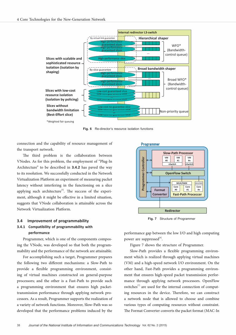
The outlines of the abovementioned basic resource isolation functions that will be done in a Redirector[4] are described as follows:
The Redirector has a built-in L3-switch performing such functions as a VLAN Function, IP Routing Function or QoS Function. For a QoS function, the switch has such features as Weighted Fair Queuing (WFQ) and Policing. Redirector, using those functions, accomplishes resource isolation. For example, a WFQ function carries out flow-output bandwidth control by putting a packet in a queue
prepared for individual flows, and Redirector accomplishes high-performance bandwidth control for each slice using this mechanism. However, this method has been applicable only to a limited number of slices for huge bandwidth because in this method it is relatively expensive to use high-speed memory for queuing. On the other hand, a policing function is low cost because it does not require memory. Therefore, a policing function is applicable to more than several tens of slices for resource isolation functions. However, this method degrades performance compared with the WFQ method, so it causes higher packet loss or more severe slice jitter.
There are three problems to be solved with the basic method mentioned above. The first problem is to provide resource isolation by the WFQ function for as many slices as possible. At the same time, this problem is to realize more sophisticated control through improving the resource isola-tion function. In a conventional Redirector, the bandwidth control is carried out for all of the link slivers connected to a node sliver[4]. We improved the bandwidth control for each link sliver. We added a new hardware component called a hierarchical shaper on the internal switch of Redirector to address this problem and achieved scalable and sophisti-cated resource isolation function (Fig. 6). The second is to suppress end-to-end interference. This was difficult because Redirector’s resource isolation function works without any cooperation with the other components of VNode (particu-larly Programmer), or other component of the virtualiza-tion platform such as AGW and the transport network. To address this problem, the system was improved so that (1) the resource management of Programmer and Redirector are able to collaborate with each other and (2) the Network Virtualization Platform Management System has the ca-pability of resource management for Redirector-to-AGW
TNC
SNC
Portal NW monitoring manager
NW Virtualization Platform Management System
・Setting Monitoring Schedule・Designating Monitoring Links・Slice Identification Information・Commanding monitoring Start/Stop・Sharing monitoring ‐REsult
Monit‐oring IF
Screen for designating monitoring link: Example Screen for setting monitoring
schedule: ExampleScreen for displaying
monitoring results
PRESTA 10G
Optical Switch
Virtual‐izationNode
L2 SW
Monit‐oring IF
・Designating monitoring pointson virtual NW
・Choosing monitoring time/date・Displaying/browsing monitoring results
Developer
Fig.F 5 Collaboration scheme of Network Virtualization Platform Management System with NW Management Manager
Title:J2015N-04-03.indd p37 2016/02/23/ 火 21:01:10
37
4-3 Integrated Management for Network Virtualization Infrastructure
connection and the capability of resource management of the transport network.
The third problem is the collaboration between VNodes. As for this problem, the employment of “Plug-In Architecture” to be described in 3.4.2 has paved the way to its resolution. We successfully conducted in the Network Virtualization Platform an experiment of measuring packet latency without interfering in the functioning on a slice applying such architecture[5]. The success of the experi-ment, although it might be effective in a limited situation, suggests that VNode collaboration is attainable across the Network Virtualization Platform.
3.4 Improvement of programmability3.4.1 Compatibility of programmability with
performanceProgrammer, which is one of the components compos-
ing the VNode, was developed so that both the program-mability and the performance of the network are attainable.
For accomplishing such a target, Programmer prepares the following two different mechanisms: a Slow-Path to provide a flexible programming environment, consist-ing of virtual machines constructed on general-purpose processors; and the other is a Fast-Path to provide such a programming environment that ensures high packet-transmission performance through applying network pro-cessors. As a result, Programmer supports the realization of a variety of network functions. Moreover, Slow-Path was so developed that the performance problems induced by the
performance gap between the low I/O and high computing power are suppressed[6].
Figure 7 shows the structure of Programmer.Slow-Path provides a flexible programming environ-
ment which is realized through applying virtual machines (VM) and a high-speed network I/O environment. On the other hand, Fast-Path provides a programming environ-ment that ensures high-speed packet transmission perfor-mance through applying network processors. OpenFlow switches[7] are used for the internal connection of comput-ing resources in the device. Therefore, we can construct a network node that is allowed to choose and combine various types of computing resources without constraint. The Format Converter converts the packet format (MAC-In
Fig.F 6 Re-director’s resource isolation functions
Fig.F 7 Structure of Programmer
Programmer
Controller
Slow‐Path ProcessorVM#0
VM#1
VM#n
vSwitch vSwitch
OpenFlow Switch
Fast‐Path Proceccer
Core#0
Core#1
Core#n
MUX/DMX MUX/DMX
FormatConverter
Programmer
Redirector
Internal redirector L3‐switch
Layered shaper
Broad bandwidth shaper
Broad WFO* (Bandwidth‐control queue)
Non‐priority queue
Slices with scalable and sophisticated resource isolation (isolation by shaping)
Slices with low‐cost resource isolation (isolation by policing)
Slices without bandwidth limitation (Best‐Effort slice)
High‐performance‐guaranteed slices
WFO* (Bandwidth‐control queue)
High‐performance‐guaranteed slices
High‐performance slice
High‐performance‐guaranteed slices
Low cost gua anteed slice
High‐performance‐guaranteed slices
Low cost no guarantee slice…
Low cost no gua antee sliceLow‐cost no‐guarantee slice
…Low cost gua anteed sliceLow‐cost guaranteed slice
…
…
By‐virtual‐link guarantee
By‐slice guarantee
*Weighted fair queuing
Hierarchical shaper
38 Journal of the National Institute of Information and Communications Technology Vol. 62 No. 2 (2015)
Title:J2015N-04-03.indd p38 2016/02/23/ 火 21:01:10
4 Core Technologies for the New-Generation Network

MAC format and VLAN format) between Redirector and Programmer.
The following is a description of how the improvement in the performance of Slow-Path was attained: The net-work I/O performance was improved, as shown in Fig. 8, through (1) the application of switch-offload technique, and (2) the employment of 10GbE compatible hardware components. Figure 9 shows the performance improve-ment in Slow-Path accomplished by (1) and (2)—the plots and graphs specified by “onload” represents results before employment (1) and (2), and those specified by “offload,” represents results after employment (1) and (2). The plots designated by “CPU Load SUM” are the sum of the CPU utilization rates of Guest OSs, and the plots designated by “CPU Load HOST” are the utilization rate of the host OS. Figure 9 indicates that, through the application of (1) and (2), the performance in throughput was improved and Host OS’s utilization rate was lowered.
3.4.2 Programmability extension through applying plug-in functional modules
Programmability extension via plug-ins was studied
aiming at the following two targets. The first target is to ensure VNode evolution (adding functions) through add-ing programs (software)[8]; although VNode is allowed to use prepared types of node slivers and link slivers. As for node slivers, two types of node slivers of Slow-Path and Fast-Path are prepared as mentioned earlier. As for link slivers, a single type based on Generic Encapsulation Over IP (GRE/IP) is available. We can program the Slow-Path freely, but a situation will arise of extension of program-mability through the employment of other types of node slivers and link slivers for fulfilling special requirements. Hence, the first target is to extend the VNode infrastruc-ture architecture so that it is allowed to add new types of node slivers and link slivers than those prepared into the infrastructure. The second target is to develop such a method that enables simple programming of the VNode infrastructure for functional extension. VNode developers will face difficulties in programming when such functional extension is realized through the addition of such special-ized hardware components as network processors. If the second target is accomplished, such programming difficul-ties will be removed.
The following three items were newly developed for proving the validity of the abovementioned method for removing such programming difficulty (Fig. 10). The first is the programming language and development environ-ment of the open processing platform for Fast-Path[9]. The programming language is named “Phonepl” and its programming environment has been partially developed. Note that this language and programming environment are required to accomplish the second target. The second developed item is the mechanism for embedding the Fast-Path modules in a VNode[8]. They make it possible to incorporate the Fast-Path module which is mentioned above or other types of Fast-Path modules. The second item
Fig.F 8 Improvement in Slow-Path performance
VMvSwitch
VMvSwitch
Server+Virtualization
Inside‐Node NW‐Control Server (performing the integrated management
of inside‐node switches)
InterconnectSwitch
HW Offload
HW Offload
Information Storage DB
Redirector
Programmer
Slow-Path
VM
VM
Enhanced by 10GbE Components
①
③
ProgrammerManagement
OffloadJudgmentControl
VM
Driver
Program
NIC
Distribution/Multiplexing
Control
SR‐IOV
OffloadOnload
vSwitch
②Fast‐Path(NPU)
Fig.F 9 Improvement in Slow-Path performance (when receiving)
1683
763802
7643
9268 9327 9255.8
2918
2137
1271
9281 9195
0
1000
2000
3000
4000
5000
6000
7000
8000
9000
10000
1 2 4 8 16 64The number of VMs
Thro
ugh
put
[Mbp
s]
0
20
40
60
80
100
CP
U L
oad
[%]
Throughput (onload)
Throughput (offload)
CPU Load HOST (onload)
CPU Load HOST (offload)
CPU Load SUM (onload)
CPU Load SUM (offload)
Fig.F 10 Programmability expansion by using plug-in functional modules: Developed items for proof of concept
VNode Control-Plug-in I/F (CPII)
Data-Plug-in I/F (DPII)
Plug-inExpanded VNode
Control-Plane Component
Data Plug-in (Packet Processing)
Data-Plane Component (Re-
Director Body, etc.)
C-PlaneD-Plane
Control Plug-in
Plug-in to Plug-in I/F
Fast-Path Processing (Plug-in DevelopmentEnvironment)
Phonepl (Plug-In Description High-Level Language)
InfrastructureDeveloper
Slice Developer
Embedding Fast-Path
Processing Function
New VirtualLink/Node Type
Title:J2015N-04-03.indd p39 2016/02/23/ 火 21:01:10
39
4-3 Integrated Management for Network Virtualization Infrastructure

enables the construction of the operation environment. The third-developed is the mechanism for embedding an offload switch/router-function in a VNode[10]. Note that the third developed item, involved in the accomplishment of the first target, enables a VNode developer to use, as a module, the functions possessed by the VNode components, particu-larly by the Redirector, but hidden to the developer and unusable from a slice.
3.5 Edge virtualization technologies: Programming technologies for network access
Edge virtualization technologies have been developed aiming for the realization of the wide use of more efficient network services and the provision of application-oriented network functions, through expanding the slice coverage from the core network to edge networks for the purpose of enabling the implementation of a new network function at its best position in the network structure. In this subsec-tion, the research and development activities, for the pur-pose just mentioned, of a dynamic network access control platform, are introduced. The platform, handling terminals such as a mobile terminal involving more than one network of different characteristics, dynamically switches the con-nection to access networks of different characteristics, and accomplishes collaboration with the services carried out on VNode through allowing the network-side to conduct such controls[11].
Figure 11 shows the dynamic terminal network access control platform that was implemented in our project. The following is the outline of how the platform and other components work:
We implemented an Edge Node on an Android
terminal. Our Edge Node is able to conduct the following controls: for each application, identifying the slice able to communicate, according to the policy instructed by Edge SNC; and for each slice, determining what type of mobile network to use as an access network.
The Edge Gateway is a gateway relaying the communi-cation between an edge-network slice and a core-network slice. It connects to AGW, a gateway device in the core area, to relay the communication between the Node Sliver on VNode and applications on the Edge Node. The Edge SNC conducts the following: creating/deleting/configur-ing edge-network slices, through issuing an execution command of the connection to the core-network slice on VNode. Moreover, the Edge SNC, through communicat-ing with the SNC, the integrated management device of VNode, exchanges the information necessary to establish the connection between the edge-network slice and the core-network slice.
The mechanisms mentioned above enable the by-application accommodation, in a slice that is a combination of an edge-network slice and a core-network slice, of the applications existing in the Edge Network through an arbitrary access network.
3.6 Gateway function improvement: Authentication capability
For using a slice on the Network Virtualization Platform, the end-to-end-connectivity covering even physical devices or networks must be ensured. Furthermore, such connec-tion must be established using various protocols including proprietary protocols. Such connectivity is ensured by AGW (as shown in Fig. 12) placed at the edge of a slice to ensure the following:
AGW
R
SNC
Wireless NW
Core Area
EdgeNode
EdgeNode
Edge Area
VNode SystemTerminal Network AccessDynamic Control Platform
EdgeGateway
Edge SNC
Core Network: JGN‐XEdge Network
Fig.F 11 Terminal Network Access Dynamic Control Platform
40 Journal of the National Institute of Information and Communications Technology Vol. 62 No. 2 (2015)
Title:J2015N-04-03.indd p40 2016/02/23/ 火 21:01:10
4 Core Technologies for the New-Generation Network
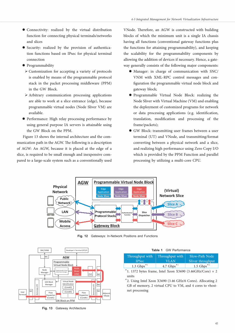
z Connectivity: realized by the virtual distribution function for connecting physical terminals/networks and slices
z Security: realized by the provision of authentica-tion functions based on IPsec for physical terminal connection
z Programmability Customization for accepting a variety of protocols
is enabled by means of the programmable protocol stack in the packet processing middleware (PPM) in the GW Block.
Arbitrary communication processing applications are able to work at a slice entrance (edge), because programmable virtual nodes (Node Sliver VM) are available.
z Performance: High relay processing performance by using general purpose IA servers is attainable using the GW Block on the PPM.
Figure 13 shows the internal architecture and the com-munication path in the AGW. The following is a description of AGW: An AGW, because it is placed at the edge of a slice, is required to be small enough and inexpensive com-pared to a large-scale system such as a conventionally used
VNode. Therefore, an AGW is constructed with building blocks of which the minimum unit is a single IA chassis having all functions (conventional gateway functions plus the functions for attaining programmability), and keeping the scalability for the programmability components by allowing the addition of devices if necessary. Hence, a gate-way generally consists of the following major components:z Manager: in charge of communication with SNC/
VNM with XML-RPC control messages and con-figuration the programmable virtual node block and gateway block;
z Programmable Virtual Node Block: realizing the Node Sliver with Virtual Machine (VM) and enabling the deployment of customized programs for network or data processing applications (e.g. identification, translation, modification and processing of the frame/packets);
z GW Block: transmitting user frames between a user terminal (UT) and VNode, and transmitting/format converting between a physical network and a slice, and realizing high performance using Zero Copy I/O which is provided by the PPM Function and parallel processing by utilizing a multi-core CPU.
eway Block
Programmable Virtual Node Block
Slice A
Slice B
Slice C
AuthenticationFunction
SliceDispatcher
grammabletocol Stacks
PublicNetwork
LAN
MobileAccess
AGWPhysicalNetwork (Virtual)
Network SliceNode Sliver Node Sliver Node Sliver
EdgeApplication
EdgeApplication
EdgeApplication
GW Block on PPM
ProgrammableVirtual Node Block
Virtual NodeIdentification
FlowDispatcher(Core#1)
AGW
UserTerminal Adjacent
VNode
NIC
(Core#2)
(Core#3)
NIC
NIC
Programmable VirtualNode Block Manager
NIC
NodeManager
GW BlockManager
FlowDispatcher(Core#n)
NIC
SNC/VNM Developer’s Terminal (DT)/IS
OVS
NodeSliver(VM)
Zerocopy
I/O
Zerocopy
I/O
Throughput with IPSec
Throughput with VLAN
Slow-Path Node Sliver throughput
1.3 Gbps*1 4.7 Gbps*1 1.5 Gbps*2
* 1. 1372 bytes frame, Intel Xeon X5690 (3.46GHz/Core) × 2 units* 2. Using Intel Xeon X5690 (3.46 GHz/6 Cores). Allocating 2
GB of memory, 2 virtual CPU to VM, and 4 cores to vhost-net processing
Fig.F 12 Gateways: In-Network Positions and Functions
Fig.F 13 Gateway Architecture
TableT 1 GW Performance
Title:J2015N-04-03.indd p41 2016/02/23/ 火 21:01:10
41
4-3 Integrated Management for Network Virtualization Infrastructure

Table 1 shows the performance of the enhanced AGW Device.
4 Deployment on testbed and international federation
We deployed the Network Virtualization Platform on the JGN-X Testbed for application developers for their experiments. As shown in Fig. 14, seven virtualization nodes (VNode), two simplified virtualization nodes, and six access gateways (AGW) were deployed nationwide.
As of now, the testbed is used at a rate of approximately 40 slices per month.
Furthermore, we conducted international federation experiments; through a simplified virtualization node (NC) installed by the NICT at the University of Utah, U.S., a network virtualization testbed constructed on JGN-X was connected with the GENI virtualization testbed in United States, and the Fed4FIRE network virtualization testbed in Europe. The federation experiment has proved the validity of the slice construction in a global multi-domain environment.
FUkuokaOsaka
Sendai
NICT Koganei
USA
International Line
100G10G10G
100G10G
10G
100G10G1GDF
Legent
10G10G
10G
10G
1G
10G
Tokyo
Nagoya
Hokuriku
AGW AGW AGW
AGW
AGW
AGW
NTT Yokosuka
Metropolitan Tokyo
NICT Otemachi NICT Hakusan
VN
VN
VN
NC
NC
VN
NC
AccessGatewayVNode
Network Connector
VNVN
VN
AGW
VN
UTNC
University of Utah
NICT Koganei
0
10
20
30
40
50
60
: The number of Slices
: The number of users
Slice-A
Slice-B
Fig.F 14 Deployment of network virtualization platform on JGN-X
InterfaConvers
GK
GW
InteConversion
GK
GW
InterfaceConversion
GK
GW
ProtoGENI Testbed
JGN‐XNetwork‐Virtualiza
Testbed
Fed4 FIRE Testbed
FederatedNetwork‐Virtualization Testbeds
VNode (installed at the University of Utah)
Data
SEP(Slice Exchange Point)
Virtualization NodeAPI
GK (Gate Keeper): Control Signal Interface Conversion FunctionGW (Gateway): Interface Conversion Function for Contents Data
Abstract Common API 2.0
Control Signal
Control Signal
Fed4FIRE API
ProtoGENI API
Fig.F 15 Configuration of Japan-US-Europe Federation
42 Journal of the National Institute of Information and Communications Technology Vol. 62 No. 2 (2015)
Title:J2015N-04-03.indd p42 2016/02/23/ 火 21:01:10
4 Core Technologies for the New-Generation Network
Figure 15 shows the configuration of the international federation experiment. Each network virtualization test-bed is federated through the slice exchange point (SEP) installed in the NC at the University of Utah. Gaps caused by the mutual differences in the testbed implementation methods are filled at the SEP through the abstraction of the individual testbed interfaces into common APIs.
5 Conclusion
We have conducted research and development activities on the integrated-type network virtualization platform. It has been revealed that the platform has the potential for solving a variety of problems that the present information communication systems have. We are now planning to evaluate the platform from the point of view of a new-generation information communication infrastructure.
Acknowledgments
The authors acknowledge here that the research and development achievements described in this paper were accomplished as a NICT contract research titled “Research and Development of Network Virtualization Platform Technologies Supporting New-Generation Network.”
References 1 Akihiro Nakao, “VNode: A Deeply Programmable Network Testbed Through
Network Virtualization,” The 3rd domestic conference, IEICE Technical Committee on Network Virtualization (NV), Mar. 2, 2012.
2 Yohei Katayama, Kazuhisa Yamada, Katsuhiro Shimano, and Akihiro Nakao, “Hierarchical Resource Management System on Network Virtualization Platform for Reduction of Virtual Network Embedding Calculation”, APNOMS2013, P2-1, 2013
3 Seiki Kuwahara, Yohei Katayama, and Kazuhisa Yamada, “Adaptive Traffic Monitoring System for Virtualized Networks,” Proceedings of the IEICE general conference / the Institute of Electronics, Information and Communication Engineers, 1995. (in Japanese)
4 Kanada, Y., Shiraishi, K., and Nakao, A., “Network-resource Isolation for Virtualization Nodes”, IEICE Trans. Commun., Vol. E96-B, No. 1, pp. 20-30, 2013, DOI: 10.1587/transcom.e96.b.20.
5 Kanada, Y., “Extending Network-virtualization Platforms by using a Specialized Packet Header and Node Plug-ins”, 22nd International Conference on Software, Telecommunications and Computer Networks (SoftCom 2014), September 2014, DOI: 10.1109/softcom.2014.7039092.
6 Satoshi Kamiya et al., “A Proposal of Network Processing Node to emerging Advanced Network Virtualization Infrastructure,” The 3rd domestic conference, IEICE Technical Committee on Network Virtualization (NV), Mar. 2, 2012. (in Japanese)
7 [OpenFlow] OpenFlow Switch Consortium, OpenFlow Switch Specification, version 1.0.0, Dec, 2009.
8 Kanada, Y., “A Method for Evolving Networks by Introducing New Virtual Node/link Types using Node Plug-ins,” 1st IEEE/IFIP International Workshop
on SDN Management and Orchestration (SDNMO’14), May 2014, DOI: 10.1109/noms.2014.6838417.
9 Kanada, Y., “High-Level Portable Programming Language for Optimized Memory Use of Network Processors”, Communications and Network, Vol.7 No.1, 2015, DOI: 10.4236/cn.2015.71006.
10 Kanada, Y., “Providing Infrastructure Functions for Virtual Networks by Applying Node Plug-in Architecture”, Workshop on Software Defined Networks for a New Generation of Applications and Services (SDN-NGAS 2014), August 2014 & Procedia Computer Science, Vol. 34, pp. 661-667, 2014, DOI: 10.1016/j.procs.2014.07.094.
11 Takahiro IIHOSHI, et al., “A Slice Extension Architecture Using Smart-devices for Flexible Network Service Experiments on VNode,” The 9th domestic confer-ence, IEICE Technical Committee on Network Virtualization (NV), Apr. 11, 2014. (in Japanese)
Kazuhisa YAMADASenior Research Engineer, Future Networking Research Group, Media Innovation Laboratory, NTT Network Innovation LaboratoriesNetwork
Akihiro NAKAO, Ph.D.Professor, Interfaculty Initiative in Information Studies, Graduate School of Interdisciplinary Information Studies, The University of TokyoNetwork, Computer Science
Yasusi KANADA, Ph.D.Senior Researcher, Network Research Department, Center for Technology Innovation - Information and TelecommunicationsNetwork, Computer Vision
Yoshinori SAIDA Manager, System Integration & Services Technologies Management Division, Technological Strategy Planning Department, NEC Network
Koichiro AMEMIYADistributed Systems Software Project,Software Laboratory, Fujitsu Labratories Ltd.Cloud Computing, Network
Title:J2015N-04-03.indd p43 2016/02/23/ 火 21:01:10
43
4-3 Integrated Management for Network Virtualization Infrastructure