
Integral design concepts of advanced water cooled reactors
233
IAEA-TECDOC-977 Integral design concepts of advanced water cooled reactors Proceedings of a Technical Committee meeting held in Obninsk, Russian Federation, 9-12 October 1995 INTERNATIONAL ATOMIC ENERGY AGENCY
Transcript of Integral design concepts of advanced water cooled reactors

IAEA-TECDOC-977
Integral design concepts ofadvanced water cooled reactors
Proceedings of a Technical Committee meetingheld in Obninsk, Russian Federation, 9-12 October 1995
INTERNATIONAL ATOMIC ENERGY AGENCY

The IAEA does not normally maintain stocks of reports in this series.However, microfiche copies of these reports can be obtained from
IN IS ClearinghouseInternational Atomic Energy AgencyWagramerstrasse 5P.O. Box 100A-1400 Vienna, Austria
Orders should be accompanied by prepayment of Austrian Schillings 100,-in the form of a cheque or in the form of IAEA microfiche service couponswhich may be ordered separately from the IN IS Clearinghouse.

The originating Section of this publication in the IAEA was
Nuclear Power Technology Development SectionInternational Atomic Energy Agency
Wagramerstrasse 5PO Box 100
A-1400 Vienna, Austria
INTEGRAL DESIGN CONCEPTS OF ADVANCED WATER COOLED REACTORSIAEA, VIENNA, 1997IAEA-TECDOC-977ISSN 1011^289
©IAEA, 1997
Printed by the IAEA in AustriaNovember 1997

FOREWORD
Nuclear power has played a significant role in the supply of electricity over the past two decades.The two major nuclear accidents, namely Three Mile Island and Chernobyl, have considerablyaffected its further growth. Reconsideration of reactor design and safety aspects of nuclear powerhas been an active area of development. Elimination of some accident scenarios, simplificationof systems and reliance on natural phenomena have been a major part of these activities, whichled to the development of new design concepts.
Under the sub-programme on non-electrical applications of advanced reactors, the InternationalAtomic Energy Agency has been providing a worldwide forum for exchange of information onintegral reactor concepts. Two Technical Committee meetings were held in 1994 and 1995 on thesubject where state-of-the-art developments were presented. Efforts are continuing for thedevelopment of advanced nuclear reactors of both evolutionary and innovative design, forelectricity, co-generation and heat applications. While single purpose reactors for electricitygeneration may require small and medium sizes under certain conditions, reactors for heatapplications and co-generation would be necessarily in the small and medium range and need tobe located closer to the load centres.
The integral design approach to the development of advanced light water reactors has receivedspecial attention over the past few years. Several designs are in the detailed design stage, someare under construction, one prototype is in operation. A need has been felt for guidance on anumber of issues, ranging from design objectives to the assessment methodology needed to showhow integral designs can meet these objectives, and also to identify their advantages and problemareas.
The technical document addresses the current status of the design, safety and operational issuesof integral reactors and recommends areas for future development.

EDITORIAL NOTE
In preparing this publication for press, staff of the IAEA have made up the pages from theoriginal manuscripts as submitted by the authors. The views expressed do not necessarily reflectthose of the IAEA, the governments of the nominating Member States or the nominatingorganizations.
Throughout the text names of Member States are retained as they were when the text wascompiled.
The use of particular designations of countries or territories does not imply any judgement bythe publisher, the IAEA, as to the legal status of such countries or territories, of their authoritiesand institutions or of the delimitation of their boundaries.
The mention of names of specific companies or products (whether or not indicated asregistered) does not imply any intention to infringe proprietary rights, nor should it be construedas an endorsement or recommendation on the part of the IAEA.
The authors are responsible for having obtained the necessary permission for the IAEA toreproduce, translate or use material from sources already protected by copyrights.

CONTENTS
SUMMARY . . . . . . . . . . . . . . . . . . . . . . . . . . . . . . . . . . . . . . . . . . . . . . . . . . . . . . . . . . . . . . . . . . . . . 7
DEVELOPMENT PROGRAMMES AND CONCEPTUALDESIGN DESCRIPTIONS
New generation nuclear power units of PWR type integral reactors . . . . . . . . . . . . . . . . . . . . . . . . 25P.M. Mitenkov, A. V. Kurachen Kov, V.A. Malamud,Yu.K. Panov, B.I. Runov, L.N. Flerov
Reactor type choice and characteristics for a small nuclear heat andelectricity co-generation plant . . . . . . . . . . . . . . . . . . . . . . . . . . . . . . . . . . . . . . . . . . . . . . . . . 35Liu Kukui, Li Manchang, Tang Chuanbao
The CAREM project: Present status and development activities . . . . . . . . . . . . . . . . . . . . . . . . . . . 47H.J. Boado Magan, J.P. Ordonez, A. Hey
An integral reactor design concept for a nuclear co-generation plant . . . . . . . . . . . . . . . . . . . . . . . . 57D.J. Lee, J.I. Kirn, K.K. Kirn, M.H. Chang, K.S. Moon
An integral design of NHR-200 . . . . . . . . . . . . . . . . . . . . . . . . . . . . . . . . . . . . . . . . . . . . . . . . . . . . . 71Xue Dazhi, Li Jicai, Chang Dafeng
An evolutionary approach to advanced water cooled reactors . . . . . . . . . . . . . . . . . . . . . . . . . . . . . 77A.R. Antariksawan, I. Subki
The inherently safe immersed system (ISIS): Safety and economic aspects . . . . . . . . . . . . . . . . . . 85L. Cinotti
An integrated nuclear reactor unit for a floating low capacity nuclear power plantdesigned for power supply in remote areas with difficult access . . . . . . . . . . . . . . . . . . . . . . 97A.N. Achkasov, G.I. Grechko, O.G. Gladkov,V.L. Pavlov, V.N. Pepa, V.A. Shishkin
An autonomous nuclear power plant with integrated nuclear steam supply systemdesigned for electric power and heat supply in remote areas with difficult access . . . . . . . . 107L.A. Adamovich, G.I. Grechko, B.D. Lapin, V.K. Ulasevich, V.A. Shishkin
IRIS: Minimizing internal energy accumulated in the primary circuit of an integralPIUS type PWR with natural circulation . . . . . . . . . . . . . . . . . . . . . . . . . . . . . . . . . . . . . . . . . 119O.G. Griboriev, M.P. Leonchyk, D.E. Skorikov, V.V. Chekunov
The Light water integral reactor with natural circulation of the coolant atsupercritical pressure V-500 SKDI . . . . . . . . . . . . . . . . . . . . . . . . . . . . . . . . . . . . . . . . . . . . . 123V.A. Silin, A.M. Antonov, A.M. Afrov, M.P. Nikitenko, A. V. Buhtoyarov
The MRX integral reactor: Maintenance and cost evaluation for ship application . . . . . . . . . . . . . . 137A. Yamaji, J. Shimazaki, M. Ochiai, T. Hoshi
Concept, experimental and calculational investigations of a micromodule reactor . . . . . . . . . . . . . 149Yu.I. Orekhov, R.S. Pomet'ko, Yu.A. Sergeev
SPECIFIC SYSTEMS AND ANALYSIS
Emergency heat removal in the integral water cooled ABV-6 reactor for theVolnolom floating nuclear power p l a n t . . . . . . . . . . . . . . . . . . . . . . . . . . . . . . . . . . . . . . . . . . 161Yu.D. Baranaev, Yu.I. Orekhov, Yu.A. Sergeev, I.M. Shvedenko,Yu.P. Fadeev, V.M. Vorobyev
Highly efficient cassette steam generator for integral reactors . . . . . . . . . . . . . . . . . . . . . . . . . . . . . 171P.M. Mitenkov, V.M. Rulev
LOCA features peculiar to an integral water cooled PWR . . . . . . . . . . . . . . . . . . . . . . . . . . . . . . . . 179Ya.K. Kozmenkov, Yu.I. Orekhov
Study of the kinetics of the steam-zirconium reaction using aone rod assembly model . . . . . . . . . . . . . . . . . . . . . . . . . . . . . . . . . . . . . . . . . . . . . . . . . . . . . 1 8 9S.G. Kaliakin, Yu.P. Dzhusov, R.V. Shumsky, Yu. Stein

Loss of coolant experiments for the test nuclear heating reactor . . . . . . . . . . . . . . . . . . . . . . . . . . . 195Ma Changwen, Bo Jinhai, Ja Haijun, Gao Zuying
OPERATIONAL, MANUFACTURING AND DECOMMISSIONING ASPECTS
CAREM: Operational aspects, major components and maintainability . . . . . . . . . . . . . . . . . . . . . . 207J.P Ordonez
Problems m manufacturing and transport of pressure vessels of integral reactors . . . . . . . . . . . . . . 217J. Krdlovec
Radiological aspects of integral nuclear reactor decommissioning . . . . . . . . . . . . . . . . . . . . . . . . . 227Y.S. Kuul, A V. Pichugin, OB. Samoilov
LIST OF PARTICIPANTS . . . . . . . . . . . . . . . . . . . . . . . . . . . . . . . . . . . . . . . . . . . . . . . . . . . . . . . 239

SUMMARY
1. INTRODUCTION
Many developing countries are experiencing a rapid growth of their economiesand an increasing need for the supply of both heat and electrical energy. The presentprimary energy production is based predominantly on fossil fuels, adding to the CO2burden on the environment. Nuclear power has the potential to bring about asubstantial reduction in C02 releases arising from both heat and electricity generation.Although there was a rapid growth in the seventies and early eighties, in the nuclearshare of total electricity generation, several factors including the impact of the ThreeMile Island and Chernobyl accidents have resulted in dampening further growth. Forharnessing the potential benefits of nuclear energy in meeting the future needs of bothheat and electricity, it is necessary to develop cogeneration nuclear plants having thefollowing characteristics:
• Low capital investment to reduce the financial risk.• Construction period of 5 years or less to improve the economics of nuclear
heat and power generation.• High operational reliability through simplification of the plant systems.• Enhanced safety features enabling siting near densely populated areas.
In response to these needs nuclear power plant designers in many countrieshave been developing new designs including integral reactors. Integral reactors areheat and/or power generation reactors, in which the primary coolant systemcomponents including steam generators(SGs), pressurizers and pumps are containedwithin the reactor pressure vessel (RPV). The current loop type power reactors havethese components located outside the RPV.
The purpose of this report is to provide up-to-date technical information on thecurrent status of the design and development of integral reactors in the Member States,based on information presented in two technical committee meetings organized by theAgency on the subject. Important aspects regarding integral reactor design anddevelopment are highlighted in the summary and the presented papers are includedunder the following headings:
• Development programmes and conceptual design descriptions.• Specific systems and analyses.• Operational, manufacturing and decommissioning aspects.
2. HIGHLIGHTS OF THE MEETING
The rated power of current integral reactor designs is limited to 700 MWe dueto manufacturing limitations in the size of the RPV. The maximum diameter of theRPV is limited to 7 m, based on present technological capabilities. The steamgenerators have to be of a special compact design with a high power density to enabletheir location inside the RPV.
In-service inspection(ISI), maintenance and replacement of equipment andcomponents is recognized to be more difficult as a result of the compactness of the

integral reactor designs and therefore, these aspects have received special attention inthe design stage itself Some unique solutions and special tools have been developedfor this purpose
The design characteristics are chosen to enhance nuclear safety and thus enablesiting close to population centers. Decommissioning is also facilitated due to theavailability of a fairly large RPV which can be used to store all the active componentsfor a few decades in a safe manner
New concepts of integral designs are being developed in the Republic of Koreaand the Russian Federation In other countries, some modifications to existing designshave been undertaken Other design areas receiving active attention include safety-related heat removal systems for integral reactors, design of compact steam generatorsand decommissioning aspects
From operational point of view, integral reactor designs do not differ inprinciple from loop type reactors The principal advantages of integral reactors overcurrent generation loop type reactors include the following:
• Enhanced safety level due to the location of primary coolant circuit withinthe RPV, in particular, a reduction in the probability of accidentsaccompanied by core damage
• Use of natural convection principle in the design of the primary coolantcircuit not only provides a passive system for emergency decay heatremoval, but also permits design of natural circulation reactors operating atrated output
• Reduction of neutron fluence on the reactor vessel to a negligible levelenhances RPV life substantially
• Significant increase in shop-fabrication of the reactor systems reduces thevolume of assembly work at site, and improves conditions forimplementation of quality control procedures.
• Stringent requirements of leak tightness for the outer containment shell arerelaxed as a closely fitted steel containment vessel called guard vesselfunctions as the first containment barrier A reinforced concrete shell wouldbe adequate as an outer containment for protection from external effectsConsequently, requirements of special safety systems for primary coolantinventory control and decay heat removal are also substantially simplified
• Potential reduction in construction time improves the economics of integralreactors
• Simplification of decommissioning work enables an earlier reuse of the site
Aspects currently receiving greater attention from designers of integral reactorsinclude the following"
• Significant increase in overall dimensions and weight of the RPV resulting inthe need to employ special handling and transport facilities duringconstruction/assembly work
• Restriction of maximum reactor power capacity to 700 MWe as aconsequence of limitation in allowable overall dimensions due to constraintsin production capability of the industry

• Special design characteristics of the steam generators such as compactnessand high power density which have a critical impact on the RPV dimensions
• Designs to facilitate comprehensive planned maintenance for trouble-freeoperation and replacement of major components.
• Use of nitrogen gas for pressurization
3. STATUS OF DESIGN AND DEVELOPMENT WORK IN MEMBER STATES
3 1 Argentina
Design and development work for the Argentinean project called CAREM iscontinuing The project is ten years old and the initial design power level was 15 MWeThe current work is on a 25 MWe reactor, with thought being given to a 100 MWereactor. Engineering for the 25 MWe plant is scheduled for completion by the end of1996. Financial, political and siting decisions are expected to be made in 1996, which iffavorable, will lead to construction in 1997. Experimental work is under way in a highpressure loop to study critical heat flux (CHF) and dynamic response, and to make acomprehensive study of the reactor physics of the core in the RA-8 critical facilityDevelopment and testing is being carried out on the core internals, control rod drives& position indicators and the reactor protection system, especially the trip system
3.2. China
Loss-of-coolant experiments are being carried out for the Chinese nuclearheating reactor (NHR200). A test loop has been in operation since 1989, and allowstests on the three possible positions for a break to occur, (i) pipes on the upperplenum, (ii) steam generator pipe break and (iii) boron injection pipe below the vesselwater level. Experiments have shown good agreement with the results of calculationson the influence of the break position on RPV water level, on discharge quality andhence on the depressurization rate. Depressurization is quite slow (thousands ofseconds), due to the small size of pipe connections.
China is carrying out a study on the choice of a reactor system for a co-generation plant. The study is based on a 2x450 MWt plant and hinges on theconfiguration of the intermediate loop A comparison is being made between twoalternatives; (i) steam generator in the RPV supplying steam to the turbine and anexternal steam water heat exchanger, and (ii) a system with an in-reactor high pressurewater heater which provides hot water to generate steam in an inverted U-tube steamgenerator The steam passes to the turbine and back-pressure steam provides theheating load.
The second alternative allows a lower primary pressure and hence a saving incost The possibility of radioactive leakage into the tertiary circuit is reduced due tothe high reliability of water-water heat exchangers and by having a secondary pressurehigher than the primary pressure. The overall efficiency loss from having a 10 MPaprimary is offset by the higher efficiency of the second heat exchanger which is a steamgenerator rather than a low efficiency steam/steam heat exchanger
3 3 Indonesia
Indonesia is presently giving senous consideration to the introduction ofnuclear power Strategic planning in Indonesia also envisages the utilization of anintegral reactor design for the supply of heat and electricity to many of its islands. Theperspective plan is to Install 12,000 MWe of nuclear power by 2019, of which themajority will be based on large reactors of existing designs. There is, however, apotential market for a 30 MWe design, suitable for several small islands in Indonesiaresulting from the high cost of transportation of fossil fuel
3 4 Italy
The reactor continuing to be developed in Italy is named Inherently SafeImmersed System (ISIS). This reactor has components which are passive at category"B" in the IAEA definition which means that they need no valve movements or logiccircuits for system initiation. The reactor uses some of the concepts used in the "PIUS"design but has a very small heated primary inventory with density locks to give accessto highly pressurized cold water in the event of a reactor malfunction. Data on safetyanalysis shows the very high level of safety that can be achieved The problems ofdeployment are now economic rather than safety related The system could becompetitive in a co-generation mode, perhaps with a pressure reduction to decreasethe mass of steel needed. Further work on tackling the economic competitivenessaspects is under way.
3 5 Republic of Korea
The Republic of Korea has recently initiated design work for an integral reactorto be used for power generation and sea water desalination. The design dates from mid1994 and the schedule points to construction around 2005. The primary vessel iscontained in an outer safeguard vessel, half-filled with water, and is designed to thesame pressure as the primary. Residual heat removal in emergency is through thevessel wall to the water in the safeguard vessel and from there, by heat pipe to a cooleroutside the containment. The internal pressurizer uses nitrogen gas for pressurization,with pressure driven sprays and no heaters. The heat exchanger is a once throughhelical one, giving 30 C super heated steam There is a steam injector to drive acontainment spray system. A new control rod drive mechanism(CRDM) is underdevelopment, giving finer movement than the previous Korean magnetic jack type Thefuel elements are hexagonal An extensive research and development programme isenvisaged
3 6 Japan
Development work at the Japanese Atomic Energy Research Institute (JAERI)has concentrated on maintenance and cost estimates of the Marine Reactor-X (MRX).This is a compact system with forced circulation of the primary, in-vessel control rodsand a water filled containment, cooled by a natural circulation system The water filledcontainment eliminates the need for a secondary heavy shield, giving weightadvantages even over a diesel system when the weight of fossil fuel to cross the PacificOcean is taken into account With a fleet of 20 ships, such a nuclear powered ship was
10
shown to be economically better compared with a diesel powered ship. The suggestedmode for maintenance and refueling (every four years) is to lift out the entire core withits containment and to replace it with another one. The estimated time for thisoperation is three weeks. The same principle would be used for decommissioning, in anappropriate facility.
3.7. Russian Federation
In the Russian Federation, a series of integral reactor designs are being activelypursued by the Experimental Machine Building Design Bureau (OKBM).
The reactor called Atom Thermal Electric Plant (ATEC 200) comes in sizesfrom 80 to 250 MWe. They have natural circulation systems for residual heat removal,positioned in the upper head. They are intended for use in remote locations and aredesigned to be sited below ground level.
The "AST 500" is a natural circulation district heating reactor which is readyfor operation but due to public acceptance problems, the project has been suspendedfor the present. The safety of its design and operation have been reviewed by an IAEAOSART team and found to be adequate.
The Passive Safety Integral Reactor Plant (VPBER 600) is a 640 MWe reactordesigned earlier A number of significant changes have been made to its design,including moving the pumps from the bottom of the vessel to a position above thecore, and addition of a core catcher. A comprehensive in-service test and inspectionprogramme has been set up and equipment design carried out.
Integral Reactor for a Floating NPP (NIKA 120) is designed by the Researchand Development Institute for Power Engineering (RDIPE) as a floating power unitfor use in northern Russia and is under development. The plant consists of tworeactors, each of 42 MWt. The reactor vessels are enclosed in a safeguard vessel whichis immersed in a bubbling tank. The fuel is 21% U-235 as UC»2 in a zirconium matrix.Control rods are designed to stay inserted even if the floating unit is inverted in the sea.
Development work is also being carried out on a small unit called theAutonomous Co-generation NPP (UNITHERM), with a power of 30 MWt or 6 MWefor use in difficult-to-reach regions. Emphasis is on maintenance-free operationbetween the annual visits of the maintenance team. There is an intermediate heatexchanger to isolate the final steam supply including that to the turbine, from any riskof radioactive contamination. Such an intermediate circuit is necessary for a districtheating system to act as a pressure barrier Maintenance of the steam generator andturbine can be carried out using conventional methods as the steam is free fromradioactive contamination. The penalty is an increased generation cost due to loss ofthermal efficiency and the cost of an extra plant system.
Development work is in progress with regard to emergency heat removalsystems on the "ABV-6" reactor system, planned for installation in the floating nuclearpower plant, "Volonolom". This is a 38 MWt plant using a uranium-aluminum(U-Al)alloy fuel in a natural circulation reactor with nitrogen pressurization There are five
11

emergency heat removal paths some of which are dedicated systems and others areshared systems(e.g use of the coolant purification system heat exchanger foremergency heat removal). There is a passive system using the flow of stored water tothe normal steam generators and discharging the resulting steam to the atmosphereThe ABV-6 containment system embodies two rupture discs The first releases steamfrom the reactor containment shell to the pressure suppression pool, and the secondreleases pressure in the suppression pool compartment to the auxiliary building Thereactor and containment systems were modeled using the computer code RELAP5MOD-3, with modification of some code modules to allow for release of dissolvednitrogen A severe accident scenario with a double ended break of the pressurizersurge line, failure of the emergency core cooling system (ECCS), failure of theshielding tank coolers and no operator action, was modeled. The results of the analysishave conclusively shown the very high level of safety achievable by this design.
For many years, OKBM has been conducting design and development work onhighly efficient cassette steam generators. These cassettes are produced on anautomated assembly line and have been successfully used in many reactors They arealso specified for VPBER 600 design, where 216 independent sub-sections areassembled into two different shapes of boxes to fill the annular space available Thedesign is based on straight tube steam generators with secondary flow inside the tubesto ensure that they are always in compression There is considerable practicalexperience with these cassette steam generators in WER plants (500,000 hr) and theyare backed by a large programme of developmental tests
OKBM is also working on radiological aspects of decommissioning integralreactors The main advantage of integral reactors results from the large water filledspace between the core and the pressure vessel This results in a reduction in activationlevel of the RPV by a factor of up to 10^ compared to WER reactors, with acorresponding reduction in activity in the adjacent concrete structures The overalleffect on occupational dose during decommissioning, involving breaking up andremoving all active plant components, is a reduction by a factor often
Design work on a new concept called Integral Reactor with Inherent Safety(IRIS) based on the "PIUS" reactor was started under the leadership of IPPE It is a600 MWe reactor with natural circulation The steam generator is within the mainvessel and the upper density lock is replaced by a by-pass tube which descends belowthe water level in the outer tank, which in turn, is below the water level in the reactorvessel during normal operation An increase in power leads to vapour formation andflow of primary water/steam into the outer tank Borated water enters the primarythrough the lower density lock and shuts the reactor down The design is still in theconceptual stage
Design work at the Kurchatov Institute is continuing on the use of supercritical water as the primary fluid in the "V-500 SKDI" reactor With subcritical water,power increase is limited by the possibility of departure from nucleate boiling (DNB)This possibility is eliminated in super critical conditions, since the fluid remains in asingle phase through all the temperature range Furthermore, the enthalpy of supercritical water approaches that of steam, giving improved heat transfer in the steamgenerator Density variation with temperature provides an excellent negative reactivity
12

feedback for reactor stability The water density effect is strong enough to allowcompensation for reactivity changes with burn up, without control rod movements andonly a small change in primary temperature Some modern fossil-fueled stationsoperate with supercritical water in the boiler at 26-28 MPa and 560-580 K, giving abasis of practical experience for the use of these conditions Safety analyses haveconfirmed the high level of safety achievable by this concept, even in a very severetransient caused by multiple failures
4 TECHNICAL DESIGN ASPECTS
4 1 Steam generator design
In steam generator design for integral reactors, the primary objective is todevelop a compact steam generator to enable locating them inside the reactor pressurevessel, eliminating the possibility of a large loss of coolant accident (LOCA) andmaking efficient use of the space available This implies a high power density in thetube bundle
The main candidates for tube material are titanium alloys and Inconel, mainly690 and incaloy 800 The choice would be related to national experience Titaniumalloys have the following advantages
• Low coefficient of linear elongation, about forty percent lower than stainlesssteel
• Less sensitivity to thermal loads, as a consequence of a low module ofelasticity
Inconel has the advantage of larger thermal conductivity Experience with itsuse has been mainly in the present generation loop type reactors
Incoloy 800 exhibits excellent properties for heat transfer and corrosionresistance and the allowable stress is larger than stainless steel Experience withIncoloy 800 as a tube material is quite large especially in France and Germany
It could be said that all three materials show good mechanical properties andhave demonstrated good corrosion resistance as a tube material for steam generatorsThe basic arrangement in integral reactors is to locate the SG within the RPV, in theannular region above the core level Consideration, however, has to be given to thedistance between the lower part of the SG and the core, to prevent secondary wateractivation and radiation damage to the component
With regard to tube support, straight tube SG allows a simple support systems,using simple spacers, since flow is parallel to the tube, while in helical steam generatorsthe flow crosses the tube Tube support in the latter case is more complicatedCorrosion and build-up at tube supports with the secondary working fluid on the vesselside are more pronounced Primary coolant outside the tubes has the followingadvantages
• a high resistance to stress corrosion cracking,• safety advantages in case of tube failure and• a reduced risk of crud accumulation at the tube plate connection
13

In all cases, a provision for the possibility of in-service inspection of the completebundle is recommended. The design must allow tube plugging, component removal andreplacement. Steam generators that are not once-through type are more suitable forload following due to the water inventory but this option does not appear to befollowed in any of the Member States.
Some reactor designs prefer secondary water boiling inside the tubes to reducethe reactivity effect in the core in case of a steam line break. Some designs place thesecondary outside the tubes to reduce hydraulic losses, especially if the design usesnatural circulation.
Hydraulic stability of parallel tubes is one of the most important design aspectsto be considered. Experience shows that instabilities can be controlled through carefuldesign. One of the features currently adopted is the introduction of orifices at the tubeinlet to increase the secondary side pressure losses in the liquid phase. To avoidoperational problems, the chemistry of the secondary coolant must be maintained at ahigh quality level for this type of SGs, to avoid crud deposition. Even in the case ofsome crud deposition, adequate experience exists regarding washing it away. RPVpenetration for feed water and steam outlets can be optimized in number according tothe needs of diameter limitations and to the specific design requirements.
4.2. RPV manufacturing and transport
Dimensions of RPVs are dependent on reactor size. The largest integral reactorpressure vessels that are currently considered (SPWR, SIR, VPBER-600) have thefollowing dimensions:
Diameter 6.5 - 7.2 m,Height 20 - 25 m,Wall thickness 265 - 280 mm(cylindrical part).
These dimensions are comparable with the largest pressurized water reactor(PWR) pressure vessels (diameters, wall thicknesses) and boiling water reactor (BWR)pressure vessels (heights, diameters). Some designers have made enquiries withpotential manufacturers and they received positive answers on the possibilities ofmanufacturing these large pressure vessels. Existing manufacturing technologies in thefollowing areas can be used in the manufacture of integral RPVs
• materials• forging of semi-products• welding and cladding• machining• inspection and testing
Guard vessels/containment can be manufactured at existing manufacturingfacilities. No specific problems have been identified concerning the manufacturing ofthese large components also The feasibility of RPV transport may be an importantissue to be taken into account in site selection Access by water can solve mosttransport problems
14

4 3 Primary circulation
Natural circulation of primary coolant is an inherent feature of the integralreactor arrangement due to its simple configuration and low hydraulic resistance of theprimary circuit Reactor coolant natural circulation has reliability, simplicity and safetyadvantages These advantages override economic considerations at lower unit powersAs the power level increases, economic considerations become more important andhence forced circulation may be preferred However, under special conditions, forexample in marine reactors, forced coolant circulation is utilised even in units with alow rated power
For heat only reactors of any power level, natural circulation seems to be themost preferred solution due to a lower core power density and high reliabilityrequirements typical of this kind of reactor
Cost considerations and technological limitations in RPV manufacture appearto limit the use of natural convection cooling At present integral reactors with reactorcoolant natural circulation are limited in their power level to 1000 MWt
4 4 Operation and maintenance
The operational mode of integral reactors is determined by the specificrequirements of the consumer They can follow the load or be base loaded Generaloperational procedures do not differ from loop type PWRs Improvement of thereliability of integral reactors comes partly from the use of natural circulation in theprimary circuit The possibility of a primary circuit failure is reduced by compactnessof the integral reactor and absence of primary circuit branched pipe systems Withregard to system pressurization, the following three options for the primary circuitpressurizing system have been presented
• steam pressurizer with heaters,• gas - steam pressurizer and• self- pressurizer
There is ample positive experience available on the three types ofpressurization The choice between them depends on particular design features andpast experience Furthermore, most designers prefer the integrated arrangement ofpressurizer Hydraulic processes in integral reactors are more inertial compared to looptype reactors Therefore, a higher grace period for human intervention is available
Greater attention should be paid to the reactor vessel inner surface inspectionsand steam generator repair and maintenance provisions in the design phase, since theseaspects strongly influence the plant availability factor In-service inspection of integralreactors does not impose any new or specific problems Particular features that mustbe taken into account when considering in-service inspection solutions include thefollowing
• Long distance from the top of the RPV to the core• Geometry of steam generator tubes
15

Standard techniques for in-service inspection are not directly applicable, butcan be adapted to integral reactors. RPV inspections must be carried out according tothe applicable codes and standards. Depending on accessibility, the inspection can becarried out from outside and/or inside the vessel.
Problems of accessibility for maintenance should be taken into account at everyphase of the design, because the equipment placed in the integral reactor vessel is noteasily accessible compared to loop type reactors. For example, access to the innerreactor vessel surface in the built-in heat exchanger (steam generator) zone is ratherlimited. This disadvantage can be compensated by the use of highly reliablecomponents and the use of remotely controlled equipment for inspection, maintenanceand repair.
A specific feature of integral reactors is the complexity of replacement of in-vessel components. Nevertheless, most of the designs have made adequate provisionsfor the possibility of replacement of in-vessel components. One of the most importantdesign criteria is that the replacement of components, especially, steam generatorsshould be possible without complex operations.
4.5. Control
4.5.1. Control mechanisms
Four types of control for integral reactor were identified in addition to solubleboron as given in the table below:
TypeConventionalexternaldrives
Internalhydraulic
Internalelectro - mechanical
No rods (not suitablefor present generationloop type reactors)
AdvantagesProven.
Reduced number of penetrations.Simple.Compact.No rod ejection.Reduced penetrations.Compact.No rod ejection.Requires only cable connection.SimpleEliminates all rod accidentsCompact
DisadvantagesNeed height for drives.Rod ejection possibility.Long rod connectors inintegral designs.Need reliability data.
R & D needed.
No fast scram.Safety during design basis andbeyond design accidents mustbe demonstrated.
4.5.2. Instrumentation
The following aspects need attention during the design phase:• The integral water-cooled reactor complicates the in-vessel control detector
arrangement. There is a need for new technical solutions regardinginstrumentation design. There is no difference with other reactors inprinciple but there may be engineering problems.
16

• In-core instrumentation is needed on prototype reactors but should not berequired on production reactors. This is because of the low power densityand small size which gives stability to the power distribution
• There is a licensing requirement for in-core instrumentation in somecountries
• Failed fuel detection can be left to detectors in the chemical and volumecontrol system (CVCS) as in large light water reactors (LWRs)
4 5 3 . Control diversity
Most integral reactors being considered have some type of control rods andalso have soluble boron This provides diversity in the physical means of shut-downand in the technical means of implementing it
System-integrated PWR (SPWR) has no control rods and relies on boronsystems only There are three independent systems Philosophically, this is similar tothe fast breeder reactor (FBR) situation where there are only control rods for shut-down but there are diverse control rod drive mechanisms
4 6 Containment
The philosophy of containment for integral reactors is the same as that for looptype designs The containment has the following functions
• Protection from the effects of internal events, especially, retention ofradioactivity released from the core
• Protection from external impacts
Single and duel containment designs are possible The low discharge rate fromLOCA in integral reactors, results in pressure suppression systems being veryattractive The guard vessel concept where the size of the leak tight containment isminimized to a shell which fits closely around the RPV has been developed for integralreactors It provides simplicity of design and has positive benefits in accidentmanagement
The guard vessel is usually made of steel but could also be made of pre-strressed concrete However, the emphasis on improved safety characteristics ofintegral reactors has led to a preference for steel, rather than steel lined concrete as itallows for ultimate heat removal by heat transfer through the steel All containmentdesigns share the general objective of plant size reduction
The guard vessel concept can be applied to integral reactors, but not to looptype reactors since the whole of the primary circuit including CVCS is compact andcan be contained in a vessel of reasonable size The advantages are
• Very effective containment of radioactive species both in normal operationand in upset conditions
• Possibility of reduced specification in terms of pressure and volume of thecontainment
• The additional protection the guard vessel provides, appears in someconditions to allow construction of nuclear plants closer to centers ofpopulation
17
For marine reactors, a water filled containment giving pressure suppression andelimination of the additional weight of a shield has been adopted for some designs.
5. SAFETY AND ACCIDENT MANAGEMENT ASPECTS
5.1. Decay heat removal
All designs use the in-vessel steam generators or dedicated in-vessel heatexchangers for decay heat removal(DHR). Steam generators require valve movementsto use them for this purpose. In all cases there is an external heat exchanger to transferthe heat to the atmosphere or to water tanks. This arrangement permits the use of apassive system based on natural circulation. Use of an independent heat exchanger in adedicated circuit is claimed to give added reliability at the expense of extra cost. Sincethe primary coolant feed and bleed pipes as well as the CVCS pipes are small indiameter, the possibility of a large LOCA is eliminated. If the water level drops belowthe steam generator/heat exchanger level or drops to a level where natural circulationwithin the vessel is prevented, heat continues to be removed through steam/waterbeing released through the break and cool water returned to the vessel by varioussystems or by make up from the inventory maintenance system. In the low pressureNHR, such a system is unnecessary and is not provided since heat can be removed bycondensation on the surface of the heat exchanger.
5.1.1. Effects of nitrogen
There is a need to improve the availability of data and the method for dealingwith the effects of nitrogen originating in gas pressurizers, on heat transfer inemergency conditions.
5.1.2. Severe accident in an integral reactor
There is a significant increase in safety of the integral reactor in comparisonwith the loop type reactor, due to a reduction in accident initiators and the use ofpassive safety features and inherent characteristics.
Integral reactor accident sequences have not been fully analyzed. It would beexpedient to carry out such analyses since the results could influence reactor design. Itis also necessary to carry out probabilistic safety analysis.
The reliability of available codes (RELAP/SCDAP/MELCOR) should beevaluated for severe accident analysis in integral reactors and the need for modificationand validation determined. International cooperation could play a key role in codevalidation for integral reactors.
5.1.3. Passive safety systems
There are certain safety features and advantages in integral reactors related todecay heat removal due to their power range and compactness. They are, especially,beneficial if they are implemented with passive initiation as well as passive operation.
18
The benefits of these systems are• Extension of the time available for operator action• Possible reduction in redundancy requirements• Use of intermediate circuit eases maintenance problems in the steam
generators and turbine due to the absence of radioactivity• Cost reduction due to a reduction in the number of system components
An intermediate circuit is necessary for heating applications to eliminate thepossibility of radioactive leakage to the end user This protection is particularlyeffective if the intermediate pressure is higher than the primary pressure
Since a water/water heat exchanger can be more efficient than a steamgenerator, in terms of specific transfer capacity and in certain design conditions, anintermediate circuit can allow greater power in a given size of RPV or a reduction ofoperating pressure for the same power The choice is an optimization between spaceavailable and the relative costs of a larger internal steam generator compared with anintermediate circuit
Passive system initiators used in integral reactors are• Rupture discs• Non return or check valves• Valves which operate on changes of pressure differential• Systems constantly in operation in normal as well as accident conditions
5 2 Primary water inventory maintenance in accidents
Integral water-cooled reactors make efficient use of the primary coolantinventory to prevent core damage under emergency conditions Under LOCAconditions, the steam generators of integral reactors assist decay heat removal for alonger time than in present generation designs since they remain covered by water,cool the primary fluid and reduce the loss of coolant vapor
The following are the basic systems for minimizing coolant inventory loss• Use of a guard vessel or containment which fits closely around the lower
part of the reactor vessel In LOCA this space rapidly fills with coolantejected from the vessel and the core remains covered In some designs,eg SPWR, this space is connected to the outer water filled pressuresuppression environment which gives an adequate supply of water to keepthe core covered
• Provision of water by passive means from external tanks The feed may beby gravity at low pressure, gravity from tanks pressurized by automaticconnection to the pressunzer in appropriate accidents, or by passivepumping devices such as steam injector pumps
The system using a guard vessel has the advantage of providing for a cheap andsimple plant with no need for extra supplies of emergency coolant
The system using gravity feed tanks assisted by steam pressurization has theadvantage of operation over the full pressure range The disadvantages are the limited
19

volume of the tanks and the need for isolation valves to isolate pipe breaks outside thecontainment Besides, steam injectors are not yet proven for the duty required and areundergoing further development
5 3 Depressurization
A safety depressurization system is provided on some designs where it issimple and economic to do so Blow down into pressure suppression tanks is employedin SPWR and SIR
The integral water-cooled reactor with the pressurizer inside the pressurevessel gives a more direct and efficient connection between the pressure vessel and theemergency relief valves than in present generation reactors where the pressurizer andrelief valves are separated by piping
VPBER-600 has an additional possibility of a partial depressurization whichoperates when the gravity boron injection tanks are discharged by connection to thepressurizer steam space
Depressurization is also achieved through the heat exchangers or steamgenerators used for decay heat removal There are other depressurization systems suchas spray which are under operator control
5 4 Diversity/Redundancy of passive systems
Redundancy is necessary to compensate for single failures in components suchas valves whether in themselves passive or not Diversity should not be strictlynecessary due to the very high reliability of passive systems. However, it is prudent toprovide diversity
5 5 Core melt
The probability of core melt in integral designs is expected to be lower than forthe loop type reactors due to the following features'
• Large water inventory above the core.• High reliability of passive safety systems
The increased bottom diameter of the pressure vessel gives a larger contactarea between core melt and the vessel surface giving increased heat transfer to theenvironment and a reduced possibility of molten corium penetrating the vessel
Designs where the space around the lower part of the vessel becomes floodedmay claim that this cooling of the vessel ensures that the melt is retained within thereactor pressure vessel In the absence of a total understanding of the physics of coremelt progression and of the need to ensure that the water does not dry out, this claimmust be regarded as unproven
Many reactors make no design provision for core melt since the probability ofcore melt is very low It is, however, recognised that it would be prudent to make aprovision to mitigate the consequences of a core melt situation
20

5 6 External events
• The Integral water-cooled reactor being compact provides better protectionfrom external events due to a reduction in the number of primary pipelines
• Resistance to earthquake is a strong positive feature for integral reactorsOther external events have to be treated in a way similar to other reactors
• The reduced probability of internal events increases the relative importanceof external events in the safety analysis of integral reactors
5 7 Human factors
The Integral water-cooled reactor provides slower progression of thermal andhydraulic processes in the primary circuit It prolongs the grace period and decreasesthe human factor effect
5 8 Emergency Evacuation
The enhanced safety of integral water-cooled reactors significantly decreasesthe probability of accidents which require population evacuation
6 DECOMMISSIONING
Greater attention should be given to the problems of decommissioning in allphases of integral reactor design Decommissioning cost must also be taken intoaccount in technical and economic estimates
6 1 Integral reactor decommissioning features
A thick water layer between the core and reactor vessel in integral reactorsensures low radioactivity of the reactor structures Thus, together with the absence ofa branched pipe system in the primary circuit, it reduces the quantity of radioactivewastes and simplifies decommissioning
6 2 Decommissioning concept
The low radioactivity of an integral reactor vessel can lead to a preference for"immediate dismantling" (after preparatory work) The concept of "delayeddismantling" can be still used to further reduce radiation dose to workers
6 3 Decommissioning schedule
The decommissioning schedule is similar to that of existing PWR and BWRunits and may include the following stages
• fuel assembly unloading,• dismantling and breaking up of in-vessel highly radioactive structures,• dismantling and breaking up of the RPV,• dismantling of low radioactive and non radioactive equipment,• radioactive equipment and spent fuel removal from plant site
21

Alternatively, the relatively large reactor vessel can be used for storage of allactive components for about 50 years until their activity has reduced to a low level foreasy handling for ultimate disposal This option is especially attractive if the vessel isbelow ground allowing removal of many structures above ground
7 CONCLUSIONS
In the technical committee meetings, a diversity of viewpoints and opinions wasoffered on the design and development of integral reactor concepts Consensus existson many aspects of integral reactors The following are the conclusions
7 1 The presentations confirm the engineering validity and sound advancement ofthe integral design approach for advanced light water reactors (ALWR)Presentations have also covered new issues, areas and designs not coveredpreviously
7 2 Integral reactor design activity is strong in many Member States Some designshave been built, some are in the detailed-engineering stage and most are in theconceptual design stage
7 3 For further development, a clear definition of user requirements is necessary,which will clarify design criteria and specifications
7 4 There are many similar designs for which realization in construction is unlikelyConcentration of effort on fewer projects for the detailed design stage wouldbe beneficial and cost effective
7 5 Integral designs cover from low to medium power range Low power reactorsgenerally use natural circulation These designs may be more applicable thanloop type designs for district heating and in remote locations
7 6 International cooperation is strongly recommended in carrying out furtherdevelopment of this type of reactors The efforts should include computer codevalidation and simulation of accidents in integral reactors, noting the specificproblems of modeling natural circulation and the effect of non-condensables inaccident condition
7 7 Other areas that should receive special attention includea) Economic comparison of different integral reactor systems and
identification of benefits covering the whole of the life cycle.b) Ways to maximize the safety of integral reactors, especially to enable their
siting near population centersc) Requirements for plants in remote areas where more stringent restrictions on
operation may be needed.d) Decommissioning of integral reactorse) Design of compact steam generatorsf) Survey of market potential for integral reactors.
22

DEVELOPMENT PROGRAMMES ANDCONCEPTUAL DESIGN DESCRIPTIONS
HEXT PAGE(S)

XA9745970NEW GENERATION NUCLEAR POWER UNITS OFPWR TYPE INTEGRAL REACTORS
P.M. MITENKOV, A.V. KURACHEN KOV,V.A. MALAMUD, Yu.K. PANOV,B.I. RUNOV, L.N. FLEROVOKB Mechanical Engineering,Nizhny Novgorod,Russian Federation
Abstract
Design bases of hew generation nuclear power units (nuclear power plants - NPP,nuclear co-generation plants - NCP), nuclear district heating plants - NDHP), usingintegral type PWRs, developed in OKBM, Nizhny Novgorod and trends of designdecisions optimization are considered in this report.
The problems of diagnostics, servicing and repair of rhe integral reactor componentsin course of operation are discussed. The results of safety analysis, including the problemsof severe accident localization with postulated core melting and keeping corium in thereactor vessel and guard vessel are presented. Information on experimental substantiationof the suggested plant design decisions is presented.
INTRODUCTION
The integral lay-out realized in boiling water reactors and BN-type reactors is aresult of the search for optimum technical and economically substantiated decisions.
An analogous search process is also characteristic of the reactors of PWR type.Investigations and developments allow the conclusion to be made that certain
conditions integral reactors have considerable advantages as for mass and size incomparison with loop-type and unit-type plants.
Besides the integral lay-out, the reactor has advantages as for safety, quality offabrication, mounting, building time and removal from operation. But the integral lay-out objectively complicates the reactor design and the problems of operational service,it causes the necessity to use highly reliable in-reactor equipment.
In the development of integral reactors especially important are specificcharacteristics of the heat exchanger (steam generator) built in to the reactor, becausethe reactor vessel dimensions depend largely on heat exchange surface dimensions.
The lifetime reliability of the reactor components should be confirmed by operationalexperience as a part of operating reactor plants and their prototypes or by broadenedcomplex representative tests at testing facilities in the conditions corresponding tooperation conditions in the plant.
For some decades, OKBM specialists developed ship nuclear power plants andexperience has been accumulated on the development of some equipment and the NPPas a whole, fabrication and experimental development of some equipment, designersupervision of the fabrication at the factories and in course of operation.
The afore-mentioned allowed the development of new generation nuclear powerplants with integral reactors.
First of all is the reactor plant AST-500 for NDHP, which may be located in thevicinity of large cities.
25
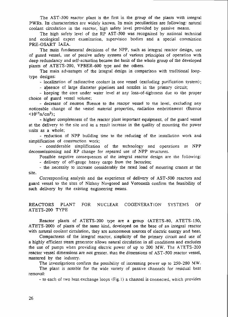
The AST-500 reactor plant is the first in the group of the plants with integralPWRs. Its characteristics are widely known. Its main peculiarities are following: naturalcoolant circulation in the reactor, high safety level provided by passive means.
The high safety level of the RP AST-500 was recognized by national technicaland ecological expert examination, supervision bodies and a special commissionPRE-OSART IAEA.
The main fundamental decisions of the NPP, such as integral reactor design, useof guard vessel, use of passive safety systems of various principles of operation withdeep redundancy and self-actuation became the basis of the whole group of the developedplants of ATETS-200, VPBER-600 type and the others.
The main advantages of the integral design in comparison with traditional loop-type designs:
- localization of radioactive coolant in one vessel (excluding purification system);- absence of large diameter pipelines and nozzles in the primary circuit;- keeping the core under water level at any loss-of-tightness due to the proper
choice of guard vessel volume;- decrease of neutron fluence to the reactor vessel to the level, excluding any
noticeable change of the vessel material properties, radiation embrirtlement (fluence<1017n/cm2);
- higher completeness of the reactor plant important equipment, of the guard vesselat the delivery to the site and as a result increase in the quality of mounting the powerunits as a whole;
- reduction of NPP building time to the reducing of the installation work andsimplification of construction work;
- considerable simplification of the technology and operations at NPPdecommissioning and RP change for repeated use of NPP structures.
Possible negative consequences of the integral reactor design are the following:- delivery of off-gauge heavy cargo from the factories;- the necessity to increase considerably the rated load of mounting cranes at the
site.Corresponding analysis and the experience of delivery of AST-500 reactors and
guard vessel to the sites of Nizhny Novgorod and Voronezh confirm the feasibility ofsuch delivery by the existing engineering means.
REACTORS PLANT FOR NUCLEAR COGENERATION SYSTEMS OFATETS-200 TYPE
Reactor plants of ATETS-200 type are a group (ATETS-80, ATETS-150,ATETS-200) of plants of the same kind, developed on the base of an integral reactorwith natural coolant circulation, they are autonomous sources of electric energy and heat.
Compactness of the integral reactor, simplicity of the primary circuit and use ofa highly efficient steam generator allows natural circulation in all conditions and excludesthe use of pumps when providing electric power of up to 200 MW. The ATETS-200reactor vessel dimensions are not greater, than the dimensions of AST-500 reactor vessel,mastered by the industry.
The investigations confirm the possibility of increasing power up to 250-280 MW.The plant is notable for the wide variety of passive channels for residual heat
removal:- to each of two heat exchange loops (Fig.l) a channel is connected, which provides
26

ATETS-200 reactor plant flow diagram
Containment
Passive self-actuatedRHR channel
Makeup and boroninjection systeirix.
Purification system
'-' -, ^ exchanger
Air heat exchaneer
ERHRS heat
Emergency injectionsystem
Reactor
Fig.l
27

ERHR channelon the Reactor Upper head
Water inventory in ERHR tank - 150 m3
Cooldown diration (grace period) - 24 hrs
The channel self actuates at the reactor pressureincrease up to 21"1"1 MPa
Fig.2
28

residual heat removal through SG with natural circulation with heat removal to watertanks, from where water is evaporated to atmosphere;
- independent passive channel of heat removal (Fig.2) is located on the reactor.With its help primary circuit heat is transferred through the wall of the condenser-heatexchanger by natural circulation to a water tank and then it is removed to atmosphere.
Self-actuation of ERHRS channels with emergency protection actuation and, ifnecessary, of actuations of location system with use of self-actuation devices is provided.
VPBER-600 REACTOR PLANT
An integral reactor with forced coolant circulation at emergency power leveloperation and natural circulation for residual heat removal is used in the design of theVPBER-600 reactor plant for the power unit of a new generation NPP of 640 MW(el)power.
Forced coolant circulation is provided with the help of six leak-tight circulationelectric pumps, located on the bottom of the reactor vessel.
In the design of some equipment and systems the decisions have been mode whichhave been verified by long experience of operation of the existing nuclear power plants.
Calculation analysis of the wide range of accidents, performed on the base of bothdeterministic and probabilistic approaches demonstrated the high safety of the plant. Safetyin the course of three days is provided by passive means without power supply fromoutside nor personnel intervention.
Form the point of view of a deterministic approach for severe core damage, multiplefailures of safety systems elements and systems as a whole are necessary. The probabilityof severe damage to the core, evaluated deliberately conservativelyis < 10"8 per reactor/year.
Nevertheless the search for design decisions for optimization of the reactor designand improvement of characteristics including safety provision for severe accident-accidentswith postulated melting of the core continues.
As a result circulation pumps were moved from the bottom to the cylindrical partof the reactor vessel, reactor internal heat exchangers of the system for emergency heatremoval were excluded, engineering decisions for the Limitation of the consequences ofsevere accident were proposed and the possibility of corium confinement in the reactorvessel or guard vessel was shown.
Moving the circulation pumps to the cylindrical part of the vessel simplifies theoperational servicing of the reactor, excludes the possibility of coolant leakage belowthe core and improves the conditions for corium confinement in the core and in thereactor vessel and for creation of an in-reactor corium catcher.
The schematic diagram of the system of severe accident localization, presented inFig. 3, includes:
- heat exchangers-condensers, of the system of purification and boric reactivitycompensation, total power 10 MW are located in the guard vessel;
- two safety complexes (DN 100), each consisting of a membrane-rupture deviceand a safety valve in series;
- two temperature-actuated devices for the reactor pressure relief;- bubbler of approximately 300 m3 volume;- receivers of 600-700 m3 volume.The bubbler and receivers have the same strength as the guard vessel. In a severe
accident with core melting when the temperature in the reactor reaches 500-700°C, safe
29

SYSTEM OF SEVERE ACCIDENTS LOCALIZTION
on and bone r*aeu
PurtlfleaUon intern
Fig. 3
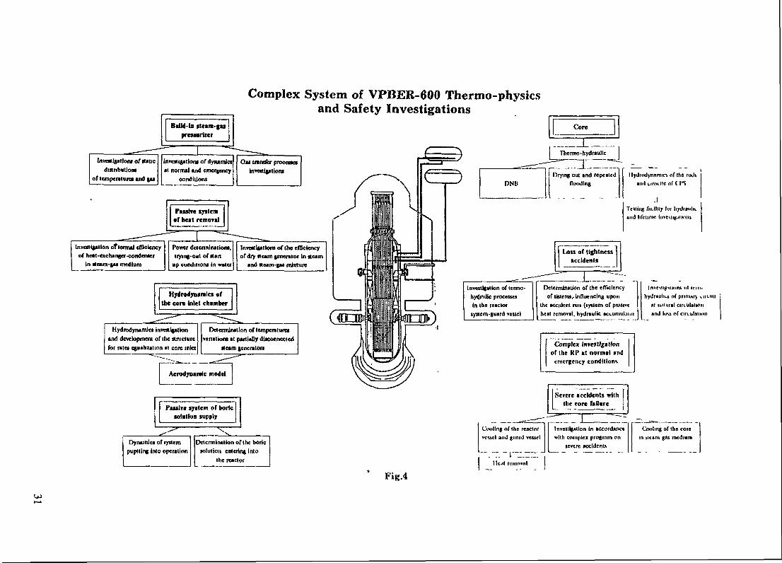
Complex System of VPBER-600 Thermo-physicsand Safety Investigations
^-————'Investigation oTlermal efficiencyof heat-exchanger-condenaer
In steam-gai medium
Passive systemof heat removal
" 1 —— -Power determinations,Irying-out of start
up conditions in water
^- — _Invailgailoni of the eiDelencyof dry fleam generator In Beam
and Mum-gM mixture
Hydrodynamics oftoe core Inlet chamber
Hydrodynamics investigationand development of the structurefor raid equalization at core inlet
Determination of lempenlureavariation* at partially disconnected
•team generator!
Aerodynamic model
Faxslre system of boricsolution supply
Dynamics of fyricmpuptling Into operation
Determination of the boricsolution entering into
Ihe reactor
Fig.4
DNB
InvesUgallon of lermo-hyitnUlc processesIn the reactor
system-guard vessel
j Core 1Thermo-hydraullc
Drying out and repealedflooding
I lydrixlynimiicv of Ihe rvxliunit tit.vv.lte of C I*S
Telling fiiittny fur liyjraulh.and lifclinie invesdg.ilioiu
Determination of the elTiclcncyof sblems, influencing upon
the accident run (system of piusivcheal removal, hydraulic acciimubiot
InvcMtitiiions nl i r i i nhydrauliu of pnmnr) i
at lulural cirLUlalionmt lovi nrciKiilAli
Complex InrfStlgttlonof Ihe Kl> it normal and
emergency conditions
Severe accidents withthe core failure
Cooling of Ihe reactorvcucl and (mud vessel
"~.~7. ~ I—' —~ 'I leal rcmovnl
Invesllgnilon In accordancewllh complex progr.im on
severe accidents
Cooling of Ihe corein Meant gas medium

temperature devices of the reactor are opened and steam-gas mixture is discharged fromthe reactor to the guard vessel, untilpressure is equalized in the guard vessel and thereactor. When pressure hi the guard vessel is 5.0 MPa a membrane-rupture device onthe guard vessel is broken, a safety valve is opened and steam-gas mixture is dischargedfrom the guard vessel to the bubbler. Gases liberated in core melting are pressed outto receivers, this passively solves the problem of provision for hydrogen safety.
Heat removal from the reactor vessel when corium is confined in the reactor orfrom the guard vessel false bottom when corium is confined in the guard vessel if itleaves the reactor vessel is performed with the help of heat exchangers-condensers inthe guard vessel of the purification system.
In normal operation heat exchangers in the guard vessel of the purification systemare disconnected from heat exchangers unit by the pipeline for water supply and areconnected remotely by the operator in the event of severe accident.
CALCULATION AND EXPERIMENTAL JUSTIFICATION OF DESIGN DECISIONSOF INTEGRAL REACTORS
Integral reactors, developed in OKBM, being one of the varieties of PWR, arebased on the common research and development work and on the experience in thecreation, operation and development of such reactors.
But the novelty of the design decisions, connected with the integral lay-out of thereactor, the presence of a steam-gas pressurizer and guard vessel, the absence ofcirculation loops in the circuit and some others, demands special research work to beperformed.
A lot of research work, connected with the experimental study of thermo-hydraulicprocesses in integral PWRs with a built-in steam-gas pressurizer have been performedin the existing experimental base.
The experimental investigations performed confirmed the main design decisions forequipment and systems and allowed substantion of the correctness of the chosen regimeparameters, reliability and safety of the plant.
Together with the problems of the study of thermo-hydraulic processes, occuringin the plant in emergency conditions and of substantiation of the operability and efficiencyof the provided safety systems, the most important problem for the experiments is tocollect representative information for computer code verification.
The main investigations, which are being performed at present are the following:- investigations of DNB in fuel assemblies and temperature state of fuel elements
at partial and complete dry-out of the core;- investigation of the conditions of steam condensation from steam-gas mixture in
the heat exchangers-condensers of the emergency residual heat removal systems and inthe built-in steam generators;
- investigations of steam-gas mixture distribution inside the pressurizer;- investigations of water-gas and chemical conditions in the primary circuit, including
gas transfer in the circuit;- investigations at integral facilities, including a wide range of emergency conditions
with primary circuit loss of tightness and heat removal disruption;- investigations, verifying thermo-hydraulic and lifetime characteristics of steam
generators.Fig.4 shows the complex of facilities for thermo-physical investigations and safety
of VPBER-600.
32

To verify the results on the problem of corium confinement, it is necessary to performadditional investigations into tnermo-physical, physico-chemical and thermo-mechanicalprocesses, to improve calculation modes and computer programs. Besides, theconservativeness of assumptions made considerably compensates for the lack ofinformation and gives every reason to obtain a positive solution of the problem of coriumconfinement in the reactor vessel or guard vessel.
Now testing facility for an integral PWR of 200 MW power is being made readyfor putting into operation.
MAINTENANCE OF INTEGRAL REACTORS(EXAMINATION, REPAIR, DIAGNOSTICS)
The scope and contents of the procedures for maintenance of integral reactors,developed in OKBM meet the requirements of national regulatory documentation. Therebythe following peculiarities of the integral reactor are taken into account:
- presence of the guard vessel;- location of steam-generators (heat exchangers) in the reactor vessel.A complex of special devices for scheduled servicing and, if necessary, for repair
and reconditioning work which account for the peculiarities of integral reactor lay-outhas been developed and tested in AST-500 reactor conditions.
As for inspection of metal and welded joints the following measures are providedin the design:
- periodic visual inspection with video recording of the part of the reactor vesselvisible in the zones between heat exchangers with the help of a periscope and of thewhole surface when the heat exchangers (SG) are removed;
- periodic eddy current and ultrasonic inspection of the welding and main metalof the reactor vessel in the core zone:
- periodic outside visual and ultrasonic inspction of the reactor vessel with the helpof a rotational device and a universal self-propelled device;
- periodic radiographic inspection of the welds of nozzles and penetrations in theupper part of the reactor;
- periodic inspection of the main metal and welds of the reactor vessel using testsample;
- periodic visual inspection of the state of in-vessel devices on removal from thereactor.
The strength and leak-tightness of the structures is confirmed by:- periodic hydraulic tests of the reactor and heat exchangers of the primary and
secondary circuits (steam generators);- periodic pneumatic tests of the guard vessel.In RP power operation, constant control monitoring of the reactor and guard vessel
leak-tightness is provided by measuring the GV environment parameters (pressure, activity,gas content), also acoustic-emission methods of inspection are used.
Constant monitoring of primary-secondary circuit heat exchanger (SG) leak-tightness at RP power operation is performed by measuring the activity and gas contentof the secondary circuit medium.
In the event of heat exchanger (SG) loss of tightness the leaking section is lookedfor, the leaking part is plugged or (if necessary) the whole section is substituted withthe help of special devices.
Analysis and discussion of the decisions made by operating staff experts have showntheir acceptability during operation.
33
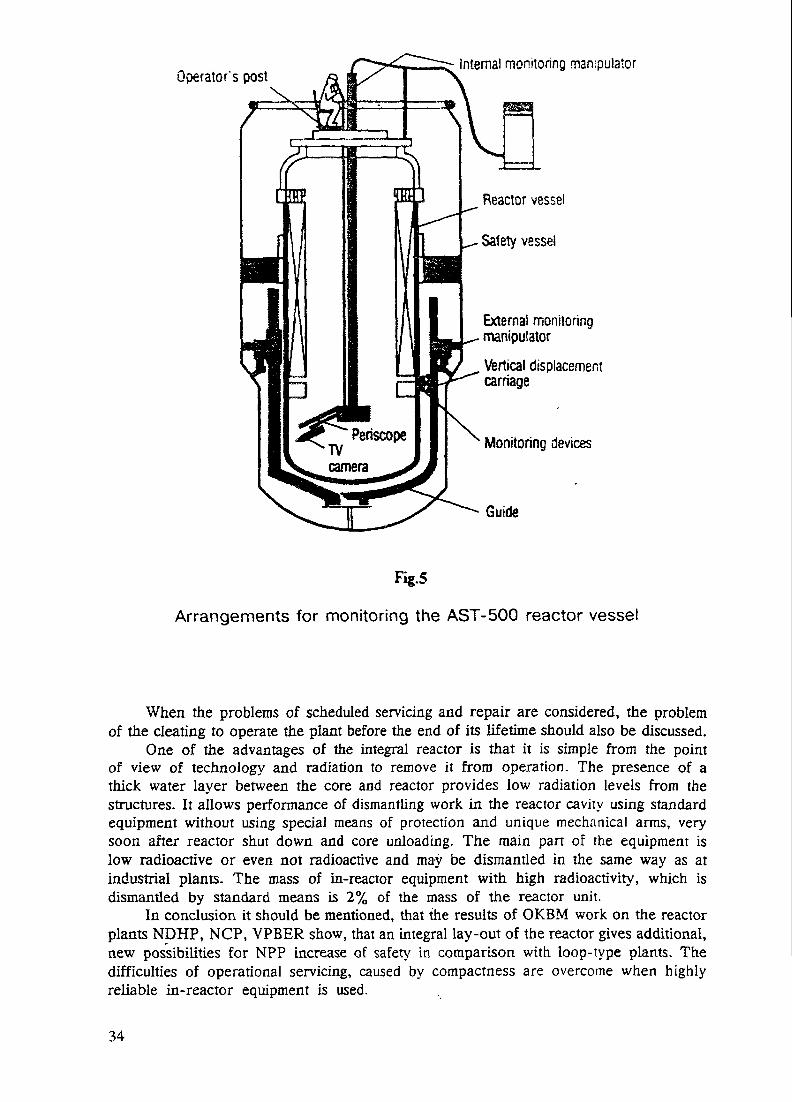
Operator's postInternal monitoring manipulator
Reactor vessel
Safety vessel
External monitoringmanipulator
Vertical displacementcarnage
Monitoring devices
Guide
Fig.5
Arrangements for monitoring the AST-500 reactor vessel
When the problems of scheduled servicing and repair are considered, the problemof the cleating to operate the plant before the end of its lifetime should also be discussed.
One of the advantages of the integral reactor is that it is simple from the pointof view of technology and radiation to remove it from operation. The presence of athick water layer between the core and reactor provides low radiation levels from thestructures. It allows performance of dismantling work in the reactor cavity using standardequipment without using special means of protection and unique mechanical arms, verysoon after reactor shut down and core unloading. The main pan of the equipment islow radioactive or even not radioactive and may be dismantled in the same way as atindustrial plants. The mass of in-reactor equipment with high radioactivity, which isdismantled by standard means is 2% of the mass of the reactor unit.
In conclusion it should be mentioned, that the results of OKBM work on the reactorplants NDHP, NCP, VPBER show, that an integral lay-out of the reactor gives additional,new possibilities for NPP increase of safety in comparison with loop-type plants. Thedifficulties of operational servicing, caused by compactness are overcome when highlyreliable in-reactor equipment is used.
34

REACTOR TYPE CHOICE AND CHARACTERISTICS XA9745971FOR A SMALL NUCLEAR HEAT ANDELECTRICITY CO-GENERATION PLANT
LIU KUKUI, LI MANCHANG, TANG CHUANBAONuclear Power Institute of China,Chengdu, Sichuan Province,China
Abstract
In China, heat supply consumes more than 70 percent of the primary energy resource, which makesfor heavy traffic and transportation and produces a lot of polluting materials such as NO,, SO, and CO2
because of use of the fossil fuel The utilization of nuclear power into the heat and electricityco-generation plant contributes to the global environmental protection.
The basic concept of the nuclear system is an integral type reactor with three circuits. The primarycircuit equipment is enclosed in and linked up directly with reactor vessel. The third circuit producessteam for heat and electricity supply. This paper presents basic requirements, reactor type choice,design characteristics, economy for a nuclear co-generation plant and its future application.
The choice of the main parameters and the main technological process is the key problem of thenuclear plant design. To make this paper clearer, take for example a double-reactor plant of 450 x2MW thermal power. There are two sorts of main technological processes. One is a water-water-steamprocess. Another is water-steam-steam process. Compared the two sorts, the design which adopted thewater-water-steam technological process has much more advantage. The system is simplified, theoperation reliability is increased, the primary pressure reduces a lot, the temperature differencebetween the secondary and the third circuits becomes larger, so the size and capacity of the maincomponents will be smaller, the scale and the cost of the building will be cut down.' In this design, thesecondary circuit pressure is the highest among that of the three circuits. So the primary circuitradioactivity can not leak into the third circuit in case of accidents.
keywordssmall-sized nuclear co-generation, integral, self-pressurized, forced circulation, water-water-steamtechnological process
1 IntroductionWith the development of human society, more and more heat supply is needed . The heat supply
consumes more than 70 percent primary energy resource in China, while the electric power supplyconsumes only about 20 percent of the resource. It not only uses up about more than 4 x 10' tons coalevery year, but also burns a great quantity of oil, which makes for heavy traffic and transportation , andcauses environmental pollution and unnecessary resource waste. It is a good idea to construct a batch ofnuclear co-generation plants near to the cities where the steam and heat supply is centralized in thefuture. This is a new way to save energy, relax traffic and transportation and reduce environmentpollution.
35

The development of nuclear co-generation plant is a possile of prospective economical way, but howto ensure that the small-sized plant clean, safe and cheap is the first problem to be considered by thedesigners. Based on previous design experience, the plant design objectives are put forward as follows:
(1) Low basic capital investment The specific cost of the plant should be less than 750 $/KW;(2) Construction period: A single-reactor plant needs about 5 years and a double-reactor plant needs
about 6 years;(3) Operational reliability: The availability is up to about 85%-90% and the load factor is more than
80%;(4) No large pipe break accidents (all the plant pipe diameters are less than 100mm) and no LOCA in
the primary circuit The reactor melt probability is less than 10~Vreactor-year. The reactor can be cooledusing its own resources and the storage battery sources when normal onsite and offsite electric power islost The plant can be built in a nsely-populated area because of the reactor's passive safety and highreliability;
(5) Being simplified in system, compacted in layout and of small constructive scale;(6) Because the high and large reactor building is cancelled and the foundation loading is lightened,
the plant can be built in seabeach, soft soil, seismic areas and so on. On the plant site choice, it is similarto the fossil-fueled power plant;
(7) The heated steam for heat supply has no radioactivity and its radiation level almost equals that ofnatural radiological reference state;
(8) The reactor building is pressurized and airtight The environment around the plant would not bepolluted in case of radioactive leakage.
2 Reactor type choice for nuclear co-generation plantThe base of reactor type choice is whether it will meet the above-mentioned design objectives,
technology reality and feasibility and users requirements' or notPressurized water reactors (PWR), boiling water reactors (BWR) and high temperature gas-cooled
reactors (HTGR) can all be used as the co-generation plant Comparing with the other types of reactors,for PWR there is a lot of experience in experiment, research, design, manufacture, installation andoperation in China.
The steam supply parameters are also the base of reactor type choice. According to the steamparameters which a few large Chinese technological process users need at present, the majority is steamin the middle or in low pressure. From an application of view, PWR and BWR can all meet users'requirements. The primary circuit pressure of a BWR is usually 6.86MPa. Its core outlet temperature is285 <c , while usually the core outlet temperature of a PWR can reach 310-325 "C which can producemedium pressure steam in the third circuit The PWR has a larger application range than the BWR.
In summary, a PWR should be chosen as the nuclear co-generation plant in China, and the steamsupply capacity is usually no more than lOOOt/h, so the single-reactor thermal power will not be morethan 600MW. A double-reactor in a plant would be better suited to our conditions in which heat andelectricity are supplied at the same time and how much the electricity will be produced is based on howmuch the steam is consumed.
36

Figure 1 Main System Diagram or Nuclear Thermal Power Plant1.reactor2.steam generator3.Bain coolant pump4.presaurlzer5. lafety hjeetle* tMkfi.rollof tonic7<volumo cunlrol tonicfl.charging pump9.rosin bod1 0.containment nunip
11.residual heat removal pumpIZ.aafety injootion pumpt 3.spray pump14.refueling water tankI5.iilgh preaaure turbine16.low proa aura turbln*
21.low preeaure heater22.naln feed water punp27.lU.gh pressure deaerator24.hi^b pressure heater25.storage tank26.pressurizing punp
17.moisture separator and rehoater27.1ov pressure evapratorlO.condanaer 2Q.nediura pressure evaprator
29.low pressure deaerator30.eleotrlo reagnetlo flllar
19.iiydrogen ion onohnn^or20.uixoil bod
5l..nlic.l hod 32.mice up wntor for third circuitU.to Imron rccvclo .ovatpm 33.uontainraent

OJoo
f n LVr-M-vl\—vy
Figure 2 Small Sized Nuclear Co-generation PlantThermal-hydraulic System Flow Diagram

INTEGRATED PVfR COMMON DRAWING
J. 7lliJU JtUQIJ)i 2. reactor core
rrictor lesieJ4. htil nctnanr5. CXOKI. itconi aide tiler inlet7. second side nl;r outltl
39

3 Summary of the small-sized nuclear co-generation plant designA 450 MW nuclear co-generation plant will be considered as an example in this paper. In order to
simplify the system, reduce the construction scale and the cost of the plant, an integralself-pressure-stabalized water reactor is adopted.
3.1 Main parameters and main technological processThe Choice of the main parameters and the main technological process is the key problem of the
nuclear co-generation plant design. In conventional consideration, the original design of the plant ofShanghai Jinshan General Petro-chemical Works adopted the water-steam-steam technological process.( figure 1). The normal operation pressure of the main coolant is ISMPa. The middle circuit steampressure is SMPa. The third circuit produces 75t/h steam at pressure 4MPa , 320t/h saturated steam atpressure 1.6MPa and electric capacity 52000KW (the above-mentioned is single-reactor).
The disadvantage of this technological process is as follows:(l)Radioactivity would be carried into the third circuit steam in case of failure of the heat
exchangers, a detection system and the necessary emergency provisions must be set up;(2) The efficiency of the steam-steam heat exchanger is very low, so the number of the exchangers is
large (9 heat exchangers needed in one reactor), and the building area is large;(3) More makeup water pre-beat exchangers are needed in the third circuit and therefore cause a
very high cost.
According to the experience in the water-steam-steam technological process and in order to ensurethe non-radioactive steam to be supplied, the three circuits systems are still adopted in the nuclearco-generation plant. In order to simplify the system, reduce the equipments size, and ensure operationreliability and passive safety, the water-water-steam technological process is adopted in the steamsupply, its main parameters and principle flow diagram are shown in figure 2.
The base to choose operating pressure and temperature of the three circuits is:(1)To ensure that 3.92MPa saturated steam in the third circuit would be produced;(2) To balance the heat exchangers size between the primary and the secondary circuits.
The main coolant pressure adopted lOMPa. Because the reactor adopts self-pressure-stabalizedoperation, the core outlet temperature is 309.51, the core inlet temperature is 289.5% and the coolantflow is 14,000t/h.
The middle circuit coolant (water) pressure, which is the highest among the three circuits, islO.SMPa. So the primary circuit radioactivity cannot leak into the third circuit
The middle circuit can adopt two, three or four loops. In this paper two loops are adopted. The totalcircuit flow is 15,000t/h, and its main pump is a wet-stator pump. Its hot leg temperature is 2801; andcold leg temperature is 258.5% .
The third circuit steam pressure is 4 MPa. It adopts U-type SGs. The heat transfer area of each SG is2666.5m2 and its design area is 3066.5m2. The margin is 15%.
The majority of pipes and valves in the secondary and the third circuit are manufactured from lowalloy steel and carbon steel.
A comparison of the effects of water-water-steam and water-steam-steam technological process onthe heat transfer is shown in table 1. While keeping the steam temperature in the third circuit at thesame level, this design has these main advantages:
40
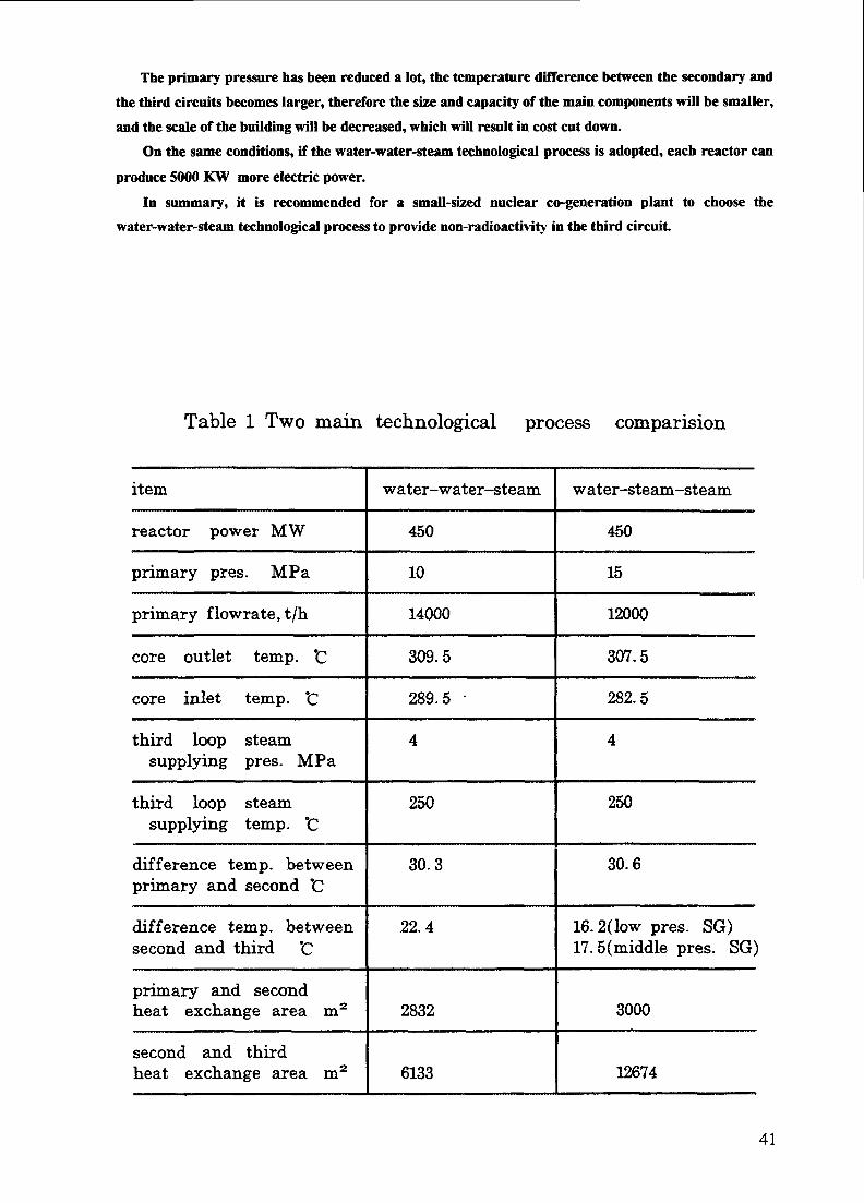
The primary pressure has been reduced a lot, the temperature difference between the secondary andthe third circuits becomes larger, therefore the size and capacity of the main components will be smaller,and the scale of the building will be decreased, which will result in cost cut down.
On the same conditions, if the water-water-steam technological process is adopted, each reactor canproduce 5000 KW more electric power.
In summary, it is recommended for a small-sized nuclear co-generation plant to choose thewater-water-steam technological process to provide non-radioactivity in the third circuit.
Table 1 Two main technological process comparision
item
reactor power MW
primary pres. MPa
primary flowrate, t/h
core outlet temp. *C
core inlet temp. "C
third loop steamsupplying pres. MPa
third loop steamsupplying temp. *C
difference temp, betweenprimary and second *C
difference temp, betweensecond and third "C
primary and secondheat exchange area m2
second and thirdheat exchange area m2
water-water-steam
450
10
14000
309.5
289.5 •
4
250
30.3
22.4
2832
6133
water-steam-steam
450
15
12000
307.5
282.5
4
250
30.6
16.2(low pres. SG)17. 5( middle pres. SG)
3000
12674
41
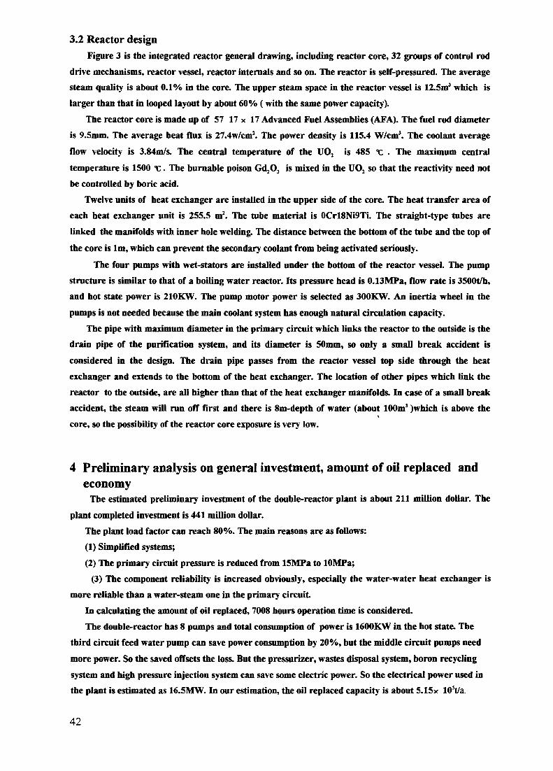
3.2 Reactor designFigure 3 is the integrated reactor general drawing, including reactor core, 32 groups of control rod
drive mechanisms, reactor vessel, reactor internals and so on. The reactor is self-pressured. The averagesteam quality is about 0.1% in the core. The upper steam space in the reactor vessel is 12.5mJ which islarger than that in looped layout by about 60% (with the same power capacity).
The reactor core is made up of 57 17 x 17 Advanced Fuel Assemblies (AFA). The fuel rod diameteris 9.5mm. The average heat flux is 27.4w/cm2. The power density is 115.4 W/cm3. The coolant average
flow velocity is 3.84m/s. The central temperature of the UO2 is 485 "c . The maximum centraltemperature is 1500 t. The burnable poison Gd,O3 is mixed in the UO2 so that the reactivity need notbe controlled by boric acid.
Twelve units of heat exchanger are installed in the upper side of the core. The heat transfer area ofeach heat exchanger unit is 255.5 m2. The tube material is OCrl8Ni9Ti. The straight-type tubes arelinked the manifolds with inner hole welding. The distance between the bottom of the tube and the top ofthe core is 1m, which can prevent the secondary coolant from being activated seriously.
The four pumps with wet-stators are installed under the bottom of the reactor vessel. The pumpstructure is similar to that of a boiling water reactor. Its pressure head is O.lSMPa, flow rate is 3500t/h,and hot state power is 210KW. The pump motor power is selected as 300KW. An inertia wheel in thepumps is not needed because the main coolant system has enough natural circulation capacity.
The pipe with maximum diameter in the primary circuit which links the reactor to the outside is thedrain pipe of the purification system, and its diameter is 50mm, so only a small break accident isconsidered in the design. The drain pipe passes from the reactor vessel top side through the heatexchanger and extends to the bottom of the heat exchanger. The location of other pipes which link thereactor to the outside, are all higher than that of the heat exchanger manifolds. In case of a small breakaccident, the steam will run off first and there is Sin-depth of water (about 100m3 )which is above the
\
core, so the possibility of the reactor core exposure is very low.
4 Preliminary analysis on general investment, amount of oil replaced andeconomy
The estimated preliminary investment of the double-reactor plant is about 211 million dollar. Theplant completed investment is 441 million dollar.
The plant load factor can reach 80%. The main reasons are as follows:(1) Simplified systems;(2) The primary circuit pressure is reduced from ISMPa to lOMPa;
(3) The component reliability is increased obviously, especially the water-water heat exchanger ismore reliable than a water-steam one in the primary circuit
In calculating the amount of oil replaced, 7008 hours operation time is considered.The double-reactor has 8 pumps and total consumption of power is 1600KW in the hot state. The
third circuit feed water pump can save power consumption by 20%, but the middle circuit pumps needmore power. So the saved offsets the loss. But the pressurizer, wastes disposal system, boron recyclingsystem and high pressure injection system can save some electric power. So the electrical power used inthe plant is estimated as 16.5MW. In our estimation, the oil replaced capacity is about 5.15x 10⁵t/a.
42

The following is a brief plant economic analysis:(1) Electricity and heat co-generation costThe estimated plant operation cost is 23.5 million dollar each year. It produces 0.798 billion KWhr
electricity (about 0.683 billion KW.hr for users), 3558 billion Kcal heat If the price of one million Kcalheat is considered as 2.95 dollar, the heat supply can obtain 10.5 million dollar profit Thus, the grosscost of the electricity is 0.016 doIlar/KW.hr and its net cost is 0.019 doIlar/KW.hr.
(2) Retrieval fundsThe production cost is about 23.5 million dollar, but the cost of the oil which would be replaced
every year, is about 60.6 million dollar. The difference is 37.1 million dollar. The time needed to recovercapital is about 12 years. If the oil price is 176.5 dollar/t, the time is 7 only years.
(3) Thermal efficiencyThe thermal efficiency of a large nuclear power plant is about 33%, while the nuclear co-generation
plant is about 80%.In summary, the small-sized nuclear co-generation plant is more economic than the coal or oil fuel
co-generation plant
5 Design characteristics and its prospects(1) Adopting integrated self-pressurized water reactor.(2) The primary circuit operational state is: the primary coolant is at low pressure; the reactor core
has a low power density; the fuel in low temperature; while the coolant has a high average temperature.So not only the safety but also the economical steam is ensured. The third circuit steam pressure canreach 4MPa and thermal efficiency can come up to about 80% while the primary pressure is only 10MPa.
(3) Adopting a water-water-steam technological process improves the operation reliability of the heatexchangers in the reactor. The middle circuit pressure is higher than the primary's, so radioactivityleakage is prevented from the primary to the third. The size of the heat exchangers and relatedbuildings is reduced.
(4) The reactor and the primary circuit have adoped an adopt integrated layout The inner diameterof the containment is only 16m, so the reactor building is reduced to a minimum and the nuclear islandcovers 2518m2, only 32% that of looped layout
(5) Large amount of concrete and steel will be reduced and the general cost will also be reducedbecause of the small constructive scale. And a half of million tons oil will be replaced every year. So thetime to recover capital is estimated as about 7 years.
(6) High passive safety and reliability. About 20% thermal power can be removed by the naturalcirculation of coolant when the main pumps stop. So a core melt accident will not occur when the mainpump motor electricity is lost It is almost impossibly difficult for radioactivity to leak into the thirdcircuit because of the high pressure in the middle circuit The accident probability drops down becausethe systems are simplified and the number of valves and pumps also decreased. The water-water heatexchanger is more reliable than a steam generator in the reactor. All the above-mentioned can reduce
unexpected plant shutdowns and improve the plant availability.(7) The plant can be built near a city or a large enterprise because of the reactor's high passive safety
and two-layered containment
43

(8) The plant layout is compact and the main and the auxiliary buildings take up less land, and thefoundation loading is lightened. So it is favourable for the plant to be built on seabeach, soft soil or aseismic area.
(9) The main components of the reactor and the primary circuit can be manufactured and installedin the factory. On site installation and examination work become less. The nuclear island constructivescale is small. So the double-reactor constructive period can be shortened to 5 years.
(10) The shape of the main and the auxiliary buildings on the nuclear island is simple, it is easy toconstruct So the construction period is shortened.
Table 2 Main Performance Comparison
No
1
2
3
4
5
6
7
8
9
10
11
12
13
14
15
item
reactor power MW
steam supply capacity t/h
electricity supply capacity KW
thermal efficient %
plant load factor %
replaced oil amount 104 t/a
primary operation pre. MPa
containment dia. inner mouter m
nucl. island land area m2
nucl. island constrution area m2
volume m3
conventional island land area m2
conv. island constrution area m2
volume m3
general investment 10syuan
construction period year
maximum postulated accident
integrated layout
450 x 2
75 x 2 (middle pre.)320 x 2(low pre.)
56947 x 2
- 80
80 '
51. 455
10
1620
2518
20000190000
6000
22800190000
10
5
drain pipe( 4> 50)rupture
looped layout
450 x 2
75 x 2(middle pre.)320 x 2(low pre.)
52000 x 2
79.'15
70
43.6
15
2933.30
7884
23320353185
8522.7
31728229808
13
6-7
main pipe( $150)rupture
44

Table 2 is the main performance comparison between the integrated and the looped pressurizedwater reactor. The parameters in table 2 indicate that this design meets the basic requirements of anuclear co-generation plant
According to the above-mentioned, the small-sized nuclear co-generation plant is economicallycompetitive. Referring to more than twenty users' steam consumption, it is suitable to adopt400-600MWt power for the single-reactor. For the nuclear co-generation plant, its main function is heatsupply, while the amount of electricity supplied depends on how much the heat is supplied. To avoidcausing a high turbine cost, the electric power proportion should not be too large. If the heat supply isthe main function and the electricity supply is auxiliary, the three circuits and water-water-steamtechnological process should be adopted.
For the reactor choice, PWR and BWR have all been considered. But the former is put first to raisethe reactor core temperature, produce medium pressure steam in the third circuit and expand the scopeof steam supply. The reactor and the primary circuit adopt an integrated layout and forced circulation.It is more compact than BWR with natural circulation. It is more suitable that the operation pressure ofthe self-pressurized water reactor adopts lOMPa according to the steam parameter requirements ofdomestic chemical industry.
In accordance with the above discussion, for a small-sized nuclear co-generation plant, conclusionsare made as follows:
(1) Adopt integrated, forced circulation, self-pressure-stabalized water reactor.(2) Reactor operation pressure lOMPa.(3) Single-reactor power 400-600MWt, maximum to lOOOKWt(4)Adopt water-water-steam main technological process and electricity supply depends on steam
supply.(5) No boric acid and simplified system.
This design also suits a small nuclear electric power plant But the heat exchangers should be replacedby steam generators in the reactor vessel.
The design can also be used for centralized heat supply in a city. On condition of not changing thereactor and the auxiliary system, only decreasing operation pressure and temperature, and the steamgenerator being replaced by the heat exchangers in the third circuit, this design would turn to be nuclearheat supply plant, while the research and experiment are not needed furthermore.
Natural circulation and forced circulation should be compared further in the future and the controlrod drive mechanism type needs improving. A core with a high conversion ratio in a small reactor isworth researching further.
In summary, a small nuclear heat and electricity co-generation plant could become an economic, safeand clean energy source in a city or a large enterprise in the future. Its basic capital investment is low,the construction period is short, it has a wide range of uses, it has good prospects and it should have aproper position in the energy resource development of China.
NEXT PAOOfS)left BLAKK
SE3555
45

THE CAREM PROJECT: PRESENT STATUS XA9745972AND DEVELOPMENT ACTIVITIES
H.J. BOADO MAGAN, J.P. ORDONEZINVAP S.E.,San Carlos de Bariloche
A. HEYCNEA,Buenos AiresArgentina
Abstract
The CAREM Project is a low power NPP of 25 Mwe, with an integrated self pressurized primary system The cooling
of the primary system is of the natural circulation type and several passive safety systems are included The owner of the Project
is Argentina s CNEA (Comision Nacional de Energia Atomica) and its associated company, fNVAP, is the main contractor
The present status of the CAREM Project is presented The possible evolution of the CAREM project is mentioned in
relation with a new containment design A short description of the Experimental Facilities, listed below, already in operation and
under construction are also included
• CAPCN High Pressure Loop Natural convection loop to verify dynamic response and critical heat flux
• RA-8 Critical Facility, designed and constructed for the CAREM Project (that may be used as a general uses facility)
• RPV Internals The whole assembly of absorbent rods, connecting rods and the rode guides are being constructed in a 1 1scale The aims of this experimental facility are vibration analysis and manufacturing parameters definitions
• Control Drive Mechanisms A sene of verification and tests are being earned out on these within RPV hydrauhcally driven
mechanisms
Other development activities are mentioned in relation with the thermalhydraulics, Steam Generators and Control
1. CAREM Project Present status.
1.1. IntroductionThe CAREM, a small NPP Project owned by the CNEA /!/ has been developed jointly by CNEA and INVAP 121 The
concept was bom by the 80,s when the idea was presented at LIMA, Peru, during an IAEA conference back in 1984 At thattime, the Argentinean nuclear experience was several RR built (RA-0, RA-I, RA-2, RA-3, RA-6, RP-0) several Projects onRR, an enrichment plant and the experience gained in the follow up of two NPP in operation (CNA-1 and CNE) It was thoughtthat the next step to reach the nuclear maturity should be to work in the design and construction of a NPP This development in amedium size economy and restricted financial resources should have a limited risk and so the focus was addressed to small NPPIn addition the NPP should be able to operate in isolated cities, a common situation in Argentina That meant reduced ability toobtain help in operational incidents/accidents by the operating personnel, reduced industrial/ technical resources in the site, longdistances from fully developed areas, reduced roads and transportation capacities And being the first domestic NPP, it was alsoconsidered convenient to work in an electrical plant with a small output when connected to the national electric network Similarconditions could be find in a good number of countries
The above mentioned crilenum developed m the CAREM technical characteristics i e a LWR, with Integrated PrimarySystem and extensive use of the so called passive systems (e g natural circulation cooling)
Fixed arbitranously the power in 15 Mwe, a R&D program was started and so the construction of a thermalhydrauhclab and a critical facility
At present the work is addressed to the 25 Mwe but a new version of 100 Mwe is also foreseen
1.2. OrganisationCNEA has subcontracted the engineering of the CAREM to INVAP However by itself is working on the development
of the fuel Elements and m part of the nuclear instrumentation The follow up activities on the CAREM Project arc made byCNEA with a Coordination Group which receives all the engineering from INVAP Afterwards the engineering enter in arevision process inside the CNEA by groups specially appointed by the CAREM Coordinator Every three months theCoordination Group have a meeting with their counterparts in INVAP were technical discussions arc held Also visit andrevisions of the experiment works are done In some especial topics as RPV design and manufacturing, foreign experts areinvited to assist and make special revisions Experts from other companies are also sometime required
47

1.3. Engineering StageThe CAREM Project is under the development of the Detail Engineering needed to start the construction A technical
revision was made by the owner of the project (CNEA) in 1992 and a cost estimation following TRF 269 was finished in 1993During the present year the main tasks were devoted to work on those subjects with lack of experience and were
research and development were needed as RPV Containment, Internals, Thermal hydraulics of different Systems (RPV,Secondary, Primary, Containment etc) lay-out This in depth studies encourage the Project Personnel to study differentsolutions for the containment and RPV From the left to the nght in the next picture we have the previous design and the one inwhich studies are done at present The "old" design has a containment made totally with steel and the RPV with a conical shapeThe design was originally aimed to have a modular containment which could be transported in big pieces in order to reduce theon site works However, the solution suggested for the fixation of the containment was a difficult one from the point of view ofcivil engineers Because of the reduced containment size it was necessary to have the conical shape (small space for the RPVhead) The latest design made from concrete in its lower part allow to have bigger available spaces so the RPV is of the straighttype This solution increases the maintainability of the NPP, mainly the SG are more available for repairs, one of the weak pointsin the "old' The more available space allow us to change the SG feeding pipes from a downwards type to a horizontal whichpermits an easier manufacturing solution Up to today the only drawback of the latest design is the corresponding to the dnvemechanisms support which now is positioned m a bigger cylinder
In the following sections a short description of the activities in process except for those related to the SG in theCAREM Project are mentioned In relation with the SG, a Special Program is been conducted That Program has started withthe construction of a mini SG to be tested in a high pressure loop Studies are underway to define the whole scope of data thatshould be obtained from a 1 1 model The studies include the qualification process and the search of a facility for testing the SG
2. CAPCN (Circuito de Alta Preston y Convection Natural): High Pressure Loop.
2.1. Description and Similarities with CAREM-25The High Pressure Natural Convection Loop is part of the Thermal Hydraulics Laboratory Designed, Constructed and
operated by INVAP for the CNEA Its purposes are to verify the thermal hydraulic engineering of CAREM NPP mainly on twosubjects dynamic response and critical heat flux These are accomplished by the validation of the calculation procedures andcodes for the ng working in states corresponding (by similarity criteria) to the operating states of CAREM reactor
CAPCN resembles CAREM in the primary loop, while the secondary loop is designed just to produce adequateboundary conditions for the heat exchanger Operational parameters are reproduced approximately for intensive magnitudes(Pressures, temperatures, void fractions heat flux etc) and scaled for extensive magnitudes (flow, heating power, size, etc)Height was kept in a I I scale
48
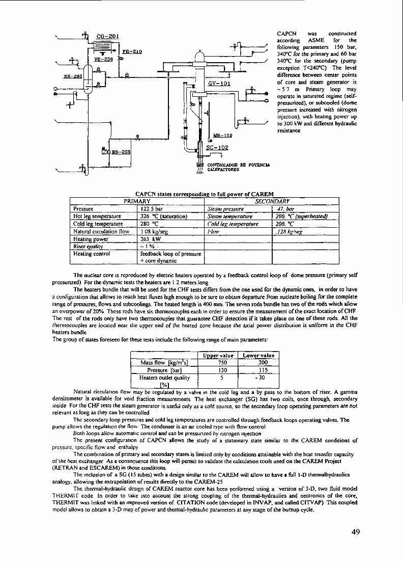
CAPCN was constructedaccording ASME for thefollowing parameters ISO bar,340°C for the primary and 60 bar340°C for the secondary (pumpexception T<240°C) The leveldifference between center pointsof core and steam generator is- 5 7 m Primary loop mayoperate in saturated regime (self-pressurized), or subcooled (domepressure increased with nitrogeninjection), with heating power upto 300 kW and different hydraulicresistance
CONTROLADOR DE POTENCUCALEPACTORES
CAPCN states corresponding to full power of CAREMPRIMARY
PressureHot leg temperatureCold leg temperatureNatural circulation flowHeating powerRiser qualityHeating control
122 5 bar326 °C (saturation)280 °C1 08 kg/sej;263 kW~ 1 % -feedback loop of pressure+ core dynamic
SECONDARYSteam pressureSteam temperatureCold leg temperatureI- low
47. bar290. "C (superheated)200. "C.128kj>'seK
The nuclear core is reproduced by electric heaters operated by a feedback control loop of dome pressure (primary selfpressurized) For the dynamic tests the heaters are 1 2 meters long
The heaters bundle that will be used for the CHF tests differs from the one used for the dynamic ones, in order to havea configuration thai allows to reach heat fluxes high enough to be sure to obtain departure from nucleate boiling for the completerange of pressures, flows and subcoolings. The heated length is 400 mm. The seven rods bundle has two of the rods which allowan overpower of 20% These rods have six thermocouples each in order to ensure the measurement of the exact location of CHFThe rest of the rods only have two thermocouples that guarantee CHF detection if it takes place on One of these rods. All thethermocouples are located near the upper end of the heated zone because the axial power distribution is uniform in the CHFheaters bundleThe group of states foreseen for these tests include the following range of main parameters1
Mass flow [kg/m2s]Pressure [bar]
Heaters outlet quality[%1
Upper value7501305
Lower value200115
-30
Natural circulation flow may be regulated by a valve in the cold leg and a by pass to the bottom of riser. A gammadensitometer is available for void fraction measurements The heat exchanger (SO) has two coils, once through, secondaryinside For the CHF lests the steam generator is useful only as a cold source, so the secondary loop operating parameters are notrelevant as long as they can be controlled
The secondary loop pressures and cold leg temperatures are controlled through feedback loops operating valves. Thepump allows the regulation the flow The condenser is an air cooled type with flow control
Both loops allow automatic control and can be pressurized by nitrogen injectionThe present configuration of CAPCN allows the study of a stationary state similar to the CAREM conditions of
pressure, specific flow and enthalpyThe combination of primary and secondary states is limited only by conditions attainable with the heat transfer capacity
of (he heat exchanger As a consequence this loop will permit to validate the calculation tools used on the CAREM Project(RETRAN and ESCAREM) in those conditions.
The inclusion of a SG (15 tubes) with a design similar to the CAREM will allow to have a full 1-D thermalhydraulicsanalogy, allowing the extrapolation of results directly to the CAREM-25
The thermal-hydraulic design of CAREM reactor core has been performed using a version of 3-D, two fluid modelTHERM IF code In order to take into account the strong coupling of the thermal-hydraulics and neutronics of the core,THERMIT was linked with an improved version of CITATION code (developed in INVAP, and called CITVAP) This coupledmodel allows to obtain a 3-D map of power and thermal-hydraulic parameters at any stage of the bumup cycle.
49
The thermal limits were calculated using the 1986 AECL-UO Critical Heat Flux Lookup Table, validated till now withall the available measurements in the operational range in order to ensure a 95/95 reliability/confidence in the thermal limit. TheCAPCN CHF test results will be used to improve these calculations by increasing the experimental data in the operating rangeand fuel element geometry of the CAREM core.
2.2. Experimental ProgramThe Program is divided in two main subjects
Dynamic Tests/3/In order to reduce the range of experiments it was defined that the studies will be limited to the regimes, states and
perturbations foreseen for the CAREM 25. The studies will be limited to those parameters included in the modelling by computercodes.
Several conditions were established:• The primary subcooled state is relevant only during the start up of the CAREM• The existence of secondary subcooled and saturated states will depend on the method adopted for the start up. The situation
can be avoided if there is steam available."• Nitrogen in the dome will be limited up to 30 Kg/cm2.• Possible perturbations in the Primary Side are produced by neutronic changes and power extraction form the secondary side.Parameters of interest areithermal balances; water flow; thermal transference coefficients in SG, dome, and void fractions in theriser; Primary and secondary pressure and temperature; dome volume; hydraulic drag; neutron kinetics.This stage of experiments is at present underway and will be finished by march of next year.
CHF Tests /4/, /5/ and /6/It is known that to perform reliable thermalhydraulic calculations it is necessary to perform CHF experiments for the
start up and nominal power states. In this case the CAPCN will be used with some modifications in the control system in order toobtain stable values for the pressure, water flow, water quality, with a positive power ramp. Part of the experimental work to bestarted next year will be devoted to determine limits and operational conditions for the CHF experiments. A detailed study wasalready done with the corresponding Program. For the CHF experiments themselves it was necessary to make carefull studiesbecause it was not possible to install a section of the same dimensions as for CAREM Fuel Element. Variables kept as inCAREM are rod diameter, pitch and ratio total section/water flow section. Preliminary experiments for temperature oscillationsdue to slug flow patterns will be made before starting the CHF experiments.
2.3. Start-up and experimental resultsThe phases accomplished for the Start-Up Program are:• Hydraulics characterisation, cold state.• Primary isolated: selfpresurization test, control loops calibration. Degasification of primary side• Whole system operation. Secondary side in liquid phase. Initial calibration of condensed tank control loops in temperature
and flow. Thermal balance.• Whole system operation. Operating regime at low power with overheated steam and automatic control.
At present the following results has been obtained:
Self prcssurization in the operating range of CAREM-25 with natural convection was confirmed.The Thermalhydraulic Process was controlled during the different power conditions without major problemsThe production of over-heated steam is compatible with the CAREM operating conditions.Considering the loop as an experimental machine the following experience has been obtained:The Data Acquisition and Control System has fulfilled its required performance. However, some problems related with hardwarecharacteristics aroused: temperature were measured with an accuracy lower than required. An interface between the DACS andthe sensors was frequently in needs of recalibration. They are already replaced and a safety controller was added to theSupervision System Some improvements were made: New Fuel Assembly spacer (CAREM design) in order to make a durabilitytest of this component; new measurements in the heat exchanger and new improvements in the valves used for control. Somemodification in the condenser design were also needed to reach the full power state (300 Kw of electrical heat). In order toreduced the experimental errors several data will be also recorded through a new interfase, with a lower error and frequency ofcalibration needs. Improvements in the thermal isolation were also done.
3. RA-8.Crirical Facility.3.1 Description
The RA-8 critical assembly has been designed and constructed as an experimental facility to measure neutronicparameters of the CAREM NPP, under contract and supervision of the National Atomic Energy Commission (CNEA) ofArgentina. It may be used, with relatively minor changes, as a facility to perform experiments for other light water reactors. Itprovides a reactor shielding block and reactor tanks that can be adapted to hold custom designed reactor cores.
The RA-8 critical facility is located in the PILCA IV Sector of the PILCANIYEU TECHNOLOGICAL COMPLEX, inthe Province of Rio Negro, Argentina, at approximately 30 km East of San Carlos de Bariloche. It occupies the main hall of abuilding shared with the Laboratory for Thermalhydraulic Tests (LET), described in Section 2 of this report, and other specialfacilities for CAREM Project Geometry and location of core shielding inside the main hall are such that radiation dose levels areacceptable in adjacent rooms, for all operational conditions.
50

General Characteristics of the RA-8, are:Low operating power, which makes cooling systems unnecessary.Extinction systems.
Rapid insertion of control rodsDumping of the moderator
Regulation and safety rods. There are at present 13 mechanisms to drive control rods in and out of the core. The Control Systemallows the definition and use of some of the control rods as Regulation Rods, and some as Safety Rods. The number of rodsassigned to each function depends on the specific core being tested.
Argentine Regulatory Authority (ENREN) imposes the following requirements for the design of critical facilities:Negative reactivity introduced by control rods must be higher than 50% of the critical assembly reactivity excess.Core reactivity with control rods must be negative and higher than 3000 pcm.Core must remain subcritical in at least 500 pcm after extraction of the control rod of maximum negative reactivityReactivity worth of control rods defined as regulation rods must be such that their insertion makes the core remain subcritic in atleast 500 pcm.Movement of any conirol rod mechanism must not produce a reactivity insertion higher than 20 pern/sec.Operating modes. There are two possible ways of operation:
Operation by critical height. (Reactivity is determined by the moderatorlevel surrounding the core)Operation with control rods.( Reactivity is regulated by the amount ofabsorbing material introduced in the core)
Water System: water level is controlled by the RA-8 Control System. During operation, water fills simultaneously twoconcentric and connected tanks. The inner tank is designed to hold the core, its structural components, and nuclearinstrumentation. The water in the outer tank serves the purposes of shielding and reflector. Filling of the tanks is performed intwo stages: a first stage of fast pumping, followed by a second stage of slow pumping to approach operating level. Safety Logictakes into account the position of safety and control rods to allow pumping of the moderator into the reactor tanks. Tanks areemptied by the opening of two butterfly valves, centred in the inner tank, which dumps water into the hold-up cistern, below thereactor block. It takes no more than 4 seconds to empty the inner tank.
The water system also has provisions to add boron and to clean, drain and recirculate water. Water temperature can bevaried in up to approximately 75 °C. The hold-up cistern has its own water recirculation system.
Data acquisition is done simultaneously andindependently by two means: the "hard logic"Instrumentation and Control system needed to operatethe facility, and the Control and Data AcquisitionSystem, a microprocessor based system, by means ofwhich the reactor operator will be informed of reactorand experiment related parameters.
At present the facility is being completed andthe cold initial start-up is programmed for the end ofthe present year (1995). The core elements (Fuel Rodsand absorbers) for the RA-8 are in manufacturingprocess and expected to be finished in the first half ofnext year (1996). The experimental program isforeseen to last for about one year and a half.
3.2. Experimental ProgramThe cores to be used for CAREM related experimentsare made from fuel rods with the same radial geometryof the ones for CAREM, but snorters with a length of80 cm. The pitch of the core was studied by calculationand is in principle the same as for the CAREM. Thecore calculations are made with a Diffusion Code
(C1TVAP), so the size of the core has to be enough to have good results. A central homogeneous zone is needed to studyperturbations as: rods loaded with different concentrations of burnable poisons, absorbing rods, guide tubes, structural materials,etc. The maximum core reactivity covering all the experiments is around 7500 pcm. To meet the requirements given by theENREN and with the experiments, plate type absorbers made from bare Ag-ln-Cd are used. The distribution of the absorberelements is given in the following figure. The central absorber is not shown.The studies will be conducted over different cores using two enrichments (E= 1.8 % and E= 3.4 %), some of the defined coresare:A. One region of E= 1.8 %.B Two regions: inner of E= 3.4%, outer of E= 1.8%.C. One region of E= 1.8% , perturbed with non fuel rods (guide tubes, control rods, burnable poisons) homogeneously
distributed in the core.D Two regions, the inner with E= 1.8% and perturbed with non fuel rods, the outer region with E= 3.4%.E. Two region, the inner with fuel rods resembling CAREM fuel elements, the outer with the needed fuel rods to reach enough
reactivity to perform experiments with different configurations for the CAREM FE.A detailed experimental program defines the experiments to be conducted with each core type. Some of the already definedmeasurements are:
REMOVABLE H/flDRAIL
51

Influence of different boron concentrations at different temperatures. Extensive properties as : critical height, critical bucklingand reflector saving. Intensive properties as disadvantage factors, fission ratio (U235 & U 238), epithermal to thermal fissionsratio, epithermal to thermal absorption ratio, average spectra in fuel and moderator. Fluxes and spectra in non fuel rods (controlrod guides); similar in macrocells (assembly of non fuel rods with neighbouring fuel rods). Power distribution. Mutual influencein CAREM Control Rods positioning Reactivity changes for different Boron concentrations, different temperatures and differentvoid fractions. Determination of control rods reactivity and fuel rods with different concentrations of burnable poisons.
NOTA5 .03+ 0 1
1) Conhdod to to ' de ogujeros diametro 95 • .3500 ( tres mil
quimcntos ) ^otr
4. BenchmarkingThe calculation line in INVAP for the CAREM Project and the validations already done are presented.
Nuclear DataESIN library originated from the WIMS (1976) updated with data for Ag, In, Cd and Gd from ENDF/B-4 and Mb fromWIMCAL-88 (COREA). The WIMS has been in used by INVAP with validated good results in Plate Type FE (for RR) of20%enrichment and fresh cores. The Gd isotopes were tested using the CONDOR in two numerical benchmarks with good results;however the dispersion of results given by participants are quite wide.
52

( ell Code C ON DOR 1.3 /<?/A preliminary validation with 91 typical PWR cells (fresh) was done /I O/ and /I I/, with a difference of 400±800 pcm Two morebenchmarks /I2/ and /13/ with mini FE of PWR using burnable poisons were done with satisfactory results Recently morecomparisons (49 cases) were performed with results obtained for cores similar to that of the CARJEM /14/ and /15/
Core Code CITVAPThe code was validated for plate type fuel elements of 20% enrichment with good results For 90% enriched FE the results arenot as goodThe calculations to validate the line are underway in order to reduce the experimental works with the RA-8
5. RPV Internals.
STRAIGHT PRESSSUREVESSEL
1 CONTROL DRIVE2. CORE UPPER GRID3 CORE PRESSURE SEN.
FUEL. n.Ek€NTSCORE LOWER CRDCORE SUPPORT STRUCTUREABSORBING ELEMENTVAPOUR GENERATORCONTROL DRIVEROO STRUCTURECONTROL ORNE ROOPOOSSBLE PRESSURE VESSELSUPPORT ELEMENTS
Up to this stage of CAJREM Project, severaldesign aspects in the internals are recognised thatneed experimental verifications The aim of theseexperiments is to verify the behaviour undernormal and abnormal conditions and to define themanufactunng and assembling allowances as wellas handling procedures and auxiliary toolsFollowing is a general description of the arraysunder construction and the foreseen experimentsfor each of them
A dummy of a sector of the corecontaining the following items:Core support, three FE, upper structures withcontrol rod guides The experiments will be donewith water at room temperature The aim is tomake fine adjustments in the design andmanufactunng and the influences of the differentvariables in the behaviour of the assembly Alsoto verify the design of couplings and auxiliarytools This stage will be started by the end of the
present year
A 1:1 in length of a Sector of the Control Rod Drive Structure (for one Control Rod) with theConnecting Rod attached to the dummy core mentioned above and a Drive Mechanism.
The experiments will be earned out in air and in water at room temperature The objectives are to obtain themanufactunng and operational allowancesExamples of the expenments to be conducted dunng this stage are definitions related with alignment, clearances in linearbeanngs Dynamic Analysis to determine natural frequencies and mode shapes and responses of the system under vanousexternal excitations
6. Control Drive Mechanisms.Reactor normal operation Reactor SCRAM
Upward flawDovmword flow
The CAREM mechanisms arehydraulic type lodged inside theRPV The dnvmg circuit ofwater provides a constant waterflow (base) over which positiveor negative pulses produce themovement of the connectingrod The development of themechanisms involved differentstagesPreliminaryverificationtheoreticalnumencalagreementresults"Cold Prototype' To determine
experimentally the minimum base flow and its operational limits minimum flow to support the column and maximum withoutextracting the control rods Charactenstics of pulse improvements in the SCRAM valve were part of this stage Alsomanufactunng hints in order to simplify the design, to improve reliability and if possible to reduce costs and design of auxiliarytools 1 he objectives of these expenments were almost totally achieved At present the works are conducted in order to reducethe SCRAM time Once finished, a "final prototype will be manufactured to perform the characterisation The expenments areexpected to be finished dunng 1995
Water inputmtarruptad
conceptualdone to verify that
approach andresults were inwith experimental
53

"Warm " Experiment. T= 80 °C, atmospheric pressure. Characterisation of the mechanism and the driving water circuit atdifferent temperatures. Study of abnormal situations: increase in drag forces; pump failure; Primary level influence; SCRAMvalve failure; uncontrolled water flow and temperature; two phases water injection; suspended particles influence; air bubblesinfluences; drainage blockage."Hot" Experiment. A simple loop is under design to reach CAREM nominal operational values in normal and abnormalconditions. The objective are the characterisation of the mechanisms, durability tests, and behaviour of systems under abnormalconditions: breakage of feeding pipes; LOCA, behaviour under relief valves actuation.
7. Instrumentation and Control.
7.1. Drive Mechanisms InstrumentationThe position of the piston in the Drive Mechanism gives the position of the neutron absorber in the core. The length of
the piston is 300 mm and the length of the cylindrical cover is 1850 mm. The method used to measure the piston position iscalled Magnetically Variable Inductance.
The piston made from magnetic Stainless Steel is moving inside the cylinder covered with an electrical coil with highconcentration of rings in one end and decreasing to the other. All other pieces of the Drive Mechanism are non-magnetic. A finemeasurement of the inductance gives a measurement of the piston position and consequently of absorber position. The resolutionmeasured was better than 1%.
The test were made at room temperature and non immersed in water and the inductance was measured. Interference andvery low frequencies are a challenging situation and due to that, lab instruments of high complexity and cost were used. Thedesign of a specifically designed instrument to measure inductance was finished and a prototype to operate at CAREMconditions will be tested in the "warm" and "hot" test mentioned in Section 6. of this work.
7.2. Reactor Protection System (RPS)
DescriptionThe RPS is based in solid state intelligent processing units and hard-wired multiplexed voting and protective logic units. It hasfour redundant, independent channels, whose main features are:• High reliability and availability as a result of design criteria and technology• Fault-tolerance with on line auto-verification routines and auto-announcing capability• Compactness and robustness• High simplicity
P PROIEC1ION SYSTEM
SensO'S lip Unil Votes
Condtltoner IOQK
Init ratingDevices
Current developmentsThe current developments are originated from the Safety RequirementSpecifications of the RPS
Trip Unit:The trip unit performs the data acquisition of the safety variables andcompares them against the Safety System Settings to initiate theprotective actions in case of anticipated operational occurrences oraccident conditions.The development of the Trip Unit is subdivided inthe following stages:
• Software Requirements Specifications & prototype• Software design, code and implementation• Hardware Requirements Specifications & prototype• Hardware design and implementation• Integration Requirements Specifications• Integration Hardware/Software• Validation• Installation & Commissioning• Operation & Maintenance
At present, the status of the development is at design stage in bothhardware and software
Voting and Protective Logic UnitThe voting and protective logic unit performs the voting of
the redundant safety trip signals coming from the Trip Units in a logic arrangement of 2 out of 4 and then, according to thelogic relations of the trip signals and initiation criteria, triggers the protective actions.The development of the Trip Unit is subdivided in the following stages:
• Hardware Requirements Specifications & prototype• Hardware Requirements Specifications• Hardware design and implementation
54
7.3. Supervision and Control System
DescriptionThe highly automated digital Supervision & Control System, has an architecture of 5-level hierarchy with distributed
processing and modern control technology It is conformed by different types of processing units• Supervision Units (SU)• Information Units (IU)• Control Units (CU)• Field Units (FU)
The Supervision & Control System is totally independent of the RPS High system reliability and availability areachieved by the use of redundancy and fault-tolerance in communications and processing unit
Operator interface is based on digital visual display units for safety, alarms, logics, processes and documentationpresentation m the reactor main control room and others supervision and control centers Modern technologies as touch-screens,track-balls, custom keyboards, etc are used
Current DevelopmentsThe Supervision & Control System includes the development of a Control Operating System that implements all the low levelfunctions as
Real-Time Data Base Historical Data BaseCommunication System Man-Machine InterfaceControl Functions Signal Acquisition and ActuationSvstcm Management
This Control Operating System acts as a software platform on which the Supervision & Control System application is built onThe de\elopmcnt process is divided in the following phases
Software Requirements Specifications & Prototype Software Design SpecificationsSoftware Coding, Implementation & Integration Validation & VerificationInstalation <5_ Operation
The Ward & Mellor Methodology is applied in every phase of the development process At present, the status of thedevelopment is at Coding phase
8. Fuel ElementsThe activities in this subject are being carried out by CNEA itself At present the detailed engineering for the CAREM 25 FuelElements and absorbers are under execution
Development of equipment for components and FE manufacturing.The following tasks have already been earned out• Development and construction of equipment for caps welding by TIG method• Development and construction of dies for stamping and cutting elastic spacers components• Development and construction of FE assembly and final control boards• Construction of difTerenl manufacturing and metrological control devices for FE manufacturing• Prototype of elastic spacer for the FE• Dummy FE to define handling tools
Current developmentsThe following tests are under definition stages• Elastic spacers mechanical and stress tests• Fuel element seismic behaviour test• Thermalhydrautic behaviour in a low pressure loop• Thermalhydraulic behaviour in a high pressure loop
References/]/ Dcnimns M . Memona descnptiva del CAPCN, INVAP 0758 5302 2IASS 315 IO (1994)121 Camca, Pablo, Analisis de Analogias entre el reactor CAREM-25 y el CAPCN, INVAP, 0758-8700-2TAJN-003-IO (1994)131 Masnera. Nestor, Ensayos Dmamicos previstos para el CAPCN, INVAP 0758 8680 31AIN 012 IO (1994)/4/ Camca, P& Balma J , Plan de Ensayos de FCC, Parte I, caractenz mstalacion, INVAP 0758-8720-31AIN-001-I A (1994)/V Carnca P &. Balma J . Plan de Ensayos de FCC, Parte II, Ensayos Prelimmares, INVAP 0758-8720-3IAIN-002-1 AO(I994)/6/ Carnca. P & Balma J . Plan de Ensayos de FCC, Parte III, Ensayos Finales, INVAP 0758-8720-3IAIN-003-IO (1994)HI RA-8 Preliminary Safety Report,/9/CONDOR 1 3, Viilanno Eduardo INVAP (1995)/IO/ Strawbidgc and Barry Cnticality Calculations for Uniform Water Moderated Lattices, NSE, 23, 58 (1965)/I I/ Raslog. Muhs>roup Methods in Thermal Reactors Lattice Calculation, Lecture, Bogota, Colombia
55

/12/ Macclcr and Wydlcr, International Comparison Calculations for a BWR Lattice with Adjacent Gadolinium Pins, EIR-Bericht532, NEACRP-L-271 (1984)
/I3/ Arkuszcwsky, MCNP Analysis of the Nine-Cell LWR Gadolinium Benchmark, PSI-Beritch 13 (Aug 1988)
/14/ Szatmary, Expenmental Investigation of the Physical Properties of WWER-Type Uranium Water Lattices, Final Report ofTIC. Vol I. Akademiai Kiado, Budapest (1985)
56

XA9745973AN INTEGRAL REACTOR DESIGN CONCEPT FORA NUCLEAR CO-GENERATION PLANT
D.J. LEE, J.I. KIM. K.K. KIM,M.H. CHANG, K.S. MOONKorea Atomic Energy Research Institute,Taejon, Republic of Korea
Abstract
An integral reactor concept for nuclear cogeneration plant is being developed atKAERI as an attempt to expand the peaceful utilization of well establishedcommercial nuclear technology and related industrial infrastructure such asdesalination technology in Korea. Advanced technologies such as intrinsic andpassive safety features are implemented in establishing the design concepts toenhance the safety and performance. Research and development includinglaboratory-scale tests are concurrently underway to evaluate the characteristicsof various passive safety concepts and provide the proper technical data for theconceptual design. This paper describes the preliminary safety and designconcepts of the advanced integral reactor. Salient features of the design arehexagonal core geometry, once-through helical steam generator, self-pressurizer,and seismic resistant fine control CEDMs, passive residual heat removalsystem, steam injector driven passive containment cooling system.
1.0 INTRODUCTION
The drought experienced due to the climatic anomalies and the worsening levelof pollution have reduced inland water resources significantly for a number ofyears. A nuclear co-generation plant which can be used for sea waterdesalination as well as electricity generation can provide a solution in somecoastal countries such as Korea and middle east nations. In this regard, KoreaAtomic Energy Research Institute (KAERI) has undertaken a study for thedevelopment of advanced integral reactor for the application to these purposesas an attempt to expand the peaceful utilization of nuclear energy.
57

Most of power reactors that are currently in operation and under developmenthave loop type configurations which enable large-scale power output and thusprovide economical power generation. On the other hand, integral reactorsreceive a wide and strong attention due to its inherent characteristics ofenhancing the reactor safety and performance through the removal of pipesconnecting major primary components. Small and medium reactors withintegral configurations of major primary components are actively beingdeveloped in many countries. The design concepts of those reactors vary withthe purposes of application.
KAERI has been putting efforts to research and develop new and elementaltechnologies for the implementation into the advanced reactors. In parallelwith those efforts, an advanced integral PWR with implementation of thosetechnologies as well as passive safety features is under conceptual development.
The reactor power of 300 MWt is considered as suitable size for energysupply to the industrial complexes, remotely located islands, and especiallyisolated area. The reactor core is conceptually designed with no soluble boronand hexagonal fuel assemblies to enhance the opertional flexibility and toimprove the fuel utilization. The reactor safety system primarily functions in apassive manner when required.
This paper describes the conceptual design features of the advanced integralreactor under development at KAERI, and also important R&D subjectsconcurrently in progress in order to prove and confirm the technical feasibilityof the design concepts.
2.0 System Description
2.1 Reactor Core and Fuel Design
Table 1 gives the basic reactor parameters. The fuel design is based onexisting KOFA (Korean Optimized Fuel Assembly) design technology. Mostdesign parameters of fuel rods are the same as those of the KOFA exceptgeometrical arrangement which is changed from the square array to hexagonalarray. The hexagonal fuel assembly yields the lower moderator to fuel volumeratio(Vm/Vr) and the hardened neutron spectrum which results in stronger
58

TABLE 1 BASIC REACTOR PARAMETERS
Design LifetimeThermal Power
Primary CircuitDesign PressureOperating PressureCoolant FlowCore Inlet Temp.Core Outlet Temp.
Reactor CoreModeratorFuelFuel AssemblyReactivity Control
Clad MaterialPower DensityAvg. Linear HeatGeneration RateRefuel CycleActive Core Height
MIRERO - PLANT DATA
60 years Reactor Type PWR300 MWt Plant Style Integral Primary Circuit
Pressurizer17 MPa 1 Type Integral with RV12.5 MPa Self-Pressure Control1.8 xiO 3 Kg/sec285 °C315 °C
Light WaterLow Enriched UO:HexagonalFuel Loading, BurnablePoison, Control ElementAssemblies, No SolubleBoronZircaloy-466.7 KW/liter8.4 Kw/m
24 months1.8 m
Active Core Diameter 2.0 m
Steam GeneratorType
Steam Temp.j Steam Pressure
SuperheatFeedwater Temp.Feedwater FlowTube Material
Main Coolant PumpNumber 4Type Glandless, Wet
Winding!
Containment—————— iType Passive,
Steam Injector Driven
Safety SystemsDecay Heat Passive, NaturalRemoval Convection - Safe
Guard Vessel, HeatPipe, Hydraulic Valve
Emergency Core Not NecessaryCooling
Helical - OnceThrough290 °C4.7 MPa30 °C240 °C174 Kg/sec1690 T/T
i
59

moderator temperature coefficients and higher plutonium conversion ratio. Theeffective fuel rod length is reduced to 180cm. Fuel utilizes low enrichment,uranium dioxide, which is operated at a low specific power density(17kW/kgUCh). The uranium enrichment of the fuel is selected to achieve the 18months(or longer) operating cycle. The fuel assembly section is a 22.9cmhexagon and the geometry is provided to accommodate control elementassembly in each fuel assembly. The fuel assembly consists of 360 fuel rodsand 36 guide tubes for control absorbers and/or insertable burnable absorbersand 1 guide tube for central in-core instrument.
The core is rated at 300MWt and consists of 55 fuel assemblies. The averagelinear heat generation rate is 8.4kW/m which is much lower than that ofconventional PWRs. The low power density and increased thermal marginswith regard to critical heat flux ensure the core thermal reliability undernormal operation and accident conditions. The core is designed to operatewithout the need for reactivity control using soluble boron over the wholepower range. The elimination of soluble boron from the primary coolant is amajor potential simplification for the advanced light water reactor. From thepoint of the view of the reactor control and safety, soluble boron freeoperation offers potential benefits through the presence of a strong negativemoderator temperature coefficient over the entire fuel cycle and thereforeimproves reactor transients and load follow performance. Control rods providethe means of core reactivity control except for long term reactivitycompensation for fuel depletion provided by the burnable poison and haveenough shut down margin at any time under cold clean conditions includingrefueling conditions.
2.2 Primary Circuit
Internal Arrangements and Flow Paths
Figure 2 shows the general arrangement of the reactor pressure vessel and itsinternal structures. The core is low down in the vessel. Helically coiled oncethrough steam generator is located between the core support barrel(CSB) andreactor vessel. Thermal shields are provided below the steam generatorsurrounding the core to reduce the neutron fluence level on the reactor vessel.There are four main coolant pumps installed on the reactor vessel above thesteam generators. The upper plenum of the vessel forms a pressurizer tomaintain the operating pressure.
60

MS/FWS CCSGenerator Turbjne
Condensatestoragetank
CondenserHotwelI/"" Condensatepump
DJSeaWaterPump
-cr
t
ccws ccwsRHRS
CONTAINMENT
MSSV
aineedump
— <JRHR Pump
Water StorageTank
CP
evesFigure 1. Schematic Diagram of Advanced Integral Reactor Systems

Os
Con t roI Elemen tD r i v e Mechon i sm
S t earn/Feedwa t e rHeade r
Upper Core SupportS t r u c t u r e Assembly
SG Suppor t
Thermo I S h i e l d
Lower Suppor tS t r u c t u r e
FIow D i s t r i b u t i o nP l a t e
Steam-Gas P r e s s u r i z e r
P r e s s u r i z e r Spray
Ma i n Coo I an t Pump
Once Through He I icaSteam Generator
Reac tor PressureVesse I
Core Support Barre
Bo t torn The rma IS h i e l d
Figure 2. General Arrangement of MIRERO
The primary coolant flows up through the core and CSB riser, through thepumps, down through the steam generator and back to the lower plenum underthe core. The current design is capable of 50% of full power operation onlywith natural circulation.
Steam Generators
The once-through steam generator is located within the reactor vessel in theannular space between the core support barrel and the reactor vessel inner wall.The secondary coolant is completely evaporated in a single pass through thesteam generator. The steam generator tubes are divided into two groups thatcan be operated independently and the tubes in each group will be crosswound to reduce thermal twisting.
The steam generator consists of tube bundle, downcommer, two feed water andsteam headers, shrouds to guide primary flow, and tube supporting structures.Approximately 1100 tubes are helically coiled in the effective heat transferregion and the effective coiling height is 3m. To assure equal steam qualityfrom individual tubes, the length of tubes in the effective tube bundle ismaintained as nearly equal as possible by varying the number of tube startsand helix angles in each tube column. The tube material is inconel 690 with19 mm outer diameter through the whole tube length. The tube bundle issupported by eight perforated radial support plates, which transfer the load tothe bottom support structure located on the supporting lug. Each tube can beaccessed easily through the feed water and steam headers which are attached tothe reactor vessel for in-service inspection and maintenance.
Pressurizer
The upper part of the RPV is filled with the mixture of nitrogen gas andsteam providing a surface in the primary circuit where liquid and vapor aremaintained in equilibrium under saturated condition. The pressure of theprimary system is equal to the nitrogen partial pressure plus the saturatedsteam pressure corresponding to the core outlet temperature. Thus the reactoroperates at its own operating pressure matched with the system status.
63

The nitrogen gas partial pressure of 2 Mpa is chosen to maintain subcooling atthe core exit in order to avoid boiling in the hot channel during transients.The volume of gas space is large enough to prevent safety valves fromopening during most severe design basis transient.
Reactor Coolant Pumps
The pumps are sealed type (i.e. glandless) canned motor pumps with addedinertia to increase pump rundown time. With no shaft seals the small LOCAassociated with seal failure in standard commercial designs is eliminated. Withthe primary water level lowered, they can be removed radially for servicing orreplacement without having to remove the vessel closure head.
Control Element Drive Mechanism (CEDM)
The requirements for the CEDM are fine position control, lubrication byprimary coolant, easy access to electrical parts, and high seismic resistivity.Soluble boron free reactivity control and load following operation over its fullpower range require a fine positioning capability of the control rod. Theinvestigation of the failure frequency of operating CEDMs has revealed that themajor source of trouble was in the electrical components requiring an easyaccess for maintenance. The long protruded part for the extension shaft strokeoutside the reactor pressure vessel leads to high level of seismic excitation andreduces the margin to design stress limit. The current magnetic jack typeCEDM used in the Korean Standard PWR is considered to be inadequate tomeet the fine control requirements because it has only a step wise positioning.In addition the adoption of a self-pressurizer which occupies the upper plenumof the reactor vessel introduces difficulties in lubricating the moving part withthe primary coolant since the latch mechanism would be located in thesteam-gas region of the self pressurizer. Therefore, new concept of CEDMwas proposed. The proposed design consists of position encoder, brushless DCservo motor, lift magnet coil, rare earth permanent magnet rotor, driving tubeand split ball nut assembly. The rotor, driving tube and ball nut assembly areall connected into a single piece and lodged within the pressure housing whichforms the pressure boundary. The encoder, DC servo motor, and lift magneticcoil are installed outside the pressure housing for easy maintenance. The useof a brushless DC servo motor with rare earth permanent magnet rotor allowsa maintenance free operation of the motor. The fine control capability of the
64
CEDM is assured by the use of ball nut - lead screw mechanism and itslubrication with primary coolant is provided by placing this part below thewater steam interface surface in the pressurizer. The ball nut assembly is ofthree pieces split type. Lift magnet located below the DC servo motorengages the ball nut to the lead screw by lifting the driving tube and therotation of the rotor induces linear motion of the control element assembly upand down. The lead screw is part of extension shaft at the bottom of whicha control element assembly is attached. When the scram signal is issued, thecurrent supply to the lift magnet coil is cut off and the split ball nut releasesthe lead screw while dropping down by gravity and spring forces.
2.3 Engineered Safety Features
The safety concept is taking advantage from the intrinsic safety characteristicsof integral reactor and pursuing passive safety principles common to mostsmall and medium reactors. The fundamental safety characteristics are:- Low ratio of power density to heat capacity resulting in a slow rise of fuel
element temperature under accident conditions;- A substantially negative moderator temperature coefficient resulting from no
soluble boron usage generates beneficial effects on self-stabilization andlimitation of reactor power;
- Integral Reactor Vessel eliminates large primary coolant pipes and thus largebreak loss of coolant accidents;
- Large Passive pressurizer significantly reduces pressure increase fordecreased heat removal events;
- Large volume of primary coolant provides more thermal inertia and makesplant more forgiving;
- No RCP seals eliminates potential for seal failures, a concern during stationblackout;
- The use of passive safety systems leads to directly to simplification indesign since it eliminates the need for multiple redundant safety systemswith their redundant safety grade power supplies.
2.3.1 Reactor Shut-Down System
The reactor trip in emergency is done by simultaneous insertion of the controlrods into the core by gravity following the drive mechanism de-energization,which is actuated by trip signals from the automatic control system. In the
65

case of failure to actuate the electromechanical protection system, the reactorshutdown is accomplished by the emergency boron injection system. Activationof the system is done by manually opening valves in the pipelines connectingthe system to the reactor. Both shutdown systems ensures the reactorshutdown and its shutdown margin is sufficient enough to keep the cold cleanreactor in a subcritical state.
2.3.2 Residual Heat Removal System
Normal decay heat removal when cooling down for maintenance and refueling,the steam generators with turbine bypass system are used and heat is rejectedthrough the condensers. This can be achieved by natural circulation on theprimary side but requires feed pumps and other equipments on the secondarysystem. If the secondary system is not available, active decay heat removalsystem with steam generators are used to remove decay heat and heat isrejected through the component cooling system.
Should there be no ac power available, decay heat is removed by naturalconvection system which only requires battery power to operate the initiationvalves and passive decay heat removal system which is composed of heat pipeand heat exchangers. The heat is ultimately rejected to atmosphere by naturalconvection of air flow. Thus, there is theoretically infinite time of heatremoval without operator intervention. One of the advantages of heat pipepassive decay heat removal system is that this system is continuously operatingduring normal plant operation to remove the heat loss from reactor vesselthrough the wet thermal insulation.
2.3.3 Emergency Core Cooling System (ECCS)
The integrated primary system concept eliminates all large primary circuit pipework, thus intrinsically eliminates large loss of coolant accidents. The largestpipe break in the primary circuit is the break of the connection pipe supplyingchemical and volume control system(CVCS). To prevent siphoning off thereactor water inventory in the hypothetical event of a CVCS line break, openconnections are made between the steam generators and pressurizer. Thusthere is no possibility of rapid emptying of the reactor vessel requiring massiveand early injection of ECCS water. Since reactor vessel is flooded all thetime by the water in the safe guard vessel, there is no need for external
66

emergency core make up. The safe guard vessel is sized to provide aminimum of 72 hours' heat removal without operator intervention.
2.3.4 Containment Overpressure Protection System
Since the maximum pipe break is small due to the integral nature, thepressurization rate of containment is slow. Energy released to the containmentthrough the break point is removed using the steam injector driven containmentspray system to prevent exceeding the containment design pressure. The steaminjector is a simple, compact passive pump that is driven by supersonic steamjet condensation. The steam injector can operate even by atmospheric pressuresteam. The steam from break point is supplied to the steam injector. Thesteam injector pumps up the water from a water storage tank on the ground tothe spray nozzle located at the top of the containment.
>.0 Research and Development(R&D) Activities
To evaluate the characteristics of various passive safety concepts and providethe proper technical data for the conceptual design of the advanced integralreactor, the following R&D activities are being performed.
Hexagonal Semi-Tight Lattice Fuel Assembly
Numerical Analysis Technology is being development to analyze the hexagonalfuel assembly core with tight lattice. Some thermal-hydraulic experiments willbe performed to understand the phenomena in the semi tight hexagonal lattice.The suitable thermal-hydraulic analytic model will be developed, especiallythermal-hydraulic correlations, which are vital for the semi-tight hexagonalgeometry. The developed model is incorporated into computer codes for thedesign and safety analysis.
No Boron Core Concept
The use of no soluble boron in the core design causes to utilize large amountof burnable absorbers to properly hold down the excess reactivity at thebeginning of cycle and to install considerable number of control rods for thereactor control and operation. The optimization in the number of burnable
67

absorbers and control rods is required with respect to the reactivitycompensation with fuel bumup and reactor control through the cycle, and thisstudy in conjuntion with the core design with hexagonal fuel assemblies arethus investigated in this R&D subject.
Natural Circulation Phenomena for Integral Reactor
To investigate thermo-hydraulic characteristics of primary circuit in naturalcirculation operation mode, an experimental test loop is being designed. Ancomputer code is being developed to model the thermo-hydraulic behavior ofthe primary circuit.
Hydraulic Valve Application for PRHRS
To investigate the possibility of passive initiation of the isolation valvelocated inside Safe Guard Vessel, an experimental study is being performed.
Heat Pipe Application for PRHRS
A separate type heat pipe is experimentally studied for PRHRS. A computercode is developed to model the thermo-hydraulic behavior of the heat pipe.
Helically Coiled Tube Once Through Steam Generator
The thermal hydraulic design and performance analysis computer code,ONCESG, for a once through steam generator is developed. An experimental
*
study is being performed to generate the heat transfer correlation and pressuredrop correlation of the helically coiled tube once through steam generator.
Critical Heat Flux Test
An experimental test facility is being constructed to study critical heat flux andpressure drop correlation for the tight latticed hexagonal fuel assembly.
Steam Injector Application for PCCS
An experimental study is being conducted on a steam injector driven passivecontainment cooling system. A computer code is developed to model thethermo-hydraulic behavior of the steam injector.
68
Wet Thermal Insulation
An experimental investigation is being conducted for material selection andperformance test for the wet thermal insulation system.
Fluidic Diode Application for Passive Pressurizer Spray System
An experimental study is being conducted on the fluidic diode device forpassive pressurizer spray system. A computer code is developed to model thethermo-hydraulic behavior of the fluidic diode.
4.0 Summary
An advanced integral reactor is currently under conceptual development atKAERI. Main features of the reactor are summarized as follows;
Integrated Primary System
This feature implies that all primary components - core, steam generators,pumps, pressurizer - are contained in a single pressure vessel. Thisarrangement allows the complete removal of all primary circuit pipework,thereby the elimination of the large break LOCA.
Enhanced Core Design
The core is designed to operate without the need for reactivity control usingsoluble boron during the whole power range. The core is designed to enhancereactor operating safety margin by specifying a very low core power densityand linear heat generation rate. The core has long refueling cycle(18 monthsor longer) to improve plant availability.
Self-Pressurized Primary System
The free volume above the reactor water level is used as steam/gas pressurizer.The operating pressure is determined by initial gas pressure and the steampressure corresponding to the core exit temperature. Thus the reactor operatesat its own operating pressure matched with the system status.
69

Enhanced Primary Circuit Natural Circulation Capability
The primary circuit natural circulation capability is enhanced by the very lowhead loss of the integrated primary system. The difference in temperaturebetween cold and hot water together with the difference in height betweensteam generator and the core produces driving force to circulate primarycoolant. The required pump capacity to circulate primary coolant is reducedby proper selection of these parameters.
Passive Engineered Safety Features
The design provides for all the required safety functions following planttransient or accidents through passive safety features. The residual heatremoval, inventory control for the reactor coolant system, emergency corecooling, and containment heat removal are all passive and integrated within thecontainment system.
70

XA9745974AN INTEGRAL DESIGN OF NHR-200
XUE DAZHI, LI JICAI, CHANG DAFENGInstitute of Nuclear Energy and Technology,Tsinghua University,Beijing, China
Abstract
Nuclear heating application has received a wide attention in China due to the favourableeconomic and environmental aspects. The Nuclear Heating Plant NHR-200 is seen to providethe required energy for district heating, industrial processes and seawater desalination formany sites in China and possibly abroad. The paper summarizes the technical description ofthe plant and give its main characteristics related to the integral design approach.
1. The development of NHR in China
Because the energy consumption as sensible heat at temperature less than 150°C accounts for about 25%of the total energy consumption in China, therefore, in order to mitigate the energy shortage, environmentalpollution caused by coal burning and overburden on coal transportation, great attention has been given to theR& D of the nuclear heating reactor (NHR), which has been as one of the national key projects in science &technology in China since 1980s The NHR could be used in the district heating, air conditioning, sea waterdesalination and other industrial processes Therefore the NHR could substitute the nuclear energy for fossilfuel and change the energy composition in China This will be of significance in socio-economicdevelopment and environmental protection
Research work on possible application of nuclear heat was initiated in early eighties During 1983-1984,the INET used its existing pool type test reactor to provide space heat for the nearby buildings Meanwhile,two types of NHR i e deep pool type NHR and vessel type NHR have been developed by INET Based onthe heating gnd conditions in China and the comparison among various design concepts of the NHR thevessel type NHR has been selected as a main development direction As a result, construction of a 5MWtexperimental NHR (NHR-5) started in 1986 at INET The reactor was completed in 1989 and has beenoperated successfully for space heating since then In the meantime, a number of experiments have beenearned out to demonstrate the operating and safety features of NHR
In China it has been, decided to construct a 200MWt NHR demonstration plant to realize the NHRcommercialization The feasibility study of the first DaQing demonstration plant has been completed andapproved by the respective authorities
It is worth to mention that during the last few years the INET has closely cooperated with Siemens-KWU.German and the former EIR Switzerland on the R&D of the NHR and recently the INET also hasinformation and personnel exchange on the matter with the respective institutions in Russia and othercountries
2. Technical description of the NHR-200.
For a nuclear district heating reactor it has to be located near the user due to the medium if heattransmission (hot water or low pressure steam). It means a NHR is surrounded by a populous area Usingemergency actions as an essential element m the ultimate protection of the public can thus becomeimpractical Therefore, in all credible accidents the radioactive release from heating reactor has to bereduced to such low levels that off-site emergency actions, including sheltering, evacuation, relocation andfield decontamination will not be necessary In the other hand there is a serious challenge to the economy fora NHR The capacity of a NHR can not be as big as that of NPP due to the limitation of heat transmission
71

Moreover the load factor is also much lower than that of NPP. It is obvious that to meet the safetyrequirement and lower the capital investment are the major concern in the design of a NHR. The onlysolution is to have a design with inherent safety characteristics and passive safety as much as possibleinstead of the complex engineering safety features.
The reactor structure and core cross section of NHR-200 are shown in Fig.l and Fig.2 respectively. Thesimplified schematic diagram is given in Fig.3. The main design data of NHR-200 arc listed in Table 1.
Fig. 2. Core arrangement.
pr.nary heat excha-jer « containmentriser 5. pressure vesselbiologkai shield 6. oore
Fig. 1. The NHR-200 reactor.
Fij;. 3 Sclinr.atic system ili:i£r:irn
72

Table 1 Main design parameters of NHR-200
Name Unit ValueRated thermal power I MW | 200Pressure of the primary coolant circuit MPaCore inlet/outlet temperature j *£Core coolant flow rateIntermediate circuit pressureIntermediate circuit temperatureIntermediate circuit flow rateHeat gnd temperatureFuel assembly typeFuel assembly number (initial core)Enrichment of fuel (initial core)Average core power densityAverage fuel linear power density
t/hMPa*Ct/h°c
%kW/1
W/cm
2.5145/210
23763.0
95/1453400
130/8012x12-2
9618/24/30
362377
The major features of the NHR-200 design are
(1) Integrated arrangement, self-pressunzea performance and dual vessel structure
(2) Natural circulation for primary loop
(3) Passive safety systems including Residua! Heat Removal System and Bo& Injection System
(4) Low operating parameters with large safety margin including temperature, pressure and power density
With these features, the probability of pressure boundary break is much lower than that of conventionalNPP The mitigation of a LOCA is much easier and there is no ECCS in the NHR The supporting systemssuch as on-site diesel generators, component cooling system, service water system, instrument air systemand ventilation system etc do not provide with safety functions, namely they are non safety-related in theNHR design While in a NPP these systems are safety-related and sometimes loss of them are dominantinitiators resulting in core damage
3. The characteristic related to integral design
3 1 Integrated arrangement
As showing :n Fig 1 the reactor core is located at the bottom of the reactor pressure vessel (RPV) 6primary heat exchangers divided into two groups are arranged on The penpnery in upper part of the RPVThe system pressure is maintained by N2 and steam All penetrations of RPV are therefore of small size(the largest one sized D50) and located at the upper part of RPV No pipe goes inside and down to the lowerpart of the RPV so that should a pipe break occurs outside the RPV the water ejection will last not so long,then turn to steam ejection This arrangement reduces the amount of losing inventory to a great extentMeanwhile a guard vessel fits tightly around the RPV so that the core will not become uncovered under anybreak of primary pressure boundary even at the bottom of RPV This vessel can also function as acontainment
73

The reactor vessel is cylindrical, with a weld hemispherical bottom head and a removable, flanged andgasketed hemispherical upper head The RPV is 4 8m in diameter, 14m in height and 197 Tons in weightThe cylindrical portion of the vessel is welded by 65 mm steel plate then lined with 6 mm stainless steellayer The RPV will be manufactured and fabricated in factory then shipped to the site The guard vesselconsists of a cylindrical portion with a diameter of 5m and an upper cone portion with maximum 7m indiameter The guard vessel is 15 1m in height and 223 Tons in weight The upper and lower portions arefabricated in factory then shipped to the site separately, then welded together on site
3 2 Natural circulation
The reactor core is cooled by natural circulation in the range from full power operation to residual heatremoval The hydraulic resistance along the primary circuit is dominant by the primary heat exchangersThe "U" type tube bundles are adopted for PHES in order to give facilities for repairing The pitch of fuelelements is chosen to 13mm, a little tight than usual The flow resistance does not increase too much, but itis good for negative reactivity feedback There is a long riser on the core outlet to enhance the naturalcirculation capacity The high of the riser is about 6m Hence the average coolant velocity in core is0 57m/s about 2 times larger than that in Although the core power density increases comparing with NHR-5 the MDNBR is still larger than the limitation with a sufficient margin
A number of measurements and experiments have been earned out in NHR-5 and demonstrated that thecapacity of natural circulation is sufficient to carry out the heat in the power range from full power operationdown to residual heat removal Even in case of interruption of natural circulation in the primary circuit dueto LOCA the residual heat of the core can be transmitted by vapor condensed at the uncovered tube surfaceof the primary heat exchangers [1]
3 3 Self-pressunzed performance
At the upper part of RPV there is a space filled with the mixture of N2 and steam providing a surface inthe primary circuit where liquid and vapor can be maintained in equilibrium under saturated condition forpressure control purpose during steady state operations and during transients The pressure of the pnmarvsvstem is equal to the N2 partial pressure plus the saturated steam pressure corresponding to the core outlettemperature A hydraulic instability way take place in some conditions in steam-water two phase flow underlower pressure and in natural circulating loop A N-j partial pressure of 0 6Mpa is chosen to maintain sub-cooling in the core outlet with large margin in order to avoid two-phase flow even in the hot channel duringnormal operation and transient The volume of upper space is large enough to prevent the safety valve fromopening during most of the transients, such as loss of off-site power In the present design the safety valve isonly opened in case of ATWS induced by loss of main heat sink The operational experiences gained fromNHR-5 shows that the N2 as a blanket gas does not cause a problem with water chemistry The concentrateof nitrate and nitnte in the coolant is around 5 ppb
3 4 Spent fuel storage
There are 96 fuel assemblies in the active core The expected region discharge burn-up is 30000 Mwd/TOne fourth of the fuel assemblies are scheduled to be refueled after each 5 winter seasons operationTherefore, the total discharged spent fuel assemblies at the end of lifetime of NHR-200 are only about theamount of another two cores of fuel assemblies It makes possible to storage the whole spent fuel inside theRPV There are in total 200 cells divided into two layers for spent fuel assembly storage surround the activecore A stand-by small pit for defective fuel assemblies is reserved in the reactor building Thisarrangement makes refueling and spent fuel storage equipment and facilities quite simple In many countriesthe concept of spent fuel storage inside RPV is under developing to increase the bum-up of fuel For NHR-200 this arrangement also could increase the bum-up about 15%
74

4. The accident analysis
The accident analysis shows that the design features of NHR-200 provides an excellent safetycharacteristics not only with a low probability of initiators, but also with a unserious consequences ofaccidents. The results of LOCA analysis of NHR-200 are listed in Table 2 [2],
Table 2. Results of Loss of coolant accidents analysis for NHR-200
Accidentallasting time (sec)Ultimatepressure in thePRV (MPa)Total loss ofinventory (Ton)Water amountremained abovethe core (Ton)
DSO pipe breakinside guardvessel
-1000
-1.65
-14
124
DSO pipe breakoutside guardvessel followed byfailure ofisolation-72000
0.12
25.7
112.3
Safety valve stuckopen
-11000
-0.6
-10.1
128
Small crack atthe bottom of RV
-10000
-0.9
18.2
-120
ATWS initiatedby loss of off-sitepower followedby safety valvestuck open-3000
-2.37
6.8
131.2
5. Conclusion
In light of the requirement on safety and economy a NHR should be designed with inherent safe featuresinstead of complex safety systems. An integrated arrangement is one of the key characteristics Theexperiences gained from NHR-5 four winter seasons operation and the practice of NHR-200 design showthat an integrated arrangement with self-pressurized performance, natural circulation and in-vessel spent fuelstorage is realistic and has many advantages.
Reference
[1]. Zhang Dafang, Dong Duo etc. " 5 Mw Nuclear Heating Reactor", Internal Report. (1994, 3).
[2]. LiJincai, Gao Zuying etc. " Safety Analyses for NHR-200", Internal Report. (1994. 3).
75

AN EVOLUTIONARY APPROACH TO XA9745975ADVANCED WATER COOLED REACTORS
A.R. ANTARIKSAWAN, I. SUBKINational Atomic Energy Agency,Tangerang, Indonesia
Abstract
Based on the result of the Feasibility Study undertaken since 1991, Indonesia may enterin the new nuclear era by introduction of several Nuclear Power Plants in our energysupply system. Requirements for the future NPP's are developed in two step approach.First step is for the immediate future that is the next 50 years where the system will bedominated by A-LWR's/A-PHWR's and the second step is for the time period beyond 50years in which new reactor systems may start to dominate. The integral reactor conceptprovides a revolutionary improvements in terms of conceptual and safety. However, itcreates a new set of complexe machinery and operational problems of its own. The paperconcerns with a brief description of nuclear technology status in Indonesia and aqualitative asssessment of integral reactor concept.
INTRODUCTIONIn Indonesia, a developing country with low per capita gross national product,
energy consumption since 1970 has been continually increasing in support of thedevelopment in all sectors. In case of electricity, the rate of increase of electricityconsumption during the last two years has been more than 15% per year. This posesserious challenges to both natural and financial resources of the country. The fossilenergy is not unlimited. Hence, it is necessary to diversify our energy resources. Theintegration of Nuclear Power Plants (NPPs) in energy supply development has beenconsidered based on the national energy policy which is stipulates among others :diversification, environmental concerns and conservation in support of sustainabledevelopment.
A comprehensive and in-depth Feasibility Study has been under taken sinceNovember 1991 to give strong justification to Nuclear Power Plants introduction in ourelectricity system. This study covers both techno-economic and safety aspects as well assite and environmental aspects.
Based on the Feasibility Study Report, also called Non-Site Study Report, whichis submitted on December 30, 1993, coal fired plants will dominate the electricitygeneration system. The optimization shows that the first NPP is feasible in the year 2004.The contribution of NPP will increase in accordance with the demand.
Regarding the reactor nuclear technology and safety requirements, two stepsapproach has been considered : for the next 50 years period and beyond 50 years. In thefirst period, the NPPs will be dominated by present proven system with someevolutionary improvements in technology and safety. Beyond 50 years, new evolutionaryand revolutionary type of reactors may emerge, with very special characteristics in termsof conceptual, safety, fuel and performances aspects. In this period, the integrated type ofreactor, which is a complete departure from current LWR design, might have a greatchance to enter in the market.
77

STATUS OF NUCLEAR TECHNOLOGY IN INDONESIA : FEASIBILITYSTUDY FOR FIRST NPP
In September 1989 the Indonesian government decided to perform a new theNPP's feasibility study including a comprehensive investigation of the Muria site. Thestudy itself should be carried out by the National Atomic Energy Agency / BATAN underthe directives of the Energy Committee (PTE) of the Department of Mines and Energy,and with the cooperation of other institution such as State Electricity Enterprise (PLN).
On August 23, 1991, an agreement was signed in Jakarta between the IndonesianMinistry of Finance and BATAN on behalf of Indonesian government, and theconsultancy company NEWJEC Inc. (Japan). This agreement contracts NEWJEC Inc. fora four and a half year period to perform a site selection and evaluation, as well as acomprehensive NPP's Feasibility Study.
The scope of the feasibility study includes two main components :• The non-site studies, covering energy demand and supply , energy economy
and financing, technology and safety aspects, the fuel cycle and wastemanagement, and general management aspects, among other things.
• Site and environmental studies, covering field investigation and assessment ofcandidate sites, site qualification and evaluation, and environmental, socio-economic and socio-cultural impacts.
On December 30, 1993, the Feasibility Study Report (FSR), also called Non-siteStudy Report (FSR), was submitted. A final report including a site and environmentalreport, and a preliminary safety analysis report will be provided at the end of the four anda half year contract. These documents will provide the information necessary for sitepermit application, for the design engineering basis and other project and industrialinfrastructure preparations.
Safety aspects are of utmost concern in the FSR, which cover and assess not onlythe proven designs available in the market at present, but also advanced systems expectedto enter the market in the near future.
The main results of the FSR are among others Primary Energy Supply Scenarioshown on Table 1.
Table 1. Energy Supply Scenario Share of Primary Energy Supply (%)_________PRIMARY ENERGY 1990 2000 20lO 20l9OilGasCoalNuclearOthers (hydro,geothermal)
60.2132.525.72
01.55
60.9018.6018.21
02.40
51.147.01
35.553.922.38
34.343.41
54.296.181.79
Coal fired plants will dominate the electricity generation system. Nuclear PowerPlants will increase in accordance with the demand. The data from this scope of work areused for optimization studies in the development of the Java-Bali electric system. Theoptimization shows that the first NPP's operation is feasible in the year 2004. In the year2019 the share of NPPs will give a contribution of 10% of the electricity supply, anamount equal to about 12,600 MW.
78

APPROACH TO FUTURE REACTORThe approach for nuclear reactor technology and safety is developed in two steps.
The first step is the next 50 years where the system will be dominated by the presentproven system notably LWR's and to a lesser extent PHWR's with some evolutionaryimprovements in technology and safety of the system. The main reasons for this is : thepresent NPP's are quite competitive with respect to coal plant, they are cleaner thanfossil plants and they have good operational and safety performance.
The evolutionary improvements in the safety and technology must be performedto reach better performance, better economics, better protection for the investors andwider acceptance by the public.
The so-called "advanced reactor", such as ABWR or AP-600, offer improvedsafety systems features by simplification and introduction of passive safety features. Inother point of view, the improvement of man-machine interface in the system is also agood point for these advanced reactors in order to resolve the complexity of the machineand make the operator's life easier.
In longer term future, despite efforts in conservation and efficiency programs inenergy production and use, the tendency of energy demand will keep increasing well intothe long term future. This is due to increasing of living standard and the populationgrowth especially in developing countries.
Nuclear energy can have a very important role in energy supply system, if itsucceeds in its development and rises to challenges it is facing. If not, the role of nuclearenergy will be replaced by coal or gaz.
The challenges that should be resolved are :• possible weapons proliferation and diversion of nuclear materials• sabotage against nuclear facilities• safety concerns• radioactive wastes and environmental issues• standardization of future plantsFrom the challenges mentioned above, the possible requirements for next
generation of NPP's would be in essence based on revolutionary concepts which areamong others:
• design NPP's that provides inherent resistance to sabotage and man-inducedevents through physical, security, and institutional design and arrangement
• concerns over safety should be eliminated through non catastrophe reactor andfuel design (no core melt accident)
• standardization of future NPP's is of great development in order to reduce andkeep the development cost at reasonable level, on the other hand this willimprove the economy of the NPP's
In this context, the integral reactor concepts provide a remarkable inherentsafety features.
79

QUALITATIVE ASSESSMENT OF INTEGRATED REACTOR CONCEPTS
Inherent Safety ConceptsAfter Three Mille Island-2 and Chernobyl-4 accidents within the nuclear reactor
society in the world there are groups who are developing ideas of a new generation ofreactors which is characterized by a much higher standard of safety incorporatingforgiving reactor system and inherent safety design. This set of inherent characteristics bydefinition shall tolerate any mistake occured during operation. It can mean that in anaccident condition the inherent characteristics could allow enough time for the operator tocorrect the mistakes, could respond to neutralize the hazard, and could be left safelywithout any human interference.
At present it has been recognized that inherent safety characteristics are thedominant advantage of High Temperature Gaz Cooled Reactors which incorporatesmulticoated ceramic particle fuel, inert helium coolant, high thermal capacity and goodconvective heat transfer whereas, PIUS design concept are manifesting the solution forlight water reactor versions.
It is generaly accepted among the nuclear reactor designers that the technology of"next generation" reactors must provide a guarantee that the core degradation accidentand consequences risk of serious radiation releases will not occur. A core degradationaccident can be defined as one where there is widespread break of the cladding and largescale release of fission product inventory to the coolant. The upper end of this accident isof course a complete core melt.
Many ways can be undertaken to prevent a core degradation accident. Thefollowing two conditions must be fulfilled :
• keep the core submerged in water at all time to maintain integrity of fuel• make sure that heat production does not exceed cooling capability of waterThis two conditions could be achieved by placing the core within the neutron
poisonned coolant pool. The last will submerges the core when needed by passive nature.Core cooling is effected by evaporation this water.
In the other point of view, in order to eliminate one the most important initiatingevent of the core degradation accident, i.e. loss of primary coolant accident, theintegration of Steam Generators and pressurizer in the reactor pressure vessel has beenconsidered. In such reactor design, due to the absence of large diameter external pipingassociated to primary system, no large break LOCA has to be handled by the safetysystem.
Moreover, the simplification design is also considered in some integral typereactors by eliminating control rods. The power output controlling is replaced byadjusting the flow rate and the concentration of boric acid solution. In this case, noreactivity initiated accident should be considered any more.
This new design, which is a complete departure from current Water CooledReactor plants, exhibits a remarkable inherent safety characteristics for all accidentsequences. However, it creates a new set of complex machinery and operational problemsof its own.
Table 2 shows the features of four integral reactor design concepts.
80

Table 2. Features of Some Integrated Type Reactors
NAME OF REACTOR PIUS ISER-CV SPWRH-H(SECURE-P)
DEVELOPMENT ORGANIZATION ASEA-ATOM Univ. of Tokyo JAER1(SWEDEN) (JAPAN) (JAPAN)
PLANT
PRIMARYCIRCUIT
CORE
SECONDARYCIRCUIT
PRESSUREVESSEL
THERMAL OUTPUT MWt 1616 645 1100
ELECTRIC OUTPUT MWe 500 210 350
294/263 323/289 310/280v^UK_t v.OUTLET/INLETTEMPERATURE
CORE OUTLET MPa 93 15.5 13PRESSURE
NUMBER OF LOOPS 4 1 4
NUMBER OF UNIT 4/4 1/4 4/1SGs/PUMPs
MASS FLOW kg/s 9975 3254 6667
EQUIVALENT m 3.84/1.97 2.6/1.97 2.89/2.0DIAMETER/LENGTH
NUMBER OF 193 89 120ASSEMBLIES
OUTPUT DENSITY MW/ 71 63 84mj
URANIUM LOADING tons 67.5 27.0 35.5
OUTLET PRESSURE MPa 4.0 5.7 5.0
STEAM "C 263 300 285TEMPERATURE
MASS FLOW ton/hr 2,990 1,280 2,000
FEED °C 210 26 210TEMPERATURE
MATERIAL PS Concrete STEEL STEEL
INNER m 13/34.5 6/26.4 6.6/25.9DIAMETER/HEIGHT
THICKNESS m 7.8-8.5 0.3
VOLUME m3 4,300 600
WEIGHT tons 135,000 1,400
CAREM
CNEA-INVAP(ARGENTINA)
100
27
326/284
12.25
12/0
410
/1 .4
61
4.7
290
200
STEEL
2.84/1 1
0.12
120
81

Table 2. (cont.)
NAME OF REACTOR
SYSTEMCOMPOSITION
SAFETYFEATURES
P'US ISER-CV(SECURE-P)
Integrated same as leftreactor with SG
Immersion of same s leftthe primarysystem in boricacid solutionpool
No control rod same s left
Passive same as leftshutdown ofreactor bydensity lock
SPWR H-H
same as left
Main circulatingpump at RPVtop dome
same as left
Passiveshutdown byhydraulicpressure valves
CAREM
same as left
Naturalcirculation
Fast shutdownby neutronabsorbingelement backedup by passiveboron injection
Safety System Features
Integral design concept represents a complete departure from existing light waterreactor plants. The safety systems are designed on the basis of simplicity and reliability.They are not depend on active engineered safety system, but ensured by the passivenature. In case PIUS/ISER, the reactor shutdown is effected by allowing the injection ofboric water to the primary coolant. The interface between primary coolant and boricwater pool is assured by density lock, in case of PIUS/ISER and by hydraulic pressurevalves in case of SPWR. CAREM design uses control rods for fast shutdown. In all casesno active engineered equipments are needed.
As mentionned above, the integration of primary system into RPV andelimination of control rods (in case of PIUS/ISER), the initiating events to accidentconditions such as LOCA and RIA can not be hypothesized. Then, this concept couldobviously provide a higher safety level against core degradation accident than currentLWR design.
Reactor Design
In an integrated reactor the whole high energy primary system such as core, SG,primary coolant and vapor dome is contained inside a single pressure vessel. The core isplaced at the bottom above which the SGs are locatefd. Self pressurization of the primarysystem is the result of the liquid-vapor equilibrium in the upper part of RPV.
In such configuration, the dimension of RPV becomes relatively large; 13.4 mdiameter and 36 m height for PIUS (500 MWe) and 6 m diameter and 26.4 m height forISER (210 MWe). Such design will challenge the plants maintainability, especially forthe refuelling system and surveillance of Steam Generator tubes and the machinery.
Standardization
In order to be more economical and better licensability, the standard size of theplant must be determined. The existing conceptual designs show various sizes rangedfrom 10 MWe up to 600 MWe per unit.
82
Although standardization is primarily an economic and licensing stability issue,the achievement of high degrees of standardization also has benefits from the standpointof operations and maintenance, training, spare part management, and othersimplifications that could have indirect safety benefits.
Mini size plants, 25 - 30 MWe, might be an interesting option for electricitygeneration in many isolated islands in Indonesia, indeed, the economic competitivenessof such plant is a necessary conditions.
Steam Generator DesignSteam Generator (SG) is one of the most important components of the reactor
system. It is important as the core itself, because reliability with a minimum amount ofmaintenances is mandatory for a long time period of time. Indeed, the availability of theplant will be determined by the SG reliability. Specifically, in integral type reactor,enhancement of the thermal effectiveness and resistance against corrosion is of utmostconcern to increase the plant performance.
Seismic Design CriteriaThe internal reactor pressure vessel structure of integral type is completely
different from the existing design, i.e. by introduction of SGs in RPV just above the core.Such configuration requires certainly higher requirements to seismic design.
Needs in the FutureIn order to support the development of integral concept extensive experimental
program have been undertaken. However, the following research and development(R&D) are considered necessary to develop the reactor more efficient:
• An efficient and reliable SG including the material development related tocorrosion protection.
• Reactor dynamics including the accidental conditions using large scalethermal-hydraulic test facility.
• A demonstration/experimental plant might be necessary to be constructed todemonstrate the operability and maintainability.
Beside this, to reach proveness of integral design technology the internationalpromotion must be supported by creation of industrial consortium. The work must bedeveloped together between designer, vendor, utility and the government.
SUMMARYIn the immediate future that is the next 50 years, the nuclear energy system will be
dominated by evolutionary improvements in technology and safety of the present provendesign of LWR and PHWR. Beyond 50 years, a new revolutionary concepts may emerge.Among this, the integrated reactor concepts provide a remarkably safety inherent withenhancement of passive features. The proveness of this concept must be followed bydemonstration of experimental reactor and supported by an industrial consortium.
83

REFERENCES
1. I. Subki, Indonesian Requirements For Future Nuclear Power Plants, InternationalSymposium on Global Environment and Nuclear Energy Systems, Susono, Japan,October 24-27, 1994.
2. INVAP-CNEA, CAREM : A Safe Innovative Small Nuclear Power Plant, 19943. Bredolt et al., PIUS - The Next Generation Water Reactor, Proceedings on ANS
International Topical Meeting on Safety of Next Generation Power Reactors, Seattle,Washington, May 1-5, 1988
4. K. Sako, Conceptual Design of SPWR, Proceedings on ANS International TopicalMeeting on Safety of Next Generation Power Reactors, Seattle, Washington, May 1-5,1988.
5. N. Yamada et al., Technological Aspects of Intrinsically Safe and EconomicalReactor (ISER), Proceedings of the Seminar on Inherently Safe and EconomicalReactor, Jakarta, August 3-4,1987.
84

THE INHERENTLY SAFE IMMERSED SYSTEM (ISIS):SAFETY AND ECONOMIC ASPECTS
L. CINOTTINuclear Division,NSALDO,Genoa, Italy
XA9745976
Abstract
ANSALDO has conceived a reactor calledISIS (Inherently Safe Immersed System), aninnovative light water reactor with easilyunderstandable safety characteristics.
The main targets are: passively safebehaviour, no pressurization of the ReactorContainment under any accident condition,control of plant capital cost and constructionschedule by virtue of the modular concept andthe compact layout.
The ISIS concept, described in general termsin the paper, builds up on the Density Lockconcept originally proposed by ABB ATOM forthe PIUS plant (ref. /I/), featuring innovativeideas derived from ANSALDO experience andbased on proven technology from both LWR andLMR.
1. MAIN TARGETS OF THE ISIS CONCEPT
1.1 Safety targets
Significant progress has been made in thelast years towards nuclear reactors that rely tothe smallest possible extent on safety-relatedactive systems, which, even using up-to-datetechnology, are felt by the public as prone-to-fail,no matter how low the frequency target for then-loss is set.
The ISIS concept, under development inANSALDO, largely embodies this progress. Themain safety targets may be summarized asfollows:
- No core melt-down and negligible release ofradioactivity in any accident condition, byvirtue of the reactor concept itself.
- Prompt reactor shut down occurring naturallyafter any abnormal condition.
- Reactor cooling in natural circulation forunlimited time.
- Self-depressurization of the reactor after apostulated failure of the pressure boundary.
12 Economic targets
The economic target aims at a viableindustrial power plant based on specificovernight-capital cost and construction timecompetitive with those of the Light-WaterReactors under development. This is achievableby means of following features:
- Modular reactor.- Integrated components (Compact layout).- No pressurization to be taken into account in
the design of the reactor containment.- Primary system installation after reactor
building completion.
85
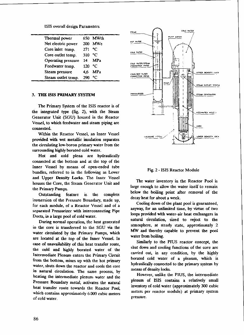
ISIS overall design ParametersCOLD w«TCK
Thermal powerNet electric powerCore inlet temp.Core outlet temp.Operating pressureFeedwater temp.Steam pressureSteam outlet temp.
650200271310141204,6290
MWthMWe°C°CMPa°CMPa°C
3. THE ISIS PRIMARY SYSTEM
The Primary System of the ISIS reactor is ofthe integrated type (fig. 2), with the SteamGenerator Unit (SGU) housed in the ReactorVessel, to which feedwater and steam piping areconnected.
Within the Reactor Vessel, an Inner Vesselprovided with wet metallic insulation separatesthe circulating low-boron primary water from thesurrounding highly borated cold water.
Hot and cold plena are hydraulicallyconnected at the bottom and at the top of theInner Vessel by means of open-ended tubebundles, referred to in the following as Lowerand Upper Density Locks. The Inner Vesselhouses the Core, the Steam Generator Unit andthe Primary Pumps.
Outstanding feature is the completeimmersion of the Pressure Boundary, made up,for each module, of a Reactor Vessel and of aseparated Pressurizer with interconnecting PipeDucts, in a large pool of cold water.
During normal operation, the heat generatedin the core is transferred to the SGU via thewater circulated by the Primary Pumps, whichare located at the top of the Inner Vessel. Incase of unavailability of this heat transfer route,the cold and highly borated water of theIntermediate Plenum enters the Primary Circuitfrom the bottom, mixes up with the hot primarywater, shuts down the reactor and cools the corein natural circulation. The same process, byheating the intermediate plenum water and thePressure Boundary metal, activates the naturalheat transfer route towards the Reactor Pool,which contains approximately 6.000 cubic metersof cold water.
UPPER DENSITY I OCK
STEAM OUTUT NOZ7.U
LOWER DENSITY I.OCK
Fig. 2 - ISIS Reactor Module
The water inventory in the Reactor Pool islarge enough to allow the water itself to remainbelow the boiling point after removal of thedecay heat for about a week.
Cooling down of the plant pool is guaranteed,anyway, for an unlimited time, by virtue of twoloops provided with water-air heat exchangers innatural circulation, sized to reject to theatmosphere, at steady state, approximately 2MW and thereby capable to prevent the poolwater from boiling.
Similarly to the PIUS reactor concept, theshut down and cooling functions of the core arecarried out, in any condition, by the highlyborated cold water of a plenum, which ishydraulically connected to the primary system bymeans of density locks.
However, unlike the PIUS, the intermediateplenum of ISIS contains a relatively smallinventory of cold water (approximately 300 cubicmeters per reactor module) at primary systempressure.
86

4. MAIN COMPONENTS Above Core Structure (ACS)
Reactor Vessel
The Reactor Vessel is of cylindrical shapewith hemispherical heads.
The construction material is low-alloy carbonsteel, internally lined with austenitic stainlesssteel.
The main openings of the Reactor Vessel arethe water/steam nozzles and the twoconnections to the Pressurizer.
Core
The reactor core consists of 69 typical (17 X17) PWR fuel assemblies with a reduced lengthto limit pressure losses.
Steam Generator Unit (SGU)
The SG features an annular tube bundle withhelicoidal tubing.
The steam is generated tube-side. The feedwater piping is connected to feed water headers,located symmetrically inside the reactor vesselwithin a calm zone, provided each with twotubeplates laid out vertically. The tubes departcircumferentially from the tubeplates.
A similar arrangement is provided at the topfor the two steam headers connections.
The vertical arrangement of the tubeplatesaims at preventing crud deposition at thetube-to-tubeplate connections, where thecorrosion is likely to occur.
The higher outer rather than inner tubepressure, a reversed situation with respect to aconventional SGU, reduces the risk of flawgrowth in the tubes.
Primary Circulation Pumps
The two Primary Pumps of the variablespeed, glandless, wet winding type (like thepumps manufactured by Hayward Tyler FluidDynamics) are fully enclosed within the ReactorVessel. The pump motor is cooled by the waterof the Intermediate Plenum.
The ACS, shaped like a flat-bottomcylindrical glass, provides the support for thecore instrumentation and forms the inner wall ofthe annular riser of the primary water. The ACSis open at the top. The water within it is part ofthe intermediate plenum and this helps to limitthe primary water inventory in the reactormodule to a minimum The ACS is flanged toand suspended from the top of the Inner Vesselfor easy removal to allow standard fuel handling.
Pressurizer
The Pressurizer is of a slim cylindrical shapewith hemispherical heads.
The pressure control function is carried outin the upper part, which is externally insulated tolimit heat losses from the steam and hot waterplena.
The remaining bottom part contains a coldwater plenum, hydraulically connected to theupper hot water plenum by means of a numberof pipes.
The function of the pipes is to enhancemixing of the hot water with the cold water, incase of water flow towards the reactor vesselduring transients.
Interconnecting Pipe Ducts
The two Pipe Ducts between Pressurizer andReactor Vessel connect hydraulically the top andthe bottom of the respective cold water plena inorder to create a common cold water plenum.
The choice of two connection levels makesnatural circulation possible in case oftemperature difference between cold plena. Ifthe normal decay heat removal route (i.e. theactive steam/water system) is lost, theuninsulated wall portion of the Pressurizer wouldthus help removing by conduction the decay heattowards the Plant Pool.
Conveyed water to and from each vessel,belonging to a common cold water plenum, doesnot significantly contribute to the thermalloadings on the pressure boundary duringtransients.
87
Air Coolers
Two tinned-tube Air Coolers are arranged inloops in natural circulation.
Each Air Cooler is rated 1 MWth at 30 °Cambient air and 95 °C pool water inlettemperature.
The onset of natural circulation occurs everytime the pool water temperature becomes higherthan the ambient air temperature.
Operation of the air coolers would prevent,for unlimited time, the pool water from boiling,in case of long-term loss of the operational decayheat removal system.
The technology of the air coolers in naturalcirculation is derived from the design andoperating experience of ANSALDO in the fieldof the LMFBRs.
5. FULL-POWER OPERATION OF THE ISISREACTOR
During normal operation the hot/cold waterinterface level in the Lower Density Lock ismaintained constant by varying the speed of thePrimary Pumps.
Any rising of the interface level iscounteracted by an increase of the pump motorspeed. Any lowering of the interface level iscounteracted by slowing down the pump speed.
Dynamic Analysis of ISIS Control System isin progress. Preliminary results, not yetpublished, confirm that the reactor power iscontrolled by the concentration of boron in theprimary water and by the intrinsic negativefeedback of the core.
6. NATURAL BEHAVIOUR OF THE ISISREACTOR UNDER ACCIDENTCONDITIONS
In the design of ISIS emphasis has been, putin the prevention of core damaging accidents.
The two main safety functions, reactorshutdown and decay heat removal, areperformed without recourse to the usual sensor-logic-actuator chain, i.e. with no inputs of"intelligence", nor external power sources ormoving mechanical parts, according to the
definition of Category B Passive Components(ref./2/).
An active Reactor Protection System, aimedat anticipating passive system interventions, isincluded in the design, but is not credited in thesafety analysis.
As anticipated in the Reactor SystemDescription, mixing of the Primary Water withthe Intermediate Water and the consequentnatural heat transfer toward the Reactor Pool isthe basic feature to assure safety under DesignBasis Accidents such as Loss Of the StationService Power and Loss of Heat Sink (ref. /3/).
During these DB Accidents the pressureboundary integrity assures the availability ofwater to cool the core and to transfer the decayheat to the Reactor Pool.
In case of LOCA Accidents, the Coreshutdown and cooling functions are possible onlyif a sufficient inventory of water remainsavailable.
The design features of ISIS guarantee theavailability of this water because of the promptself-depressurization of the system which is theconsequence of the same hot-cold water mixingprocess.
To illustrate the effectiveness of this self-depressurization capability, the two followingDB Accidents are presented :- double ended break of the lower pipe
connection between RPV and Pressurizer;- Steam Generator tube rupture.
Additionally, the extremely fast transientfollowing an hypothetical break at the bottom ofthe RPV is reported as an exercise to betterunderstand the thennalhydraulic phenomenalinked to the self-depressurization.
All transient analyses have been carried outusing the RELAP5 computer code, with anodalization made up of 256 control volumes 262flow junctions and 78 heat structures; neutronicpoint kinetics has been used to evaluate thepower in the core.
Loss Of Coolant Accident
This accident consists in a double ended break ofthe lower, 150 mm nominal diameter lineconnecting the RPV and the Pressurizer. Thisaccident scenario has been chosen because this is
88

the largest line of the pressure boundary andalso because the break location is far from bothDensity Locks, thus worsening the loss of coldwater from the vessels (ref. /4/).
Considering that, the break location is 25 mbelow the Reactor Pool water level, the absolutepressure at the break outside the RPV is 3.5 bar.No action is credited of any active protection orcontrol system.
When the accident starts, interconnectedthermalhydraulic phenomena occursimultaneously within both RPV and Pressurizer.Cold water outflows from both RPV andPressurizer; hot primary water replaces thelosses in the Intermediate Plenum through bothDensity Locks. This phase lasts about 2-3seconds. Then flashing hot water causes PrimaryPumps cavitation which, in turn, allows the inletof intermediate water into the primary systemand the Core via the Lower Density Lock with aquick decrease of generated power.
The Reactor behaviour can now be explainedconsidering that the Primary Pumps remaincavitating all over the transient and the primarysystem behaves like two channels hydraulicallyconnected in parallel.
Both channels, the one made up by the Coreand the Riser, and the second by theDowncomer and the SGU, are alternativelyflooded by intermediate water entering theprimary system through the Lower Density Lock.Self-depressurization of the system takes placemainly because of the following two watermixing effects (fig. 3):
In the RPV. hot primary water flowing fromthe Upper Density Lock mixes up with the largevolume of cold intermediate water of the RPVHead, purposely provided for this function l .
In the Pressurizer. hot water flowing downthrough the vertical pipes mixes up with thelarge volume of cold intermediate waterunderneath.
The system pressure at the break equals theexternal pressure in about 450 seconds.
1 Thermalhydraulic phenomena in the largeplenum of the RPV Head would be betterpredicted by a 3D code which is, in any case,needed to optimize the design of the internalstructures to enhance water mixing in thisregion.
— i —— i —— i0 10O 200 3OO
i —— i —— i —— i —— i —5OO 6OO 7OO BOO 9OO 1OOO
TIME (S)
Fig.3-LOCACore pressure
At this moment the RPV water stops flowing outand reversal flow of cold, high-boron water fromthe Reactor Pool sets on.The core is shutdown (fig. 4) by intermediatewater entering through the Lower Density Lock.
7OO
100I I I I T i l l
200 JOO «00 bOO 6OO . /OO 800 9OO 10OO
Fig. 4 - LOCANuclear power
Figure 5 shows that the maximum cumulatedamount of water loss is less than 120t(approximately 25% of the initial inventory) andonly the following regions of the Reactor
Module remain temporary uncovered:- the Head of the RPV (with the water level
always remaining above the Upper DensityLock);
- the Pumps, the upper part of the Riser andthe SGU;
- the hot region of the Pressurizer.
89

Later on in the transient, reversal flow fromthe Reactor Pool starts recovering the waterlevel in the RPV; at the end of the computer run(i.e. after 900 seconds) about 40 t of water havealready entered the RPV from the Reactor Pool.
120
i——i——i——\——i——i——i——i——rO TOO 2OO -JOO 40O bOO 6OO 70O (JOO 9OO >OOO
1IM£ (S)
Kg.5-LOCACumulated water loss
During the transient the Core never uncoversor heats up as shown in Figure 6. The maximumtemperature of the "average" fuel rod hasremained lower than at nominal conditions. Asimilar behaviour is shown for the clad surfacetemperature.
100 1OQ iOO 400 iOO 600 700 800 900 IOOO
IIMLFig. 6 - LOCA
Maximum temperature of average fuel rod
Steam Generator Tube Rupture
In this accident a break of 10 cm^ crosssection located at the connection between SGU
tubes and steam headers is simulated; the breaksize is approximately equivalent to the cumulatedcross sections of 8 SGU tubes.
No credit has been taken for action of activesystems that can mitigate the consequence of theaccident, but for the Primary Pumps SpeedControl System which delays the inlet of highlyberated water through the Lower Density Lock.The steam pressure and the feedwater flow rateare assumed accordingly to remain constantduring the transient.2
When the accident occurs, water from theprimary system enters the SGU ruptured tubesat a max mass flow rate of 96.5 Kg/s.
An equal amount of intermediate waterenters the primary system through the UpperDensity Lock as long as the Primary PumpControl System is capable to control the hot-coldinterface level in the Lower Density Lock.
Primary water with increasing boronconcentration enters the core and reduces thegenerated power (fig. 7).
/oo -
I \8O " t O O 120 1 40
TlMt (S)
Fig. 7 - Steam Generator Tube RuptureNuclear power
The amount of intermediate water enteringthe Upper Density Lock is replaced in the RPVby water leaving the Pressurizer. In thePressurizer itself fast depressurization takesplace because of the hot-cold water mixingprocess already explained above for the LOCA
2 Crediting the SGU isolation, the transientwould behave very similar to the transient of lossof heat sink which has been shown to cause a fastreactor shutdown (ref. /4/)
90

transient.Both effects of reduced core power with
associated lower primary water temperature andPressurizer self-depressurization reduce theoverall primary system pressure (fig. 8) down tothe secondary system pressure (tube-side SOUpressure) which has been assumed to remain atits nominal value.
BO 100 120 MO
11MI. (b)
Fig. 8 - Steam Generator Tube RuptureCore pressure
At this time the primary water stops flowinginto the SOU tubes. Figure 9 shows that thecumulated amount of water loss is less than 8tonnes which corresponds to the inventory of thehot water in the pressurizer.
The curve of the fuel temperature shows asteadely decreasing pattern, fig. 10.
1 1OO
10OO
900
700
60O
MX)
400
Fig. 9 - Steam Generator Tube RuptureCumulated water loss
fig. 10 - Steam Generator Tube RuptureMaximum temperature of average fuel rod
Break at the bottom of the Pressure Vessel
In this exercise an hypothetical break of 500cm2 cross section has been assumed to occur atthe bottom of reactor pressure vessel; thisaccident scenario is arbitrary and imagined togenerate a very severe thermalhydraulictransient; in fact the break is positioned at thelowest location of pressure boundary andtherefore has the potential of completelyemptying the RPV. This exercise is intended todemonstrate that the self-depressurizationprocess can avoid the uncovering of the coreeven in this case. No protection or controlsystems, no any other active system was creditedduring the accident analysis.
When the transient starts, there is a largeblowdown of intermediate water from the RPVand Pressurizer into the Reactor Pool (the initialmass flow rate through the break is about 7000kg/s). The escaping flow rate is fed by displacedprimary water which is mostly contained in theSGU. Primary water leaves the SGU from thebottom via the Downcomer and, after fewseconds, also from the top via the PrimaryPumps and Upper Density Lock.
At the very begining of the transient thewater flowing down through the Downcamersplits in two streams: the one leaves the InnerVessel through the Lower Density Lock and thesecond flows up through the Core, the Riser andleaves the Inner Vessel through the UpperDensity Lock. The reactor core is continously fed
~1——————I——————I——————I——————I————«() (:() HO Hl(; 1,>O 14(1
llMI
91

by primary water flowing upwards and itstemperature is continuously decreasing becauseit is kept cooled since the beginning of thetransient.
At the time of about 7 seconds, with PrimaryPumps in cavitation, the primary water stopsleaving the Inner Vessel through the LowerDensity Lock and a reversal flow of intermediatewater sets on flooding the core.
At this moment the usual way of naturalcirculation of ISIS reactor is recovered and theprimary system fed with cold and borated water.
The mixing of cold and hot water initiates theself-depressurization of the system in the waydescribed before for the case of LOCA (fig. 11).
The system continues its depressurization upto the time of about 200 seconds when itspressure drops below the Reactor Pool pressureat the break location.
The evolution of the generated power isshown in fig. 13; the power reduction during thefirst 7 seconds is caused by the void effectassociated to the depressurization and thefollowing shutdown is assured by the boratedwater.
2Oxicr
15x1O*
IDxIO*
,C 5x10*
Ox 10*
-Sxltf,
' /f-"\\
X\^
:
:
:
3 200 400 600 800 KJOO 12OC
IiwE (S)
10
200 4OO 600 8OO 10OO 1200
TIME (S)
Fig. 11 - Break at the bottom of the RPVCore pressure
Fig. 12 - Break at the bottom of the RPVCumulated water loss
800
600
40O
200
0.02OO 4OO 600 800 10OO 12OO
TIME (S)
At this moment, the total mass of displacedwater (figure 12) is less than 200 tonnes(approximately 50% of the total inventory of onemodule) and the RPV has been emptied onlydown to about the center line of the SOU.
After about 1000 seconds, the initial waterinventory is completely recovered and thereactor is in the state of stable cold shutdown.
Fig. 13 - Break at the bottom of the RPVNuclear power
The fuel temperature has steadily decreasedas shown in fig. 14 and 15.
92

l̂ UU
100O
O fiW~t
uQ;
CT
a 400Z
200
0
i.I
\
^-V.- e ̂. . .
D 2<
* - * " - -
X) 4(
.-. .....jjJ .̂
X) 6<» a
. ..._... . ....
X) 10
' ' ' i—— ii
]....... ;. .
00 120CIIME (S)
Fig. 14 - Break at the bottom of the RP VMaximum temperature of average fuel rod
35O
300
250
u, 200
200 400 600 800 1000 12OO
150
IOO
Fig. 15 - Break at the bottom of the RPVClad surface temperature at different elevations
7. Modular And Compact Plant
The present international trend in the nuclearindustry focuses on the simplification of thenuclear plants and on the reduction of theconstruction time. The reduced size of the mostattractive modular reactors is dictated by thedesign target to remove the decay heat directlythrough the wall of the reactor vessel itself,thereby drastically reducing the number ofsafety-related systems.
The selected unit power of the ISIS ReactorModule (200 MWe) is consistent with this designtarget.
Layout studies of the ISIS power plant are inprogress in ANSALDO, to optimize componentarrangement and reduce erection time of theReactor Modules and of the Balance of thePlant.
The compact reactor layout is made possibleby the integrated design of the primary circuit.
8. Economic aspects
At the beginning of the development of theISIS concept (about seven years ago) it seemedreasonable to foreseen a moderate increase ofthe cost of the fossil fuels in the near futurewhich would have improved the economiccompetitiveness of nuclear energy. Today,instead, two facts worsen this competitiveness:- the fossil fuels price has remained low andstable,- the efficiency of the modern electric energy
generating conventional power plants iscontinuously increasing.The importance of the second fact is such
that it wfll drastically affect the energy market,in particular it will impact the market of nuclearenergy.
In the past, the efficiency of electricityproduction of the nuclear power plants wassimilar to that of the conventional power plants.Under that condition it was profitable togenerate electricity by the large-size nuclearpower plants that dominate the nuclearpanorama.
Today, the efficiency of the modernCombined Cycle Turbo-Gas (CCTG) PowerPlants has exceeded 50% and in the near future(before the year 2000) will reach and perhapstrespass 60%, while the one of the nuclear waterreactors stagnates at about 33%.This new fact will have two main consequences:- if the cost of fossil fuels remains stable, the
cost of heat will remain substantially stable,but the cost of electricity will be reduced;
- the ratio electricity/heat production willincrease up to the optimum dictated by themodern fossil-fired co-generative powerplants.Qualitatively it can be affirmed that today an
efficient use of energy favours the fossil fuels forelectricity and of the nuclear fuel for heatproduction, because of the lower electricefficiency of the nuclear power plants.
Quantitatively, a preliminary economicevaluation carried out comparing 60% efficientCCTG, co-generative CCTG, conventionalboilers and nuclear power plants, has shown thatnuclear power plants could recover part of theirlost economic attractiveness only if exploited as
93

co-generating or as thermal power plants.The co-generative use appears attractive
from 3000 hours/yr. and the thermal use from5000 hours/yr. upwards (increase of the value ofthe plant in the order of more then 50 %)
The increase of the value of the plant ismore important for co- generative reactors andcan largely exceed 100% for specific siteconditions where heat can be used during themost part of the year.
A trivial condition for any interest of aprospective utility in a co-generative nuclearplant is that an adequate co-generating reactorexists. For this the reactor designers, besidesproviding the reactor with convincingcharacteristics of radiological safety, have toovercome the unfavourable scale-effect ofdownsizing, because the thermal power neededis mostly in the order of hundreds of megawattsagainst the thousands of megawatts availablefrom the today large nuclear reactor conceivedfor electricity generation only.
In the view of a reactor designer, the smallerreactor can be competitive, in spite ofdownsizing, provided that:- the number of systems of the larger plants is
strongly reduced,- the specific mass of steel of the NSS it is not
significantly increased (scale effectneutralised),
- the specific operation & maintenance costsbecome not excessive.The co-generating version of the ISIS reactor
is being designed to cope with theserequirements.
The technical features illustrated in thisarticle and the results of preliminary analyses foran use of ISIS as co-generating reactor can besummarised as follows:- no active safety system is necessary to assure
safety. All active safety systems can beeliminated.
- no adverse scale effect on the specific mass ofsteel of the ISIS NSSS with respect to thelarger modern PWRs. This is possible alsothanks to the milder operating conditions of areactor designed for co-generation (e.g.,lower operating pressure ).Ongoing studies explore furthermore the
possibility of reducing operating & maintenance
costs, taking profit of the predicted simpleoperation of ISIS, of the reduced number ofsystems, of the modular approach that makespossible to share facilities, such as fuel har»dl'"gand component handling equipment, betweenthe reactor modules installed in the same reactorbuilding.
9. CONCLUSION
The ISIS is an innovative Nuclear PowerPlant under development in ANSALDO. It isbased on original ideas derived by ANSALDOexperience on proven LWR and LMRtechnologies.The main features of ISIS are as follows:
Outstanding passive safe behaviour of theReactor, which means core shut down andcooling functions ensured in all accidentconditions and no release of primary coolantoutside the Reactor Building.
- Compact reactor layout, associated withmodular fabrication and erection, madepossible by the integrated design of theprimary circuit.
- Reactor concept flexible for combinedgeneration of heat and electricity madepossible by the modular solution and the lowsensitivity to downsizing.
References
/!/ PIUS, the forgiving reactor by ASEA-ATOM,Modern Power System (October 1985)
/2/ INTERNATIONAL ATOMIC ENERGYAGENCY, 1991 - Safety related terms foradvanced nuclear plants - IAEATECDOC - 626, Vienna.
/3/ AMATO S., MONASTEROLO U.,MONTI R^ ORAZt A^ 1991 - Response ofthe Inherently Safe Immersed System (ISIS)Reactor to Accident Conditions - Third Int.Sem. on SMNRs, New Delhi.
/4/ AMATO S., ORAZI A., 1993 - AdvancedSafety Features in Conception of NewPassive Reactors: the Inherently SafeImmersed System (ISIS) Reactor - IAEA
94

Technical Committee Meeting onThennohydraulic of Cooling Systems inAdvanced Water Cooled Reactor, VUligen,Switzerland.
/5/ CINOTTI U, RIZZO RL, 1993 - TheInherently Safe Immersed System (ISIS)reactor - NucL Eng. Des. VoL 143; pp. 295-300.
/6/ AMATO S., ONOTTI L~, 1994 - Usingprompt self-depressurization as a key featureto assure safety - Int. Conf. on New Trendsin Nuclear System Termohydraulics, Pisa,Italy
95

AN INTEGRATED NUCLEAR REACTOR UNIT FOR XA9745977A FLOATING LOW CAPACITY NUCLEAR POWERPLANT DESIGNED FOR POWER SUPPLY INREMOTE AREAS WITH DIFFICULT ACCESS
A.N. ACHKASOV, G.I. GRECHKO, O.G. GLADKOV,V.L. PAVLOV, V.N. PEPA, V.A. SHISHKINResearch and Development Institute of Power Engineering,Moscow, Russian Federation
Abstract
The paper describes the conceptual design of an integrated advanced safetynuclear reactor unit for a low capacity floating NPP designed for power supply in areaswhich are remote with difficult access.
The paper describes the major structural and lay-out components of the steamgenerator and reactor units with main technical characteristics.
Conceptual design of a reactor facility with enhanced safety for a low capacityfloating and environment friendly NPP has been developed in Research andDevelopment Institute of Power Engineering to provide electricity supply to areaswhich are remote with difficult access.
The most advanced technical solutions well mastered during recent years indesigning of navy nuclear power facilities have been used.
The following technical solutions provide high safety level of the reactor facility:• application of well mastered technology of water-cooled reactors with
developed inherent safety features;• location of the total primary circuit equipment into one vessel of an integrated
nuclear steam supply system (NSSS);r • provision of defence - in-depth barriers to prevent ionizing radiation and
radioactive fission products release into environment, realization of technicalmeasures to protect confining barriers and maintain their effectiveness;
• application of safety systems, mainly based on passive operation principle;• independence from external power sources.The Development of the reactor facility (RF) for floating NPP was carried out in
compliance with current Russian rules and requirements to provide safety of stationaryand floating nuclear power plants and ship nuclear power facilities and in accordancewith the modern notion of prospect enhanced safety NPPs, elaborated so far by theworld community. It was considered that RF met safety requirements, if its radiationeffect on personnel, population and environment in normal operation and design-basisaccidents did not lead to excess of specified dose rates, and limits this effect in beyonddesign-basis accidents. Technical and organizational measures were assumed to ensuresafety with any design-basis initial event with superposition of one failure independentof the initial event of any of the following safety system components: active or passivecomponent having mechanical -movable parts or one personnel error independent of theinitial event. Besides one failure independent of the initial event, a nondetectable failureof components, not monitored during operation, which influences accidentpropagation, and results in violation of safe operation limits is taken into account.
97

• Fig.l. Reactor facility flow diagram:1 - core; 2 - steam generator; 3 - pressurizer; 4 -
primary circuit, electric circulation pump; 5 -steam-generating system vessel; 6 - iron-water shieldingtank; 7 - bubbling tank; 8 - high pressure gas cylinder; 9 -emergency flooding cylinder; 10 - emergency cooldown tank;11 - heat-echanger-condenser; 12 - safeguard housing; 13 -containment.
98

•r~1_
.^r**'
"1-J i
•
•
Fie.2. Reactor facility general arrangement. Elevation:1 - bubbling tank; 2 - iron-water shielding tank; 3 -
steam-generating system; 4 - containment; 5 - safeguardhousing; 6 - emergency cooldown heat-echange - condenser;7 - high pressure gas cylinder; 8 - refuelling and repairroom.
99

Fig.3. Reactor facility general arrangement. Plan:1 - steam-generating system No.1; 2 - steam-generating
system No.2; 3 - isolating valves for steam and secondarycircuit feedwater; 4 - emergency cooldown tank; 5emergency flooding cylinder; 6 - strong leaktight partition.
Structurally the RF is divided into two separate and independently operatingsteam generating facilities with identical principal flow charts and equipment (see Figs.1-3).
The RF employs water-moderated, water-cooled reactors with inherent safetyand control features due to negative power and temperature reactivity coefficients. Thecore physical characteristics are so selected that the above coefficients be negative in theentire range of temperatures during core life. This eliminates spontaneous reactor powerexcursion in normal startup and heatup and stabilizes operation in steady-stateconditions and transients.
The adopted core structure rules out the possibility of forming local criticalmasses both in normal and emergency modes. Formation of secondary critical mass inhypothetical accidents, resulting in partial or full core melting is also excluded.
All equipment of the primary circuit (the core with reactivity compensationcomponents, steam generator, electric circulation pumps, pressurizer) except gascylinders are located in cylindric vessel of the integrated nuclear steam supply system(NSSS) (see Fig. 4).
100

8
Steam-generating system:1 - vessel; 2 - ring- type cover; 3 - core; 4 - steam
generator; 5 - pressurizer; 6 - intermediate capacity; 7 -electric circulation pump; 8 - control and protectionmembers drives.
101

The pipeline between gas cylinders with pressurizer and make p system pipelinesis connected to the NSSS cover and ends at this point.
Such NSSS structure allows:• to reduce the number and extent of external primary circuit lines down to
minimum and reduce probability of its depressurization;• to provide high level of natural circulation for the primary circuit coolant;• to increase water volume above the core and to improve its cooling conditions
in a hypothetical accident related to primary circuit depressurization and watercut-off from the NSSS.In order to decrease the leak and mitigate accident consequences in case of
pipeline rupture which connects pressurizer with receiving cylinders, a constrictingdevice is installed on it. Check valves are installed on makeup pipelines (in places of itsattachement to NSSS cover).
RF employs defence-in-depth principle, based on barrier system to preventionizing radiation and radioactive substances release into environment supported bytechnical procedures to protect these barriers and maintain their efficiency.
In accordance with this the RF safety systems provide for:• reactor emergency trip and keeping it subcritical;• emergency heat removal from the core;• confining of radioactive products within specified boundaries.Flow chart and design of these systems are based on their passive action as much
as possible. In order to ensure reactor emergency trip and keeping it subcritical thefollowing systems have been designed:
• main emergency protection;• additional emergency protection;• liquid absorber injection system.The main and additional emergency protections have different activation
principles. They are activated automatically by CPS and complex system for technicalmeans control (CSTMC) signals or by power cut-off.
Liquid absorber is injected by remote control.Design of all compensating group (CG) activation devices is based on insertion of
shim rods into the core using dump springs or the rods weight during power cut-offfrom actuators and CPS; the design also ensures keeping shim rods in inserted positionin case of the unit turning-over.
The shim rods ensure reactor tripping and keeping it subcritical in alloperational modes in case of one (any) CG failure (stuck in the extreme position) bymeans of CGs remaining in operation.
Additional emergency protection is activated automatically by a signal fromCPS in response to failure of two or more CGs.
Besides activation by CPS signals the additional emergency protection becomesoperational without any external signal under increase of primary circuit coolanttemperature up to specified ultimate value. This is achieved by the additional emergencyprotection design.
102
Liquid absorber is injected into integrated NSSS only when the reactor has notbeen transferred to subcritical state due to failures of the main and additionalemergency protections, but such situation is hardly probable.
Availability of the listed means for reactor emergency protection and keeping itsubcritical can provide safety reactor trip not only in case of design-basis accidents, butalso in hypothetical accidents, which are not related to core or NSSS damage.
In order to avoid spontaneous chain reaction during scheduled maintainance orrepair works, CG actuator design envisages clutches, which are installed below "cold"startup position. Electromagnetic clutches are opened only by signals, which allow thecore start-up.
To provide heat removal from the core in different emergency situations the RFhas the following safety systems:
• emergency cooling system;• emergency core flooding and cooling system.RF can be cooled down by feedwater pumping into the steam generator by the
steam-turbine means in both operational and emergency modes. In case of primarycircuit depressurization the makeup system is also involved in heat removal from thecore.
In emergency situations, which are not related to steam turbine failure, the RF isusually cooled by feedwater pumped into the steam generator by steam turbine. In caseof the steam turbine failure and during power cut-off the integrated NSSS isautomatically disconnected from the steam turbine (from steam and feedwater supply)and emergency cooling system (ECS) starts operating. Heat removal from primarycoolant is provided for both operating and non-operating primary circuit electriccirculation pumps (due to natural coolant circulation). In case of RF power supply lossthe disconnection of NSSS from steam turbine and ECS activation are ensured byisolating and cut-off valves, which perform this function in "normal" position.
Emergency cooling system, consisting of 4 independent sections, can provideNSSS cooling during 24 hours in case of failure of any 2 ECS sections even with theplant blackout. Heat removal from primary coolant and its transfer to water in ECStanks results from coolant natural circulation in this system. With electric supplyavailiable the water in ECS is cooled by pumping it through heat exchangers, which arecooled by outboard water. In case of NPP power blackout heat from ECS heatexchangers is removed due to heating followed by evaporation of water from ECStanks.
Core makeup and core emergency flooding systems provide removal of residualheat from the core and eliminate its drying and further melting in case of primarycircuit depressurization and coolant circulation failure. Each of these systems hasredundances with respect to equipment and water supply channels to NSSS. Themakeup system operates automatically by pressure drop in primary circuit signal fromCSTMS and activation of the emergency core flooding system does not require anyoperator actions or CSTMC activation and occures due to membrane rupture underprimary circuit pressure decrease down to specified level.
Taking into account that the makeup system besides RF normal operationassurance is supposed to provide safety, three independent NSSS water supply channelswith high pressure pumps in each channel are envisaged in the makeup system. Waterfor primary circuit makeup is taken from condensate-feedwater system of steam turbineor from water storage tanks, and after water level in bubbling tank reaches specifiedlevel the makeup is performed in closed cycle, i.e. water for makeup is taken from
103

bubbling tank, cooled in heat exchangers and delivered into NSSS; the coolant, flowingfrom NSSS again comes into the bubbling tank.
The emergency core flooding system is based on passive operation principle andcomprises two independent channels. Water is supplied into NSSS through thesechannels due to gas pressure from pressure cylinders.
In case of primary circuit depressurization the feedwater is delivered into steamgenerator from steam turbine in parallel with operation of makeup and emergency corefloodibg systems. This ensures additional removal of heat, released in the core andincreases time needed for the core drying in hypothetical accidents due to naturalconvection of gas and steam in NSSS and partial steam condensation on steamgenerator surface. Steam turbine failure to supply water into the steam generatoractivates the ECS.
The availability of cooled iron-water shield around NSSS vessel and favourableconditions for natural circulation of steam-gas medium inside NSSS thereby reduceprobability of core melting in hypothetical accidents and eliminate possibility of NSSSvessel melting down in such accidents.
In case of an accident, all actions to localize it are automatic. Control systems(CPS and CSTMC) have three-channel scheme and the control and emergency signalsare generated using major principle (2 out of 3) that ensures sufficient operationalreliability.
The following safety barriers are envisaged to reduce radioactivity release intoenvironment in design - basis and hypothetical accidents:
• corrosion resistant matrix of fuel elements;• claddings of fuel elements;• leaktight primary circuit;• safeguard vessel;• containment.Small number of the equipment, its lifetime characteristics and high automation
degree ensure RF operation during one year without maintenance within thecontainment. This allows to adopt additional technical measures to enhance RF safety.Namely, ventilation system equipment located outside the containment is isolated withisolation valves designed for maximum emergency pressure in safeguard vessel, and ismade operational only when it is necessary to make repairs inside the containment (gasis discharged from containment into environment via special filters under control).Conditioning system operates in closed cycle, its total equipment is located in safeguardvessel. Such technical solutions eliminate radionuclides release from containment innormal operation of floating NPP.
Leaktightness of the containment and safeguard vessel and no inside repairsallow to maintain decreased oxygen content (11-13 %) in equipment rooms, thusenhancing their fire safety.
The RF design solutions eliminate a possibility of safeguard vessel and primarycircuit damage in case of earthquakes, aircraft crash or other external impacts.
104
In conclusion, the basic technical characteristics of the reactor facility are asfollows:Thermal power, MWtSteam output, t/hSuperheated steam parameters:
temperature, °Cpressure, MPa
Core life as evaluated for nominal power, hSpecific core power rating, kW/1Fuel composition
Enrichment with U235, %Time period of RF continuous operationwithout maintenance, hMass, including safeguard vesselcontainment, t
and
2*422*60
2903.532000068.0uranium dioxidedispersed inzirconium matrix218000
750
Due to high safety level (probability of severe beyond design-basis accidents,which can result in serious core damage or melting and following radionuclides releaseinto environment does not exceed 2xlOa5-8 aOper reactor per year) the RF can berecommended to be used for low capacity floating NPP, and its unique mass-dimensioncharacteristics enable to construct a plant with such a draught (estimated as 2.6 m),which will make it possible to ship it along Nothern rivers to regions which are far awayfrom the coast.
105

AN AUTONOMOUS NUCLEAR POWER PLANT WITH XA9745978INTEGRATED NUCLEAR STEAM SUPPLY SYSTEMDESIGNED FOR ELECTRIC POWER AND HEATSUPPLY IN REMOTE AREAS WITH DIFFICULT ACCESS
L.A. ADAMOVICH, G.I. GRECHKO, B.D. LAPIN,V.K. ULASEVICH, V.A. SHISHKINResearch and Development Institute of Power Engineering,Moscow, Russian Federation
Abstract
The paper contains basic conceptual principles used to develop the technical assignment foran autonomous nuclear power plant with integrated nuclear steam supply system (NSSS)designed to provide heat and electricity for areas which are remote with difficult access. Thepaper also describes technical procedures and equipment, NPP thermal hydraulic flow chart,steam generator design, safety aspects as well as operational and maintenance procedures.
1. Introduction
In areas of Russia which are remote with difficult access, for instance in the Extreme North,Far East, or Siberia a possible reasonable alternative to fossil-fuel energy sources, mainlyhydrocarbon, is autonomous nuclear power plants (NPP) of relatively low capacity, shipped to thesite in large modules and completely withdrawable from the site upon decommissioning. For theareas in question, small setllements and enterprises with low power demand are typical. Thecomplexity of constructing electric transmission lines, gas pipelines, liquid fuel pipelines, and highcost requires to use local self-contained energy sources. Application of NPPs for power and heatsupply may be cost efficient and promising from social and ecological point of view.
A necessity arises to develop new approaches to designing these power sources, naturally,taking into account the experience gained in reactor construction based on modern safety level.Such approaches are to be based on:
• use of well proven technology of water-cooled reactors, in particular, those used attransport facilities with adequate optimisation of their characteristics;
• maximum use of equipment which has operational field-checked prototypes;
• use of designs with inherent safety features;
• maximum ecological safety of NPP considering nature specifics in the Extreme Northand Far East of Russia extraordinarily sensitive to production activities
• preservation of the natural landscape, flora and fauna due to NPP delivery and removalin large plant-manufactured modules which minimize erection and dismantling jobs atthe site;
• minimal capital investments and operating costs to make such NPP competitive withconventional fossil power plants.
The paper briefly describes possible implementation of these approaches using a NPPequipped with the integrated nuclear steam supply system.
107

o00
15
Fig.l. UNITHERM NPP DiagramI - Reactor unit; 2 - turbine unit; 3 - heat supply unit; 4 - safeguard housing; 5 - contaiment; 6 - shock-proof casing; 7 - steam generating
unit; 8 - core; 9 - intermediate circuit heat exchanger; 10 - steam generator; 11 - emergency cooling system heat exchanger; 12 - turbine;13 - generator; 14 - air cooled condenser; 15 - transformer unit

2. Selection of thermal and technical parameters of a nuclear powerplant (NPP). Integrated nuclear steam generating unit design and its maincomponents
The UNITHERM NPP thermal-hydraulic cycle (Fig.I) includes three interrelated processloops, the last of which accommodates all heat consumers (turbine-generator unit and heat systemor process steam boilers).
Selection of coolant parameters for the above-mentioned process loops was based on theproven range of operating pressures and temperatures typical for NPP water-cooled reactorprimary circuits, and on the experience with mobile NPP operating with primary coolant naturalcirculation Besides, variation limits of the primary coolant parameters without reactivitycompensation of nuclear fuel burnup by control rods were taken into account On the other hand,selection of coolant operating temperatures and pressures for the intermediate and steam-turbine•loops was greatly influenced by the conditions which could provide acceptable efficiency andorientation on the development and operating expenence with steam turbine units that might beconsidered as existing prototypes. The analysis of thermal characteristics of steam turbine units ofsuch type enabled selection, taking into account the above reasons, of coolant parameters for theprocess loop of heat consumers
Transport of heat from the primary circuit to heat consumers during the phase change in theintermediate loops reduces the required coolant flows and increases pressure in the naturalcirculation system, while the desire of optimal distribution of the available temperature differencebetween the coolants of the primary and third circuits determines the intermediate loop coolantparameters Considering the above reasons, the parameters of the UNITHERM NPP process loopcoolants are as in Table 1 below.
Table 1
The UNTTHERM NPP process loop coolant parameters
Parameter
Primary coolant parameters (high-purity water of NPPprimary coolant quality)
pressure, MPa
core inlet temperature, °C
core outlet temperature, °C,
Intermediate loop coolant parameters (water of NPPsecondary coolant quality).
pressure, MPa
temperature, °C
Heat consumer loop coolant parameters (water of NPPsecondary coolant quality)
pressure, MPa
steam temperature, °C
feedwater temperature, °C
Value
16.0 16 5
245 225
325 305
30
234
1.0 . 12
207 210
45 60
109

Fig.2. Nuclear Steam Supply System1 - Vessel; 2 - core; 3 - intermediate circuit heat exchanger;4 - presiurizer; 5 - steam generator; 6 - control rods drive
The proposed UNITHERM NPP has been designed to employ integrated water-cooledNSSS as a heat source (Fig. 2). NSSS combines in one vessel the main primary circuitcomponents - core, steam generator (SG), pressurizer, control and protection elements. Thisallows to avoid primary circuit pipework, reach extremely compact location of ionizing radiationsources and potentially dangerous working fluid - primary coolant. The NSSS design ensures corecooling and heat supply to steam generator by convection of primary coolant and thereby allowsto eliminate forced circulation. Such approach to the design of the NPP main component -nuclear reactor - is necessary to reach maximum possible reliability and simplicity due to absenceof active elements with continuously moving mechanical parts. The group of absorbers with
110
associated drives, which perform the function of emergency protection and compensation forreactivity variation, is a single movable element. The absorbers are displaced once during NPPcontinuous operation when starting NSSS unit in normal operation. In emergency situations it ispossible to drop the absorbers which perform the function of emergency protection.
The integrated NSSS vessel made of 15X2MFA-A steel with corrosion-resistant claddingconsists of the shell with welded elliptical bottom and flange.
The central part of the vessel accommodates the removable shield with the core, lattices ofabsorber rods and devices of additional emergency protection. The thermal shield which alsofunctions as core reflector and radiation and thermal shield, is arranged around the removableshield in the bottom section of the vessel.
Inside the removable shield above the core there is a cavity with pressurizer equipped with aset of flat screens serving as upper radiation shield.
In the annular space between vessel and removable shield the steam generator tube systembanks are located. Intermediate circuit heat exchanger is heat exchanger with coil-type heattransfer surface, where primary coolant moves in the tubes while the intermediate circuit fluidmoves in the intertube space. The heat transfer surface is made up by 24 banks of the same type,the shells of which are designed to withstand the primary circuit pressure. The banks are pairwisecombined into 12 assemblies which are connected to 12 sections of the intermediate circuit heatexchanger.
Steam collecting headers and water distribution chambers of intermediate circuit heatexchanger sections are located in the vessel flange area. The chambers are also connection pointsof SG sections to the NSSS vessel. The shell of each SG section is a cylindrical vessel withwelded spherical bottom with a coil-type tube system inside cooled by the coolant from the heatconsumer circuit. In each section of the SG above the tube system the coil-type system ofindependent cooldown circuit is arranged. From the top the shell is closed with a spherical head.
In the choice of characteristics and structure of the core and its control elements thefollowing priority concepts have been adopted:
• maximum possible reduction of operative reactivity margin, in particular, the fraction oftotal efficiency of shim elements, per group of absorber rods with individual drive;
• optimaTpower, coolant temperature and fuel feedback factors;
• specific power density (about 15 kW/1) which guarantees specified long-term operationwithout fuel element clad leaking, and minimum specific levels of residual heat releasefor reliable heat removal in severe accidents;
• increased reliability of emergency core chain reaction suppression system by using inthe control system of additional passive emergency protection channels with operationmechanism differing from that of main functional components.
To reduce core overall reactivity the adopted design philosophy excludes withdrawal ofcontrol elements from the core in power generation mode during continuous NPP operation. Inthis period, the core operates in self-control mode due to variation of coolant average temperatureand absorber burnup.
I l l

The additional emergency protection actuator is a structure with leaktight vessel, which byits lower part enters the core instead of one fuel assembly, while the upper part is flangeconnected to the NSSS vessel head. Inside the actuator vessel, actuating element consisting of theaccumulator with absorber and interconnected receiving chamber made of two elastic membranes.The space between the vessel and the actuating element is filled with nitrogen, control fluid. Gas(He-3 or boron trifluoride) is used as absorber.
When there is no emergency signal, the membranes of the receiving chamber are undercontrol fluid pressure and the absorber is displaced into the accumulator. The emergency signalactivates the electromagnetic switch and control fluid is discharged to the NPP containmentvolume. By its pressure in the accumulator the absorber is displaced to the receiving chamberspacing the membranes apart. To return additional emergency protection to initial position, thecontrol fluid from the tank outside NSSS vessel is fed to the actuator which compresses themembranes and displaces the absorber to the accumulator.
3. Design Safety AspectsIn accordance with modern NPP safety approaches, radiation exposure on personnel,
population and environment in normal operation and design-basis accidents should not lead toexcess dose rates for people, and in beyond design-basis accidents, this effect should reasonablylimited. To this end, technical and organisational measures are taken to ensure safety with anyinitiating event envisaged by the design with superposition of one failure independent of theinitiating event of any of the following safety system element: active or passive element withmechanical movable parts or one personnel error independent of the initiating event. Besides onefailure independent of the initiating event, it is necessary to take into account the nondetectablefailure of elements affecting safe operation, which are uncontrolled in operation, and influencingaccident propagation.
Safety of the UNITHERM NPP is achieved by a complex of technical solutions amongwhich the following are worth mentioning.
The NPP employs water-moderated, water-cooled reactor with inherent safety featureswhich reflect its capability of keeping safety on the basis of internal feedbacks, natural physicalprocesses applying passive residual heat removal systems and automatic protection devices whichensure chain fission reaction suppresion without intervention of operator. The UNITHERM NPPis also capable of self-controlling chain fission reaction due to negative temperature, power andvoid coefficients of reactivity. The core physical characteristics are so selected that the abovecoefficients are negative in the entire range of temperatures during the core life both in normaland emergency operation modes. This eliminates spontaneous core power excursion in normalstartup and heatup and stabilizes operation in steady-state and transient conditions when heatconsumer circuit modes of operation change.
After NSSS is started up and brought to a preset load, moving of shim groups upwards ismechanically blocked thereby eliminating possibility of unauthorized introduction of additionalpositive reactivity.
The NSSS design is such that all potential leak initiation locations are in the top part of thevessel with limiting equivalent leak diameter sufficiently small and not exceeding DN 20. Theintegral layout of NSSS unit with rather efficient iron-water radiation shield between the core andwall of NSSS vessel excludes vessel brittle fracture because of metal neutron irradiation. All thisallowed to exclude accidents associated with large and medium leaks, and prevent dangerouspropagation of accidents due to core dryout. To this end, the containment (Fig. 3) is useddesigned for localization of primary leaks within the inner volume. The use of three-section liquid
112

Air Inlet
Fig.3. Reactor Plant1 - Iron-water shielding tank; 2 - radioactive gases storage cylinders; 3 -liquid absorber supply system; 4 - containment; 5 - shock-proofcasing; 6 - cooldown system heat exchanger; 7 - safeguard housing; 8 -steam generating unit; 9 - biological shielding blocks; 10 - liquid andsolid wastes storage tanks; 11 - basement
113

absorber feed system ensures flooding this part of the containment in the emergency situationunder consideration with liquid medium up to the level above potential primary circuitdepressurization points which completely eliminates core drying in any design initiating events oraccident scenarios. Thus, as a maximum design-basis accident it is possible to consider theprimary circuit leak of conventional equivalent size of DN 20 max. The estimates showed thatpropagation of such an accident follows the scenario typical for the small leaks in containmentwithout deterioration of its leaktightness and core damage. This is contributed by reasonableemergency cooling core system (ECCS) redundancy and its passive principle of operation usingno forced circulation means.
Incorporation into the UNITHERM NPP of additional localizing safety barrier - safeguardhousing - enables even in the case of beyond design-basis accidents due to containmentdepressurization practicale to eliminate radioactivity release to the environment and risk of coredrying. Beyond design-basis accident due to containment depressurization and postulated damageof 10 % of fuel elements and primary coolant and radionuclides discharge to the safeguardhousing does not lead to significant radiation damage for population and individual exposure willnot exceed 0.11 rem/y.
The UNITHERM NPP three-loop thermal-hydraulic design when consumers even with twoconsecutive interloop leaks can be reliably protected by reasonably redundant shut-off and cut-offlocalizing valves against radionuclides discharge to heat consumer circuit, and against harmfuleffect of ionizing radiation on personnel.Thanks to this, NPP personnel is beyond the area ofionizing radiation and the ionizing radiation rate on the NPP protection surfaces does not exceedthe background values in normal operation. The dose rate of ionizing radiation in maximumdesign-basis accident 100 m away from NSSS is only by 10% above the background level.
Special attention has been paid to NPP UNITHERM emergency core cooling system(ECCS) which plays the important role in safety assurance. This was mostly due to the fact thatbecause of inapplicability of traditional technical solutions we had to search for new ones takinginto account not only general approach to NPP design, but climatic conditions of the NPP site aswell.
The ECCS is designed as independent process loop associated with the intermediate loop.In emergency situations, the heat removed from the core via steam generators arranged within theNSSS vessel is fed to the intermediate loop,and further, through heat exchangers of the loop, isremoved, via independent ECCS, to its heat exchange surfaces cooled by atmospheric air. Thelow winter temperature level in UNITHERM NPP application areas demands the selection oflow-boiling coolant of the aforementioned independent loop of ECCS. To this end ammonia maybe used.
Specific features of ECCS is that it does not have isolating and cut-off devices, i.e., thesystem is in continuous operation. Therefore, marked seasonal ambient air temperaturefluctuations may greatly influence the amount of heat discharged through the system toatmosphere. So, in summer the capacity of heat removed through the system is 3-4 % of thenominal NPP heat capacity, the respective figures in winter may increase as high as 1.5-2 times.To reduce heat losses, the system of shudder-type gate valves is envisaged in the air duct.Switching of the gate valves from summer to winter operation is made during NPP preventivemaintenance. Apart from its main functions, ECCS provides the possibility to keep NPP in hotstanby, i.e., at minimum possible core power level when power take-off is stopped.
114

Another improvement in reliability and safety of the UNITHERM NPP is the passive natureof core protection system. During NPP operation under load variations, core power is self-controlled, whereas variation of reactivity during continuous operation practically compensatedfor by burnable absorber and temperature effect, and only once a year reactivity is adjusted byremote relocation of absorber rods.
Emergency scram of NSSS and the core subcriticality is achieved by insertion of absorberrods in the core by motor-operated drives or by gravity and compressed spring energy in case ofde-energizing of drives. Shutdown of NSSS with malfunction of the above absorber rods isensured by using additional emergency protection based on alternative design philosophy. Toprevent unauthorized withdrawal of control and protection system elements in commissioning theelectromagnetic "arresters" are provided in the drives limiting movement of absorber rods.
For quantitative evaluation of the UNITHERM NPP safety the following possible scenariosof severe accidents have been considered (unauthorized introduction of positive reactivity in thecore, loss of preferred power, and primary circuit depressurization)and probabilities of final statesof the following categories have been determined:
• the first category - accident localized without violation of safety limits;
• the second category - accident localized with partial deviations from safety limits andwithout core damage;
• the third category - accident localized with significant deviations from safety limits andaccompanied by transition to core steam cooling which in the case of long-termaccident can lead to partial core damage.
Predictions showed that core damage probability in any of the above-mentioned accidentsituations will not exceed 10~5 1/y. In this case, probability of core damage with primary circuit
_ I -^ * _o
depressurization is 6.7 • 10 , and with blackout is 5.4 • 10 1/y.
4. Operation and maintenance
The UNITHERM NNP design allows complete shop manufacture, assembly and adjustmentwith further shipment of 10-15 blocks of 100-175 t to the site where a smahVscale erection andcommissioning is required. The blocks may be shiped by barges or other vessels, and whenunloaded - further transported by trucks and trailers. Upon life expiration, NPP is completelyremoved from the site to specialized enterprises for disassembling and utilization. The wastenuclear fuel may be either reprocessed or buried. Also buried are the reactor monoblock vesseland lower steel-water shielding components together with the containment lower fragment.Remaining metal may be reused after adequite treatment.
The erection works for the UNITHERM NPP will be carried out at the beforehandprepared site in minimum scope because transportable shop-fabricated blocks can be directlyinstalled on the foundations designed according to future local plant operation conditions. Uponinstallation and fastening of the blocks on the foundations works are carried out to locateconnecting pipes and cable, consumers are connected to district heating system and electricalnetworks, process loops are filled with working fluids and commissioning tests of the systems andcomponents are made. The planned duration of the UNITHERM NPP erection works is 4-5months since NPP blocks shipment to the site.
115

Location of the UNITHERM NPP on the site envisages combination of the entire complexinto the following free-standing blocks:
• reactor plant;
• turbine-generator;
• air-cooled condenser unit;
• main control room and communication station;
• transformer substation, if necessary;
• auxiliary eqipment and plant systems rooms;
• NPP emergency auxiliary power supply room.
NPP is planned to operate continuously during 1-year periods. At that time the servicepersonnel performs constant surveilance making no maintenance operations. The NPP staff isbeyond the irradiation area both in normal operation and in the case of ultimate design-basisaccident. Two persons work in each shift. The total number of persons required for currentsupervision over the UNITHERM NPP operation is 12-15 men for 5 shifts one of which isreserve to substitute operator on vocations, desease, etc. The staff qualification requirementsdepend on functional duties which in the process of operation are reduced to sufficiently simpleoperation of the equipment control and keeping constant communication with regional servicecenter. All repair and preventive maintenance works are made by qualified specialists of part-timeservice team of 5-10 men, once a year during 1-2 weeks.
Analysis of the performed calculations for steady and dynamic NPP operation modesshows that accepted flow chart and design solutions for implementation of conceptual issues areright in principal. Parameters of circuit coolants are within permissible limits for the entire rangeof NPP load and outer conditions variation. Transition from one operation mode to another,including transition from full load shedding and restoration, are carried out due to reactor self-control and do not require personnel or reactor plant automatic equipment intervention.
5. ConclusionTable 2 presents some consumer characteristics of the UNITHERM NPP designed for
power supply of settlements and industrial enterprises. In case of necessity, heat may be extractedfor district heating connecting the consumers to the mains,interconnected to the NPP intermediateloop. When the UNITHERM NPP is used for combined electricity and heat generation, the mostoptimal heat removal is within 20-30 % of the nominal thermal capacity of the NPP.
The estimates of required demand for power plants of the suggested design showed thefigure of some tens in Russian Federation. This fact allows to plan a centralized regional service ofsuch NPPs to ensure transport, erection and commissioning, preventive on-site maintenance andrepair, and withdrawal from the site upon life expiration.
Thus, designing and evaluation activities carried out at RDEPE make it possible to suggestthe concept of self-contained transportable NPP of small capacity to supply power to areas ofExtreme North and Far East of Russia. Modifications of UNITHERM NPP are possible to suitoperating conditions in other areas of the world. We expect that not only developed but alsodeveloping countries may become interested in such power plants.
116

Table 2
Basic UNTTHERM NPP consumer characteristics
Characteristic
Thermal capacity, MWt
Electric capacity, MWe
Number of integrated steam supply system
Refueling-free life, y
Safety assurance
Number of protection barriers against radioactivityreleases
Type of cooling of condensers of the turbine-generator unit and safety systems
Seismic resistance
Service of NPP in operation
Value
from 7 up to 30
from 1,5 up to 6 5
1 2
up to 20
In accordance with the Russian Federationnormative documentation
5
Air No local water sources are required
8 points against MSK-64 scale Protectionagainst radioactivity releases to theenvironments is ensured at 9 points
Supervision during continuousoperation Preventive maintenance by a
mission team once per year Personnel isbeyond area of ionizing radiation (category
B)
The authors are very thankful to RDIPE colleagues 0 G Gladkov E N Gol'tsev,AMEvdokimov, AILoseva for their active and fruitful cooperation in developing theconceptual approaches which greatly contnbuted to the preparation of this paper
NEXT PAQE(S)left BLANK
117

IRIS: MINIMIZING INTERNAL ENERGY ACCUMULATED XA9745979IN THE PRIMARY CIRCUIT OF AN INTEGRALPIUS TYPE PWR WITH NATURAL CIRCULATION
O.G. GRIBORIEV, M.P. LEONCHYK,D.E. SKORIKOV, V.V. CHEKUNOVInstitute of Physics and Power Engineering,Obninsk, Kuluga Region,Russian Federation
Abstract
This reactor concept is a development of the well known PIUS reactor.The main IRIS (Integral Reactor with Inherent Safety) features consist in an integration of all the
primary equipment into a pre-stressed concrete reactor vessel (PCRV), natural circulation in theprimary circuit and a reactor design with free levels of the coolant and the cold borated water (linkedthrough the gas pressurizer) instead of the upper density lock.
The large volume of the cold borated water in the PCRV provides not only passive shutdown thereactor in emergency (like it is in PIUS), but condensation of the vapor during accidents with theprimary coolant boiling. The containment and safety systems may be considerably simplified.
The large scale PCRV makes possible to store inside the vessel all the burnt-up during thereactor lifetime fuel assemblies.
A thick borated water layer between the core and PCRV- walls allows decrease the residualPCRV activity upto an environmentally- acceptable level and to simplify reactor decomissioning.
The high level of safety makes possible siting of this reactor near population centres.
Introduction. The objective of this report is to illustrate conceptualadvantages of the integral type PWR, called IRIS (Integral Reactor withInherent Safety). The reactor concept is a result of development of well-known PIUS project ideas. This innovation establishes some new importantproperties.
Design features. IRIS design features are: integration of all the primaryequipment into a pre-stressed concrete reactor vessel (PCRV); naturalcirculation in primary circuit; absence of the upper density lock. Principialscheme of the reactor is shown in fig. 1.
Instead of an upper density lock there are communicating vessels withfree levels linked through the gas pressurizer and single lower density lock.One of these vessels is the total primary circuit, and another one is a tankwith cold borated water. Hence, despite natural circulation in them, thiscommunicating vessels system will support the pure and borated waterinterface in the density lock inherently.
Only a primary leakage can destroy this interface and cause aproportional flow of borated water into the primary circuit through thedensity lock.
119

IRIS REACTOR SCHEME
boron control pipes
berated watercooling system
pipes
gas pressunzer
borated watercooler
by-pass pipes
thermalinsulation
cover of thereactor vessel
secondary steamand feed water
pipes
riser cover
primary coolantlevel
cold boratedwater level
PCRV/ liner
core
densitylock
Figl.
To exclude the core overheating there are by-pass pipes from theprimary circuit volume into the borated water tank. They are arrangedabove the level of primary coolant. If a coolant overheat was to happen, thelevel will rise up to the by-pass pipe's location and come to the boratedwater tank. Same portion of cold borated water will enter into the corethrough the density lock.
Therefore, due to the large scale reactor vessel, we have an inherentpassive safety system, which is always ready for action, does not impede thenormal operation, independent of anybody.
120
Minimizing of accumulated energy.The large amount of cold borated water in the PCRV may be used for
condensation of the vapor during accidents with primary coolant boilingdue to overheating or depressurization by leakage. For this purpose, thefollowing design modifications were performed:
-the riser was locked by a cover;-the outlets of by-pass pipes were located several meters below the
level of cold borated water;-the cross-section of by-pass pipes was increased up to 1 m2.
If depressurization or overheating the coolant occurs, these innovationscause the steam-water mixture to pass through the layer of cold boratedwater.
There are three types of probable leakage:- destruction of the boron control pipe (050mm) outside the reactor vessel;- gas pressurizer leakage due to destruction of PCRV cover design or double
(inside and outside the vessel) destruction of steam generator sectionleg pipe (0200mm);
- double (inside and outside the vessel) destruction of the cooling systempipe (050mm) under the cold borated water level.
Therefore, large primary leakage is a leakage from the gas pressurizer only.If this leakage occurs, the reactor design will keep the coolant inside PCRV.The steam-water mixture will be squeezed through by-pass pipes into thevolume of cold borated water and condensed there.
In the case of very large leakage, when the depressurization speed isvery high, there is a probability of squeezing the steam-water mixturethrough the density lock too (according to a hydraulic resistance of the eachchannel). During this process full reverse flow in the core is possible. It maycause overheat of the cladding. However an extended cross-section of by-pass pipes allow to pass all the bulk of boiling coolant during severalseconds.
Large primary leakage. The scenario of this accident is the following:-depressurizing of the cold borated water and degasing;-propagation of the depressurization wave into the primary coolant
via the by-pass pipes, penetrations in the riser cover (from the top) and thedensity lock (from the bottom);
-boiling of the primary coolant;-raising of the primary coolant level up to the by-pass pipes' position
due to coolant density reduction;-probable stopping of the primary circulation;-squeezing the steam-water mixture through the by-pass pipes and
density lock (according to a hydraulic resistance of the each channel) intothe volume of cold borated water and it's condensation;
121

-reactor shut-down due to negative fuel and coolant temperaturereactivity feedback;
-restoration of the primary circulation;-compensation of coolant losses by cold borated water;-pressure reduction down to atmospheric;-reactor's heat removal by steam generators.
Small primary leakage. The most probable reason for small primaryleakage is a external destruction of the boron control pipe (050mm), whichopens into the primary coolant. There is slow depressurization of coolantduring this process. The primary coolant level in the riser comes up to theby-pass pipes location, going into the cold borated water volume andcondensing there. This process accelerates the depressurization and decreasesthe coolant outflow. Coolant losses are compensating by cold borated waterflow through the density lock. It results in shutdown of the reactor. Whenthe coolant pressure decreases to atmoshperic, the coolant outflow will bestopped. The residual amount of water is enough for the heat removalprocess.
The probability of leakage via pipes of the borated water coolingsystem is very negligible: it can be caused only by simultaneous breakage ofthe pipe inside- and outside the vessel. Breakage in a single place will bedetected: there is a checking of pressure in the cooling system. Large lossesof cold borated water are excluded by the design: the borated water coolersare located in the upper part of the volume. Therefore, loss of borated waterwill be limited by the volume above the damage position. When the level ofborated water reduces below the rupture location, outflow of borated waterwill be stopped. The accident will be continued with the same scenario,described for the large leakage. The rate of depressurization will be slower.There is no stoppage of the primary circulation during this accident.
It is apparent that the containment and safety systems may beconsiderably simplified due to innovation in question.
Decomissioning. Another IRIS feature is a thick (about 3m) boratedwater layer between the core and PCRV- walls. It allows decrease in PCRVactivation significantly. It makes possible decrease of the residual PCRVradio-activity up to an environmentally acceptable level and to simplifyreactor decomissioning.
Radioactive waste storage. The large scale PCRV may be used as along-time storage facility for burnt-up fuel assemblies. Hence, there is noradioactive waste with high activity outside the reactor vessel.
Siting near population sentres. The high level of safety (core meltprobability about 10-8 per reactor*year for PIUS) makes possible siting ofthis reactor near population centres.
122

XA9745980THE LIGHT WATER INTEGRAL REACTOR WITHNATURAL CIRCULATION OF THE COOLANT ATSUPERCRITICAL PRESSURE V-500 SKDI
V.A. SILIN, A.M. ANTONOVI.V. Kurchatov Institute,MoscowA.M. AFROV, M.P. NIKITENKO, A.V. BUHTOYAROVExperimental Design Organization Hydropress,PodloskRussian Federation
Abstract
Pressure increase in the primary circuit to above the critical value gives thepossibility of constucting the V-500 SKDI (500 MWe) lightwater integral reactor withnatural circulation of the coolant in a vessel with a diameter less then 5 m. The proposedreactor has a high safety level, simple operability, its specific capital cost and fuelexpenditure being lower than a conventional PWR. The development of the V-500 SKDIreactor is carried out taking into consideration verified technical decisions of currentNPPs on the basis of Russian LWR technology.
1. Introduction
Nowadays together with improvement in the conventional NPP designssome organizations are developing reactors characterized by fewer potentialaccidents initiators and higher level of inherent safety. Integral PWRs may beconsidered as an example of such new generation reactors. These reactors cansatisfy the safety principles formulated in [1], especially in the case of coolantnatural circulation.
However their high specific capital cost may be the reason for theirnoncompetitiveness -with other power plants. It is connected, first of all, withlow specific power in such reactors, because of the difficulty of placing thesteam generator (SG) large heat transfer surfaces within a steel pressure vesseland providing necessary coolant flow.
Under the constant heat transfer surface of SG and the secondary circuitparameters the amount of heat power of the reactor transferred from theprimary circuit to the secondary one can be increased due to the temperatureincrease of the coolant in the primary circuit. However at subcritical waterpressure the possibility of the departure from nuclear boiling hampers theincrease of the reactor heat power.
The problems connected with the departure from nuclear boiling areeliminated at supercritical pressure as at supercritical pressure (SCP) the liquidis of one phase through all the range of temperatures. This property alsosimplifies the provision of the stable coolant circulation.
123
Increasing the temperature of the coolant at supercritical pressure andcorresponding increasing of the temperature difference between the primaryand secondary sides gives the possibility of increasing by several times thereactor power.
2. Choice of NPP parameters
The application of supercritical pressure in both thermal and fastpressurized water power reactors with thermodynamic efficiency up to 44% wasconsidered in many designs in the 60's. The main difficulties in the constructionof such reactors were connected with the development of reactor materialsrequired for work under high temperature conditions, for example, for theefficiency of 44% it was necessary to have a primary coolant temperature ofabout 550°C. The SCP LWR construction was postponed because of this problemand good perspectives for the development of LWRs with subcritical pressure.
The RSC Kurchatov Institute returned to the idea of the NPPdevelopment with SCP at the beginning of the 80's. After severe accidents atNPPs the accent was transferred from the increase of NPPs efficiency toenhancing the safety while keeping economic competitiveness. The RSCKurchatov Institute has carried out studies which show that in the case ofpressure increase over the critical value in an integral LWR all safetyrequirements for the future reactors can be met with economic characteristicsat least on the level of NPPs of traditional layout.
The following four main requirements formed the basis of thedevelopment of the reactors at SCP carried out jointly by the RSC KurchatovInstitute and EDO Hydropress. They are:- its safety level must meet safety requirements for the reactors of futuregeneration,- its economic characteristics must have advantage over other reactors,- it must have potentially lower environmental impact,- it should not depart significantly from existing LWR technology and take into
consideration the utilization experience of the water at SCP in heat powerstations.
It must be noted, that nowadays water at SCPs is widely used in fossilplants. The operation of these power plants has shown a high reliability of theequipment under these conditions.
Fig.l shows water enthalpy and density at SCP 23.6 MPa (Pcr=22.1 MPa)versus temperature. The temperature at which the derivative of enthalpyversus temperature is maximum is denoted as Tm. For comparison physicalproperties of water at 15.7 MPa are given in Fig.l.
124

2800 _
2300 _
rt 1800 J
w 1300
p(P=15.7MPa)
h(P = 15.7MPa) \\
h(P=23.6MPa)
_ 650
_ 450
_ 250
CO
i i i i300 320 340 360 380 400
Temperature C, TFig. 1. Water enthalpy and density vs. temperature.
50
CDa
There are some correlations, e. g. V.Protopopov, V.Silin [2,3] for thecalculation of heat transfer of SCP water flow inside the tubes and correlationsfor the conditions at which heat transfer deterioration was observed.
The large amount of heat transfer experimental data of SCP water flowin large bundles was obtained in the RSC Kurchatov Institute.The experimental ranges covered are:
Pressure: 23.5 and 29.4 MPa,Mass velocity: 350 to 5000 kg/(m2/c),Bulk water enthalpy: 1.0 to 3.0 MJ/kg,Heat flux: 0.18 to 4.5 MW/m2.Experimental heat transfer was satisfactorily described by correlations
obtained at SCP water flow in tubes as a resulting. Note that in the experimentsconducted in the RSC Kurchatov Institute there was no heat transferdeterioration in the experiments with multirod bundles within the same testparameter range at which heat transfer deterioration occurred in tubes.Available information on supercritical heat transfer and hydrodynamics allowedreliable estimation of thermohydraulics characteristics of the core, SG andprimary loop.
The value of primary operation pressure (Po) was determined from therequirement to maintain the supercritical pressure during transienls taking intoaccount pressure support system features. The minimal margin relative to
125

critical pressure Pcr was adopted equal to 1.5 MPa which defined the Po valueequal to 23.6 Mpa. A greater pressure margin would cause increase in vesselmass and consequently would worse the technical and economic characteristics.
The coolant temperature was chosen on the basis of the following ideas:- thermodynamic efficiency increases with the temperature but if it is above
the TTO value it is more difficult to supply the NPP with necessary materialsand the water properties of as a coolant become worse,
- to improve the fuel cycle features and safety level a decision was made to usethe sharp change of the coolant density in the vicinity of TTO temperature tomaintain the core criticality during fuel lifetime.
Taking into account these considerations the core inlet temperature waschosen below Tm and the core outlet temperature was chosen close to Tm thatis approximately 380°C.
To maintain the core criticality between refuelings the coolant densityincreases smoothly during fuel lifetime. This is achieved by primary coolanttemperature decrease in the SG which increases the feedwater flow at thegiven reactor thermal power. The growth of feedwater flow decreases the steamoverheating in the SG and increases the heat transfer to the secondary side. Asa result the primary coolant temperature decreases at SG outlet leading tothe decrease of core inlet and core average coolant temperatures.The chosen coolant parameters provide:- growth of NPP efficiency up to 38%,- several times decrease of SG heat transfer specific surface due to the increase
of temperature difference between the primary and secondary sides ascompared to an NPP with subcritical pressure,
- decrease of coolant mass flow due to the high coolant heat capacity in theregion of Tm,
- significant difference of coolant densities at core inlet and outlet,- use of a fuel cycle with high conversion coefficient and core criticality
maintenance by varying the neutron spectrum during fuel lifetime due to thesharp density increase in the region of Tm temperature,
- high heat transfer coefficients in the core and SG,- high average coolant heat capacity.
Taking these factors into account it was decided to develop the design ofreactor of maximum unit power with natural circulation with regard to thecapabilities of the existing reactor technology. The parameters of steam fed tothe turbine at the chosen coolant temperature we're adopted on the basis ofoptimization calculations. In these calculations the NPP efficiency increase withpressure and steam overheating and simultaneous decrease of average specific
126

heat flux in the SG were taken into account The decrease of specific heat fluxin the SG requires the increase of SG heat transfer surface at given thermalreactor power.
3. Main technical characterises of V-500 SKDI
V-500 SKID is an integral PWR in which the core and steam steamgenerators (SG) are contained within the steel pressure vessel, Fig.2. The
b
Fig. 2 V-500 SKDI reactor; (1) reactor core, (2) core barrel, (3) steam generators,(4) guard tubi- block bhroud, (5) reactor pressure vessel, (6) reactor closure head
127
pressurizer is located apart from the pressure vessel. The guard tube blockshroud is of 2.8 m in diameter and it separates riser and downcomer parts ofthe coolant circulation path. The hot coolant moves from the core through theriser and upper shroud windows into the steam generators located in thedowncomer. The coolant moves due to the difference in coolant densities in thedowncomer and riser. The pressurizer is connected, by two pipelines, to thereactor pressure vessel and the water clean up system. Injection of cold waterinto the pressurizer improves the pressurizer parameters.
3.1. Reactor pressure vessel
The possibilities of contemporary reactor pressure vessel (RPV)fabrication techniques were taken into account while choosing the reactorcapacity. Due to the extreme weight of RPV ingots and the technique of theirfabrication, the external RPV diameter should be less than 5 m. The RPV'sheight is 23500 mm, its external diameter is 4780 mm and its wall thickness is330 mm. The electrical power of the reactor was found to be 515 MW.
The RPV is made of 15X2M<£A-A steel and the RPV flanges are made of25X3M<SA-A steel. The upper part of the RPV has 6 nozzles of 350 mmdiameter for the steam outlet, 6 nozzles of 200 mm diameter for the feedwaterinlet and other nozzles are of 150 mm diameter.
3.2. Core
The core has 121 shroudless fuel assemblies, being on a spacing of 226mm 85 fuel assemblies have 18 control absorbing rod clusters and 36 fuelassemblies have burnable poison rods. Fuel assembly has 252 fuel rods arrangedon a triangular lattice with 13.5 mm pitch. The fuel rod design is based on theWER-1000 fuel rod design. Stainless steel is expected to be used as the fuelcladding material. The fuel height is 4200 mm.
The results of the V-500 SKDI core neutron calculations are listed in thetable 1.
Main characteristics of V-500 SKDI core ~, , , ,________________________________________________lable 1Name, size______________________________________Value_________1. Core sizes (m)
- equivalent diameter 2.610- fuel length in cold state 4.200
2. Fuel rod cladding material SS3. Mean fuel burnup (MW day/kg U) 404. Mean volume power density in the core (MW/nr*) 68.25. Makeup fuel enrichment (%) 3.56. Assembly number in the core 1217. Assembly number with absorber rod 85
8. Mean fertile coefficient 0.78
128

3.3. Steam generator
The steam generator (SG) is a once-through vertical heat exchangingapparatus arranged in the annular space between the RPV and guard tubeblock shroud. The SG consists of 18 modules which are joined into 6 sections.Each of the sections has an individual steam header and feedwater header,inserted through the RPV nozzles. The SG modules consist of titanium alloytubes of 10.8 m in length, 12 mm in outer diameter and 1.3 mm in wallthickness, surrounded by a stainless-steel shroud. The guard tube shroud isfreely installed on the core support barrel and after removing it from the RPVthere is an opportunity to repair or to remove the SG section.
The main technical parameters of V-500 SKDI are listed in Table 2.Main characteristics of B-500SKDI
________________________________________________Table 2Characteristic Beginning/
end of fuel___________________________________________lifetime______
1. Thermal power (MW) 1350 / 13502. Electric power (MW) 515/5153. Operation pressure at the core outlet (MPa) 23.6 / 23.64. Coolant temperature (°C)
- core inlet 365 / 345- core outlet 381.1 / 378.8
5. Core coolant flow, kg/s 2470 / 28806. Time period between refuelings (rated power) (year) 27. Fuel lifetime (year) 68. SG steam pressure (MPa)________________________10.0____________
4. Equipment accommodation
The reactor with the concrete well equipment, pressurizer system andemergency core cooling system (ECCS) is installed inside the hermetic guardvessel (GV), designed for 0.5 MPa internal pressure, Fig. 3. A part of the ECCSand the reactor water clean-up systems are arranged in the compartments,joined to the GV by pipelines.
The reactor, the refuelling.water pool, the emergency feedwater storagetanks and other equipment is installed inside the containment.
5. Safety assurance
The inherent safety features of integral supercritical coolant pressureLWRs and the large margin of the main parameters permits enhancement ofthe safety level of such an NPP in comparison not only with the usual loop-type
129

Fig. 3. General layout of the containment arrangements for the: (1) reactor,(2) pressurizer, (3) hydrotank, (4) spent fuel pool, (5) bubble-condenser, (6) guard
vessel, (7) hydro-accumulator, (8) water storage tank, (9) containment, (10)water clean-up system compartment, (11,12) cooling water, and (13) into
feedwater pipelines.
PWR, but even with a integral subcritical coolant pressure LWR. In comparisonwith the loop-type PWR, the integral-LWR with natural circulation of coolanthas the following advantages:- reduction of primary circuil length,- elimination of the probability of rapid core dryout in case of primary circuit
depressurization,- elimination of losts of coolant flow accidents,- reduction of the probability of coolant leak are from the primary circuit to the
secondary one (all SG tubes and welds are under compressive loads),
130

Fig. 4 Pabbiv heal removal systems: (1) reactor, (2) steam generator,(3) prebbunzt-r, (4) water clean-up system, (5) pump, (6) hydro-accumulator,
(7) water storage lank, (8) hydrotank, (9) guard vessel, (10) bubble-condenser,(11) compartment.
- self-regulaion of coolant flow through the fuel assemblies,- localization of the reactor within a small volume,- decrease of the neutron fluence to the RV due to a large gap between the core
and the RV wall.In addition to the above mentioned the supercritical coolant pressure
gives the following inherent safety features:- absence of the departure from nucleate boiling on the fuel cladding,- highly reliable coolant natural circulation,- reduced reactor specific thermal power due to an increase in efficiency,
131

2 Q Relative neutron power, N
Fig 5 Neutron po\ver change during the initial period of an accident caused byblackout without scram in conjunction with simultaneous main steam pipeline
rupture.
26.0 ' Pressure MPa. P
24.0 .
Aj •»
22.0Time s. t
10 150 5 1U 15 20
Fig. 6. Primary pressure change during the initial period of an accident causedby blackout without scram in conjunction with simultaneous main steam
pipeline rupture.
132

Temperature °C, T
800-
600_
400.
200-
Time s, t
0i5
i10 15
I20
Fig. 7. Change of the fuel and cladding temperatures during the initial period ofan accident caused by blackout without scram in conjunction with simultaneous
main steam pipeline rupture.
3000'
2000
1000
Flow rale kg/s, G
Time s, t
0 10 15 20
Fig. 8. Change of the coolant flow through the core during the initial period ofan accident caused by blackout without scram in conjunction with simultaneous
main steam pipeline rupture.
133

- reduced probability of coolant leak are from the primary circuit to thesecondary one due to a large reduction of SG heat transfer surface,
- self-annealing of radiation defects in the RV wall due to its highertemperature level (350-380°C).
The neutron spectrum shift core reactivity control gives the possibility toeliminate the following accidents:- anticipated withdrawal of control rods under nominal conditions,- unborated water ingression into the core.Besides, the neutron spectrum shift reactivity control excludes a large increaseof reactor power under all operational conditions.
The reactor has high a stability both to the NPP power and to corecoolant flow deviations, which simplifies reactor control.
V-500 SKDI has passive and active safety systems which provide bothseparately and together planned emergency reactor cooling and decay heatremoval during 48 hours in case of complete blackout. The core cooling passivesystems consist of the heat removal system which removes heat through thesteam generators and secondary circuit (PHRS2) and the primary circuit system(PHRS1), Fig. 4.
Estimations of severe core damage probability showed that for the V-500SKDI it is at least four order of magnitude lower than for current NPPs underoperation.
As an example let's consider a hypothetical accident of the VVER-500SKDI reactor caused by a blackout without scram in conjunction with asimultaneous main steam pipeline rupture.
The calculation results, obtained with SKDI code developed by RSCKurchatov Institute show, that reliable cooling of the core occurs even at thislow probability accident (Figs. 5, 6, 7, 8).The reactor power will tend to the level of residual power density in accordingwith the water flow through the steam generator, which is determined by theperformance of PHRS2.
6. Technical and economical characteristics of NPP with V-500 SKDI
At the chosen parameters the gross thermodynamic efficiency for V-500SKDI equals 38.1% and the net efficiency equals 37.0%. The absence of maincirculation pumps (MCP) reduces the auxiliary power requirement. The mainequipment masses for VVER-1000 and V-500 SKDI are presented in Table 3.
134

Main equipment massTable 3
V-500 SKDI VVER-10001. Vessel (t)2. Upper block (t)3. In-vessel equipment (t)4. Steamgenerators (t)5. Pressurizer (t)6. Main circulation pumps (t)7. Main circulation pipelines (t)8. Safety tanks (t)9. Total mass (t)
10. Specific metal expenditures per MWt(e) (t/MW)
93015017555
260---
15703.25
330158170
1288214520232320
32503.45
V-500 SKDI capital costs relative to those of VVER-1000 will decreaseby the reduction of the necessary expensive equipment (absence of primarypiping, MCP, accumulators and outside SG). The use of spectral reactivitycontrol gives the possibility of improving the fuel cycle in comparison with thatin current LWRs. According to estimations the natural uranium requirements inV-500 SKDI will be 1.1 times less than in VVER-1000. The reduction of thenumber of equipment units and the plant layout simplification will lead to adecrease of concrete specific expenditures and construction costs. The proposedsafety systems and the guard vessel prevent steam and fission products frombeing released into the containment volume. Consequently the main goal of theV-500 SKDI containment is the defense of the plant against external effects.This simplifies the containment design as compared with an LWR containment.Accordingly in estimates made for beyond design basis accidents the values ofpopulation exposure dose limits are not exceeded at a distance of 500-600 mfrom the NPP. This permits us to consider the opportunity of an NPP locationclose to large cities and its use for nuclear co-generation.
The factors enumerated above should lead to the improvement of V-500SKDI technical and economical characteristics as compared with those ofcurrent middle and large sized nuclear power plants.
Alongside with development of the V-500 reactor design possible otherways of using water of supercritical pressure in nuclear power were considered.It seems promising to develop integral plants of small power for which theproblems of reactor vessel manufacturing are simplified with the acceptabledecrease in costs. For example, for a reactor of 250 MW (el) power the vesselOD is 3,5 m with the wall thickness being 240 mm.
135

From the ecological point of view it seems interesting to use theeconomically justified possibility, in the case of development of reactors withwater of supercritical pressure, of the application of dry and wet water coolingtowers to remove heat from the condensers. It will be especially important inthe case of using reactors with water of supercritical pressure a for nuclearpower-and-heating plants and its location in the vicinity of towns. With thethermodynamic efficiency of the cycle being of the order of 38% the specificamount of steam coming to the turbine is approximately 25% less than thisvalue for WWER-1000. During operation of NPPs with reactors using water ofsupercritical pressure under the conditions of nuclear power-and-heating plantthe steam flow rate into the condenser will reduce by 20% more.
7. Conclusion
Integral NPP with an electrical capacity of 500MW with naturalcirculating coolant may be created in a vessel with a diameter of less than 5 mwith the use to a supercritical primary pressure. The V-500 SKDI safety levelsatisfies the requirements of the new generation to NPPs. The V-500 SKDIeconomic characteristics are not inferior to those of current NPPs due to thereduction of capital costs, improved fuel cycle characteristics, plant layoutsimplification and simpler operation. The NPP may be created on the existingRussian industry base without any significant change of modern LWRtechnology. It is necessary to construct a V-500 SKDI prototype reactor fortesting of the accepted design and to make new decisions. The possible ways ofusing water of supercritical pressure in nuclear power have been considered.
REFERENCES
[1] Objectives for the development of advanced nuclear plants. JAEA, 1993.[2] V.S.Protopopov, Teplofysica wisoky temperatur 4 (1977) 815-821.[3] V.S.Protopopov and V.A.Silin, Teplofysica wisoky temperatur 2 (1973) 445-
447.[4] V.A.Silin, V.A.Voznesensky and A.M.Afrov, Nuclear Engineering and Design
144 (1993) 327-336.
136

THE MRX INTEGRAL REACTOR: MAINTENANCE AND XA9745981COST EVALUATION FOR SHIP APPLICATION
A. YAMAJI, J. SHIMAZAKI, M. OCHIAI, T. HOSHIJapan Atomic Energy Research Institute,Tokai-mura, Naka-gun, Ibaraki-ken,Japan
Abstract
An advanced marine reactor, MRX, has been designed to be more compact andlightweight with enhanced safety. The reactor is an integral PWR with a water-filled containment vessel, in-vessel type control rod drive mechanisms and anemergency decay heat removal system using natural convection. These areadopted to satisfy the essential requirements for the next generation ofmarine reactors, namely, compact, light, highly safe and easily operated. Theengineered safety is accomplished through a simplified system using water inthe containment vessel. The LOCA analysis shows that the core flooding ismaintained even when taking into account the ship inclination. To shorten thetime of the maintenance and refueling works, a one-piece removal method isproposed. This method involves removing the containment vessel with itsinternals and replacing it in another one whose maintenance and refueling havealready been completed. The economic evaluation of nuclear ships equipped withMRXs shows that some types of nuclear container ships will hold aneconomically dominant position over diesel ships in the near future, becauseof the environmental costs of diesel ships. R&D works have been makingprogress in the safety study of the thermal hydraulic phenomena, in-vesseltype control rod drive mechanisms, the automatic control system, the nuclearship simulator, etc.
1. IntroductionCompared to ordinary ships, nuclear ships are capable of long and
continuous periods of voyage using high power without refueling. Thisadvantage would contribute greatly to the diversification and expansion of seatransportation and ocean development in the future, as well as contribute tothe survey and research activities on a global scale, especially in the Polarregion. Another advantage is that no discharge of C02, NOx and SOx occursduring navigation, which helps to prevent environmental disruption due to NOx,SOx and the greenhouse effect due to C02. Especially in regards to NOx andSOx, the discharge quantity will be severely restricted even for ships in the
137

future. The above mentioned characteristics strongly motivate us to developmarine reactors as an economical power source gentle to the naturalenvironment.
On the other hand, the marine reactor should be compact and lightweightsince it has to be installed in a narrow and limited space on a ship.Furthermore, a smaller marine reactor is more economical for a shipci>. Itmust have high safety characteristics as well as easy operation andmaintenance. It should also be possible to operate automatically to a greatextent, since the operation must occur in the ocean environment without aidfrom land.
The Japan Atomic Energy Research Institute (JAERI) is conducting a designstudy on an advanced marine reactor, MRX, to obtain a more compact andlightweight reactor with enhanced safety<2>~<ll>.
The MRX is designed to use lOOMWth for a reactor plant of an icebreakerscientific observation ship, but the concept could be applied to those ofgeneral commercial nuclear ships with wide output ranges of 50 through SOOMWth
Containment vessel(Inner D: 7.3mInner H:13.0m)
Containment watercooler (4 trains)(Heat pipe type)
Perforated plate(to enhancesteam condensingwater stabilizing
Emergency decayheat removalsystem (x3)
Plate for waterstabilizing (x8)
Main steam line(2 trains)
Watertight shell
Shield
Thermal insulator-
Control roddrivemechanism(X13)ater spray
header
Pressurizerheater
Main coolantpump (X2)
Pressure reliefvalve (X3)Steam generator(Once-throughhelical coil type:2 trains)
•Reactor vessel(Inner D: 3.7m)
CoreFuel assembly(x19)
Flow screen
Fig.1 Concept of MRX plant
138

Table 1 MRX basic design description
Reactor typeThermal power (MWt)1. Core and reactivity controlFuel/moderator materialFuel inventory (tons of heavy metal)Average core power density (kW/liter)Average/maximum linear power (kW/m)Average discharge burnup (MWd/t)Enrichment (initial and reloaded)
Life of fuel assembly (year)Refueling frequency (year)Fraction of core withdrawn (%)Active core height (cm)Equivalent core diameter (cm)Number of fuel assembliesNumber of fuel rods per assemblyRod array in assemblyPitch of assemblies/fuel rods (mm)Clad materialClad thickness (mm)Type of control rodNumber of rod clustersNumber of control rods per assemblyNeutron absorber material :Additional shutdown systemBurnable poison material : Fuel rod with
: Integral PWR: 100
: 6.326: 41: 7.626/30: 22,600: 4.3/2.5%(without/with Gd): 8: 4: 52.6: 140: 149.2: 19: 493: Triangle: 326/13.9: Zircalloy 4: 0.57 ': Cluster: 13: 54
90 % enriched B4C: Boron injection
and burnablepoison rod of borosilicate glass
2. Reactor coolant system(1) CoolantCoolant medium and inventoryCoolant mass flow through core (kg/s)Cooling modeOperating coolant pressure(MPa)Core inlet/outlet temperature(°C)(2) Reactor pressure vesselInside diameter/Overall length (m)Average vessel thickness (mm)Design Pressure (MPa)
(3) Steam generatorNumber of SGTypeConfigurationTube materialHeat transfer surface per SG (m2)Steam/feed water temperature (°C)Steam/feed water pressure (MPa)
(4) Main coolant pumpsNumber of cooling pumps : 2Type : Horizontal axial flow canned motorPump mass flow rate (kg/s) : 640Pump design rated head (m) : 12Pump nominal power (kW) : 145
1,250Forced12282.5/297.5
3.7/10.115013.7
: 1 (2 trains)Once-through helical coil
: Vertical: Incoloy 800: 754: 289/185: 4/5.8
3. ContainmentTypeInner diameter/height (m)Design pressure (MPa)Design temperature (°C)
: Water filled (simple wall): 7.3/13:4:200

depending on the type, size and velocity of ships. In addition to theicebreaker, the MRX series reactors will be favorably applied to high speedmerchant ships, very large container carriers and super high-speed containerships, which need high power and long distance voyage. A view of MRX is shownin Fig. 1.
2. Design Features of the MRXThe improvement of the economy of reactor system depends strongly on the
reduction of construction and operation costs. The construction cost can bereduced by means of making the compact, light and simple reactor system. TheMRX adopts the following design features to be realized the above mentionedreactor system with highly passive safety : (a) Integral PWR. (b) In-vesseltype control rod drive mechanisms, (c) Water-filled containment vessel, (d)Emergency decay heat removal system using natural convection. Table 1 showsthe major specifications of the MRX.(1) Integral PWR
Integral PWR could eliminate the possibility of large scale pipe ruptureaccidents, simplify the safety systems and reduce the dimensions of thereactor plant.(2) Reactor core and reactor pressure vessel (RPV)
The core consists of 19 hexagonal fuel assemblies. The hexagonalassemblies, rather than rectangular ones, have been selected for reducingneutron leakage from the core and to operate with a small number of controlrod clusters. The design conditions of the core specific to the marine reactorare as follows: (a) To maintain non-criticality (keff<0.99) under thecondition of normal temperature without use of a soluble poison even if one ofthe control rod clusters which has the largest reactivity worth is withdrawnfrom the core, (b) To operate the reactor with a sufficient power level forsteerageway (̂ 30% of full power) even in the case that one of the control rodclusters which has the largest worth cannot be withdrawn from the core, (c) Tokeep enough residual reactivity (̂ 2%) for overriding Xe poisoning at the EOL.(d) The life time of the fuel assembly is 8 years with the plant factor of 50%(~23,OOOMWd/t). (e) The refueling frequency of 4 years with 52.6% of thefraction of the core withdrawn.
The fuel handling system is installed in land facilities. The averagepower density is sufficiently low (41kW/l) which shows that the core hasenough margin for thermal reliability.
The RPV is relatively larger in size because of an integral PWR. Thisprovides a larger primary water inventory with increasing the distance betweenthe reactor core and the RPV, and reduces the neutron fluence at the RPV. Thecalculated value of the irradiation of fast neutrons is below 8xl015n/cm2
140
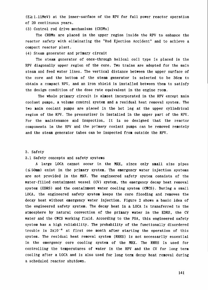
(E^l.llMeV) at the inner-surface of the RPV for full power reactor operationof 20 continuous years.(3) Control rod drive mechanisms (CRDMs)
The CRDMs are placed in the upper region inside the RPV to enhance thereactor safety with eliminating the "Rod Ejection Accident" and to achieve acompact reactor plant.(4) Steam generator and primary circuit
The steam generator of once-through helical coil type is placed in theRPV diagonally upper region of the core. Two trains are adopted for the mainsteam and feed water lines. The vertical distance between the upper surface ofthe core and the bottom of the steam generator is selected to be 36cm toobtain a compact RPV, and an iron shield is installed between them to satisfythe design condition of the dose rate equivalent in the engine room.
The whole primary circuit is almost incorporated in the RPV except maincoolant pumps, a volume control system and a residual heat removal system. Thetwo main coolant pumps are placed in the hot leg at the upper cylindricalregion of the RPV. The pressurizer is installed in the upper part of the RPV.For the maintenance and inspection, it is so designed that the reactorcomponents in the RPV and the primary coolant pumps can be removed remotelyand the steam generator tubes can be inspected from outside the RPV.
3. Safety3.1 Safety concepts and safety systems
A large LOCA cannot occur in the MRX, since only small size pipes(^50mm) exist in the primary system. The emergency water injection systemsare not provided in the MRX. The engineered safety system consists of thewater-filled containment vessel (CV) system, the emergency decay heat removalsystem (EDRS) and the containment water cooling system (CWCS). During a smallLOCA, the engineered safety system keeps the core flooding and removes thedecay heat without emergency water injection. Figure 2 shows a basic idea ofthe engineered safety system. The decay heat in a LOCA is transferred to theatmosphere by natural convection of the primary water in the EDRS, the CVwater and the CWCS working fluid. According to the PSA, this engineered safetysystem has a high reliability. The probability of the functionally disorderedtrouble is 2xl(T6 at first one month after starting the operation of thissystem. The residual heat removal system (RHRS) is not necessarily essentialin the emergency core cooling system of the MRX. The RHRS is used forcontrolling the temperatures of water in the RPV and the CV for long termcooling after a LOCA and is also used for long term decay heat removal duringa scheduled reactor shutdown.
141

Containment vessel
Main steam line(X2)
Watertight shellReactor vesse!
Fig.2 Engineered safety system of MRX
i : Emergency Decay Heat Removal SystemCWCS : Containment Water Cooling SystemRHRS : Residual Heat Removal System
(1) Containment vessel (CV)The design pressure of the water-filled CV is 4MPa to withstand a high
pressure at LOCA. The size of the CV is designed to satisfy the requirementsof radiation shielding and the maintenance of instruments installed in the CV.The RPV is surrounded with a watertight shell for thermal insulation. Theshell can stand against the static pressure at anticipated transients.Pressure relief valves are installed to mitigate the rise of pressure in thespace between the RPV and the watertight shell due to pipe breakage accidentsin this area.(2) Emergency decay heat removal system (EDRS)
The EDRS is a closed system which transfers decay heat from the core tothe CV water. It includes three trains, each of which has a capacity to removethe core decay heat. Each train consists of a hydrogen reservoir tank, acooler, two valves and piping. In the case of accidents, the valves of eachtrain are opened actively by the signal of battery, then the primary coolantcirculates by natural convection removing decay heat from the core and iscooled in the cooler placed in the CV water.(3) Containment water cooling system (CWCS)
The CWCS is a heat pipe system for long term decay heat removaltransferring the heat in the CV water to the atmosphere. It includes fourtrains. In the event of an accident, the water temperature in the CV will bekept lower than the design value by the arbitrary three trains operated usingnatural convection. For its working gas in the CWCS, anti-freezing gas such as
142

R22 (CHCIFz) will be used taking into account of low temperature condition inice-sea atmosphere.3.2 Safety evaluation
Accidents of primary coolant loss, steam generator tube rupture, steamline break, feed water line break and total loss of electricity have beenanalyzed for safety evaluation of the MRX. Figure 3 shows typical resultsduring LOCA obtained RELAP5/Mod2 calculation assuming the double endedguillotine break of 50mm dia. pipe occurred in the CV. Cooling by the EDRS,the CV water and the CWCS is taken into account, but the function of the RHRSis neglected. The maximum design values of pressure and water temperature inthe CV are 4MPa and 200*C as mentioned in Table 1, and the allowable minimumwater level in the RPV is 0.5m above the upper edge of the core, which isdetermined to keep core flooding taking into account of ship inclination andoscillation. Figure 3 shows that the maximum values of pressure and watertemperature in the CV and the minimum water level in the RPV are l.SMPa, 140'Cand 0.8m, respectively. These satisfy the design conditions sufficiently.Through these analyses, it has been proved that the passive safety featuresapplied to the MRX have sufficient functions in the safety point of view.
4. DecommissioningFor nuclear ships, it is essential from the economical point of view to
shorten the time of the maintenance and refueling works. In operation ofnuclear ships, the maintenance and refueling facilities as supporting systemsare very important to make these works shortly, simply and safety. From thisstandpoint, the design study of a one-piece removal method is being carriedout. This method is that the CV with its internals is removed for themaintenance and refueling, and is replaced to another one whose maintenance
200
gl50CO
rolOOCDQ.E£ 50
0
14
12
?10Q. w
Q)3 eW 0
tt) _,*- 4
2
0
.•
Containment water temperature
)<"'y ''''-•A '•., Water level in reactor vessel' \ '"••-.. /
\ Pressure in reactor vessel^^ ^ Pressure in containment vessel
— -*:~-~r~'
3.0
2 5C,,>J
2.o|V
1.5!CD
1 0 to$:
0.5
nn0 100002000 4000 6000 8000
Elapsed time (sec)Fig.3 Typical transient of LOCA in MRX(Double ended guillotine break of 50mm dia. pipe)
143

i—N To Maintenance\f FarilitvFacility
Reactor Containment
Fig.4 Concept of one-piece removal of CV with its internals
and refueling have already been completed. Figure 4 shows the concept of theone-piece removal of the CV with its internals. It is thought that this methodis promising because the integral type marine reactor is relatively small andlight. The merits of this system are: (a) To shorten the days required for themaintenance and refueling. Ships are required to stay in dock about 3 weeksfor these works, (b) To carry out the maintenance and refueling in a largespace of land facility with highly safe, (c) To reuse the reactor after theship's life, (d) To make the decommissioning of the ship easy.
5. Economics and potential marketWhether or not nuclear ship has economic benefit is a fundamental matter
to judge the social incentive to realize the practical use of nuclear ships.To evaluate the economics of nuclear ships, the construction and operationcosts of nuclear and conventional ships have been studied and compared asparameters of the ship's speed, containers' capacity in terms of TEU (Twenty-feet Equivalent Unit), etc. Figure 5 shows the comparison of RFR (RequiredFreight Rate, S/TEU : Operation cost to transport one container) between twocontainer ships of 6,000 TEU and 30 knots (one uses reactors equipped with twoMRXs of total power 348MWth and the other a diesel engine), in case of Asia-North America route, commissioned for 20 years from the year 2015. Thequantity of container transport through this route is the largest among thethe world's three biggest sea routes (Routes of Asia-North America, Europe-North America and Asia-Europe). The crude oil price is assumed to be $36/bbl.averaged within the service period. This figure shows, (a) The capital cost ofthe nuclear ship is about 2 times larger than that of the diesel ship, (b) Onthe other hand, the fuel cost of the nuclear ship is about 1/2 of that of the
144

6,000 TEU, 30 knots Container shipIn commission : 20 years from 2015(excluding cargo handling charge)
Others
EnvironmentalCost
Nuclear Ship Diesel Ship
Fig.5 RFR of 6,000 TEU container ship
2000
IDLU
ccu_DC1750
1500
Type of Ship : 6000TEU Container shipRoute : Asia-North AmericaIn Commission : 20 years from 2015
25
Diesel(with env. cost)
Nuclear
r -.• Diesel,..,-»•*• (without env. cost)
30Ship Speed (knots)
Fig.6 RFR as a function of ship speed
35
diesel ship, (c) The environmental cost of the diesel ship accounts for 22% ofthe RFR. The cost study of nuclear and conventional ships shows that thesituation becomes more favorable for nuclear ships as increasing of the speedand the load. Figure 6 indicates the RFR as a function of ship speed. Over 28knots, the nuclear ship holds an economically dominant position over thediesel ships, because the diesel ships must have higher environmental costs.
145

6. R&D workTo realize nuclear ships with commercial use, it is necessary to obtain
an economical, safe and reliable reactor system. In addition, thesupplementary items such as the international agreement on safety, thepreparation of the maintenance yard, etc., should be solved. R&D programs onnuclear ships have been proposed and being performed to solve technicalsubjects so that the nuclear ships will be put into commercial use in thefuture.(1) Experimental study on thermal-hydraulics
To study the hydrothermal behavior in the water-filled CV, especiallysteam condensation characteristics, a small scale test facility (volume ratio: about 1/300 of MRX) has been fabricated and fundamental experiments on thefollowing behavior are in progress'6', (a) thermal and hydraulic responses inboth the RPV and the water-filled CV under LOCAs, (b) evaluation of mechanicalloads generated by LOCAs, and (c) capability of natural circulation and decayheat removal. Furthermore, to confirm the function of the safety features suchas an integral PWR with a water filled CV and passive safety systems, a largescale synthetic test facility is planned. The thermal power of the facility is5MW (1/20 of the MRX), however the height is same as that of the MRX becauseit is most important to simulate accurately the natural circulation condition.Experiments on board are planned to obtain the behavior under the shipinclination and oscillation.(2) Development of components
The components of in-vessel type CRDMs such as the motor, the latchmagnet, etc., have been developed <6>, and the function and reliability testsusing the full mock-up CRDMs are planned. The water-proofed design is beingperformed for the components and the thermal insulator placed in the water-filled CV.(3) Automatic control system
It is important to reduce the number of reactor operators from the viewof the ship's economy. From this standpoint and to enhance the ship's safety,highly automated control systems have been studied which will be adopted andwill cover the whole operations during normal, abnormal and accidentconditions. This system consists of control and diagnostic systems as shown inFig. 7. The control systems generate control signals for control equipments,for example, control rods, pressure control valves, flow control valves, etc.,in accordance with the reference signals (demand signal) and signals of eachmeasured parameter. If a difference exists between the signals of thereference and the parameter, a control signal is generated based on theoperational procedure and changes the parameter to the demand conditions. Thediagnostic systems are provided to monitor the malfunction of the systems and
146
Operational Limits
Control Systems Control Signals
Operational Procedurestepl : Optimization based on Operator Knowledge Basestep2 : Adaptive & Learning AI Application
Diagnostic Systems
Alarm & Protection Signals^)
Fig.7 Advanced automatic control system for MRX
the plant operating conditions. For the operational procedures, theoptimization is made based on the operator's knowledge and the learning AI.(4) Development of nuclear ship simulator
The nuclear ship simulator NESSY (Nuclear Ship Engineering SimulationSystem) has been developed in JAERI and used for the simulation of the nuclearship "Mutsu" so far<7:>. It can simulate both the behaviors of the reactorsystems and the ship motions. Mutual interactions can be analyzed for thesituations such as changes of the reactor power, the steam generator waterlevel, etc., due to the ship motions caused by waves or the navigator'smaneuvering.
The accuracy of the system has been verified with the operation data ofthe "Mutsu" and it is proved that this system is a very useful tool fordeveloping advanced marine reactors**'. Modifications of the models and theparameters are being made for the MRX reactors since 1995.
1. ConclusionAn advanced marine reactor, MRX, has been designed to be more compact and
lightweight with enhanced safety. The engineered safety is accomplishedthrough a simplified system which is suitable in particular for a marinereactor, since it must be operated by limited number of crews. The LOCAanalysis shows that the core flooding is maintained passively even taking intoaccount the ship inclination. The one-piece removal method is proposed to keepthe maintenance and refueling works short and safe. This method also makes theship's decommissioning easy and enables us to reuse the reactor after the
147
ship's life. The economic evaluation shows that for container ships of 6000TEU traveling over 28 knots, the nuclear ships will hold an economicallydominant position after 20 years from the present time, because the dieselships must have higher environmental costs. In addition to the design study,extensive R&D activities are being performed. These can contribute largely tothe realization of the nuclear ship in commercial use in the future.Considering that the MRXs are small size reactors with highly safecapabilities and transferable ones, they have a wide variety of uses in theenergy supply system.
Reference(1) A. Yamaji and K. Sako : Shielding Design to Obtain Compact Marine Reactor,
J. Nucl. Sci. Technol., Vol. 31, No. 6, 1994.(2) K. Sako, et al. : Advanced Marine Reactor MRX, Int. Conf. on Design and
Safety of Advanced Nuclear Power Plants, Oct. 1992, Tokyo, Japan.(3) T. Hoshi, et al. : R&D Status of an Integral Type Small Reactor in
JAERI, ICONE-3, Apr. 1995, Kyoto, Japan.(4) A. Yamaji, et al. : Core Design and Safety System of Advanced Marine
Reactor MRX, ibid.(5) T. Kusunoki, et al. : Steam Condensation Behavior of High Pressure Water's
Slowdown Directory into Water in Containment under LOCA, ibid.(6) Y. Ishizaka, et al. : Development of A Built-in Type Control Rod Drive
Mechanism (CRDM) for Advanced Marine Reactor MRX, Int. Conf. on Design andSafety of Advanced Nuclear Power Plants, Oct. 1992, Tokyo, Japan.
(7) T. Kusunoki, et al. : Development NESSY (Nuclear Ship EngineeringSimulation System) and Its Application to Dynamic Analysis, ibid.
(8) M. Ochiai, et al. : Present Status of Nuclear Ship Engineering SimulationSystem, The 1994 SCS Simulation Conference, Apr. 1994, San Diego, U.S.A.
148

CONCEPT, EXPERIMENTAL AND CALCULATIONAL XA9745982INVESTIGATIONS OF A MICROMODULE REACTOR
Yu.I. OREKHOV, R.S. POMET'KO, Yu.A. SERGEEVInstitute of Physics and Power Engineering,Obninsk, Kuluga Region,Russian Federation
Abstract
In addition to the evelutionary improvements and development of new additional devices andsafety systems, much prominence is now given to the search of technical principals providingthe enhanced safety for a NPP using new reactor design concepts as a whole. One of suchconcepts refers to the experience of the Institute of Physics and Power Engineering (IPPE),accumulated in the area of the exploitation of reactor channel loops for research purposes.A long-term experience of using such loops reveals that they feature a high reliability, safetyand high technical and engineering parameters.
Introduction
In addition to the evelutionary improvements and development of new additional devices andsafety systems, much prominence is now given to the search of technical principals providingthe enhanced safety for a NPP using new reactor design concepts as a whole. One of suchconcepts refers to the experience of the Institute of Physics and Power Engineering (IPPE),accumulated in the area of the exploitation of reactor channel loops for research purposes.A long-term experience of using such loops reveals that they feature a high reliability, safetyand high technical and engineering parameters.
1. Reactor Concept
The concept suggested consists in subdividing the primary circuit of a reactor in smallvolumes with minimal hydraulic connections between each other. This concept is realizedby employing devices of special construction, the so-called micromodules (MM). Amicromodular channel is a tubular pressure vessel (Fig.l) 100-200 mm in diameter, wherea fuel assembly is positioned in its lower part and a heat exchanger (HE) (1-2 circuits) in theupper part. Using flow splitters, the natural circulation of coolant is maintained in theprimary circuit of the MM. Each micromodule is provided with inlet and outlet pipelines forsecondary circuit coolant and with a pipeline connecting the MM primary circuit with thepressurizer (P). Thus, from the viewpoint of the construction and thermal-hydraulic scheme,the MM is a miniature integral reactor. To provide a prescribed reactor power, the core iscomposed of the necessary number of micromodules which are inserted in the moderator(e.g., graphite, heavy water, etc.).
Qualitative analysis and quantitative estimations obtained in late 1970's and early1980's revealed that based on the above mentioned concept, the creation of a reactor ofenhanced safety is possible at the expense of the following factors:
The subdivision of the primary circuit in a number of small independent volumes(up to 100 1), resulting in reduction of the scales and accident consequences due to the
149

depressurization in the primary circuit. In the event of the MM vessel rupture, the heatremoval from fuel assemblies is accomblished due to water inflow from the pressurizer andthen due to water supplied by feed pumps.
The absence of circulation lines of large cross-sections in the primary circuit: in thecase of the rupture of the small diameter (about 10 mm) pipeline connecting the MM withthe pressurizer, the reliable cooling of fuel assemblies will be provided during a long-periodof time at the cost of possible steam condensation in the-micromodule heat exchanger.
The limited velocity and amount of coolant discharge while disrupting the primarycircuit, makes the problem of the accident loca.lization within a plant easier.
The compactness of the MM primar.y circui t creates ideal conditions for the naturalcirculation (NC) in the circuit in each flow regime.
In the case of channel reactors, it is easier to solve the problem of organisingindependent (autonomic) cooling system for control rods in the MM-based reactors. Thissystem can operate as an additional channel for heat removal in case of failure of major heatremoval systems.
In view of the fact that the MM power and correspondingly, its cross-sectionaldimentions are dozens and hundreds times lower than the reactor power, there exists a realpotentiality to conduct experiments on different operation conditions, accident conditionsincluded, using electrically heated modules of the fu l l scale hight.
The above given considerations stimulated the development of a reactor based on theproposed concept.
2. project of Micromodule-Based Reactor
In the 1980's, the Research and Development 1 nstitute of Power Engineering (RDIPE)together with the Institute of Physics and Power Engineering (IPPE) has developed a numberof reactor designs (with a capacity from 20 to 300 M W) for the Nuclear District Heat Plant.Fig.2 shows the schematic diagram of a reactor, and Table 1 incorporates the mainparameters of the RKM-150 unit, for which the technical design and extensive calculationaland experimental investigations were performed. Alongside with the concept consisting insectioning the primary circuit into small volumes, the MM- based reactor safety is guaranteedby a set of other factors:
Self-protecting features of the reactor: negative power, temperature and steamreactivity coefficient: the stability of the power generation field; - high heat capacityof reactor; -natural circulation of water in the primary circuit.
The availability of safety systems: - reactor shutdown by introducing absorbersunder the action of the force of gravity; - the micromodule replenishment with waterduring the vessel rupture from the pressurizer (passive) and then by pumps; thecirculation of the secondary circuit with water from hydroaccumulators (passive) andthen by pumps; heat removal from the MM by the evaporation of water from tanks(passive) via the water cooling tower (active) or to the network circulation loop(active).
150

, TABLE 1. MAJOR CHARACTERISTCS OF THE RKM-150 REACTOR
CHARACTERISTICS, UNITSThermal power, MWReactor Core-moderator-MM number-number of controls-height , mMicromodule
— power . kWoveragemaximum
-number of fuel elements-ir, a fuel assembly,-heat removal surface of the fuelassembly, m2
-vessel diameterin che core, mm x rr.r..in the heat exchanger region
-lull height, mmPrimary circuit water parameters-pressure, MPa-temperature, °C
at the fuel assembly inletat the outlet of the fuel assembly ofmaximum power
-flow rate in the MM at maximum power-the number of pressurizersHeat exchanger 1-2 of the circuit-the number of Field tubesheight, m-heat transfer surface, m2
Secondary circuit water parameters-pressure, MPa-inlet and outlet temperature , °C-flow rate, t/hrNetwork circuit parameters-pressure, MPa-inlet and outlet temperature, °C-flow rate, t/hr
VALUE150
graphite220443
6621070
'-> r .
3 85lie 5 •;180 , 1010690
7 351362651 64
373
6.3
1.1880/1402130
1.670/1302135
151

By additional technical solutions: moderate parameters (the heat fluxes of fuelelements, pressure, temperature); independent cooling system for absorbing rods; a goodthermal contact between the MM vessel and graphite; pressure relation in circulating loopsP! >P2<P3 , etc.
3.ComputationalStudy
The experimental investigations using MM models were preceded by numerical onesmainly aimed at the selection of geometric and operating regime parameters for the MM andreactor unit as well as the prediction of their behaviour under accident conditions. In theprocess of calculations for normal operating conditions, the limiting MM power value wasobtained and the dynamics of natural circulation development at varying power, etc. weredetermined.
Calculations were also performed for typical accidents such as the disrupture of thepipeline between the MM and the pressurize, the MM vessel failure and others. In view ofthe complexity of hydrodynamical and heat transfer processes under such condition someproblems should be experimentally verified. These questions wi l l be touched upon laterwhen discussing experimental data in Section 4 and now we shall consider some calculationalresults for beyond-design accidents in more detail.
In a beyond-design accident with postulated instantaneous MM uncovery, under thereactor emergency shutdown conditions, the maximum fuel temperature at a fuel assemblypower of 1070 kW was 1070 C. The fuel melting takes place when the pipeline connectingthe MM with the pressurize breaks just near the MM vessle with the simultaneous failure ofthe reactor emergency protection or when the MM vessel breaks simultaneously with theemmergency protection system failure and the disrupture of the pipeline between the MM andpressurizer. In both cases, the fuel melts only in one MM subjected to the failure.
In beyond-design accidents accompanied by the failure of secondary circuit heatremoval systems, the absorber cooling system ensures that the maximum fuel elementcladding (12OO C) was not exceeded. If this system fails also, the element temperature of1200 C is riched for ~ 12 hours because of the large heat capacity of the reactor. During thistime it is necessary to take adequate measures to monitor the accident process. Table 2 givesan idea on the radiation exposure as a consequence of different normal and accidentconditions.
TABLE 2. YEAR EFFECTIVE EQUIVALENT DOSE VALUESON THE BOUNDARY OF THE SANITARY-PROTECTION ZONE (2 Km)
SITUATION
Normal operationDesign accidentsBeyond designaccidents
Designvalues , Zv/year
7.6 x 10 ~86.6 x 10 8
4.1 x 10"3
Tolerablelimits, Zv/year
2 x 10"40.10. 1
152

4.Experimental Study
To study the MM thermal-hydraulics, two electrically heated full scale models weredesigned and manufactured in the Institute of Physics and Power Engineering: of high (upto 10 MPa) and low (up to 1 MPa) pressure. Both models practically are entirely analogousto the standard micromodule design (Fig.l). The first model was used to validate workingdesign parameters and investigate a number of accident senarios. The second one wasemployed to study the temperature behaviour of fuel elements at the final phase of accidents.In the latter case, the heat flux simulation from the graphite moderator was also provided.
4.1.Steady-State Conditions
At the first stage of investigations, the effort was mainly concentrated on thevalidation of the design of the MM parameters, among which the coolant flow rate in theprimary circuit under natural circulation conditions is most important.
In Fig.3 the flow rate in the primary circuit, G, versus the fuel element power ispresented at high pressures. In the single phase flow region (N < 800 kW, P, > 5.0MPa), the flow rate G , does not depend on the pressure in the primary circuit. Withfurther increasing of power, the appearance of a steam phase raises the rate of circulationearlier the lower the pressure. With a design pressure value of 7.85 MPa and a maximumpower-rating channel capacity of 1070 kW, the coolant is subcooled and boiling (even surfaceboiling) is actually absent. In this case, the flow rate over the primary circuit reaches Gi =1.5 kg/s which is in fair agreement with the design value of the standard micromodule flowrate (1.6 kgls). It should be noted that for the MM design parameters, the flow rate is foundto be stable. Only with reduced pressures (~ 2.5 MPa) in the primary circuit, minor flow ratevariations appeared within a narrow range.
4.2.Dynamics of Micromodule
With the natural circulation of water in the primary circuit, the flow rate increases as thepower rises. There was a danger that this circumstance will restrict the rate of the MMpower increase due to a slow increase of the flo\v rate to a new (increased) value or initiatethe circulation instability.
Experiments have eliminated this possibility. In the case of a momentary raise of thepower from initial values of 100, 300 and 550 kW by 200 kW, the set-up of a new flow ratevalue occures smoothly and readily (for < 1 min) . Thus, the natural circulation is not afactor which could hinder providing the reactor with the necessary manoeuvre characteristicsin the process of its operation as a part of a District Heat Plant.
4.3.Accident Regimes
4.3.1.Depressurization of Primary Circuit
While studying accident situations, the major attention was focused on accidents associatedwith the depressurization of primary circuit components and the disturbance of heat removalover the secondary circuit.
153

4.3.1.1.Rupture of the pipeline between MM and pressurizer
Consider the behaviour of the MM channel in the case of the disrupture of the pipelineconnecting the micromodule with the pressurizer. The peculiarity of this situation is that itis impossible to feed water to the MM from the pressurizer. The calculations obtained forthis accident did not predict severe consequences; however, this fact needed an experimentalverification. The problems to be studied were as follows:
- The MM depressurization results in ceasing or reversing of the circulation in theMM or degrading the heat removal from fuel elements in the first phase of the accident;
- the amount of water remaining in the MM compared to the amount at the momentthe pressure reduces up to the atmospheric value in it;
- the maximum permissible power of the fuel assembly filled with water under theflooding conditions (zero flowrate);
- the rate of coolant losses at the final accident phase at a pressure near to theatmospheric.
Fig.4 shows the results of one of the experiments investigating the break-down of the pipelineconnecting the MM with the pressurizer. The rupture is located just in the vicinity (100 mm)of the MM vessel and is simulated using a fast-responce device. The initial power of thechannel amounted to 1070 kW and then reduced according to the law of residual heatvariation. The delay time was accepted to be 10s. which is considerably heigher than thedesign-basis value (i.e below 1 s).
The experiments indicated that the pressure in the MM reduces to the atmosphericpressure for 1-2 min. The water flow rate through the fuel assembly slitly increases at thebeginning of the process (to - 1.9 kg/s) and then for 2-2.5 min is practically equal to thenominal one (1.5 kg/s), providing the reliable cooling of fuel elements. No negativeoutcomes were found in the temperature behaviour of fuel elements over this time period.
The amount of water remained in the MM to the moment of reducing the pressure tothe atmospheric value amounted to 54 kg., the water level being ~ 2.6m above the upper edgeof the fuel assembly.
To define the limiting fuel assembly power under sarbotage conditions occurring afterreducing the pressure, some preliminary tests were carried out using a 7-rod bundle with theinlet cross-section blocked, (i.e. under more severe conditions as compared to the MM).They revealed, that for a 30-rod fuel assembly MM the limiting power should be 120-130kW, thich is higher than the net power of the residual heat in fuel elements and the heatinflux from graphite (for the present 100 kW design). In the full scale MM without blockageat the fuel assembly inlet (i.e. for real conditions) at the atmospheric pressure, a power of150 kW was reached without any indications of an> critical phenomena. Thus, the conditionof the fuel assembly filled with water is sufficient to remove the residual heat under no-crisisconditions.
After the MM pressure is reduced to the atmospheric value, the further developmentof the process is characterized by the ongoing loss of coolant. The presence of the heatexchanger in the MM results in that the overwhelming portion of steam generated in the fuelassembly condenses on the surface of this heat exchanger and returns through thedowncomming line of the circuit to the fuel assembly inlet. As a result, the rate of steamlosses through the rupture is considerably lower than the rate of steam generation in the fuel
154

assembly. The measurement of the rate of mass losses in this phase of the accident is takenat different values of the fuel assembly power, and different levels of water in the MM.The obtained data allowed the time interval to be defined, over which the fuel assembly hasreliable cooling, and the fuel element cladding temperature is close to the saturationtemperature of water at the atmospheric pressure This time interval ranges from 36 to 44hrs, and only then the fuel element heat-up w i l l occur, but no higher than 610 C inaccordance with the calculations
4.3.1.2.The Micromodule vessel rupture
While breakage of the MM vessel, and the link between the MM and the pressunzer remainsintakt, the MM is provided with water from the pressurizer. However, with a large breakof the MM vessel, the flow rate of the loss of coolant exceeds the flow rate of the supply;therefore the pressure and the amount of the coolant in the MM decreases until the amountsof losses and supplied l iquid are equal
To study such the situation, the MM vessel was prov ided with pipe connections of which thebreaks at different elevations were simulated (i.e 5190 mm and 1140 mm above the upperedge of the fuel-assembly) All experiments were conducted at an initial power of 1070 kWreducing in accordance with the residual heat expeaed.
It is experimentally established that if the disrupture of the MM vessel occurs at these elevations inthe initial phase of the accident, the heat removal from the fuel assembly is effected in crisis-freeconditions with the fuel assembly filled with water Therefore the subsequent cooling of the fuelassembly is beyond question even if only the feed is present in these cases. The contrary is the casewhen the MM vessel ruptures below the fuel assembly where the MM is incapable to retain the suppliedwater and the flow rate entering it from the pressurizer is insufficient to provide a continuous flow overthe entire fuel assembly cross-section. It is possible under these conditions that water will not flowaround a portion of the fuel elements, which wil l lead to their overheating.
The experiments were conducted as follows: A preset flow rate of water ot room temperature (15-20OC) was fed to the upper part of the micromodule, then the power of a predetermined value wassupplied to the fuel assembly and the micromodule vessel; the fuel element temperature being recordedat four points over the fuel assembly cross-secuon and at ten points of the entire elevation.Considerable attention was paid to the investigation of the influence of the feed water conditions (e.g.below or above the "flow-over" windoiqs of the lieat exchanger; from one or two sides of the MMvessel) Tables 3 and 4 present some results of these experiments It is obvious from Table 3 that thereis a significant scatter in tuel assembly temperature (65-400°C) This shows a non-uniform distributionof inlet water over the tuel assembly cross-section. Of great interest is the fact associated withreduction of the fuel element surface temperature as the power increases from 10 to 15 kW in thepresent case. To our mind, this is due to the boilmg-up of water on those simulators where water isavailable, and its more uniform distribution over the fuel assembly cross-section At a certain stage,further increase in power logically results in a rise ot the rod temperature
With increasing the flow rate of water being ted to the MM low tuel assembly temperatures areobserved at sufficiently high powers (Table 4) In the RKM-150 reactor, the parameters of waterflowing around the secondary circuit and the net MM power (together, with the heat influx fromgraphite, amounting to ~ 40 kW) meet the conditions ot the test the results, ot which are shown in thesecond column ot temperatures, Table 4. Howe\er in the RKM-150 reactor the flow rate of water
155
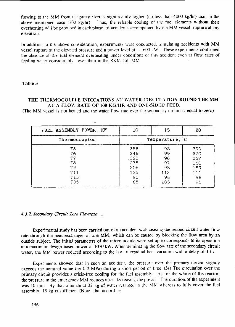
flowing to the MM from the pressurizer is significantly higher (no less than 4000 kg/hr) than in theabove mentioned case (700 kg/hr). Thus, the reliable cooling of the fuel elements without theiroverheating wil l be provided in each phase of accidents accompanied by the MM vessel rupture at anyelevation.
In addition to the above consideration, experiments were conducted, simulating accidents with MMvessel rupture at the elevated pressure and a power level ot ~ 600 kW. These experiments confirmedthe absence of the fuel element overheating under conditions ot this accident even at flow rates offeeding water considerabh 'ower than in the RKM-150 MM
Table 3
THE THERMOCOUPLE INDICATIONS AT WATER CIRCULATION ROUND THE MMAT A FLOW RATE OF 100 KG/HR AND ONE-SIDED FEED.
(The MM vessel is not heated and the water flow rate over the secondary circuit is equal to zero)
FUEL ASSEMBLY POWER, KWThermocouples
T3T6T7T8T9TilT15T35
10 15 20Temperature , ° C
358346.3202753061359065
989998979811398105
3993703671601591119898
4.3.2.Secondary Circuit Zero Flowrate ,
Experimental study has been carried out of an accident with ceasing the second circuit water flowrate through the heat exchanger of one MM, which can be caused by blocking the flow area by anoutside subject. The. initial parameters of the micromodule were set up to correspond- to its operationat a maximum design-based power of 1070 kW. After terminating the flow rate of the secondary circuitwater, the MM power reduced according to the law of residual heat variation with a delay of 10 5.
Experiments showed that in such an accident, the pressure over the primary circuit slightlyexceeds the nominal value (by 0.2 MPa) during a short period of time 15s) The circulation over theprimary circuit provides a crisis-free cooling for the fuel assembly As for the whole of the reactor,the pressure in the emergency MM reduces after decreasing the power The duration.of the experimentwas 10 mm By that time about 32 kg of water re ta ined in ihe MM \\hereas to fully cover the fuelassembly, 18 kg is sufficient (Note, that according
156

Table 4.
FUEL ELEMENT TEMPERATURE AT WATER CIRCULATION AROUND THEMM WITH A FLOW RATE OF 720 KG/HR (ONE-SIDED FEED.
(The water flow rate in the secondary circuit is 11 t/iir and inlet temperature is - 65 C)
Fuel Assembly Power, kWVessel Power, kWTotal Power, kW
ThermocouplesT3T5T6Til -T24T35
1020102
6040100
6020 .80
Temperature, °C10793107104109105
10367104103106103
1055510396104102
to calculations, the time required to decrease the water amount in the MM to 18 kg is 13 min).Thus the experiment reasonably well justified the predicted t ime of start ing the fuel assemblyuncover, which is assumed in the fuel element temperature behaviour evaluations.
4.4.Thermal-Hydraulic Characteristics
One of the possible trends in further improvement of the reactor of the proposed design is to usea micromodule with boiling water in the primary circuit. Fig.5 illustrates the experimental results ofan experiment in which the micromodule is filled with water to a certain level (V= 90, 80 and 65%of the total free micromodule volume) and cut off the pressurizer. Thus, the pressure balance underheating-up conditions is due to the gas (steam-gas) volume being in the upper part of the micromodule.It is evident from the figure that a micromodule power of 1070 kW can be reached with V0= 80% ata pressure of 5.3 MPa. With filling V0 = 65 %, such a power is reached at a pressure of 3.3MPa; thecoolant flow rate of the primary circuit with boiling water in both cases being higher than under thenon-boilin conditions. It is necessary, however, to note that flow rat fluctuations were observed in arestricted range of powers (e.g. with a amplitude of 1.5 % at V 80 % within the range of power from250 to 350 kW and 15 % with V = 65 % at a power up to 150 kW.
4.5. In-Pile and Other Tests
one of the conditions of the reactor reliability and safety is the favourable water-chemicalconditions for the construction materials. The traditional measures of water purification and theintroduction of correcting agents in the MM reactor being the "blind" part of the loop are practicallyimpossible.
The study of the water-chemical conditions was performed using MM models under in-pileconditions. All in all 5 micromodules were tested in the reactor of the First Nuclear Power Station.In total, the time of operation during testing amounted to about 150 000 days and nights. The duration
157

of the operation of four micromodules amounted to about 10 years for each of them. The main resultsof experiments are as follows:
- while filling the gas space of the pressurizer with nitrogen, the ammonia synthesis takes placein the water of the primary circuit and the pH value is set up at a level of 9-11;
- the content of corrosion products in stainless steel is on the average - 0.15 mg/kg for iron, fornickel and chrome it was 20 mg/kg;
- the amount of chlorides does not exceed 0 05 mg/kg. The amount of gasses amounts to 30-150H.cm5 /kg;
After 5 years of testing, one of the micromodules was withdrawn out of the reactor to assess thecorrosion condition. The visual inspection showed that the fuel elements and the MM vessel are in asatisfactory state. No mechanical damages of fuel elements and spacing grids were detected and novisible depositions were present on the fuel element surfaces. After examination, this MM was placedagain into the reactor, where it operated for about 5 years more.
In addition to the above mentioned studies, the work was performed on a number of directionsof supporting the RKM-150 reactor design. They included comparative experiments on enhancing theabsorbing materials control rods system. The best results were obtained with usimg Dl/2 Ti O5 whichwas adopted in the technical design of the reactor
Also, the problems of the fuel element cladding tightness control system were studied. It wasfound that such a control, which does not require sampling the coolant can be implemented usinggamma-ray detectors being moved between the micromodules in the above-reactor space, when thereactor is shut down.
Conclusion
1. The concept is proposed to enhance the reactor safety at the cost of subdividing the primary circuitinto small parts. This is achieved by means of micromodules incorporating a fuel assembly, a heatexchanger and a natural circulation of coolant.
2. Wide experimental and computational investigations confirmed the design characteristics of such areactor (RKM-150) regarding:
The therrnohydraulics involving the temperature regimes;flow rate and natural circulation stability;thermal core safety under the natural circulation;the water-chemical condition;the manoeuvrability in var.-Ing the power uunng load variation;and the correspondence to the nuclear and radiative safety requirements.
158

SPECIFIC SYSTEMS AND ANALYSIS

EMERGENCY HEAT REMOVAL IN THE INTEGRALWATER COOLED ABV-6 REACTOR FOR THEVOLNOLOM FLOATING NUCLEAR POWER PLANT
Yu.D. BARANAEV, Yu.I. OREKHOV,Yu.A. SERGEEV, I.M. SHVEDENKOInstitute of Physics and Power Engineering,Obninsk, Kuluga Region
Yu.P. FADEEVOKB Mechanical Engineering,Nizhny NovgorodV.M. VOROBYEVCDB Baltudoproject,St. PetersburgRussian Federation
Abstract
Several independent active and passive safety systems are employed in the design ofintegral WCR in order to provide together with the reactor inherent safety featuresrealization of the emergency heat removal function:- active primary coolant clean-up system transmitting heat to the tertiary and then to theforth circuit,- passive emergency heat removal through steam generator to the atmosphere,- reactor cavity flooding system providing heat transfer from the reactor vessel to thereactor metal-water shielding tank,- high and low pressure make-up system using water from the special storage tank.
Operation of the systems under LOCAs and accidents with normal heat removal systemsfailure is considered in the paper. Special emphasis is done to the description of systemscharacteristics, systems interaction and modes of operation which are influenced by thereactor integral design.
Emergency heat removal (EHR) is one of the major safety functions that shouldbe provided by the design of reactor safety systems.
Under the design of the ABV-6 reactor designated for the floating NPP "Volnolom"the following specific features of the reactor were taken into account:- Integral reactor design (Fig. 1)- Low reactor capacity (38 MWt)- High reactor heat accumulation capability (-1.8 s per °K)- Natural convection in the reactor primary circuit
161

- High margin in the strength characteristics of the primary circuit equipment (tolerablepressure of 31 MPa is ~2 times higher than the nominal design pressure)
- Employment of metal-water shielding tank containing 26 m-^ of water- High thermal conductivity of reactor fuel made of iiranium-alurninum alloy.
These features of the ABV-6 reactor strongly influence the solution of the EHRissues.
1. The integral arrangement of the primary circuit results in exclusion of big primarypipelines as well as a larger primary coolant inventory in the reactor pressure vessel(RPV). These result in long period before it is necessary to start coolant supply to theRPV under LOCAs, since reactor core uncovery in the case of reactor make-up systemfailure would take place only several hours after the beginning of the accident. Besides,there is a possibility for the EHR through steam-generator in integral reactor design andthis also enlarges the grace period.
2. The relative portion of heat dispersed to the surroundings is higher at smallreactor capacity. This allows decrease in the time required for the EHR systems tooperate.
3. The high reactor heat capacity allows reduction of the EHR system capacitycompared with the residual heat rate. The excess of extracted heat is accumulated in thereactor primary coolant and structures in the first stage of the accident withoutunacceptable reactor temperature and pressure rise.
4. Natural convection ensures reliable heat removal from the reactor core withsufficient departure from nucleate boiling margin during transient and accidentconditions.
5. Large margins in the strength of the primary circuit together with high heatcapacity of the reactor ensure tightness of the primary circuit under accidents with failureof all EHR trains for a long period of time. For some beyond the design basis sequencesthis time is unlimited.
6. The metal-water shielding tank is an effective heat sink. The amount of water inthe tank is sufficient to provide the EHR for 3 days.
The ABV-6 reactor plant is equipped with the following systems that can be used forthe EHR:- Active two trains system supplying water to the steam generator (SG) from the feedwater storage tank (48 m^ ) by the emergency feed water pumps with a flow rate up to 15m3/h each (Fig.2).
- Passive two trains system supplying water to the steam generator from pressurizedstorage tanks containing 4 m^ of water (Fig. 3).
- Active primary coolant purification system with pump and heat exchanger designed toremove 1370 kW (3.3% of reactor rated power) of heat directly from the primary water(Fig.4).
- Active two trains emergency core cooling system (ECCS) supplying water to the reactorvessel by 3 high-pressure (head 17 MPa, flow rate 1.2 nP/h each) and 2 low-pressure(head 3.5 MPa, flow rate 20 m^/h each) pumps (Fig.5).
162

ABV-6 reactor
Control rod drivemechanism
Closure headassembly
Reactor pressure vessel
Steam generator
Removable Internalsassembly
Core
163

Engineered emergency residual heat removal system
RHR condenser ^.^
Feedwater storage tanks
T to turbineX plain
VI from i' ERHRS
to mainfeedwatersystem
from mainfeedwateisystem
Emergencyfeedwaterpumps
2.
164

Passive emergency residual heat removal system
to atmosphere
to steamgeneratorsectionsturbine plant
Fig. 3.
165

Channel for heat removal throught purification system cooler
111 circuit expansionLank
IV circuit
FV circuit'
Metal-water sh'riding tank
Coolant purification andcooling system cooler
Fig. 4.
166

Emergency core cooling system
Make-up uaier tank
t'rom waterpicpanng system
Leakagecontrolcvhndcr
-{hifrom bubbler Fccdv. alcr stoum.-
from liquiabsorber lank
jjfi pumps %
to purification andcooline svstcm
DN32
Ball isolation valve
Stand-byfcedwatci V -pumps L, ~
167

Reactor vessel emergency cooling system
Gas supply (removal)
P
Pig. 6.
168

TableABV-6 REACTOR SAFETY CHARACTERISTICS UNDER BDBA
Initialevent
Safety systems failure Accident characteristics
Black-out One train of passiveEHR failure
Reactor pressure drops from 15.4 MPa to 13.5 MPa by the moment ( 3.5 h ) of depletion ofhydroaccumulator. Further on the pressure increases up to 25 MPa in 36 h and then it goes downthanks to dispersion of heat to surroundings. The tightness of primary circuit is kept.
Two trains ofpassive EHR failure
Reactor pressure goes up reaching the primary circuit strength limit ( 31 MPa ) in 5 h. Withoutoperator actions control rod drive sealing failure takes place.______________________
Scram failure Negative feedback shut the reactor down. Passive EHR system starts to operate in 2 min at thepressure of 18.7 MPa. By the moment of the pressurized water tanks depletion ( 3.5h ) theprimary pressure drops to 15.7 MPa and then increases up to 29.2 MPa in 27 h. The tightness ofprimary circuit is kept.________________________________________
Pressurizerpipeline break
One train of the ECCSfailure
One high pressure pump is sufficient to prevent core uncovery. Minimal water volume above thecore is 1 m-^ even in case of only high pressure pump operation and is 2 m^ if low pressurepump operates.____________________________________________
Two trains of the ECCSfailure + failure of heat
removal through the SG
Core uncovery in 3 h.Beginning of FP release from the fuel in 4.5 h.Core melt in 7.2 h.Maximal RPV temperature does not exceed 710 °C if the reactor cavity flooding is providedduring the core melt. If not, the RPV temperature reach 1200-1300 °C. The RPV melt through isprevented anyway.If the EHR through the SG takes place core uncovery starts in 10 h and all further processes goslower.

- Passive reactor cavity flooding system with a pressurized water tank up to 7 MPacontaining 1.2 m^ of water (Fig. 6).
Safety analysis for all initial events considered has demonstrated a high level ofreactor safety system effectiveness and sufficiency under design and beyond the designbasis sequences. Some results of the safety analysis are shown in the Table.
It is reasonable to add that according to the PSA, the frequency of black-out withsimultaneous failure of two passive EHR system trains does not exceed 10'10 per reactor-year. Cumulative frequency of core melt was assessed as 2.5*10'7 per reactor-year.
The above information allows the conclusion that the integral design conceptprovides broad range of opportunities to enhance reactor safety with reliance on clearand simple design solutions. This concept looks rather promising at least for smallwater-cooled reactors.
170

HIGHLY EFFICIENT CASSETTE STEAM XA9745984GENERATOR FOR INTEGRAL REACTORS
P.M. MITENKOV, V.M. RULEVOKB Mechanical Engineering,Nizhny Novgorod,Russian Federation
Abstract
A once-through cassette steam generator for an integral reactor is considered. Thesteam generator consists of separate cassettes and is arranged in the annulus betweenthe reactor vessel and the core barrel. Specific developments of integral reactor designsshow that the technical feasibility of their implementation is determined to a substantialdegree by the characteristics of steam generator used. This paper describes a steamgenerator with improved overall and thermotechnical characteristics compared to existingsteam generators. The high specific characteristics of steam generator allow developmentof an integral reactor for 600 MWe NPP.
1. INTRODUCTION
Integral reactors characteristics depend greately on the characteristics and structureof the steam generator.
Power rise of integral reactors is limited due to the low specific power of the existingsteam generators, in particular those made of helical tubes.
The necessity to locate steam generator inside the reactor vessel causes someadditional requirements on its structure, the most important of which are high compactnessof the heat exchange surface and high specific power of the steam generator.
OKBM has developed various types of once-through SGs being operated in marinereactor plants PWRs. These SG types, in particular, include:
1) SG made of helical tubes;2) Cassette-type SG made of straight tube steam-generating elements.It has been proven by numerous experiments that the specific design of cassette-
type SGs with straight steam-generating elements has better specific characteristicscompared to SGs with helical tubes other conditions being equal.
For example in the operated cassette steam generators, developed by OKBM specificpower in the effective heat-exchange zone reaches 60 MW/m3.
The design of cassette steam generator for VPBER-600 reactor is considered inthis report.
2. STEAM GENERATOR CONCEPT
When developing the SG for the VPBER-600 reactor special attention was paidto design decisions, which ensure:
1) high reliability requirements;2) operation and repair safety;3) possibility for inspection during fabrication, including 100% non-destructive
testing of materials and welds;171
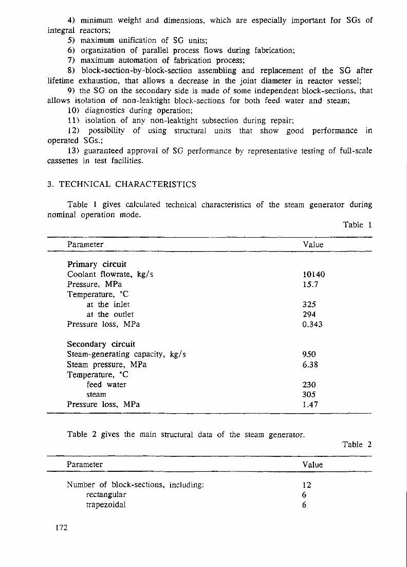
4) minimum weight and dimensions, which are especially important for SGs ofintegral reactors;
5) maximum unification of SG units;6) organization of parallel process flows during fabrication;7) maximum automation of fabrication process;8) block-section-by-block-section assembling and replacement of the SG after
lifetime exhaustion, that allows a decrease in the joint diameter in reactor vessel;9) the SG on the secondary side is made of some independent block-sections, that
allows isolation of non-leaktight block-sections for both feed water and steam;10) diagnostics during operation;11) isolation of any non-leaktight subsection during repair;12) possibility of using structural units that show good performance in
operated SGs.;13) guaranteed approval of SG performance by representative testing of full-scale
cassettes in test facilities.
3. TECHNICAL CHARACTERISTICS
Table 1 gives calculated technical characteristics of the steam generator duringnominal operation mode.
Table 1
Parameter Value
Primary circuitCoolant flowrate, kg/sPressure, MPaTemperature, °C
at the inletat the outlet
Pressure loss, MPa
Secondary circuitSteam-generating capacity, kg/sSteam pressure, MPaTemperature, °C
feed watersteam
Pressure loss, MPa
1014015.7
3252940.343
9506.38
2303051.47
Table 2 gives the main structural data of the steam generator.Table 2
Parameter Value
Number of block-sections, including:rectangulartrapezoidal
1266
172

Number of independent subsections 216Number of steam generating elements 66396Heat exchange surface, m2 14260Compactness of heat exchange surface, m2/m3 342Thermal power density in the zone ofeffective heat exchange, MW/m3 45Mass in dry state, t 180
4. DESIGN DESCRIPTION
The steam generator is an once-through vertical cassette surface-type heat exchangerconsisting of straight-tube steam generating elements, where steam with the requiredparameters is generated due to the heat from primary circuit coolant. The flow of mediain the steam generator is counter-current: primary coolant flows downwards between tubesinside block-section shrouds, secondary medium (water-steam) flows upwards inside thesteam generating elements.
The design of the steam generator is based on know-how decisions which include:1) chemical composition of tube system materials;2) design of steam generating elements;3) method of spacing of the steam generating elements;4) design decisions for assuring SG hydrodynamic stability;5) the method of assembling the steam generating elements into the block-section;6) the device for fixing and sealing the SG block-section into the reactor vessel
internals;7) the technique for obtaining a strong, leak-tight joint of titanium alloy and steel.The SG consists of 12 identical block-sections 1 (see Fig.l), located uniformly
in the annular space between the reactor vessel and core barrel.Each block-section is individually isolated by valves for feed water and steam.The block-section consists of steam generating modules (cassettes) 2, header 3,
feedwater tubes 4, steam tubes 5, shroud 6, nozzle with the seal 7, strong and leak-tight joints 8 and 9.
Steam generating elements are assembled into steam generating modules 2. Modulegroups are united into independent subsections, supplied with feed water individually.
The block-section header 3 is intended to organize feed water supply, heat removaland block-section fixing in the reactor vessel. 18 holes for welding of feedwater tubesare located over the header centre and 18 holes for the attachment of steam tubes arelocated over the periphery.
Feed tubes 4 are in the compartment 10, and intended for the supply of feed waterfrom the header 3 to subsections.
Steam tubes 5 serve for steam removal from the subsection to header 3.The shroud 6 embraces steam generating elements of the block-section and serves
for:1) the organization of primary coolant flow;2) forming of specified geometry dimensions of the block-section;3) tightening of the steam generating elements to exclude vibration.The shroud is fixed to the block-section header.The nozzle with sealing 7 is located in the lower pan of block-section shroud and
intended for prevention of coolant leakage bypassing the steam generating elements and
173
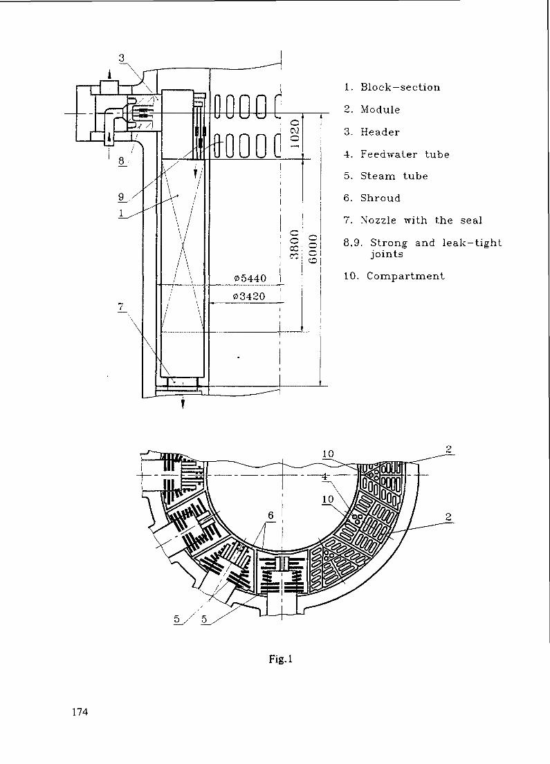
1. Block-section
2. Module
3. Header
4. Feedwater tube
5. Steam tube
6. Shroud
7. Nozzle with the seal
8,9. Strong and leak-tightjoints
10. Compartment
Fig-1
174

for restraint of the lower block-section part from latteral displacements. The seal designassures longitudinal temperature displacement of the block-section.
Strong and leak-tight joints 8 and 9 ensure the connection of steam generator items,made of titanium alloys to the stainless steel items and are located on each feedwatertube 4 and steam tube 5.
The block-section is installed into the reactor vessel and headers 3 are weldedto the vessel from outside.
The steam generator design permits inspection by non-destructive methods duringfabrication, including 100% radiographic inspection of all welded joints subjected toprimary and secondary pressures.
Unification of items and assembly components by block-section, modules and steamgenerating elements, application in steam generator design of a minimum quantity of itemsof standard sizes and assembly of components of different types and dimensions allowsorganization of parallel process flows for automated manufacturing. This assures highquality of a steam generator and reduces the fabrication cycle.
The steam generator operates as follows. Primary coolant from the pressure chamberenters the shrouds of block-section 1, flows downward between steam generating elementstransferring heat to the secondary medium. In the lower part of the shroud the coolantleaves the block-section through the nozzle with a seal 7 and goes further to the coreinlet.
Feedwater enters feed tubes 4, then it enters modules 2 and is distributed betweensteam generating elements. Then water goes upward through the steam generating elementsand is converted to superheated steam. Steam from the modules passes through steamtubes 5 and holes in the block-section headers and is supplied to steam chambers andremoved from the steam generator.
The steam generator design gives the possibility of diagnostic control in operationand during sheduled shut downs of the reactor by the methods adopted in Russia. Itallows estimation of the real state of the steam generator and to ensure its operationalsafety.
The steam generator design is maintainable and allows to leakage wear in and toisolate any non-leaktight module hi case of intercircuit leakage. If one module is isolated,the heat exchange surface is reduced by 1/216 part.
The modular structure of the steam generator allows performance of complexrepresentative testing of steam generator including the confirmation of lifetimecharacteristics in the rigs of relatively low power.
In the steam generator project design decisions are realized which have resultedin limitations of cross-sections, through which primary coolant leaks in case of somestructural failures, including the rupture of a feed tube sheet or of the nozzle in thevessel.
Examination of various SG element failures has shown that the maximum equivalentdiameter of the leak is between 5-40 mm.
5. STRUCTURAL MATERIALS
The following principal requirements were taken into account during choice ofstructural materials for a cassette type straight-tube steam generator:
1) sufficient level of mechanical properties at operating temperatures taking accountof long term operation;
2) corrosion resistance in primary and secondary working media;
175
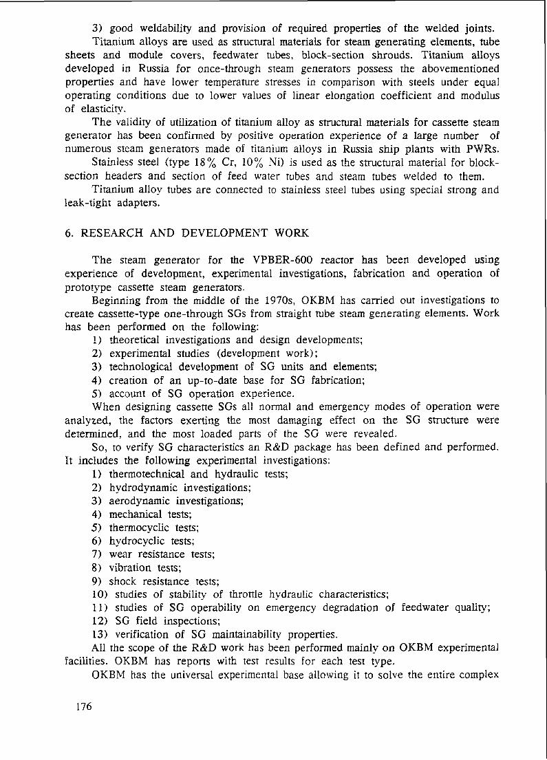
3) good weldability and provision of required properties of the welded joints.Titanium alloys are used as structural materials for steam generating elements, tube
sheets and module covers, feedwater tubes, block-section shrouds. Titanium alloysdeveloped in Russia for once-through steam generators possess the abovementionedproperties and have lower temperature stresses in comparison with steels under equaloperating conditions due to lower values of linear elongation coefficient and modulusof elasticity.
The validity of utilization of titanium alloy as structural materials for cassette steamgenerator has been confirmed by positive operation experience of a large number ofnumerous steam generators made of titanium alloys in Russia ship plants with PWRs.
Stainless steel (type 18% Cr, 10% Ni) is used as the structural material for block-section headers and section of feed water tubes and steam tubes welded to them.
Titanium alloy tubes are connected to stainless steel tubes using special strong andleak-tight adapters.
6. RESEARCH AND DEVELOPMENT WORK
The steam generator for the VPBER-600 reactor has been developed usingexperience of development, experimental investigations, fabrication and operation ofprototype cassette steam generators.
Beginning from the middle of the 1970s, OKBM has carried out investigations tocreate cassette-type one-through SGs from straight tube steam generating elements. Workhas been performed on the following:
1) theoretical investigations and design developments;2) experimental studies (development work);3) technological development of SG units and elements;4) creation of an up-to-date base for SG fabrication;5) account of SG operation experience.When designing cassette SGs all normal and emergency modes of operation were
analyzed, the factors exerting the most damaging effect on the SG structure weredetermined, and the most loaded parts of the SG were revealed.
So, to verify SG characteristics an R&D package has been defined and performed.It includes the following experimental investigations:
1) thermotechnical and hydraulic tests;2) hydrodynamic investigations;3) aerodynamic investigations;4) mechanical tests;5) thermocyclic tests;6) hydrocyclic tests;7) wear resistance tests;8) vibration tests;9) shock resistance tests;10) studies of stability of throttle hydraulic characteristics;11) studies of SG operability on emergency degradation of feedwater quality;12) SG field inspections;13) verification of SG maintainability properties.All the scope of the R&D work has been performed mainly on OKBM experimental
facilities. OKBM has reports with test results for each test type.OKBM has the universal experimental base allowing it to solve the entire complex
176
of tasks arising when designing SGs. It is evident that each specific SG design shouldbe subjected to acceptance tests aiming at demonstration of the SG characteristics to theCustomer. The OKBM experimental base includes test facilities of various powers includingthose of 45 MW.
Mass production of the cassette-type SGs is established in Russian enterprises whichhave modern technological equipment including automated complexes.
7. OPERATION EXPERIENCE OF CASSETTE STEAM GENERATORS
Now, cassette SGs are operated as a part of transport VVER reactor plants.More than 212000 straight-tube steam generating elements operate as part of
cassette SGs.Total operating experience of all active steam generators is more that 500000 hours.
Simulating a standard operation model in the laboratory verified lifetime of more than100000 hours.
Cassette SGs have never failed during operation.
8. CONCLUSION
Positive experience of theoretical and experimental investigations, accumulated inOKBM, the results of cassette steam generator operations in operating PWRs, wide layoutpotentialities of cassette steam generators in combination with high specific characteristics(compactness and specific power) allowed development of integral type reactor plants,of various powers (including 600 MW electric power) and purposes.
177

LOCA FEATURES PECULIAR TO AN XA974598INTEGRAL WATER COOLED PWR
Ya.K. KOZMENKOV, Yu.I. OREKHOVInstitute of Physics and Power Engineering,Obninsk, Kuluga Region,Russian Federation
Abstract
LOCA initiated by a guillotine break of the pressurizer surge line has beenconsidered in the paper. The failure of two emergency core cooling system (ECCS)trains was also postulated, that turns the considered accident sequence into abeyond the design basis (BDB) class. Basic design characteristics of the ABV reactorand the containment system are presented as well as the factors of much importanceto the accident progression.
SCDAP/RELAP5/MOD3.1 was used as the computer code for the simulationof reactor and containment system behavior in the course of the accident. Since anoncondensable driven pressurizing system was employed in the reactor design, thepresence of dissolved nitrogen in the primary water was taken into account incalculations.
The important feature of the simulated accident is the primary system refillingwith the water of pressure suppression pool driven by the pressure differencebetween containment system compartments.
Main Design Characteristics of Reactor Plant and Containment System
A beyond the design basis loss-of-coolant accident (LOCA) for the floatingnuclear power plant (FNPP) with two water-cooled integral ABV reactors (Fig. 1)has been considered. Primary coolant natural circulation is ensured in the ABVreactor. The multi-sectional once-through steam generator is built inside the reactorpressure vessel. A noncondensible driven pressurizer is connected to the reactor by apipeline. The design characteristics of the ABV reactor plant are presented inTable 1.
The emergency core cooling system of the FNPP includes two active (highand low pressure) subsystems designed to make up the primary coolant losses evenat the guillotine break of any primary pipeline. Besides the ECCS, the activeresidual heat removal (RHR) system with emergency feedwater pumps (EFP) or thepassive RHR system with pressurized accumulators can be used to provideemergency heat removal through the steam generator.
All primary system pipelines, including the pressurizer surge line, have 15 mmdia. orifices to reduce the leak flow rate during a LOCA.
The FNPP accident localization system includes the following leak-tightcompartments (Fig. 2):
• Reactor containment shell,• Pressure suppression pool (PSP) compartment.• Auxiliary equipment compartment (not shown on Fig. 2).
179
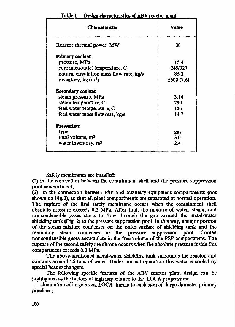
Table 1 Design characteristics of ABV reactor plant
Characteristic Value
Reactor thermal power, MW
Primary coolantpressure, MPacore inlet/outlet temperature, Cnatural circulation mass flow rate, kg/sinventory, kg (m3)
Secondary coolantsteam pressure, MPasteam temperature, Cfeed water temperature, Cfeed water mass flow rate, kg/s
Pressurizertypetotal volume, m3
water inventory, m3
38
15.4245/327
85.35500 (7.6)
3.1429010614.7
gas3.02.4
Safety membranes are installed:(1) in the connection between the containment shell and the pressure suppressionpool compartment,(2) in the connection between PSP and auxiliary equipment compartments (notshown on Fig.2), so that all plant compartments are separated at normal operation.The rupture of the first safety membrane occurs when the containment shellabsolute pressure exceeds 0.2 MPa. After that, the mixture of water, steam, andnoncondensible gases starts to flow through the gap around the metal-watershielding tank (Fig. 2) to the pressure suppression pool. In this way, a major portionof the steam mixture condenses on the outer surface of shielding tank and theremaining steam condenses in the pressure suppression pool. Coolednoncondensible gases accumulate in the free volume of the PSP compartment. Therupture of the second safety membrane occurs when the absolute pressure inside thiscompartment exceeds 0.3 MPa.
The above-mentioned metal-water shielding tank surrounds the reactor andcontains around 26 tons of water. Under normal operation this water is cooled byspecial heat exchangers.
The following specific features of the ABV reactor plant design can behighlighted as the factors of high importance to the LOCA progression:- elimination of large break LOCA thanks to exclusion of large-diameter primary
pipelines;
180

Control rod drivemechanism
Closure head assembly
Reactor pressure vessel
Steam generator modules
Reactor Core
Fig. 1 ABV REACTOR
181

REACTOR CONTAINMENTSHELL
<--o
•B
I
PSP COMPARTMENT
SUPPRESSION POOL
=o;Fig. 2 System of accident localization
182

The main design characteristics of these compartments are presented in Table 2.
Table 2 Containment system design characteristics
Plant premises
Parameter
Initial free volume, m3
Water inventory, m3
Total heat exchange surface ofcompartment walls and equipment, m2
Heat exchange surface of the wallscooled with external air, m2
Total mass of compartment wallsand equipment, kgMaximum permissible pressure incompartments, MPa
Containmentshefl
172-
228
128
35600
0.6
PSPcompartment
4025
85
38
13300
0.6
Auxiliaryequipment
compartment
70-
22
22
20600
0.6
- employment of the outflow restrictors to decrease the primary coolant lossduring a LOCA;
- upper location of the penetrations of the primary pipelines through the reactorpressure vessel;
- large water inventory above the core;- favourable conditions for the emergency heat removal through the steam
generator thanks to the primary system integral design;- nitrogen presence in the primary system, including nitrogen dissolved in the
primary coolant during reactor plant operation in transient regimes. The analysis ofthis factor is one of the main objectives of the study.
Accident Scenario
The postulated LOCA scenario is based on the following assumptions andevents:
1. The accident is initiated by the double-ended break of the pressurizer surgeline near the reactor pressure vessel.
2. Both trains of the ECCS fail to operate.3. Additional failure of the shielding tank cooling system is supposed.
183

4. Full power operation of the reactor plant is assumed before the start of theaccident.
5. Reactor scram occurs when the reactor pressure reduces to 12.5 MPa.6. The EFP starts to operate after reactor shutdown and provides around 15 m3/h
of feedwater at a temperature of 40 C.7. The total amount of nitrogen dissolved in the primary water inside the reactor
vessel is assumed to be 9.4 kg. The assessment of initial nitrogen concentration hithe reactor coolant was based on the Henry law.
8. No operator action is performed to mitigate the accident.
Simulation Results
The SCDAP/RBLAP5/MOD3.1 computer code was used to determine boththe reactor and containment system behavior in the course of the accident. Severalmodules of the code were modified for this study to simulate the process of dissolvednitrogen release from the primary water to the vapor phase within the reactor vessel.
The computer simulation results showed that the reactor coolant leak ratethrough the pipe break decreases rapidly during the initial 30 seconds of theaccident. Its value reduces from 16.5 kg per s at the accident beginning to about 3kg per s, when the reactor end of the pressurizer surge line becomes uncovered andthe leak flow changes from liquid to vapour. The subsequent discharge rate of steamfollows the primary pressure (Fig. 3).
£•fQ.OE+0
1.5E+6
1.0E+6
5.0E+5
O.OE+0
100 200 300 400 500
2000 4000 6000 8000 10000 12000 14000 16000 18000TIME,*
Fig. 3 Reactor pressure change during the accident
184

The heat removal from the primary system through the steam generator hasan essential influence on the reactor coolant discharge rate and the rate of reactorpressure reduction. Heat transferred to the steam generator secondary exceeds theenergy transferred to the coolant from the core for almost the whole duration of theaccident, causing a decrease in the primary system pressure and temperature.However, the process of nitrogen release from the primary water (Fig. 4) leads to areduction in the steam condensation rate at the primary side of the uncovered steamgenerator tubes. The break flow reduces at a lower rate as the result of this process.A significant part (about 20 %) of the released nitrogen mass remains in the vaporphase inside the reactor pressure vessel and localizes mostly above the water levelinside the steam generator.
The containment shell pressure continues to rise even after the first safetymembrane rupture at 16 s and reaches its maximum value just before the secondmembrane ruptures at approximately 2650 s (Fig. 5). The values of containmentatmosphere pressure and temperature do not exceed permissible design limits of 0.6MPa and 150 C during the accident progression. Their maximum simulated valuesare 0.34 MPa and 130 C, respectively.
A steady pressure decrease in all containment system compartments begins at-5000 s of the accident. At the same time, a positive pressure difference between thecontainment shell and the PSP compartment starts to reduce to zero and becomesnegative at -7000 s. This result is explained by decreasing discharge rate of theprimary coolant and continuing heat removal from the containment atmosphere tothe containment vessel walls and interior equipment, including the metal-watershielding tank.
0.01500
Fig. 4 1. Nitrogen content in coolant inside reactor vessel(O - primary coolant liquid phase, D - primary coolant vapor phase)
2. Nitrogen discharged from reactor vessel ( A )
185

3.5E+5
COCOUlOL0.
1.5E+5
1.0E+6
\_
__,—— —-^————,____——,—— ——,
0 2000 4000 6000 8000 10000 12000 14000 16000 18000
HME,»
Fig. 5 Pressure inside containment shell (—— )and PSP compartment ( - - - - )
During the next phase of the accident, a gradual displacement of water fromthe PSP compartment to the containment shell is observed as the result of increasingpressure difference between these compartments. At -10000 s, the rising water levelinside the containment shell covers the pressurizer surge line break located at theelevation of ~3.5 m above the shielding tank bottom level. After this event, thereactor begins to refill with suppression pool water (Fig. 6). The mass of coolantinside the reactor pressure vessel increases up to the value of-6000 kg and stabilizesbeginning at -13000 s. During the last 5000 s of the transient, the calculated leakflow rate has a small value. The direction of the flow alters irregularly, so that thecoolant mass within the reactor remains almost invariable for the rest of theaccident simulation.
1500
1000
500
-500
2000 4000 6000 8000 10000 12000 14000 16000 18000TIME,*
Fig. 6 Total loss of reactor coolant
186

The results of the accident simulation indicate that a sufficient inventory ofthe primary coolant remains within reactor vessel to maintain reliable core cooling.The critical heat flux is not reached in the core during the accident progression.
The further state of the reactor plant will depend on assumptions concerningthe degree of leak-tightness of the containment system compartments, RHR systemworking conditions, and operating staff efforts to activate failed safety systems. Theavailable grace period is long enough to undertake measures for accident control.
Conclusions
In the course of performing the simulations, it was found that:
1. Neither core uncovering nor the critical heat flux in the core was reachedwithout any operator action during the accident progression.
2. The process of nitrogen release from liquid to vapour phase within the reactorpressure vessel led to increased total loss of the primary coolant, but the values ofcontainment shell atmosphere pressure and temperature did not exceed theirpermissible design limits.
3. Reactor refilling with the water of pressure suppression pool driven by thepressure difference between containment system compartments occurred during thelast phase of the accident.
187

STUDY OF THE KINETICS OF THE XA9745986STEAM-ZIRCONIUM REACTION USINGA ONE ROD ASSEMBLY MODEL
S.G. KALIAKIN, Yu.P. DZHUSOV,R.V. SHUMSKY, Yu. STEINInstitute of Physics and Power Engineering,Obninsk, Kuluga Region,Russian Federation
Abstract
The results of the investigation of steatn-zirconium reaction kinetics at tiie HPE
simulator surface are presented in the paper. The dynamic characteristics of the hydrogenproduction resulted from the footed surface dnout are determined.
INTRODUCTION
The necessity of the knowledge of the laws of hydrogen generation during the
interaction between the HPE shells made of the zirconium alloy and water coolant ishighly increased when the problem of severe out-of-project accident was initiated, so
their evolution is determined by the hidrogen discharge.In fl] on the base of publications available the analisis was made of the hidrogen
generation processes under severe accidents resulted from the circulation break off.
From the estimations presented there regarding the amount of generated hydrogenduring some first hours after the accident, it follows that the general source of the
hydrogen is the reaction of zirconium with steam-water mixture. For example, thevelocity of hydrogen generation may reach the value of 726 kg/h for the ordinerycommercial APP USA.
Among the latter publications dealing with this problem the paper of the Japanauthors [2] is remarcable. In this paper the results of the in-pile experiments arepresented devoted to the study of hydrogen generation during the steam-zirconiumreaction when the accidant situation was initiated by reactivity. The HPE was cooledby subsaturated water in the film boiling regime. The amount of the hydrogengenerated was determined by the void fraction gauge at the channel exit and from themetallografic examinations also. In spite of the significant discrepancy between theresults obtained by these two methods, the data allow to make conclusions about thestrong temperature influence upon the hydrogen production.
189

~ uFig. 1. Scheme of the Facility for Steam-Zirconium Reaction
Investigation.1 - Heating Element (HPE Simulator); 2 - Transparent Body; 3 - Bars; 4 -<PjiaHeq; 5 -Thermocouples; 6 - Refrigerator; 7-Hydrogen Accumulator; 8 - Level
Gauge SAPPHIRE-22DD Type; 9 - Replacing Tank; JO - Water Feed Tank.
190

The aims of the present paper are as follows: experimental study of the hydrogengeneration process as a result of the HPE zirconium shell oxigation in steam-wateratmosphere under- conditions of assembly dryout due to the circulation failure; using ofthe data obtained when developing the corresponding codes.
Presented in the paper are the results of first experiments having, in general,methodological purposes. At the one-rod assembly model the peculiarities of thehydrodynamic processes of its dry-out was visualised and the reliable method ofhydrogen production measurement was veryfied.
EXPERIMENTAL FACILITY
The experimental facility is presented schematically in Fig. 1. Its basic elementaare the next:• heating element: spiral or with internal heater /;• assembly body made from the transparent quartz-glass tube for assembly dre-out
process visualization 2;• bars 3;• flange 4;• thermocouples J;• refrigerator 6;• calibrated measuring glass for hydrogen accumulation 7;• level gauge (volume) in 8:• expansion tank for collection of water replaced by steam and hydrogen 9;• water-provided tank 10.
The collection and treatment of the information is fullfilled by the computer-controlled system.
During the process of the model dry-out a steam-water mixture is directed to therefrigerator where it is condenced, while hydrogen is led to the accumulator. Hydrogenreplaces water to the calibrated replacing tank. The pressure difference gauge registersthe change of water level in replacing tank vs. time what enables to identify the momentof the steam-zirconium reacton beginning and to measure the amount og the hydrogenproduced. The thermocouples are used for measuring the temperatures of the simulatorsurface and that of steam. For the simulator to be vacuumed and and after that filled
with argon serves a special system.
191

EXPERIMENTS
In the experiments carried out two types of heater were used: one of spiral type
and another as a rod with internal heating.The spiral type heater was fabricated of stainless steel capillary tube 4 ram in
diameter. Inside this heater a small 60 x 5 mm plate zirconium was arranged. Thechromel-alumel thermocouple was aranged at the plate centre.
The rod (HPE simulator) was made of the zirconium tube 09.3 x 0.5 mm. It washeated by molybdenum-made electric heater arranged inside which was insulated fromthe rod wall by pressed magnesium oxide. The total length of the simulator was 550mm and that of the heated zone was 300 mm. The AC voltage was supplied to thesimulator shell ahd heater from the transfomer. The internal part of the simulator wasfilled with argon.
The technique of the experiments carrying out was as follows. After the facilitybeing filled with distilled deairated water one turned on simultaneously the simulator
heating and the system recording in time the temperatures of the simulator surfase andexitingd steam and water level in accumulation tank. Once the electric power wasturned on, the simulator surface reached the saturation temperature and the boiling tookplace. The beginning of boiling was accompanied by intensive dry-out of the model andconsecutive increasing of the rod surface temperature. The front of temperatureincrease was spread down the rod following the water level in assembly. Theexperiment was finished when the volume gauge signal reached its extreme value.
RESULTS OF THE EXPERIMENTS
The experiments have shown that the noticeable hydrogen production due to thesteam-zirconium reaction took place at the temperature about 650 °C. It was observed
both visually as hydrogen bubbles in the accumulator and by record of the water level
changes in the tank 9. In the teats with spiral heater where the temperature didn'texceed 800 °C, it was marked also that the amount of hydrogen produced diminished
with every consecutive turning on of the heater. It apparently may be explained by the
192

v,CM3
300
250
200
150
100
50
0
i i i i i i
- —
T T
VV
-
1 1 1 1 ! 1
/;°c1200
1000
800
600
400
200
00 50 100 150 200 250 300 350
t, ceacFig. 2. Change of the water volume in accumulator tank
and simulator surface temperature vs. time.—————— - Test N.I: -__- - Test N. 2.
influence of the zirconium oxide layer at the rod surface on the steam access to the cleanziconium surface and, finally on the hydrogen production. At the test with the rodsimulator, however, at the temperature of 1000 °C there was a local break-off in oxide
film. It may be resulted from both by the rod distorsion and by the hydrodynamic
exerting of the steam-droplet mixture on its surface.In Fig. 2 the results of two tests camed out at the identical initial conditions with
the rod IIPE simulator are shown. The electric power in both tests was 1.5 kW. Fig.2illustrates evidently the dynamics of the assembly dryout and the hydrogen discharge
during steam-zirconium reaction. The curves V(i) and T(l) are con-elated with each
other qwite well. So, the signal from the level gauge being initially constant begins to
increase with the beginning of the steam-zirconium reaction. It's the moment when therod temperature reaches its maximum value. At the meam temperature of 1000 °C the
amount of the hydrogen produced during 170 s was as much as 143 cm3 in the test No. 1and 110 cm-1 in the test No.2. The considerable rod deformation over the length was
marked.
193

In [3] the measuring of the amount of hydrogen produced .in the steam-zirconiumreaction was carried out at the temperature of 1000 °C. The measuring technique wasin determination the mass increase of small zirconium specimens in steam atmosphereduring the definite time and consecutive calculation the amount of hydrogen. The mean
value of the hydrogen volume produced by 1 cm3 of the specimen surface per 1 s wasabout 0.0136 cm3. In our tests this value was as much as 0.0125 cm3. The agreement is
quite satisfactory. It may be consider as a confirmation of the reliability of thedilatometric method used for the measuring the amount of hydrogen produced.
CONCLUSONS
Experimentally it has been shown that the dilatometric method of the amount ofhydrogen produced during steam-zirconium reaction is a perspective one for careful!
investigation of this reaction kynetics.The visualization of the process of the one-rod assembly dry-out has been carried
out.
REFERENCES
1. KLovalevitch O. M., Budaev M. A. The Problem of Hydrogen Production at APPAccidents. Atomtiaja technikaza rubezhom, 1952, N. 12, c. 25.
2. Fujishiro, T. Hydrogen Generation during Cladding/Coolant Interactions underReactivity Initiated Accident Conditions. Report Presented at the International
Conference NURETH-4, Karlsruhe, 1992. p. 23.
3. Levin A.Ya., Izrailevsky L. B., Morozov A. M. Investigation of Interaction ofZirconium with Steam at 1000 °C. Thermohydraulic Processes on APP Facilities,
Proceedings of VTI, Moscow, Energoatomizdat, 1986.
194

LOSS OF COOLANT EXPERIMENTS FOR THE XA9745987TEST NUCLEAR HEATING REACTOR
MA CHANGWEN, BO JINHAI,JA HAIJUN, GAO ZUYINGInstitute of Nuclear Energy and Technology,Tsinghua University,Beijing, China
Abstract
A Series of tests has been done for the three cases( breaking pipe opened in the gas plenum, near the liquid level and
submerged in the water) in the Test Heating Reactor.Experiments show that the three cases of LOCA ( Loss of Coolant
Accident) have different patterns. In the case of a breaking pipeconnected into the gas plenum the quantity of lost water is independentof the diameter of the breaking pipe. In the case of a breaking pipelocated near the liquid level, the quantity of lost water depends on thelocation of the pipe. In the case of breaking pipe submerged in thewater, all water above the break will be discharged.
The patterns of the discharge for the three cases are given in thepaper.
Key words: Loss of coolant; Nuclear heat reactor
1. Introduction
District heating reactors must be built near the heating load ( heatgrid ) . That means they must be built near cities. So the safetyrequirements for DHR are very strict.
For integral reactors protection against loss of coolant is one of themost important considerations.
On the pressure vessel of a integral reactor, there is no penetrationpipe with big size, LOCA is possible only through pipes with smallsizes. The possible ways of LOCA are as follows:
© Water discharge through the safety valve.CD Water discharge caused by a pipe breaking ( The pipe is
opening in the steam plenum ) .
195

(D Water discharge caused by a breaking pipe (the pipe is openingunder the water level.
For checking the design safety of the 5MW Test Heating Reactor( NHR-5 ) and investigating the characteristics of LOCA during
the discharging process, a series of tests have been done on themodel thermohydraulic loop in INET.
The test model loop was built on the base of similarity theory for theNHR-5.
The loop consisted of two circuits. The first circuit included twoheating test sections (to model fuel assemblies ) , a rising pipe (tomodel the chimney) , steam-water separator, steam condenser, cooler,down pipe, valves ( to model resistances ) and measurementapparatus.
The Condenser and cooler are cooled by the water of thesecondary circuit. Secondary circuit water transfer heat to theenvironmental air by an aircooler.
In order to study the effects of drain position on the drain process,three positions of the drain orifices have been selected. The first drainorifice is located at the top of the loop. It is used to model thecase of " safety valve opened and can't be reset" . The secondorifice is located in the steam plenum of the separator. It is used tomodel the case of a breaking pipe opened in the steam plenum.In the NHR-5, most pipes penetrating the pressure vessel areconnected to the steam plenum. The third drain orifice is located underthe water level. It is a pipe, opening under the water level at about 3m.It is used to model the case of a boron-injection pipe breaking.
The diameter of the heating rods, heating length, height of thechimney, resistance coefficient at the inlet of the heating section, totalresistance of the loop, density of the heating power and parametersare the same as those in the 5MW Test Heating Reactor, in order tokeep the geometric and hydraulic similarity conditions.
In the water discharge test through the safety valve, according tothe geometric similarity, the diameter of the drain orifice should beselected at 4. 3mm. To study the relationship between the orifice
196

condenser
preheater
rig.l. Schematic ciiasram of the test IOOD
diameter and quantity of drain water, besides 4.3, orifice diameters 6.0and 8.5 m m are also selected in the tests.
During the test, the pressure of the steam plenum, watertemperatures at the inlet and outlet of the heating section, drainwater flow rate, and surface temperature of the heating elementsare measured. Pressure and pressure defferences are measuredthrough transducer type 1151. Drain water quantity is measured byweighting the condensate and measuring the water level.
2. Discharge test through the safety valveAfter opening the safety valve and cutting the heating, the pressure
of the test loop decreased fast. Part of water vaporized. The drain ratedecreased with decreasing of the pressure, until the loop pressure wasbalanced with the back pressure (drain stoped) .
A typical test curve of the pressure decreasing with time is shown inFig.2, as well as a curve calculated according to gas critical flowmethod. The two curves fit well enough. It means that the drain
197

Fig.2 Pressure change in the upper plenum
-- 5
oniice diam«er(imn):1 S.52 6.03 -J.3
Fig.3 Effect of the orifice diamerer on the pressurein the upper plenum
through the safety valve essentially is a gas critical flow. It is easy tounderstand, because during the drain process, the ratio of backpressure to the loop pressure most of the time is lower than thecritical pressure ratio. In the drain test through the safety valve thedischarge orifice is located at the top of the loop. So almost is onlyvaporized steam is discharged.
That the drain water quantity can be calculated by the critical flowmethod is an important conclusion for the design.
Experiment shows another important fact that is for the sameinitial pressure and temperature the drain water quantity will be thesame, no matter the orifice diameter is big or small. Only the balancetime will be shorter or longer (longer balance time refers to thesmaller orifice diameter) . ( See Fig. 3 ) . This means that, at the
198

initial conditions of the design parameters ( pressure and watertemperature ) , for the Test Nuclear Heating Reactor, during theprocess of drain through the safety valve the total quantity of drainwater is about 18-20 % of initial water inventory, no matter whetherthe safety valve is fully opened or partly closed.
For the Test Nuclear Heating Reactor ( NHR-5 ) to cover thereactor core and to ensure necessary cooling only about 40 % of initialwater inventory is needed. So the NHR-5 is enough safe during aLOCA through the safety valve. That the total quantity of drainedwater no more than 18 - 20 % of initial water inventory is confirmed bythe calculation of heat balance. So it is creditable.
3. Discharge test of a pipe break from the steam plenum
The main difference between discharges through the safety valveand a pipe break from the steam plenum is the position of thedischarge orifice. The pipe from the steam plenum is located lowerthan the safety valve. In normal regimes it opens into the steamvolume. But during the discharge process, it may some times becovered by water or two phase liquid. In this case the total drainquantity of water depends on the opening is covered or not.
Discharge from different heights ( distance to the initial waterlevel) has been tested.
In the case of small heights at the beginning of the dischargeprocess the level of two phase liquid ( cause by the vaporization )may be higher than the discharge orifice. It causes a mixed dischargeof water and steam, and increased the total drain quantity. Speciallyfor the bigger orifice diameter the discharge process is stronger, thetotal drain quantity is increased notable. This can be seen in Fig. 4.For the case of mixed discharge, the total drain quantity may beincreased from 19 % to 25 % of initial inventory ( orifice diametersare increased from 4. 3mm to 8. 5mm respectively ) . The less theheight difference between the initial level and discharge orifice, themore the total drain water quantity.
199

Tests showed that when the water inventory increased from 71% to84% of total volume the total drain water quantity increased from 17.1% to 20.3% of the total water inventory.
4. Discharge test of breaking pipe from the water volume
In the NHR-5 some pipes are connected under the water level, suchas the boron injection system pipe, the pipe for the hydraulic drivingfacility for control rods etc. A pipe break of this type is moredangerous. In the case all the water above the inlet of the pipe will bedischarged as well as some water lower than the inlet because ofsiphonage.
A discharge test has been made to model a pipe breaking inthe boron injection system. The boron injection pipe is opened underwater at a level equivalent to the middle of the chimney.
In the test steam content, drain water quantity, liquid level, pressureand their transient characters have been measured.
The typical pressure change during the test is shown in Fig. 5. Thechange of drain water quantity is shown in Fig. 6.
From these figures it can be seen that at the beginning of the drainprocess discreasing of the pressure wasn't very fast, but increasing ofthe drain water quantity was quite considerable. This can beunderstood, because at the beginning water was discharged,vaporized steam compensated for the change of water volume, sothe pressure changed slowly. When the liquid level was lower than ttieopening of the discharge pipe, steam and gas began to drain. Thepressure decreased faster, but the drain water quantity changedreasonably slowly. The decrease of the liquid level from linear changedto slower. Eventually draining stopped because of losing heat andpressure.
When the liquid level was lower than the opening of the pipe, somewater was drained because of siphonage. The greater the distancebetween the pipe opening and the liquid level, the less the drain waterquantity. Consequently there was a smaller the decrease of the level.
200

) - !
Fig.4 Effect of the orifice diameter on the
eac.
2u'
fia.
1614
12
108
64
2
\
?is.5. Pressure change during the discharging process
so
>.
s
620600580560
540
520
500
-180
-160
440
/ !
Fig.6. Change of the discharged water quantity with the time
201
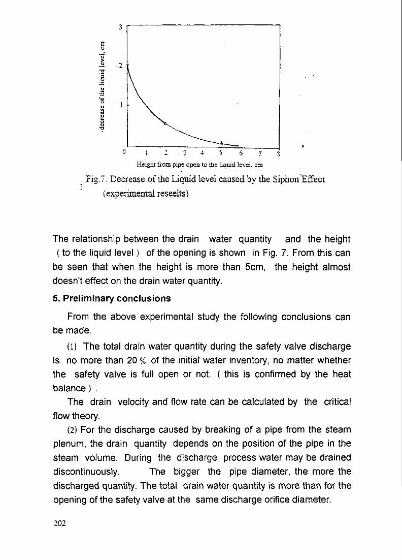
u
J£ .2•T3
oau
0 1 2 . 3 4 5 6 7 3Height from pipe open to the liquid level, cni
Fig. 7. Decrease of the Liquid level caused by the Siphon Effect(experimental reseelts)
The relationship between the drain water quantity and the height(to the liquid level) of the opening is shown in Fig. 7. From this can
be seen that when the height is more than 5cm, the height almostdoesn't effect on the drain water quantity.
5. Preliminary conclusions
From the above experimental study the following conclusions canbe made.
(1) The total drain water quantity during the safety valve dischargeis no more than 20 % of the initial water inventory, no matter whetherthe safety valve is full open or not. ( this is confirmed by the heatbalance) .
The drain velocity and flow rate can be calculated by the criticalflow theory.
(2) For the discharge caused by breaking of a pipe from the steamplenum, the drain quantity depends on the position of the pipe in thesteam volume. During the discharge process water may be draineddiscontinuously. The bigger the pipe diameter, the more thedischarged quantity. The total drain water quantity is more than for theopening of the safety valve at the same discharge orifice diameter.
202

(3) For the discharge from the water volume, the drain quantity ismore than that of a drain from the steam volume. All water above thepipe opening will be drained. When the level is lower than the openingof the pipe, the drain quantity depends on the height differencebetween the liquid level and the opening of the pipe. In a certain rangethe bigger the height difference, the smaller the drain quantity. Underthe conditions of our tests, when the height difference is more than5cm, its effect on the quantity can be negligible.
References
1. Ma Changwen, Bo Jinhai, Za Meisheng and Others:" Safety experimental study for the Nuclear Heating Reactor" ,
INET Report, 1991,2.2. Ja HaijunSafety experimental study on the Boron injection system of the
5MW Heating Reactor, doctoral thesis. 1991, INET, Tsinghua Univ.
203

OPERATIONAL, MANUFACTURING ANDDECOMMISSIONING ASPECTS

CAREM: OPERATIONAL ASPECTS, MAJOR XA9745988COMPONENTS AND MAINTAINABILITY
J.P. ORDONEZ,INVAP S.E.,San Carlos de Bariloche,Argentina
Abstract
The paper presents the design related aspects of operation and maintenance of theCAREM reactor and the principal features of its main components.The paper covers three main topics: operational aspects, major components andmaintainability
Operational aspectsA strong negative thermal coefficient, the use of burnable poisons to compensateburnup and no use of soluble boron for reactivity control characterized reactor control.
Hydraulically driven control rod drives are fully contained in the pressure vessel.The following research and development activities are being carried on:
A critical facility for testing main core characteristics is in final construction stage.A full scale model of control rod drives is currently under test.A full scale model of one steam generator will be constructed and tested.
Major componentsPressure vessel: The empty pressure vessel weights 100 tons. This fact facilitates bothits manufacturing and transport. Internals and steam generators will be mounted onsite. Being the reactor self-pressurized, no pressurizer is included.
Steam Generators: Twelve once-through steam generators are symmetrically placedinside the pressure vessel. Specific design aspects are discussed in the paper.
Containment: The containment is of pressure suppression type. Second shutdownsystem, pressure relief tank, and equipment and installation for manual reactorrefueling and for handling of RPV internals, are all placed inside the containment.Provisions are also made for accommodating RPV internals during refueling andmaintenance operations.
MaintainabilityLay-out: The balance of plant lay-out is conventional. For nuclear island layout,attention has been paid to the fact that the containment will not be accessible duringreactor operation. This fact imposes special demands on equipment reliability, thatwill assure high plant availability.
In service inspection: it is currently under study. Inspection of pressure vessel weldswill follow standard practices. Inspection of steam generators will be performed byconventional eddy-current techniques adapted to tube geometry. Other in-serviceinspections required by ASME XI, SS-50-SG-O2, and local regulatory authorities, arebeing evaluated, most of them being similar to the standard for non-integratedreactors.
Fuel and waste handling: manual refueling of the reactor implies changing 31 fuelelements (approx. 70 kg each) per year. Spent-fuel-pool capacity covers seven yearsof operation; afterwards, dry spent fuel element storage is considered.
Decommissioning: The CAREM concept does not impose specific conditions on plantdecommissioning.
207

1. INTRODUCTION
CAREM reactor features have been described elsewhere /!/. This paper deals withdetailed engineering aspects of its design, that point to important differences betweenthe CAREM, and conventional non-integrated PWRs.
The main aspects to be discussed are:- Operational aspects, including reactor control and control devices.- Major components engineering: reactor vessel, steam generators and containment
vessel- Maintainability, as related to lay-out, in-service inspection, fuel and waste handling,
and decommissioning.
The R&D status corresponding to each item is mentioned when convenient.
2. OPERATIONAL ASPECTS
2.1 Concept of reactor controlTwo characteristics of CAREM reactor core design will be discussed:- strong negative temperature coefficient- no soluble boron for burnup compensation
The stron negative temperature coefficient enhances the self-controlling features ofthe PWR: the reactor is practically self-controlled and need for control rod movementis minimal. In order to keep a strong negative temperature coefficient during the
k*-**uri»*Motio''> Ircd QU'Je tut* I
OOOOOOOQ6cooooooooc^-.ooooooOocoq^ooooooooooOtOOOOOOOOQOOOooopoooot>oc"OOODOOOOOOo cTo o o o o c ~ 'opoooco"
FE " Fu» ?BP • Burnobl* poison
/I / Chapter 6 of IAEA's TECUOC on "Status of Small and Medium Reactors"In print.
208

whole operational cycle, it is necessary to do without soluble boron for burnupcompensation. Burnup reactivity compensation is obtained with burnable poisons, i.e.gadolinium oxide dispersed in the uranium oxide fuel. Nonetheless, soluble boron isused to compensate cold-hot reactivity difference (the strong negative temperaturecoefficient means that a large difference in reactivity must be compensated betweencold and hot states). Soluble boron is also used as a back-up of the safety shutdownrods: if the protection system of the plant orders to shut reactor down, and safety rodsfail to do so, the reactor is shutdown by boron injection.
The effect the two core design features have on burnup, tend to cancel each other. Astrong negative temperature coefficient means that fuel arrangement is not optimumfrom the reactivity point of view, but this charecteristic is compensated by the factthat power density in the core is lower than normal for PWRs. As a consequence, fueltemperature is lower, and the reactivity at hot state is higher.
2. 2 Control systems and devices
2.2.1 Control and protection system
The plant is controlled by a microprocessor based distributed system with a redundantcommunication network. The critical functions of the system required for the plant tooperate, are also duplicated.
The protection system, also based in microprocessors, uses a minimum ofprogrammable actions. The software is written directly in machine language(assembler), with a strong effort made to keep it extremely simple. Apart from thesesmall pieces of software, the protection system is "hard".
These features are similar to most recent designs of non-integrated PWRs: they arenot a particular characteristic of integrated reactors but a new trend in nuclear powerplant design.
SPDS
Voting units Protedion sysfem
Field units
Sofety sensors
209
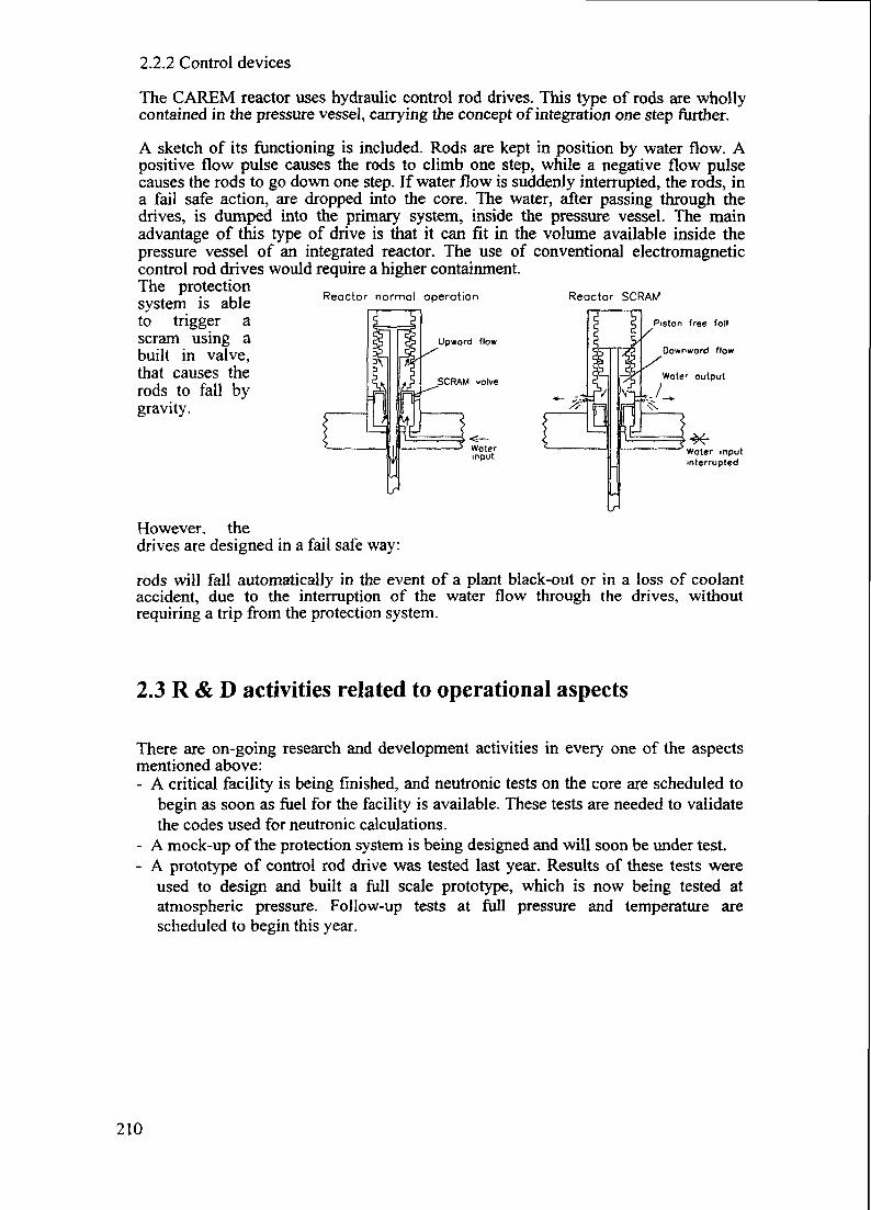
Reactor normal operation
Upward flow
SCRAM valve
Reactor SCRAM
Piston free foil
Downward flow
Water output
2.2.2 Control devices
The CAREM reactor uses hydraulic control rod drives. This type of rods are whollycontained in the pressure vessel, carrying the concept of integration one step further.
A sketch of its functioning is included. Rods are kept in position by water flow. Apositive flow pulse causes the rods to climb one step, while a negative flow pulsecauses the rods to go down one step. If water flow is suddenly interrupted, the rods, ina fail safe action, are dropped into the core. The water, after passing through thedrives, is dumped into the primary system, inside the pressure vessel. The mainadvantage of this type of drive is that it can fit in the volume available inside thepressure vessel of an integrated reactor. The use of conventional electromagneticcontrol rod drives would require a higher containment.The protectionsystem is ableto trigger ascram using abuilt in valve,that causes therods to fall bygravity.
Water inputinterrupted
However, thedrives are designed in a fail safe way:
rods will fall automatically in the event of a plant black-out or in a loss of coolantaccident, due to the interruption of the water flow through the drives, withoutrequiring a trip from the protection system.
2.3 R & D activities related to operational aspects
There are on-going research and development activities in every one of the aspectsmentioned above:- A critical facility is being finished, and neutronic tests on the core are scheduled to
begin as soon as fuel for the facility is available. These tests are needed to validatethe codes used for neutronic calculations.
- A mock-up of the protection system is being designed and will soon be under test.- A prototype of control rod drive was tested last year. Results of these tests were
used to design and built a full scale prototype, which is now being tested atatmospheric pressure. Follow-up tests at full pressure and temperature arescheduled to begin this year.
210

3. MAJOR COMPONENTS
3.1 Pressure vessel
The pressure vessel, without head, steam generators and internal components, weights100 tons.
The internal arrangement of the vessel is dominated by the in-vessel disposition ofsteam generators. Hydraulic control rod drives are also included inside the vessel. Forrefueling, control rod drives must be dismantled. Steam generators can be replacedduring a longer than normal maintenance outage.
The reactor is self pressurized, so no prressurizer is needed. A steam volume, in theupper part of the vessel, accommodatesvolume changes during operation.
The following "in-vessel" variables must be monitored during operation:- Water level- Pressure- Core inlet and outlet temperatures- Neutron flux- Control rod position- Coolant flow
In a natural convection reactor, coolant flow measurement is not straightforward.Different methods are being evaluated; correlation of flow with pressure differencesacross steam generators is the most promising one.
The first four variables can be measured without difficulties specific to this type ofreactor. Control rod drive position is more difficult to measure as a consequence ofdrive design. Ultrasonic methods are being studied for solving this problem.
1 Control drive2 Control drive rod
structure3 Voter level4 Steon generator5 SG water inlet6 SG stean outlet7 Absorbing element8 Fuel element9 Core
10 Core support5 tructure
211

3.2 Steam generators
CAREM uses once through, straight tube steam generators. Twelve steam generatorsare disposed in an annular way inside the pressure vessel, above the core. The primaryside flows through the inside of the tubes, the secondary side flows through theoutside. A shell and two tube plates form the barrier between primary and secondarycircuits.
This type of steam generators has someadvantages:
- Flow of primary and secondary circuits,is countercurrent, which produces ahighly efficient heat exchange.
- Pressure drop in both primary and secondary circuits is low. Pressure drop in theprimary is of fundamental importance in a natural circulation cooled reactor.
- The operation of replacing a steam generator is not a difficult- Steam is superheated, eliminating the need for moisture separators and steam
dryers.- There are no specific problems related to the manufacturing of this type of steam
generators.
However, this type of arrangement poses some problems that must be addressed bydesign:- There is a feedwater inlet and a steam outlet penetration for each steam generator in
the pressure vessel: In CAREM, these penetrations are concentric; in this waytwelve penetrations are avoided.
- Different thermal expansion coefficients between shell and tubes: prestressed tubesare used, to compensate this difference.
- The quality of the water in the secondary circuit must be extremely good: the fullcondensate flow passes through a polisher.
- The in-service inspection of tubes and shell can be quite difficult: This aspect isdiscussed below.
212

TO TURBINEFROM TURBINE
3.3 Containment vessel
The containment is of thepressure suppression type.This type of containment isappropriate for integratedreactors, because reactors ofthis type don't need largecontainment volumes foraccommodating primarycircuit equipment. Theheight and volume of thecontainment are determinedby the requirements posedby refueling operations andnot by the need toaccommodate operatingequipment.
Containment wall acts asheat exchanger forremoving decay heat to theultimate heat sink, which isthe atmosphere: after aLOCA, pressure in thecontainment rises up, till itreaches design pressure,
more than three days after the accident. At this pressure, heat transfer through thecontainment wall to the atmosphere is enough for preventing further pressure
1 CONTAINMENT2 EMERGENCY INJECTION3 PASSIVE COOLING SYSTEM4 WET PREMISE5 PRESSURE SUPRESSION POOL6 SECOND EXTINCTION SYSTEM7 PRESSURE RELIEF TANK8 DRY PREMISE
increases.
No specific manufacturing, transport or erection problems related to this componenthave been identified.
It is not necessary to access the containment during reactor operation: maintenancetasks can be carried out during refueling, as all equipment in the containment is static(no movable parts, apart of a few safety system valves)
3.4 R & D activities related to major components
Research and development activities on major component design are concentrated inthe steam generators. The heat transfer features of the tubes have been tested atCAREM operational conditions in a thermohydraulic loop. A full scale model of onesteam generator is scheduled to be tested next year.
213
4. MAINTAINABILITY
4.1 Lay-out of the reactor and plant
There are no special features related to plant lay-out caused by the integrated designof the reactors. However, some lay-out related features are worth of mentioning:- As the protection system works with a two out of four logic, four independent
instrumentation rooms are placed near the containment. Independently routedcable trays connect these rooms with the main control room and the secondarycontrol room.
- The containment is not accessible during operation, so equipment placed inside thecontainment must be highly reliable, capable of operating continuously for oneyear without maintenance.
4.2 In service inspection of major components
For an integrated reactor, in service inspection is somewhat more complicated than fornon-integrated ones. This problem arises from the fact that integrated reactors havemajor components included in the pressure vessel; hence, it is difficult to access tothese components for inspection. The components included in the pressure vessel alsomake more complicated the inspection of the pressure vessel itself, because they canrender inaccessible some areas of the pressure vessel.
The standards that were studied regarding in service inspection are ASME Code,Section XI and IAEA Safety Series 50-SG-O2. Most of the requirements of thesestandards can be fulfilled, taking in account that most in service inspection activitiescan be carried out during annual reactor refueling.
The problems identified to this date are:- Inspection of welds of the pressure vessel at core level: The plate that separates the
hot leg from the cold leg prevents accessibility to these welds from the inside ofthe vessel. They will be inspected from the outside of the vessel.
- Inspection of longitudinal welds of the shell of steam generators: This weld can beavoided using a complete forge for the shell. If engineering and/or manufacturingreasons call for the use of a rolled plate, there will be only one longitudinal weld,and Osteam generators will be designed so as to have this weld accessible forinspection from the inner part of the pressure vessel.
- Inspection of circunferential welds between steam generator shells and plate tubes:Parts of these welds are inaccessible. A sampling inspection is permitted for thistype of welds.
214

- Inspection of steam generator tubes: The top of straight tubes is readily accessiblewhen the pressure vessel is open, thus no problem with the inspection of tubes isforeseen. To plug a tube, it is necessary to plug both ends of the tube, the lowerend being accessible only through the tube. There are technics developed forplugging tubes in this geometry: it is easier than the sleeving techniques that arecurrently being used. A complete tube rupture could turn repair impossible: in thishighly improbable event, the full steam generator can be replaced, not a verycomplicated operation in a CAREM.
Offices/administrationSecondary Control RoomMain Control RoomCold/hot Dressing RoomSpent Fuel PoolContainmentWaste Treatment PlantHot LaboratoryDecontaminationHot WorkshopVentilation ExtractionReactor Auxiliary SystemsDemineralized Water SystemVentilation Injection
Fuel And Chemical StoreAreaNeutralization PoolAuxiliary boilerChillersChimneyMechanical WorkshopElectrical WorkshopTurbine HallFire And Plant Water TankWater Treatment And Pump
Hall
25 Batteries/Electric BoardRoom
26 Transformers27 Diesel Generators
4.3 Fuel and waste handling
The reactor is refueled annually. Refueling is manual. Half of the core is replaced inevery refueling. Spent fuel is placed in a pool. The pool has capacity foraccommodating the spent fuel produced by seven years of reactor operation. Afterseven years, the older spent fuel elements will be removed to a dry storage.
Waste handling facilities are similar to the ones for conventional PWR. Solid wastemanagement must be tailored to the site and country characteristics.
215

Bridge crone
Floodedwet premiseond RPV
Fuel element[storage pool
4.4 Decommissioning
No specific features related to decommissioning of integrated reactors has beenidentified. Actually, dismantling of the plant will probably be easier than thecorresponding to a conventional PWR: dismantling of the primary system is achievedby just removing the pressure vessel.
5. CONCLUSIONS
The paper gives and overview of the status of CAREM design. The description makesemphasis in those topics that can imply important differences with respect totraditional PWR technologies.
Although some areas in which R&D activities are necessary have been identified, theproblems specific to integrated type reactors are well within the present technologicalcapabilities of the industry.
216

PROBLEMS IN MANUFACTURING AND TRANSPORT OFPRESSURE VESSELS OF INTEGRAL REACTORS
J. KRALOVEC XA9745989Skoda Nuclear Machinery Plzen,Plzen, Czech Republic
Abstract
Integral water-cooled reactors are typical vith eliminatinglarge-diameter primary pipes and placing primary components.i.e.steam generators and pressurizers in reactor vessels. Thisarrangement leads to reactor pressure vessels of largedimensions: diameters. heights and thick valls'and subsequentlyto great weights. Thus, even medium power units have pressurevessels vhich are on the very limit of present manufacturingcapabilities. Principal manufacturing and inspection operationsas well as pertinent equipment are concerned1 welding, cladding,heat treatment. machining. shop-handling. non-destructivetesting, hydraulic pressure tests etc.
The transport of such a large and heavy component makesa problem which effects its design as well as the selection ofthe plant site. Railway, road and ship are possible ways oftransport . each of them having its advantages and limitations.
Specific features and limits of the manufacture andtransport of large pressure vessels are discussed in the paper.
INTRODUCTION
Though the Czech Republic at present time does not intend todevelop and construct integral reactors. a contribution onproblems of manufacturing and transportation of large pressurevessels which is based on the experience from the manufacture ofWER reactors can be inspiring. In addition to that, thesituation in the Czech Republic can be representative to othercountries which could potentially utilize integral reactors. Thesituation is typical with following features:- inland position.- complicated terrain.- geological situation limiting the choice of construction sites.- lack of water transport ways.- complicated network of railways and roads having limitedtransporting profiles as well as limited bearing capacities.
In addition to that, heavy machinery factories which arequalified to produce nuclear components are located out of thedirect reach of water-transport.
Integral water-cooled reactors are typical by the eliminationof large -diameter primary components i.e. steam generators andpressurizers in reactor vessels. This arrangement leads toreactor pressure vessels of large dimensions: dimeters, heightsand thick walls and subsequently to great weights. Thus, evenmedium-size power reactors have pressure vessels vhich are on thelimit of present manufacturing capabilities.
217
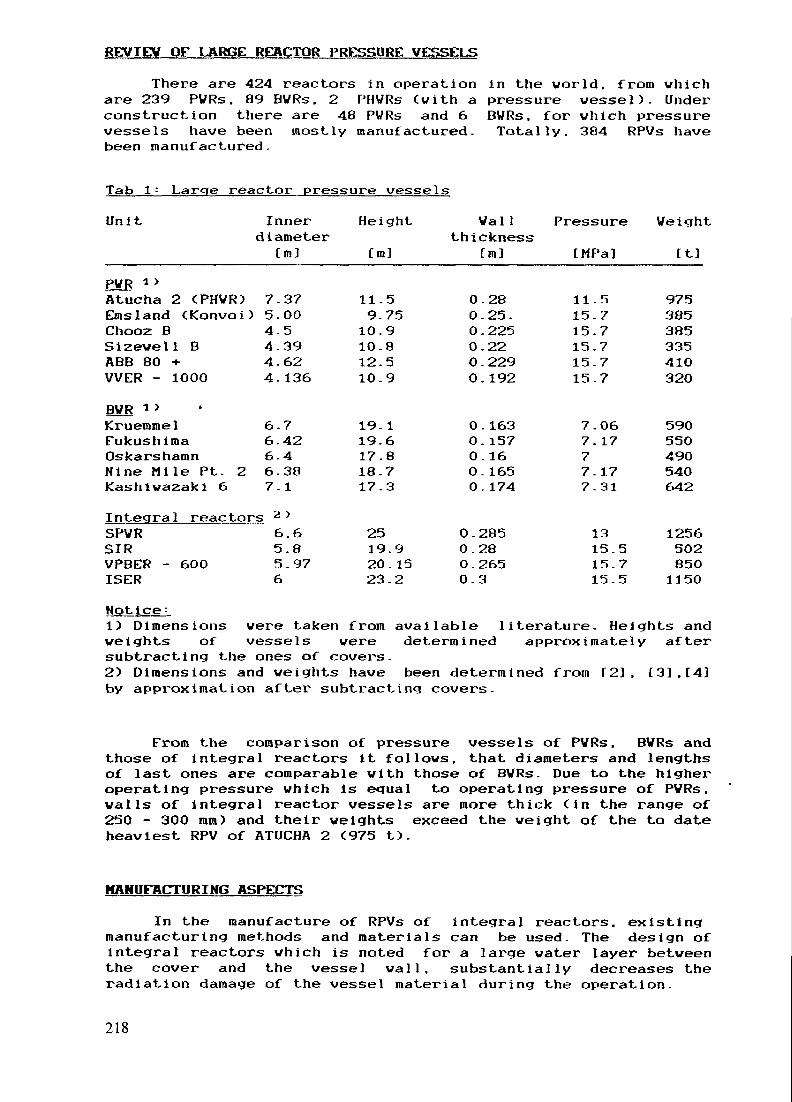
REVIEV OF LARGE REACTOR PRESSURE VESSELS
There are 424 reactors in operation in the world, from whichare 239 PVRs. 89 BVRs. 2 PHVRs (with a pressure vessel). Underconstruction there are 48 PVRs and 6vessels have been mostly manufactured,been manufactured.
BWRs. for which pressureTotally. 384 RPVs have
Tab 1: Large reactor pressure vessels
Unit Inner Height
Cm]
Innerdiameter
[mlVail Pressure Veight
thickness[m] [MPa] It]
PVR * >Atucha 2 CPHVR) 7.37 11.5 0.28Emsland CKonvoi) 5.00 9.75 0.25.Chooz B 4.5 10.9 0.225Sizewell B 4.39 10.8 0.22ABB 80 H- 4.62 12.5 0.229VVER - 1000 4.136 10.9 0.192BVR * >Kruemmel 6.7 19.1 0.163Fukushiraa 6.42 19.6 0.157Oskarshamn 6-4 17.8 0.16Nine Mile Pt- 2 6.38 18.7 0.165Kashiwazaki 6 7.1 17.3 0.174
Integral reactors 2 JSPVR 6.6 25 0.285SIR 5.8 19.9 0.28VPBER - 6OO 5.97 20.15 O.265ISER 6 23.2 0.3
11.515.715.715.715.715.7
7.067.1777. 177.31
1315.515.715.5
975385385335410320
590550490540642
12565028501150
Not ice •-1) Dimensions were taken from available literature. Heights andweights of vessels were determined approximately aftersubtracting the ones of covers.2) Dimensions and weights have been determined from T2]. £3],[4]by approximation after subtracting covers.
From the comparison of pressure vessels of PVRs. BVRs andthose of integral reactors It follows, that diameters and lengthsof last ones are comparable with those of BVRs. Due to the higheroperating pressure which is equal to operating pressure of PVRs.walls of integral reactor vessels are more thick Cin the range of250 - 300 mm) and their weights exceed the weight of the to dateheaviest RPV of ATUCHA 2 C975 t).
MANUFACTURING ASPECTS
In the manufacture of RPVs of integral reactors, existingmanufacturing methods and materials can be used. The design ofintegral reactors which is noted for a large water layer betweenthe cover and the vessel wall. substantially decreases theradiation damage of the vessel material during the operation.
218

Materials
Materials will be used which have proven to be convenientfor PVRs and properties of which are we11-known: weldability.uniformity of chemical composition and mechanical andtechnological properties. even for very thick-waJled componentsand extremely heavy forgings.
Fo11owing materials should be considered:Ni-Mo-Cr type: SA 508 C1.2. 22NiMoCr37. SQV2A.Mn-Mo-Cr type: SA 508 C1.3. 16MKD5. SA 533 Gr.B.Cr-Mo<Ni)type: 15Ch2MFA,15Ch2MNFA.and corresponding Japan steels. eventually improvedmod i f i cat i ons-
The technology of casting extremely large ingots Cup to600t) from these steels have been mastered by leading firmsassuring the required homogenity of chemical composition and highpurlty.
Sem i productsPrincipal semiproducts for pressure vessels are forged rings
and plates. Plates are subsequently hot-stamped to the form ofspherical or elliptical dishes for bottoms and covers.
Rings for Integral RPVs will be about 4m long. 6-7m of outerdiameter and 250 - 300 mm thick. flange-rings will be shorterwith the wall thicknes about 500 mm- There is not such need ofcomplicated thick-walled nozzle rings as at PVR pressure vessel.Plates for dishes w i l l have to have diametres about 10m. It isnot excluded to make the part by welding.
Existing procedures of heat- treatment of forgings forquality Cquenchlng. tempering) give high certainty in reachinghomogenous structure and mechanical properties even in very thickwalls.Velding
Vessels are welded from individual rings and dishes bycircumferential welds. Automated submerged-arc welding toa narrow gap is generally applied. A promissing method could beelectron beam technique which is applicable to large materialthicknesses and allows the performance of high-quality welds inshort time spans.
The simultaneous heating by gas flame or by electricity isapplied during the welding.
The number of circumferential welds in an integral RPV willbe 4-8.
The necessary welding equipment consists of a weldingautomat, rotating positioners of an appropriate loading capacityand of a heating device (electric heaters or gas torch).Monitoring and registration of welding parametres is required.Cladding
Cladding is performed by automated submerged-arc method byusing strip or wire Cmultiple wire) electrodes: plasma techniqueis a pespective method.
219
Follovincj requirements have to be fulfilled when cladding1
ft
- the cladded surface must be clean . without impurities andsulphur inclusions which is assured by piercing ingots by themandrel which removes the central part of the ingot containingsegregates , or by using hollow ingots.- proper laying of individual beads and their mutual overlapping,- an optimized heat input which is important for the depth andproperties of the heat-affected zone under the cladding
All the measures are aimed at eliminating the formation ofunderclad cracks.
The cladding equipment consists of a cladding automat,positioners Crotating ones for cylindrlc surfaces, tilting androtating ones for spherical eliptical and face surfaces) and aheating device.
Stress-relief annealingEach weld and cladding have to undergo the stress relief
annealing by a prescribed procedure= heating-up - dwell- cooling-down, so as to remove residual stresses in the materialwhich attain up to the yield stress of the material.Each sectionwelded from two or more parts must be annealed: it must be keptin view that each annealing impairs material properties.
For the annealing. a furnace must be at disposal whichenables placing in even a whole pressure vessel Dimensions ofintegral RPVs require very deep furnaces (more than 20m). CE.g.the annealing furnace at SKODA Reactor Shop has dimensions7.5x7.5xl5m which makes possible to anneal parts up to 13m long:pressure vessels VVER 440 and VVER 1000 are jl.8 and 10.8 long,respectively) In the last resort. a local annealing can beapplled.
MachiningIndividual semiproducts and sections are machined on large
numeric- and programme controlled machine tools: vertical lathesand horizontal milling and boring machines. The machines have toenable rigid clamping of heavy workpieces and precise control ofthe machining
Main machining operations are as follows-- turning of cylindrical surfaces of rings and welding edges,- turning of spherical and/or eliptical surfaces of bottoms andcovers including welding edges.
- boring holes and cutting threads in vessel flanges for flangebolts.
- boring holes in vessel covers for control-rod-drive nozzles,instrumentation nozzles and flange bolts.
- machining of main nozzles and emergency-cooling nozzlesincluding welding edges.
- machine or manual grinding of outer and inner surfaces ofvessels and covers, etc
220

Inspections and testsA quality assurance programme must be followed during all
phases of the manufacturing process a part of which is aprogramme of inspections and tests.
Main groups of inspections and tests:- material properties Cchemical composition, structure,mechanical properties, transition temperatuure curve etc->- geometry C dimensions, shape, surface quality)- integrity (surface integrity, volumetric integrity,leak-tightness, strength).
Current techniques, apparatusses and devices which have beenused at the manufacture of classic PVR and BVR pressure vesselsare applicable for integral RPVs.
E.g..« radiography of thick welds is performed by linearaccelerators in special shielded cells. A heavy piece istransported to such a cell by a special truck with rotatingpositioners which have to have an appropriate loading capacity.At Skoda, the linear accelerator NEPTUN 1O MeV is used which iscapable to test thicknesses up to 450 mm. A trolley rail-wagonwith rotating positioners of 400 t loading capacity attends thetesting eel 1.
Pressure testThe hydraulic pressure test is an important testing
operation which is required by all relevant codes and standards.The test gives the final confirmation of the integrity andstrength of the pressure vessel. The arrangement of of a largeintegral RPV about 20 m heigh will be similar to one of a BVR RPVhaving similar outer dimensions. The test pressure the value ofwhich is different in individual national codes is in the rangeof 1.1 - 1.6 of the operational pressure, will be comparable withone of PVR RPVs, i.e. 17.3 - 25 MPa.
Check assemblyGood experience has been made at Skoda with application of
the final check assembly of reactor internals. which wasrecommended by the original Russian technical project. Thisoperation consisting in assembly of all reactor internals at themanufacturing shop made possible to find an optimal position ofindividual parts and remove all problems in the shop. Asa result. asseinM ies of reactors and installation if internalsinto pressure vessels on sites vere smooth and fast.
There are more components in integral reactors: in additionto classic internals there are steam-generating elements,water-stream guiding structures etc. A specific feature is a longdistance between control rod drives and the core where controlrods are placed. For such a complex lay-out,the check assembly inthe shop could be a good confirmation of mutual fitting ofindividual components.
221

Shop transportLarge and heavy parts of integral RPVs require appropriate
shop transporting and handling means.Principal handling an transporting operations include-- transport of semiproduts to the shop.- transport of workpieces including the whole RPV between
individual workplaces and machines.- tilting of workpieces from the horizontal position to verticalone and back: finally, the whole pressure vessel have to beerected to the vertical position for the pressure test andback.
- rotating workpieces during fabrication Cwelding. cladding) andinpections (ultrasonic tests, radiography).
- loading workpieces to the annealing furnace, radiographic cellsetc. .
- installation of components during the check assembly.- final expedition of the RPV from the shop Cloading on a truckor ship).
The necessary transporting and handling means are rotatingand/or tilting positioners. trucks. wagons and cranes ofcorresponding loading capacity. Cranes have to have anappropriate lifting travel and - for a precise setting- a. microdrive.
TRANSPORT OF LARGE PRESSURE VESSELS
The transport from the manufacturing plant to theconstruction site is most probably the main limiting aspect ofpressure vessels of integral reactors. Though there were severalpressure vessels the manufacture of which was completed on thesite, the present interest both of plant owners and manufacturersis to have shop-fabricated pressure vessels.
There are three possible ways of transporting such a largeand heavy component: railway, road, ship or a combination of them.
Railway transportAdvantages=- accessibility: both manufacturing plants and construction sitesare usually served by railway.
Disadvantages:- limitations in the diameter (transporting profile) and in theweight.
- a special railway truck is needed
222

Road transportAdvantages:
- accessibility: both manufacturing plants and construction siteshave an access by road.variability^ there is a variety in choosing a most convenientroute of transport.
D i sadvantages =- limitations in diameter (not so strict as at railways: there
is more possibilities in the selection of the route),- a special truck is neededWater transport.Advantages:
- no limitations by dimensions and weight- low priceD i sadvantages =- accessibility: navigable water way is needed both at themanufacturing plant and on the site
Cpmb ined transport^
For the final part of the route, both-. railway and watertransport are combined with the road one for the transport fromthe port or railway station to the reactor building.A combination: railway - ship - road - sship was used at thetransport of the VVER-1000 vessel from Plzen to Belene inBulgaria.
An example of the transport of WER pressure vessels from SkodaA principal requirement laid on the WER reactors which were
manufactured in the Czech Republic under the Russian licence wasthe one of transportability of all components by rail. Therequirement was based on conditions of countries in which theunits were constructed, i.e. the choice of construction sites andtheir availability and localization of manufacturing factoriesout of the reach of water-transport. Skoda Nuclear MachineryPlzeft is one of three plants in which WER reactors were produced(besides Izhora Plant near St.Petersbourgh and ATOMMASH atVolgodonsk, both in Russia). 21 WER-440 reactors and 3WER-1000 were produced at Skoda. A special railway truck KRUPPwas used for the transport of large components including pressurevessels. In several. cases the railway transport was combinedwith road and water one. E.g.. pressure vessels for NPPs Nord inGermany and Zharnowiec in Poland, were transported by rail to theriver port on the Danube near Bratislava and then by the ship tothe Black Sea and around the whole Europe to ports and sites .inGermany and Poland.
223

Tab.2: Sites of VVER - type NPPs and ways of RPVs transport
Site, country Way of the transport
WER-440
4x Paks, Hungary2x Bohunice. Slovakia3x Nord. Germany4x Dukovany4x Mochovce2x Zharnow1ec,Po1and
WER-10OOIx Belene,Bulgaria
2x Temelfn
Railway to Bratislava, river-boat to PaksRaiIwayRailway to Bratislava, ship to GreifswalrJRalIwayRa i1wayRailway to Bratislava, ship to Gdansk
Railway to Jihlava, road-truck to Bratisla-va, river-boat to BeleneRa i1way
CONCLUSIONS
1.Pressure vessels of integral reactor of medium output haveouter dimensions which are comparable with ones of BVRs. Vails ofthem are more thick and their weights exceed to date heaviestRPV.2-No substantial differences are expected between existingmanufacturing technologies of reactor pressure vessels of PVRsand BVRs and one of future integral reactors. Most significantthere will be the size factor. Integral RPVs will be preferrablycompletely manufactured at shops.2- Inspection and test techniques and devices for integral RPVswill correspond to ones currently used at PVR and BVR technology.The shop check assembly of reactor internals should be consideredas convenient preparation for the on-site assembly.
3.The transport of large pressure vessels is the limiting factorof deployment of integral reactors. Integral units of a mediumoutput should be constructed on sites in the reach of watertransport. For the local generation of electricity and heat,small modular units transportable by railway or by road seem tobe more prospective.4.The introduction of integral reactors would require additionalinvestments to productional base. mainly in increasing theloading capacity of manufacturing equipment: welding positioners,supports of machine tools, means of the shop transport etc. Thescope of such Investments will undoubtedly depend on the numberof units required by customers. An appropriate ad-hoc solutionwould be certainly found for the manufacture of small number ofRPVs.
224

ATUCHA 2(PHWR)
EMSLANDKONV01
CHOOZ BNA
290 47368
SIR
190 . S900
oLTk
250 SOOO Ou>
^T225,
FIG.1: PWR PRESURE VESSELS
SPWR
3-
66ft?
jttSOO
VPBER
FIG.2: PRESSURE VESSELS OF INTEGRAL REACTORS
oInoC<
225

REFERENCES
1. World Nuclear Reactors Survey 1994, Nuclear Engineering Int.2. Working Material: The Role of the Agency in Advanced Reactor
System Development. IAEA-TC-792.Vienna. 19923. Working Material-- Review of Advanced WWER Designs.
IAEA-CT0764. Vienna. 19924. Working Materials for the TCM on Integral Reactors. Obninsk,
the Russian Federation. 1994.
226

RADIOLOGICAL ASPECTS OF INTEGRALNUCLEAR REACTOR DECOMMISSIONING
V.S. KUUL. A.V. PICHUGIN, O.B. SAMOILOVOKB Mechanical Engineering,Nizhny Novgorod,Russian Federation
Abstract
World nuclear power rends constantly to decrease the permitted ultimate dose ofNPP personnel and population during normal operation and accidents and NPPdecommissioning.
1. ISSUES AND HOW TO DECIDE THEM WHEN DECOMMISSIONING NPP
The conditions and radiological safety of reactor decommissioning project aredetermined by:
1) decommissioning concept ("immediate" or "delayed" dismounting),2) structure and equipment radioactivity;3) radioactive waste amount (activin, mass, volume);4) technology of removable and non-removable equipment;5) doses of personnel and population.It is known, when decommissioning NPP with BWR or PWR, that radioactive waste
forms an activity of more than 10 MCi. The total mass of waste at NPP decommissioningis several hundreds thousands of tons, and about 1-2% of the waste has high and mediumradioactivity, which should be disposed off. The potential danger of radioactivity requiresprotective measures, eliminating release of radioactive materials into the environment.
Irradiation doses of the personnel involved in NPP decommissioning range fromseveral hundreds to tens of thousands of man.rein depending on the decommissioningstrategy adopted.
One of the mam problems of NPP decommissioning is handling of hot largeequipment. NPP reactors accumulate substantial radioactivity (up to 10 5 L i ) , which causeshigh radiation levels from 1 to 10 Sv/hr
Dismounting and disassembly of vessel and structures requires development of specialremotely controlled equipment, heavy protective flasks and, hence, large costs orprolonged plant preservation that reduces irradiation doses, potential releases andenvironment contamination.
But, from the point of view of economic, quick rehabilitation of the site is notevidently advantageous as compared with immediate dismantling.
2. INTEGRAL REACTOR ADVANTAGES
The reactor structure, eliminating a large number of issues during its disassembly,has obvious advantage This property is peculiar to AST-500 and VPBER-600 integralreactors developed in OKBM, N.Novgorod (Fig-s 1, 2).
227

VPBER-600 REACTOR
Reactor thermal capacity - 1800 MWUnit power - up to 630 MW(e)
Heat output(when electrical power isdecreased down to 430 MW)- up to 645 Gcal/hr
Creation timeLifetime
- 8 years- 60 years
VPBER-600 is a qualitatively new level of PWRsdevelopment, further safety enhancement due toconsistent implementation and intensification ofinherent self-protection properties, wide use ofpassive safety systems.
1. Reactor core
2. Steam generator
3. Motor pump
4. Guard vessel
5. Water gap beuveen reactor coreand vessel
Fie. 1
228
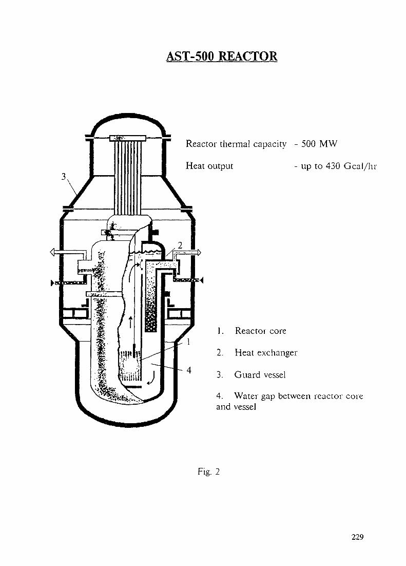
AST-500 REACTOR
Reactor thermal capacity - 500 MW
Heat output - up to 430 Gcal/hr
1. Reactor core
2. Heat exchanger
3. Guard vessel
4. Water gap between reactor coreand vessel
Fig. 2
229

IRRADIATION LEVELS FROM THE EQUIPMENT OFAST, VPBER INTEGRAL REACTORS AND PWR-TYPE
REACTOR
Equipment
Reactor vessel:inner sideouter side
Guard vessel
Reactor concretesilo lining
Reactor siloconcrete
Dose rate, nSv/s
AST-500
16010
10
20
0,2
VPBER-600
33017
14
14
0,15
WER-1000
~3000000~60000
-
~25000
~200
Fig. 3
A characteristic feature of these reactors, the integral layout, which allows thearrangement of the main reactor equipment in one vessel separated from the core (neutronsource) by a thick water layer, ensures low neutron fluence to the reactor vessel andlow induced activity of the main metal-intensive equipment - reactor vessel, guard vesseland structures in the concrete reactor silo, and, hence, low irradiation levels after shutdown(Fig.3).
Already 1 year after plant decommissioning personnel can work in the reactor silowithout protective measures during the whole working day (including dismounting of suchmetal-intensive equipment as the reactor and guard vessels). In this case the maximumirradiation dose rate in the reactor silo in the area of the core is 0.05 mSv/hr(Fig-s 4, 5).
The maximum induced activity in the main and guard vessel and concrete structuresof the VPBER-600 reactor does not exceed 50 Ci and of The AST-500 reactor -15 Ci.
So, this AST and VPBER reactor design property defines their decommissioningconcept - "immediate" disassembly in 1-3 years after shutdown (following terminationof preparatory work).
230

IRRADIATION LEVELS AT VPBER-600DECOMMISSIONING
Concretereactor
siloFig. 4
231

IRRADIATION LEVELS AT AST-500DECOMMISSIONING
Fig. 5
232

3. REDUCED AMOUNT OF RADIOACTIVE CORROSION DEPOSITS
The AST and VPBER plants also show a low activits in the primary coolant causedby corrosion products and, inturn, low. surface contaminat ion of equipment because ofthe application of slightly activated materials corrosion-res'siani for core and heatexchange equipment.
4. INTEGRAL REACTOR DECOMMISSIONING
Reactor plant decommissioning starts at unloading of spent fuel and internals.Unloading of fuel assemblies and dismounting of radioactive internals do not requirespecial devices and do not limit methods and the time needed for decommissioning work,because equipment from the reactor is dismounted and unloaded by means of standardplant facilities used during operation (Fig 6).
At the same stage (calculated for 1-3 years) shghth activated and clean equipmentis dismounted and disassembled, if it is not needed for the following operation stages.
The secondary stage of work (1-2 years duration) is associated with dismounting,disassembly and removal of reactor plant hot equipment from the plant site.
Slightly activated equipment is disassembled by conventional general industrialmethods under control of the radiological safety service, and special facilities andmechanisms are not required.
Hot equipment is broken into fragments by means of remotely controlled manipulatorsin the concrete silos of the plant
Fragments are packed into protective transport fasks and removed to regionalradwaste store.
Spent fuel assemblies in special van-containers are transported to fuel reprocessingplants.
The last stage (1-3 years) is decommissioning of the whole plant including buildingstructures.
5. EVALUATION OF THE AMOUNT OF RADWASTE AT THE TIME OFINTEGRAL REACTOR DECOMMISSIONING
Radioactive equipment and structures of AST and VPBER plants can be dividedin contaminations groups according to their accumulated activity (in correspondence withnational radiological safety norms, that allows evaluation of mass, volume and methodsof handling (Fig-s 7, 8).
The hot equipment and structure mass (in-vessel barrel, guide tubes-connectingdevice unit, etc.) is -60 t for AST and -90 t for VPBER, the medium equipment mass(reactor vessel, heat exchange equipment, etc.) is -270 t for AST and -1850 t forVPBER, the cold and clean equipment mass (guard vessel, concrete reactor silo structures,etc.) is -1000 t for AST and -3750 t for VPBER.
Liquid radwaste formed during cleaning of the circuit water, the reactor andequipment decontamination (liquid radwaste activity does not exceed 1000 CO shouldbe reprocessed - it is evaporated, concentrated and bituminized (AST-500) or cementated(VPBER-600) to confine the activity.
Solid radwaste is also reprocessed it is ground, burnt, pressed and sintered Itsubstantially decreases the total volume of radwaste
233

Refuellingmachine
Fuelassembly
Protectivecask
Equi pmentparting
mani pulator r
Fuel assembly and internals reloading
Cuttei
In-vesselbarrel
Lifting-and-conveyingmachine
Transportcask
In-vesselequipment parts
Parting of in-vessel equipment
Packing of in-vessel equipment partsinto transport cask for removal
and disposal
Fis. 6
234
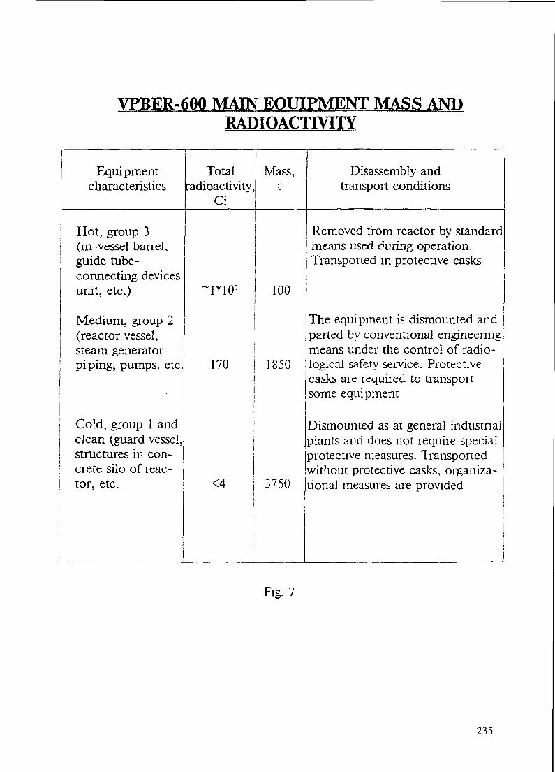
VPBER-600 MAIN EQUIPMENT MASS ANDRADIOACTIVITY
Equipmentcharacteristics
Totalradioactivity,
Ci
Mass,t
Disassembly andtransport conditions
Hot, group 3(in-vessel barrel,guide tube-connecting devicesunit, etc.)
Medium, group 2(reactor vessel,steam generatorpiping, pumps, etc
Cold, group 1 andclean (guard vessel,structures in con-crete silo of reac-tor, etc.
1*107 100
170 1850
<4 ! 3750
Removed from reactor by standardmeans used during operation.Transported in protective casks
The equipment is dismounted andparted by conventional engineeringmeans under the control of radio-logical safety service. Protectivecasks are required to transportsome equi pment
Dismounted as at general industrialplants and does not require specialprotective measures. Transportedwithout protective casks, organiza-tional measures are provided
Fig. 7
235

AST-500 MAIN EQUIPMENT MASS ANDRADIOACTIVITY
Equipmentcharacteristics
Hot, group 3(in-vessel barrel,guide tube-connecting devicesunit, etc.)
Medium, group 2(reactor vessel,heat exchangerpiping, etc.
Cold, group 1 andclean (guard vessel,structures in con-crete silo of reac-tor, etc.
Totalradioactivity,
Ci
~1*106
80
1-2
Mass,t
60
270
980
Disassembly andtransport conditions
Removed from reactor by standardmeans used during operation.Transported in protective casks
j
The equipment is dismounted and jparted by conventional engineeringmeans under the control of radio-logical safety service. Protectivecasks are required ro transportsome equipment
Dismounted as at general industrialplants and does not require specialprotective measures. Transportedwithout protective casks, organiza- •.tional measures are provided
!
Fig. 8
236

VPBER-600 AND WER-440 (NPF'LQVISA") REAC-TOR UNIT DECOMMISSIONING CONDITIONS
Parameters VPBER-600 WER-440 (Atomnaya energiya,v.67, is.2 Aug., 1989)
Power, MW(e)
Service time, years
Hold-up timefollowing reactorshutdown, years
Reactor vesselradioactivity, Ci
Total radioactivity,Ci
Irradiation doserate in reactor silo,mSv/hr
Radioactive wasteamount, t
Collectiveirradiation dose forpersonnel,man.Sv
630
60
50
~105
(without internals)
0.05
2200
2,5
470
30
7000
~1.3*106
(without internals and steelcassette-screens)
130
8460(for 2 units)
23(for 2 units)
Fig. 9
237

6. IRRADIATION DOSE EVALUATION DURING INTEGRAL REACTORDECOMMISSIONING
Because the activity and mass of radioactive equipment of the integral reactorsconsidered are substantially lower than those ones of conventional NPP reactors, thisinfluences irradiation doses.
According to calculations personnel irradiation dose during VPBER-600 andAST-500 unit decommissioning is 2.5-3.5 man.Sv taking account of plani-le\el systems).
The radiological effect on the inhabitants during decommissioning was evaluatedproceeding from the amount of radioactive product releases which can enter theatmosphere. The result obtained was that during AST-500 equipment and reactor vesseldisassembly the reactivity release to the atmosphere including cleaning in wet scrubbersand aerosol filters gives the value ~3 mCi for Co 60, that is -20% of the specifiedlimit.
7. COMPARISON OF DECOMMISSIONING CONDITIONS FOR INTEGRAL ANDVVER-TYPE REACTORS
The advantages of integral reactor decommissioning emerge when comparingdecommissioning conditions for VPBER-600 and VVER-440 "Lovisa" (Fig.9).
The concept of "immediate" dismounting in 2 years following termination ofpreparatory work is suggested both for "Lovisa" and VPBER-600 reactors. The mainproblem of NPP "Lovisa" decommissioning is the handling of the hot reactor vessel whichmust be broken up in hot chambers by remotely controlled equipment and be removedin large thick-walled casks to stores or the reactor vessel and equipment must be removedand disposed off as a whole. One should note that special manipulators and otherexpensive facilities are not required for breaking up the VPBER-600 reactor vessel.
Comparison results show that in spite of higher power a more prolonged operationperiod and shorter hold-up time following shutdown, safety characteristics (activity value,radwaste amount, irradiation doses) during VPBER-600 reactor decommissioning are tensand hundreds times smaller than those for VVER-440 reactor.
8. CONCLUSION
So, the structural features of AST and VPBER reactors (including the integral layoutof their main primary equipment and location of a leaktighr reactor in an additionalguard vessel) ultimately simplify the technologically difficult, radiologically dangerous andexpensive decommissioning of PWR (VVER)-type NPP reduce the amount of radwasteand the costs and make integral reactor decommissioning safe for both personnel andinhabitants.
238

Achkasov, A.N.
Adamovich, L.A.
Al-Mugrabi, M.A.(Scientific Secretary)
Altshuller, M.
Antariksawan, A.R.
Baranaev, Yu.D.
Boado, H. M.
Buhtoyarov, A.V.
LIST OF PARTICIPANTS
Research and Development Institute of PowerEngineering (RDIPE)Malaya Krasnoselskaya st. h. 2/8MoscowRussian Federation
Research and Development Institute of PowerEngineering (RDIPE)Malaya Krasnoselskaya st. h. 2/8MoscowRussian Federation
IAEA, Division of Nuclear PowerWagramerstrasse -5P.O. Box 100A-1400 Vienna, Austria
All-Union Research Institute for Nuclear PowerPlant OperationsFerganskaya 25109507 MoscowRussian Federation
Nattional Atomic Energy Agency (BATAN)Kawasan Puspiptek SerpongTangerang 15310Indonesia
Institute of Physics and Power Engineering (IPPE)Bondarenko Sq. 1249020 ObninskRussian Federation
INVAP S.E.Moreno 2089San Carlos de Bariloche(CP 8400), Argentina
EDO "Gidropress"Ordzhonikidze st. 21142103 Moscow DistrictPonolskRussian Federation
239

Cinotti, L.
Dolgov, V.N.
Dolgov, V.V.
Dzhusow, Y.
Erastov, A.
Gibson, I.
Grachev, N.
Grechko, G.I.
Grigoriev, O.
Advanced Reactors Project EngineerANSALDONuclear DivisionCorso Perrone 2516161 Geneva, Italy
St. Petersburgh Marine Engineering Bureau "Malachite'Frunze Str. 18196135 St. PetersburgRussian Federation
Institute of Physics and Power Engineering (IPPE)Bondarenko Sq. 1249020 ObninskRussian Federation
Institute of Physics and Power Engineering (IPPE)Bondarenko Sq. 1249020 ObninskRussian Federation
MINATOMStaromonetny pereulok 26109180 MoscowRussian Federation
3, Hardy CloseMartinstown, DorchesterDT2 9JS DorsetUnited Kingdom
Institute of Physics and Power Engineering (IPPE)Bondarenko Sq. 1249020 ObninskRussian Federation
Research and Development Institute of PowerEngineering (RDIPE)Malaya Krasnoselskaya st. h. 2/8MoscowRussian Federation
Institute of Physics and Power Engineering (IPPE)Bondarenko Sq. 1249020 ObninskRussian Federation
240

Hey, H.M.
Kalyakin, S.
Kirn, J.I.
Kozmenkov, Y.K.
Kusmartsev, E.
Kuul, V.
Kuzachenkov, A.B.
Lapin, D.B.
Leger, A.
Lee, D.
CNEAAv. Libertador 82501429 Buenos AiresArgentina
Institute of Physics and Power Engineering (IPPE)Bondarenko Sq. 1249020 ObninskRussian Federation
Korea Atomic Energy Research Institute (KAERI)P.O. Box 105, YusungTaejon 305-606Republic of Korea
Institute of Physics and Power Engineering (IPPE)Bondarenko Sq. 1249020 ObninskRussian Federation
OKB Mechanical EngineeringBurnakovsky proezd 15603074 Nizhny NovgorodRussian Federation
OKB Mechanical EngineeringBurnakovsky proezd 15603074 Nizhny NovgorodRussian Federation
OKB Mechanical EngineeringBurnakovsky proezd 15603074 Nizhny NovgorodRussian Federation
Research and Development Institute of PowerEngineering (RDIPE)Malaya Krasnoselskaya st. h. 2/8Moscow, Russian Federation
TECHNICATOMEBP 17, 91192 Gif-sur-YvetteFrance
Korea Atomic Energy Research Institute (KAERI)P.O. Box 105, YusungTaejon 305-606Republic of Korea
241

Leonchyk, M.
Li, M.
Lusanova, L.M.
Ma, C.
Nikiporets, Yu.G.
Nikolaeva, A.N.
Orekhov, Y.I.
Pepa, V.N.
Pokrovskaya, I.N.
Institute of Physics and Power Engineering (IPPE)Bondarenko Sq. 1249020 ObninskRussian Federation
Nuclear Power Institute of ChinaP.O. Box 436-500Chengdu, Sichuan ProvinceChina
Russian Research Centre"Kurchatov Institute"Kurchatov Square123182 MoscowRussian Federation
Institute of Nuclear Energy TechnologyTsinghua University100084 BeijingChina
Russian Research Centre"Kurchatov Institute"Kurchatov Square123182 MoscowRussian Federation
St. Petersburgh Marine Engineering Bureau "Malachite"Frunze Str. 18196135 St. PetersburgRussian Federation
Institute of Physics and Power Engineering (IPPE)Bondarenko Sq. 1249020 ObninskRussian Federation
Research and Development Institute of PowerEngineering (RDIPE)Malaya Krasnoselskaya st. h. 2/8MoscowRussian Federation
Research and Development Institute of PowerEngineering (RDIPE)Malaya Krasnoselskaya st. h. 2/8MoscowRussian Federation
242
Rulev, V.
Sergeev, Yu. A.
Shumsky, R.
Shvedenko, I.
Skorikov, D.
Vitin, S.
Vorobev, V.
Yamaji, A.
Zverev, K.
OKB Mechanical EngineeringBurnakovsky proezd 15603074 Nizhny NovgorodRussian Federation
Institute of Physics and Power Engineering (IPPE)Bondarenko Sq. 1249020 ObninskRussian Federation
Institute of Physics and Power Engineering (IPPE)Bondarenko Sq. 1249020 ObninskRussian Federation
Institute of Physics and Power Engineering (IPPE)Bondarenko Sq. 1249020 ObninskRussian Federation
Institute of Physics and Power Engineering (IPPE)Bondarenko Sq. 1249020 ObninskRussian Federation
Research Technology Institute188537 Sosnovy BorLeningrad RegionRussian Federation
"Baltsudoproject"Griboedova canal 90St. PetersburgRussian Federation
Japan Atomic Energy ResearchInstitute - JAERITokai-mura, Naka-gun, Ibaraki-ken319-11 Japan
Russian Federation Ministry for Atomic EnergyStaromonetny pereulok 26109180 MoscowRussian Federation
243


![Improving economics and safety of water cooled … Nuclear power plants (NPPs) with water cooled reactors [either light water reactors (LWRs) or heavy water reactors (HWRs)] constitute](https://static.fdocuments.us/doc/165x107/5b88e5437f8b9a46538ebfc1/improving-economics-and-safety-of-water-cooled-nuclear-power-plants-npps-with.jpg)
