INTECRIO V4.7 User’s Guide
178
www.etas.com INTECRIO V4.7 User’s Guide
Transcript of INTECRIO V4.7 User’s Guide
www.etas.com
INTECRIO V4.7User’s Guide

Copyright
The data in this document may not be altered or amended without special noti-fication from ETAS GmbH. ETAS GmbH undertakes no further obligation in relation to this document. The software described in it can only be used if the customer is in possession of a general license agreement or single license. Using and copying is only allowed in concurrence with the specifications stipulated in the contract.
Under no circumstances may any part of this document be copied, reproduced, transmitted, stored in a retrieval system or translated into another language without the express written permission of ETAS GmbH.
© Copyright 2020 ETAS GmbH, Stuttgart
The names and designations used in this document are trademarks or brands belonging to the respective owners.
The name INTECRIO is a registered trademark of ETAS GmbH.
MATLAB and Simulink are registered trademarks of The MathWorks, Inc.
INTECRIO V4.7 - User’s Guide R04 EN - 06.2020

ETAS Contents
Contents
1 About this Document . . . . . . . . . . . . . . . . . . . . . . . . . . . . . . . . . . . . . . . . . . . . . . . . . . . 71.1 Classification of Safety Messages . . . . . . . . . . . . . . . . . . . . . . . . . . . . . . . . . . . . . . . . . . 7
1.2 Presentation of Instructions . . . . . . . . . . . . . . . . . . . . . . . . . . . . . . . . . . . . . . . . . . . . . . . 7
1.3 Typographical Conventions . . . . . . . . . . . . . . . . . . . . . . . . . . . . . . . . . . . . . . . . . . . . . . . . 8
1.4 Presentation of Supporting Information . . . . . . . . . . . . . . . . . . . . . . . . . . . . . . . . . . . . . 8
2 Introduction. . . . . . . . . . . . . . . . . . . . . . . . . . . . . . . . . . . . . . . . . . . . . . . . . . . . . . . . . . . 9
2.1 Safety Information . . . . . . . . . . . . . . . . . . . . . . . . . . . . . . . . . . . . . . . . . . . . . . . . . . . . . . . 92.1.1 Correct Use . . . . . . . . . . . . . . . . . . . . . . . . . . . . . . . . . . . . . . . . . . . . . . . . . . . . . 92.1.2 Demands on the Technical State of the Product . . . . . . . . . . . . . . . . . . . . . 9
2.2 Privacy Statement . . . . . . . . . . . . . . . . . . . . . . . . . . . . . . . . . . . . . . . . . . . . . . . . . . . . . . . 102.2.1 Data Processing . . . . . . . . . . . . . . . . . . . . . . . . . . . . . . . . . . . . . . . . . . . . . . . . 102.2.2 Data and Data Categories. . . . . . . . . . . . . . . . . . . . . . . . . . . . . . . . . . . . . . . . 102.2.3 Technical and Organizational Measures . . . . . . . . . . . . . . . . . . . . . . . . . . . 11
3 Understanding INTECRIO . . . . . . . . . . . . . . . . . . . . . . . . . . . . . . . . . . . . . . . . . . . . . 12
3.1 Challenges of the Electronic Control Unit Development. . . . . . . . . . . . . . . . . . . . . . . 133.1.1 Complexity Through System Requirements . . . . . . . . . . . . . . . . . . . . . . . . 133.1.2 Complexity Through Distributed Development. . . . . . . . . . . . . . . . . . . . . . 153.1.3 Possible Steps . . . . . . . . . . . . . . . . . . . . . . . . . . . . . . . . . . . . . . . . . . . . . . . . . 16
3.2 Description of Electronic Systems . . . . . . . . . . . . . . . . . . . . . . . . . . . . . . . . . . . . . . . . . 163.2.1 Design and Operating Method of Electronic Systems . . . . . . . . . . . . . . . 173.2.2 Architecture and Description of Electronic Systems. . . . . . . . . . . . . . . . . 18
3.2.2.1 Application Software. . . . . . . . . . . . . . . . . . . . . . . . . . . . . . . . . . 203.2.2.2 Platform Software: Hardware Systems. . . . . . . . . . . . . . . . . . 233.2.2.3 Connecting Hardware and Software . . . . . . . . . . . . . . . . . . . . 23
3.3 Virtual Prototyping. . . . . . . . . . . . . . . . . . . . . . . . . . . . . . . . . . . . . . . . . . . . . . . . . . . . . . . 243.3.1 Target-Close Prototyping . . . . . . . . . . . . . . . . . . . . . . . . . . . . . . . . . . . . . . . . 253.3.2 Advantages of Virtual Prototyping . . . . . . . . . . . . . . . . . . . . . . . . . . . . . . . . 253.3.3 Virtual Prototyping and Rapid Prototyping . . . . . . . . . . . . . . . . . . . . . . . . . 26
3.4 INTECRIO in the Development Process. . . . . . . . . . . . . . . . . . . . . . . . . . . . . . . . . . . . . 27
3.5 The INTECRIO Working Environment. . . . . . . . . . . . . . . . . . . . . . . . . . . . . . . . . . . . . . . 283.5.1 Software Systems . . . . . . . . . . . . . . . . . . . . . . . . . . . . . . . . . . . . . . . . . . . . . . 32
3.5.1.1 Modules and AUTOSAR Software Components . . . . . . . . . . 323.5.1.2 Functions . . . . . . . . . . . . . . . . . . . . . . . . . . . . . . . . . . . . . . . . . . . 343.5.1.3 Software Systems . . . . . . . . . . . . . . . . . . . . . . . . . . . . . . . . . . . . 35
3.5.2 Environment Systems . . . . . . . . . . . . . . . . . . . . . . . . . . . . . . . . . . . . . . . . . . . 353.5.3 Hardware Systems . . . . . . . . . . . . . . . . . . . . . . . . . . . . . . . . . . . . . . . . . . . . . 363.5.4 System Projects . . . . . . . . . . . . . . . . . . . . . . . . . . . . . . . . . . . . . . . . . . . . . . . . 363.5.5 Crossbar . . . . . . . . . . . . . . . . . . . . . . . . . . . . . . . . . . . . . . . . . . . . . . . . . . . . . . 38
3.6 Experimenting with INTECRIO. . . . . . . . . . . . . . . . . . . . . . . . . . . . . . . . . . . . . . . . . . . . . 40
4 INTECRIO and AUTOSAR. . . . . . . . . . . . . . . . . . . . . . . . . . . . . . . . . . . . . . . . . . . . . . 42
4.1 Overview . . . . . . . . . . . . . . . . . . . . . . . . . . . . . . . . . . . . . . . . . . . . . . . . . . . . . . . . . . . . . . . 42
INTECRIO V4.7 - User’s Guide 3
ETAS Contents
4.1.1 RTA-RTE and RTA-OS . . . . . . . . . . . . . . . . . . . . . . . . . . . . . . . . . . . . . . . . . . . 434.1.2 Creating AUTOSAR Software Components (outside INTECRIO) . . . . . . 444.1.3 Validating Software Components . . . . . . . . . . . . . . . . . . . . . . . . . . . . . . . . . 44
4.2 What is a Runtime Environment? . . . . . . . . . . . . . . . . . . . . . . . . . . . . . . . . . . . . . . . . . . 46
4.3 AUTOSAR Elements in INTECRIO. . . . . . . . . . . . . . . . . . . . . . . . . . . . . . . . . . . . . . . . . . 474.3.1 AUTOSAR Software Components. . . . . . . . . . . . . . . . . . . . . . . . . . . . . . . . . 474.3.2 Ports and Interfaces . . . . . . . . . . . . . . . . . . . . . . . . . . . . . . . . . . . . . . . . . . . . 48
4.3.2.1 Sender-Receiver Communication. . . . . . . . . . . . . . . . . . . . . . . 484.3.2.2 Client-Server Communication . . . . . . . . . . . . . . . . . . . . . . . . . . 494.3.2.3 Calibration Parameter Interfaces . . . . . . . . . . . . . . . . . . . . . . . 49
4.3.3 Runnable Entities and Tasks . . . . . . . . . . . . . . . . . . . . . . . . . . . . . . . . . . . . . 494.3.4 Runtime Environment . . . . . . . . . . . . . . . . . . . . . . . . . . . . . . . . . . . . . . . . . . . 50
5 The INTECRIO Components . . . . . . . . . . . . . . . . . . . . . . . . . . . . . . . . . . . . . . . . . . . 51
5.1 MATLAB® and Simulink® Connectivity . . . . . . . . . . . . . . . . . . . . . . . . . . . . . . . . . . . . . 525.1.1 Characteristics in the Creation of the Simulink Model . . . . . . . . . . . . . . . 545.1.2 Contents of the Description File . . . . . . . . . . . . . . . . . . . . . . . . . . . . . . . . . . 55
5.2 ASCET Connectivity. . . . . . . . . . . . . . . . . . . . . . . . . . . . . . . . . . . . . . . . . . . . . . . . . . . . . . 555.2.1 Characteristics in the Creation of the ASCET Model . . . . . . . . . . . . . . . . . 565.2.2 Contents of the Description File . . . . . . . . . . . . . . . . . . . . . . . . . . . . . . . . . . 57
5.3 The Hardware Configurator . . . . . . . . . . . . . . . . . . . . . . . . . . . . . . . . . . . . . . . . . . . . . . . 575.3.1 Discontinued Hardware . . . . . . . . . . . . . . . . . . . . . . . . . . . . . . . . . . . . . . . . . 585.3.2 HWX Import/Export . . . . . . . . . . . . . . . . . . . . . . . . . . . . . . . . . . . . . . . . . . . . . 595.3.3 Ethernet Controller and XCP on UDP . . . . . . . . . . . . . . . . . . . . . . . . . . . . . . 605.3.4 XXX to CAN Gateway. . . . . . . . . . . . . . . . . . . . . . . . . . . . . . . . . . . . . . . . . . . . 60
5.4 ES900 Connectivity and Hardware Configurator . . . . . . . . . . . . . . . . . . . . . . . . . . . . . 605.4.1 ES900 Configuration in the Hardware Configurator . . . . . . . . . . . . . . . . . 615.4.2 Interface Types and Supported Interfaces . . . . . . . . . . . . . . . . . . . . . . . . . 65
5.5 ES800 Connectivity and Hardware Configurator . . . . . . . . . . . . . . . . . . . . . . . . . . . . . 725.5.1 ES800 Configuration in the Hardware Configurator . . . . . . . . . . . . . . . . . 735.5.2 Interface Types and Supported Interfaces . . . . . . . . . . . . . . . . . . . . . . . . . 77
5.6 PC Connectivity . . . . . . . . . . . . . . . . . . . . . . . . . . . . . . . . . . . . . . . . . . . . . . . . . . . . . . . . . 84
5.7 The Project Configurator . . . . . . . . . . . . . . . . . . . . . . . . . . . . . . . . . . . . . . . . . . . . . . . . . 855.7.1 Offline Mode . . . . . . . . . . . . . . . . . . . . . . . . . . . . . . . . . . . . . . . . . . . . . . . . . . . 86
5.7.1.1 Modules and SWC. . . . . . . . . . . . . . . . . . . . . . . . . . . . . . . . . . . . 865.7.1.2 Functions . . . . . . . . . . . . . . . . . . . . . . . . . . . . . . . . . . . . . . . . . . . 865.7.1.3 Software Systems and Environments . . . . . . . . . . . . . . . . . . . 875.7.1.4 System Projects. . . . . . . . . . . . . . . . . . . . . . . . . . . . . . . . . . . . . . 88
5.7.2 Online Mode . . . . . . . . . . . . . . . . . . . . . . . . . . . . . . . . . . . . . . . . . . . . . . . . . . . 89
5.8 The OS Configurator . . . . . . . . . . . . . . . . . . . . . . . . . . . . . . . . . . . . . . . . . . . . . . . . . . . . . 905.8.1 Tasks of the Operating System . . . . . . . . . . . . . . . . . . . . . . . . . . . . . . . . . . . 90
5.8.1.1 Scheduling . . . . . . . . . . . . . . . . . . . . . . . . . . . . . . . . . . . . . . . . . . 915.8.1.2 Tasks . . . . . . . . . . . . . . . . . . . . . . . . . . . . . . . . . . . . . . . . . . . . . . . 915.8.1.3 Cooperative and Preemptive Scheduling . . . . . . . . . . . . . . . . 925.8.1.4 Data Consistency with Preemptive Scheduling . . . . . . . . . . . 945.8.1.5 Application Modes. . . . . . . . . . . . . . . . . . . . . . . . . . . . . . . . . . . . 96
INTECRIO V4.7 - User’s Guide 4
ETAS Contents
5.8.2 Design of the OS Configurator . . . . . . . . . . . . . . . . . . . . . . . . . . . . . . . . . . . . 975.8.3 The OSC Editor . . . . . . . . . . . . . . . . . . . . . . . . . . . . . . . . . . . . . . . . . . . . . . . . . 98
5.8.3.1 Creating Tasks . . . . . . . . . . . . . . . . . . . . . . . . . . . . . . . . . . . . . . . 985.8.3.2 Task Properties . . . . . . . . . . . . . . . . . . . . . . . . . . . . . . . . . . . . . 1015.8.3.3 Setting Up Timer and Software Tasks. . . . . . . . . . . . . . . . . . 1035.8.3.4 Setting Up Interrupt Service Routines . . . . . . . . . . . . . . . . . . 104
5.9 The Project Integrator . . . . . . . . . . . . . . . . . . . . . . . . . . . . . . . . . . . . . . . . . . . . . . . . . . . 1065.9.1 The Build Process . . . . . . . . . . . . . . . . . . . . . . . . . . . . . . . . . . . . . . . . . . . . . 106
5.9.1.1 Overview . . . . . . . . . . . . . . . . . . . . . . . . . . . . . . . . . . . . . . . . . . . 1075.9.1.2 Sequence . . . . . . . . . . . . . . . . . . . . . . . . . . . . . . . . . . . . . . . . . . 108
5.9.2 ASAM-MCD-2MC Generation. . . . . . . . . . . . . . . . . . . . . . . . . . . . . . . . . . . . 109
5.10 The ETAS Experiment Environment . . . . . . . . . . . . . . . . . . . . . . . . . . . . . . . . . . . . . . . 1105.10.1 Validation and Verification . . . . . . . . . . . . . . . . . . . . . . . . . . . . . . . . . . . . . . 1115.10.2 Measuring and Calibrating . . . . . . . . . . . . . . . . . . . . . . . . . . . . . . . . . . . . . . 1115.10.3 Experimenting with Different Targets. . . . . . . . . . . . . . . . . . . . . . . . . . . . . 1125.10.4 Rapid Prototyping Experiment with the ETAS Experiment
Environment . . . . . . . . . . . . . . . . . . . . . . . . . . . . . . . . . . . . . . . . . . . . . . . . . . .1155.10.4.1 Bypass Experiment . . . . . . . . . . . . . . . . . . . . . . . . . . . . . . . . . . 1155.10.4.2 Fullpass Experiment . . . . . . . . . . . . . . . . . . . . . . . . . . . . . . . . . 1165.10.4.3 X-Pass Experiment . . . . . . . . . . . . . . . . . . . . . . . . . . . . . . . . . . 118
5.10.5 Virtual Prototyping Experiments with the ETAS Experiment Environment . . . . . . . . . . . . . . . . . . . . . . . . . . . . . . . . . . . . . . . . . . . . . . . . . . .118
5.11 The Documentor . . . . . . . . . . . . . . . . . . . . . . . . . . . . . . . . . . . . . . . . . . . . . . . . . . . . . . . 118
5.12 RTA-TRACE Connectivity . . . . . . . . . . . . . . . . . . . . . . . . . . . . . . . . . . . . . . . . . . . . . . . . 119
6 SCOOP and SCOOP-IX . . . . . . . . . . . . . . . . . . . . . . . . . . . . . . . . . . . . . . . . . . . . . . . 120
6.1 The SCOOP Concept . . . . . . . . . . . . . . . . . . . . . . . . . . . . . . . . . . . . . . . . . . . . . . . . . . . . 121
6.2 The SCOOP-IX Language . . . . . . . . . . . . . . . . . . . . . . . . . . . . . . . . . . . . . . . . . . . . . . . . 1216.2.1 Modules and Interfaces . . . . . . . . . . . . . . . . . . . . . . . . . . . . . . . . . . . . . . . . 1226.2.2 Description of the C Code Interface . . . . . . . . . . . . . . . . . . . . . . . . . . . . . . 1226.2.3 Description of Semantic Information . . . . . . . . . . . . . . . . . . . . . . . . . . . . . 123
6.2.3.1 Model Origin . . . . . . . . . . . . . . . . . . . . . . . . . . . . . . . . . . . . . . . . 1236.2.3.2 Implementation . . . . . . . . . . . . . . . . . . . . . . . . . . . . . . . . . . . . . 1256.2.3.3 Use . . . . . . . . . . . . . . . . . . . . . . . . . . . . . . . . . . . . . . . . . . . . . . . . 1266.2.3.4 Module Data . . . . . . . . . . . . . . . . . . . . . . . . . . . . . . . . . . . . . . . . 126
6.2.4 Referenced Models . . . . . . . . . . . . . . . . . . . . . . . . . . . . . . . . . . . . . . . . . . . . 1276.2.4.1 Extract from a *.six File . . . . . . . . . . . . . . . . . . . . . . . . . . . . 1276.2.4.2 Extract from a *.ref_six File . . . . . . . . . . . . . . . . . . . . . . . 130
6.3 Creation of SCOOP-IX and Example . . . . . . . . . . . . . . . . . . . . . . . . . . . . . . . . . . . . . . . 132
7 Modeling Hints . . . . . . . . . . . . . . . . . . . . . . . . . . . . . . . . . . . . . . . . . . . . . . . . . . . . . 142
7.1 Modeling for INTECRIO. . . . . . . . . . . . . . . . . . . . . . . . . . . . . . . . . . . . . . . . . . . . . . . . . . 142
7.2 Modeling with Simulink. . . . . . . . . . . . . . . . . . . . . . . . . . . . . . . . . . . . . . . . . . . . . . . . . . 142
7.3 Modeling with ASCET . . . . . . . . . . . . . . . . . . . . . . . . . . . . . . . . . . . . . . . . . . . . . . . . . . . 144
7.4 Integration of User Code . . . . . . . . . . . . . . . . . . . . . . . . . . . . . . . . . . . . . . . . . . . . . . . . 144
INTECRIO V4.7 - User’s Guide 5

ETAS Contents
8 Bypass Concept . . . . . . . . . . . . . . . . . . . . . . . . . . . . . . . . . . . . . . . . . . . . . . . . . . . . 145
8.1 ETK Bypass Concept Description . . . . . . . . . . . . . . . . . . . . . . . . . . . . . . . . . . . . . . . . . 145
8.2 Bypass Input . . . . . . . . . . . . . . . . . . . . . . . . . . . . . . . . . . . . . . . . . . . . . . . . . . . . . . . . . . . 145
8.3 Hook-Based Bypass . . . . . . . . . . . . . . . . . . . . . . . . . . . . . . . . . . . . . . . . . . . . . . . . . . . . 146
8.4 Service-Based Bypass. . . . . . . . . . . . . . . . . . . . . . . . . . . . . . . . . . . . . . . . . . . . . . . . . . . 147
8.5 Safety Considerations. . . . . . . . . . . . . . . . . . . . . . . . . . . . . . . . . . . . . . . . . . . . . . . . . . . 1498.5.1 Bypass Input Data . . . . . . . . . . . . . . . . . . . . . . . . . . . . . . . . . . . . . . . . . . . . . 1498.5.2 Bypass Calculation . . . . . . . . . . . . . . . . . . . . . . . . . . . . . . . . . . . . . . . . . . . . 1498.5.3 Bypass Output Data. . . . . . . . . . . . . . . . . . . . . . . . . . . . . . . . . . . . . . . . . . . . 1498.5.4 Message Copies. . . . . . . . . . . . . . . . . . . . . . . . . . . . . . . . . . . . . . . . . . . . . . . 149
8.6 Service-Based Bypass Specifics . . . . . . . . . . . . . . . . . . . . . . . . . . . . . . . . . . . . . . . . . . 1508.6.1 Service Processes for the SBB Implemented as Service Functions. . . 1518.6.2 Controlling the ECU Behavior from INTECRIO . . . . . . . . . . . . . . . . . . . . . 1528.6.3 OS Configuration for Service-Based Bypass V3 . . . . . . . . . . . . . . . . . . . . 152
8.6.3.1 Restrictions. . . . . . . . . . . . . . . . . . . . . . . . . . . . . . . . . . . . . . . . . 1528.6.3.2 Classical ECU Function Bypass . . . . . . . . . . . . . . . . . . . . . . . 1538.6.3.3 Bypass of an Entire ECU Functionality . . . . . . . . . . . . . . . . . 1548.6.3.4 Read and Write Actions of the Same Service Point in
Different Rasters . . . . . . . . . . . . . . . . . . . . . . . . . . . . . . . . . . . .1558.6.3.5 ECU-Synchronous Write-Back. . . . . . . . . . . . . . . . . . . . . . . . . 157
8.6.4 Summary . . . . . . . . . . . . . . . . . . . . . . . . . . . . . . . . . . . . . . . . . . . . . . . . . . . . . 158
9 Glossary. . . . . . . . . . . . . . . . . . . . . . . . . . . . . . . . . . . . . . . . . . . . . . . . . . . . . . . . . . . 160
9.1 Abbreviations . . . . . . . . . . . . . . . . . . . . . . . . . . . . . . . . . . . . . . . . . . . . . . . . . . . . . . . . . . 160
9.2 Terms. . . . . . . . . . . . . . . . . . . . . . . . . . . . . . . . . . . . . . . . . . . . . . . . . . . . . . . . . . . . . . . . . 164
10 Contact Information. . . . . . . . . . . . . . . . . . . . . . . . . . . . . . . . . . . . . . . . . . . . . . . . . 169
Figures . . . . . . . . . . . . . . . . . . . . . . . . . . . . . . . . . . . . . . . . . . . . . . . . . . . . . . . . . . . 170
Tables . . . . . . . . . . . . . . . . . . . . . . . . . . . . . . . . . . . . . . . . . . . . . . . . . . . . . . . . . . . . 174
Index . . . . . . . . . . . . . . . . . . . . . . . . . . . . . . . . . . . . . . . . . . . . . . . . . . . . . . . . . . . . . 175
INTECRIO V4.7 - User’s Guide 6

ETAS About this Document
1 About this Document
1.1 Classification of Safety MessagesThe safety messages used here warn of dangers that can lead to personal injury or damage to property:
1.2 Presentation of InstructionsThe target to be achieved is defined in the heading. The necessary steps for his are in a step-by-step guide:
Target definition1. Step 12. Step 23. Step 3> Result
DANGERindicates a hazardous situation with a high risk of death or serious injury if not avoided
WARNINGindicates a hazardous situation of medium risk which could result in death or serious injury if not avoided.
CAUTIONindicates a hazardous situation of low risk which may result in minor or mod-erate injury if not avoided.
NOTICEindicates a situation which may result in damage to property if not avoided.
INTECRIO V4.7 - User’s Guide 7
ETAS About this Document
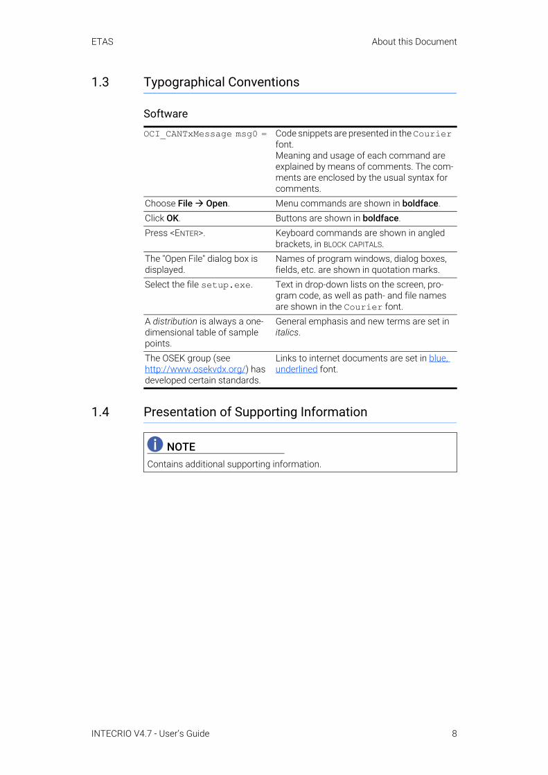
1.3 Typographical Conventions
Software
1.4 Presentation of Supporting Information
OCI_CANTxMessage msg0 = Code snippets are presented in the Courier font.Meaning and usage of each command are explained by means of comments. The com-ments are enclosed by the usual syntax for comments.
Choose File Open. Menu commands are shown in boldface.Click OK. Buttons are shown in boldface.Press <ENTER>. Keyboard commands are shown in angled
brackets, in BLOCK CAPITALS.The "Open File" dialog box is displayed.
Names of program windows, dialog boxes, fields, etc. are shown in quotation marks.
Select the file setup.exe. Text in drop-down lists on the screen, pro-gram code, as well as path- and file names are shown in the Courier font.
A distribution is always a one-dimensional table of sample points.
General emphasis and new terms are set in italics.
The OSEK group (see http://www.osekvdx.org/) has developed certain standards.
Links to internet documents are set in blue, underlined font.
NOTEContains additional supporting information.
INTECRIO V4.7 - User’s Guide 8
ETAS Introduction
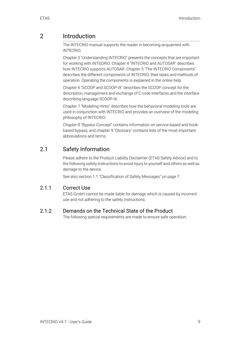
2 IntroductionThe INTECRIO manual supports the reader in becoming acquainted with INTECRIO.
Chapter 3 "Understanding INTECRIO" presents the concepts that are important for working with INTECRIO. Chapter 4 "INTECRIO and AUTOSAR" describes how INTECRIO supports AUTOSAR. Chapter 5 "The INTECRIO Components" describes the different components of INTECRIO, their tasks and methods of operation. Operating the components is explained in the online help.
Chapter 6 "SCOOP and SCOOP-IX" describes the SCOOP concept for the description, management and exchange of C code interfaces and the interface describing language SCOOP-IX.
Chapter 7 "Modeling Hints" describes how the behavioral modeling tools are used in conjunction with INTECRIO and provides an overview of the modeling philosophy of INTECRIO.
Chapter 8 "Bypass Concept" contains information on service-based and hook-based bypass, and chapter 9 "Glossary" contains lists of the most important abbreviations and terms.
2.1 Safety Information Please adhere to the Product Liability Disclaimer (ETAS Safety Advice) and to the following safety instructions to avoid injury to yourself and others as well as damage to the device.
See also section 1.1 "Classification of Safety Messages" on page 7.
2.1.1 Correct UseETAS GmbH cannot be made liable for damage which is caused by incorrect use and not adhering to the safety instructions.
2.1.2 Demands on the Technical State of the ProductThe following special requirements are made to ensure safe operation:
INTECRIO V4.7 - User’s Guide 9

ETAS Introduction
• Take all information on environmental conditions into consideration before setup and operation (see the documentation of your computer, hardware, etc.).
Further safety advice for this ETAS product is available in the following formats:
• In section 8.5 "Safety Considerations" on page 149.• A printed document shipped with the DVD media. • In electronic form on the DVD. See Documentation\ETAS Safety
Advice.pdf for details. • The "ETAS Safety Advice" window that opens when you start the pro-
gram, or when you select Help → ETAS Safety Advice.
2.2 Privacy StatementYour privacy is important to ETAS so we have created the following Privacy Statement that informs you which data are processed in INTECRIO, which data categories INTECRIO uses, and which technical measure you have to take to ensure the users’ privacy. Additionally, we provide further instructions where this product stores and where you can delete personal or personal-related data.
2.2.1 Data ProcessingNote that personal or personal-related data respectively data categories are processed when using this product. The purchaser of this product is responsi-ble for the legal conformity of processing the data in accordance with Article 4 No. 7 of the General Data Protection Regulation (GDPR). As the manufacturer, ETAS GmbH is not liable for any mishandling of this data.
2.2.2 Data and Data CategoriesPlease note that this product creates files containing file names and file paths, e.g. for purposes of error analysis, referencing source libraries, or for communi-cating with third party programs.
The same file names and file paths may contain personal data, if they refer to the current user's personal directory or subdirectories (e.g., C:\Users\ <UserId>\Documents\...).
WARNINGWrongly initialized NVRAM variables can lead to unpredictable behavior of a vehicle or a test bench, and thus to safety-critical situations.INTECRIO systems that use the NVRAM possibilities of the experimental tar-gets expect a user-defined initialization that checks whether all NV variables are valid for the current project, both individually and in combination with other NV variables. If this is not the case, all NV variables have to be initialized with their (reasonable) default values.Due to the NVRAM saving concept, this is absolutely necessary when proj-ects are used in environments where any harm to people and equipment can happen when unsuitable initialization values are used (e.g. in-vehicle-use or at test benches).
INTECRIO V4.7 - User’s Guide 10

ETAS Introduction
Furthermore, using ETAS Rapid Prototyping solutions in test vehicles con-nected to real sensors, buses or ECUs, the ETAS tools may get access to per-sonal data of the driver.
This data can also be stored using dataloggers as provided by INCA-EIP or the ETAS Experiment Environment.
When using the ETAS License Manager in combination with user-based licenses, particularly the following personal or personal-related data respec-tively data categories can be recorded for the purposes of license manage-ment:
• Communication data: IP address• User data: UserID, WindowsUserID
2.2.3 Technical and Organizational MeasuresThis product does not itself encrypt the personal or personal-related data respectively data categories that it records. Ensure that the data recorded are secured by means of suitable technical or organizational measures in your IT system.
Personal or personal-related data in log files can be deleted by tools in the oper-ating system.
INTECRIO V4.7 - User’s Guide 11
ETAS Understanding INTECRIO
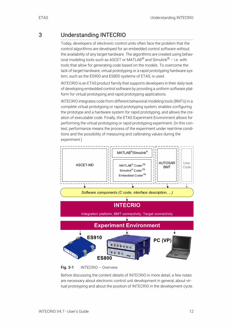
3 Understanding INTECRIOToday, developers of electronic control units often face the problem that the control algorithms are developed for an embedded control software without the availability of any target hardware. The algorithms are created using behav-ioral modeling tools such as ASCET or MATLAB® and Simulink® – i.e. with tools that allow for generating code based on the models. To overcome the lack of target hardware, virtual prototyping or a rapid prototyping hardware sys-tem, such as the ES900 and ES800 systems of ETAS, is used.
INTECRIO is an ETAS product family that supports developers in their daily task of developing embedded control software by providing a uniform software plat-form for virtual prototyping and rapid prototyping applications.
INTECRIO integrates code from different behavioral modeling tools (BMTs) in a complete virtual prototyping or rapid prototyping system, enables configuring the prototype and a hardware system for rapid prototyping, and allows the cre-ation of executable code. Finally, the ETAS Experiment Environment allows for performing the virtual prototyping or rapid prototyping experiment. (In this con-text, performance means the process of the experiment under real-time condi-tions and the possibility of measuring and calibrating values during the experiment.)
Fig. 3-1 INTECRIO – Overview
Before discussing the content details of INTECRIO in more detail, a few notes are necessary about electronic control unit development in general, about vir-tual prototyping and about the position of INTECRIO in the development cycle.
MATLAB®/Simulink®
MATLAB® CoderTM
Simulink® CoderTM
Embedded CoderTMASCET-RP INTECRIO-ASC
AUTOSAR BMT
User Code
Software components (C code, interface description, ...)
ASCET-MD
INTECRIO
Integration platform, BMT connectivity, Target connectivity
Experiment Environment
PC (VP)ES910
ES800
INTECRIO V4.7 - User’s Guide 12
ETAS Understanding INTECRIO
3.1 Challenges of the Electronic Control Unit DevelopmentThe electronic control unit development is a highly complex process: Partly because of the constantly increasing requirements of hardware and software, partly because of the development which is frequently spread across several manufacturers and suppliers.
3.1.1 Complexity Through System RequirementsToday, the complete description of an electronic control unit consists of the description of the software to be run on the electronic control unit and the description of the hardware. In most cases, control algorithms and electronic control unit software are closely linked with the target system on which they are executed.
ASCET introduced the first steps to dissolve this mutual dependency by describing the software (the control algorithm) independently of the hardware on which it is to run. ASCET accomplishes this by mapping the signals from the control algorithm onto the signals supplied by the hardware. If it is a rapid pro-totyping system, the hardware itself is described in a special editor. Different options exist for microcontroller targets.
In the future, this separation of the descriptions of the target hardware and the software will become increasingly more important for the successful imple-mentation of a new electronic control unit.
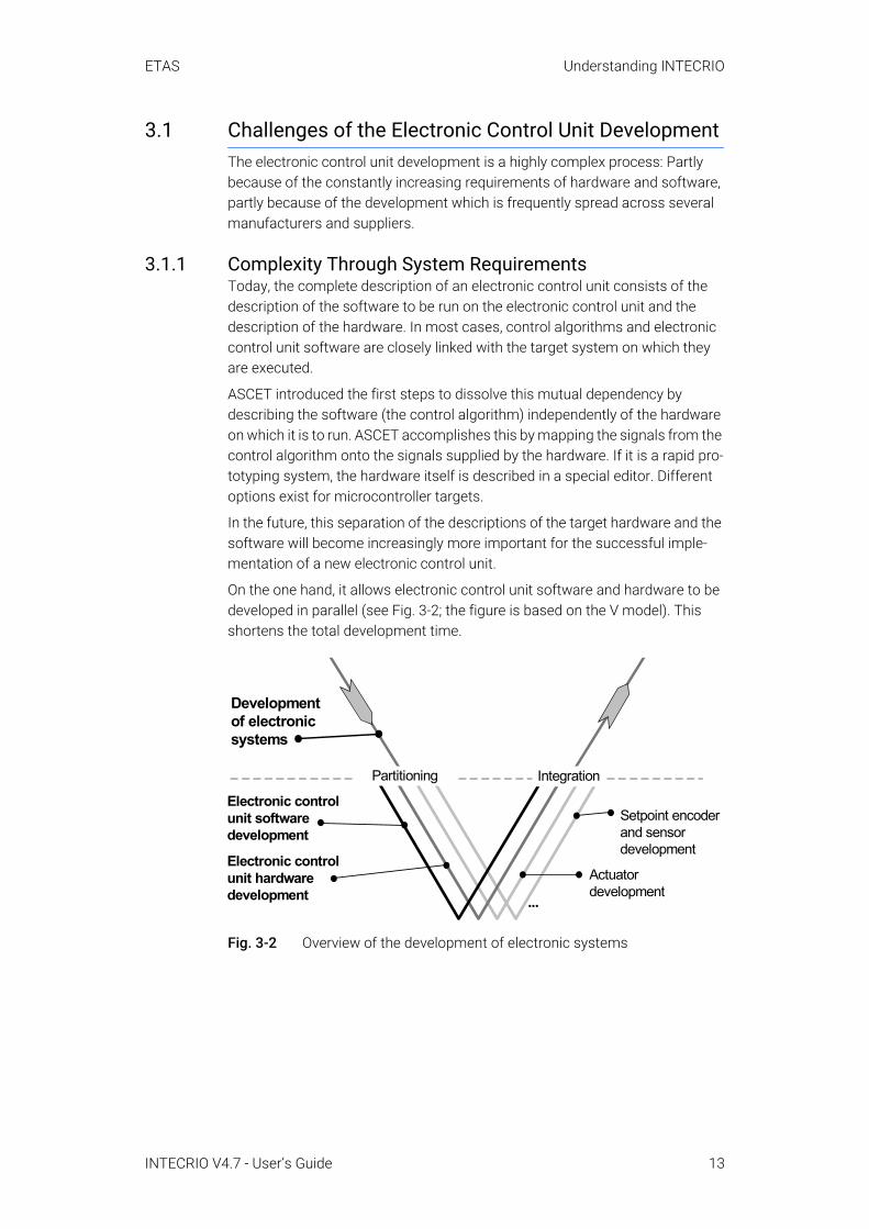
On the one hand, it allows electronic control unit software and hardware to be developed in parallel (see Fig. 3-2; the figure is based on the V model). This shortens the total development time.
Fig. 3-2 Overview of the development of electronic systems
Developmentof electronicsystems
Electronic controlunit softwaredevelopment
Setpoint encoderand sensordevelopment
Actuatordevelopment
...
Electronic controlunit hardwaredevelopment
Partitioning Integration
INTECRIO V4.7 - User’s Guide 13
ETAS Understanding INTECRIO
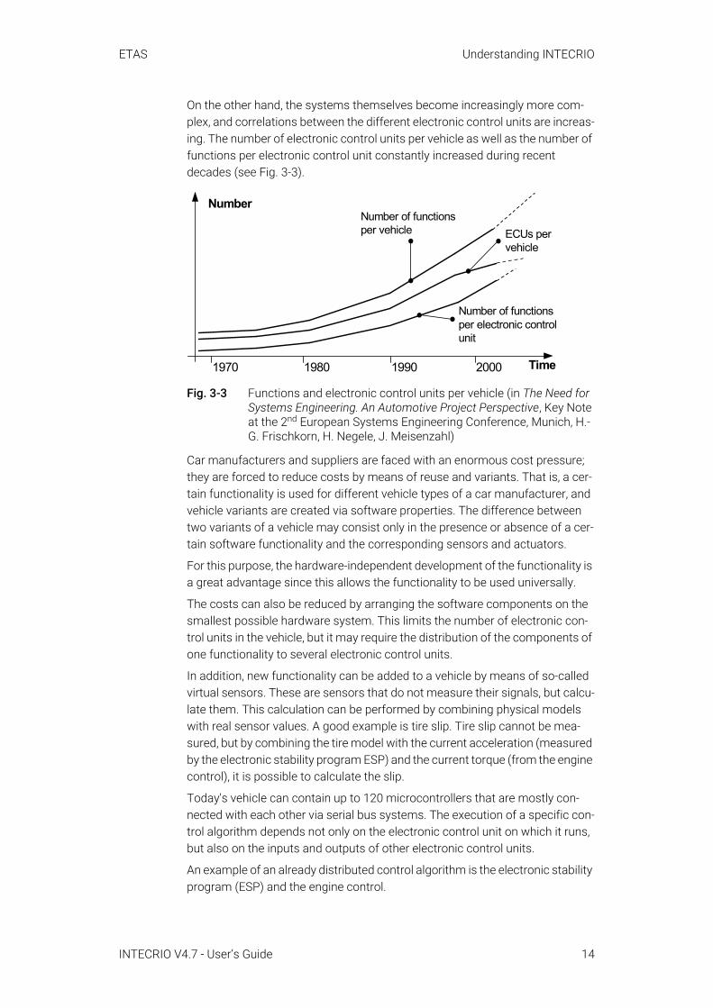
On the other hand, the systems themselves become increasingly more com-plex, and correlations between the different electronic control units are increas-ing. The number of electronic control units per vehicle as well as the number of functions per electronic control unit constantly increased during recent decades (see Fig. 3-3).
Fig. 3-3 Functions and electronic control units per vehicle (in The Need for Systems Engineering. An Automotive Project Perspective, Key Note at the 2nd European Systems Engineering Conference, Munich, H.-G. Frischkorn, H. Negele, J. Meisenzahl)
Car manufacturers and suppliers are faced with an enormous cost pressure; they are forced to reduce costs by means of reuse and variants. That is, a cer-tain functionality is used for different vehicle types of a car manufacturer, and vehicle variants are created via software properties. The difference between two variants of a vehicle may consist only in the presence or absence of a cer-tain software functionality and the corresponding sensors and actuators.
For this purpose, the hardware-independent development of the functionality is a great advantage since this allows the functionality to be used universally.
The costs can also be reduced by arranging the software components on the smallest possible hardware system. This limits the number of electronic con-trol units in the vehicle, but it may require the distribution of the components of one functionality to several electronic control units.
In addition, new functionality can be added to a vehicle by means of so-called virtual sensors. These are sensors that do not measure their signals, but calcu-late them. This calculation can be performed by combining physical models with real sensor values. A good example is tire slip. Tire slip cannot be mea-sured, but by combining the tire model with the current acceleration (measured by the electronic stability program ESP) and the current torque (from the engine control), it is possible to calculate the slip.
Today's vehicle can contain up to 120 microcontrollers that are mostly con-nected with each other via serial bus systems. The execution of a specific con-trol algorithm depends not only on the electronic control unit on which it runs, but also on the inputs and outputs of other electronic control units.
An example of an already distributed control algorithm is the electronic stability program (ESP) and the engine control.
ECUs pervehicle
Number of functionsper electronic controlunit
NumberNumber of functionsper vehicle
1970 1980 1990 2000 Time
INTECRIO V4.7 - User’s Guide 14

ETAS Understanding INTECRIO
As soon as a critical driving situation is discovered, the ESP system requests a reduction in engine torque from the engine control. This request is generally transferred via the CAN bus. As soon as the engine torque is reduced, the car can stabilize itself and the torque can subsequently be increased again. If the vehicle does not stabilize itself, the engine torque must be further reduced.
The following components are involved in the control algorithm: The ESP must detect the necessity for reducing the engine torque. It must send the CAN mes-sage and wait for a free position on the CAN bus. Depending on the load on the CAN bus and the configuration of the communication, this may take some time. Next, the engine control unit must process the request for a torque reduc-tion. The engine control unit also has other tasks (namely the engine control) that are very time-critical. As soon as it finds some time to reduce the torque, it will do so. The sum of all these waiting times provides an imperfect control behavior which the driver may even notice (which is extremely undesirable).
This example underscores the fact that the electronics in the vehicle is becom-ing more and more complex. On the other hand, the electronics plays an important role for the success of a vehicle since 90% of all innovations in today's vehicles are based on electronics. For this reason, car manufacturers and suppliers alike are very much interested in increasing the quality and func-tionality of their vehicles.
3.1.2 Complexity Through Distributed DevelopmentAn additional contribution to the complexity of the electronic control unit devel-opment consists of the fact that the development is often formed by a strong division of labor between car manufacturers and suppliers. While the user requirements to be considered on a function of the vehicle to be developed are generally defined by the car manufacturer, the implementation of the functions through electronic systems is often carried out by suppliers. However, the coor-dination and acceptance of the implemented functions in the vehicle is gener-ally the responsibility of the car manufacturer.
An indispensable prerequisite for a successful development with such a divi-sion of labor is a precise definition of the interfaces between car manufacturer and supplier. They can be clearly represented in the V model (Fig. 3-4). While the car manufacturer carries the responsibility for the vehicle–on the left as well as the right branch of the V model–the suppliers are frequently in charge of the component level, at times even for the first integration steps.
INTECRIO V4.7 - User’s Guide 15

ETAS Understanding INTECRIO
These interfaces can be defined differently from case to case, but they must be defined exactly and completely in any case.
Fig. 3-4 Responsibilities of car manufacturers and suppliers. The interfaces entered (dot-dash-lines) are examples.
The AUTOSAR partnership develops a standardization of basic system and interface functions. INTECRIO V4.7 supports AUTOSAR; see chapter 4 for more information.
3.1.3 Possible StepsOne could say now that the best way for a cost reduction consists of first defin-ing the functionality that a vehicle must have, and then to determine which hardware is required for the system to run.
However, this would mean to redevelop the complete vehicle functionality at once, which would involve significant effort and even risks. Therefore, it would be more obvious to first describe today's electronic system and to control the complexity it contains. INTECRIO was developed for this reason. As soon as it is under control, optimization is the next step.
Additional information can be found in
• J. Schäuffele, Dr. T. Zurawka: "Automotive Software Engineering – Prin-ciples, Processes, Methods, and Tools".
3.2 Description of Electronic SystemsA complete electronic control unit description requires a description of the hardware as well as the software. As mentioned above, today's software can no longer be viewed only as a collection of different software components that run on independent electronic control units. Frequently, a complete control algorithm is already distributed across several electronic control units and, therefore, must be viewed and described as a whole, without orientation to the special electronic control unit.
Vehicle development
Subsystem development Drive traindevelopment
Chassisdevelopment
Bodyworkdevelopment
Multimediadevelopment
Car manufacturer
Supplier
Car manufacturerSupplier
INTECRIO V4.7 - User’s Guide 16

ETAS Understanding INTECRIO
Since networks are not yet supported in INTECRIO V4.7, the focus of this sec-tion is on the description of an individual electronic control unit.
3.2.1 Design and Operating Method of Electronic SystemsDesign and operating method of the electronic systems of the vehicle are explained in detail using the electrohydraulic braking system as an example.
Fig. 3-5 Design of the electrohydraulic brake (in Konventionelle und elektronische Bremssysteme, Robert Bosch GmbH (ed.), Stuttgart, 2002)
Fig. 3-5 shows the design of the electrohydraulic braking system (Sensotronic Brake Control, SBC) from Bosch. The sensotronic brake control combines the functions of the power brake unit, anti-lock braking system (ABS) and ESP.
The mechanical activation of the brake pedal by the driver is sensed in the brake pedal unit and electrically transferred to the electronic control unit. This electronic control unit uses required values and different sensor signals, such as the steering angle signal or the wheel speed signals, to calculate output quantities which, in turn, are electrically transferred to the hydro unit where they are converted into controlled variables for the wheel brakes through pressure modulation. The handling of the vehicle, the so-called route (or controlled sys-tem) is influenced via the wheel brakes. For this reason, the wheel brakes are also referred to as actuators.
The electronic control unit can communicate with other electronic control units of the vehicle via a bus, such as CAN.
Vehicle
Environment
Driver
Othervehicles
Electroniccontrol units
Bus
Hydrounit
Brake pedal unit(setpoint encoder)
Wheelbrake(actuator)
Wheel brake(actuator)
Steeringanglesensor
Wheelspeedsensor
Tool(e.g. diagnostic tester)
INTECRIO V4.7 - User’s Guide 17
ETAS Understanding INTECRIO
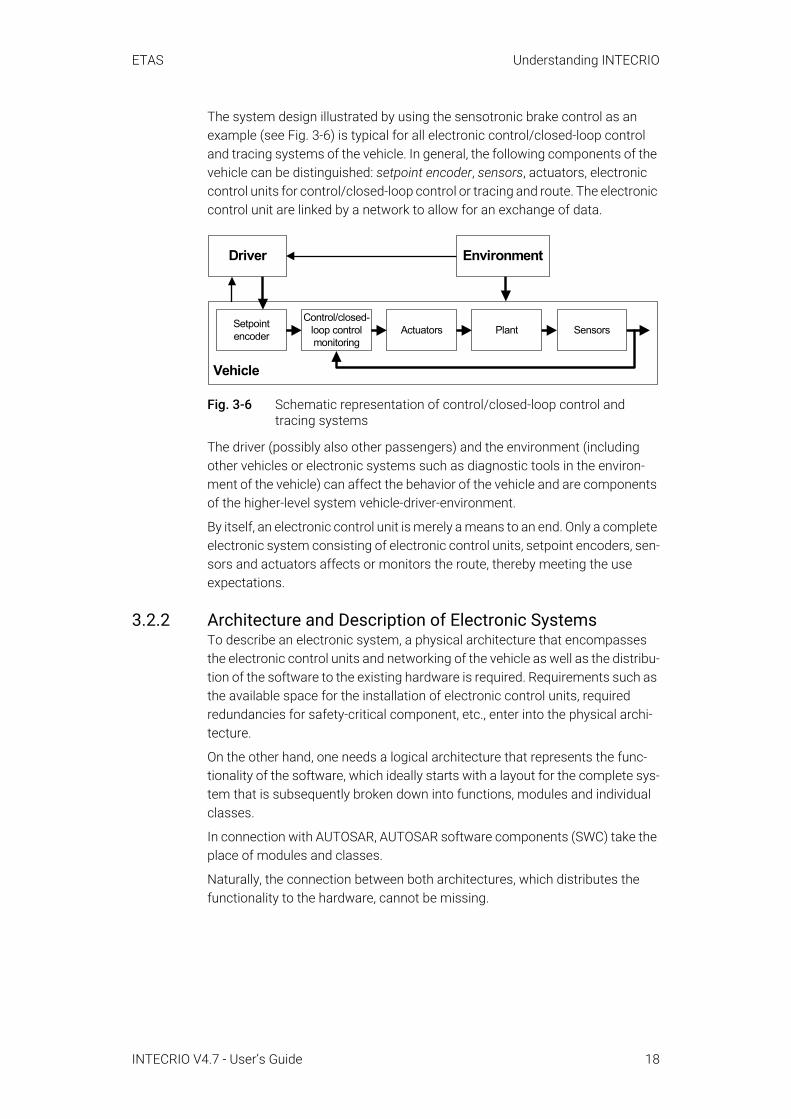
The system design illustrated by using the sensotronic brake control as an example (see Fig. 3-6) is typical for all electronic control/closed-loop control and tracing systems of the vehicle. In general, the following components of the vehicle can be distinguished: setpoint encoder, sensors, actuators, electronic control units for control/closed-loop control or tracing and route. The electronic control unit are linked by a network to allow for an exchange of data.
Fig. 3-6 Schematic representation of control/closed-loop control and tracing systems
The driver (possibly also other passengers) and the environment (including other vehicles or electronic systems such as diagnostic tools in the environ-ment of the vehicle) can affect the behavior of the vehicle and are components of the higher-level system vehicle-driver-environment.
By itself, an electronic control unit is merely a means to an end. Only a complete electronic system consisting of electronic control units, setpoint encoders, sen-sors and actuators affects or monitors the route, thereby meeting the use expectations.
3.2.2 Architecture and Description of Electronic SystemsTo describe an electronic system, a physical architecture that encompasses the electronic control units and networking of the vehicle as well as the distribu-tion of the software to the existing hardware is required. Requirements such as the available space for the installation of electronic control units, required redundancies for safety-critical component, etc., enter into the physical archi-tecture.
On the other hand, one needs a logical architecture that represents the func-tionality of the software, which ideally starts with a layout for the complete sys-tem that is subsequently broken down into functions, modules and individual classes.
In connection with AUTOSAR, AUTOSAR software components (SWC) take the place of modules and classes.
Naturally, the connection between both architectures, which distributes the functionality to the hardware, cannot be missing.
Vehicle
EnvironmentDriver
Actuators Plant SensorsSetpointencoder
Control/closed-loop controlmonitoring
INTECRIO V4.7 - User’s Guide 18
ETAS Understanding INTECRIO
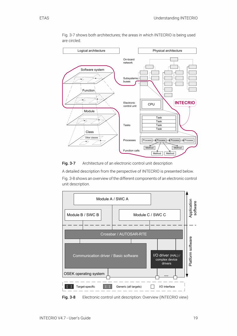
Fig. 3-7 shows both architectures; the areas in which INTECRIO is being used are circled.
Fig. 3-7 Architecture of an electronic control unit description
A detailed description from the perspective of INTECRIO is presented below.
Fig. 3-8 shows an overview of the different components of an electronic control unit description.
Fig. 3-8 Electronic control unit description: Overview (INTECRIO view)
On-boardnetwork
Tasks
Electroniccontrol unit
Subsystems,buses
Processes
Function calls
Logical architecture
Other classes
Software system
Function
Module
Class
INTECRIO
TaskTaskTaskTask
CPU
Method Method
MethodMethod
Physical architecture
Process ProcessProcessProcess
OSEK operating system
I/O driver (HAL) / complex device
drivers
Module B / SWC B
Module A / SWC A
Module C / SWC C Appl
icat
ion
softw
are
Plat
form
sof
twar
e
Crossbar / AUTOSAR-RTE
Communication driver / Basic software
....
[ ] Target-specific [ ] Generic (all targets) I/O interface
INTECRIO V4.7 - User’s Guide 19

ETAS Understanding INTECRIO
3.2.2.1 Application SoftwareThe application software (or functional software) contains the signal flow-driven control algorithm. This is a generic description that does not change its behavior (based on requirements and specifications). The software consists of individual modules or AUTOSAR software components and module/SWC groups or functions (see Fig. 3-9 and the left side of Fig. 3-7).
Fig. 3-9 Functional software: Details
The overview in Fig. 3-2 shows the development of the electronic control unit software as a single development phase; however, section 3.1.2, Fig. 3-4 already showed that this phase is divided again into other phases. This figure is still too rough, though; even in the development of a specific functionality, it is possible that the individual modules, SWC or functions are developed by differ-ent suppliers using different tools.
Modules and AUTOSAR software components are principally designed the same way from the INTECRIO perspective and feature the following interfaces:
• Signal sinks (inputs or clients and receivers),• Signal sources (outputs or server and sender),• Activation interfaces (processes or runnable entities (RE); graphically not
shown).
Fig. 3-10 Module/SWC: Schematic design (external view) and connection
Modules and AUTOSAR software components are also identical from an inter-nal design. In addition to the interfaces listed, the internal view contains the following components:
• Calculation algorithm or functionality,
Module/SWC A
Module/SWC B
Module/SWC C
BMT view
Signal sinks
Activation interface
Signal sour-ces
Data
Calculation algorithm
OSEK operating system
I/O driver (hardware abstraction
layer)
....
Module/SWC B
Module/SWC A
Module/SWC C
Crossbar / AUTOASR-RTE
Communication driver
Module 1... ...
Module 2... ...
Signal flowconnection
Sink 1Sink 2
Source 1Source 2
Sink 1Sink 2
Source 1Source 2
SWC A
Receiver SenderClient ServerMode
INTECRIO V4.7 - User’s Guide 20
ETAS Understanding INTECRIO
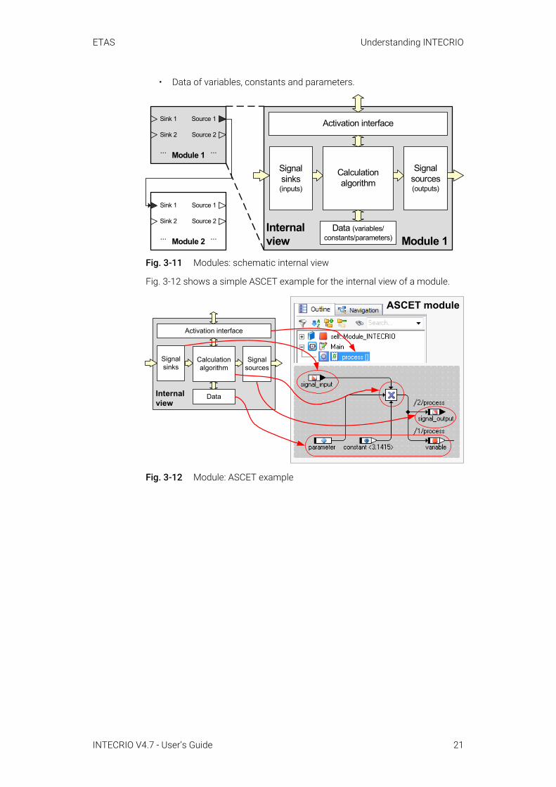
• Data of variables, constants and parameters.
Fig. 3-11 Modules: schematic internal view
Fig. 3-12 shows a simple ASCET example for the internal view of a module.
Fig. 3-12 Module: ASCET example
Module 1... ...
Sink 1 Source 1
Source 2Sink 2
Module 2... ...
Sink 1
Sink 2
Source 1
Source 2 Internalview Module 1
Signalsinks(inputs)
Activation interface
Signalsources(outputs)
Data (variables/constants/parameters)
Calculationalgorithm
Internalview
Signalsinks
Activation interface
Signalsources
Data
Calculationalgorithm
ASCET moduleASCET module
INTECRIO V4.7 - User’s Guide 21
ETAS Understanding INTECRIO
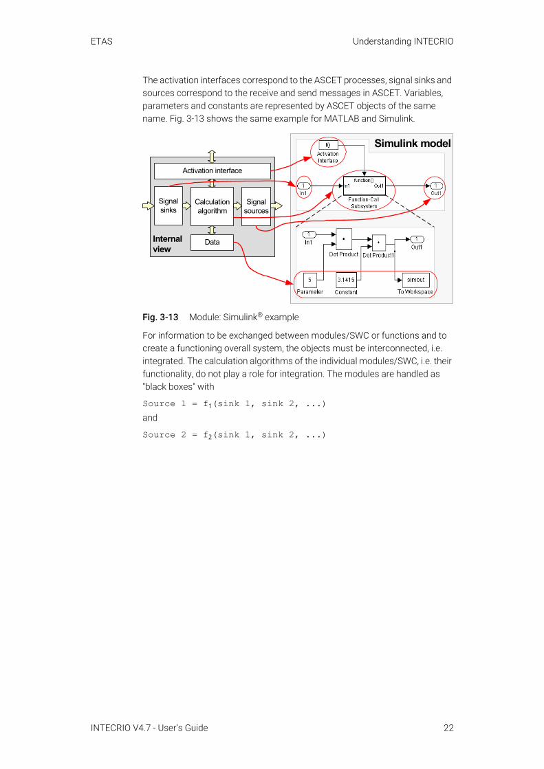
The activation interfaces correspond to the ASCET processes, signal sinks and sources correspond to the receive and send messages in ASCET. Variables, parameters and constants are represented by ASCET objects of the same name. Fig. 3-13 shows the same example for MATLAB and Simulink.
Fig. 3-13 Module: Simulink® example
For information to be exchanged between modules/SWC or functions and to create a functioning overall system, the objects must be interconnected, i.e. integrated. The calculation algorithms of the individual modules/SWC, i.e. their functionality, do not play a role for integration. The modules are handled as "black boxes" with
Source 1 = f1(sink 1, sink 2, ...)and
Source 2 = f2(sink 1, sink 2, ...)
Internalview
Signalsinks
Activation interface
Signalsources
Data
Calculationalgorithm
Simulink model
INTECRIO V4.7 - User’s Guide 22

ETAS Understanding INTECRIO
This integration is the responsibility of INTECRIO. To be able to fulfill this task, the model supplied by a BMT is dismantled for working with INTECRIO into description files for the interfaces and data as well as into C code (see Fig. 3-14). These files form a reusable software component; they can be pro-cessed by INTECRIO.
Fig. 3-14 Internal view and component view of a module (dashed: descriptions; solid: implementations)
3.2.2.2 Platform Software: Hardware SystemsOn the other side are the hardware systems that are affected by cost factors and the different variants of a vehicle. The hardware is a network of electronic control units that form a complete hardware topology. The latter must describe all aspects of the hardware system that is available to the software. The hard-ware system is also a generic system whose behavior or properties do not change.
With virtual prototyping, a model of driver, vehicle and environment is used instead of real hardware and environment.
3.2.2.3 Connecting Hardware and SoftwareFinally, both systems must be connected with each other. To build a prototype (or an actual vehicle project), the description of the software system must be linked with the description of the hardware system. This linking forms a con-crete application. Of course, this requires some "adhesive" to connect the generic software description and the generic hardware description.
INTECRIO is the tool that provides this "adhesive" in the form of a project configurator and connects the hardware description with the description of the application software. Here, the focus is on the hardware description – it is con-figured in INTECRIO while the components that form the application software are provided by special behavioral modeling tools.
Internalview
Signalsinks(inputs)
Activation interface
Signalsources(outputs)
Data (variables/constants/parameters)
Calculationalgorithm
Com
pone
nt
C code
Datadescription file(ASAM-2MC)
Interfacedescription file(SCOOP-IX)
INTECRIO V4.7 - User’s Guide 23
ETAS Understanding INTECRIO
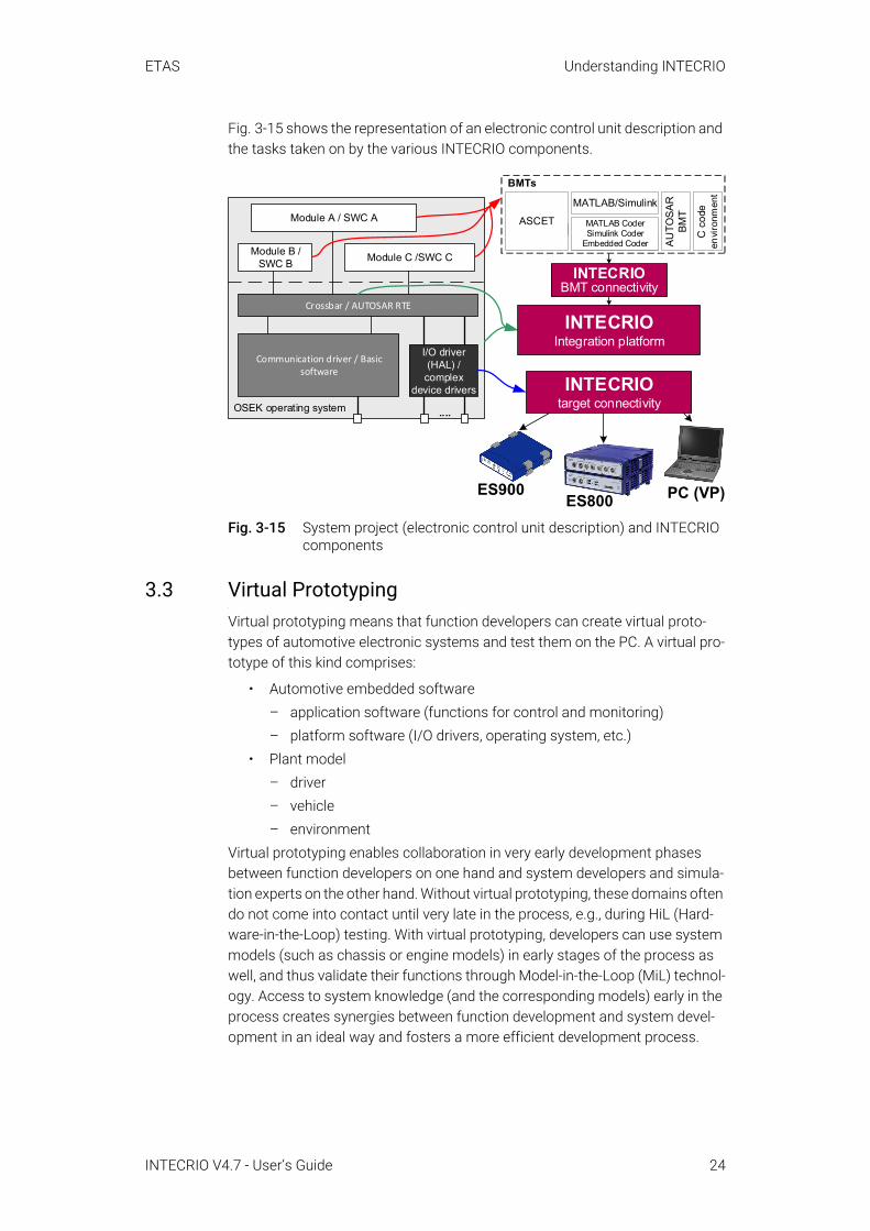
Fig. 3-15 shows the representation of an electronic control unit description and the tasks taken on by the various INTECRIO components.
Fig. 3-15 System project (electronic control unit description) and INTECRIO components
3.3 Virtual PrototypingVirtual prototyping means that function developers can create virtual proto-types of automotive electronic systems and test them on the PC. A virtual pro-totype of this kind comprises:
• Automotive embedded software– application software (functions for control and monitoring)– platform software (I/O drivers, operating system, etc.)
• Plant model– driver– vehicle– environment
Virtual prototyping enables collaboration in very early development phases between function developers on one hand and system developers and simula-tion experts on the other hand. Without virtual prototyping, these domains often do not come into contact until very late in the process, e.g., during HiL (Hard-ware-in-the-Loop) testing. With virtual prototyping, developers can use system models (such as chassis or engine models) in early stages of the process as well, and thus validate their functions through Model-in-the-Loop (MiL) technol-ogy. Access to system knowledge (and the corresponding models) early in the process creates synergies between function development and system devel-opment in an ideal way and fosters a more efficient development process.
OSEK operating system
I/O driver (HAL) / complex
device drivers
....
Module B /SWC B
Module A / SWC A
Module C /SWC C
Crossbar / AUTOSAR RTE
Communication driver / Basic software
INTECRIOIntegration platform
INTECRIOBMT connectivity
ASCET-RPASCET
BMTs
MATLAB Coder Simulink Coder
Embedded Coder
MATLAB/Simulink
C c
ode
envi
ronm
ent
AUTO
SAR
BM
T
INTECRIOtarget connectivity
ES900ES800 PC (VP)
INTECRIO V4.7 - User’s Guide 24

ETAS Understanding INTECRIO
3.3.1 Target-Close PrototypingIn INTECRIO, models can be created using a variety of different tools or a com-bination thereof (MATLAB and Simulink, ASCET, C code). With the PC connectivity provided by INTECRIO-VP, developers can now work within their familiar tool environment and execute their virtual prototype directly at their desks on a standard Windows PC. Already in the function design phase, developers can thus validate the functional architecture and verify the elec-tronic architecture against the plant model. Moreover, they can do all of this under target-close conditions. To put it plainly:
INTECRIO Integration Platform+ Function Model + Plant Model+ Standard PC+ RTA Virtual OSEK_____________________________________= Virtual Prototyping with INTECRIOBy supporting RTA-OSEK for PC, a complete OSEK operating system for the PC, INTECRIO-VP offers conditions that later exist on the vehicle ECU. These include task and process oriented scheduling and buffered message commu-nication between individual OS processes. At the same time, INTECRIO-VP takes advantage of the flexibility and short turn-around times of testing on the PC, which offers ample room for experimentation due to fewer constraints in terms of timing, memory consumption, etc. than exist on the target ECU.
3.3.2 Advantages of Virtual PrototypingVirtual prototyping offers new opportunities for early phases of vehicle develop-ment, such as pre-calibration in the office, detailed analysis of function behav-ior, and control over the execution speed of a prototype, as the following three examples illustrate.
A Saving time and money through pre-calibration
With virtual prototyping, developers can move some of the necessary development steps from the test bench to the lab or to their desks and validate, optimize, and pre-calibrate functions against a plant model right there. In addition, a virtual testing environment on the PC also offers developers the advantage of being able to minimize the execution time of experiments (given the computational power and the complexity of the model) and thus test a larger amount of functions or data variants in a shorter amount of time (Fig. 3-16 bottom).
B Detailed analysis using highly elaborate simulation models
The option of validating a new function based on elaborate plant simula-tions allows developers to conduct a detailed analysis of its behavior. This possibility is particularly valuable when an in-depth analysis is not possible in the real-world environment.
INTECRIO V4.7 - User’s Guide 25
ETAS Understanding INTECRIO
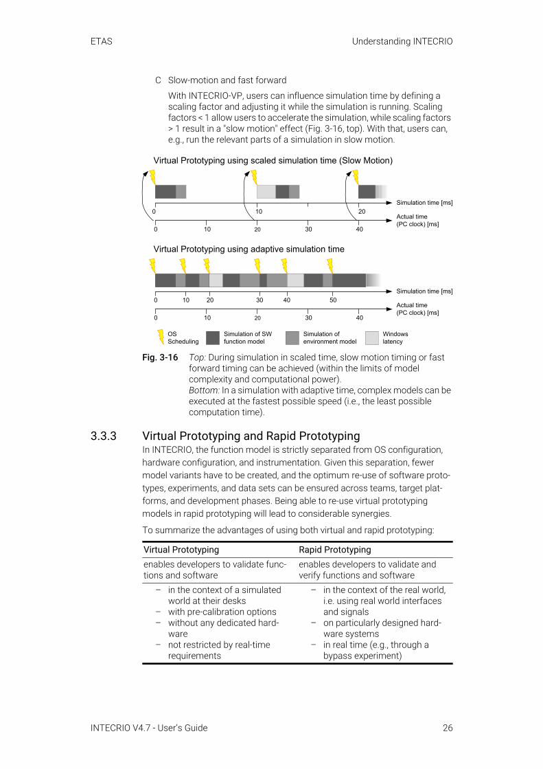
C Slow-motion and fast forward
With INTECRIO-VP, users can influence simulation time by defining a scaling factor and adjusting it while the simulation is running. Scaling factors < 1 allow users to accelerate the simulation, while scaling factors > 1 result in a "slow motion" effect (Fig. 3-16, top). With that, users can, e.g., run the relevant parts of a simulation in slow motion.
Fig. 3-16 Top: During simulation in scaled time, slow motion timing or fast forward timing can be achieved (within the limits of model complexity and computational power).Bottom: In a simulation with adaptive time, complex models can be executed at the fastest possible speed (i.e., the least possible computation time).
3.3.3 Virtual Prototyping and Rapid Prototyping In INTECRIO, the function model is strictly separated from OS configuration, hardware configuration, and instrumentation. Given this separation, fewer model variants have to be created, and the optimum re-use of software proto-types, experiments, and data sets can be ensured across teams, target plat-forms, and development phases. Being able to re-use virtual prototyping models in rapid prototyping will lead to considerable synergies.
To summarize the advantages of using both virtual and rapid prototyping:
Virtual Prototyping Rapid Prototypingenables developers to validate func-tions and software
enables developers to validate and verify functions and software
– in the context of a simulated world at their desks
– with pre-calibration options– without any dedicated hard-
ware – not restricted by real-time
requirements
– in the context of the real world, i.e. using real world interfaces and signals
– on particularly designed hard-ware systems
– in real time (e.g., through a bypass experiment)
OSScheduling
Simulation ofenvironment model
Simulation of SWfunction model
Windowslatency
0 10 20 30 40
0 10 20Simulation time [ms]
Virtual Prototyping using scaled simulation time (Slow Motion)
Actual time(PC clock) [ms]
Simulation time [ms]
Actual time(PC clock) [ms]
Virtual Prototyping using adaptive simulation time
0 10 20 30 40
0 10 20 30 40 50
INTECRIO V4.7 - User’s Guide 26
ETAS Understanding INTECRIO
Virtual prototyping thus complements the prototyping options available in INTECRIO to date. With INTECRIO-VP, vehicle developers are able to test new functions against plant simulations in early phases of development, which will contribute to a more efficient development process.
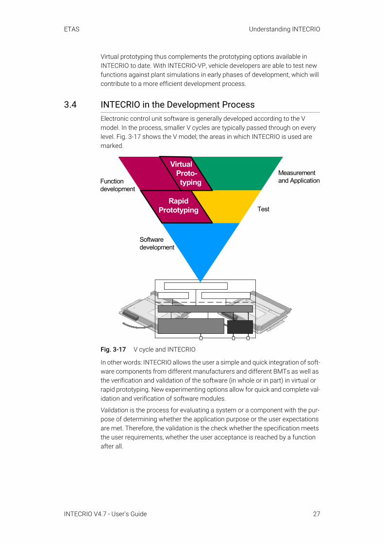
3.4 INTECRIO in the Development ProcessElectronic control unit software is generally developed according to the V model. In the process, smaller V cycles are typically passed through on every level. Fig. 3-17 shows the V model; the areas in which INTECRIO is used are marked.
Fig. 3-17 V cycle and INTECRIO
In other words: INTECRIO allows the user a simple and quick integration of soft-ware components from different manufacturers and different BMTs as well as the verification and validation of the software (in whole or in part) in virtual or rapid prototyping. New experimenting options allow for quick and complete val-idation and verification of software modules.
Validation is the process for evaluating a system or a component with the pur-pose of determining whether the application purpose or the user expectations are met. Therefore, the validation is the check whether the specification meets the user requirements, whether the user acceptance is reached by a function after all.
Functiondevelopment
Softwaredevelopment
Test
Measurementand Application
RapidPrototyping
Virtual Proto- typing
INTECRIO V4.7 - User’s Guide 27

ETAS Understanding INTECRIO
Verification is the process for evaluating a system or a component with the pur-pose of determining whether the results of a given development phase corre-spond to the specifications for this phase. Therefore, software verification is the check whether an implementation of the specification specified for the respective development step is sufficient.
A clear separation of validation and verification is often not possible when clas-sical development, integration and quality assurance methods for software are used. Therefore, a significant advantage of the use of INTECRIO as rapid proto-typing tool consists of the fact that it allows for an early and electronic control unit-independent function validation with an experimental system in the vehi-cle.
3.5 The INTECRIO Working EnvironmentThe design of INTECRIO is modular. The graphical framework forms the work-ing interface in which the various INTECRIO components are integrated.
Fig. 3-18 INTECRIO – Scheme of the interface
The graphical interface of INTECRIO is always designed in the same way. Below a menu bar and a toolbar, he interface of the currently used configurator (OS, project or hardware configurator) with the respective processing options is displayed in the top right field. The two lower fields are used for scripting (see online help for details) and as display for messages of the currently used con-figurator. The bottom pane contains various status information.
Toolbar Menu bar
File Edit View ...
Messages of the current component
WS browser(tree view ofworkspace) Display window for the
different components
Bottom pane
Scripting Window
INTECRIO Vx.y
Title Bar
INTECRIO V4.7 - User’s Guide 28

ETAS Understanding INTECRIO
The top left field, the WS browser, displays the current workspace in a tree structure. The workspace contains all the components of an electronic control unit description in four predetermined main folders for hardware systems, soft-ware systems, environment systems (virtual prototyping) and system proj-ects.The entire electronic control unit description is processed from here.
Fig. 3-19 Folder structure: workspace
Hardware systems: A hardware system is used for the configuration of the platform software. It contains the complete description of a hardware topology, consisting of the descriptions of the associated ECUs (rapid and virtual proto-typing targets) and – in later INTECRIO-versions – networks as well as the descriptions of the interfaces (bus systems) between the devices.
The components of the hardware systems are stored in the Hardware folder.
Fig. 3-20 Folder structure: hardware systems
Software systems and environment systems: A software system contains the application software, i.e. the generic parts of the control algorithm. For one thing, these are the modules and AUTOSAR software components (SWC) that contain the functionality. In addition, functions and connections between mod-ules, SWC and functions are part of the software system. In INTECRIO V4.7, the execution sequence is automatically determined based on the overall configu-ration.
Modules
Environment (contains environment software)
Functions
Environment Systems
Hardware Systems
Hardware
Systems (contains system projects)
Modules (contains modules and SWC)
Software
Functions
Software Systems
Workspace
Software
Hardware
ECU 1 (Experimental Target)Hardware Systems
Controller 1Hardware I/O
Environment
...
Systems
Workspace
INTECRIO V4.7 - User’s Guide 29

ETAS Understanding INTECRIO
An environment system contains the plant model for virtual prototyping, i.e. the model of driver, vehicle, and environment. An environment system is built like a software system.
The components of the software systems are stored in the Software folder and the corresponding subfolders. The components of the environment sys-tems are stored in the Environment folder and the corresponding subfolders.
Fig. 3-21 Folder structure: software systems and environment systems
System projects: A system project is a complete electronic control unit description. It combines a hardware system, a software system and an environ-ment system into an overall project. The mapping of the signals provided by the hardware onto the corresponding software signals and the configuration of the operating system (OS configuration) are also a part of the system project.
Environment
Systems
Software systemSoftware Systems
Function 2 (by reference)Module E (by reference)
(more software systems)(more functios/modules/SWC by reference)
Workspace
Software
Functions
Module A (by reference)Module C (by reference)
SWC B
Modules
Hardware
Function 1
(more functions)
Signal sourcesSignal sinks
Module A
(more modules/SWC)
Modules
Signal sources/sinksModule D
(more modules/SWC)
Environment
Workspace
Hardware
Software
Functions
Modules + SWC (by reference)Function 2
(more functions)
Systems
Environment systemEnvironment Systems
Functions/modules/SWC (by reference)(more environment systems)
INTECRIO V4.7 - User’s Guide 30
ETAS Understanding INTECRIO
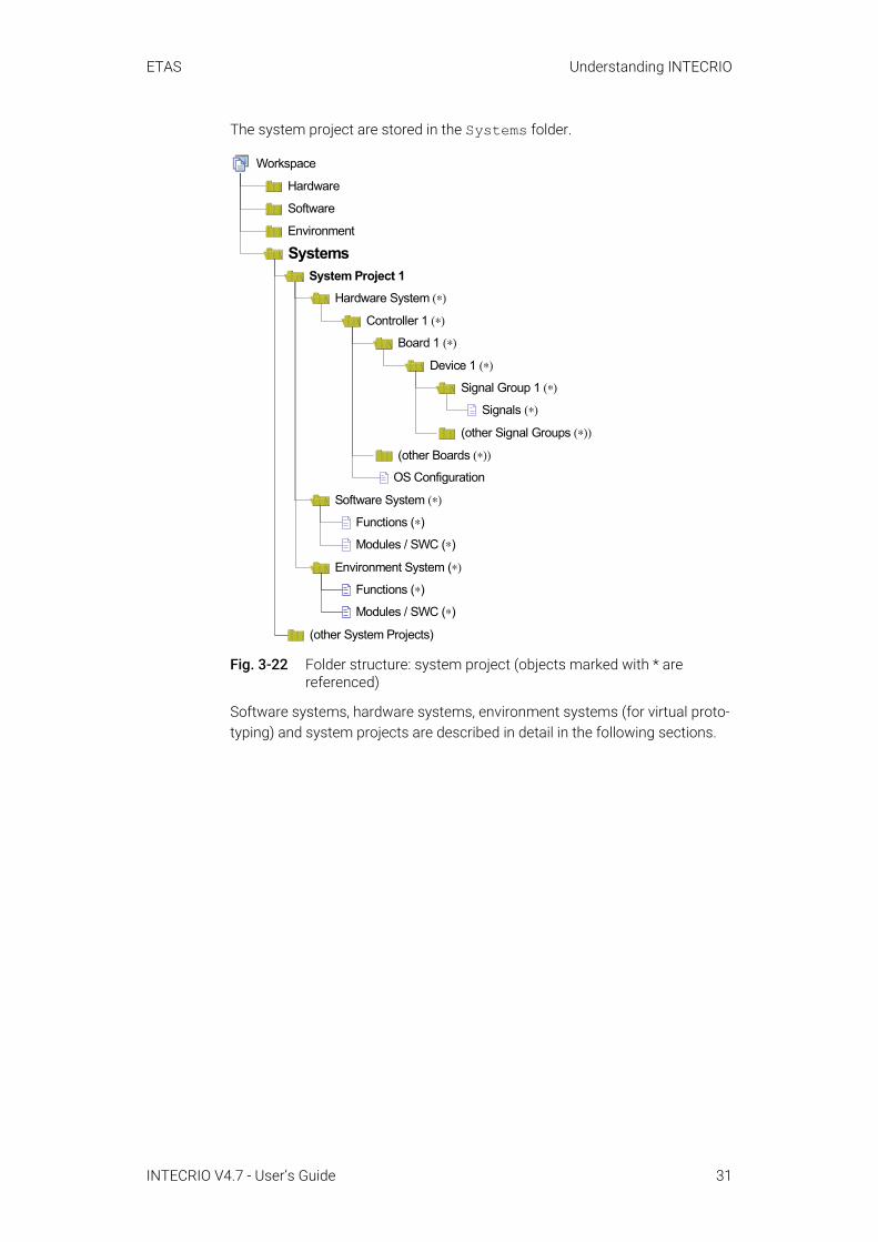
The system project are stored in the Systems folder.
Fig. 3-22 Folder structure: system project (objects marked with * are referenced)
Software systems, hardware systems, environment systems (for virtual proto-typing) and system projects are described in detail in the following sections.
Workspace
Software
Environment
Systems
Software System (∗)
Hardware System (∗)
System Project 1
Device 1 (∗)
Signals (∗)
Controller 1 (∗)
Board 1 (∗)
Signal Group 1 (∗)
(other Signal Groups (∗))
(other Boards (∗))
OS Configuration
Functions (∗)
Modules / SWC (∗)
(other System Projects)
Environment System (∗)
Functions (∗)
Modules / SWC (∗)
Hardware
INTECRIO V4.7 - User’s Guide 31

ETAS Understanding INTECRIO
3.5.1 Software SystemsThis section provides a detailed description of software systems. Fig. 3-23 shows the content of a software system. The lines symbolize inclusion rela-tionships; dashed objects in the background are optional (if available, they con-tain the same objects as the corresponding foreground object).
Fig. 3-23 The software system
3.5.1.1 Modules and AUTOSAR Software ComponentsThe modules and AUTOSAR software components (SWC) in INTECRIO contain the descriptions of the software modules that were imported in the system.
These can be user-defined ASCET modules, Simulink models or AUTOSAR software components, but also test functions or complex stimulus generators in C code or plant models (for "software in the loop" applications). The descrip-tions are based on SCOOP-IX descriptions (see chapter 6 "SCOOP and SCOOP-IX") or XML for AUTOSAR software components.
The schematic design of a module and SWC is represented in Fig. 3-10 on page 20. INTECRIO only knows the signal sources and sinks (inputs and outputs) as well as the activation interfaces (processes, or runnable entities for SWC) of the user-defined modules and SWC (interface description file in Fig. 3-14). The functionality of the software modules and SWC that was cre-ated with different BMTs is not of importance here.
In INTECRIO, hardware I/O ports are also considered as modules with signal sources and sinks.
The signal mapping, i.e. the connections between the corresponding inputs and outputs that are required for information exchange, must be performed explic-itly. There are no implicit connections, such as via same name.
ModulesModule / SWC
Inputsignals
Outputsignals
Processes /RE
Signal mapping
Software System
Function (optional)
INTECRIO V4.7 - User’s Guide 32
ETAS Understanding INTECRIO
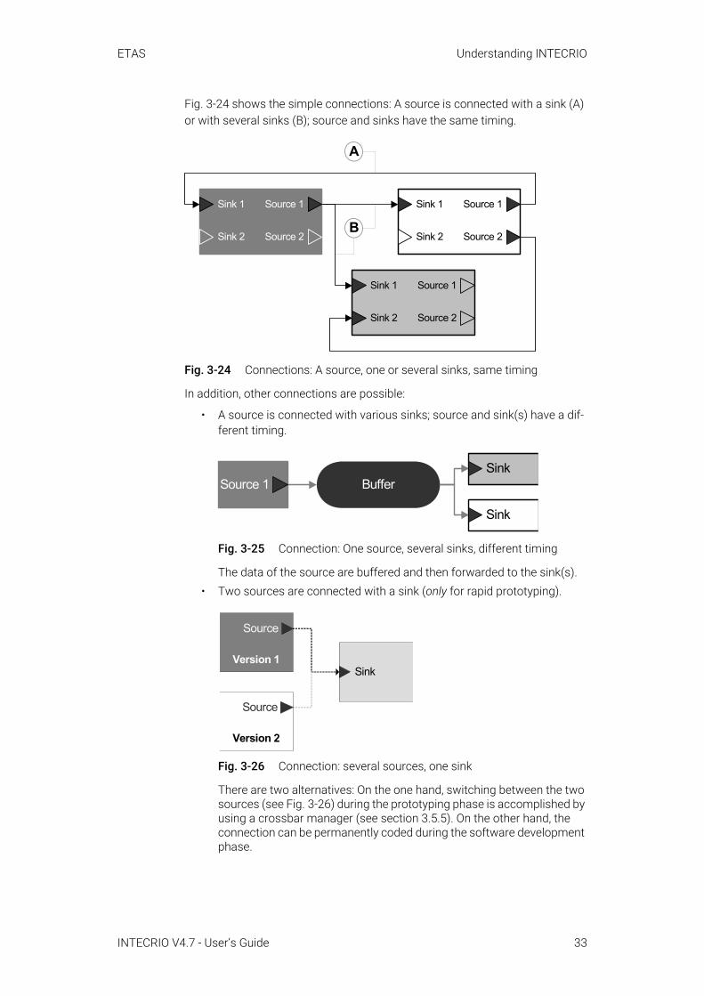
Fig. 3-24 shows the simple connections: A source is connected with a sink (A) or with several sinks (B); source and sinks have the same timing.
Fig. 3-24 Connections: A source, one or several sinks, same timing
In addition, other connections are possible:
• A source is connected with various sinks; source and sink(s) have a dif-ferent timing.
Fig. 3-25 Connection: One source, several sinks, different timing
The data of the source are buffered and then forwarded to the sink(s).• Two sources are connected with a sink (only for rapid prototyping).
Fig. 3-26 Connection: several sources, one sink
There are two alternatives: On the one hand, switching between the two sources (see Fig. 3-26) during the prototyping phase is accomplished by using a crossbar manager (see section 3.5.5). On the other hand, the connection can be permanently coded during the software development phase.
BSink 1
Sink 2
Source 1
Source 2
Sink 1
Sink 2
Source 1
Source 2
Sink 1
Sink 2
Source 1
Source 2
A
BufferSink
Sink
Source 1
Sink
Version 2
Source
Version 1
Source
INTECRIO V4.7 - User’s Guide 33

ETAS Understanding INTECRIO
3.5.1.2 FunctionsModules and SWC can be inserted in a software system either directly or – to provide a better overview or for a simple reuse – grouped in functions. These functions are classification objects without separate functionality (similar to the hierarchies in ASCET block diagrams).
A function consists of the following components:
• One or several modules or SWC,• Connections between inputs and outputs of the contained modules or
SWC,• The function interface (inputs, outputs and activation interfaces).
The inputs and outputs of a function cannot have their own data or implemen-tations. Outputs can be connected with one or several sinks of the modules/functions contained in the function, inputs with exactly one source of a mod-ule/function. With SWC, the output type determines whether the output can be connected to one or more inputs (see “Ports and Interfaces” on page 48).
It is also possible to automatically create the inputs and outputs of the func-tion. However, only the module/SWC inputs that are not yet connected can be taken into account. Outputs take into account either all sources of the mod-ules/SWC contained in the function or only those that are not yet connected.
Fig. 3-27 Example for a function
Modules cannot be instantiated in INTECRIO. If a module is inserted into a function more than once (either directly or as part of an inserted function), an error message is issued during code generation.
Function
SinkSource
Module 1Sink
Source
Module 2
ReceiverSWC C
ReceiverSender
INTECRIO V4.7 - User’s Guide 34
ETAS Understanding INTECRIO
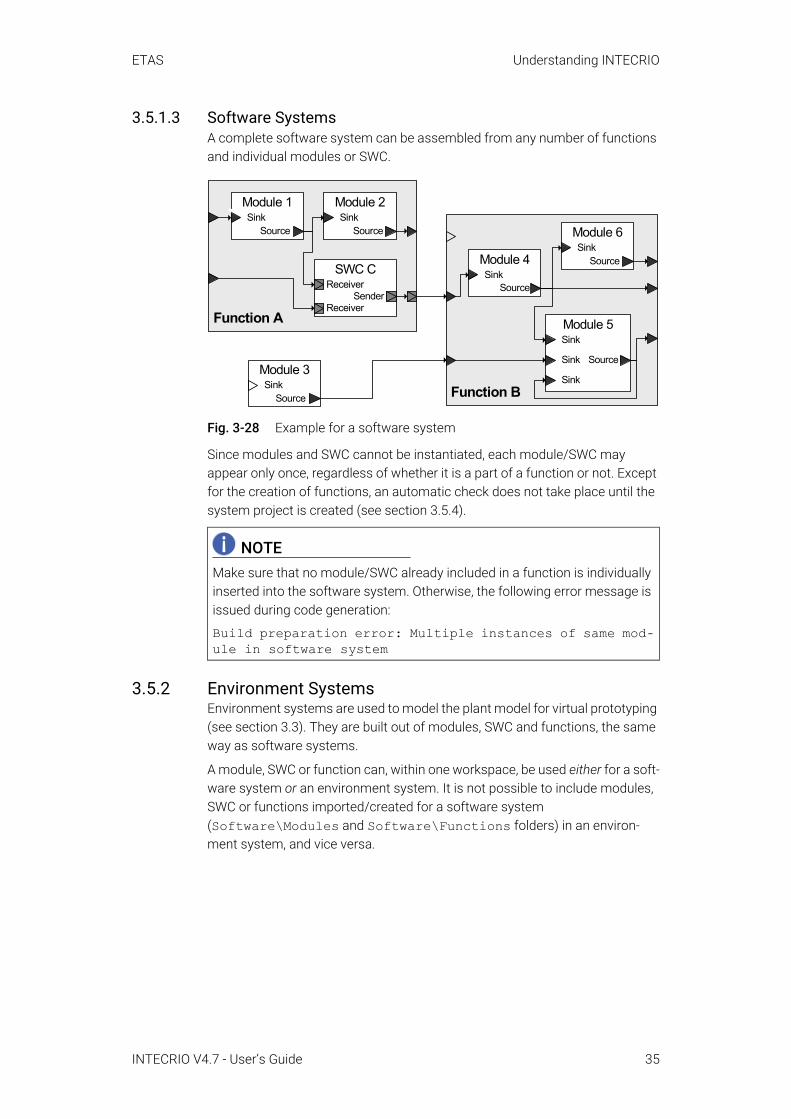
3.5.1.3 Software SystemsA complete software system can be assembled from any number of functions and individual modules or SWC.
Fig. 3-28 Example for a software system
Since modules and SWC cannot be instantiated, each module/SWC may appear only once, regardless of whether it is a part of a function or not. Except for the creation of functions, an automatic check does not take place until the system project is created (see section 3.5.4).
3.5.2 Environment SystemsEnvironment systems are used to model the plant model for virtual prototyping (see section 3.3). They are built out of modules, SWC and functions, the same way as software systems.
A module, SWC or function can, within one workspace, be used either for a soft-ware system or an environment system. It is not possible to include modules, SWC or functions imported/created for a software system (Software\Modules and Software\Functions folders) in an environ-ment system, and vice versa.
NOTEMake sure that no module/SWC already included in a function is individually inserted into the software system. Otherwise, the following error message is issued during code generation:
Build preparation error: Multiple instances of same mod-ule in software system
Function A
SinkSource
Module 1Sink
Source
Module 2
SinkSource
Module 3
Function B
SinkSource
Module 6
SinkSource
Module 4
Sink
Source
Module 5
Sink
Sink
ReceiverSWC C
ReceiverSender
INTECRIO V4.7 - User’s Guide 35

ETAS Understanding INTECRIO
3.5.3 Hardware SystemsFig. 3-29 shows the content of a hardware system (the lines symbolize inclu-sion relationships). In the framework of the hardware system, the existing hard-ware and the interfaces between the individual units (e.g. ETK, CAN) are described.
Fig. 3-29 The hardware system.
The ECU description is the description of an individual controller hardware that is usually installed inside a housing. (Despite different boards or interfaces, the experimental targets are considered electronic control units.)
This includes descriptions of all processors of the electronic control unit and the connections between the processors.
The CPU description is the description of an individual processor with all the relevant details. This includes
• Characteristics of the processor (type, brand, etc.),• Processor speed,• Memory layout,• Additional processor-specific configurations.
The I/O interface describes the interface between the input/output signals and the processor.
The input and output signals are linked with a specific processor. They are used to configure the inputs and outputs of the hardware (sensors and actuators) and to establish the connection to the corresponding processor signals.
3.5.4 System ProjectsThe system project combines a hardware system, a software system and an environment system (optional; for virtual prototyping) into an overall project. A check is performed whether each module occurs only once in the overall proj-ect; if a module occurs multiple times, an error message is issued.
ECU description
CPU description
I/O interface
Output signals
Hardware System
Input signals
INTECRIO V4.7 - User’s Guide 36
ETAS Understanding INTECRIO
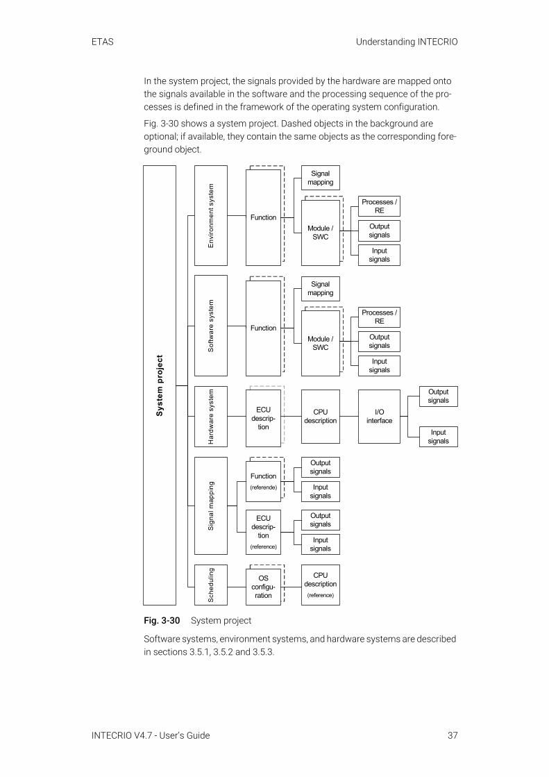
In the system project, the signals provided by the hardware are mapped onto the signals available in the software and the processing sequence of the pro-cesses is defined in the framework of the operating system configuration.
Fig. 3-30 shows a system project. Dashed objects in the background are optional; if available, they contain the same objects as the corresponding fore-ground object.
Fig. 3-30 System project
Software systems, environment systems, and hardware systems are described in sections 3.5.1, 3.5.2 and 3.5.3.
Syst
em p
roje
ct
Sch
edul
ing
OSconfigu-ration
CPUdescription
sd
(reference)
Sig
nal m
appi
ng
Functionsd
(referende) Inputsignals
Outputsignals
Inputsignals
Outputsignals
ECUdescrip-
tionsd
(reference)
Env
ironm
ent s
yste
mFunction
Module /SWC
Signalmapping
Inputsignals
Outputsignals
Processes /RE
Har
dwar
e sy
stem
ECUdescrip-
tion
CPUdescription
I/Ointerface
Inputsignals
Outputsignals
Sof
twar
e sy
stem
FunctionModule /
SWC
Signalmapping
Inputsignals
Outputsignals
Processes /RE
INTECRIO V4.7 - User’s Guide 37
ETAS Understanding INTECRIO
The signal mapping references the functions/modules/SWC of the software or environment and the ECU description with the respective inputs and outputs. The mapping is performed here. Since functions/modules/SWC and ECU description are referenced, changes to the software or hardware system imme-diately impact the signal mapping.
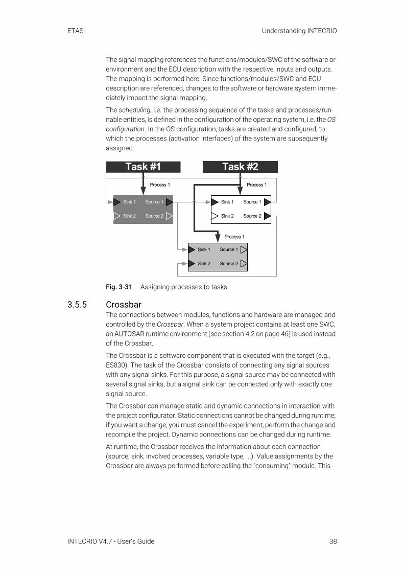
The scheduling, i.e. the processing sequence of the tasks and processes/run-nable entities, is defined in the configuration of the operating system, i.e. the OS configuration. In the OS configuration, tasks are created and configured, to which the processes (activation interfaces) of the system are subsequently assigned.
Fig. 3-31 Assigning processes to tasks
3.5.5 CrossbarThe connections between modules, functions and hardware are managed and controlled by the Crossbar. When a system project contains at least one SWC, an AUTOSAR runtime environment (see section 4.2 on page 46) is used instead of the Crossbar.
The Crossbar is a software component that is executed with the target (e.g., ES830). The task of the Crossbar consists of connecting any signal sources with any signal sinks. For this purpose, a signal source may be connected with several signal sinks, but a signal sink can be connected only with exactly one signal source.
The Crossbar can manage static and dynamic connections in interaction with the project configurator. Static connections cannot be changed during runtime; if you want a change, you must cancel the experiment, perform the change and recompile the project. Dynamic connections can be changed during runtime.
At runtime, the Crossbar receives the information about each connection (source, sink, involved processes, variable type, ...). Value assignments by the Crossbar are always performed before calling the "consuming" module. This
Sink 1
Sink 2
Source 1
Source 2
Sink 1
Sink 2
Source 1
Source 2
Sink 1
Sink 2
Source 1
Source 2
Process 1 Process 1
Task #1 Task #2
Process 1
INTECRIO V4.7 - User’s Guide 38

ETAS Understanding INTECRIO
allows the Crossbar to trigger the necessary actions at runtime. The result are connections between signal sources and sinks that are represented as grey cir-cles in Fig. 3-32.
Fig. 3-32 Crossbar – Overview
The patented Crossbar guarantees real-time security for the modules through carefully arranged copy actions. Required requantizations and data type con-versions are automatically performed.
A simple assignment serves as an example: sink 1 = source 0If the two sides of the assignment are quantized differently, the value of source 0 is requantized and then assigned to sink 1. If both sides feature different data types, source 0 is converted to the data type of sink 1.
Source 0
Source 1
Source 2
Source n
Sink 0
Sink 1
Sink 2
Sink m
-1
Sink m
Crossbar
Con
figur
atio
nin
form
atio
n
Schedulinginformation
INTECRIO V4.7 - User’s Guide 39

ETAS Understanding INTECRIO
3.6 Experimenting with INTECRIOThe executable prototype is created from the system project by using the proj-ect integrator (see section 5.9 "The Project Integrator"). Such a prototype shows the software functions in practical use – entirely with different goal directions and in a different appropriation.
Fig. 3-33 Prototype for rapid or virtual prototyping experiment
By using the prototype, a rapid prototyping hardware and an experiment envi-ronment (e.g., the ETAS Experiment Environment), the experiment can be per-formed under real-time conditions (also automatically if needed). This experiment fulfills the following purposes:
• Validation of the control algorithm (in whole or in part)• Verification of the software implementation• Verification of the implementation information of the model magnitudes
In the experiment, values can be measured and calibrated in different measur-ing and calibration windows. The configuration of the measuring and calibra-tion windows can be carried out either before or during the experiment. In a virtual prototyping experiment, the simulation speed can be adjusted at run-time, too.
Prototype of a control algorithm
Control algorithmSoftware system
Source 1
Source 2
Sink 1
Sink 2
Source 1
Source 2
Sink 1
Sink 2
Source 1
Source 2
Sink 1
Sink 2
Prototyping hardware system
External interfaces, e.g. CAN-DB
PC (VP)
ES900ES800
INTECRIO V4.7 - User’s Guide 40
ETAS Understanding INTECRIO
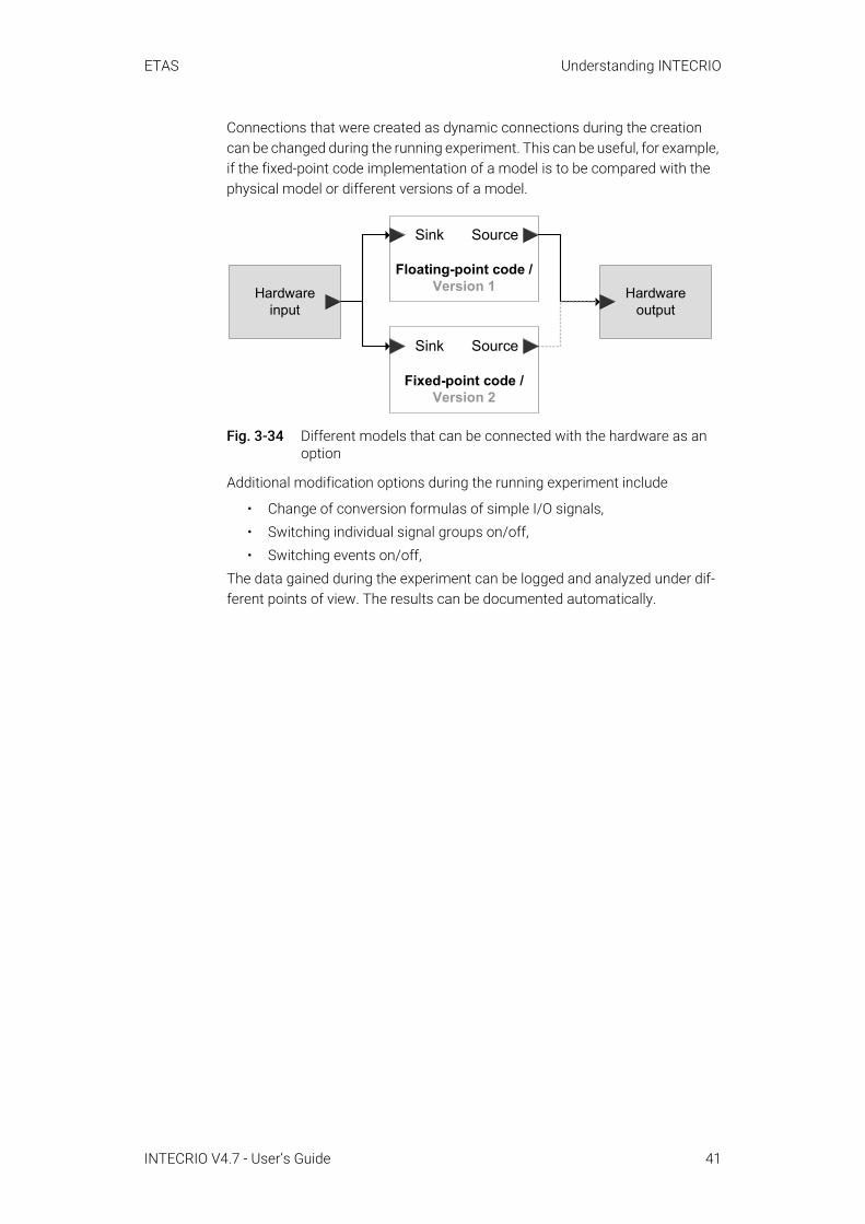
Connections that were created as dynamic connections during the creation can be changed during the running experiment. This can be useful, for example, if the fixed-point code implementation of a model is to be compared with the physical model or different versions of a model.
Fig. 3-34 Different models that can be connected with the hardware as an option
Additional modification options during the running experiment include
• Change of conversion formulas of simple I/O signals,• Switching individual signal groups on/off,• Switching events on/off,
The data gained during the experiment can be logged and analyzed under dif-ferent points of view. The results can be documented automatically.
Hardwareoutput
Hardwareinput
Fixed-point code / Version 2
Sink Source
Floating-point code / Version 1
Sink Source
INTECRIO V4.7 - User’s Guide 41

ETAS INTECRIO and AUTOSAR
4 INTECRIO and AUTOSARThis chapter describes how INTECRIO supports AUTOSAR. Section 4.1 over-views the purpose of AUTOSAR, section 4.2 describes the AUTOSAR runtime environment (RTE), section 4.3 lists the AUTOSAR elements supported by INTECRIO.
This chapter contains no detailed introduction to AUTOSAR; corresponding documents can be found at the AUTOSAR website: http://www.autosar.org/
4.1 OverviewToday, special effort is needed when integrating software components from different suppliers in a vehicle project comprising networks, electronic control units (ECUs), and dissimilar software architectures. While clearly limiting the reusability of automotive embedded software in different projects, this effort also calls for extra work in order to provide the required fully functional, tested, and qualified software.
By standardizing, inter alia, basic system functions and functional interfaces, the AUTOSAR partnership aims to simplify the joint development of software for automotive electronics, reduce its costs and time-to-market, enhance its quality, and provide mechanisms required for the design of safety relevant sys-tems.
To reach these goals, AUTOSAR defines an architecture for automotive embed-ded software. It provides for the easy reuse, exchange, scaling, and integration of those ECU-independent software components (SWCs) that implement the functions of the respective application.
The abstraction of the SWC environment is called the virtual function bus (VFB). In each real AUTOSAR ECU, the VFB is mapped by a specific, ECU-dependent implementation of the platform software. The AUTOSAR platform software is split into two major areas of functionality: the runtime environment (RTE) and the basic software (BSW). The BSW provides communications, I/O, and other functionality that all software components are likely to require, e.g., diagnostics and error reporting, or non-volatile memory management.
INTECRIO V4.7 - User’s Guide 42
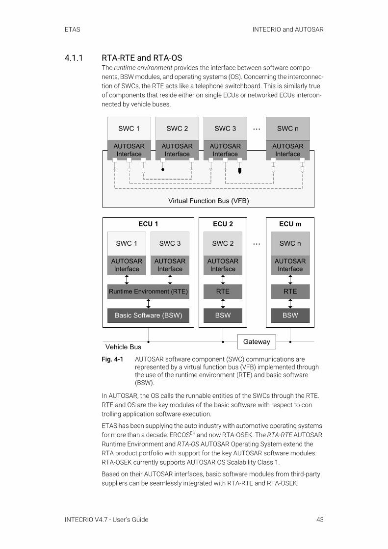
ETAS INTECRIO and AUTOSAR
4.1.1 RTA-RTE and RTA-OS The runtime environment provides the interface between software compo-nents, BSW modules, and operating systems (OS). Concerning the interconnec-tion of SWCs, the RTE acts like a telephone switchboard. This is similarly true of components that reside either on single ECUs or networked ECUs intercon-nected by vehicle buses.
Fig. 4-1 AUTOSAR software component (SWC) communications are represented by a virtual function bus (VFB) implemented through the use of the runtime environment (RTE) and basic software (BSW).
In AUTOSAR, the OS calls the runnable entities of the SWCs through the RTE. RTE and OS are the key modules of the basic software with respect to con-trolling application software execution.
ETAS has been supplying the auto industry with automotive operating systems for more than a decade: ERCOSEK and now RTA-OSEK. The RTA-RTE AUTOSAR Runtime Environment and RTA-OS AUTOSAR Operating System extend the RTA product portfolio with support for the key AUTOSAR software modules. RTA-OSEK currently supports AUTOSAR OS Scalability Class 1.
Based on their AUTOSAR interfaces, basic software modules from third-party suppliers can be seamlessly integrated with RTA-RTE and RTA-OSEK.
Virtual Function Bus (VFB)
...SWC 3
AUTOSARInterface
SWC 2
AUTOSARInterface
SWC n
AUTOSARInterface
SWC 1
AUTOSARInterface
SWC 1
AUTOSARInterface
SWC 3
AUTOSARInterface
ECU 1
Runtime Environment (RTE)
Basic Software (BSW)
SWC 2
AUTOSARInterface
ECU 2
RTE
BSW
... SWC n
AUTOSARInterface
ECU m
RTE
BSW
GatewayVehicle Bus
INTECRIO V4.7 - User’s Guide 43

ETAS INTECRIO and AUTOSAR
4.1.2 Creating AUTOSAR Software Components (outside INTEC-RIO) INTECRIO is not intended for the creation of AUTOSAR software components. ASCET, however, can be used to define and implement the behavior of AUTO-SAR-compliant vehicle functions. If necessary, an AUTOSAR authoring tool can provide initial descriptions of the system architecture and AUTOSAR interfaces,
Existing ASCET models can be easily adapted to AUTOSAR because many AUTOSAR concepts can be mapped to interface specifications in ASCET in a similar form. On the whole, it suffices to rework the interface of the respective application to make it AUTOSAR-compliant. As shown in practical demonstra-tions of adapting older models, the expenditure in terms of time is relatively minor, even with the ASCET version in current use.
Different ASCET versions support different AUTOSAR releases for the creation of AUTOSAR SWC descriptions and the generation of AUTOSAR-compliant SWC production code. See the ASCET documentation for details on the sup-ported AUTOSAR versions.
4.1.3 Validating Software ComponentsThe virtual function bus concept of AUTOSAR opens the road to virtual integra-tion. Because the virtual function bus blurs the ECU borders, software compo-nents of different functions can be integrated in the design phase prior to having completed the final mapping to individual ECUs. This means that the interaction of software components integrated by an RTE can be easily tested on a PC running an AUTOSAR OS.
INTECRIO V4.7 - User’s Guide 44

ETAS INTECRIO and AUTOSAR
INTECRIO provides a powerful environment for prototyping and validating automotive electronic systems. Version V4.7 enables the integration of AUTO-SAR SWCs with legacy function modules (Fig. 4-2). INTECRIO thus provides for the reuse of existing models and C code during the migration of ECU software to AUTOSAR architectures.
Fig. 4-2 Integration (left) of software modules for virtual prototyping (middle) or rapid prototyping (right) with the AUTOSAR RTE.AUTOSAR SWC can be combined with legacy functions (B) or tested as a pure AUTOSAR system (C). By using plant models, Model-in-the-Loop experiments are realized on the PC.
INTECRIO
RTA
-OS
EK
Crossbar RTE
ASCETModel
SimulinkModel
C CodeModule
...
RTA
-OS
EK
AUTOSAR RTE
ASCETModel
SimulinkModel
SWC
AUTOSARInterface
...
RTA
-OS
EK
AUTOSAR RTE
SWC n
AUTOSARInterface
...SWC 2
AUTOSARInterface
SWC 1
AUTOSARInterface
Step 1:Integration of software components
Step 3:Rapid prototyping in real-world environment
Step 2:Virtual prototyping on the PC
INTECRIO
RTA-TRACE
ECU
RapidPrototypingModule
Vehicle Bus
Bypass
INTECRIO
RTA-TRACE
...
Function prototype
...P
lant model
A
B
C
INTECRIO V4.7 - User’s Guide 45
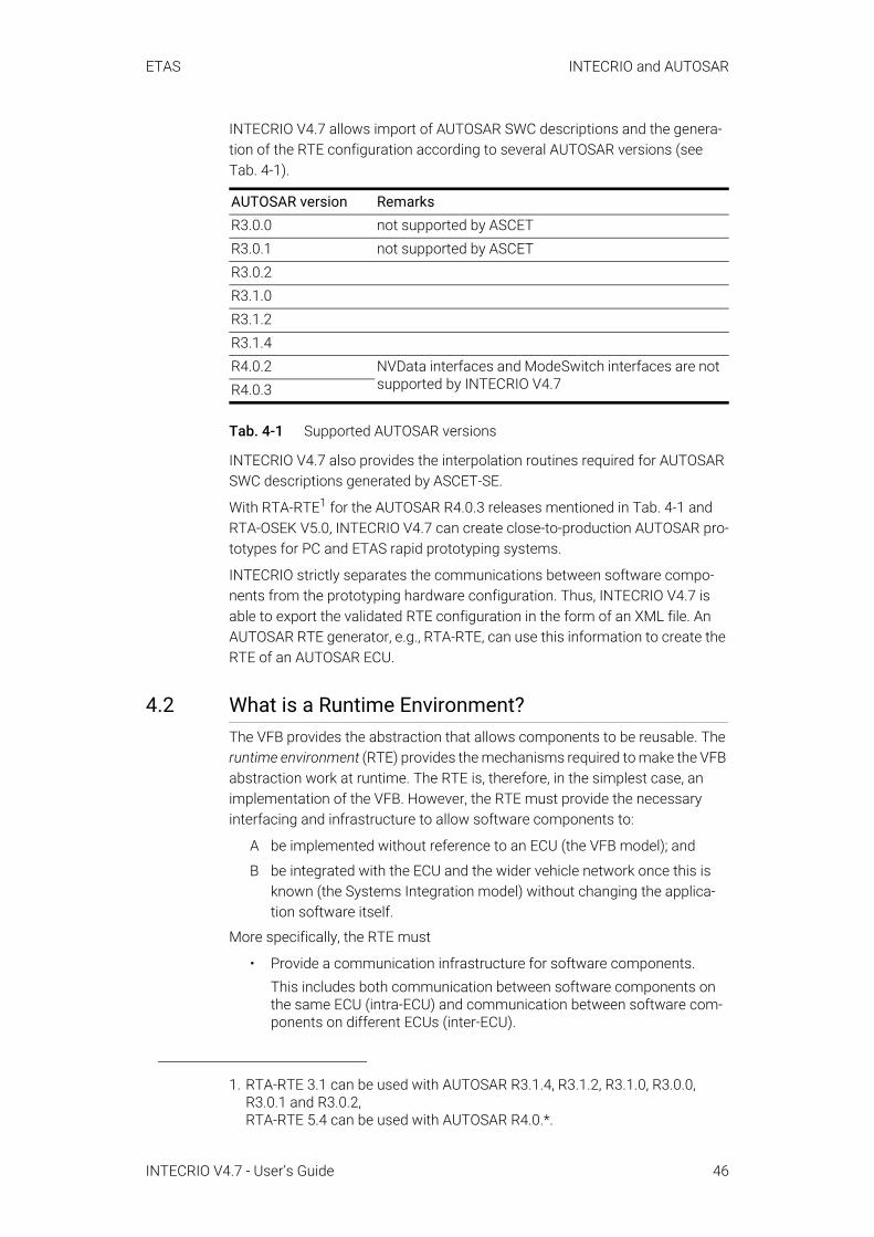
ETAS INTECRIO and AUTOSAR
INTECRIO V4.7 allows import of AUTOSAR SWC descriptions and the genera-tion of the RTE configuration according to several AUTOSAR versions (see Tab. 4-1).
Tab. 4-1 Supported AUTOSAR versions
INTECRIO V4.7 also provides the interpolation routines required for AUTOSAR SWC descriptions generated by ASCET-SE.
With RTA-RTE1 for the AUTOSAR R4.0.3 releases mentioned in Tab. 4-1 and RTA-OSEK V5.0, INTECRIO V4.7 can create close-to-production AUTOSAR pro-totypes for PC and ETAS rapid prototyping systems.
INTECRIO strictly separates the communications between software compo-nents from the prototyping hardware configuration. Thus, INTECRIO V4.7 is able to export the validated RTE configuration in the form of an XML file. An AUTOSAR RTE generator, e.g., RTA-RTE, can use this information to create the RTE of an AUTOSAR ECU.
4.2 What is a Runtime Environment?The VFB provides the abstraction that allows components to be reusable. The runtime environment (RTE) provides the mechanisms required to make the VFB abstraction work at runtime. The RTE is, therefore, in the simplest case, an implementation of the VFB. However, the RTE must provide the necessary interfacing and infrastructure to allow software components to:
A be implemented without reference to an ECU (the VFB model); and
B be integrated with the ECU and the wider vehicle network once this is known (the Systems Integration model) without changing the applica-tion software itself.
More specifically, the RTE must
• Provide a communication infrastructure for software components.This includes both communication between software components on the same ECU (intra-ECU) and communication between software com-ponents on different ECUs (inter-ECU).
AUTOSAR version RemarksR3.0.0 not supported by ASCETR3.0.1 not supported by ASCETR3.0.2R3.1.0R3.1.2R3.1.4R4.0.2 NVData interfaces and ModeSwitch interfaces are not
supported by INTECRIO V4.7R4.0.3
1. RTA-RTE 3.1 can be used with AUTOSAR R3.1.4, R3.1.2, R3.1.0, R3.0.0, R3.0.1 and R3.0.2,RTA-RTE 5.4 can be used with AUTOSAR R4.0.*.
INTECRIO V4.7 - User’s Guide 46
ETAS INTECRIO and AUTOSAR
• Arrange for real-time scheduling of software components.This typically means that the runnable entities of the SWC are mapped, according to time constraints specified at design time, onto tasks pro-vided by an operating system.
Application software components have no direct access to the basic software below the abstraction implemented by the RTE. This means that components cannot, for example, directly access operating system or communication ser-vices. So, the RTE must present an abstraction over such services. It is essen-tial that this abstraction remains unchanged, irrespective of the software components location. All interaction between software components therefore happens through standardized RTE interface calls.
In addition, the RTE is used for the specific realization of a previously specified architecture consisting of SWC on one or more ECUs. To make the RTE imple-mentation efficient, the RTE implementation required for the architecture is determined at build time for each ECU. The standardized RTE interfaces are automatically implemented by an RTE generation tool that makes sure that the interface behaves in the correct way for the specified component interaction and the specified component allocation.
For example, if two software components reside on the same ECU they can use internal ECU communication, but if one is moved to a different ECU, communi-cation now needs to occur across the vehicle network.
From the application software component perspective, the generated RTE therefore encapsulates the differences in the basic software of the various ECUs by:
• Presenting a consistent interface to the software components so they can be reused—they can be designed and written once but used multiple times.
• Binding that interface onto the underlying AUTOSAR basic software implemented in the VFB design abstraction.
4.3 AUTOSAR Elements in INTECRIO The following AUTOSAR elements are supported in INTECRIO:
4.3.1 AUTOSAR Software ComponentsAUTOSAR software components are generic application-level components that are designed to be independent of both CPU and location in the vehicle net-work. An AUTOSAR software component (SWC) can be mapped to any avail-able ECU during system configuration, subject to constraints imposed by the system designer.
An AUTOSAR software component is therefore the atomic unit of distribution in an AUTOSAR system; it must be mapped completely onto one ECU.
Before an SWC can be created, its component type (SWC type) must be defined. The SWC type identifies fixed characteristics of an SWC, i.e. port names, how ports are typed by interfaces, etc. The SWC type is named, and the name must be unique within the system. Thus, an SWC consists of
INTECRIO V4.7 - User’s Guide 47

ETAS INTECRIO and AUTOSAR
• a complete formal SWC description that indicates how the infrastructure of the component must be configured,
• an SWC implementation that contains the functionality (in the form of C code).
To allow an SWC to be used, it needs to be instantiated as configuration time. The distinction between type and instance is analogous to types and variables in conventional programming languages. You define an application-wide unique type name (SWC type), and declare one uniquely named variable of that type (one SWC instance).
4.3.2 Ports and InterfacesIn the VFB model, software components interact trough ports which are typed by interfaces. The interface controls what can be communicated, as well as the semantics of communication. The port provides the SWC access to the inter-face. The combination of port and port interface is named AUTOSAR interface.
There are two classes of ports:
• Provided ports (Pports) are used by an SWC to provide data or services to other SWC. Pports are implemented either as sender ports or as server ports.
• Required ports (Rports) are used by an SWC to require data or services from other SWC. Rports are implemented either as receiver ports or as client ports.
INTECRIO V4.7 supports the following interface types:
• sender-receiver (signal passing)• client-server (function invocation) • calibration parameter interfaces
If an SWC contains other interfaces (i.e. an NVData interface or a ModeSwitch interface), these interfaces are skipped during import, and a warning is issued for each skipped interface.
Each Pport and Rport of an SWC must define the interface type it provides or requires.
If a system project is built from SWC instances, the Rports and Pports of the instances are connected. Senders must be connected with receivers, clients with servers.
4.3.2.1 Sender-Receiver CommunicationSender-receiver communication involves the transmission and reception of signals consisting of atomic data elements sent by one SWC and received by one or more SWC.
An SWC type can have multiple sender-receiver ports.
NOTEIn the following, AUTOSAR ports are referred to as Rports or Pports, to avoid confusion with non-AUTOSAR ports.
INTECRIO V4.7 - User’s Guide 48
ETAS INTECRIO and AUTOSAR
Each sender-receiver port can contain multiple data elements each of which can be sent and received independently. Data elements within the interface can be simple (integer, float, ...) or complex (array, matrix, ...) types.
Sender-receiver communication is one-way; each reply by a receiver must be modeled as separate sender-receiver communication.
An Rport of an SWC that requires a sender-receiver interface can read the data elements of the interface. A Pport that provides the interface can write the data elements.
In INTECRIO V4.7, sender-receiver communication can be only "1:n" (one sender, several receivers). "n:1" (several senders, one receiver) is not sup-ported in this version.
4.3.2.2 Client-Server CommunicationClient-server communication involves an SWC invoking a defined server func-tion in another SWC; the latter may or may not return a reply.
An SWC type can have multiple client-server ports.
Each client-server port can contain multiple operations that can be invoked separately. An Rport of an SWC that requires an AUTOSAR server interface to the SWC can independently invoke any of the operations defined in the inter-face by making a client-server call to a Pport providing the service. A Pport that provides the client-server interface provides implementations of the opera-tions.
Supported are several clients invoking the same server, i.e. "n:1" with n ≥ 0. It is not possible for a client to invoke multiple servers with a single request; sev-eral requests are necessary for that purpose.
4.3.2.3 Calibration Parameter InterfacesCalibration parameter interfaces are used for communication with Calibration components.
Each calibration parameter interface can contain multiple calibration parame-ters. A port of a software component that requires an AUTOSAR calibration interface to the component can independently access any of the parameters defined in the interface by making an RTE API to the required port. Calibration components provide the calibration interface and thus provide implementa-tions of the calibration parameters.
4.3.3 Runnable Entities and TasksA runnable entity is a piece of code in an SWC that is triggered by the RTE (cf. section 4.2) at runtime. It corresponds largely to the processes known in INTECRIO.
A software component comprises one or more runnable entities the RTE can access at runtime. Runnable entities are triggered, among others, by the follow-ing events:
• Timing events represent some periodic scheduling event, e.g. a periodic timer tick. The runnable entity provides the entry point for regular execu-tion.
INTECRIO V4.7 - User’s Guide 49
ETAS INTECRIO and AUTOSAR
• Events triggered by the reception of data at an Rport (DataReceive events).
AUTOSAR runnable entities can be sorted in several categories. INTECRIO sup-ports runnable entities of category 1.
In order to be executed, runnable entities must be assigned to the tasks of an AUTOSAR operating system.
Inter-Runnable VariablesThe RTE allows the configuration of inter-runnable variables that provide a way for the runnable entities of a software component to communicate with each other. In INTECRIO, these inter-runnable variables can be measured during an experiment.
4.3.4 Runtime EnvironmentThe runtime environment is described in section 4.2.
An RTE is—like the crossbar (section 3.5.5)—delivered with the INTECRIO installation. It is configured in INTECRIO via assignment of SWC to software systems, graphical connections and the OS configuration.
INTECRIO V4.7 - User’s Guide 50

ETAS The INTECRIO Components
5 The INTECRIO ComponentsINTECRIO consists of a series of base components and connectivity packages.
Fig. 5-1 INTECRIO – components (black: INTECRIO, dark gray: INTECRIO-related ETAS tools, light gray: ETAS tools that can be used to experiment with INTEC-RIO)
The project configurator (section 5.7), OS configurator (section 5.8), hardware configurator (section 5.3) and project integrator (section 5.9) are indispensable for working with INTECRIO; they are part of the INTECRIO integration platform. The documentor (section 5.11) is also part of the INTECRIO integration plat-form.
The ETAS Experiment Environment (section 5.10), which includes RTA-TRACE connectivity (section 5.12), INCA and INCA-EIP are separate products. The ETAS experiment is shipped with INTECRIO; INCA and INCA-EIP have to be pur-chased individually.
Target Connectivity: The INTECRIO-RP package provides connectivity to the rapid prototyping hardware, i.e. ES900 (section 5.4) and ES800 (section 5.5), and the INTECRIO-VP package provides connectivity to the PC (section 5.6) and all prerequisites for virtual prototyping.
OS Configurator
Project IntegratorHardware Configurator
BMT connectors
INTECRIO Integration Platform
Target connectivity
Integration platform
MATLAB®/Simulink®
Connectivity
Project Configurator
Documentor
ASCET Connectivity
Further INTECRIO-related tools and products
ES900 Connectivity
INTECRIO-RP
INTECRIO-RLINKrapid/virt. prototyping in MATLAB/Simulink
RTA-RTErequired for AUTOSAR
VP-PC Connectivity
INTECRIO-VP
ES800 Connectivity
RTA-Trace Connectivity
Experiment Environment
INCA
INCA-EIP
INTECRIO V4.7 - User’s Guide 51
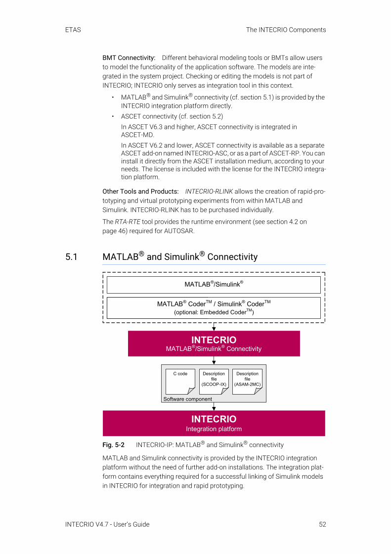
ETAS The INTECRIO Components
BMT Connectivity: Different behavioral modeling tools or BMTs allow users to model the functionality of the application software. The models are inte-grated in the system project. Checking or editing the models is not part of INTECRIO; INTECRIO only serves as integration tool in this context.
• MATLAB® and Simulink® connectivity (cf. section 5.1) is provided by the INTECRIO integration platform directly.
• ASCET connectivity (cf. section 5.2)In ASCET V6.3 and higher, ASCET connectivity is integrated in ASCET-MD.In ASCET V6.2 and lower, ASCET connectivity is available as a separate ASCET add-on named INTECRIO-ASC, or as a part of ASCET-RP. You can install it directly from the ASCET installation medium, according to your needs. The license is included with the license for the INTECRIO integra-tion platform.
Other Tools and Products: INTECRIO-RLINK allows the creation of rapid-pro-totyping and virtual prototyping experiments from within MATLAB and Simulink. INTECRIO-RLINK has to be purchased individually.
The RTA-RTE tool provides the runtime environment (see section 4.2 on page 46) required for AUTOSAR.
5.1 MATLAB® and Simulink® Connectivity
Fig. 5-2 INTECRIO-IP: MATLAB® and Simulink® connectivity
MATLAB and Simulink connectivity is provided by the INTECRIO integration platform without the need of further add-on installations. The integration plat-form contains everything required for a successful linking of Simulink models in INTECRIO for integration and rapid prototyping.
INTECRIOIntegration platform
INTECRIOMATLAB®/Simulink® Connectivity
Software component
Description file
(SCOOP-IX)
Description file
(ASAM-2MC)
C code
Real-Time Workshop®
(optional: RTW Embedded CoderTM)
MATLAB®/Simulink®
MATLAB® CoderTM / Simulink® CoderTM
(optional: Embedded CoderTM)
INTECRIO V4.7 - User’s Guide 52
ETAS The INTECRIO Components
It allows the integration of code generated by MATLAB® CoderTM + Simulink® CoderTM + (optional) Embedded CoderTM.
MATLAB and Simulink versions R2014a – R2020a (both 32 bit1 and 64 bit) and their related service packs known at the time of the INTECRIO V4.7 release are supported. If several supported MATLAB and Simulink versions (e.g. R2015b and R2018a) are installed, all of them are supported at the same time.
Unsupported MATLAB and Simulink versions cannot be used to create code for use with INTECRIO.
Model code created with MATLAB and Simulink R2006b – R2013b can still be imported and integrated in INTECRIO V4.7.
During the installation of MATLAB and Simulink connectivity, the MATLAB and Simulink installation is adjusted so that MATLAB and Simulink can interact with INTECRIO.
MATLAB and Simulink connectivity has the following tasks:
• Providing the INTECRIO target irt.tlc that must be selected if the Simulink model must be further processed with INTECRIO.
• Providing the INTECRIO target ier.tlc that must be selected if the Simulink model to be used in INTECRIO was created with the MATLAB Coder + Simulink Coder + Embedded Coder software.
• Providing the automatic creation of the SCOOP-IX description file (see chapter 6) during code generation with one of the following setups:– MATLAB Coder + Simulink Coder– MATLAB Coder + Simulink Coder + Embedded CoderThe contents of this description file is explained in section 5.1.2.
• Providing the option to start the integration in a newly created INTECRIO system and the INTECRIO build process directly from Simulink (one-click prototyping).
• Automatic re-import of the model in INTECRIO after changes and new code generation in Simulink.
If no MATLAB and Simulink installation was available during INTECRIO installa-tion, or if you want to change the MATLAB and Simulink version associated with INTECRIO, proceed as follows.
To connect INTECRIO and MATLAB and Simulink subsequently:
1. Install MATLAB and Simulink as described in the relevant installation instructions.
1. available until R2015b
NOTEIf you want to use a network installation of MATLAB and Simulink, click on the Help button and follow the instructions given in the message window.
INTECRIO V4.7 - User’s Guide 53
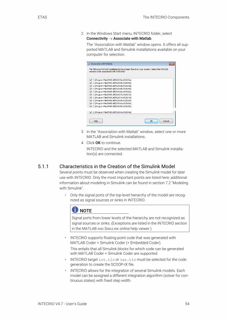
ETAS The INTECRIO Components
2. In the Windows Start menu, INTECRIO folder, select Connectivity → Associate with Matlab.The "Association with Matlab" window opens. It offers all sup-ported MATLAB and Simulink installations available on your computer for selection.
3. In the "Association with Matlab" window, select one or more MATLAB and Simulink installations.
4. Click OK to continue.INTECRIO and the selected MATLAB and Simulink installa-tion(s) are connected.
5.1.1 Characteristics in the Creation of the Simulink ModelSeveral points must be observed when creating the Simulink model for later use with INTECRIO. Only the most important points are listed here; additional information about modeling in Simulink can be found in section 7.2 "Modeling with Simulink".
• Only the signal ports of the top-level hierarchy of the model are recog-nized as signal sources or sinks in INTECRIO.
• INTECRIO supports floating-point code that was generated with MATLAB Coder + Simulink Coder (+ Embedded Coder).This entails that all Simulink blocks for which code can be generated with MATLAB Coder + Simulink Coder are supported.
• INTECRIO target irt.tlc or ier.tlc must be selected for the code generation to create the SCOOP-IX file.
• INTECRIO allows for the integration of several Simulink models. Each model can be assigned a different integration algorithm (solver for con-tinuous states) with fixed step width.
NOTESignal ports from lower levels of the hierarchy are not recognized as signal sources or sinks. (Exceptions are listed in the INTECRIO section in the MATLAB AND SIMULINK online help viewer.)
INTECRIO V4.7 - User’s Guide 54
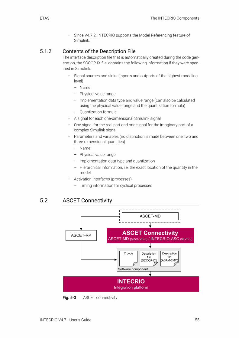
ETAS The INTECRIO Components
• Since V4.7.2, INTECRIO supports the Model Referencing feature of Simulink.
5.1.2 Contents of the Description FileThe interface description file that is automatically created during the code gen-eration, the SCOOP-IX file, contains the following information if they were spec-ified in Simulink:
• Signal sources and sinks (inports and outports of the highest modeling level)– Name– Physical value range– Implementation data type and value range (can also be calculated
using the physical value range and the quantization formula)– Quantization formula
• A signal for each one-dimensional Simulink signal• One signal for the real part and one signal for the imaginary part of a
complex Simulink signal• Parameters and variables (no distinction is made between one, two and
three-dimensional quantities)– Name– Physical value range– implementation data type and quantization– Hierarchical information, i.e. the exact location of the quantity in the
model• Activation interfaces (processes)
– Timing information for cyclical processes
5.2 ASCET Connectivity
Fig. 5-3 ASCET connectivity
ASCET-RP
INTECRIOIntegration platform
ASCET ConnectivityASCET-MD (since V6.3) / INTECRIO-ASC (til V6.2)
ASCET-MD
Software component
Description file
(SCOOP-IX)
Description file
(ASAM-2MC)
C code
INTECRIO V4.7 - User’s Guide 55
ETAS The INTECRIO Components
ASCET Connectivity contains everything required for a successful linking of ASCET models in INTECRIO for integration and rapid prototyping.
In ASCET V6.2 and earlier, ASCET connectivity is available as an add-on named INTECRIO-ASC. During the installation of INTECRIO-ASC, the required files and settings are automatically inserted in the existing ASCET installation. INTEC-RIO-ASC supports ASCET V5.1 – V6.2; if several ASCET versions are installed, all of them are supported at the same time.1
In ASCET V6.3 and higher, ASCET connectivity is included in ASCET-MD. Noth-ing else has to be installed.
ASCET connectivity has the following tasks:
• Providing the targets Prototyping and ES900, one of which must be selected if the ASCET model is to be further processed with INTECRIO.
• Selection of INTECRIO as rapid prototyping environment in the project editor of ASCET.
• In the context of an ASCET project, provision of a special code genera-tion for INTECRIO in which all required files (C code, ASAM-MCD-2MC file, SCOOP-IX description file) are created.The contents of the SCOOP-IX description file is explained in section 5.2.2.In addition, an *.oil file is generated that contains the OS configura-tion. This file can be manually imported into INTECRIO.
• If the ASCET code generation for INTECRIO is used, automatic import of the project in INTECRIO.
• Adjusting the handling of non-resolved global variables and messages to the needs of INTECRIO.
• Providing options for the migration of existing projects.• Providing the option to start the integration in an INTECRIO system and
the INTECRIO build process directly from ASCET (one-click prototyping).• Automatic re-import of the model in INTECRIO after changes and new
code generation in ASCET.
5.2.1 Characteristics in the Creation of the ASCET ModelWhen you create an ASCET model for later use with INTECRIO, you can make use of all ASCET facilities. Keep in mind the following points:
NOTEBeginning with V4.7.3, INTECRIO no longer supports ES1000 and RTPRO-PC hardware systems. ASCET models that include either of these hardware sys-tems cannot be transferred to INTECRIO V4.7.3.
1. Besides INTECRIO-ASC, ASCET-RP V5.3 – V6.2 provide ASCET connectivity. If ASCET-RP is found on a PC, INTECRIO-ASC cannot be installed.
NOTEASCET connectivity does not support ES8xx hardware.
INTECRIO V4.7 - User’s Guide 56
ETAS The INTECRIO Components
• Receive messages without corresponding send messages form the sig-nal sinks in INTECRIO, send messages without corresponding receive messages form the signal sources in INTECRIO.If desired, you can make connected messages appear as signal sinks and sources, too.
• When your project contains unresolved messages (imported messages without corresponding export), code generation for INTECRIO produces an error message.You can resolve the messages automatically, or cancel code generation and resolve the messages manually.
• Using global variables and parameters is possible, but strongly discour-aged.
• In the project options, you must select an appropriate target so that code generation for INTECRIO is available.
5.2.2 Contents of the Description FileThe interface description file that is automatically created during the code gen-eration, the SCOOP-IX file, contains the following information if they were spec-ified in ASCET:
• Signal sources (send messages) and signal sinks (receive messages)– Name– Physical value range– Implementation data type and value range (can also be calculated
using the physical value range and the quantization formula)– Quantization formula
• Parameters and variables (no distinction is made between one, two and three-dimensional quantities)– Name– Physical value range– implementation data type and quantization– Hierarchical information, i.e. the exact location of the quantity in the
model• Activation interfaces (processes)
– Timing information for cyclical processes
5.3 The Hardware ConfiguratorDuring the development of a control algorithm, the actual controlled system must be addressed at some time so that realistic results can be achieved. The controlled system (or the technical process) appears to the rapid prototyping system as a set of sensors and actuators with which the system can be con-nected using a series of appropriate peripheral devices.
These peripheral devices must be configured so that they fit the actual techni-cal process that must be modeled. For example, for A/D converters it is possi-ble to configure the input range, scanning/keeping, etc. In addition, the signal
INTECRIO V4.7 - User’s Guide 57

ETAS The INTECRIO Components
must be conditioned to adjust it to the control algorithm. The conditioning essentially consists of converting measured electrical signals to physical signal values.
These tasks are handled by the Hardware Configurator and the target connec-tivity packages (section 5.4 and section 5.5) in INTECRIO.
If an algorithm passed the first general validation check in the virtual model, it can be examined for errors, refined and optimized until it meets the specified requirements of functionality, quality and code size. As a direct troubleshooting option, the Hardware Configurator offers, for example, to measure the signal values of the hardware directly in the ETAS Experiment Environment.
5.3.1 Discontinued HardwareBeginning with V4.7.3, INTECRIO no longer supports ES1000 and RTPRO-PC hardware systems.
Existing INTECRIO workspaces with these hardware systems can be opened in INTECRIO V4.7.3. You can view these hardware systems; the hardware sys-tems and targets are marked with a red X (see Fig. 5-4).
Fig. 5-4 INTECRIO workspace browser with discontinued hardware
You can copy their content below the target level (e.g., the Ethernet controller in Fig. 5-4) and paste it to a hardware system that supports the copied content.
You can export ES1000 and RTPRO-PC hardware systems, or parts thereof, to an *.hwx file. You cannot, however, import *.hwx files that contain the hard-ware system node or target node of an unsupported hardware system.
NOTEFuture INTECRIO versions will completely remove hardware systems con-taining ES1000 or RTPRO-PC configurations from workspaces automatically, when they are opened in INTECRIO.
If you want to continue using corresponding configurations on ES800 or ES900 hardware, it is highly recommended to export them from INTECRIO V4.7.3 to the file system, or to convert them into ES800 or ES900 configura-tions, so that they can later be imported and reused on ES800 or ES900.
INTECRIO V4.7 - User’s Guide 58
ETAS The INTECRIO Components
5.3.2 HWX Import/ExportAs an alternative to manual configuration (see section 5.4.1 or section 5.5.1), it is possible to export and import hardware descriptions (*.hwx files). For that purpose, INTECRIO provides the necessary context menu options and dialog windows.
You can import *.hwx files created with several tools1, and you can import *.hwx files exported with INTECRIO into these other tools.
The file extension *.hwx is used for two description formats, HWX1 and HWX2.
• The HWX1 format is the format used by ASCET-RP V6.0 and earlier; it is also used by the legacy HWC editor in ASCET-RP V6.1 and ASCET-RP V6.2.
• The HWX2 format is used by INTECRIO V3.2 and higher and by the Hard-ware Configurator in ASCET-RP V6.1 and higher.
INTECRIO recognizes the format automatically and switches to the appropriate import procedure.
The hardware description is mapped onto an existing or new ES900, ES800, or VP-PC hardware system during import.
The log window displays a list with information about the import procedure.
If the *.hwx file contains elements not supported by INTECRIO and the selected target, these elements are skipped, and warnings are issued.
1. INTECRIO, ASCET V6.3 or higher, ASCET V5.1 – V6.2 and INTECRIO-ASC or ASCET-RP V5.3 (or higher), INTECRIO-RLINK, or customer-specific ASCET extensions
2. ETK/XETK/FETK/XCP bypass
NOTEIf your hardware configuration contains a bypass2. configuration that requires an ASAM-MCD-2MC file, or a daisychain configuration that requires an *.xml file, keep in mind the following:
• If you export the hardware configuration, make sure that the *.a2l/*.xml files are exported, too. See the online help for details.
• For a successful import of such a hardware configuration, the *.a2l/*.xml files have to be provided at the same location as the *.hwx file. so that the HXW importer finds them automatically.
An ASAM-MCD-2MC file that was exported by ASCET may cause errors when imported in INTECRIO. It is thus strongly recommended to use only original ASAM-MCD-2MC files.
NOTEWith INTECRIO V4.7.3, you cannot import a file with HWX1 format into any hardware system.
INTECRIO V4.7 - User’s Guide 59
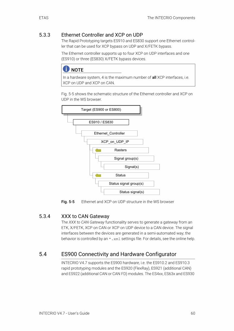
ETAS The INTECRIO Components
5.3.3 Ethernet Controller and XCP on UDPThe Rapid Prototyping targets ES910 and ES830 support one Ethernet control-ler that can be used for XCP bypass on UDP and X/FETK bypass.
The Ethernet controller supports up to four XCP on UDP interfaces and one (ES910) or three (ES830) X/FETK bypass devices.
Fig. 5-5 shows the schematic structure of the Ethernet controller and XCP on UDP in the WS browser.
Fig. 5-5 Ethernet and XCP on UDP structure in the WS browser
5.3.4 XXX to CAN GatewayThe XXX to CAN Gateway functionality serves to generate a gateway from an ETK, X/FETK, XCP on CAN or XCP on UDP device to a CAN device. The signal interfaces between the devices are generated in a semi-automated way; the behavior is controlled by an *.xml settings file. For details, see the online help.
5.4 ES900 Connectivity and Hardware ConfiguratorINTECRIO V4.7 supports the ES900 hardware, i.e. the ES910.2 and ES910.3 rapid prototyping modules and the ES920 (FlexRay), ES921 (additional CAN) and ES922 (additional CAN or CAN FD) modules. The ES4xx, ES63x and ES930
NOTEIn a hardware system, 4 is the maximum number of all XCP interfaces, i.e. XCP on UDP and XCP on CAN.
Ethernet_Controller
XCP_on_UDP_IP
Status signal(s)
Status signal group(s)
ES910 / ES830
Rasters
Status
Signal(s)
Signal group(s)
Target (ES900 or ES800)
INTECRIO V4.7 - User’s Guide 60

ETAS The INTECRIO Components
modules are supported, too. In combination with ES900 connectivity, the Hard-ware Configurator (HC) is provided for the integration and configuration of this hardware.
Fig. 5-6 INTECRIO-RP: ES900 connectivity
The Hardware Configurator allows the configuration of ES900 hardware sys-tems to provide real physical signals for inputs and outputs of the model, which can be linked with the software function model in the project configurator (see section 5.7). It is used to configure interfaces available in the ES900 for the experiment. They do not have to be installed at the time of configuration.
Information about the individual interfaces can be found in section 5.4.2 and in the manuals of the hardware products.
5.4.1 ES900 Configuration in the Hardware ConfiguratorThe Hardware Configurator contains the following components required for ES900 configuration:
• A framework that provides the basic editor and connections to other INTECRIO components (e.g. OS configurator, project integrator, ETAS Experiment Environment), among others.
NOTEThe ES900 configuration capabilities of the Hardware Configurator are only available if you installed the INTECRIO-RP package and have an appropriate license key.
ES900
INTECRIOIntegration platform (including HC)
INTECRIO-RPES900 Connectivity
*.a2l*.cod
ES4xx
ES63x...
ES930
INTECRIO V4.7 - User’s Guide 61
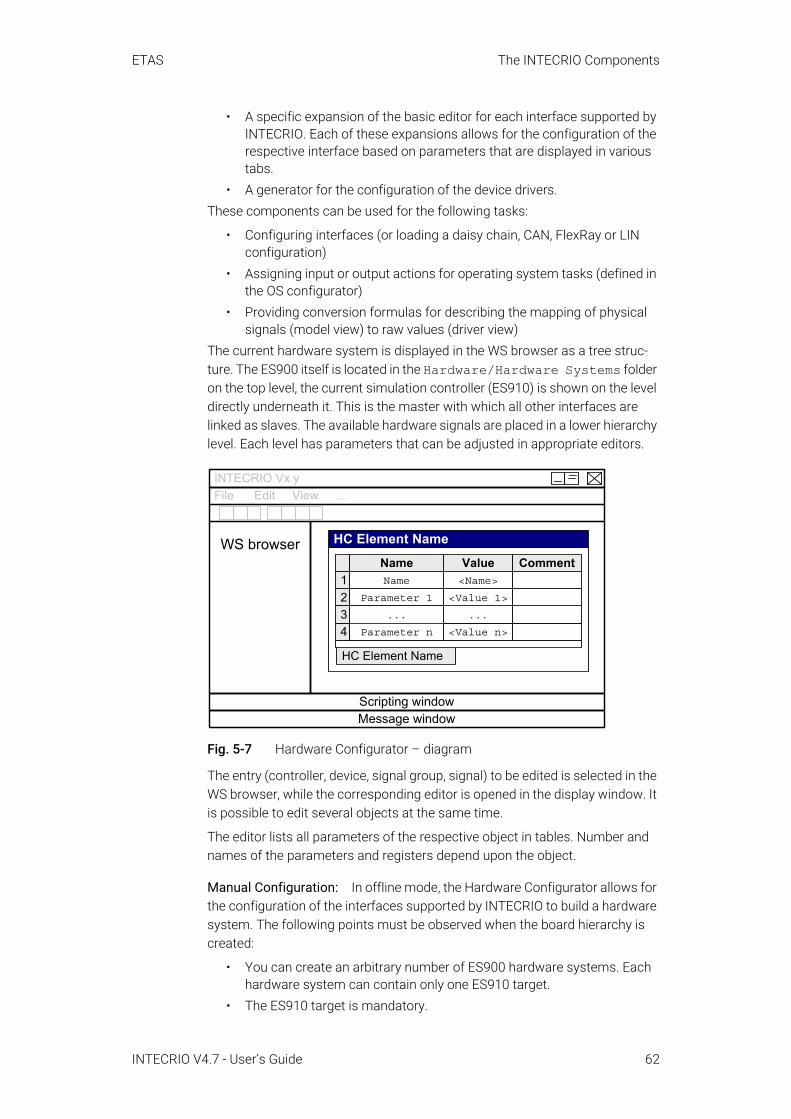
ETAS The INTECRIO Components
• A specific expansion of the basic editor for each interface supported by INTECRIO. Each of these expansions allows for the configuration of the respective interface based on parameters that are displayed in various tabs.
• A generator for the configuration of the device drivers.These components can be used for the following tasks:
• Configuring interfaces (or loading a daisy chain, CAN, FlexRay or LIN configuration)
• Assigning input or output actions for operating system tasks (defined in the OS configurator)
• Providing conversion formulas for describing the mapping of physical signals (model view) to raw values (driver view)
The current hardware system is displayed in the WS browser as a tree struc-ture. The ES900 itself is located in the Hardware/Hardware Systems folder on the top level, the current simulation controller (ES910) is shown on the level directly underneath it. This is the master with which all other interfaces are linked as slaves. The available hardware signals are placed in a lower hierarchy level. Each level has parameters that can be adjusted in appropriate editors.
Fig. 5-7 Hardware Configurator – diagram
The entry (controller, device, signal group, signal) to be edited is selected in the WS browser, while the corresponding editor is opened in the display window. It is possible to edit several objects at the same time.
The editor lists all parameters of the respective object in tables. Number and names of the parameters and registers depend upon the object.
Manual Configuration: In offline mode, the Hardware Configurator allows for the configuration of the interfaces supported by INTECRIO to build a hardware system. The following points must be observed when the board hierarchy is created:
• You can create an arbitrary number of ES900 hardware systems. Each hardware system can contain only one ES910 target.
• The ES910 target is mandatory.
File Edit View ...
Message window
WS browser HC Element Name
HC Element Name
Value<Name>
<Value n>
...
<Value 1>
NameName
Parameter 1
...
Parameter n
Comment12
43
Scripting window
INTECRIO Vx.y
INTECRIO V4.7 - User’s Guide 62

ETAS The INTECRIO Components
• A hierarchy consists of the target as master and one or several slave interfaces controlled by the master.
• All slave interfaces are located on the same hierarchy level; a slave inter-face cannot have its own slave interfaces.
• Each slave interface is assigned to its master.• Some interfaces are present several times in an ES900 system. Tab. 5-1
lists the available numbers of interfaces.
Tab. 5-1 Number of interfaces/elements per system controller
ES910 RemarksCAN Controller 0 – 2 (4) two additional classic CAN interfaces
with ES921two additional classic CAN/CAN FD inter-faces with ES922
XCP on CAN (via CAN controller)
0 – 4 4 is the maximum number of all XCP interfaces, i.e. XCP on CAN and XCP on UDP.
LIN 0 – 2 The LIN interfaces use the same ES910 hardware connectors as the main two CAN interfaces.With a suitable cable, you can use CAN and LIN simultaneously.
ETK Bypass 0 – 1 Can be used as hook-based bypass or service-based bypass.
SystemDevice 0 – 1ES920 (FlexRay) 0 – 1Daisychain (IO interface)
0 – 1 A chain of ES4xx and/or ES63x and/or ES930 modules.
Ethernet and XCP on UDP
0 – 4 See section 5.3.3 on page 60 for details.4 is the maximum number of all XCP interfaces, i.e. XCP on CAN and XCP on UDP.
Ethernet and X/FETK_Bypass
0 – 1 Can be used as hook-based bypass or service-based bypass.The X/FETK bypass device is used for both XETK and FETK.
NOTEINTECRIO supports ETK, XETK and FETK on ES900 systems. X/FETK bypass is supported via the Ethernet controller with an X/FETK bypass device in the INTECRIO hardware configuration. In addition, XETK can be accessed via XCP bypass.
To connect the XETK hardware, the ECU port on the ES910 is used. To connect the FETK, an ES891or ES892 must be connected via its FETK2/GE Port to the ECU Port of the ES910. The FETK must be con-nected to the ES891/ES892 via its FETK1/GE Port. See the INTECRIO online help for details on X/FETK configuration.
INTECRIO V4.7 - User’s Guide 63
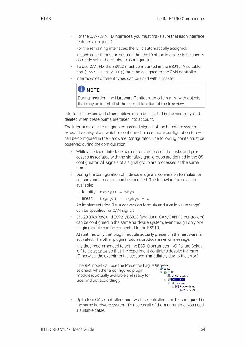
ETAS The INTECRIO Components
• For the CAN/CAN FD interfaces, you must make sure that each interface features a unique ID.For the remaining interfaces, the ID is automatically assigned. In each case, it must be ensured that the ID of the interface to be used is correctly set in the Hardware Configurator.
• To use CAN FD, the ES922 must be mounted in the ES910. A suitable port (CAN* (ES922 FD)) must be assigned to the CAN controller.
• Interfaces of different types can be used with a master.
Interfaces, devices and other sublevels can be inserted in the hierarchy, and deleted when these points are taken into account.
The interfaces, devices, signal groups and signals of the hardware system—except the daisy chain which is configured in a separate configuration tool—can be configured in the Hardware Configurator. The following points must be observed during the configuration:
• While a series of interface parameters are preset, the tasks and pro-cesses associated with the signals/signal groups are defined in the OS configurator. All signals of a signal group are processed at the same time.
• During the configuration of individual signals, conversion formulas for sensors and actuators can be specified. The following formulas are available:– Identity: f(phys) = phys– linear: f(phys) = a*phys + b
• An implementation (i.e. a conversion formula and a valid value range) can be specified for CAN signals.
• ES920 (FlexRay) and ES921/ES922 (additional CAN/CAN FD controllers) can be configured in the same hardware system, even though only one plugin module can be connected to the ES910.At runtime, only that plugin module actually present in the hardware is activated. The other plugin modules produce an error message.It is thus recommended to set the ES910 parameter "I/O Failure Behav-ior" to continue so that the experiment continues despite the error. (Otherwise, the experiment is stopped immediately due to the error.)
• Up to four CAN controllers and two LIN controllers can be configured in the same hardware system. To access all of them at runtime, you need a suitable cable.
NOTEDuring insertion, the Hardware Configurator offers a list with objects that may be inserted at the current location of the tree view.
The RP model can use the Presence flag to check whether a configured plugin module is actually available and ready for use, and act accordingly.
INTECRIO V4.7 - User’s Guide 64
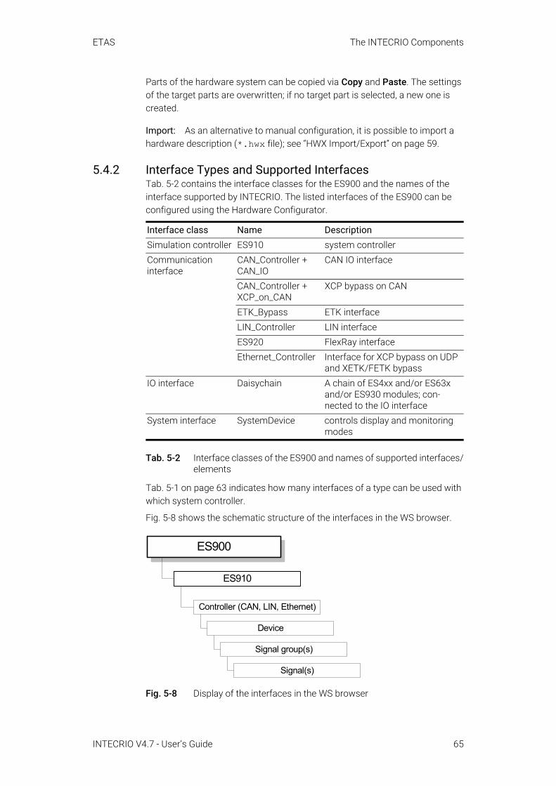
ETAS The INTECRIO Components
Parts of the hardware system can be copied via Copy and Paste. The settings of the target parts are overwritten; if no target part is selected, a new one is created.
Import: As an alternative to manual configuration, it is possible to import a hardware description (*.hwx file); see “HWX Import/Export” on page 59.
5.4.2 Interface Types and Supported InterfacesTab. 5-2 contains the interface classes for the ES900 and the names of the interface supported by INTECRIO. The listed interfaces of the ES900 can be configured using the Hardware Configurator.
Tab. 5-2 Interface classes of the ES900 and names of supported interfaces/elements
Tab. 5-1 on page 63 indicates how many interfaces of a type can be used with which system controller.
Fig. 5-8 shows the schematic structure of the interfaces in the WS browser.
Fig. 5-8 Display of the interfaces in the WS browser
Interface class Name DescriptionSimulation controller ES910 system controllerCommunication interface
CAN_Controller + CAN_IO
CAN IO interface
CAN_Controller + XCP_on_CAN
XCP bypass on CAN
ETK_Bypass ETK interfaceLIN_Controller LIN interfaceES920 FlexRay interfaceEthernet_Controller Interface for XCP bypass on UDP
and XETK/FETK bypassIO interface Daisychain A chain of ES4xx and/or ES63x
and/or ES930 modules; con-nected to the IO interface
System interface SystemDevice controls display and monitoring modes
Controller (CAN, LIN, Ethernet)
ES900
Device
Signal(s)
Signal group(s)
ES910
INTECRIO V4.7 - User’s Guide 65

ETAS The INTECRIO Components
Simulation controller: The simulation controller (ES910 in Fig. 5-8) is equipped with an Ethernet interface (named ECU on the ES910) for XCP on UDP and XETK/FETK, interfaces to the CAN/CAN FD, LIN and FlexRay bus of the vehicle, and an ETK interface.
Communication interfaces: Communication interfaces are used for distribut-ing messages on the network (such as the CAN bus). The display of supported communication interfaces in the Hardware Configurator varies so much that all are described below.
CAN Controller + CAN IO
• In the tree view, the first hierarchy level (i.e. the one underneath the ES910) is occupied by the CAN controller.
• The second hierarchy level is occupied by the CAN node (device, CAN IO).
• The third hierarchy level is occupied by folders for CAN frames (signal groups) and CAN signals.Underneath the folder for CAN frames, the hierarchy levels are occupied as follows:– The fourth hierarchy level is occupied by CAN frames (signal groups).– The fifth hierarchy level is occupied by simple CAN signals and/or
CAN signals of type multiplexor.– Underneath a CAN signal of type multiplexor, the sixth hierarchy level
is occupied by CAN multiplex groups.– The seventh hierarchy level under the CAN multiplex group is occu-
pied by CAN signals of type multiplexed.Underneath the folder for CAN signals, the hierarchy levels are occupied as follows:– The fourth hierarchy level is occupied by CAN signals of type
standard.
INTECRIO V4.7 - User’s Guide 66
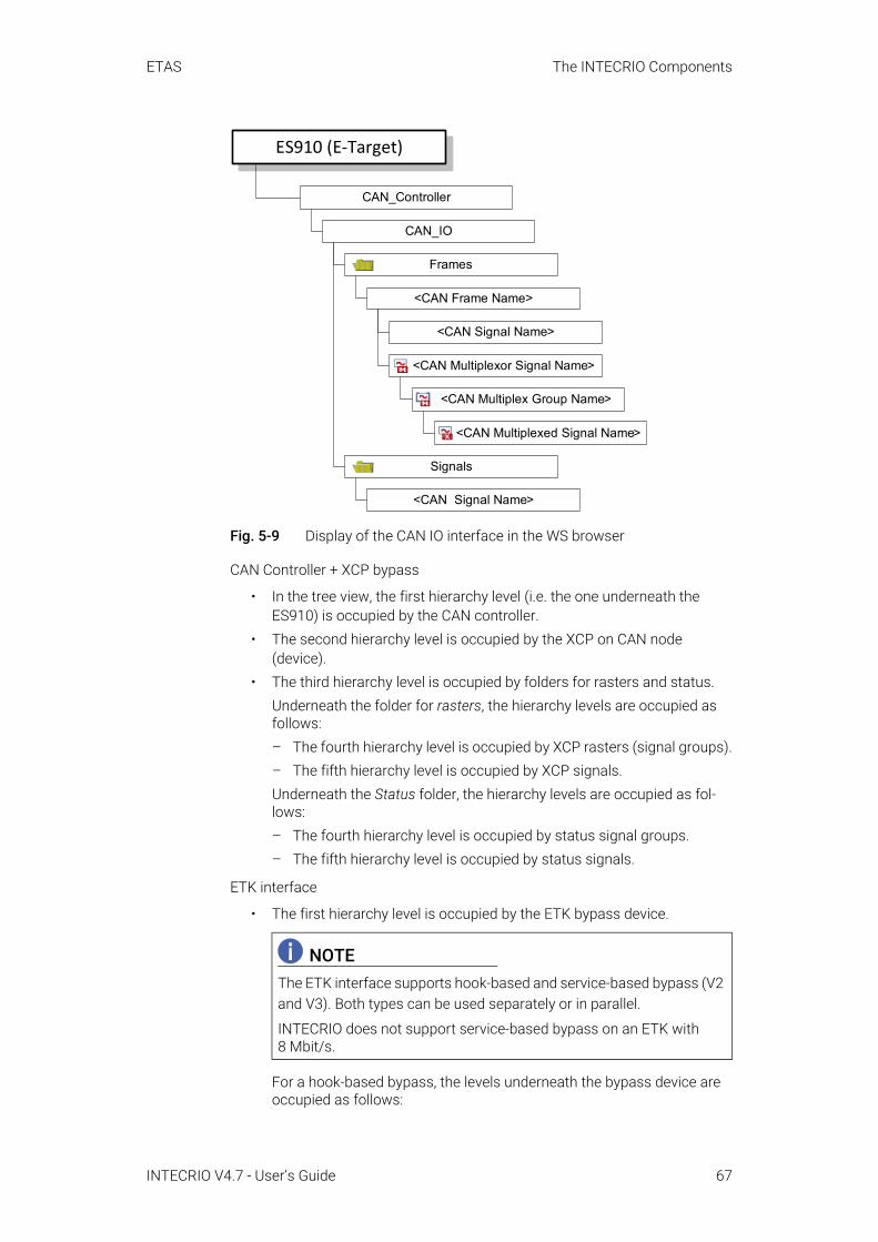
ETAS The INTECRIO Components
Fig. 5-9 Display of the CAN IO interface in the WS browser
CAN Controller + XCP bypass
• In the tree view, the first hierarchy level (i.e. the one underneath the ES910) is occupied by the CAN controller.
• The second hierarchy level is occupied by the XCP on CAN node (device).
• The third hierarchy level is occupied by folders for rasters and status.Underneath the folder for rasters, the hierarchy levels are occupied as follows:– The fourth hierarchy level is occupied by XCP rasters (signal groups).– The fifth hierarchy level is occupied by XCP signals.Underneath the Status folder, the hierarchy levels are occupied as fol-lows:– The fourth hierarchy level is occupied by status signal groups.– The fifth hierarchy level is occupied by status signals.
ETK interface
• The first hierarchy level is occupied by the ETK bypass device.
For a hook-based bypass, the levels underneath the bypass device are occupied as follows:
NOTEThe ETK interface supports hook-based and service-based bypass (V2 and V3). Both types can be used separately or in parallel.
INTECRIO does not support service-based bypass on an ETK with 8 Mbit/s.
CAN_Controller
Frames
CAN_IO
<CAN Frame Name>
<CAN Signal Name>
<CAN Multiplexor Signal Name>
<CAN Multiplex Group Name>
<CAN Multiplexed Signal Name>
Signals
<CAN Signal Name>
ES910 (E-Target)
INTECRIO V4.7 - User’s Guide 67

ETAS The INTECRIO Components
– The second hierarchy level is occupied by the signal groups for send-ing and receiving.
– The third hierarchy level is occupied by individual signals.For a service-based bypass, the levels underneath the bypass device are occupied as follows: – The second hierarchy level is occupied by the signal groups for send-
ing and receiving and by the service points and hooked service points. The ASAM-MCD-2MC file contains service point descriptions. Num-ber and configurations of the service points actually used in the bypass are determined in the service point selection editor.
– Below the signal groups, the third hierarchy level is occupied by indi-vidual signals.
– Below the service points, the third hierarchy level is occupied by the signal groups for sending and receiving. The available signal groups depend on the settings made in the ser-vice point and hooked service point selection editors.
– The fourth hierarchy level is occupied by individual signals.
LIN interface
• In the tree view, the first hierarchy level (i.e. the one underneath the ES910) is occupied by the LIN controller.
• The second hierarchy level is occupied by the LIN node (device, LIN I/O).A LIN node can be used either as master or as slave. The selected node type determines availability and direction of several items below the node level.
• The third hierarchy level is occupied by folders for schedule tables (only available for Master nodes), status display, frames, diagnostic frames, and signals.Underneath the folder for schedule tables, the hierarchy levels are occu-pied as follows:– The fourth hierarchy level is occupied by schedule tables.– The fifth level is occupied by frames of the various types.– For unconditional frames, the sixth level is occupied by signals.– For event-triggered and sporadic frames, the sixth level is occupied by
references to unconditional frames.– For event-triggered and sporadic frames, the seventh level is occupied
by references to signals of unconditional frames.Underneath the folder for status display, the hierarchy levels are occu-pied as follows:– The fourth hierarchy level is occupied by status signal groups.– The fifth hierarchy level is occupied by status signals.Underneath the folder for frames, the hierarchy levels are occupied as follows:
NOTEInstead of configuring the LIN interface manually, you can import a cluster configuration from a LIN description file.
INTECRIO V4.7 - User’s Guide 68

ETAS The INTECRIO Components
– The fourth hierarchy level is occupied by folders for event-triggered frames, sporadic frames (only available for Master nodes), and unconditional frames.
– The fifth level is occupied by frames of the various types.– For unconditional frames, the sixth level is occupied by signals.– For event-triggered and sporadic frames, the sixth level is occupied by
references to unconditional frames.– For event-triggered and sporadic frames, the seventh level is occupied
by references to signals of unconditional frames.Underneath the folder for diagnostic frames, the hierarchy levels are occupied as follows:– The fourth hierarchy level is occupied by diagnostic frames (signal
groups). – The fifth hierarchy level is occupied by diagnostic signals.Underneath the folder for signals, the hierarchy levels are occupied as follows:– The fourth hierarchy level is occupied by LIN signals of type standard.
FlexRay interface
• The first hierarchy level is occupied by the FlexRay IO device (i.e. the ES920).
• The second hierarchy level is occupied by folders for channels, status display, FlexRay frames, FlexRay PDUs, and FlexRay signals.Underneath the folder for channels, the hierarchy levels are occupied as follows:– The third hierarchy level is occupied by two channels.– The fourth hierarchy level is occupied by slots. Up to 2047 slots can
belong to one channel.– The fifth hierarchy level is occupied by frames. Up to 64 frames can
belong to one slot.– The sixth hierarchy level underneath a frame is occupied by the
frame’s PDUs.The levels below a PDU are described on Page 70.
Underneath the folder for status display, the hierarchy levels are occu-pied as follows:– The third hierarchy level is occupied by status signal groups.– The fourth hierarchy level is occupied by status signals.Underneath the folder for frames, the hierarchy levels are occupied as follows:– The third hierarchy level is occupied by FlexRay frames.– The fourth hierarchy level is occupied by FlexRay PDUs (signal
groups).– The fifth hierarchy level is occupied by simple FlexRay signals and/or
FlexRay signals of type multiplexor.– Underneath a FlexRay signal of type multiplexor, the sixth hierarchy
level is occupied by FlexRay multiplex groups.
INTECRIO V4.7 - User’s Guide 69

ETAS The INTECRIO Components
– The seventh hierarchy level under the FlexRay multiplex group is occupied by FlexRay signals of type multiplexed.
Underneath the folder for PDUs, the hierarchy levels are occupied as fol-lows:– The third hierarchy level is occupied by FlexRay PDUs (signal groups).– The fourth hierarchy level is occupied by simple FlexRay signals and/
or FlexRay signals of type multiplexor.– Underneath a FlexRay signal of type multiplexor, the fifth hierarchy
level is occupied by FlexRay multiplex groups.– The sixth hierarchy level under the FlexRay multiplex group is occu-
pied by FlexRay signals of type multiplexed.Underneath the folder for FlexRay signals, the hierarchy levels are occu-pied as follows:– The third hierarchy level is occupied by FlexRay signals of type
standard.
INTECRIO V4.7 - User’s Guide 70

ETAS The INTECRIO Components
Fig. 5-10 Display of the FlexRay interface in the WS browser
Ethernet interface: The Ethernet interface is used to configure an XCP bypass (XCP on UDP and XETK) or an X/FETK bypass.
For a description of the XCP bypass (XCP on UDP and XETK), see section 5.3.3 on page 60.
X/FETK Bypass
• In the tree view, the first level (i.e. the one underneath the ES910) is occu-pied by the Ethernet Controller.
• The second hierarchy level is occupied by the X/FETK bypass device.
FlexRay_IO (ES920)
status signal groups
status signals
channel
ES910 (E-Target)
frame(s)
slot(s)
frame(s)
PDU(s)
Channels
Status
Frames
PDU(s)+
+
signal(s)
Signals
multiplex group(s)
multiplexed signal(s)
signal(s)
multiplexor signal(s)
multiplex group(s)
multiplexed signal(s)
PDU(s) (= signal group(s))
PDU(s)
INTECRIO V4.7 - User’s Guide 71

ETAS The INTECRIO Components
• The third hierarchy level is occupied by the service points and hooked service points. The ASAM-MCD-2MC file contains service point descriptions. Number and configurations of the service points actually used in the bypass are determined in the service point selection and hooked service point selec-tion editors.
• The fourth hierarchy level is occupied by the signal groups for sending and receiving. The available signal groups depend on the settings made in the service point selection and hooked service point selection editors.
• The fifth hierarchy level is occupied by individual signals.
System interface: The system interface is used to configure the monitoring and display modes of the ES910. Signal groups for the different modes can be activated independently.
• The first hierarchy level is occupied by the system interface device.• The second hierarchy level is occupied by the signal groups for the differ-
ent modes.• The third level is occupied by the individual signals of the different
modes. The signals of a mode are predetermined.
IO interface / Daisychain: An ES4xx/ES63x/ES930 daisy chain can be con-nected to the IO interface at the back of the ES910. The WS browser in INTEC-RIO does not display the individual elements of the chain, it displays only the chain as a whole, with one signal group for each chain element and sample period.
• The first hierarchy level combines the daisy chain and the device.• The second hierarchy level is occupied by the signal groups for the differ-
ent sample periods and chain elements.• The third hierarchy level is occupied by the individual signals assigned to
the sample periods and chain elements. The actual signals depend on the daisy chain.
5.5 ES800 Connectivity and Hardware ConfiguratorINTECRIO V4.7 supports the ES800 hardware, i.e. the combination of one ES830 rapid prototyping module and up to four ES891 or ES892 or ES882 or ES886 ECU and bus interface modules.
NOTEDifferent from the other interfaces, the daisy chain cannot be configured in INTECRIO. Instead, an externally created configuration file is imported.
If the configuration file is edited, the changes must be imported, via the Update context menu, into INTECRIO.
INTECRIO V4.7 - User’s Guide 72

ETAS The INTECRIO Components
In combination with ES800 connectivity, the Hardware Configurator (HC) is pro-vided for the integration and configuration of this hardware.
Fig. 5-11 INTECRIO-RP: ES800 connectivity
The Hardware Configurator allows the configuration of ES800 hardware sys-tems to provide real physical signals for inputs and outputs of the model, which can be linked with the software function model in the project configurator (see section 5.7). It is used to configure interfaces available in the ES800 for the experiment. They do not have to be installed at the time of configuration.
Information about the individual interfaces can be found in section 5.5.2 and in the manuals of the hardware products.
5.5.1 ES800 Configuration in the Hardware ConfiguratorThe Hardware Configurator contains the following components required for ES800 configuration:
• A framework that provides the basic editor and connections to otherINTECRIO components (e.g. OS configurator, project integrator, ETASExperiment Environment), among others.
NOTEThe ES800 configuration capabilities of the Hardware Configurator are only available if you installed the INTECRIO-RP package and have an appropriate license key.
Experimenting with an ES800 hardware system requires INCA V7.2.17 or higher with INCA-EIP or the ETAS Experiment Environment V3.7.7 or higher.
INTECRIOIntegration platform (including HC)
INTECRIO-RPES800 Connectivity
*.a2l*.cod
ES800
ES4xx
ES63x...
ES930
INTECRIO V4.7 - User’s Guide 73

ETAS The INTECRIO Components
• A specific expansion of the basic editor for each interface supported by INTECRIO. Each of these expansions allows for the configuration of the respective interface based on parameters that are displayed in various tabs.
• A generator for the configuration of the device drivers.These components can be used for the following tasks:
• Configuring interfaces (or loading a daisy chain, CAN, or FlexRay config-uration)
• Assigning input or output actions for operating system tasks (defined in the OS configurator)
• Providing conversion formulas for describing the mapping of physical signals (model view) to raw values (driver view)
The current hardware system is displayed in the WS browser as a tree struc-ture. The ES800 itself is located in the Hardware/Hardware Systems folder on the top level, the combination of simulation controller (ES830) and interface modules (ES891, ES892, ES882, or ES886) is shown on the level directly below. This is the master with which all other interfaces are linked as slaves. The avail-able hardware signals are placed in a lower hierarchy level. Each level has parameters that can be adjusted in appropriate editors. Their appearance is the same as for the ES900 interface editors (cf. Fig. 5-7 on page 62).
The entry (controller, device, signal group, signal) to be edited is selected in the WS browser, while the corresponding editor is opened in the display window. It is possible to edit several objects at the same time.
The editor lists all parameters of the respective object in tables. Number and names of the parameters and registers depend upon the object.
Manual Configuration: In offline mode, the Hardware Configurator allows for the configuration of the interfaces supported by INTECRIO to build a hardware system. The following points must be observed when the hierarchy is created:
• You can create an arbitrary number of ES800 hardware systems. Each hardware system can contain only one ES830 target.
• The ES830 target is mandatory.• A hierarchy consists of the ES830 as master and one or several inter-
faces on the ES891/ES892/ES882/ES886 controlled by the master.• All slave interfaces are located on the same hierarchy level; a slave inter-
face cannot have its own slave interfaces.• Each slave interface is assigned to its master.
INTECRIO V4.7 - User’s Guide 74
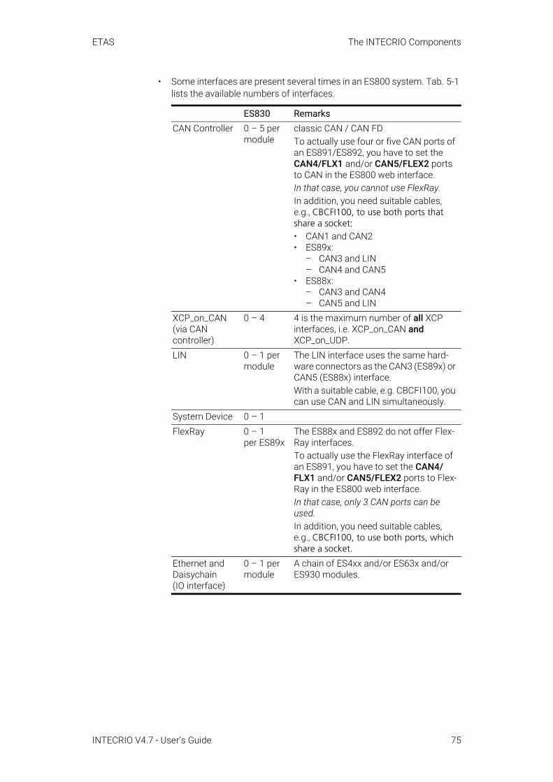
ETAS The INTECRIO Components
• Some interfaces are present several times in an ES800 system. Tab. 5-1 lists the available numbers of interfaces.
ES830 RemarksCAN Controller 0 – 5 per
moduleclassic CAN / CAN FDTo actually use four or five CAN ports of an ES891/ES892, you have to set the CAN4/FLX1 and/or CAN5/FLEX2 ports to CAN in the ES800 web interface. In that case, you cannot use FlexRay.In addition, you need suitable cables, e.g., CBCFI100, to use both ports that share a socket:• CAN1 and CAN2• ES89x:
– CAN3 and LIN – CAN4 and CAN5
• ES88x:– CAN3 and CAN4 – CAN5 and LIN
XCP_on_CAN (via CAN controller)
0 – 4 4 is the maximum number of all XCP interfaces, i.e. XCP_on_CAN and XCP_on_UDP.
LIN 0 – 1 per module
The LIN interface uses the same hard-ware connectors as the CAN3 (ES89x) or CAN5 (ES88x) interface.With a suitable cable, e.g. CBCFI100, you can use CAN and LIN simultaneously.
System Device 0 – 1FlexRay 0 – 1
per ES89xThe ES88x and ES892 do not offer Flex-Ray interfaces.To actually use the FlexRay interface of an ES891, you have to set the CAN4/FLX1 and/or CAN5/FLEX2 ports to Flex-Ray in the ES800 web interface.In that case, only 3 CAN ports can be used.In addition, you need suitable cables, e.g., CBCFI100, to use both ports, which share a socket.
Ethernet and Daisychain (IO interface)
0 – 1 per module
A chain of ES4xx and/or ES63x and/or ES930 modules.
INTECRIO V4.7 - User’s Guide 75
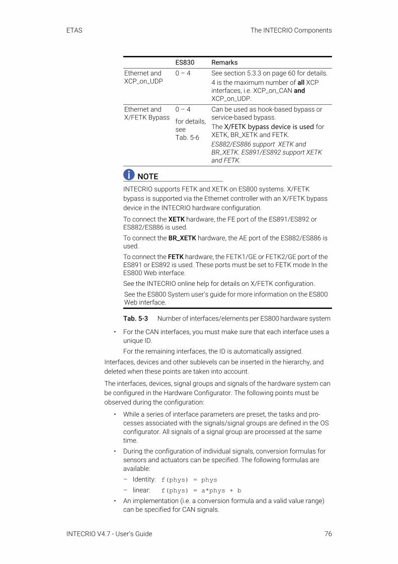
ETAS The INTECRIO Components
Tab. 5-3 Number of interfaces/elements per ES800 hardware system
• For the CAN interfaces, you must make sure that each interface uses a unique ID.For the remaining interfaces, the ID is automatically assigned.
Interfaces, devices and other sublevels can be inserted in the hierarchy, and deleted when these points are taken into account.
The interfaces, devices, signal groups and signals of the hardware system can be configured in the Hardware Configurator. The following points must be observed during the configuration:
• While a series of interface parameters are preset, the tasks and pro-cesses associated with the signals/signal groups are defined in the OS configurator. All signals of a signal group are processed at the same time.
• During the configuration of individual signals, conversion formulas for sensors and actuators can be specified. The following formulas are available:– Identity: f(phys) = phys– linear: f(phys) = a*phys + b
• An implementation (i.e. a conversion formula and a valid value range) can be specified for CAN signals.
Ethernet and XCP_on_UDP
0 – 4 See section 5.3.3 on page 60 for details.4 is the maximum number of all XCP interfaces, i.e. XCP_on_CAN and XCP_on_UDP.
Ethernet and X/FETK Bypass
0 – 4
for details, see Tab. 5-6
Can be used as hook-based bypass or service-based bypass.The X/FETK bypass device is used for XETK, BR_XETK and FETK.ES882/ES886 support XETK and BR_XETK. ES891/ES892 support XETK and FETK.
NOTEINTECRIO supports FETK and XETK on ES800 systems. X/FETK bypass is supported via the Ethernet controller with an X/FETK bypass device in the INTECRIO hardware configuration.
To connect the XETK hardware, the FE port of the ES891/ES892 or ES882/ES886 is used.To connect the BR_XETK hardware, the AE port of the ES882/ES886 is used.To connect the FETK hardware, the FETK1/GE or FETK2/GE port of the ES891 or ES892 is used. These ports must be set to FETK mode In the ES800 Web interface.See the INTECRIO online help for details on X/FETK configuration.See the ES800 System user's guide for more information on the ES800 Web interface.
ES830 Remarks
INTECRIO V4.7 - User’s Guide 76

ETAS The INTECRIO Components
• The maximum number of devices per ES89x or ES88x module is given in the INTECRIO online help. The maximum number in the hardware sys-tem depends on its consistency and setup of your ES800 stack. To access all controllers at runtime, you need suitable cables.
Parts of the hardware system can be copied via Copy and Paste. The settings of the target parts are overwritten; if no target part is selected, a new one is created.
Import: As an alternative to manual configuration, it is possible to import a hardware description (*.hwx file); see “HWX Import/Export” on page 59.
5.5.2 Interface Types and Supported InterfacesTab. 5-4 contains the interface classes for the ES800 and the names of the interface supported by INTECRIO. The listed interfaces of the ES800 can be configured using the Hardware Configurator.
Tab. 5-4 Interface classes of the ES800 and names of supported interfaces/elements
Tab. 5-3 on page 76 indicates how many interfaces of a type can be used with an ES830 per ES891, ES892, ES882, or ES886. The maximum number in the hardware system depends on its consistency and setup of your ES800 stack.
Interface class Name DescriptionSimulation controller ES830Communication interfaces (ES891, ES892, ES882, ES886)
CAN_Controller + CAN_IO
CAN IO interface
CAN_Controller + XCP_on_CAN
XCP bypass on CAN
LIN_Controller LIN interfaceFlexRay FlexRay interface (ES891 only)Ethernet_Controller + X_FETK_Bypass
Interface for XETK/BR_XETK/ FETK bypassES88x support XETK and BR_XETK. ES89x support XETK and FETK.
Ethernet_Controller + XCP_on_UDP
XCP bypass on UDP
IO interface Ethernet_Controller + Daisychain
A chain of ES4xx and/or ES63x and/or ES930 modules; con-nected to the Fast Ethernet con-troller
System interface SystemDevice controls display and monitoring modes
INTECRIO V4.7 - User’s Guide 77

ETAS The INTECRIO Components
Fig. 5-8 shows the schematic structure of the interfaces in the WS browser.
Fig. 5-12 Display of the ES800 interfaces in the WS browser
Simulation controller: The simulation controller ES830 is connected to up to four ES891 or ES892 or ES882 or ES886 interface modules. The ES89x/ES88x have no separate node in the WS browser.
Communication interfaces: An ES891 or ES892 or ES882 or ES886 is equipped with the following interfaces:
Tab. 5-5 Interfaces per ES89x/ES88x hardware module. The maximum number in the hardware system depends on its consistency and setup of your ES800 stack.
INTECRIO supports the following combinations of X/BR_X/FETK per ES89x/ES88x module in an ES800 hardware system.
Tab. 5-6 Max. number of X/BR_X/FETK per ES89x/ES88x module
Two of the ES891 ports can be used either as CAN ports or as FlexRay ports. INTECRIO supports one FlexRay controller in an ES800 hardware system.
interface modules5 interfaces to the CAN bus of the vehicle ES89x, ES88x1 interface to the FlexRay bus of the vehicle (replaces 2 CAN interfaces)
ES891
1 interface to the LIN bus of the vehicle ES89x, ES88x1 Fast Ethernet connection that can be used for XETK or daisychain
ES89x, ES88x
2 Gigabit Ethernet connections that can be used for FETK ES89x1 Automotive Ethernet connection with 3 (ES882) or 4 (ES886) ports; can be used for BR_XETK
ES88x
ES891/ES892 • one or two FETK• one XETK• one or two FETK and one XETK
ES882/ES886 • up to three BR_XETK and/or XETK
NOTEThe maximum number of X/FETK devices in an ES800 hardware system is 4.
Controller (CAN, LIN, FlexRay, Ethernet)
ES800
Device (CAN IO, XCPonCAN, LIN, X/FETK Bypass, XCPonUDP, Daisychain)
Signal Group(s)
Folders / Service Point(s)
ES830
Signal(s)
INTECRIO V4.7 - User’s Guide 78

ETAS The INTECRIO Components
CAN Controller + CAN IO
• In the tree view, the first hierarchy level (i.e. the one underneath the ES830) is occupied by the CAN controller.
• The second hierarchy level is occupied by the CAN node (device, CAN IO).
• The third hierarchy level is occupied by folders for CAN frames (signal groups) and CAN signals.Underneath the folder for CAN frames, the hierarchy levels are occupied as follows:– The fourth hierarchy level is occupied by CAN frames (signal groups).– The fifth hierarchy level is occupied by simple CAN signals and/or
CAN signals of type multiplexor.– Underneath a CAN signal of type multiplexor, the sixth hierarchy level
is occupied by CAN multiplex groups.– The seventh hierarchy level under the CAN multiplex group is occu-
pied by CAN signals of type multiplexed.Underneath the folder for CAN signals, the hierarchy levels are occupied as follows:– The fourth hierarchy level is occupied by CAN signals of type
standard.
Fig. 5-13 Display of the CAN IO interface (ES800) in the WS browser
CAN Controller + XCP bypass
• In the tree view, the first hierarchy level (i.e. the one underneath the ES830) is occupied by the CAN controller.
• The second hierarchy level is occupied by the XCP on CAN node (device).
CAN_Controller
Frames
CAN_IO
<CAN Frame Name>
<CAN Signal Name>
<CAN Multiplexor Signal Name>
<CAN Multiplex Group Name>
<CAN Multiplexed Signal Name>
Signals
<CAN Signal Name>
ES830 (E-Target)
INTECRIO V4.7 - User’s Guide 79

ETAS The INTECRIO Components
• The third hierarchy level is occupied by folders for rasters and status.Underneath the folder for rasters, the hierarchy levels are occupied as follows:– The fourth hierarchy level is occupied by XCP rasters (signal groups).– The fifth hierarchy level is occupied by XCP signals.Underneath the Status folder, the hierarchy levels are occupied as fol-lows:– The fourth hierarchy level is occupied by status signal groups.– The fifth hierarchy level is occupied by status signals.
LIN interface
• In the tree view, the first hierarchy level (i.e. the one underneath the ES830) is occupied by the LIN controller.
• The second hierarchy level is occupied by the LIN node (device, LIN I/O).A LIN node can be used either as master or as slave. The selected node type determines availability and direction of several items below the node level.
• The third hierarchy level is occupied by folders for schedule tables (only available for Master nodes), status display, frames, diagnostic frames, and signals.Underneath the folder for schedule tables, the hierarchy levels are occu-pied as follows:– The fourth hierarchy level is occupied by schedule tables.– The fifth level is occupied by frames of the various types.– For unconditional frames, the sixth level is occupied by signals.– For event-triggered and sporadic frames, the sixth level is occupied by
references to unconditional frames.– For event-triggered and sporadic frames, the seventh level is occupied
by references to signals of unconditional frames.Underneath the folder for status display, the hierarchy levels are occu-pied as follows:– The fourth hierarchy level is occupied by status signal groups.– The fifth hierarchy level is occupied by status signals.Underneath the folder for frames, the hierarchy levels are occupied as follows:– The fourth hierarchy level is occupied by folders for event-triggered
frames, sporadic frames (only available for Master nodes), and unconditional frames.
– The fifth level is occupied by frames of the various types.– For unconditional frames, the sixth level is occupied by signals.– For event-triggered and sporadic frames, the sixth level is occupied by
references to unconditional frames.
NOTEInstead of configuring the LIN interface manually, you can import a cluster configuration from a LIN description file.
INTECRIO V4.7 - User’s Guide 80
ETAS The INTECRIO Components
– For event-triggered and sporadic frames, the seventh level is occupied by references to signals of unconditional frames.
Underneath the folder for diagnostic frames, the hierarchy levels are occupied as follows:– The fourth hierarchy level is occupied by diagnostic frames (signal
groups). – The fifth hierarchy level is occupied by diagnostic signals.Underneath the folder for signals, the hierarchy levels are occupied as follows:– The fourth hierarchy level is occupied by LIN signals of type standard.
FlexRay interface
• The first hierarchy level is occupied by the FlexRay device.• The second hierarchy level is occupied by folders for status display,
channels, FlexRay frames, FlexRay PDUs, and FlexRay signals.Underneath the folder for status display, the hierarchy levels are occu-pied as follows:– The third hierarchy level is occupied by status signal groups.– The fourth hierarchy level is occupied by status signals.Underneath the folder for channels, the hierarchy levels are occupied as follows:– The third hierarchy level is occupied by two channels.– The fourth hierarchy level is occupied by slots. Up to 2047 slots can
belong to one channel.– The fifth hierarchy level is occupied by frames. Up to 64 frames can
belong to one slot.– The sixth hierarchy level underneath a frame is occupied by the
frame’s PDUs.The levels below a PDU are described on Page 81.
Underneath the folder for frames, the hierarchy levels are occupied as follows:– The third hierarchy level is occupied by FlexRay frames.– The fourth hierarchy level is occupied by FlexRay PDUs (signal
groups).– The fifth hierarchy level is occupied by simple FlexRay signals and/or
FlexRay signals of type multiplexor.– Underneath a FlexRay signal of type multiplexor, the sixth hierarchy
level is occupied by FlexRay multiplex groups.– The seventh hierarchy level under the FlexRay multiplex group is
occupied by FlexRay signals of type multiplexed.Underneath the folder for PDUs, the hierarchy levels are occupied as fol-lows:– The third hierarchy level is occupied by FlexRay PDUs (signal groups).
NOTEOnly ES891 offers a FlexRay interface.
INTECRIO V4.7 - User’s Guide 81

ETAS The INTECRIO Components
– The fourth hierarchy level is occupied by simple FlexRay signals and/or FlexRay signals of type multiplexor.
– Underneath a FlexRay signal of type multiplexor, the fifth hierarchy level is occupied by FlexRay multiplex groups.
– The sixth hierarchy level under the FlexRay multiplex group is occu-pied by FlexRay signals of type multiplexed.
Underneath the folder for FlexRay signals, the hierarchy levels are occu-pied as follows:– The third hierarchy level is occupied by FlexRay signals of type
standard.See Fig. 5-10 on page 71 for a schematic display of the FlexRay interface.
Ethernet interface: The Gigabit Ethernet interfaces and/or the Fast Ethernet interface of the ES891 or ES892 can be used to configure an X/FETK bypass.
The Fast Ethernet interface of the ES882 or ES886 can be used to configure an XETK bypass, and the Automotive Ethernet interface of the ES882 or ES886 can be used to configure a BR_XETK bypass.
For a description of the XCP bypass (XCP on UDP and X/FETK), see section 5.3.3 on page 60.
X/FETK Bypass
• In the tree view, the first level (i.e. the one underneath the ES830) is occu-pied by the Ethernet Controller.
• The second hierarchy level is occupied by the X/FETK bypass device.• The third hierarchy level is occupied by the service points and hooked
service points. The ASAM-MCD-2MC file contains service point descriptions. Number and configurations of the service points actually used in the bypass are determined in the service point selection and hooked service point selec-tion editors.
• The fourth hierarchy level is occupied by the signal groups for sending and receiving. The available signal groups depend on the settings made in the service point selection and hooked service point selection editors.
• The fifth hierarchy level is occupied by individual signals.
NOTEThe ES800 hardware system supports only X/FETK bypass.
Tab. 5-6 lists the max. number of bypass devices that can be used simultane-ously on a particular ES89x/ES88x module, and the possible X/BR_X/FETK type combinations.
INTECRIO V4.7 - User’s Guide 82

ETAS The INTECRIO Components
IO interface / Daisy Chain: An ES4xx/ES63x/ES930 daisy chain can be con-nected to the Fast Ethernet port of the ES800 target. The WS browser in INTEC-RIO does not display the individual elements of the chain, it displays only the chain as a whole, with one signal group for each chain element and sample period.
• The first hierarchy level contains the Ethernet controller.• The second hierarchy level contains the daisy chain device.• The third hierarchy level is occupied by the signal groups for the different
sample periods and chain elements.• The fourth hierarchy level is occupied by the individual signals assigned
to the sample periods and chain elements. The actual signals depend on the daisy chain.
System interface: The system interface is used to configure the monitoring and display modes of the ES830. Signal groups for the different modes can be activated independently.
• The first hierarchy level is occupied by the system interface device.• The second hierarchy level is occupied by the signal groups for the differ-
ent modes.• The third level is occupied by the individual signals of the different
modes. The signals of a mode are predetermined.
NOTEDifferent from the other interfaces, the daisy chain cannot be configured in INTECRIO. Instead, an externally created configuration file is imported.
If the configuration file is edited, the changes must be imported, via the Update context menu, into INTECRIO.
INTECRIO V4.7 - User’s Guide 83
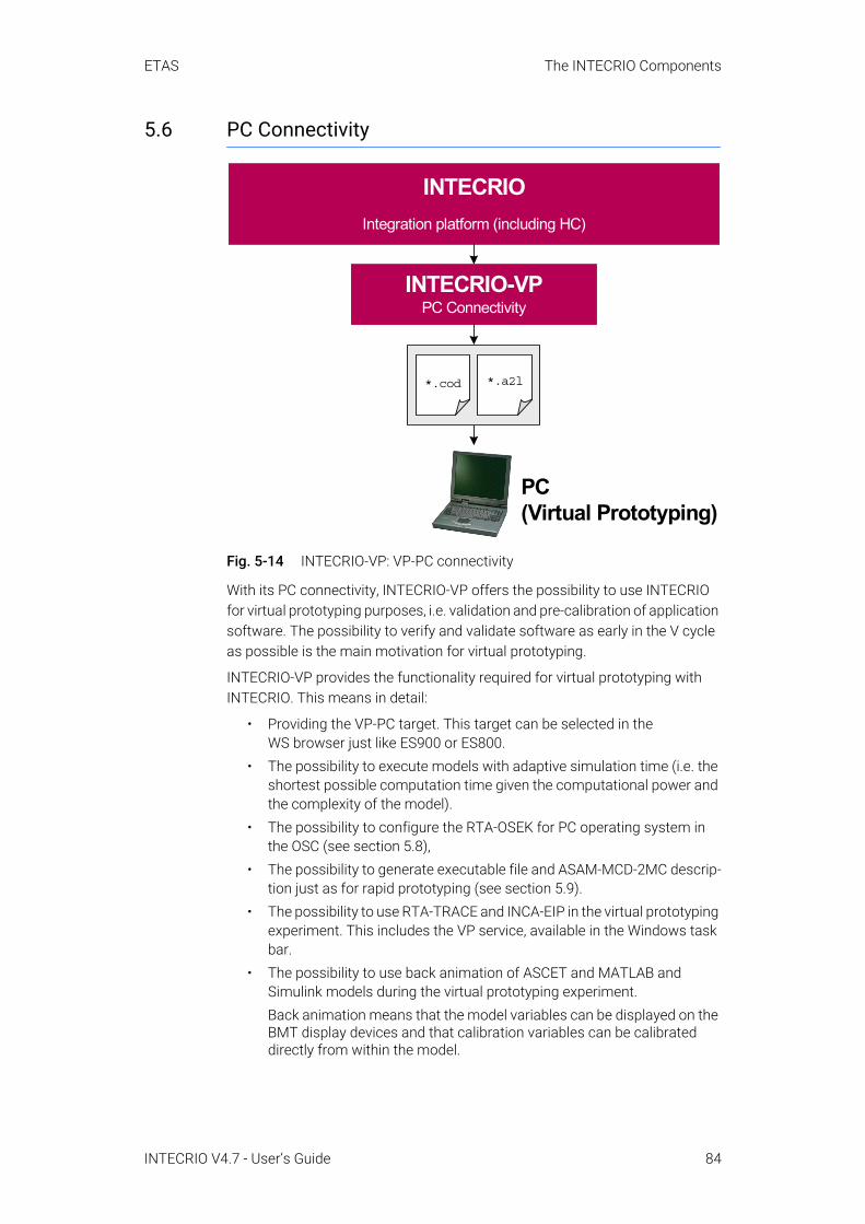
ETAS The INTECRIO Components
5.6 PC Connectivity
Fig. 5-14 INTECRIO-VP: VP-PC connectivity
With its PC connectivity, INTECRIO-VP offers the possibility to use INTECRIO for virtual prototyping purposes, i.e. validation and pre-calibration of application software. The possibility to verify and validate software as early in the V cycle as possible is the main motivation for virtual prototyping.
INTECRIO-VP provides the functionality required for virtual prototyping with INTECRIO. This means in detail:
• Providing the VP-PC target. This target can be selected in the WS browser just like ES900 or ES800.
• The possibility to execute models with adaptive simulation time (i.e. the shortest possible computation time given the computational power and the complexity of the model).
• The possibility to configure the RTA-OSEK for PC operating system in the OSC (see section 5.8),
• The possibility to generate executable file and ASAM-MCD-2MC descrip-tion just as for rapid prototyping (see section 5.9).
• The possibility to use RTA-TRACE and INCA-EIP in the virtual prototyping experiment. This includes the VP service, available in the Windows task bar.
• The possibility to use back animation of ASCET and MATLAB and Simulink models during the virtual prototyping experiment.Back animation means that the model variables can be displayed on the BMT display devices and that calibration variables can be calibrated directly from within the model.
INTECRIOIntegration platform (including HC)
INTECRIO-VPPC Connectivity
*.a2l*.cod
PC(Virtual Prototyping)
INTECRIO V4.7 - User’s Guide 84

ETAS The INTECRIO Components
• The possibility to connect to a Microsoft® Visual Studio® debugger during the virtual prototyping experiment. The table lists the versions you can use.
Tab. 5-7 Supported (X) and unsupported (–) Microsoft Visual Studio versions
The debugging possibility is limited to the following use case: Build pro-cess and experiment are performed on the same workstation, and the experiment is started immediately after the build process.
In order to simulate interrupts in a virtual ECU, the virtual machine has to manipulate the stack of the application thread asynchronously. Since many functions cannot cope with asynchronous stack changes, step-ping is not possible in every line of code.
5.7 The Project Configurator
Fig. 5-15 The project configurator
Edition
Version Professional Express
2010 X –
NOTEYou can either use back animation in a virtual prototyping experiment or connect the virtual prototyping experiment to a debugger, but not both.
NOTEIt is recommended that you set multiple breakpoints and jump from breakpoint to breakpoint. For further details, see the RTA-OSEK for PC documentation.
INTECRIO integration platform
OS ConfiguratorConfiguration ofOSEK operating
system
Project ConfiguratorNetwork list offunctions and
modules
Project IntegratorFundamental build
process for theproject integration
Module interfaceInterface forintegrating
software components
Documentor
HC
Sensor/actuatorsignal
Functionnet list
INTECRIO V4.7 - User’s Guide 85
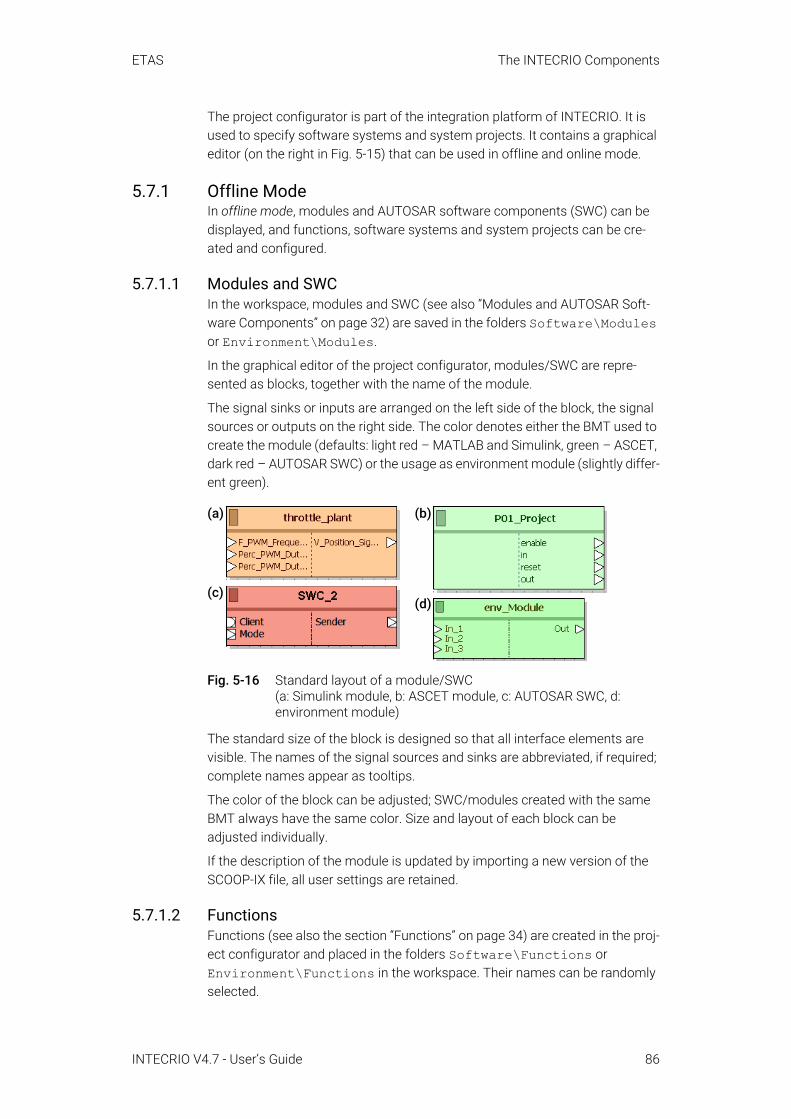
ETAS The INTECRIO Components
The project configurator is part of the integration platform of INTECRIO. It is used to specify software systems and system projects. It contains a graphical editor (on the right in Fig. 5-15) that can be used in offline and online mode.
5.7.1 Offline ModeIn offline mode, modules and AUTOSAR software components (SWC) can be displayed, and functions, software systems and system projects can be cre-ated and configured.
5.7.1.1 Modules and SWCIn the workspace, modules and SWC (see also “Modules and AUTOSAR Soft-ware Components” on page 32) are saved in the folders Software\Modules or Environment\Modules.
In the graphical editor of the project configurator, modules/SWC are repre-sented as blocks, together with the name of the module.
The signal sinks or inputs are arranged on the left side of the block, the signal sources or outputs on the right side. The color denotes either the BMT used to create the module (defaults: light red – MATLAB and Simulink, green – ASCET, dark red – AUTOSAR SWC) or the usage as environment module (slightly differ-ent green).
Fig. 5-16 Standard layout of a module/SWC (a: Simulink module, b: ASCET module, c: AUTOSAR SWC, d: environment module)
The standard size of the block is designed so that all interface elements are visible. The names of the signal sources and sinks are abbreviated, if required; complete names appear as tooltips.
The color of the block can be adjusted; SWC/modules created with the same BMT always have the same color. Size and layout of each block can be adjusted individually.
If the description of the module is updated by importing a new version of the SCOOP-IX file, all user settings are retained.
5.7.1.2 FunctionsFunctions (see also the section “Functions” on page 34) are created in the proj-ect configurator and placed in the folders Software\Functions or Environment\Functions in the workspace. Their names can be randomly selected.
(a)
(c)
(b)
(d)
INTECRIO V4.7 - User’s Guide 86

ETAS The INTECRIO Components
The interface of a function – signal sinks, signal sources – is also created in the project configurator. Implementations, signal type, etc., are adopted by the ele-ments that are connected to the inputs and outputs.
The standard layout for the external view of a function is designed just like that of a module/SWC: the signal sinks of the function are arranged on the left side, signal sources on the right side. The icons are derived from the connected module/SWC ports. The block size is selected automatically, according to the number of signal sinks and sources. The size of the function and the positions of the signal sinks and sources on their respective sides can be adjusted.
Fig. 5-17 Standard layout (external view) of a function (a) and environment function (b)
Any number of modules can be assigned to a function, but each module can be assigned only once. This restriction notwithstanding, a module can appear more than once in the graphical display of a function. Other functions cannot be assigned to a function.
The interface elements of the modules can be connected with each other in the graphical editor or the connection wizard of the project configurator or with interface elements of the function. Unused module interface elements can be removed from the graphical representation (not from the module). The follow-ing rules apply to the connections:
• Modules: A source (output) can be connected with any number of sinks (inputs).A sink (input) can be connected with exactly one source (output).
• SWC: A sender can be connected with several receivers, a server can be connected with several clients.Scalar senders and receivers with primitive typization can be connected with inputs and outputs of modules.
• Disconnected sources and sinks are allowed.• A connection between modules can be either static or dynamic.
Dynamic connections can be changed during the runtime of the pro-gram. For SWC, only static connections are possible.
5.7.1.3 Software Systems and EnvironmentsSoftware systems (see also the section “Software Systems” on page 35) and environment systems are created in the project configurator and placed in the Software\Software Systems or Environment\Environment Systems folder in the workspace. Their names can be randomly selected.
The interface of a software or environment system is created the same way as the interface of a function (see "Functions" ). The standard layout of a software or environment system corresponds to that of a function. The block size is
(a) (b)
INTECRIO V4.7 - User’s Guide 87

ETAS The INTECRIO Components
selected automatically, according to the number of signal sinks and sources. The size of the software or environment system and the positions of the signal sinks and sources on their respective sides can be adjusted.
Fig. 5-18 Standard layout of a software system (a) and environment system (b)
Any number of modules, SWC or functions can be assigned to a software or environment system. For assignment and connection, the following applies:
• In INTECRIO, modules and SWC cannot be multiply instantiated, i.e. each module or SWC can be used only once in a particular software or envi-ronment system. If several functions containing the same module/SWC are inserted in a software or environment system, the code generation issues an error message. The same happens if a module/SWC is inserted into a software or environment system both directly and as part of a function.This restriction notwithstanding, a module/SWC can appear more than once in the graphical display of a software or environment system.
• Modules, SWC and functions can be used either for software systems or for environment systems. It is not possible to use a module/SWC/func-tion imported/created for a software system in an environment system, and vice versa.
5.7.1.4 System ProjectsSimilar to functions and software or environment systems, system projects (see also “System Projects” on page 36) are created and configured in the proj-ect configurator. A system project can be assigned a hardware system, a soft-ware system, and an environment system (i.e. any number of modules and functions).
(a) (b)
INTECRIO V4.7 - User’s Guide 88
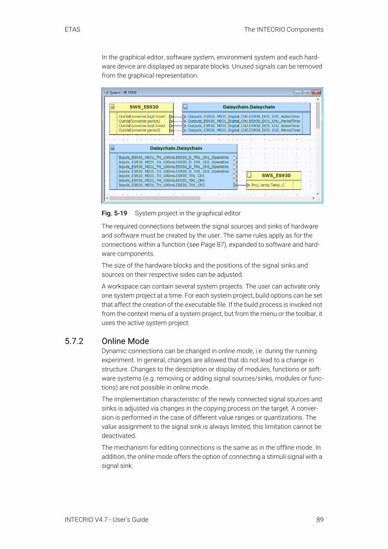
ETAS The INTECRIO Components
In the graphical editor, software system, environment system and each hard-ware device are displayed as separate blocks. Unused signals can be removed from the graphical representation.
Fig. 5-19 System project in the graphical editor
The required connections between the signal sources and sinks of hardware and software must be created by the user. The same rules apply as for the connections within a function (see Page 87), expanded to software and hard-ware components.
The size of the hardware blocks and the positions of the signal sinks and sources on their respective sides can be adjusted.
A workspace can contain several system projects. The user can activate only one system project at a time. For each system project, build options can be set that affect the creation of the executable file. If the build process is invoked not from the context menu of a system project, but from the menu or the toolbar, it uses the active system project.
5.7.2 Online ModeDynamic connections can be changed in online mode, i.e. during the running experiment. In general, changes are allowed that do not lead to a change in structure. Changes to the description or display of modules, functions or soft-ware systems (e.g. removing or adding signal sources/sinks, modules or func-tions) are not possible in online mode.
The implementation characteristic of the newly connected signal sources and sinks is adjusted via changes in the copying process on the target. A conver-sion is performed in the case of different value ranges or quantizations. The value assignment to the signal sink is always limited; this limitation cannot be deactivated.
The mechanism for editing connections is the same as in the offline mode. In addition, the online mode offers the option of connecting a stimuli signal with a signal sink.
INTECRIO V4.7 - User’s Guide 89
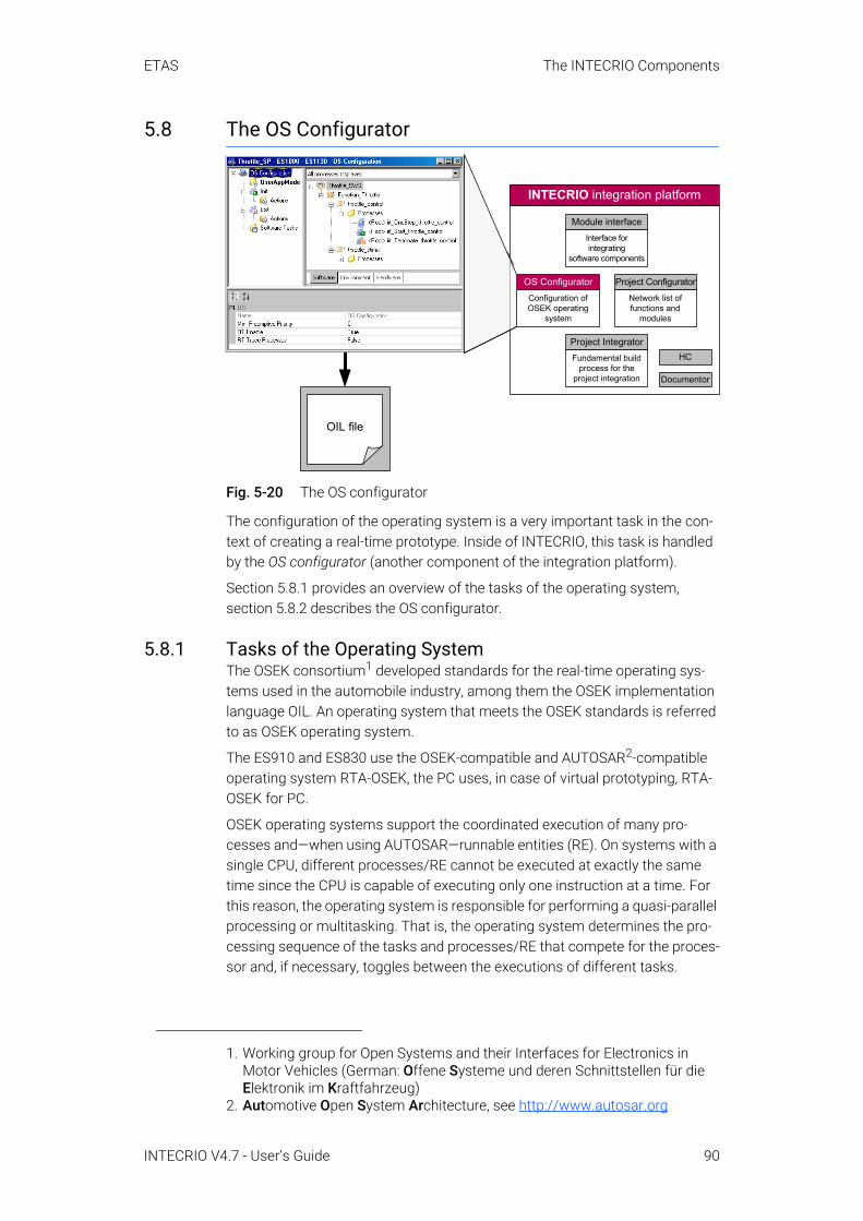
ETAS The INTECRIO Components
5.8 The OS Configurator
Fig. 5-20 The OS configurator
The configuration of the operating system is a very important task in the con-text of creating a real-time prototype. Inside of INTECRIO, this task is handled by the OS configurator (another component of the integration platform).
Section 5.8.1 provides an overview of the tasks of the operating system, section 5.8.2 describes the OS configurator.
5.8.1 Tasks of the Operating SystemThe OSEK consortium1 developed standards for the real-time operating sys-tems used in the automobile industry, among them the OSEK implementation language OIL. An operating system that meets the OSEK standards is referred to as OSEK operating system.
The ES910 and ES830 use the OSEK-compatible and AUTOSAR2-compatible operating system RTA-OSEK, the PC uses, in case of virtual prototyping, RTA-OSEK for PC.
OSEK operating systems support the coordinated execution of many pro-cesses and—when using AUTOSAR—runnable entities (RE). On systems with a single CPU, different processes/RE cannot be executed at exactly the same time since the CPU is capable of executing only one instruction at a time. For this reason, the operating system is responsible for performing a quasi-parallel processing or multitasking. That is, the operating system determines the pro-cessing sequence of the tasks and processes/RE that compete for the proces-sor and, if necessary, toggles between the executions of different tasks.
1. Working group for Open Systems and their Interfaces for Electronics in Motor Vehicles (German: Offene Systeme und deren Schnittstellen für die Elektronik im Kraftfahrzeug)
2. Automotive Open System Architecture, see http://www.autosar.org
INTECRIO integration platform
OS ConfiguratorConfiguration ofOSEK operating
system
Project ConfiguratorNetwork list offunctions and
modules
Project IntegratorFundamental build
process for theproject integration
Module interfaceInterface forintegrating
software components
Documentor
HC
OIL file
INTECRIO V4.7 - User’s Guide 90

ETAS The INTECRIO Components
5.8.1.1 SchedulingScheduling is a core function of an OSEK operating system. The scheduler must decide which process is started first from a group of activated pro-cesses/RE. The decision strategy, the so-called scheduling algorithm, is very important since it affects the real-time capabilities and the efficiency of the sys-tem. To meet the strict requirements of efficiency and real-time behavior, OSEK operating systems use a combination of static and dynamic scheduling, together with a combination of cooperative and preemptive scheduling.
Static scheduling: For static scheduling, the scheduling algorithm has all the information about the processes/RE to be scheduled and their limitations. Cus-tom limitations are calculation time, deadline, future execution times, priority relationships and mutual exclusion. Since all limitations of the processes and RE are known before the system starts, it is possible to determine the process-ing sequence of these processes/RE up front (offline). If such an offline sched-ule exists, it is sufficient to start the processes/RE at runtime at the predefined times in the predefined order.
Dynamic scheduling: For dynamic scheduling on the other hand, the algo-rithm only knows the activated processes/RE and does not have any knowl-edge of future activations. Since new processes/RE can be activated spontaneously, the scheduler must determine at runtime which one of the pro-cesses/RE must be selected.
The advantage of dynamic scheduling over static scheduling lies in the flexibil-ity with which external events can be addressed. In particular, the effectiveness of static scheduling decreases with decreasing latency period. Disadvantages of dynamic scheduling are higher demands on the computing power and need for increased memory for managing the processes/RE. Since dynamic as well as static scheduling are supported, OSEK operating systems allow for the appli-cation of combined strategies which were optimized with respect to the demands concerning response time and memory capacity.
5.8.1.2 TasksAn operational sequence or Task is defined as the result of static scheduling. It contains a sequence of processes or RE that must be executed in the specified order and with a defined priority if a certain activation event occurs.
Fig. 5-21 Task scheme
Dynamic task scheduling (or multitasking) only applies to tasks as a whole, not the individual processes/RE. Within a task, the scheduler does not have to make a decision since the processing sequence is statically specified. This
p1A p3Ap2A p4A
Time
Task
Processes
INTECRIO V4.7 - User’s Guide 91
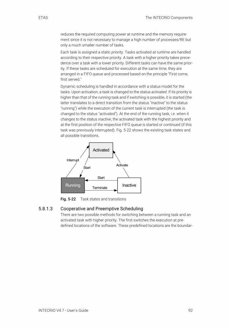
ETAS The INTECRIO Components
reduces the required computing power at runtime and the memory require-ment since it is not necessary to manage a high number of processes/RE but only a much smaller number of tasks.
Each task is assigned a static priority. Tasks activated at runtime are handled according to their respective priority. A task with a higher priority takes prece-dence over a task with a lower priority. Different tasks can have the same prior-ity. If these tasks are scheduled for execution at the same time, they are arranged in a FIFO queue and processed based on the principle "First come, first served."
Dynamic scheduling is handled in accordance with a status model for the tasks. Upon activation, a task is changed to the status activated. If its priority is higher than that of the running task and if switching is possible, it is started (the latter translates to a direct transition from the status "inactive" to the status "running") while the execution of the current task is interrupted (the task is changed to the status "activated"). At the end of the running task, i.e. when it changes to the status inactive, the activated task with the highest priority and at the first position of the respective FIFO queue is started or continued (if this task was previously interrupted). Fig. 5-22 shows the existing task states and all possible transitions.
Fig. 5-22 Task states and transitions
5.8.1.3 Cooperative and Preemptive SchedulingThere are two possible methods for switching between a running task and an activated task with higher priority. The first switches the execution at pre-defined locations of the software. These predefined locations are the boundar-
Activated
Running Inactive
Activate
Start
Terminate
Interrupt
Start
INTECRIO V4.7 - User’s Guide 92
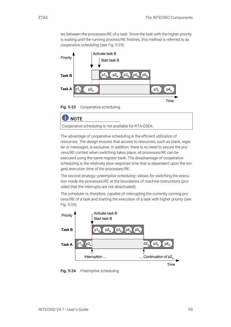
ETAS The INTECRIO Components
ies between the processes/RE of a task. Since the task with the higher priority is waiting until the running process/RE finishes, this method is referred to as cooperative scheduling (see Fig. 5-23).
Fig. 5-23 Cooperative scheduling
The advantage of cooperative scheduling is the efficient utilization of resources. The design ensures that access to resources, such as stack, regis-ter or messages, is exclusive. In addition, there is no need to secure the pro-cess/RE context when switching takes place; all processes/RE can be executed using the same register bank. The disadvantage of cooperative scheduling is the relatively slow response time that is dependent upon the lon-gest execution time of the processes/RE.
The second strategy–preemptive scheduling–allows for switching the execu-tion inside the processes/RE at the boundaries of machine instructions (pro-vided that the interrupts are not deactivated).
The scheduler is, therefore, capable of interrupting the currently running pro-cess/RE of a task and starting the execution of a task with higher priority (see Fig. 5-24).
Fig. 5-24 Preemptive scheduling
NOTECooperative scheduling is not available for RTA-OSEK.
Priority
p1A
Activate task B
Start task B
p2B p3B p5Bp1B p4B
Time
Task B
Task A p2A p3A p4A
Interruption ... … Continuation of p2A
Priority
Task B
Task A
Time
p1A p2A p2A p3A p4A
Activate task BStart task B
p2B p3B p5Bp1B p4B
INTECRIO V4.7 - User’s Guide 93
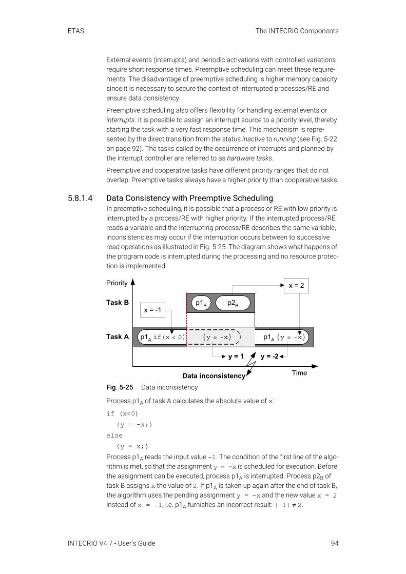
ETAS The INTECRIO Components
External events (interrupts) and periodic activations with controlled variations require short response times. Preemptive scheduling can meet these require-ments. The disadvantage of preemptive scheduling is higher memory capacity since it is necessary to secure the context of interrupted processes/RE and ensure data consistency.
Preemptive scheduling also offers flexibility for handling external events or interrupts. It is possible to assign an interrupt source to a priority level, thereby starting the task with a very fast response time. This mechanism is repre-sented by the direct transition from the status inactive to running (see Fig. 5-22 on page 92). The tasks called by the occurrence of interrupts and planned by the interrupt controller are referred to as hardware tasks.
Preemptive and cooperative tasks have different priority ranges that do not overlap. Preemptive tasks always have a higher priority than cooperative tasks.
5.8.1.4 Data Consistency with Preemptive SchedulingIn preemptive scheduling, it is possible that a process or RE with low priority is interrupted by a process/RE with higher priority. If the interrupted process/RE reads a variable and the interrupting process/RE describes the same variable, inconsistencies may occur if the interruption occurs between to successive read operations as illustrated in Fig. 5-25. The diagram shows what happens of the program code is interrupted during the processing and no resource protec-tion is implemented.
Fig. 5-25 Data inconsistency
Process p1A of task A calculates the absolute value of x:
if (x<0){y = -x;}
else{y = x;}
Process p1A reads the input value -1. The condition of the first line of the algo-rithm is met, so that the assignment y = -x is scheduled for execution. Before the assignment can be executed, process p1A is interrupted. Process p2B of task B assigns x the value of 2. If p1A is taken up again after the end of task B, the algorithm uses the pending assignment y = -x and the new value x = 2 instead of x = -1, i.e. p1A furnishes an incorrect result: |-1| ≠ 2.
y = 1
Priority x = 2
p1A if(x < 0) p1A {y = -x}{y = -x}
y = -2
Data inconsistency Time
Task A
Task Bx = -1
p1B p2B
INTECRIO V4.7 - User’s Guide 94
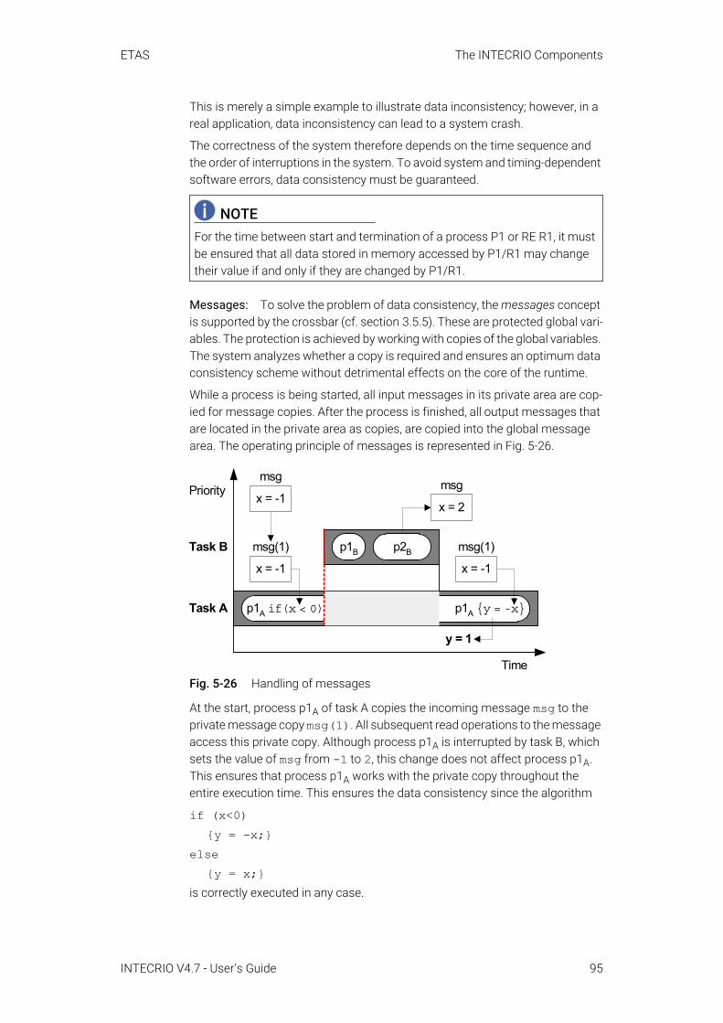
ETAS The INTECRIO Components
This is merely a simple example to illustrate data inconsistency; however, in a real application, data inconsistency can lead to a system crash.
The correctness of the system therefore depends on the time sequence and the order of interruptions in the system. To avoid system and timing-dependent software errors, data consistency must be guaranteed.
Messages: To solve the problem of data consistency, the messages concept is supported by the crossbar (cf. section 3.5.5). These are protected global vari-ables. The protection is achieved by working with copies of the global variables. The system analyzes whether a copy is required and ensures an optimum data consistency scheme without detrimental effects on the core of the runtime.
While a process is being started, all input messages in its private area are cop-ied for message copies. After the process is finished, all output messages that are located in the private area as copies, are copied into the global message area. The operating principle of messages is represented in Fig. 5-26.
Fig. 5-26 Handling of messages
At the start, process p1A of task A copies the incoming message msg to the private message copy msg(1). All subsequent read operations to the message access this private copy. Although process p1A is interrupted by task B, which sets the value of msg from -1 to 2, this change does not affect process p1A. This ensures that process p1A works with the private copy throughout the entire execution time. This ensures the data consistency since the algorithm
if (x<0){y = -x;}
else{y = x;}
is correctly executed in any case.
NOTEFor the time between start and termination of a process P1 or RE R1, it must be ensured that all data stored in memory accessed by P1/R1 may change their value if and only if they are changed by P1/R1.
Priorityx = 2
p1A if(x < 0) p1A {y = -x}
y = 1
Task A
Task Bx = -1
p1B p2B
msg
msg(1)
x = -1
msg
x = -1
msg(1)
Time
INTECRIO V4.7 - User’s Guide 95
ETAS The INTECRIO Components
When working with AUTOSAR SWC, an AUTOSAR runtime environment (RTE, cf. section 4.2) is used instead of the crossbar. If necessary, the RTE uses suit-able means of the OS (resources, interrupt blocks) to ensure consistency of the transmitted data.
5.8.1.5 Application ModesApplication Modes were developed to support different runtime configurations of the complete system at different times. They allow for a simple and flexible design and the management of system statuses of completely different func-tions. Examples of such application modes are Startup, Normal Operating Mode, Shutdown, Diagnosis and EEPROM Programming. Each application mode can be equipped with its own tasks, priorities, timer configurations, etc.
An application mode consists of two successive phases: an initialization and a normal sequence phase. During initialization, all interrupts are deactivated. This is used, for example, for the set-up of hardware registers and variables. At the end of the phase, interrupts are activated and the normal processing of the tasks begins.
NOTE RTA-OSEK, and thus INTECRIO, supports only one application mode.
INTECRIO V4.7 - User’s Guide 96

ETAS The INTECRIO Components
5.8.2 Design of the OS ConfiguratorThe design of the OS configurator of INTECRIO is shown in Fig. 5-27.
Fig. 5-27 OS configurator: Design
The figure replicates the process sequence during the configuration of the operating system.
The OSC editor is an easy to handle editor that provides the user with a quick overview of the system and allows for editing the configuration in an applica-tion-oriented display.
After completed configuration, the OIL interface creates the required configura-tion files in the OIL language (*.oil files).
However, only the OSEK conformance classes BCC1 and BCC2 are directly sup-ported. The OIL configuration files can be processed further with any OSEK operating system. The further processing in INTECRIO is based on the operat-ing systems RTA-OSEK or RTA-OSEK for PC of ETAS.
OSC editor
*.oil,*.esc
Configurator/generator (e.g. ESCAPE)
*.c, *.h
Compiling
Operating system
OIL interface
Connection to other OSEK operating systems is possible
PC
Experimental Target
OS libraries
RTA-OSEK,RTA-OSEK f. PC,...
INTECRIO V4.7 - User’s Guide 97

ETAS The INTECRIO Components
The configurator/generator generates C-code files from the *.oil files which, in turn, are used to compile the operating system while linking the operating system library. Only the completed operating system is loaded onto the experi-mental target, all previous levels are executed on the PC.
5.8.3 The OSC Editor
The interface of the OSC is divided into three parts: The top left field contains the OS configuration view, at the top right are three tabs that show the hierar-chical structures of software, environment and hardware system. You can select whether the tabs show all processes or only those that are not assigned to a task. Below these two fields if the input field for the attributes of the object selected in the OS configuration view. The attributes relevant for the object and the operating system are shown.
The OSC has two modes:
• Offline modeThe operating system is configured in offline mode. The minimal priority of preemptive tasks can be set for the operating system. It can also be defined whether tracing the runtime behavior should be handled using the tool RTA-TRACE (global or on the process level).For ASCET models, you have the additional option to configure the OS in ASCET, and then import the configuration (*.oil file) into INTECRIO.
• Online modeIn online mode, i.e. with running experiment, the setting options of the OSC are blocked. You can use the OS configurator only as display.
5.8.3.1 Creating TasksThe operating system is located on the top level of the OS configuration view.
With AUTOSAR SWC: No application mode is shown in the display. One Init and Exit task each are automatically created directly below the operating sys-tem. In addition, tasks can be created in the Software Tasks folder. The type of these tasks is defined by the assigned runnable entities.
HardwareEnvironmentSoftware
OSAppMode
Task1
Task2InitExit
ActionsEvent
ISRsSoftware Tasks
SoftwareFunction1
Module1Processes
Process1Process2
...
Priority 5Period 600...
Sys1 - Target - CPU1 - OS Configuration
File Edit View ...INTECRIO Vx .y
…
SoftwareEnvironmentSystem
Sys1
SWSys
TargetCPU1
OS
Hardware
INTECRIO V4.7 - User’s Guide 98
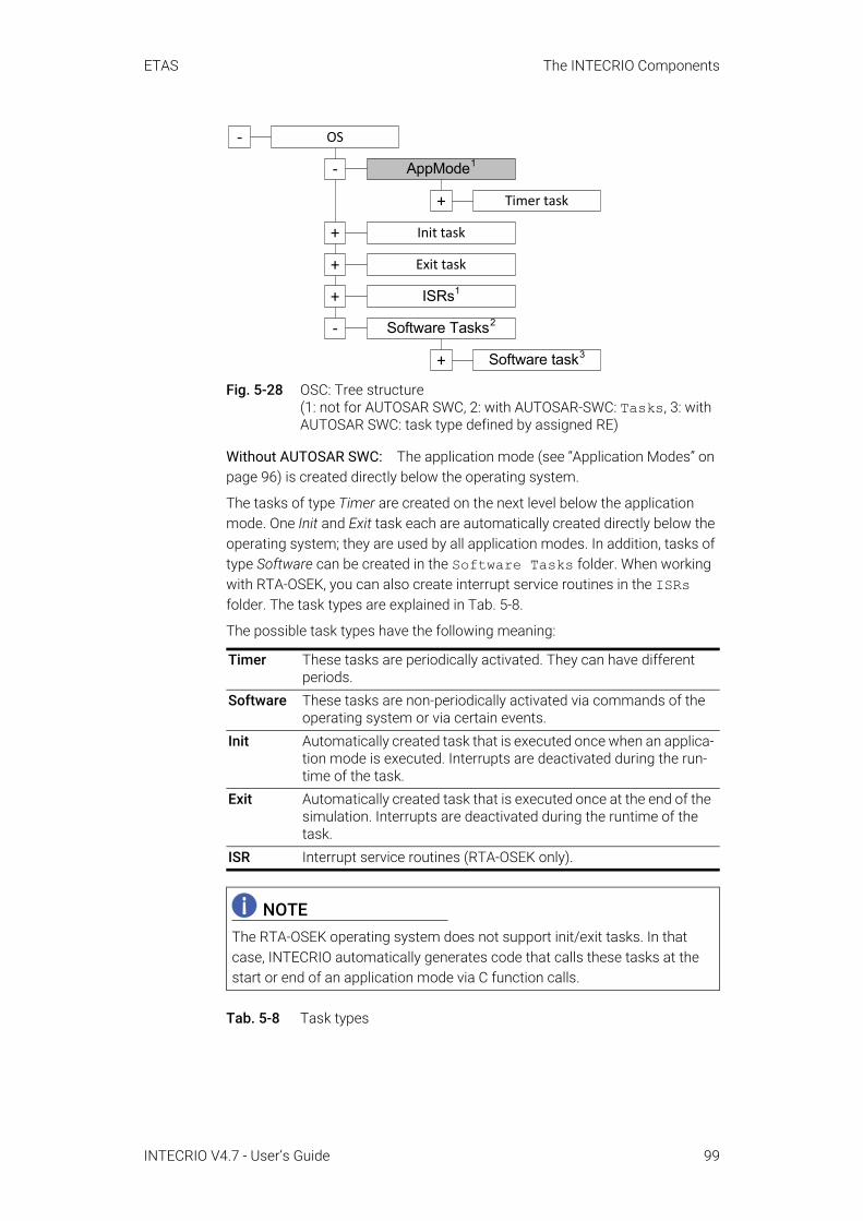
ETAS The INTECRIO Components
Fig. 5-28 OSC: Tree structure (1: not for AUTOSAR SWC, 2: with AUTOSAR-SWC: Tasks, 3: with AUTOSAR SWC: task type defined by assigned RE)
Without AUTOSAR SWC: The application mode (see “Application Modes” on page 96) is created directly below the operating system.
The tasks of type Timer are created on the next level below the application mode. One Init and Exit task each are automatically created directly below the operating system; they are used by all application modes. In addition, tasks of type Software can be created in the Software Tasks folder. When working with RTA-OSEK, you can also create interrupt service routines in the ISRs folder. The task types are explained in Tab. 5-8.
The possible task types have the following meaning:
Tab. 5-8 Task types
Timer These tasks are periodically activated. They can have different periods.
Software These tasks are non-periodically activated via commands of the operating system or via certain events.
Init Automatically created task that is executed once when an applica-tion mode is executed. Interrupts are deactivated during the run-time of the task.
Exit Automatically created task that is executed once at the end of the simulation. Interrupts are deactivated during the runtime of the task.
ISR Interrupt service routines (RTA-OSEK only).
NOTEThe RTA-OSEK operating system does not support init/exit tasks. In that case, INTECRIO automatically generates code that calls these tasks at the start or end of an application mode via C function calls.
OS
AppMode1
Init task
-
-
+
Exit task+
Timer task+
ISRs1+
Software Tasks2-
Software task3+
INTECRIO V4.7 - User’s Guide 99

ETAS The INTECRIO Components
Below the application mode, timer tasks can be created, deleted and renamed. Each task features the folders Actions and Event for processes and events.
Fig. 5-29 OSC: Application mode with assigned timer tasks
Software tasks can only be created in the Software Tasks folder. These tasks do not belong to any application mode and are not included in the sched-uling of the operating system. They can still be called during an experiment, e.g. with an event from the Hardware Configurator.
Interrupt service routines (ISRs) can only be created in the ISRs folder. The ISR sequence has no influence on the runtime behavior.
Fig. 5-30 OSC: Software task and ISR (Neither ISRs nor events exist for virtual prototyping. The respective folders are omitted in that case.)
NOTEFor virtual prototyping (target PC), the Event folder is omitted.
+
+
AppMode
Task_1
-
. . .
Actions
Event
-
Task_2+
Task_3+
+
OS
Init task
-
+
Exit task+
Software Tasks
AppMode+
Software task-
-
ISRs
Actions
Event. . .
ISR
Actions
Interrupt. . .
-
-
+
+
+
INTECRIO V4.7 - User’s Guide 100
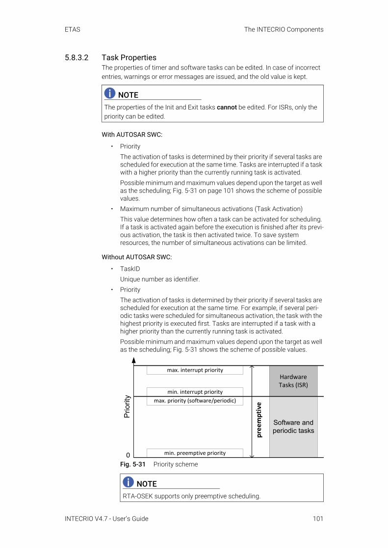
ETAS The INTECRIO Components
5.8.3.2 Task PropertiesThe properties of timer and software tasks can be edited. In case of incorrect entries, warnings or error messages are issued, and the old value is kept.
With AUTOSAR SWC:
• PriorityThe activation of tasks is determined by their priority if several tasks are scheduled for execution at the same time. Tasks are interrupted if a task with a higher priority than the currently running task is activated. Possible minimum and maximum values depend upon the target as well as the scheduling; Fig. 5-31 on page 101 shows the scheme of possible values.
• Maximum number of simultaneous activations (Task Activation)This value determines how often a task can be activated for scheduling. If a task is activated again before the execution is finished after its previ-ous activation, the task is then activated twice. To save system resources, the number of simultaneous activations can be limited.
Without AUTOSAR SWC:
• TaskIDUnique number as identifier.
• PriorityThe activation of tasks is determined by their priority if several tasks are scheduled for execution at the same time. For example, if several peri-odic tasks were scheduled for simultaneous activation, the task with the highest priority is executed first. Tasks are interrupted if a task with a higher priority than the currently running task is activated. Possible minimum and maximum values depend upon the target as well as the scheduling; Fig. 5-31 shows the scheme of possible values.
Fig. 5-31 Priority scheme
NOTEThe properties of the Init and Exit tasks cannot be edited. For ISRs, only the priority can be edited.
NOTERTA-OSEK supports only preemptive scheduling.
min. preemptive priority
min. interrupt prioritymax. priority (software/periodic)
max. interrupt priority
pree
mpt
ive
Software and periodic tasks
Hardware Tasks (ISR)
Prio
rity
0
INTECRIO V4.7 - User’s Guide 101
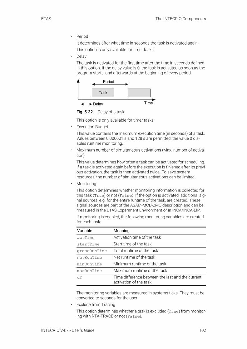
ETAS The INTECRIO Components
• PeriodIt determines after what time in seconds the task is activated again.This option is only available for timer tasks.
• DelayThe task is activated for the first time after the time in seconds defined in this option. If the delay value is 0, the task is activated as soon as the program starts, and afterwards at the beginning of every period.
Fig. 5-32 Delay of a task
This option is only available for timer tasks.• Execution Budget
This value contains the maximum execution time (in seconds) of a task. Values between 0.000001 s and 128 s are permitted; the value 0 dis-ables runtime monitoring.
• Maximum number of simultaneous activations (Max. number of activa-tion)This value determines how often a task can be activated for scheduling. If a task is activated again before the execution is finished after its previ-ous activation, the task is then activated twice. To save system resources, the number of simultaneous activations can be limited.
• Monitoring This option determines whether monitoring information is collected for this task (True) or not (False). If the option is activated, additional sig-nal sources, e.g. for the entire runtime of the task, are created. These signal sources are part of the ASAM-MCD-2MC description and can be measured in the ETAS Experiment Environment or in INCA/INCA-EIP.If monitoring is enabled, the following monitoring variables are created for each task:
The monitoring variables are measured in systems ticks. They must be converted to seconds for the user.
• Exclude from Tracing This option determines whether a task is excluded (True) from monitor-ing with RTA-TRACE or not (False).
Variable MeaningactTime Activation time of the taskstartTime Start time of the taskgrossRunTime Total runtime of the tasknetRunTime Net runtime of the taskminRunTime Minimum runtime of the taskmaxRunTime Maximum runtime of the taskdT Time difference between the last and the current
activation of the task
Task
Period
Delay Time
INTECRIO V4.7 - User’s Guide 102
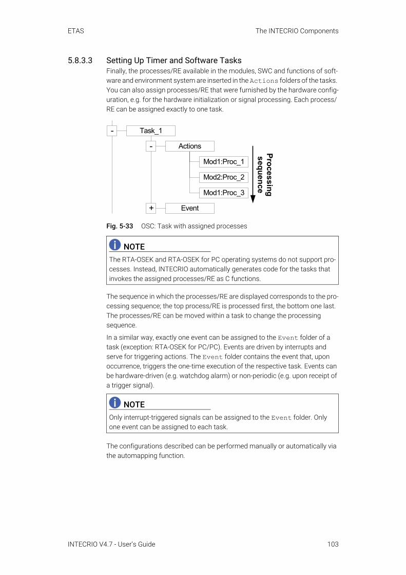
ETAS The INTECRIO Components
5.8.3.3 Setting Up Timer and Software TasksFinally, the processes/RE available in the modules, SWC and functions of soft-ware and environment system are inserted in the Actions folders of the tasks. You can also assign processes/RE that were furnished by the hardware config-uration, e.g. for the hardware initialization or signal processing. Each process/RE can be assigned exactly to one task.
Fig. 5-33 OSC: Task with assigned processes
The sequence in which the processes/RE are displayed corresponds to the pro-cessing sequence; the top process/RE is processed first, the bottom one last. The processes/RE can be moved within a task to change the processing sequence.
In a similar way, exactly one event can be assigned to the Event folder of a task (exception: RTA-OSEK for PC/PC). Events are driven by interrupts and serve for triggering actions. The Event folder contains the event that, upon occurrence, triggers the one-time execution of the respective task. Events can be hardware-driven (e.g. watchdog alarm) or non-periodic (e.g. upon receipt of a trigger signal).
The configurations described can be performed manually or automatically via the automapping function.
NOTEThe RTA-OSEK and RTA-OSEK for PC operating systems do not support pro-cesses. Instead, INTECRIO automatically generates code for the tasks that invokes the assigned processes/RE as C functions.
NOTEOnly interrupt-triggered signals can be assigned to the Event folder. Only one event can be assigned to each task.
-
Task_1
Mod1:Proc_1
Mod2:Proc_2
Mod1:Proc_3
Processingsequence
-
Actions
Event+
INTECRIO V4.7 - User’s Guide 103
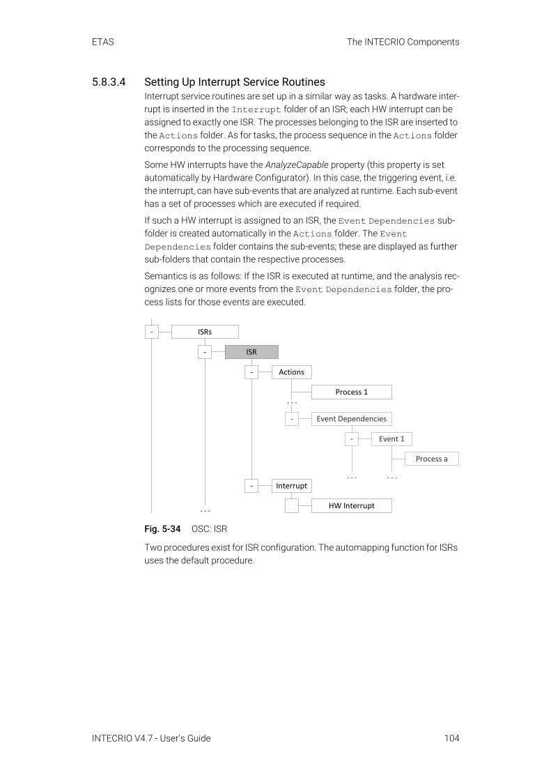
ETAS The INTECRIO Components
5.8.3.4 Setting Up Interrupt Service RoutinesInterrupt service routines are set up in a similar way as tasks. A hardware inter-rupt is inserted in the Interrupt folder of an ISR; each HW interrupt can be assigned to exactly one ISR. The processes belonging to the ISR are inserted to the Actions folder. As for tasks, the process sequence in the Actions folder corresponds to the processing sequence.
Some HW interrupts have the AnalyzeCapable property (this property is set automatically by Hardware Configurator). In this case, the triggering event, i.e. the interrupt, can have sub-events that are analyzed at runtime. Each sub-event has a set of processes which are executed if required.
If such a HW interrupt is assigned to an ISR, the Event Dependencies sub-folder is created automatically in the Actions folder. The Event Dependencies folder contains the sub-events; these are displayed as further sub-folders that contain the respective processes.
Semantics is as follows: If the ISR is executed at runtime, and the analysis rec-ognizes one or more events from the Event Dependencies folder, the pro-cess lists for those events are executed.
Fig. 5-34 OSC: ISR
Two procedures exist for ISR configuration. The automapping function for ISRs uses the default procedure.
ISRs
Actions
Interrupt
. . .
Process 1
Event Dependencies
Event 1
Process a
HW Interrupt
-
-
. . .. . .
. . .
-
-
-
ISR
-
INTECRIO V4.7 - User’s Guide 104

ETAS The INTECRIO Components
A Default
This procedure should always be used, unless urgent scheduling require-ments must be met.A HW interrupt is assigned to a newly created ISR. Within the high-prior-ity ISR, only the analysis is executed. If required, the analysis task acti-vates further tasks. These software tasks (with lower priority than the ISR) contain the processes to be executed (signal groups and user-defined processes).
B Fastest response time
This procedure should only be used if signals must be evaluated as fast as possible.After the ISR was created and the HW interrupt assigned, the event belonging to the signal is assigned to the Event Dependencies folder. The signal group, as well as the user-defined processes, are inserted in the Event <event name> subfolder.The disadvantage is that the user-defined processes are executed with the high priority of the ISR and thus block most other actions in the sys-tem.
INTECRIO V4.7 - User’s Guide 105

ETAS The INTECRIO Components
5.9 The Project Integrator
Fig. 5-35 The project integrator
The project integrator (PI) combines all the components of the system – mod-ules and functions, hardware interfacing, OS configuration, etc. – into an exe-cutable file. It essentially consists of a tool chain. The frame of this chain, i.e. the components, that provides the Make functionality is the PI build system.
Additional components are the PI plugin, which provides the variables parts of the build configuration, compiler, linker, etc.
Besides the executable file, an ASAM-MCD-2MC file is created for the experi-ment's project in which the ASAM-MCD-2MC files of the individual modules and additional information about the total project are combined. Optionally, the project integrator also creates a configuration file for RTA-TRACE.
In contrast to the configurators, the project integrator does not have its own editors. In the graphical framework, it only reveals itself by using the Integration menu.
5.9.1 The Build ProcessFor a successful build process, all necessary files (*.six, *.c, *.h, *.a2l, ...) must be available for all modules. An installation of the BMT that generated these files is not necessary.
INTECRIO integration platform
HC
Documentor
OS ConfiguratorConfiguration ofOSEK operating
system
Proj. ConfiguratorNetwork list offunctions and
modulesINTECRIO
Integration platformProject integrator
ASAM-2MCfile
executablefile
C code ASAM-2MCfile
SCOOP-IXfile
OILfile
Funct.Network
list
Hard-ware-config.Module interface
Interface forintegrating software
components
Project IntegratorFundamental build
process for theproject integration
INTECRIO V4.7 - User’s Guide 106

ETAS The INTECRIO Components
5.9.1.1 OverviewFig. 5-36 schematically displays the phases of the build process and the file types concerned. Each one of the phases, in turn, can be subdivided into indi-vidual steps.
Fig. 5-36 The build process
At the start of the build process, the parser analyzes the configurations of all components and the total project, as well as the interface descriptions pro-vided by the behavioral modeling tools (*.six).
For the code generation, the interface descriptions (*.six) and the configura-tions (*.oil, ...) created with different INTECRIO components are transferred to C code. This code contains the information required in addition to the func-tional code of the modules.
For the compiling, object files are created from the files created during the code generation and the C code of the behavioral modeling tools. External C code files or header files can be added here. Only one compiler can be used for a system project.
Generated files*.c, *.h, ...
*.c, *.h, ...Compiling
Compiler results*.o
Linker *.o,*.lib,*.loc
Linker result*.l
Post processing*.a2l
External files
External files
Code generation *.oil, ...
ASAM-2MC file*.a2l
Executable file*.a2l.cod
External files
External files
Parser
External files
*.six*.c, *.h, *.a2l,*.six, ...
BMTs, config.
*.six,*.oil,*.xml
INTECRIO V4.7 - User’s Guide 107
ETAS The INTECRIO Components
The compiling results are linked into a binary file by the linker. External object files or libraries can be added here. Only one linker can be used for a system project.
In post-processing, the final executable file and the ASAM-MCD-2MC descrip-tion file for the complete project is created from the binary file. The ASAM-MCD-2MC files generated by the behavioral modeling tools are included here.
5.9.1.2 SequenceBefore the build process can run, it must be ensured that the system project contains the following components:
• A configuration of the hardware (see section 5.3), • A configuration of the software (see section 5.7),• A completely configured system project (see section 5.7, subsection
"System Projects" ), and• An OS configuration (see section 5.8).
Once it is started, the build process runs automatically. Information about the current status and warnings or error messages are displayed. If a warning occurs, the process is continued; in case of a normal error, the current phase is completed before the process is canceled. In case of a severe error or a miss-ing source file, the build process is canceled immediately, if necessary in the middle of a phase.
Code is created that can be executed in RAM with the option for a dynamic reconfiguration at runtime, and optionally code that can be executed in FLASH. This FLASH code does not offer dynamic reconfiguration. The latter can be executed in standalone mode on the rapid prototyping hardware. It is also pos-sible to run only the code generation phase.
The files created in the build process are written to a directory that was specif-ically created for this system project, <workspace>\cgen\system<n>. This directory contains subdirectories for compiled files and other, temporary files. The final executable file and the ASAM-MCD-2MC description are written to the Results subdirectory of the project directory (...\<workspace>), if noth-ing else is specified. The basic name for the executable file (<basic name>.a2l.cod) and the ASAM-MCD-2MC file (<basic name>.a2l) can be predefined; the name of the system project is used by default.
If nothing else is specified, the build process is incremental, i.e. only modified input files are included and only missing output files or output files created with other input files than the current ones are generated. Upon request, it is possi-ble to delete all INTECRIO system files, except for the generated code from the behavioral modeling tools and the SCOOP-IX files, prior to the start of the build process. This forces a complete rebuild of the entire project. This cleanup can also be performed without subsequent build process.
INTECRIO V4.7 - User’s Guide 108

ETAS The INTECRIO Components
5.9.2 ASAM-MCD-2MC GenerationThe build process of the project integrator generates an ASAM-MCD-2MC description (*.a2l file) of the project that meets the specifications of the working group for standardization of automation and measuring systems, ver-sion 1.41. Such a description is required for the ETAS Experiment Environment to identify the model elements that must be measured or calibrated.
During the creation of this ASAM-MCD-2MC file, the *.a2l files provided by the behavioral modeling tools for the modules contained in the project are com-bined. Furthermore, additional entries are added that describe the project as a whole.
In general, an ASAM-MCD-2MC file contains the following components:
• Project information• Descriptions of data structures used in the project• Descriptions of variables and parameters• Descriptions of external interfaces• Descriptions of communication protocols• Descriptions of conversion formulas
1. The current specification can be obtained here: http://www.asam.de/
INTECRIO V4.7 - User’s Guide 109

ETAS The INTECRIO Components
5.10 The ETAS Experiment Environment
Fig. 5-37 The ETAS Experiment Environment used with INTECRIO
This section provides an introduction to experiments in general and the ETAS Experiment Environment in particular. Using the ETAS Experiment Environment is described in the online help.
Experimenting can generally be subdivided into three steps:
• Preparing the experiment• Performing the experiment• Analysis after the experiment
Preparing the experiment contains creating a prototype that is specifically suited for this special experiment, as well as the creation of a suitable environ-ment for the experiment. The analysis following the experiment essentially con-tains the analysis of recorded data with suitable tools1. However, only the performance of experiments is dealt with at this point.
1. for example, the ETAS Measure Data Analyzer (MDA)
RP
exp
erim
ent
E.g. ETK
DVE
real
E-Target
ES800
ES900VP
exp
erim
ent
DVE
virt
ual
VP-PC
INTECRIOIntegration plattform
INTECRIOMATLAB/Simulink connectivity
MATLAB/Simulink connectivity ASCET connectivity
MATLAB®/Simulink® ASCET User Code
RTA-TRACE
ETAS Experiment EnvironmentRTA-TRACE connectivity
Back
Ani
mat
ion
EE/INTECRIO components
Other programs
DVE Driver/vehicle/environment
INTECRIO V4.7 - User’s Guide 110

ETAS The INTECRIO Components
Prototypes that use a VP-PC target contain one memory page, prototypes that use an ES910 or ES830 target contain two memory pages. To make use of both memory pages, you have to use INCA/INCA-EIP as experiment environment; the ETAS Experiment Environment does not support multiple memory pages. See the INCA and INCA-EIP documentation for details on using memory pages.
5.10.1 Validation and VerificationIf the software components or the complete application software must be val-idated and verified in the function development phase (see also section 3.4 "INTECRIO in the Development Process"), it generally requires an experiment environment. It must provide all the functions required for the validation and verification.
In general, an experiment environment must deal with the following tasks:
• Loading code and data onto the target• Starting, stopping and interrupting the experiment• Measuring and calibrating different elements, e.g.
– Values– Configurationswith different means
• Use of stimuli, if necessaryThe tasks vary with the targets used.
It is also necessary that all the settings required for the validation and verifica-tion during the creation of the prototype are performed so that it is possible to perform a useful experiment.
5.10.2 Measuring and CalibratingIn general it can be said that the main task of an experiment environment con-sists of two items: measuring and calibrating. Measuring means that the cur-rent status of an element is read and made visible in an environment-dependent form. Calibrating means that the current status of an element is changed or adjusted in a suitable way. For this reason, an experiment environ-
NOTEExperimenting with an ES800 hardware system requires INCA V7.2 SP7 or higher with INCA-EIP or the ETAS Experiment Environment V3.7.7 or higher.
INTECRIO V4.7 - User’s Guide 111

ETAS The INTECRIO Components
ment is characterized by two different capabilities: measurement and visualiza-tion of element statuses as well as calibration (adjustment) of element statuses.
Fig. 5-38 Main tasks of the ETAS Experiment Environment
The following elements can be measured in the ETAS Experiment Environment:
• Module variables – Variables within the modules specified with BMTs• Function network list – The values of the connections between the differ-
ent software and hardware modules can be measured to obtain informa-tion about the current signal value exchange between the components.
• Real-time behavior of the operating system – The current status of the operating system, i.e. the current task, execution times, etc., can be dis-played.
• I/O driver – The values provided or consumed by a driver are of interest just like the current driver configuration.
The following elements can be calibrated in the ETAS Experiment Environment:
• Module parameters – The parameters in the various modules can be cal-ibrated.
• Function network list – The connections between software and hard-ware modules can be changed at runtime. This is an essential capability for validation and verification.
Calibrated parameters can be saved and loaded.
5.10.3 Experimenting with Different TargetsIn order for experiments to run on a target, the target must support different interfaces. These properties depend on the requested functionality, as dis-cussed in section 5.10.1 "Validation and Verification". Therefore, the target
ETAS Experiment Environment
Measuring
INTECRIOOS real-time behavior
INTECRIOModule variables
INTECRIOFunction network list - Measurement
INTECRIOI/O driver - Values
Calibrating
INTECRIOModule parameters
INTECRIOFunction network list - Changes
INTECRIOOS-config. - Modifications
INTECRIOI/O driver - Values
INTECRIO V4.7 - User’s Guide 112
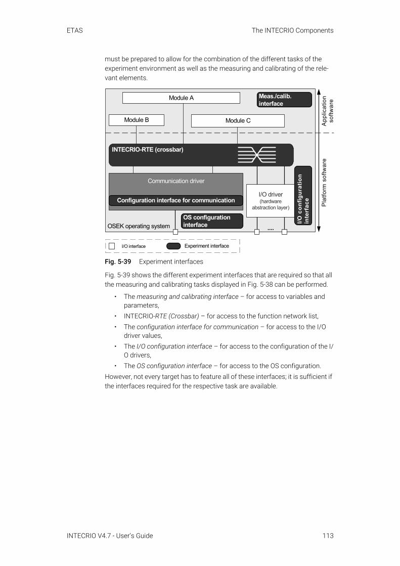
ETAS The INTECRIO Components
must be prepared to allow for the combination of the different tasks of the experiment environment as well as the measuring and calibrating of the rele-vant elements.
Fig. 5-39 Experiment interfaces
Fig. 5-39 shows the different experiment interfaces that are required so that all the measuring and calibrating tasks displayed in Fig. 5-38 can be performed.
• The measuring and calibrating interface – for access to variables and parameters,
• INTECRIO-RTE (Crossbar) – for access to the function network list,• The configuration interface for communication – for access to the I/O
driver values,• The I/O configuration interface – for access to the configuration of the I/
O drivers,• The OS configuration interface – for access to the OS configuration.
However, not every target has to feature all of these interfaces; it is sufficient if the interfaces required for the respective task are available.
I/O interface Experiment interface
OSEK operating system
I/O driver(hardware
abstraction layer)
....
Module B
Module A
Module C
INTECRIO-RTE (crossbar)
Communication driver
Meas./calib.interface
App
licat
ion
softw
are
Pla
tform
sof
twar
e
Configuration interface for communication
I/O c
onfig
urat
ion
inte
rfac
e
OS configurationinterface
INTECRIO V4.7 - User’s Guide 113

ETAS The INTECRIO Components
Real-time targets for rapid prototyping should support all listed interfaces since this type of experiment requires the possibility for quick changes for verifica-tion and validation.
Fig. 5-40 Experiment interfaces for rapid prototyping targets
Fig. 5-40 shows which interface takes on what measuring and calibrating tasks for a rapid prototyping system.
However, for experiments on the production electronic control unit there is no possibility to calibrate the configurations during the running experiment or – except for the real-time behavior of the operating system – to measure. For this reason, only the measuring and calibrating interface as well as the OS configu-ration interface are required, the others can be omitted (see Fig. 5-41).
Fig. 5-41 Experiment interfaces for production electronic control units
OSEK operating system
I/O driver
....
Module B
Module A
Module C
Communication driver
Meas./cal. interface
Configuration interface for communication
I/O c
onfig
urat
ion
inte
rface
OS configuration interface
INTECRIO-RTE (crossbar)
ETAS Experiment Environment
Measuring
INTECRIOOS real-time
behavior
INTECRIOModule variables
INTECRIOFunction network
list - Measurement
INTECRIOI/O driver - Values
Calibrating
INTECRIOModule parameters
INTECRIOFunction network
list - Changes
INTECRIOOS config. - Modifications
INTECRIOI/O driver - Config.
ES800
ES900
ETAS Experiment environment
Measuring
OS real-time behavior
Module variables
Function network list - Measurement
I/O driver - Values
Calibrating
Module parameters
Function network list - Changes
OS-config. - Modifications
I/O driver - Config.
OSEKoperating system
I/O driver
....
Module B
Module A
Module C
Communication driver
Meas./calib. interface
OS configuration interface
Runtime Environment
INTECRIO V4.7 - User’s Guide 114

ETAS The INTECRIO Components
5.10.4 Rapid Prototyping Experiment with the ETAS Experiment EnvironmentIn principle, there are two types of experiments with rapid prototyping systems: bypass and fullpass experiment. The performance of an experiment is roughly the same in both cases; the user wants to execute the prototype, measure val-ues and calibrate parameters. Nevertheless, there are clear differences which are described in the following sections.
5.10.4.1 Bypass ExperimentA bypass experiment exists if only parts of the application software are com-puted on the rapid prototyping hardware.
Bypass experiments are preferably used if only a few software functions must be developed and an electronic control unit with validated software functions – perhaps from a predecessor project – is already available. This electronic con-trol unit then needs to be modified so that it supports a bypass interface. The necessary software modifications with respect to the electronic control unit are referred to as bypass hooks. The effort for creating a bypass experiment is low.
Fig. 5-42 Bypass experiment: Scheme
A bypass system can be considered as a system with two processors: The electronic control unit with bypass link is one processor, the other processor is the rapid prototyping system. The application software (sometimes even a part of the platform software) is distributed to these two processors which are linked with each other by means of a bypass synchronization mechanism (e.g. ETK or CAN bus).
The calculation of the bypass function is generally initiated by the electronic control unit via a control flow interface or trigger; the output values of the bypass function are monitored in the electronic control unit for plausibility. In this case, electronic control unit and rapid prototyping system operate synchro-nously. Alternatively, it is also possible to implement an unsynchronized com-munication without trigger.
OSEK operating system
I/O driver (hardware abstraction
layer)
....
Module B
Module A
Module C
INTECRIO-RTE (crossbar)
Communication driver
ECU with bypass link
ES800
ES900
INTECRIO V4.7 - User’s Guide 115

ETAS The INTECRIO Components
Since the two processors are forming a system, it is necessary that the con-trolling PC views them as one system. This means that access to both proces-sors is assigned by a control application. This is easy to implement by using INCA since INCA allows access to the rapid prototyping target as well as the electronic control unit target.
INTECRIO and the ETAS Experiment Environment support bypass experiments, too. During a bypass experiment with INTECRIO, you can access the experi-mental target from the ETAS Experiment Environment, i.e. you can measure and calibrate the bypass hook variables. However, you have no direct access to the ECU.
Fig. 5-43 Bypass experiments with INTECRIO + ETAS Experiment Environment
5.10.4.2 Fullpass ExperimentIf an electronic control unit with validated software functions and bypass inter-face is not available or if additional sensors and actuators must be validated, fullpass experiments are frequently preferred. The real-time behavior must be guaranteed by the rapid prototyping hardware and possibly monitored; all sen-sor and actuator interfaces required by the function must be supported.
Actu
ator
s
Intelligent I/OSensors
Serial com
munication
INTECRIO + ETAS Experiment Environment
E-Target
ES800ES900
INTECRIO V4.7 - User’s Guide 116

ETAS The INTECRIO Components
The environment of INTECRIO refers to a fullpass experiment if the entire appli-cation software (the control algorithm) runs on the rapid prototyping hardware. The hardware runs in standalone mode (without electronic control unit); the I/O interfaces form the connection to the outside world (see Fig. 5-44); sensors and actuators are directly connected to the hardware.
Fig. 5-44 Fullpass experiment in standalone mode
Fig. 5-45 Fullpass experiment with INTECRIO + ETAS Experiment Environment
The other option consists of using INCA/INCA-EIP instead of the ETAS Experi-ment Environment.
ES1130/ES1135/ES910
OSEK operating system
I/O driver (hardware abstraction
layer)
....
Module B
Module A
Module C
INTECRIO-RTE (crossbar)
Communication driverES1000/ES900I/O interfaces
ES800
ES900
Serial
comm
unicationAct
uato
rs
Sensors Intelligent I/O
INTECRIO + ETAS Experiment Environment
E-Target
ES800ES900
INTECRIO V4.7 - User’s Guide 117

ETAS The INTECRIO Components
5.10.4.3 X-Pass ExperimentThe X-pass experiment is a mixture of bypass and fullpass experiment. The rapid prototyping hardware utilizes the electronic control unit with bypass hooks as interface to the outside world (see Fig. 5-46).
Fig. 5-46 X-pass experiment with electronic control unit as I/O
5.10.5 Virtual Prototyping Experiments with the ETAS Experiment EnvironmentThe ETAS Experiment Environment offers the same options for virtual proto-typing as it does for rapid prototyping, e.g. to view variables and to change parameters. In parallel, this is possible directly in MATLAB and Simulink or in ASCET, as well. In addition, users can change parameters and module connec-tions on the running prototype in order to compare various model configura-tions.
5.11 The DocumentorThe INTECRIO documentor offers the possibility to generate documentation for the components of a system project. The documentation can be generated in HTML or PDF format, and the be printed or used in other documents.
Besides general information on the system project, the documentation file con-tains information on the software and hardware systems and the OS configura-tion. The exact content can be configured; the following specifications are possible:
System Project• general information (INTECRIO version, creation date, etc.)• workspace information• system-level connections (i.e. between hardware and software)
ES1130/ES1135/ES910
OSEK operating system
I/O driver (hardware abstraction
layer)
....
Module B
Module A
Module C
INTECRIO-RTE (Crossbar)
Communication driver
ECU with bypass link
ES800
ES900
INTECRIO V4.7 - User’s Guide 118

ETAS The INTECRIO Components
Software System • information on the software system (general information, signal
sources/sinks of software system and functions, connections on soft-ware system level, etc.)
• information on the contained modules (general information, information regarding module code and files, signal sources/sinks of modules, parameter, processes, etc.)
Environment System • information on the environment system (general information, signal
sources/sinks of environment system and functions, connections on environment system level, etc.)
• information on the contained modules (general information, information regarding module code and files, signal sources/sinks of modules, parameter, processes, etc.)
Hardware System • information on the hardware system (general information, ECU, CPU,
signal sources/sinks of hardware, connections on hardware system level, etc.)
• information on and devices (name, signal groups, signals, etc.)OS Configuration
• general information• information on application modes and tasks• information on OS actions (i.e. processes)• information on events
Details regarding the setup and generation of documentation can be found in the online help.
5.12 RTA-TRACE ConnectivityRTA-TRACE connectivity is an add-on to the ETAS Experiment Environment. It allows for connecting RTA-TRACE with the rapid prototyping hardware or the PC in case of virtual prototyping. By using RTA-TRACE, the time behavior (VP) or the real-time behavior (RP) of the experiment on the target (ES910, ES830, VP-PC) can be displayed.
Additional information about RTA-TRACE and how to operate this tool can be found in the RTA-TRACE documentation.
INTECRIO V4.7 - User’s Guide 119

ETAS SCOOP and SCOOP-IX
6 SCOOP and SCOOP-IXThis chapter contains a concept for the description, management and exchange of C code interfaces. The description and exchange of code inter-faces is a very important topic in the context of INTECRIO since the interfaces for integration are of significant importance.
In the framework of the embedded control software, the smooth integration of simple C code is affected by the fact that certain semantic pieces of informa-tion are not part of the standard C code:
• Implementation data, such as conversion formula, minimum, maximum and limitation for C variables as well as return values and arguments of C functions,
• Grouping information for characteristic values (lookup tables) repre-sented by several C arrays with disjointed definitions or embedded in C structures (struct),
• Information about use that indicate whether an element is intended for measurements or calibration with running experiment, and
• Origin of the model and specific data (e.g. model name, physical unit, embedded component or block, notes, use as message, process, signal or parameter), particularly for automatically generated source files.
Furthermore, additional information is more or less obviously "hidden" in the C code and cannot easily be extracted:
• Memory classes that are written to by non-standard target-specific #pragma instructions, and
• Attributes of C variables or C functions that are written to by non-stan-dard target-specific modifiers such as inline or far.
The concept introduced in this chapter that is used to collect all the necessary interface information and make it available, is referred to as SCOOP (Source Code, Objects, and Physics).
The approach of SCOOP essentially consists of an interface description lan-guage (roughly comparable with known interface description languages such as ARXML1 or that of CORBA2 and COM from Microsoft) and tools for creating, managing and using the interface descriptions.
The interface description language SCOOP-IX (see also section 6.2 "The SCOOP-IX Language" on page 121) is intended for the detailed collection of all the information about interfaces in a wider sense. SCOOP-IX descriptions can be used for the data exchange between tools or supplied together with open or compiled C code for later integration.
1. AUTOSAR XML2. Common Object Request Broker Architecture, developed by the Object Man-
agement Group (OMG, see http://www.omg.org/)
INTECRIO V4.7 - User’s Guide 120

ETAS SCOOP and SCOOP-IX
6.1 The SCOOP ConceptThe approach of SCOOP aims at providing a uniform description of the afore-mentioned information, together with the actual interfaces of the code on C level. Besides the initially mentioned semantic information, a SCOOP-IX inter-face description essentially consists of the following information:
• Name, type and magnitude of C variables• Name, return value and signature of C functions • File origin of C elements
The combination of this information to an interface description language offers a very powerful tool for the following applications:
• Representation of interface inside of INTECRIO and its components, par-ticularly the following:– Experimental target configurator– OS configurator– Project configurator– Project integrator
• Representation of interfaces for communication between different tools and the interfacing of ASCET and MATLAB and Simulink to INTECRIO.
SCOOP provides a formal interface description that is suitable for the following purposes:
• Distribution of object files or libraries together with a comprehensive interface description on the levels of C code, physics and semantics with the support of know-how protection (IP protection).
• Check for compatibility of interfaces of different software modules, not only on the level of C code (name, type, signature), but also on the phys-ical (implementation, unit) and semantic (record layout, use as message or process) level.
• Generation of connection code or wrapper functionality to adjust non-conforming module interfaces to each other for integration.
• To provide tools (such as the OS configurator) with the opportunity of using information further that is transferred by code generators (e.g. all C elements that represent ASCET processes and messages).
6.2 The SCOOP-IX LanguageSCOOP-IX is short for SCOOP Interface Exchange Language; this language is the basis of the SCOOP concept. As mentioned earlier, SCOOP-IX provides means for describing the interfaces of C modules to enable their integration with INTECRIO.
The SCOOP-IX language is based on XML and, therefore, well suited for use in INTECRIO, ASCET, Simulink®, or similar tools.
NOTEINTECRIO V4.7 supports SCOOP-IX versions V1.0, V1.1, V1.2, V1.4, and V1.5.
INTECRIO V4.7 - User’s Guide 121
ETAS SCOOP and SCOOP-IX
6.2.1 Modules and InterfacesSCOOP views a module either as an individual compiling unit (usually a C file) or as a combination of several compiling units (a group of C code or object files, libraries, etc.) with a common interface. Exactly one SCOOP-IX file belongs to a module.
Global C variables as well as C functions can be part of a module interface. If this is the case, they are referred to as interface elements below.
Interface elements are characterized as partners in an access or call relation-ship beyond module boundaries. For this reason, a C declaration or definition is considered to be the correspondence of an interface element of the module in the following cases:
• Export interface: A C variable or C function is globally defined in the mod-ule and available for external linking (not declared as static). The exact definition of the element can be determined directly. Elements that can-not be accessed from outside the module should be omitted from the SCOOP-IX description.
• Import interface: A C variable is accessed from within the module (read, write or address operation) or a C function is called within the module (directly or via address operation), but the element is defined outside of the module. The exact definition of the element can be determined by examining the associated declaration (whose existence is guaranteed with MISRA1 compatibility).
6.2.2 Description of the C Code InterfaceThe description of the C code interface consists of information that is con-tained in the source code. The elements of the code interfaces fall into two categories, variables and functions, and they each contain specific descriptions of the interface elements.
Additional general information about the elements and the modules are also addressed by SCOOP-IX and are described below.
The interface description of a C variable (<dataElement> block, see Page 136, 137, and 138) essentially consists of the following information:
• The name of the variable (<dataCInterface> block, see Page 137, among others)
• The C type of the variable (<type> block, see Page 137, among others)• The number of entries in x (and y) direction if the variable is an array
(matrix)• Information for storage in memory (such as extern, static, const
and volatile, far or huge, #pragma instructions)• An optional initialization value (<initValue> block, see Page 137,
among others)Accordingly, the interface description of a C function (<functionElement> block, see Page 139) essentially consists of the following information:
• Name of the function (<functionCInterface> block, see Page 140)
1. Motor Industry Software Reliability Association
INTECRIO V4.7 - User’s Guide 122
ETAS SCOOP and SCOOP-IX
• Information for storing the function in memory (such as extern and static (general), inline (target-specific), #pragma instructions)
• Arguments and return values of the function, such as: – Names of all arguments– C types of all arguments and the return value (<return> block, see
Page 140)– Information for storage in memory (such as const, far or huge)– Sequence in which the arguments appear
In addition to the specific information described so far about C variables and C functions, general information about each element are important, such as the following:
• Type of interface element (import vs. export; interfaceKind parame-ter, see Page 137 and Page 139),
• File origin (<fileOrigin> block, see Page 137 and Page 140)Each module interface is described not only by its elements, but also by the following general information:
• File origin of elements (<fileContainer> block, see Page 136).• C header files to be integrated (also <fileContainer> block).• Status of the module (source code, object file or library;
<constitution> block and mode parameter, see Page 135).• Hardware target (<target> block, see Page 135) and compiler
(<tool> block, see Page 135) that the module requires.• Compiler options and similar settings that were used for the creation or
must be used for further processing (<configuration> block, see Page 135).
6.2.3 Description of Semantic InformationIn contrast to the information about the C code interface, semantic information cannot be extracted from source code through analysis. Instead, this type of interface information must be created manually or automatically by a code generator together with the actual code generation. ASCET and MATLAB and Simulink connectivity offer the latter option.
Semantic information about elements is divided into the categories "Model Ori-gin" , "Implementation" and "Use" . These categories are explained in the follow-ing sections. Additional module-specific information is also considered (see “Module Data” on page 126).
6.2.3.1 Model OriginIf the C source code described was automatically generated or manually cre-ated from a more or less formal model (such as block diagram, state machine, control or data flow diagram), the origin of each interface element can be described in the model.
The model origin is used primarily for documentation purposes and for improved orientation of the user. Configuration tools, such as the project con-figurator, can display this information, thereby providing the user a means for identifying model elements.
INTECRIO V4.7 - User’s Guide 123

ETAS SCOOP and SCOOP-IX
In addition, the information about the model origin can be used to forward spe-cific information to other tools. For example, if ASCET marks the C elements that were generated for processes and messages, it allows the OS configurator to locate precisely these elements out of the entire interface description and to present to the user as possible candidates for the configuration of the operat-ing system.
In addition to that, the description of the origin allows for enabling semantic checks in the model at the highest level with respect to consistency or plausi-bility across domain and tool boundaries.
Information about the model origin are divided into general and model-specific information. The latter are explained using examples of ASCET and MATLAB and Simulink.
General information about the model origin (<modelOrigin> block, see Page 138 and Page 140) can consist of the following elements:
• A model name such as the displayed name of the interface element (<name> block, see Page 138 and Page 140) or the element name of a memory element, signal, method, etc.
• A unique identifier in the model (identifier option, see Page 138 and Page 140)
• A model path within a hierarchical model structure (<modelLink> block, see Page 138 and Page 140)
• Model type such as continuous, discrete, Boolean, array, etc. for C variables, return values and arguments of functions (<modelType> block, see Page 138)
• Model form such as variable, parameter or constant for C variables (<modelKind> block, kind option, see Page 138 and Page 140)
• Visibility in other models, either public or private (visibility option, see Page 138 and Page 140)public visibility corresponds to the ASCET scope exported,private visibility corresponds to the ASCET scope local.
• Logical flow direction for C variables, such as input port or output port (<flowDirection> block, see Page 137)
• Physical unit for C variables, return values and arguments of functions• Value range on the model level for C variables, return values and argu-
ments of functions• Textual notes, such as user comments, additional non-specific model
information, etc. (<annotation> block, see Page 138 and Page 140)Depending on the BMT used, certain domain-specific information is important for the integration of SCOOP-IX modules.
The following information is of special interest for code that was generated with ASCET:
• The ASCET component in which the equivalent of the respective inter-face element is embedded
• The type of component (class, module or project; <pathNode> block with kind="asd:module" option, see Page 138)
INTECRIO V4.7 - User’s Guide 124

ETAS SCOOP and SCOOP-IX
• The type of equivalent of the interface element (element, message, resource, method, process, task; <pathNode> block with kind="asd:element" option, see Page 138)
In real-time operating systems, such as ERCOSEK, processes on C code level are represented by means of void/void functions. With respect to the OS configuration and project integration, the following information is of interest, among others:
• Messages that are accessed within the process or any C function that is called inside of them (<messageAccess> block, see Page 140), as well as the respective access mode (send, receive; send option, see Page 140).
• Resources that are accessed within the process or any C function that is called inside of them (<resourceAccess> block, see Page 140).
• Time requirements on the model level (<constraint> block, see Page 140), such as – Period (<period> block, see Page 140), offset, deadline and priority
(priority option, see Page 140) of the execution, – Type of trigger (initialization, timer, interrupt or software; trigger
option, see Page 140) and – Scheduling mode (preemptive, cooperative or non-preemptable;
<scheduling> block, see Page 140).Since the actual priority levels are dependent upon the operating system and the CPU, imprecise priorities such as background, low, normal, high and scheduler are allowed.
The following information is of special interest for code that was generated with MATLAB and Simulink:
• MATLAB and Simulink subsystem or block that contains the counterpart to the respective interface element, as well as the type of subsystem or block.
• Type of counterpart to the interface element (signal or parameter).The scan rates of a MATLAB and Simulink model can be formulated by means of comparable time restrictions such as the aforementioned ones.
6.2.3.2 ImplementationTo allow for data consistency checks and the generation of connection code, information about the implementations of the C code interfaces is required. This applies to C variables, return values and arguments of functions.
Implementation information (<implementation> block, see Page 138) is comprised of
• A conversion formula that describes the relationship between the data of a model element and those of its C code equivalent (<conversion> block, see Page 136, and <conversionRef> block, see Page 138),
• Minimum and maximum values on the C code level (<valueRange> block, see Page 138) and
INTECRIO V4.7 - User’s Guide 125

ETAS SCOOP and SCOOP-IX
• The use of ASCET limiters and (in SCOOP-IX V1.2) resolution scheme if the boundaries of the value range are exceeded (<saturation> block, see Page 138).The <saturation> block contains the options value, resolution and assignment. Depending on the settings in the ASCET implementa-tion editor, the options are set as follows.– value is set to true (false) if Limit to maximum bit length is acti-
vated (deactivated)– resolution is set to automatic, keep, or reduce, depending on
the selection in the combo box next to Limit to maximum bit length.– assignment is set to true (false) if Limit Assignments is acti-
vated (deactivated).For Simulink models, or for ASCET variables that use no limiter, the <saturation> block is omitted.
• For SCOOP-IX files generated with ASCET V6.4: The <zeroExcluded> block (see Page 138) always contains value="false".For SCOOP-IX files generated with ASCET V5.0 - V6.3: The <zeroExcluded> block contains information whether zero is explicitly excluded from the interval.
6.2.3.3 UseThe following semantic information about the use of interface elements is important (only data elements):
• The relationship between characteristic values and the respective C variables from which they are formed, as well as information about the characteristic value, such as axes, dimensions and record layout
• Use for measurement or calibration: <usage> block, see Page 138 (measurement) or Page 139 (calibration)
• Pseudo addresses for the simulation interface to the experimental target or ECU addresses with the corresponding bit masks
6.2.3.4 Module DataThe following add-on information may be contained in the SCOOP-IX descrip-tion of a module (<moduleInfo> block, see Page 133):
• Module name (<name> block, see Page 133)• The module version concerning the contents of the interface description
(<version> block, see Page 133)• Date and time of the creation (<dateTime> block with the
kind="created" option, see Page 133)• Date and time of the last modification (<dateTime> block with the
kind="lastModified" option, see Page 133)• Degree of completion of the interface description (<completion>
block, see Page 133), i.e. one of the following statuses:– basic (only pure C code interface data, no semantic information)– in progress (intermediate format, semantic information partially
completed)– full (document is considered to be stable, semantic information
not compulsorily complete)
INTECRIO V4.7 - User’s Guide 126
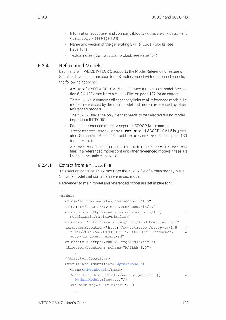
ETAS SCOOP and SCOOP-IX
• Information about user and company (blocks <company>, <user> and <creators>, see Page 134)
• Name and version of the generating BMT (<tool> blocks, see Page 134)
• Textual notes (<annotation> block, see Page 134)
6.2.4 Referenced ModelsBeginning withV4.7.3, INTECRIO supports the Model Referencing feature of Simulink. If you generate code for a Simulink model with referenced models, the following happens:
• A *.six file of SCOOP-IX V1.5 is generated for the main model. See sec-tion 6.2.4.1 "Extract from a *.six File" on page 127 for an extract.This *.six file contains all necessary links to all referenced models, i.e. models referenced by the main model and models referenced by other referenced models. The *.six file is the only file that needs to be selected during model import into INTECRIO.
• For each referenced model, a separate SCOOP-IX file named <referenced_model_name>.ref_six of SCOOP-IX V1.5 is gener-ated. See section 6.2.4.2 "Extract from a *.ref_six File" on page 130 for an extract.A *.ref_six file does not contain links to other *.six or *.ref_six files. If a referenced model contains other referenced models, these are linked in the main *.six file.
6.2.4.1 Extract from a *.six FileThis section contains an extract from the *.six file of a main model, in.e. a Simulink model that contains a referenced model.
References to main model and referenced model are set in blue font.
...<module
xmlns="http://www.etas.com/scoop-ix/1.5" xmlns:ix="http://www.etas.com/scoop-ix/1.5" xmlns:mlsl="http://www.etas.com/scoop-ix/1.5/ ↵
modelDomain/matlab-simulink" xmlns:xsi="http://www.w3.org/2001/XMLSchema-instance"xsi:schemaLocation="http://www.etas.com/scoop-ix/1.5 ↵
file://C:\ETAS\INTECRIO4.7\SCOOP-IX\1.2/schemas/ ↵scoop-ix-domain-mlsl.xsd"
xmlns:html="http://www.w3.org/1999/xhtml"><directoryLocations scheme="MATLAB 9.3">
...</directoryLocations><moduleInfo identifier="MyMainModel">
<name>MyMainModel</name><modelLink href="mlsl://"{{modelDir}} ↵
MyMainModel.slx""/><version major="1" minor="9"/>...
INTECRIO V4.7 - User’s Guide 127

ETAS SCOOP and SCOOP-IX
<creators><user lastName="MOL9FE" role="creator"/><tool kind="environment" vendor="The Mathworks, ↵
Inc." name="MATLAB">...
</tool><tool kind="modeler" vendor="The Mathworks, Inc." ↵
name="Simulink">...
</tool><tool kind="modeler" vendor="The Mathworks, Inc." ↵
name="Stateflow"></tool><tool kind="codeGenerator" vendor="The Mathworks, ↵
Inc." name="Simulink Coder">...
</tool><tool kind="codeGenerator" vendor="The Mathworks, ↵
Inc." name="MATLAB Coder">...
</tool><tool kind="codeGenerator" vendor="ETAS GmbH" ↵
name="Connector for Simulink (IRT)" ↵family="INTECRIO Tool Suite"><version major="4" minor="7" year="2019" ↵
month="1" day="1"/><configuration>
<option identifier="SCOOPIXFileName"> ↵<![CDATA[MyMainModel.six]]></option>
...</configuration>
</tool></creators>
</moduleInfo><codeInfo>
<constitution mode="sourceCode"/><dateTime kind="created" year="2019" month="5" ↵
day="16" hour="11" minute="20" second="37"/><target>
<board vendor="ETAS GmbH" model="INTECRIO ↵Generic Experimental Target"/>
<tool kind="compiler" vendor="GNU Project" ↵family="GNU Compiler Collection" ↵name="GNU C Compiler"><configuration>
<optionKind name="macroDefine" prefix="-D"/><optionKind name="includeDirectory" ↵
prefix="-I"/><!-- RTW specific defines --><option kind="macroDefine" name="USE_RTMODEL"/>
INTECRIO V4.7 - User’s Guide 128

ETAS SCOOP and SCOOP-IX
<option kind="macroDefine" name="MODEL"> ↵MyMainModel</option>
...<!-- RTW specific include directories --><option kind="includeDirectory"> ↵
<![CDATA[{{codeDir}}]]></option>...<!-- S-Function specific include directories --><!-- Referenced models local include
directory --><option kind="includeDirectory"> ↵
<![CDATA[{{codeDir}} ↵referenced_model_includes]]></option>
</configuration></tool>
</target></codeInfo><!-- Model specific files --><fileContainer constitution="sourceCode">
<pathBase path="{{codeDir}}"/><!-- Model specific source files --><file name="MyMainModel_types.h" kind="header"/><file name="MyMainModel.h" kind="header"/><!-- used through rtwShared.lib: ↵
zero_crossing_types.h --><file name="MyMainModel.c" kind="body"/><file name="MyMainModel_private.h" kind="header"/><file name="rtmodel.h" kind="header"/><!-- used through rtwShared.lib: rtGetInf.h --><!-- used through rtwShared.lib: rtGetInf.c --><!-- used through rtwShared.lib: rtGetNaN.h --><!-- used through rtwShared.lib: rtGetNaN.c --><file name="MyMainModel_main.c" kind="body"/><!-- Additionally registered model specific source
files --><file name="rt_sim.c" ↵
path="{{codeDir}}external\rtw\c\src\" kind="body"/><!-- Target specific libraries --><file name="rtwStaticLib.lib" kind="symbolicLibrary"/><file name="rtwSharedLib.lib" kind="symbolicLibrary"/><!-- Additional files -->
</fileContainer><fileContainer constitution="referencedModels">
<!-- SCOOP-IX files for referenced models --> <file name="MySub.ref_six" ↵
path="D:\ETASData\INTECRIO4.7\User\ModelRef\ ↵modules\mysub\" kind="SIX" format="SCOOP-IX"/>
</fileContainer>...
INTECRIO V4.7 - User’s Guide 129

ETAS SCOOP and SCOOP-IX
6.2.4.2 Extract from a *.ref_six FileThis section contains an extract from the *.ref_six file of a referenced model.
References to the model described in *.ref_six are set in blue font.
...<module
xmlns="http://www.etas.com/scoop-ix/1.5" xmlns:ix="http://www.etas.com/scoop-ix/1.5"xmlns:mlsl="http://www.etas.com/scoop-ix/1.5/ ↵
modelDomain/matlab-simulink"xmlns:xsi="http://www.w3.org/2001/XMLSchema-instance" xsi:schemaLocation="http://www.etas.com/scoop-ix/1.5 ↵
file://C:\ETAS\INTECRIO4.7\SCOOP-IX\1.2/schemas/ ↵scoop-ix-domain-mlsl.xsd"
xmlns:html="http://www.w3.org/1999/xhtml"><directoryLocations scheme="MATLAB 9.3">
...</directoryLocations><moduleInfo identifier="MySub">
<name>MySub</name><modelLink ↵
href="mlsl://"{{modelDir}}MySub.slx""/><version major="1" minor="26"/>...<creators>
<user lastName="MOL9FE" role="creator"/><tool kind="environment" vendor="The Mathworks, ↵
Inc." name="MATLAB">...
</tool><tool kind="modeler" vendor="The Mathworks, Inc." ↵
name="Simulink">...
</tool><tool kind="modeler" vendor="The Mathworks, Inc." ↵
name="Stateflow"></tool><tool kind="codeGenerator" vendor="The Mathworks, ↵
Inc." name="Simulink Coder">...
</tool>
NOTEThe <fileContainer constitution="referencedModels"> sec-tion in the *.six file of a main model contains links to all referenced models, i.e. models referenced by the main model and models referenced by other referenced models.
INTECRIO V4.7 - User’s Guide 130
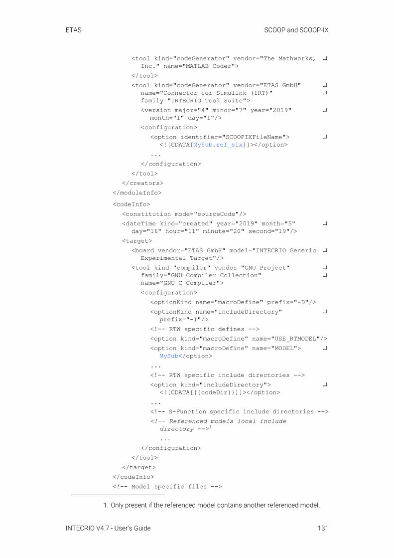
ETAS SCOOP and SCOOP-IX
<tool kind="codeGenerator" vendor="The Mathworks, ↵Inc." name="MATLAB Coder">
</tool><tool kind="codeGenerator" vendor="ETAS GmbH" ↵
name="Connector for Simulink (IRT)" ↵family="INTECRIO Tool Suite"><version major="4" minor="7" year="2019" ↵
month="1" day="1"/><configuration>
<option identifier="SCOOPIXFileName"> ↵<![CDATA[MySub.ref_six]]></option>
...</configuration>
</tool></creators>
</moduleInfo><codeInfo>
<constitution mode="sourceCode"/><dateTime kind="created" year="2019" month="5" ↵
day="16" hour="11" minute="20" second="19"/><target>
<board vendor="ETAS GmbH" model="INTECRIO Generic ↵Experimental Target"/>
<tool kind="compiler" vendor="GNU Project" ↵family="GNU Compiler Collection" ↵name="GNU C Compiler"><configuration>
<optionKind name="macroDefine" prefix="-D"/><optionKind name="includeDirectory" ↵
prefix="-I"/><!-- RTW specific defines --><option kind="macroDefine" name="USE_RTMODEL"/><option kind="macroDefine" name="MODEL"> ↵
MySub</option>...<!-- RTW specific include directories --><option kind="includeDirectory"> ↵
<![CDATA[{{codeDir}}]]></option>...<!-- S-Function specific include directories --><!-- Referenced models local include
directory -->1
...</configuration>
</tool></target>
</codeInfo><!-- Model specific files -->
1. Only present if the referenced model contains another referenced model.
INTECRIO V4.7 - User’s Guide 131
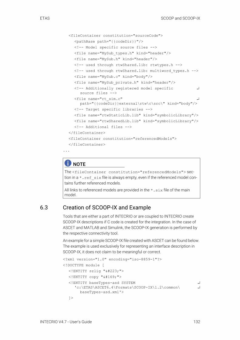
ETAS SCOOP and SCOOP-IX
<fileContainer constitution="sourceCode"><pathBase path="{{codeDir}}"/><!-- Model specific source files --><file name="MySub_types.h" kind="header"/><file name="MySub.h" kind="header"/><!-- used through rtwShared.lib: rtwtypes.h --><!-- used through rtwShared.lib: multiword_types.h --><file name="MySub.c" kind="body"/><file name="MySub_private.h" kind="header"/><!-- Additionally registered model specific ↵
source files --><file name="rt_sim.c" ↵
path="{{codeDir}}external\rtw\c\src\" kind="body"/><!-- Target specific libraries --><file name="rtwStaticLib.lib" kind="symbolicLibrary"/><file name="rtwSharedLib.lib" kind="symbolicLibrary"/><!-- Additional files -->
</fileContainer><fileContainer constitution="referencedModels"></fileContainer>
...
6.3 Creation of SCOOP-IX and ExampleTools that are either a part of INTECRIO or are coupled to INTECRIO create SCOOP-IX descriptions if C code is created for the integration. In the case of ASCET and MATLAB and Simulink, the SCOOP-IX generation is performed by the respective connectivity tool.
An example for a simple SCOOP-IX file created with ASCET can be found below. The example is used exclusively for representing an interface description in SCOOP-IX, it does not claim to be meaningful or correct.
<?xml version="1.0" encoding="iso-8859-1"?><!DOCTYPE module [
<!ENTITY szlig "ß"><!ENTITY copy "©"><!ENTITY baseTypes-asd SYSTEM ↵
'c:\ETAS\ASCET6.4\Formats\SCOOP-IX\1.2\common\ ↵baseTypes-asd.xml'>
]>
NOTEThe <fileContainer constitution="referencedModels"> sec-tion in a *.ref_six file is always empty, even if the referenced model con-tains further referenced models.
All links to referenced models are provided in the *.six file of the main model.
INTECRIO V4.7 - User’s Guide 132
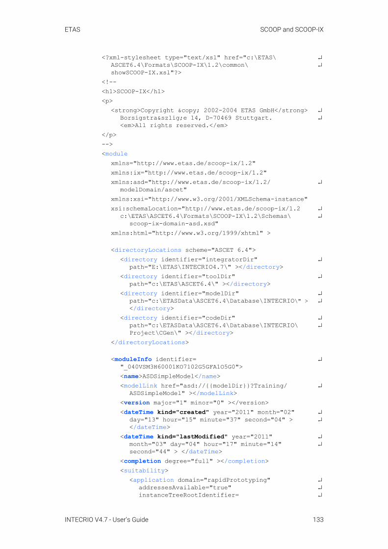
ETAS SCOOP and SCOOP-IX
<?xml-stylesheet type="text/xsl" href="c:\ETAS\ ↵ASCET6.4\Formats\SCOOP-IX\1.2\common\ ↵showSCOOP-IX.xsl"?>
<!--<h1>SCOOP-IX</h1><p>
<strong>Copyright © 2002-2004 ETAS GmbH</strong> ↵Borsigstraße 14, D-70469 Stuttgart. ↵<em>All rights reserved.</em>
</p>--><module
xmlns="http://www.etas.de/scoop-ix/1.2" xmlns:ix="http://www.etas.de/scoop-ix/1.2" xmlns:asd="http://www.etas.de/scoop-ix/1.2/ ↵
modelDomain/ascet" xmlns:xsi="http://www.w3.org/2001/XMLSchema-instance" xsi:schemaLocation="http://www.etas.de/scoop-ix/1.2 ↵
c:\ETAS\ASCET6.4\Formats\SCOOP-IX\1.2\Schemas\ ↵scoop-ix-domain-asd.xsd"
xmlns:html="http://www.w3.org/1999/xhtml" >
<directoryLocations scheme="ASCET 6.4"><directory identifier="integratorDir" ↵
path="E:\ETAS\INTECRIO4.7\" ></directory><directory identifier="toolDir" ↵
path="c:\ETAS\ASCET6.4\" ></directory><directory identifier="modelDir" ↵
path="c:\ETASData\ASCET6.4\Database\INTECRIO\" > ↵</directory>
<directory identifier="codeDir" ↵path="c:\ETASData\ASCET6.4\Database\INTECRIO\ ↵Project\CGen\" ></directory>
</directoryLocations>
<moduleInfo identifier= ↵"_040VSM3H60001KO7102G5GFA1O5G0"><name>ASDSimpleModel</name><modelLink href="asd://{{modelDir}}?Training/ ↵
ASDSimpleModel" ></modelLink><version major="1" minor="0" ></version><dateTime kind="created" year="2011" month="02" ↵
day="13" hour="15" minute="37" second="04" > ↵</dateTime>
<dateTime kind="lastModified" year="2011" ↵month="03" day="04" hour="17" minute="14" ↵second="44" > </dateTime>
<completion degree="full" ></completion><suitability>
<application domain="rapidPrototyping" ↵addressesAvailable="true" ↵instanceTreeRootIdentifier= ↵
INTECRIO V4.7 - User’s Guide 133

ETAS SCOOP and SCOOP-IX
"_040VSM3H60001KO7102G5GFA1O5G0instance" ↵setGetDeltaTIdentifier= ↵
"__040VSM3H60001KO7102G5GFA1O5G0"> ↵</application>
</suitability><company name="ETAS GmbH" department="ETAS/PAC-F1" ↵
city="Stuttgart" country="Germany" /><user lastName="Doe" firstName="John" title="Dr" > ↵
</user><creators>
<user lastName="Doe" firstName="John" ↵title="Dr" ></user>
<tool kind="modeler" vendor="ETAS GmbH" ↵name="ASCET"><version major="6" minor="1" revision="1" > ↵
</version><configuration >
<option identifier="ignoreInternalMessages" ↵> false</option>
</configuration></tool><tool kind="codeGenerator" vendor="ETAS GmbH" ↵
name="ASCET"><version major="6" minor="1" revision="1" > ↵
</version><mode name="experiment" ↵
value="Implementation" ></mode><configuration>
<option identifier="Code Generator" > ↵Implementation Experiment</option>
<option identifier="Target" >Prototyping ↵</option>
...1</configuration>
</tool></creators><annotation>
<ix:documentation xmlns="http://www.w3.org/ ↵1999/xhtml"><p>This is a sample module interface ↵
description file. It is used for ↵demonstrating an interface
description in the <b>SCOOP-IX</b> ↵language.</p>
<p>Neither is its content supposed to make ↵any sense at all, nor has its correctness ↵been checked by compilation.</p>
</ix:documentation></annotation>
1. A SCOOP-IX file contains all settings from the project properties. For docu-mentation purposes, only the first two are listed.
INTECRIO V4.7 - User’s Guide 134
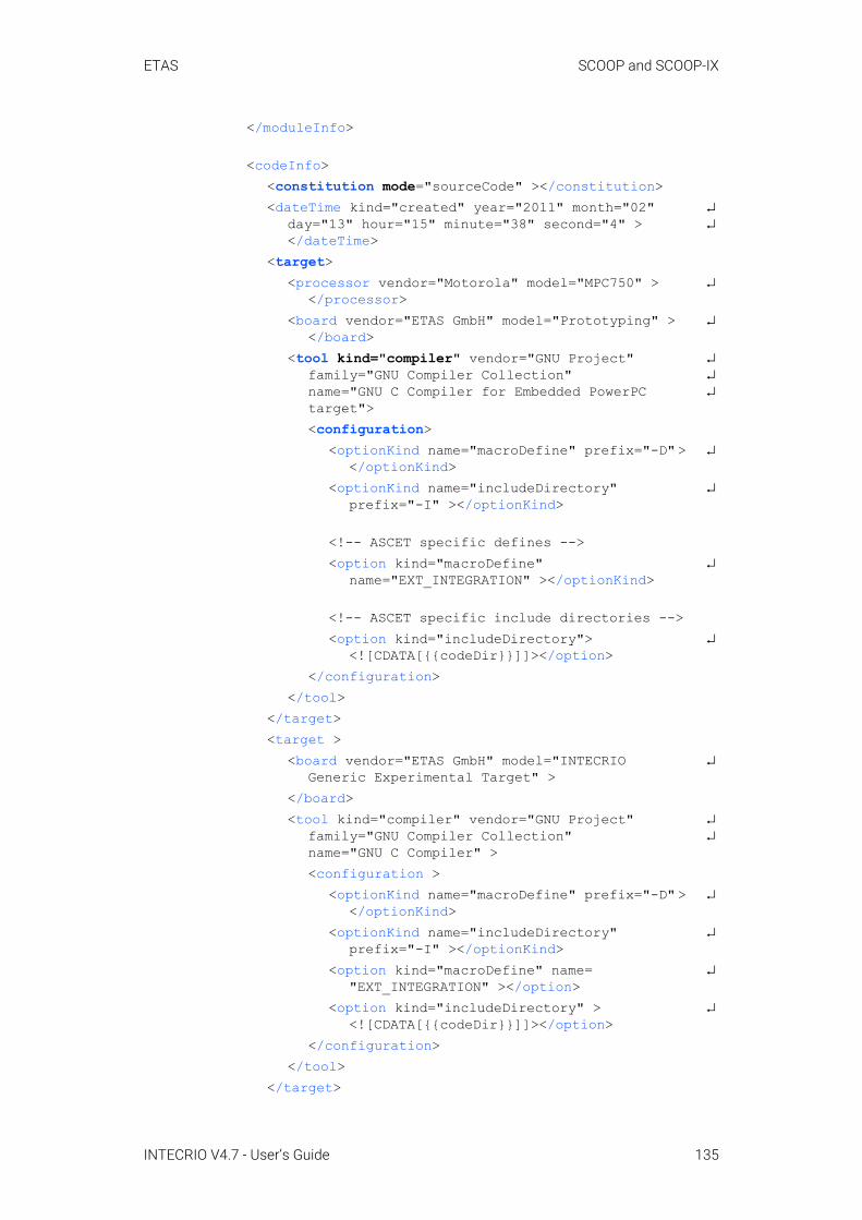
ETAS SCOOP and SCOOP-IX
</moduleInfo>
<codeInfo><constitution mode="sourceCode" ></constitution><dateTime kind="created" year="2011" month="02" ↵
day="13" hour="15" minute="38" second="4" > ↵</dateTime>
<target><processor vendor="Motorola" model="MPC750" > ↵
</processor><board vendor="ETAS GmbH" model="Prototyping" > ↵
</board><tool kind="compiler" vendor="GNU Project" ↵
family="GNU Compiler Collection" ↵name="GNU C Compiler for Embedded PowerPC ↵target"><configuration>
<optionKind name="macroDefine" prefix="-D" > ↵</optionKind>
<optionKind name="includeDirectory" ↵prefix="-I" ></optionKind>
<!-- ASCET specific defines --><option kind="macroDefine" ↵
name="EXT_INTEGRATION" ></optionKind>
<!-- ASCET specific include directories --><option kind="includeDirectory"> ↵
<![CDATA[{{codeDir}}]]></option></configuration>
</tool></target><target >
<board vendor="ETAS GmbH" model="INTECRIO ↵Generic Experimental Target" >
</board><tool kind="compiler" vendor="GNU Project" ↵
family="GNU Compiler Collection" ↵name="GNU C Compiler" ><configuration >
<optionKind name="macroDefine" prefix="-D" > ↵</optionKind>
<optionKind name="includeDirectory" ↵prefix="-I" ></optionKind>
<option kind="macroDefine" name= ↵"EXT_INTEGRATION" ></option>
<option kind="includeDirectory" > ↵<![CDATA[{{codeDir}}]]></option>
</configuration></tool>
</target>
INTECRIO V4.7 - User’s Guide 135

ETAS SCOOP and SCOOP-IX
</codeInfo>
<fileContainer complete="false"><pathBase path="{{codeDir}}" ></pathBase><!-- model specific C files --><file name="_asd_pid.c" kind="body" ></file><file name="asdsmpm.c" kind="body" ></file><file name="conf.c" kind="body" ></file><file name="modulem.c" kind="body" ></file><file name="asdsmpm.h" kind="header" ></file><file name="conf.h" kind="header" ></file><file name="modulem.h" kind="header" ></file><!-- additional files --><file name="ASDSimpleModel.a2l"
content="dataDescription" format="ASAM-2MC" ↵formatVersion="1.5" ></file>
</fileContainer>
<interface><modelLinkBase href="asd://
{{modelDir}}?Training/ASDSimpleModel/" > ↵</modelLinkBase>
<pathBase path="{{codeDir}}" ></pathBase><headerFile name="asdsmpm.h" ></headerFile><headerFile name="conf.h" ></headerFile><headerFile name="modulem.h" ></headerFile><usage layoutFamily="asd:standardLayout" ></usage>&baseTypes-asd;
<definitions><conversion name="ident">
<rationalFunction><numerator bx="1" ></numerator><denominator f="1" ></denominator>
</rationalFunction></conversion>
</definitions>
<dataElement interfaceKind="export"><dataCInterface identifier= ↵
"MODULE_IMPL_ClassObj.Out1->val"><type><typeRef name="real64" ></typeRef></type><fileOrigin name="MODULEM.c" ></fileOrigin><initValue value="0.0" ></initValue>
</dataCInterface><modelOrigin identifier="ASDSimpleModel. ↵
Module.Out1"><name>Out1</name>
INTECRIO V4.7 - User’s Guide 136
ETAS SCOOP and SCOOP-IX
<modelLink href="Module.Out1" ></modelLink><modelLocation>
<pathNode name="Module" kind="asd:module"><pathParameter name="asd:implementation" ↵
value="Impl" ></pathParameter><pathParameter name="asd:dataSet" ↵
value="Data" ></pathParameter></pathNode><pathNode name="Out1" kind="asd:element" > ↵
</pathNode></modelLocation><modelKind kind="message" visibility="public">
<flowDirection in="false" out="true" > ↵</flowDirection>
</modelKind><modelType type="continuous" ></modelType><annotation>
<ix:documentation xmlns= ↵"http://www.w3.org/1999/xhtml" ↵lang="en-US">This is output message <i>Out1</i> of ↵
continuous type.</ix:documentation>
</annotation></modelOrigin><implementation>
<conversionRef name="ident" ></conversionRef><valueRange min="-2147483648" ↵
max="2147483647" ></valueRange><saturation value="true" resolution="reduce" ↵
assignment="true" ></saturation><zeroExcluded value="false" ></zeroExcluded>
</implementation><usage measurement="true" virtual="false" ↵
variant="false" ><address kind="pseudo" >
<BLOB kind="KP_BLOB" device="E_TARGET" > ↵<![CDATA[2 1001 1 1001 1]]></BLOB>
</address></usage>
</dataElement>
<dataElement interfaceKind="export"><dataCInterface identifier= ↵
"ASDSIMPLEMODEL_IMPL_ClassObj.Module-> ↵myProduct->val"><type><typeRef name="sint32" ></typeRef></type><fileOrigin name="MODULEM.c" ></fileOrigin><initValue value="0" ></initValue>
</dataCInterface>
INTECRIO V4.7 - User’s Guide 137

ETAS SCOOP and SCOOP-IX
<modelOrigin identifier="ASDSimpleModel.Module.myProduct"><name>myProduct</name><modelLink href="ASDSimpleModel.Module. ↵
myProduct" ></modelLink><modelLocation>
<pathNode name="Module" kind="asd:module"><pathParameter name="asd:implementation" ↵
value="Impl" ></pathParameter><pathParameter name="asd:dataSet" ↵
value="Data" ></pathParameter></pathNode><pathNode name="myProduct" ↵
kind="asd:element" ></pathNode></modelLocation><modelKind kind="variable" ↵
visibility="private" ></modelKind><modelType type="continuous" >
<valueRange min="-2147483648.0" ↵max="2147483647.0" ></valueRange>
</modelType><annotation>
<ix:documentation xmlns= ↵"http://www.w3.org/1999/xhtml" ↵lang="en-US">This is variable <i>myProduct</i> of ↵
continuous type.</ix:documentation>
</annotation></modelOrigin><implementation>
<conversionRef name="ident" ></conversionRef><valueRange min="-2147483648" ↵
max="2147483647"> </valueRange><saturation value="true" resolution="reduce" ↵
assignment="true" ></saturation><zeroExcluded value="false" ></zeroExcluded>
</implementation><usage measurement="true" virtual="false" ↵
variant="false" ><address kind="pseudo" >
<BLOB kind="KP_BLOB" device="E_TARGET" > ↵<![CDATA[2 1001 1 1000 0]]></BLOB>
</address></usage>
</dataElement>
<dataElement interfaceKind="export"><dataCInterface identifier= ↵
"ASDSIMPLEMODEL_IMPL_ClassObj.Module-> ↵myPar->val">
INTECRIO V4.7 - User’s Guide 138

ETAS SCOOP and SCOOP-IX
<type><typeRef name="real64" ></typeRef></type><fileOrigin name="MODULEM.c" lines="23" > ↵
</fileOrigin><initValue value="3.2" />
</dataCInterface><modelOrigin identifier="ASDSimpleModel. ↵
Module.myPar"><name>myPar</name><modelLink href="ASDSimpleModel.Module.myPar" ↵
> </modelLink> ↵<modelLocation>
<pathNode name="Module" kind="asd:module"><pathParameter name=
"asd:implementation" value="Impl" > ↵</pathParameter>
<pathParameter name= ↵"asd:dataSet" value="Data" > ↵</pathParameter>
</pathNode><pathNode name="myPar"
kind="asd:element" ></pathNode></modelLocation><modelKind kind="parameter" ↵
visibility="private" ></modelKind><modelType type="continuous" ></modelType><annotation>
<ix:documentation xmlns= ↵"http://www.w3.org/1999/xhtml" ↵lang="en-US">This is parameter <i>myPar</i> of ↵
continuous type.</ix:documentation>
</annotation></modelOrigin><implementation>
<conversionRef name="ident" ></conversionRef><valueRange min="-1.e+037" max="1.e+037" > ↵
</valueRange><zeroExcluded value="false" ></zeroExcluded>
</implementation><usage calibration="true" virtual="false" ↵
variant="false" ><address kind="pseudo" >
<BLOB kind="KP_BLOB" device="E_TARGET" ↵><![CDATA[2 1001 1 1000 1]]></BLOB>
</address></usage>
</dataElement>
<functionElement interfaceKind="export">
INTECRIO V4.7 - User’s Guide 139
ETAS SCOOP and SCOOP-IX
<functionCInterface identifier= ↵"MODULE_IMPL_compute"><signature>
<return><type><void /></type>
</return><void />
</signature><fileOrigin name="MODULEM.c" ></fileOrigin>
</functionCInterface><modelOrigin identifier="Module.compute">
<name>compute</name><modelLink href="Module.compute" /><modelLocation>
<pathNode name="Module" kind="asd:module"><pathParameter name="asd:implementation" ↵
value="Impl" ></pathParameter><pathParameter name="asd:dataSet"
value="Data" ></pathParameter></pathNode><pathNode name="compute" kind="asd:process" >
</pathNode></modelLocation><modelKind kind="process" ↵
visibility="public" > </modelKind><runTimeInfo>
<FPUUsage value="true" ></FPUUsage><TerminateTaskUsage value="false" > ↵
</TerminateTaskUsage><messageAccess>
<message identifier= ↵"MODULE_IMPL_ClassObj.Out1->val" ↵send="true" ></message>
</messageAccess><resourceAccess ></resourceAccess><constraint>
<period value="0.01" ></period><execution trigger="timer" priority="0" > ↵
</execution><scheduling mode="preemptive" > ↵
</scheduling></constraint>
</runTimeInfo><annotation>
<ix:documentation xmlns= ↵"http://www.w3.org/1999/xhtml">This is process <i>compute</i> of module ↵
<i>Module</i>.</ix:documentation>
</annotation>
INTECRIO V4.7 - User’s Guide 140

ETAS SCOOP and SCOOP-IX
</modelOrigin></functionElement>
</interface></module>
INTECRIO V4.7 - User’s Guide 141

ETAS Modeling Hints
7 Modeling HintsThis chapter provides an overview of the modeling philosophy of INTECRIO and describes how the behavioral modeling tools are used in conjunction with INTECRIO.
This chapter does not intend to provide the complete instructions for creating an effective executable model.
7.1 Modeling for INTECRIOIf you create a model to be integrated with INTECRIO, the model itself does not contain any target-dependent information. The configuration of the operating system and the hardware configuration (e.g. assignment of processes to tasks or mapping of signals to a CAN frame) are performed with INTECRIO.
A software module is the unit that can be imported in INTECRIO. It corresponds exactly to one SCOOP-IX description. In Simulink, this unit is a complete model that can contain any number of subsystems. As a special case, you can also generate code for a subsystem. This is treated as if it were a complete model. In ASCET, a complete project is considered to be the unit that can be imported. It can contain any number of classes and modules.
Several models can be imported in INTECRIO as software modules. The inputs and outputs can be connected with each other and with physical I/O systems. These connections can be changed dynamically, i.e. during the running experi-ment. A limitation is that these connections must be scalar. Vector connections can be measured as a whole, but only connected element by element in INTEC-RIO.
Several software modules with their connections, a hardware system and an OS configuration form a system project – the unit for which INTECRIO can gen-erate executable code (an *.a2l.cod file).
7.2 Modeling with SimulinkMATLAB and Simulink connectivity (see section 5.1) supports MATLAB® and Simulink® with versions R2014a – R2020a (both 32 bit (≤ R2015b) and 64 bit) and their related service packs known at the time of the INTECRIO V4.7 release.
Unsupported MATLAB and Simulink versions cannot be used to create code for use with INTECRIO.
Model code created with MATLAB and Simulink R2006b – R2013b can still be imported and integrated in INTECRIO V4.7.
During the installation of MATLAB and Simulink connectivity, the MATLAB and Simulink installation is adjusted so that MATLAB and Simulink can interact with INTECRIO.
The following functions offered by Simulink and MATLAB® CoderTM + Simulink® CoderTM (+ Embedded CoderTM) are supported:
INTECRIO V4.7 - User’s Guide 142

ETAS Modeling Hints
• Almost all of the blocks supplied with Simulink(except the blocks To File, From File, To Workspace and From Workspace because they are not directly applicable to rapid prototyp-ing targets)Only 1-D and 2-D lookup tables (but no higher-dimensional lookup tables) can be available as curve or map CHARACTERISTIC elements in the ASAM-MCD-2MC file.
• Different scanning times• Single-tasking or multitasking (see Simulink documentation)• Models containing continuous states (as well as all integration methods
with fixed step size)• Inlining of parameters and all the remaining optimizations offered by
MATLAB Coder + Simulink Coder (+ Embedded Coder)• The model verification blocks supplied with Simulink (model verification
at runtime)• Full fixed-point support (any data types with random scaling)• User-defined S functions (no inlining, wrapper inlining, full inlining)• Models with Stateflow® diagrams• External mode• Referenced models
Modeling with Simulink for INTECRIO is based on the MATLAB Coder + Simulink Coder/Embedded Coder code generation. By providing the INTECRIO Real-Time Target (IRT) and the INTECRIO Embedded Coder Real-Time Target (IER), code generation can be adjusted to the requirements of INTECRIO. During the installation of the MATLAB and Simulink interfacing, the path to the IRT or IER and to INTECRIO-specific blocks are added to the MATLAB path set-tings of he user.
Modeling is carried out according to the instructions in the documentation of Simulink, MATLAB Coder, Simulink Coder, and Embedded Coder, only target-dependent blocks of third parties must be avoided. IRT or IER must be selected as the target for the code generation.
INTECRIO V4.7 - User’s Guide 143

ETAS Modeling Hints
Details about modeling with MATLAB and Simulink and about the joint use of MATLAB and Simulink and INTECRIO can be found in the INTECRIO section in the MATLAB and Simulink online help viewer.
7.3 Modeling with ASCETAn ASCET project is considered to be the unit that is imported in INTECRIO. The OS configuration can partly be performed in ASCET, although this is not man-datory.
Details about modeling with ASCET and about the joint use of ASCET and INTECRIO can be found in the ASCET online help (V6.3 and higher) or in the INTECRIO-ASC and ASCET-RP documentation (V6.2 and lower).
7.4 Integration of User CodeIf you want to import code in INTECRIO that is written by the user, a SCOOP-IX description must be created manually. It must contain the necessary include instructions as well as descriptions of the processes and values that you want to measure and calibrate.
INTECRIO V4.7 - User’s Guide 144
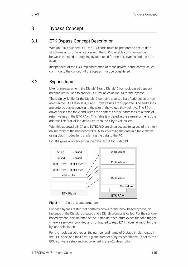
ETAS Bypass Concept
8 Bypass Concept
8.1 ETK Bypass Concept DescriptionWith an ETK equipped ECU, the ECU code must be prepared to set up data structures and communication with the ETK to enable communication between the rapid prototyping system used for the ETK bypass and the ECU itself.
Independent of the ECU implementation of these drivers, some safety issues common to the concept of the bypass must be considered.
8.2 Bypass InputLike for measurement, the Distab13 (and Distab12 for hook-based bypass) mechanism is used to provide ECU variables as inputs for the bypass.
The DISplay TABle for the Distab13 contains a sorted list of addresses of vari-ables in the ETK Flash. 8, 4, 2 and 1 byte values are supported. The addresses are ordered corresponding to the size of the values they point to. The ECU driver parses the table and writes the contents of the addresses to a table of return values in the ETK RAM. This table is ordered in the same manner as the address list: first, all 8 byte values, then the 4 byte values, etc.
With this approach, INCA and INTECRIO are given access to values of the inter-nal memory of the microcontroller. Also, collecting the data in a table allows using block modes for transferring the data to the PC.
Fig. 8-1 gives an overview on the data layout for Distab13.
Fig. 8-1 Distab13 data structure
For each bypass raster that contains hooks for the hook-based bypass, an instance of the Distab is created and a Distab process is called. For the service-based bypass, one instance of the Distab data structure exists for each trigger where a service is provided and configured to read ECU values as input for the bypass calculation.
For the hook-based bypass, the number and name of Distabs implemented in the ECU code, and their size, e.g. the number of bytes per channel, is set by the ECU software setup and documented in the A2L description.
ETK Flash
active unused
unusedunused
# of 8 bytes
# of 1 bytes# of 2 bytes
# of 4 bytes
address list
ETK RAM
64bit values
32bit values
16bit values
8bit values
INTECRIO V4.7 - User’s Guide 145
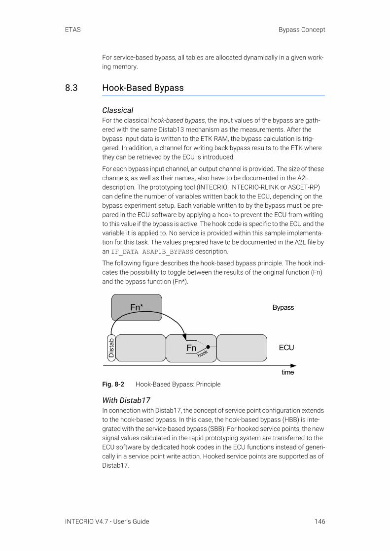
ETAS Bypass Concept
For service-based bypass, all tables are allocated dynamically in a given work-ing memory.
8.3 Hook-Based Bypass
ClassicalFor the classical hook-based bypass, the input values of the bypass are gath-ered with the same Distab13 mechanism as the measurements. After the bypass input data is written to the ETK RAM, the bypass calculation is trig-gered. In addition, a channel for writing back bypass results to the ETK where they can be retrieved by the ECU is introduced.
For each bypass input channel, an output channel is provided. The size of these channels, as well as their names, also have to be documented in the A2L description. The prototyping tool (INTECRIO, INTECRIO-RLINK or ASCET-RP) can define the number of variables written back to the ECU, depending on the bypass experiment setup. Each variable written to by the bypass must be pre-pared in the ECU software by applying a hook to prevent the ECU from writing to this value if the bypass is active. The hook code is specific to the ECU and the variable it is applied to. No service is provided within this sample implementa-tion for this task. The values prepared have to be documented in the A2L file by an IF_DATA ASAP1B_BYPASS description.
The following figure describes the hook-based bypass principle. The hook indi-cates the possibility to toggle between the results of the original function (Fn) and the bypass function (Fn*).
Fig. 8-2 Hook-Based Bypass: Principle
With Distab17In connection with Distab17, the concept of service point configuration extends to the hook-based bypass. In this case, the hook-based bypass (HBB) is inte-grated with the service-based bypass (SBB): For hooked service points, the new signal values calculated in the rapid prototyping system are transferred to the ECU software by dedicated hook codes in the ECU functions instead of generi-cally in a service point write action. Hooked service points are supported as of Distab17.
Dis
tab
Fn*
aFnhook
time
ECU
Bypass
INTECRIO V4.7 - User’s Guide 146

ETAS Bypass Concept
• In the following illustration, Fn denotes the original function that runs on the ECU.
Fig. 8-3 Bypass with hooked service points
• Prior to the execution of the original function that runs on the ECU, hooked service points can be used to receive data from the ECU to the rapid prototyping system via a read or receive pre-action. The associated hook codes are usually implemented at the end of the original function. The hooks receive their source (i.e. SOURCE_ID) and offset (i.e. BUFFER_OFFSET) information from the associated hook labels.
• During the execution of the original function in the ECU, the rapid proto-typing system writes data to a double-buffered send data table that can be accessed by these hooks in the original function. The two buffers are used alternately. Either the resulting bypass value or the value calculated internally by the original function is used.
8.4 Service-Based Bypass
For the service-based bypass, both the input values and the output values of the bypass function are transmitted with the same Distab13 mechanism. After the bypass input data is written to the ETK RAM, the bypass calculation is trig-gered. In addition, a channel for writing back bypass results to the ETK where they can be retrieved by the ECU is introduced. Here, each bypassed ECU pro-cess uses and calls its own Distab.
This service also contains an inverted Distab mechanism to write back bypass outputs to the ECU. The ECU does not need to apply hooks to the variables written to, since the service simply overwrites the values with the bypass out-puts. INTECRIO sets up a Distab-like sorted address table with the addresses of the ECU variables to be written to, and writes the corresponding values in a
NOTEService-based bypass on an ETK with 8 Mbit/s is not supported.
Rapid-Prototyping System
ECU
Hook labels
SOURCE_IDBUFFER-OFFSET
Send data table
Buffer 1Buffer 2
Fnbypass value
internally calculatedvalue
hookedservicepoint
rpre action
INTECRIO V4.7 - User’s Guide 147
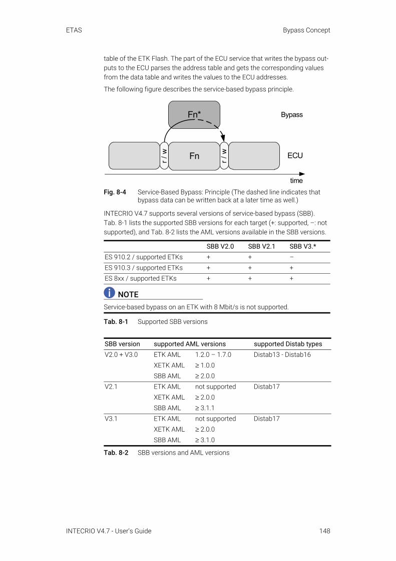
ETAS Bypass Concept
table of the ETK Flash. The part of the ECU service that writes the bypass out-puts to the ECU parses the address table and gets the corresponding values from the data table and writes the values to the ECU addresses.
The following figure describes the service-based bypass principle.
Fig. 8-4 Service-Based Bypass: Principle (The dashed line indicates that bypass data can be written back at a later time as well.)
INTECRIO V4.7 supports several versions of service-based bypass (SBB). Tab. 8-1 lists the supported SBB versions for each target (+: supported, –: not supported), and Tab. 8-2 lists the AML versions available in the SBB versions.
Tab. 8-1 Supported SBB versions
Tab. 8-2 SBB versions and AML versions
SBB V2.0 SBB V2.1 SBB V3.*ES 910.2 / supported ETKs + + –ES 910.3 / supported ETKs + + +ES 8xx / supported ETKs + + +
NOTEService-based bypass on an ETK with 8 Mbit/s is not supported.
SBB version supported AML versions supported Distab typesV2.0 + V3.0 ETK AML 1.2.0 – 1.7.0 Distab13 - Distab16
XETK AML ≥ 1.0.0SBB AML ≥ 2.0.0
V2.1 ETK AML not supported Distab17XETK AML ≥ 2.0.0SBB AML ≥ 3.1.1
V3.1 ETK AML not supported Distab17XETK AML ≥ 2.0.0SBB AML ≥ 3.1.0
r / w
Fn*
Fn r / w
time
ECU
Bypass
INTECRIO V4.7 - User’s Guide 148
ETAS Bypass Concept
8.5 Safety ConsiderationsWith calculating a bypass function on a rapid prototyping system and feeding data back into the ECU, the same care needs to be taken for development and use of bypass software as for ECU software. The bypass output may directly or indirectly influence the output channels of the ECU. The same applies, of course, if the rapid prototyping system uses own output channels.
Thus, it is highly recommended that the bypass functions include range checks and validations algorithms for the bypass outputs.
8.5.1 Bypass Input DataTo perform proper calculations, the bypass obviously needs consistent and valid input data. The ECU software must ensure this and prevent activation of the bypass if the ECU software detects incorrect or invalid inputs. This also includes ECU states like initialization and afterrun, or error modes the ECU might run in. In other words, activation of and data transfer to the bypass must be covered by the safety mechanisms of the ECU.
8.5.2 Bypass CalculationThe ECU software must be aware whether the bypass is active and must pro-vide measures to react on bypass failures, for example missing calculations or unexpected shut off of the bypass system.
Failsafe measures might be using the alternative output values of the bypassed ECU functions, using constant fallback values, or even resetting the ECU, depending on the bypassed ECU function. This is entirely under responsibility of the ECU provider who integrates the bypass drivers.
Some implementations of the ECU bypass drivers, as for the service-based bypass, allow the deactivation of the bypassed ECU function by the bypass user. In this case, the results of the bypassed ECU function obviously cannot be used as fallback. This must be considered when setting up a safety strategy.
8.5.3 Bypass Output DataThe ECU provider must guarantee that any value sent back by the bypass sys-tem leads to a predictable behavior of the ECU – the bypass output values must undergo the same range check and validation as the values calculated within the bypass.
As said before, the implementation of the ECU drivers must, in any case, ensure that bypass failures can be detected by the ECU and valid and safe fallback values are available at any time.
8.5.4 Message CopiesIf the ECU software contains message copies, the bypass must be aware of them.
The usual implementations of the hook-based bypass are an exception to that rule. Here, the hooks (and thus the messages written to) are known before compilation, so that the hook code can take care of and use message copies if needed—individual code and addresses are used at each hook.
INTECRIO V4.7 - User’s Guide 149

ETAS Bypass Concept
With the service-based bypass, users cannot choose variables and decide which message to write to before they set up the bypass experiment in INTEC-RIO. Thus, the services in the ECU are generic code and do not know about specific message copies.
This requires two steps:
A The ECU software provider must provide this message copy information in the A2L file (usually in encrypted and password-protected form).
B If the message copy information is encrypted, the user of the bypass system receives a password from the ECU software provider. He must enter this password to decrypt the information and use it for system configuration.
If one of these two steps is missing (usually a wrong password is entered), the bypass system has no knowledge of message copies and reads from / writes to the original variable address, as it is declared in the MEASUREMENT declara-tion of the A2L file. For receive variables, this yields old data values. For send variables, the data value written by the bypass model may be overwritten by other parts of the ECU software. Both cases may cause bypass malfunction!
Another principal problem can arise with ECU software that contains message copies. The original code to create the message copies for an ECU task was based on the given message usage and generated appropriate code. By writing variable values into the ECU via bypass methods, the data flow changes, and a new or different message copy may become necessary. This can result in wrong variable values in the ECU software even at locations which are not directly related to the bypassed functions. Whether writing to a certain variable at a certain location (e.g. service point) may be dangerous or not, can be answered only by the ECU software supplier. This information cannot be declared in the A2L file.
8.6 Service-Based Bypass SpecificsUnlike the hook-based bypass where either the ECU or the bypass writes to the bypassed variable, the service-based bypass has an inherent possibility of data inconsistency, since both the ECU and the bypass write to the same value con-secutively. Due to ECU real-time constraints, interrupts cannot be disabled to protect the sequence of writing the results of the ECU function and then writing the variable values of the bypass.
INTECRIO V4.7 - User’s Guide 150
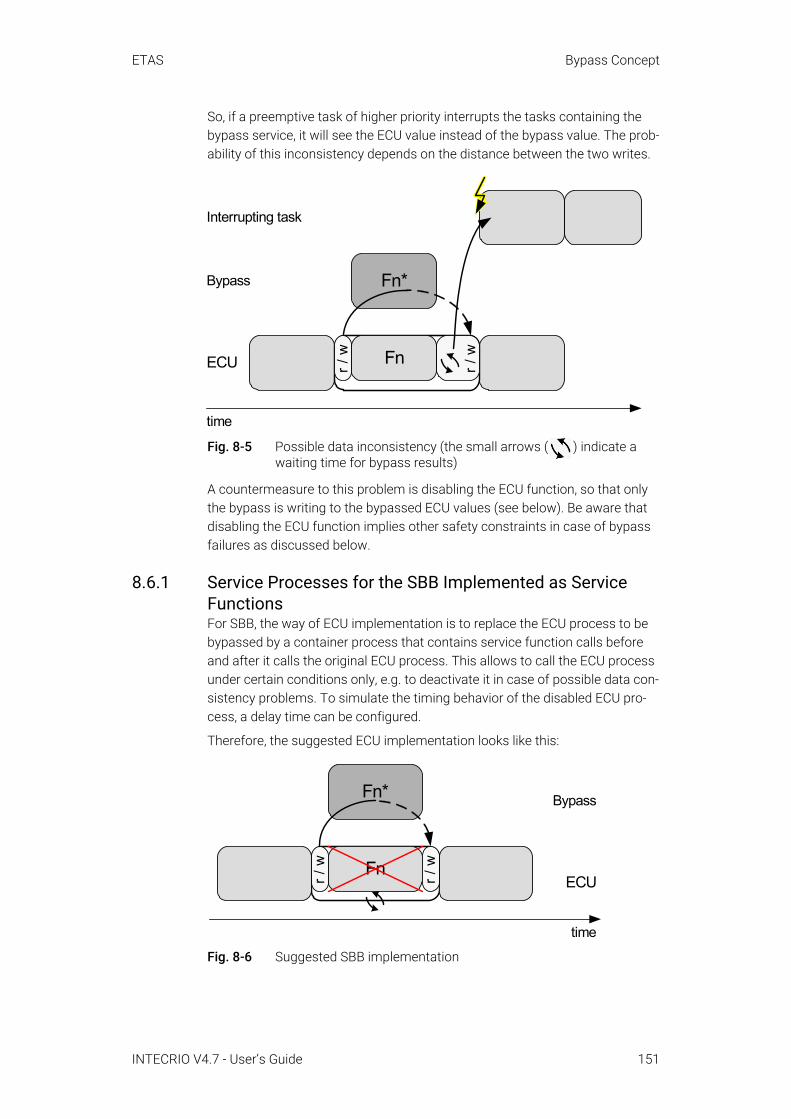
ETAS Bypass Concept
So, if a preemptive task of higher priority interrupts the tasks containing the bypass service, it will see the ECU value instead of the bypass value. The prob-ability of this inconsistency depends on the distance between the two writes.
Fig. 8-5 Possible data inconsistency (the small arrows ( ) indicate a waiting time for bypass results)
A countermeasure to this problem is disabling the ECU function, so that only the bypass is writing to the bypassed ECU values (see below). Be aware that disabling the ECU function implies other safety constraints in case of bypass failures as discussed below.
8.6.1 Service Processes for the SBB Implemented as Service FunctionsFor SBB, the way of ECU implementation is to replace the ECU process to be bypassed by a container process that contains service function calls before and after it calls the original ECU process. This allows to call the ECU process under certain conditions only, e.g. to deactivate it in case of possible data con-sistency problems. To simulate the timing behavior of the disabled ECU pro-cess, a delay time can be configured.
Therefore, the suggested ECU implementation looks like this:
Fig. 8-6 Suggested SBB implementation
Fn*
time
ECU
Bypass
Interrupting task
r / w Fn r / w
r / w
Fn*
Fn r / w
time
ECU
Bypass
INTECRIO V4.7 - User’s Guide 151

ETAS Bypass Concept
For setting up the bypass experiment in INTECRIO and implementing the ser-vice point in the ECU software as container process, a service point is defined as
A receiving data from the ECU (pre read action),
B waiting for data to be sent (a time-out is defined),
C sending data to the ECU (pre write action),
D conditionally executing the original ECU process,
E receiving data from the ECU (post read action),
F waiting for data to be sent (a time-out is defined),
G sending data to the ECU (post write action).
Each pre and post action can be freely configured or activated / deactivated.
8.6.2 Controlling the ECU Behavior from INTECRIOUpon setting up the INTECRIO experiment, an initial setting of the control vari-ables can be done in INTECRIO. These values are written to the ETK on experi-ment initialization.
The ECU function can be controlled by the INTECRIO user in several ways (if the ECU drivers also provide this functionality):
• The ECU function can be deactivated in the service point editor of INTEC-RIO ( column, see Fig. 8-7)
• The detection of a bypass error can be defined• The bypass error behavior of the ECU code can be influenced
Fig. 8-7 Controlling ECU function execution from INTECRIO(The columns "Cluster Group" and "Cluster" are only available for SBB V3.*.The "Raster Usage" display is only available for SBB V2.*.)
8.6.3 OS Configuration for Service-Based Bypass V3This section explains some ways how to configure the operating system for a system project with service-based bypass V3.
8.6.3.1 RestrictionsThe following restrictions are valid for OS configuration of a system project with service-based bypass V3:
INTECRIO V4.7 - User’s Guide 152
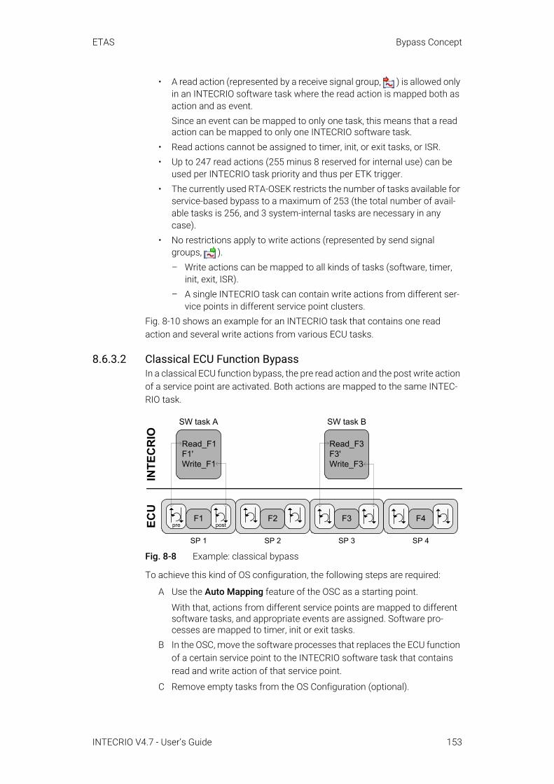
ETAS Bypass Concept
• A read action (represented by a receive signal group, ) is allowed only in an INTECRIO software task where the read action is mapped both as action and as event.Since an event can be mapped to only one task, this means that a read action can be mapped to only one INTECRIO software task.
• Read actions cannot be assigned to timer, init, or exit tasks, or ISR.• Up to 247 read actions (255 minus 8 reserved for internal use) can be
used per INTECRIO task priority and thus per ETK trigger.• The currently used RTA-OSEK restricts the number of tasks available for
service-based bypass to a maximum of 253 (the total number of avail-able tasks is 256, and 3 system-internal tasks are necessary in any case).
• No restrictions apply to write actions (represented by send signal groups, ). – Write actions can be mapped to all kinds of tasks (software, timer,
init, exit, ISR).– A single INTECRIO task can contain write actions from different ser-
vice points in different service point clusters.Fig. 8-10 shows an example for an INTECRIO task that contains one read action and several write actions from various ECU tasks.
8.6.3.2 Classical ECU Function BypassIn a classical ECU function bypass, the pre read action and the post write action of a service point are activated. Both actions are mapped to the same INTEC-RIO task.
Fig. 8-8 Example: classical bypass
To achieve this kind of OS configuration, the following steps are required:
A Use the Auto Mapping feature of the OSC as a starting point.
With that, actions from different service points are mapped to different software tasks, and appropriate events are assigned. Software pro-cesses are mapped to timer, init or exit tasks.
B In the OSC, move the software processes that replaces the ECU function of a certain service point to the INTECRIO software task that contains read and write action of that service point.
C Remove empty tasks from the OS Configuration (optional).
Read_F1F1'Write_F1
SW task A
ECU
preF1
post
SP 1
INTE
CR
IO
SP 3
SW task B
Read_F3F3'Write_F3
F3F2
SP 2
F4
SP 4
INTECRIO V4.7 - User’s Guide 153

ETAS Bypass Concept
Fig. 8-9 OS configuration for a classical ECU function bypass
8.6.3.3 Bypass of an Entire ECU FunctionalityOne INTECRIO task may contain pre and post write actions from different ser-vice points and ECU tasks. This can be used to bypass the entire ECU function-ality (consisting of several processes in different ECU tasks), which minimizes the number of interrupts and thus latency. Read signals are not updated while the task runs on the rapid prototyping target. Partial results are sent to the ECU as fast as possible to ensure the currency of the values of other functions.
In the example shown in Fig. 8-10, service points SP 1 and SP 2 belong to a high-priority ECU task A. Service point SP 3 belongs to a medium-priority ECU task B. Service point SP n belongs to a low-priority ECU task C. The read action of SP 1 and the write actions of all service points are assigned to the same INTECRIO software task.
Fig. 8-10 Example: Bypass of an entire ECU functionality
To achieve this kind of OS configuration, the following steps are required:
Read_F1F1'Write_F1F2'Write_F2F3'Write_F3…Fn’Write_FnIN
TEC
RIO
ECU ECU task A
ECU task B
ECU task C
F1 F2
F3
Fn
SP 1 SP 2
SP 3
SP n
SW task
INTECRIO V4.7 - User’s Guide 154

ETAS Bypass Concept
A Use the Auto Mapping feature of the OSC as a starting point.
With that, actions from different service points are mapped to different software tasks, and appropriate events are assigned. Software pro-cesses are mapped to timer, init or exit tasks.
B In the OSC, move the write actions (i.e. send signal groups) from the fast-est timer task, where they were mapped automatically, to the INTECRIO software task that contains the read action of SP 1.
You may use the "Hardware" tab of the OSC to search for a particular signal group, and the Search context menu of the group to locate it in the OS configuration tree view.
C Move the software processes to the same INTECRIO software task as the write actions.
You may use the "Software" tab of the OSC to search for a particular pro-cess, and the Search context menu of the process to locate it in the OS configuration tree view.
D Remove empty tasks from the OS Configuration (optional).
Fig. 8-11 OS configuration for the bypass of an entire ECU functionality
8.6.3.4 Read and Write Actions of the Same Service Point in Different RastersThe read action and the write action of the same service point can be config-ured independently, they can be assigned to different tasks with different events or periodicities.
INTECRIO V4.7 - User’s Guide 155
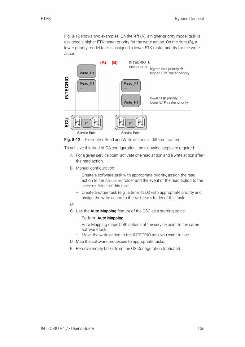
ETAS Bypass Concept
Fig. 8-12 shows two examples. On the left (A), a higher-priority model task is assigned a higher ETK raster priority for the write action. On the right (B), a lower priority model task is assigned a lower ETK raster priority for the write action.
Fig. 8-12 Examples: Read and Write actions in different rasters
To achieve this kind of OS configuration, the following steps are required:
A For a given service point, activate one read action and a write action after the read action.
B Manual configuration:
– Create a software task with appropriate priority, assign the read action to the Actions folder and the event of the read action to the Events folder of this task.
– Create another task (e.g., a timer task) with appropriate priority and assign the write action to the Actions folder of this task.
OrC Use the Auto Mapping feature of the OSC as a starting point:
– Perform Auto Mapping.Auto Mapping maps both actions of the service point to the same software task.
– Move the write action to the INTECRIO task you want to use.D Map the software processes to appropriate tasks.
E Remove empty tasks from the OS Configuration (optional).
INTE
CR
IO
Read_F1...
...Write_F1
...Write_F1
Read_F1...
ECU
F1
Service Point
F1
Service Point
INTECRIOtask priority higher task priority
higher ETK raster priority
lower task priority lower ETK raster priority
(A) (B)
INTECRIO V4.7 - User’s Guide 156

ETAS Bypass Concept
Fig. 8-13 OS configuration (incomplete) for a bypass with read and write actions of a service point in different tasks
8.6.3.5 ECU-Synchronous Write-BackThe idea of ECU-synchronous write-back is to calculate results at the earliest possible stage on the rapid prototyping system (E-target) so it can be retrieved by the ECU at the right point-in-time.
Fig. 8-14 illustrates how service points can be used for ECU-synchronous write-back. Following the pre-action Read_F1 of service point SP 1, the result, F3', is available in the rapid prototyping system, but not in the ECU. At the right point in time, service point SP 3 fetches F3' and writes the result to the ECU as F3. Note that the (Read_F3) action is a "dummy" action that merely serves to release the ETK channel, and that no signal has to be selected for that dummy signal group.
Fig. 8-14 Example: ECU-synchronous write-back
To achieve this kind of OS configuration, the following steps are required:
A Use the Auto Mapping feature of the OSC as a starting point.
With that, actions from different service points are mapped to different software tasks, and appropriate events are assigned. Software pro-cesses are mapped to timer, init or exit tasks.
Read_F1...F3'
SW task A
ECU
preF1
post
SP 1
INTE
CRI
O
SP 3
SW task B
(Read_F3)
Write_F3
F3
INTECRIO V4.7 - User’s Guide 157
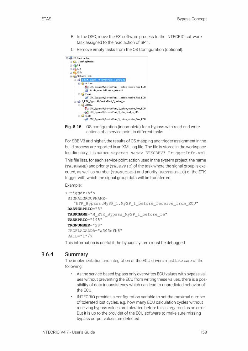
ETAS Bypass Concept
B In the OSC, move the F3’ software process to the INTECRIO software task assigned to the read action of SP 1.
C Remove empty tasks from the OS Configuration (optional).
Fig. 8-15 OS configuration (incomplete) for a bypass with read and write actions of a service point in different tasks
For SBB V3 and higher, the results of OS mapping and trigger assignment in the build process are reported in an XML log file. The file is stored in the workspace log directory, it is named <system name>_ETKSBBV3_TriggerInfo.xml.
This file lists, for each service-point action used in the system project, the name (TASKNAME) and priority (TASKPRIO) of the task where the signal group is exe-cuted, as well as number (TRGNUMBER) and priority (RASTERPRIO) of the ETK trigger with which the signal group data will be transferred.
Example:
<TriggerInfo SIGNALGROUPNAME=
"ETK_Bypass.MySP_1.MySP_1_before_receive_from_ECU"RASTERPRIO="8" TASKNAME="M_ETK_Bypass_MySP_1_before_re" TASKPRIO="195" TRGNUMBER="28" TRGFLAGADDR="a303efb8" RAID="1"/>
This information is useful if the bypass system must be debugged.
8.6.4 SummaryThe implementation and integration of the ECU drivers must take care of the following:
• As the service-based bypass only overwrites ECU values with bypass val-ues without preventing the ECU from writing these values, there is a pos-sibility of data inconsistency which can lead to unpredicted behavior of the ECU.
• INTECRIO provides a configuration variable to set the maximal number of tolerated lost cycles, e.g. how many ECU calculation cycles without receiving bypass values are tolerated before this is regarded as an error. But it is up to the provider of the ECU software to make sure missing bypass output values are detected.
INTECRIO V4.7 - User’s Guide 158

ETAS Bypass Concept
• INTECRIO provides a configuration variable to set a specific error behav-ior (if also supported by the ECU implementation). But it is up to the pro-vider of the ECU software to make sure bypass failures or bypass deactivation can be detected by the ECU software! The configuration setting in the INTECRIO GUI can then be used to choose between differ-ent provided error behaviors in the ECU.
• INTECRIO allows disabling the bypassed ECU process. In this case, no ECU values can be used as fallback values for bypass failures! It is up to the provider of the ECU software to make sure sensible data is written to the variables if both the ECU process and the bypass is disabled.
INTECRIO V4.7 - User’s Guide 159

ETAS Glossary
9 GlossaryThis glossary contains explanations of the technical terms and abbreviations used in the INTECRIO documentation. While many terms are also used in a more general sense, this glossary specifically addresses the meaning of those terms as they are applied to INTECRIO. The terms are listed in alphabetical order.
9.1 AbbreviationsABS
Antilock Braking SystemAPI
Programming interface for the application developer (Application Programming Interface).
ASAM-MCDWorking Group for Standardizing Automation and Measuring Systems, including the Working Groups Measuring, Calibrating, and Diagnostics (German: Arbeitskreis zur Standardisierung von Automations- und Messsystemen, mit den Arbeitsgruppen Messen, Calibrieren und Diagnose)
ASAM-MCD-2MCA file format used to describe the calibration variables and measured signals contained in the control unit software, and additional specific information designed to parameterize the experiment interface. ASAM-MCD-2MC is used to import the information required for this into an experiment (A2L file).INTECRIO V4.7 supports the ETK AML versions 1.1 (only hook-based bypass) or 1.2 – 1.7 (hook-based and service-based bypass), XETK AML versions up to 2.5, ASAP1B_Bypass AML V1.0 and higher, and SBB AML versions 2.0, 3.0 and 3.1. For further information, refer to http://www.asam.net.
ASCETETAS product family for the development of electronic control unit soft-ware. ASCET models can be imported in INTECRIO.
ASCET-MDASCET Modeling & Design – the behavioral modeling tool of the ASCET product family.
ASCET-RPASCET Rapid Prototyping – the rapid prototyping tool of the ASCET product family.
AUTOSARAutomotive Open System Architecture; see http://www.autosar.org/
BMTBehavioral Modeling Tool. The BMT can be used to edit, simulate and animate the behavior of models and generate the function code.
BR_XETKEmulator test probe (ETK) with Automotive Ethernet interface. Requires an ES800 hardware system with ES882/ES886.
INTECRIO V4.7 - User’s Guide 160
ETAS Glossary
BSWBasic software; provides communications, I/O, and other functionality that all software components are likely to require.
CANController Area Network; a robust vehicle bus standard designed to allow microcontrollers and devices to communicate with each others' applications without a host computer.
CANdbCAN database; CAN description file created with the CANdb data man-agement program made by the company Vector Informatik. INTECRIO V4.7 supports the CANdb versions V2.3 and higher.
CPUCentral Processing Unit. In the context of INTECRIO, this refers to a sin-gle microcontroller.
DistabData exchange method, used in ETK bypass experiments for data exchange between experimental target and ECU. INTECRIO V4.7 supports hook-based bypass with Distab 12 and higher (XETK AML: Distab 13), as well as service-based bypass with Distab 13.In combination with ES830 or ES910.3, INTECRIO V4.7 supports also bypass with Distab 17.
ECUElectronic Control Unit; a small embedded computer system that con-sists of a CPU and the associated periphery, where everything is usually located in the same housing.
ESPElectronic Stability Program
ETKemulator test probe (German: Emulator-Tastkopf)
FETKemulator test probe (ETK) for the ETAS ES89x ECU and Bus Interface Modules
FIBEXField Bus Exchange – an exchange format based on an XML schema which is used for descriptions of the complete in-vehicle communication network. FIBEX is defined for various network types (CAN, LIN, MOST, FlexRay) and contains information about bus architecture, signals, prop-erties of network nodes, etc. The FIBEX file format is standardized by ASAM (Association for Stan-dardization of Automation and Measuring Systems).INTECRIO V4.7 supports the FIBEX baseline versions FIBEX V2.0.x and V3.1.0; the latter with some restrictions (see the online help for details).For further information, refer to http://www.asam.net.
FIFOFirst in, first out
HBBhook-based bypass
INTECRIO V4.7 - User’s Guide 161
ETAS Glossary
HCHardware Configurator
IERINTECRIO Embedded Coder Real-Time Target (Embedded Coder real-time target for importing Simulink models in INTECRIO)
INCAETAS measuring, calibration and diagnostics system (Integrated Calibration and Acquisition Systems)For cooperation with INTECRIO V4.7.3, you need INCA V7.2.17 or higher.
INCA-EIPINCA add-on; allows access to the rapid prototyping (ES910, ES830) and virtual prototyping (VP-PC) targets for INCA.For cooperation with INTECRIO V4.7.3, you need INCA-EIP V7.2.17 or higher.
INTECRIO-RPINTECRIO Rapid Prototyping package – provides connectivity to the rapid prototyping targets.
INTECRIO-VPINTECRIO Virtual Prototyping package – provides connectivity to the vir-tual prototyping targets.
IRTINTECRIO Real-Time Target (Simulink Coder real-time target for import-ing Simulink models in INTECRIO)
LDFLIN description file – a configuration file for a LIN controller. INTECRIO V4.7.3 supports the LDF versions 1.3, 2.0, 2.1, and 2.2.
LINLocal Interconnect Network; a serial network protocol used for commu-nication between components in vehicles. LIN is used where the bandwidth and versatility of CAN are not needed. Typical application examples are the networking within the door or the seat of a motor vehicle.
LSB and lsbLeast Significant Byte (capital letters) or bit (small letters)
MDA
Measure Data Analyzer program; an offline instrument by ETAS for dis-playing and analyzing saved measurement data.
MSB and msbMost Significant Byte (capital letters) or bit (small letters)
OILOSEK Implementation Language – as describing language for electronic control unit networks, it is an indirect part of the OSEK operating system. OIL is used to describe static information of the electronic control unit network, such as communication connections and electronic control unit properties.
INTECRIO V4.7 - User’s Guide 162
ETAS Glossary
OSOperating System
OSC OS configurator (Operating System Configurator)
OSEKWorking group for Open Systems for Electronics in Motor Vehicles (Ger-man: Offene Systeme für die Elektronik im Kraftfahrzeug)
PDUProtocol data unit; a data unit that contains payload and control informa-tion which is passed between the layers in a protocol stack.In INTECRIO V4.7, a FlexRay PDU corresponds to a signal group.
RERunnable entity; a a piece of code in an SWC that is triggered by the RTE at runtime. It corresponds largely to the processes known in INTECRIO.
RTA-OSEKETAS real-time operating system; implements the AUTOSAR-OS V1.0 (SC-1) and OSEK/VDX OS V2.2.3 standards and is fully MISRA compli-ant.
RTA-OSETAS real-time operating system; implements the AUTOSAR R3.0 OS and OSEK/VDX OS V2.2.3 standards and is fully MISRA compliant.
RTA-RTEAUTOSAR runtime environment by ETAS
RTEAUTOSAR runtime environment; provides the interface between soft-ware components, basic software, and operating systems.
RTIOReal-Time Input-Output
SBBservice-based bypass
SBCElectrohydraulic brake system (Sensotronic Brake Control)
SCOOPSource Code, Objects, and Physics
SCOOP-IXSCOOP Interface Exchange language. INTECRIO V4.7 supports SCOOP-IX versions V1.0, V1.1, V1.2, V1.4, and V1.5.
SPservice point; see also page 167
SWCAtomic AUTOSAR software component; the smallest non-dividable soft-ware unit in AUTOSAR.
UDPUser Datagram Protocol
INTECRIO V4.7 - User’s Guide 163

ETAS Glossary
UMLUnified Modeling Language
VFBVirtual function bus in AUTOSAR
XCPUniversal measurement and calibration protocol; the x generalizes the various transportation layers that can be used. The long name is ASAM MCD-1 XCP.INTECRIO V4.7 supports XCP version V1.0 and all subsequent versions which are compatible with V1.0. In addition, the XCPplus keyword from V1.1 and higher is supported.
XETKemulator test probe (ETK) with Ethernet interface
XMLExtensible Markup Language
9.2 TermsActuator
Executing hardware unit. It forms the physical interface between elec-tronic signal processing and mechanics.
Application modeAn application mode is part of the operating system; it describes differ-ent possible states of a system, such as the application mode EEPROM programming mode, starting or normal operation.
AUTOSAR software componentsee SWC
Basic softwaresee BSW
Bypass experimentIn a bypass experiment, parts of an electronic control unit program are executed on the experimental target (ES900, ES800). This requires a special hook in the code.INTECRIO V4.7 supports several types of bypass experiments: XCP bypass on CAN or UDP, as well as hook-based and service-based ETK/XETK/FETK bypass.
Connection, dynamicConnection between signal source and sink that can be changed at run-time without a new build process.
Connection, staticConnection between signal source and sink that cannot be changed at runtime.
Crossbar Manages and controls the connections between modules, functions and hardware in a non-AUTOSAR environment.
Embedded CoderTM
INTECRIO V4.7 - User’s Guide 164
ETAS Glossary
An add-on for the Simulink® CoderTM; extends the capabilities provided by the Simulink Coder to support specification, integration, deployment, and testing of production applications on embedded targets.
Environment systemEnvironment systems are used to model the plant model for virtual pro-totyping. They are built out of modules and functions, the same way as software systems.
EventAn event is an (external) trigger that initiates an action of the operating system, such as a task.
Event interfacesee Process
FlexRayFlexRay is a scalable and fault tolerant communication system for high-speed and deterministic data exchange. FlexRay’s time-division multi-plexing facilitates the design of modular or safety-related distributed systems. Its high bandwidth of 10 MBaud on two channels helps to cope with the high network load caused by the increasing amount of innova-tive electronic systems in modern vehicles. The communication system’s specifications are released by the FlexRay consortium which is widely supported by vehicle manufacturers and suppliers worldwide.
Fullpass experimentIn a fullpass experiment, the complete electronic control unit program is executed on the experimental target.
FunctionA grouping object for software systems that does not feature its own functionality. Modules or functions are assembled and connected in a function; they are thus clearly arranged and can be easily reused.
Graphical frameworkThe window that displays after the start of INTECRIO. The different INTECRIO components are integrated in the graphical framework.
Hardware systemA hardware system contains the complete description of a hardware topology, consisting of the descriptions of the associated ECUs (experi-mental targets) as well as the descriptions of the interfaces (bus sys-tems) between the devices.
ImplementationAn implementation describes the conversion of the physical task defini-tion (of the model) into executable fixed-point code. An implementation consists of a (linear) conversion formula and a limiting interval for the model values.
IntegrationThe convergence of model code, which may have been developed by dif-ferent partners or with different tools, to control algorithm, the configura-tion of this algorithm for the hardware on which it is supposed to run, and finally the creation of an executable file.
INTECRIO
INTECRIO V4.7 - User’s Guide 165
ETAS Glossary
INTECRIO is a tool that combines, i.e. integrates, the parts of the control algorithm created with different behavioral modeling tools that allows for creating and configuring a hardware system and the connection of this hardware system with the control algorithm.
MATLAB®
High-performance language for technical calculations; contains mathe-matical calculations, visualization and programming in one environ-ment.
MATLAB® CoderTM
Code generator for MATLAB code.Module
A module in INTECRIO contains the generic description of a functionality for an electronic control unit. For example, it corresponds to an ASCET project or a Simulink model.
OS configurator and OSCThe task of the operating system configuration is carried out within INTECRIO the OS configurator and the OSC editor. The OSC is part of the OS configurator, an easy to handle editor for the operating system con-figuration that provides the user with a quick overview of the system and allows for editing the configuration in an application-oriented display.
ProcessA process is a simultaneously executable functionality that is activated by the operating system. Processes are specified in modules and do not feature any arguments/inputs or result values/outputs.
Processorsee CPU
Project ConfiguratorThe project configurator is part of the integration platform of INTECRIO. It is used to specify software systems and system projects.
Project IntegratorThe project integrator combines all the components of the system (mod-ules and functions, hardware interfacing, OS configuration, etc.) into an executable file.
PrototypeCompletely executable file for an experimental target system. Such a prototype shows the software functions in practical use – entirely with different goal directions and in a different appropriation.
Rapid prototypingThe execution of a software on an experimental target, i.e. a computer with an interface to the vehicle.
RTA-TraceSoftware tracing tool that can monitor system behavior over a versatile interface to the ECU.
Runnable entitysee RE
Runtime environmentsee RTE
Sensor
INTECRIO V4.7 - User’s Guide 166
ETAS Glossary
Sensors convert a physical or chemical (usually nonelectrical) quantity into an electrical quantity.
Service pointA service point is an encapsulation of a process in the ECU software. It provides data transfer actions to and from the target system; these actions can be enabled and configured by the user.
Service point clusterA group of service points that are executed in the ECU with the same priority (service points located in the same ECU task).
Service point cluster groupA group of service point clusters. The group contains all service points of all tasks that can potentially be invoked at the same time in the ECU.
Simulink®
Tool for modeling, simulation and analysis of dynamic systems. The models can be imported in INTECRIO.
Simulink® CoderTM
Code generator for Simulink and Stateflow models. Requires the MATLAB® CoderTM.
Stateflow® Tool for modeling and simulation of complex event-controlled systems. It is seamlessly integrated in MATLAB and Simulink.
Software systemA software system contains the generic parts of the ECU description: modules, functions and connections.
System projectA system project combines a hardware system, a software system, an environment system (if applicable), the mapping of the signals and the configuration of the operating system in a common project and allows for the generation of executable code.
TaskA task is an ordered collection of processes that can be activated by the operating system. Attributes of a task are its application modes, activa-tion trigger, priority and modes of its scheduling. Upon activation, the processes of the task are executed in the specified order.
ValidationProcess for the evaluation of a system or a component with the purpose of determining whether the application purpose or the user expectations are met. Therefore, the validation is the check whether the specification meets the user requirements, whether the user acceptance is reached by a function after all.
VerificationProcess for evaluating a system or a component with the purpose of determining whether the results of a given development phase corre-spond to the specifications for this phase. Therefore, software verifica-tion is the check whether an implementation of the specification specified for the respective development step is sufficient.
Virtual prototypingFunction developers create virtual prototypes of electronic vehicle func-tions and test them on the PC.
INTECRIO V4.7 - User’s Guide 167

ETAS Glossary
WorkspaceThe workspace combines all the data generated while working with INTECRIO. From the WS browser, i.e. the tree view of the workspace, you can call up all the components of INTECRIO.
X-Pass experimentMixture of bypass and fullpass experiment. The experimental target (ES900, ES800) utilizes the ECU with bypass hooks as interface to the outside world.
INTECRIO V4.7 - User’s Guide 168

ETAS Contact Information
INTECRIO V4.7 - User’s Guide 169
10 Contact Information
ETAS HeadquartersETAS GmbH
ETAS Subsidiaries and Technical SupportFor details of your local sales office as well as your local technical support team and product hotlines, take a look at the ETAS website:
Borsigstraße 24 Phone: +49 711 3423-070469 Stuttgart Fax: +49 711 3423-2106Germany Internet: www.etas.com
ETAS subsidiaries Internet: www.etas.com/en/contact.phpETAS technical support Internet: www.etas.com/en/hotlines.php
ETAS Figures
Figures
Fig. 3-1 INTECRIO – Overview . . . . . . . . . . . . . . . . . . . . . . . . . . . . . . . . . . . . . . . . . . . . . . . . .12Fig. 3-2 Overview of the development of electronic systems . . . . . . . . . . . . . . . . . . . . . . .13
Fig. 3-3 Functions and electronic control units per vehicle (in The Need for Systems Engineering. An Automotive Project Perspective, Key Note at the 2nd European Systems Engineering Conference, Munich, H.-G. Frischkorn, H. Negele, J. Meisenzahl) . . . . . . . . . . . . . . . . . . . . . . . . . . . . . . . . . . . . . . . . . . . . . .14
Fig. 3-4 Responsibilities of car manufacturers and suppliers. The interfaces entered (dot-dash-lines) are examples. . . . . . . . . . . . . . . . . . . . . . . . . . . . . . . . . . . . . . . . . . .16
Fig. 3-5 Design of the electrohydraulic brake (in Konventionelle und elektronische Bremssysteme, Robert Bosch GmbH (ed.), Stuttgart, 2002) . . . . . . . . . . . . . . . .17
Fig. 3-6 Schematic representation of control/closed-loop control and tracing systems . . . . . . . . . . . . . . . . . . . . . . . . . . . . . . . . . . . . . . . . . . . . . . . . . . . . . . . . . . . . .18
Fig. 3-7 Architecture of an electronic control unit description . . . . . . . . . . . . . . . . . . . . . .19
Fig. 3-8 Electronic control unit description: Overview (INTECRIO view) . . . . . . . . . . . . . .19
Fig. 3-9 Functional software: Details . . . . . . . . . . . . . . . . . . . . . . . . . . . . . . . . . . . . . . . . . . . .20
Fig. 3-10 Module/SWC: Schematic design (external view) and connection . . . . . . . . . . .20
Fig. 3-11 Modules: schematic internal view . . . . . . . . . . . . . . . . . . . . . . . . . . . . . . . . . . . . . . .21
Fig. 3-12 Module: ASCET example . . . . . . . . . . . . . . . . . . . . . . . . . . . . . . . . . . . . . . . . . . . . . . .21
Fig. 3-13 Module: Simulink® example . . . . . . . . . . . . . . . . . . . . . . . . . . . . . . . . . . . . . . . . . . . .22
Fig. 3-14 Internal view and component view of a module (dashed: descriptions; solid: implementations) . . . . . . . . . . . . . . . . . . . . . . . . . . . . . . . . . . . . . . . . . . . . . . . .23
Fig. 3-15 System project (electronic control unit description) and INTECRIO components . . . . . . . . . . . . . . . . . . . . . . . . . . . . . . . . . . . . . . . . . . . . . . . . . . . . . . . . .24
Fig. 3-16 Top: During simulation in scaled time, slow motion timing or fast forward timing can be achieved (within the limits of model complexity and computational power).Bottom: In a simulation with adaptive time, complex models can be executed at the fastest possible speed (i.e., the least possible computation time). . . . . . . . . . . . . . . . . . . . . . . . . . . . . . . . . . . . . . . . . . . . . . . . . . . . . . . . . . . . . . . . .26
Fig. 3-17 V cycle and INTECRIO . . . . . . . . . . . . . . . . . . . . . . . . . . . . . . . . . . . . . . . . . . . . . . . . .27
Fig. 3-18 INTECRIO – Scheme of the interface . . . . . . . . . . . . . . . . . . . . . . . . . . . . . . . . . . . .28
Fig. 3-19 Folder structure: workspace . . . . . . . . . . . . . . . . . . . . . . . . . . . . . . . . . . . . . . . . . . . .29
Fig. 3-20 Folder structure: hardware systems . . . . . . . . . . . . . . . . . . . . . . . . . . . . . . . . . . . . .29
Fig. 3-21 Folder structure: software systems and environment systems . . . . . . . . . . . . .30
Fig. 3-22 Folder structure: system project (objects marked with * are referenced) . . . . .31
Fig. 3-23 The software system . . . . . . . . . . . . . . . . . . . . . . . . . . . . . . . . . . . . . . . . . . . . . . . . . .32
Fig. 3-24 Connections: A source, one or several sinks, same timing . . . . . . . . . . . . . . . . .33
Fig. 3-25 Connection: One source, several sinks, different timing . . . . . . . . . . . . . . . . . . . .33
Fig. 3-26 Connection: several sources, one sink . . . . . . . . . . . . . . . . . . . . . . . . . . . . . . . . . . .33
Fig. 3-27 Example for a function . . . . . . . . . . . . . . . . . . . . . . . . . . . . . . . . . . . . . . . . . . . . . . . .34
INTECRIO V4.7 - User’s Guide 170

ETAS Figures
Fig. 3-28 Example for a software system . . . . . . . . . . . . . . . . . . . . . . . . . . . . . . . . . . . . . . . . .35
Fig. 3-29 The hardware system. . . . . . . . . . . . . . . . . . . . . . . . . . . . . . . . . . . . . . . . . . . . . . . . . .36
Fig. 3-30 System project . . . . . . . . . . . . . . . . . . . . . . . . . . . . . . . . . . . . . . . . . . . . . . . . . . . . . . .37
Fig. 3-31 Assigning processes to tasks . . . . . . . . . . . . . . . . . . . . . . . . . . . . . . . . . . . . . . . . . .38
Fig. 3-32 Crossbar – Overview . . . . . . . . . . . . . . . . . . . . . . . . . . . . . . . . . . . . . . . . . . . . . . . . . .39
Fig. 3-33 Prototype for rapid or virtual prototyping experiment . . . . . . . . . . . . . . . . . . . . . .40
Fig. 3-34 Different models that can be connected with the hardware as an option . . . . .41
Fig. 4-1 AUTOSAR software component (SWC) communications are represented by a virtual function bus (VFB) implemented through the use of the runtime environment (RTE) and basic software (BSW). . . . . . . . . . . . . . . . . . . . . . . . . . . .43
Fig. 4-2 Integration (left) of software modules for virtual prototyping (middle) or rapid prototyping (right) with the AUTOSAR RTE.AUTOSAR SWC can be combined with legacy functions (B) or tested as a pure AUTOSAR system (C). By using plant models, Model-in-the-Loop experiments are realized on the PC. . . . . . . . . . . . . . . . . . . . . . . . . . . . . . . . . . . . . . . . . . . . . . . . . . . . . . . . . . . . . . .45
Fig. 5-1 INTECRIO – components (black: INTECRIO, dark gray: INTECRIO-related ETAS tools, light gray: ETAS tools that can be used to experiment with INTECRIO) . . . . . .51
Fig. 5-2 INTECRIO-IP: MATLAB® and Simulink® connectivity . . . . . . . . . . . . . . . . . . . . . .52
Fig. 5-3 ASCET connectivity . . . . . . . . . . . . . . . . . . . . . . . . . . . . . . . . . . . . . . . . . . . . . . . . . . .55
Fig. 5-4 INTECRIO workspace browser with discontinued hardware . . . . . . . . . . . . . . . .58
Fig. 5-5 Ethernet and XCP on UDP structure in the WS browser . . . . . . . . . . . . . . . . . . . .60
Fig. 5-6 INTECRIO-RP: ES900 connectivity . . . . . . . . . . . . . . . . . . . . . . . . . . . . . . . . . . . . . .61
Fig. 5-7 Hardware Configurator – diagram . . . . . . . . . . . . . . . . . . . . . . . . . . . . . . . . . . . . . .62
Fig. 5-8 Display of the interfaces in the WS browser . . . . . . . . . . . . . . . . . . . . . . . . . . . . . .65
Fig. 5-9 Display of the CAN IO interface in the WS browser . . . . . . . . . . . . . . . . . . . . . . . .67
Fig. 5-10 Display of the FlexRay interface in the WS browser . . . . . . . . . . . . . . . . . . . . . . .71
Fig. 5-11 INTECRIO-RP: ES800 connectivity . . . . . . . . . . . . . . . . . . . . . . . . . . . . . . . . . . . . . .73
Fig. 5-12 Display of the ES800 interfaces in the WS browser . . . . . . . . . . . . . . . . . . . . . . . .78
Fig. 5-13 Display of the CAN IO interface (ES800) in the WS browser . . . . . . . . . . . . . . . .79
Fig. 5-14 INTECRIO-VP: VP-PC connectivity . . . . . . . . . . . . . . . . . . . . . . . . . . . . . . . . . . . . . .84
Fig. 5-15 The project configurator . . . . . . . . . . . . . . . . . . . . . . . . . . . . . . . . . . . . . . . . . . . . . . .85
Fig. 5-16 Standard layout of a module/SWC (a: Simulink module, b: ASCET module, c: AUTOSAR SWC, d: environment module) . . . . . . . . . . . . . . . . . . . . . . . . . . . . . . . . . . . . . . . . . . . . . . . . . . . . . . . . . . . . .86
Fig. 5-17 Standard layout (external view) of a function (a) and environment function (b) . . . . . . . . . . . . . . . . . . . . . . . . . . . . . . . . . . . . . . . . . . . . . . . . . . . . . . . . . .87
Fig. 5-18 Standard layout of a software system (a) and environment system (b) . . . . . .88
Fig. 5-19 System project in the graphical editor . . . . . . . . . . . . . . . . . . . . . . . . . . . . . . . . . . .89
Fig. 5-20 The OS configurator . . . . . . . . . . . . . . . . . . . . . . . . . . . . . . . . . . . . . . . . . . . . . . . . . . .90
Fig. 5-21 Task scheme . . . . . . . . . . . . . . . . . . . . . . . . . . . . . . . . . . . . . . . . . . . . . . . . . . . . . . . . .91
INTECRIO V4.7 - User’s Guide 171
ETAS Figures
Fig. 5-22 Task states and transitions . . . . . . . . . . . . . . . . . . . . . . . . . . . . . . . . . . . . . . . . . . . .92
Fig. 5-23 Cooperative scheduling . . . . . . . . . . . . . . . . . . . . . . . . . . . . . . . . . . . . . . . . . . . . . . . .93
Fig. 5-24 Preemptive scheduling . . . . . . . . . . . . . . . . . . . . . . . . . . . . . . . . . . . . . . . . . . . . . . . .93
Fig. 5-25 Data inconsistency . . . . . . . . . . . . . . . . . . . . . . . . . . . . . . . . . . . . . . . . . . . . . . . . . . . .94
Fig. 5-26 Handling of messages . . . . . . . . . . . . . . . . . . . . . . . . . . . . . . . . . . . . . . . . . . . . . . . .95
Fig. 5-27 OS configurator: Design . . . . . . . . . . . . . . . . . . . . . . . . . . . . . . . . . . . . . . . . . . . . . . .97
Fig. 5-28 OSC: Tree structure (1: not for AUTOSAR SWC, 2: with AUTOSAR-SWC: Tasks, 3: with AUTOSAR SWC: task type defined by assigned RE) . . . . . . . . . . . . . . . . . . . . . . .99
Fig. 5-29 OSC: Application mode with assigned timer tasks . . . . . . . . . . . . . . . . . . . . . . .100
Fig. 5-30 OSC: Software task and ISR (Neither ISRs nor events exist for virtual prototyping. The respective folders are omitted in that case.) . . . . . . . . . . . . .100
Fig. 5-31 Priority scheme . . . . . . . . . . . . . . . . . . . . . . . . . . . . . . . . . . . . . . . . . . . . . . . . . . . . . .101
Fig. 5-32 Delay of a task . . . . . . . . . . . . . . . . . . . . . . . . . . . . . . . . . . . . . . . . . . . . . . . . . . . . . .102
Fig. 5-33 OSC: Task with assigned processes . . . . . . . . . . . . . . . . . . . . . . . . . . . . . . . . . . . .103
Fig. 5-34 OSC: ISR . . . . . . . . . . . . . . . . . . . . . . . . . . . . . . . . . . . . . . . . . . . . . . . . . . . . . . . . . . . .104
Fig. 5-35 The project integrator . . . . . . . . . . . . . . . . . . . . . . . . . . . . . . . . . . . . . . . . . . . . . . . .106
Fig. 5-36 The build process . . . . . . . . . . . . . . . . . . . . . . . . . . . . . . . . . . . . . . . . . . . . . . . . . . . .107
Fig. 5-37 The ETAS Experiment Environment used with INTECRIO . . . . . . . . . . . . . . . . .110
Fig. 5-38 Main tasks of the ETAS Experiment Environment . . . . . . . . . . . . . . . . . . . . . . . .112
Fig. 5-39 Experiment interfaces . . . . . . . . . . . . . . . . . . . . . . . . . . . . . . . . . . . . . . . . . . . . . . . .113
Fig. 5-40 Experiment interfaces for rapid prototyping targets . . . . . . . . . . . . . . . . . . . . . .114
Fig. 5-41 Experiment interfaces for production electronic control units . . . . . . . . . . . . .114
Fig. 5-42 Bypass experiment: Scheme . . . . . . . . . . . . . . . . . . . . . . . . . . . . . . . . . . . . . . . . . .115
Fig. 5-43 Bypass experiments with INTECRIO + ETAS Experiment Environment . . . . . .116
Fig. 5-44 Fullpass experiment in standalone mode . . . . . . . . . . . . . . . . . . . . . . . . . . . . . . .117
Fig. 5-45 Fullpass experiment with INTECRIO + ETAS Experiment Environment . . . . . .117
Fig. 5-46 X-pass experiment with electronic control unit as I/O . . . . . . . . . . . . . . . . . . . .118
Fig. 8-1 Distab13 data structure . . . . . . . . . . . . . . . . . . . . . . . . . . . . . . . . . . . . . . . . . . . . . .145
Fig. 8-2 Hook-Based Bypass: Principle . . . . . . . . . . . . . . . . . . . . . . . . . . . . . . . . . . . . . . . . .146
Fig. 8-3 Bypass with hooked service points . . . . . . . . . . . . . . . . . . . . . . . . . . . . . . . . . . . . .147
Fig. 8-4 Service-Based Bypass: Principle (The dashed line indicates that bypass data can be written back at a later time as well.) . . . . . . . . . . . . . . . . . . . . . . . . .148
Fig. 8-5 Possible data inconsistency (the small arrows () indicate a waiting time for bypass results) . . . . . . . . . . . . . . . . . . . . . . . . . . . . . . . . . . . . . . . . . . . . . . . . . . .151
Fig. 8-6 Suggested SBB implementation . . . . . . . . . . . . . . . . . . . . . . . . . . . . . . . . . . . . . . .151
Fig. 8-7 Controlling ECU function execution from INTECRIO(The columns "Cluster Group" and "Cluster" are only available for SBB V3.*.The "Raster Usage" display is only available for SBB V2.*.) . . . . . . . . . . . . . . . .152
Fig. 8-8 Example: classical bypass . . . . . . . . . . . . . . . . . . . . . . . . . . . . . . . . . . . . . . . . . . . .153
INTECRIO V4.7 - User’s Guide 172

ETAS Figures
Fig. 8-9 OS configuration for a classical ECU function bypass . . . . . . . . . . . . . . . . . . . .154
Fig. 8-10 Example: Bypass of an entire ECU functionality . . . . . . . . . . . . . . . . . . . . . . . . . .154
Fig. 8-11 OS configuration for the bypass of an entire ECU functionality . . . . . . . . . . . .155
Fig. 8-12 Examples: Read and Write actions in different rasters . . . . . . . . . . . . . . . . . . . .156
Fig. 8-13 OS configuration (incomplete) for a bypass with read and write actions of a service point in different tasks . . . . . . . . . . . . . . . . . . . . . . . . . . . . . . . . . . . . .157
Fig. 8-14 Example: ECU-synchronous write-back . . . . . . . . . . . . . . . . . . . . . . . . . . . . . . . . .157
Fig. 8-15 OS configuration (incomplete) for a bypass with read and write actions of a service point in different tasks . . . . . . . . . . . . . . . . . . . . . . . . . . . . . . . . . . . . .158
INTECRIO V4.7 - User’s Guide 173

ETAS Figures
Tables
Tab. 4-1 Supported AUTOSAR versions . . . . . . . . . . . . . . . . . . . . . . . . . . . . . . . . . . . . . . . . . .46Tab. 5-1 Number of interfaces/elements per system controller . . . . . . . . . . . . . . . . . . . . .63
Tab. 5-2 Interface classes of the ES900 and names of supported interfaces/elements . . . . . . . . . . . . . . . . . . . . . . . . . . . . . . . . . . . . . . . . . . . . . . . . . . . . . . . . . . . .65
Tab. 5-3 Number of interfaces/elements per ES800 hardware system . . . . . . . . . . . . . .76
Tab. 5-4 Interface classes of the ES800 and names of supported interfaces/elements . . . . . . . . . . . . . . . . . . . . . . . . . . . . . . . . . . . . . . . . . . . . . . . . . . . . . . . . . . . .77
Tab. 5-5 Interfaces per ES89x/ES88x hardware module. The maximum number in the hardware system depends on its consistency and setup of your ES800 stack. . . . . . . . . . . . . . . . . . . . . . . . . . . . . . . . . . . . . . . . . . . . . . . . . . . . . . . . . . . . . . . .78
Tab. 5-6 Max. number of X/BR_X/FETK per ES89x/ES88x module . . . . . . . . . . . . . . . . . .78
Tab. 5-7 Supported (X) and unsupported (–) Microsoft Visual Studio versions . . . . . . .85
Tab. 5-8 Task types . . . . . . . . . . . . . . . . . . . . . . . . . . . . . . . . . . . . . . . . . . . . . . . . . . . . . . . . . . .99
Tab. 8-1 Supported SBB versions . . . . . . . . . . . . . . . . . . . . . . . . . . . . . . . . . . . . . . . . . . . . . .148
Tab. 8-2 SBB versions and AML versions . . . . . . . . . . . . . . . . . . . . . . . . . . . . . . . . . . . . . . .148
INTECRIO V4.7 - User’s Guide 174

ETASIndex
Index
Symbols*.ref_six file . . . . . . . . . . . . . . . . . . . 130*.six file
example . . . . . . . . . . . . . . . . . . . . . . 132referenced model . . . . . . . . . . . . . . 127
AApplication mode . . . . . . . . . . . . . . . . . . .96Application software . . . . . . . . . . . . . . . . .20ASAM-MCD-2MC generation . . . . . . . . 109ASCET connectivity . . . . . . . . . . . . . . . . . .55
automatic re-import of model . . . . .56Characteristics . . . . . . . . . . . . . . . . . .56Description file . . . . . . . . . . . . . . . . . .57
ASCET modelCharacteristics during creation . . . .56Description file . . . . . . . . . . . . . . . . . .57
ASCET modeling . . . . . . . . . . . . . . . . . . 144Automapping function . . . . . . . . . . . . . 103AUTOSAR . . . . . . . . . . . . . . . . . . . . . .42–50
calibration parameter interface . . . .49client-server communication . . . . . .49elements in INTECRIO . . . . . . . . . . . .47interface . . . . . . . . . . . . . . . . . . . . . . . .48inter-runnable variable . . . . . . . . . . .50Overview . . . . . . . . . . . . . . . . . . . . . . .42port . . . . . . . . . . . . . . . . . . . . . . . . . . . .48Pport . . . . . . . . . . . . . . . . . . . . . . . . . . .48Rport . . . . . . . . . . . . . . . . . . . . . . . . . . .48runnable entity . . . . . . . . . . . . . . . . . .49runtime environment . . . . . . 43, 46, 50sender-receiver communication . . .48software component . . . . . . . . . 42, 47virtual function bus . . . . . . . . . . . . . .42
AUTOSAR interface . . . . . . . . . . . . . . . . . .48AUTOSAR software component
see SWC
BBR_XETK . . . . . . . . . . . . . . . . . . . . . . . . . . .76Build process . . . . . . . . . . . . . . . . . . . . . 106
Code generation . . . . . . . . . . . . . . . 107Compiling . . . . . . . . . . . . . . . . . . . . 107Linker . . . . . . . . . . . . . . . . . . . . . . . . 108Parser . . . . . . . . . . . . . . . . . . . . . . . . 107Post-processing . . . . . . . . . . . . . . . 108Sequence . . . . . . . . . . . . . . . . . . . . . 108
bypassconcept . . . . . . . . . . . . . . . . . 145–159hook-based . . . . . . . . . . . . . . . . 67, 146safety . . . . . . . . . . . . . . . . . . . . . . . . 149service-based . . . . . . . . . 68, 147, 150XCP on CAN . . . . . . . . . . . . . . . . 67, 79XCP on UDP . . . . . . . . . . . . . . . . . . . .60
Bypass experiment . . . . . . . . . . . . . . . . .115Bypass hooks . . . . . . . . . . . . . . . . . .115
Ccalibration parameter interface . . . . . . .49CAN interface
CAN IO . . . . . . . . . . . . . . . . . . . . . 66, 79XCP bypass . . . . . . . . . . . . . . . . . 67, 79
CAN IO . . . . . . . . . . . . . . . . . . . . . . . . . 66, 79client-server communication . . . . . . . . .49Configuration of the operating system
see OS configurationConnection . . . . . . . . . . . . . . . . . . . . . . . . .32
Dynamic . . . . . . . . . . . . . . . . 38, 41, 87Modules . . . . . . . . . . . . . . . . . . . . . . . .22Rules . . . . . . . . . . . . . . . . . . . . . . . . . .87static . . . . . . . . . . . . . . . . . . . . . . . . . .38
Contact information . . . . . . . . . . . . . . . .169Cooperative scheduling . . . . . . . . . . . . . .92Crossbar . . . . . . . . . . . . . . . . . . . . . . . . . . .38
DDaisychain . . . . . . . . . . . . . . . . . . . . . 72, 83Discontinued HW . . . . . . . . . . . . . . . . . . .58Documentor . . . . . . . . . . . . . . . . . . . . . . .118Dynamic connection . . . . . . . . . . 38, 41, 87
EEnvironment system . . . . . . . . . . . . . 29, 35
working in the project configurator . . . . . . . . . . . . .87
ES4xx . . . . . . . . . . . . . . . . . . . . . . . . . . 72, 83ES63x . . . . . . . . . . . . . . . . . . . . . . . . . 72, 83ES800
BR_XETK . . . . . . . . . . . . . . . . . . . . . . .76FETK . . . . . . . . . . . . . . . . . . . . . . . . . . .76XETK . . . . . . . . . . . . . . . . . . . . . . . . . .76
ES800 configuration . . . . . . . . . . . . . 72–83daisychain . . . . . . . . . . . . . . . . . . . . . .83export . . . . . . . . . . . . . . . . . . . . . . . . . .59import . . . . . . . . . . . . . . . . . . . . . 59, 77in hardware configurator . . . . . . . . .73interface types . . . . . . . . . . . . . . . . . .77manual configuration . . . . . . . . . . . .74XCP on UDP . . . . . . . . . . . . . . . . . . . .60
ES8xx . . . . . . . . . . . . . . . . . . . . . . . . . . . . . .81ES900
ETK . . . . . . . . . . . . . . . . . . . . . . . . . . . .63FETK . . . . . . . . . . . . . . . . . . . . . . . . . . .63XETK . . . . . . . . . . . . . . . . . . . . . . . . . .63
ES900 configuration . . . . . . . . . . . . . 60–72daisychain . . . . . . . . . . . . . . . . . . . . . .72export . . . . . . . . . . . . . . . . . . . . . . . . . .59import . . . . . . . . . . . . . . . . . . . . . 59, 65
INTECRIO V4.7 - User’s Guide 175

ETASIndex
in hardware configurator . . . . . . . . .61interface types . . . . . . . . . . . . . . . . . .65Manual configuration . . . . . . . . . . . .62XCP on UDP . . . . . . . . . . . . . . . . . . . .60
ES910memory pages . . . . . . . . . . . . . . . . 111
ES920 . . . . . . . . . . . . . . . . . . . . . . . . . . . . .69ES930 . . . . . . . . . . . . . . . . . . . . . . . . . 72, 83ETAS Experiment Environment . 110–118
Calibrating . . . . . . . . . . . . . . . . . . . . 111different targets . . . . . . . . . . . . . . . 112Measuring . . . . . . . . . . . . . . . . . . . . 111RTA-TRACE connectivity . . . . . . . 119Tasks . . . . . . . . . . . . . . . . . . . . . . . . 111
Ethernet interfaceES8xx . . . . . . . . . . . . . . . . . . . . . . . . . .82ES910 . . . . . . . . . . . . . . . . . . . . . . . . . .71
ETK bypass . . . . . . . . . . . . . . . . . . . . . . . . .67ETK interface . . . . . . . . . . . . . . . . . . . . . . .67Experimenting . . . . . . . . . . . . . . . . . . . . . .40
Bypass experiment . . . . . . . . . . . . 115Fullpass experiment . . . . . . . . . . . 116
FFETK . . . . . . . . . . . . . . . . . . . . . . . 60, 63, 76FETK bypass . . . . . . . . . . . . . . . . . . . 71, 82FlexRay interface . . . . . . . . . . . . . . . . . . . .81
ES920 . . . . . . . . . . . . . . . . . . . . . . . . . .69Fullpass experiment . . . . . . . . . . . . . . . 116Function . . . . . . . . . . . . . . . . . . . . . . . . . . .34
Working in the project configurator . . . . . . . . . . . . .86
GGlossary . . . . . . . . . . . . . . . . . . . . 160–168
Abbreviations . . . . . . . . . . . . 160–164Terms . . . . . . . . . . . . . . . . . . . 164–168
HHardware
discontinued . . . . . . . . . . . . . . . . . . . .58Hardware Configurator . . . . . . . . . .57–85
ES800 configuration . . . . . . . . . 72, 73ES900 configuration . . . . . . . . . 60, 61HWX export . . . . . . . . . . . . . . . . . . . . .59HWX import . . . . . . . . . . . . . . . . . . . . .59interface types (ES800) . . . . . . . . . .77interface types (ES900) . . . . . . . . . .65PC configuration . . . . . . . . . . . . . . . .84Supported interfaces (ES800) . . . . .77Supported interfaces (ES900) . . . . .65XXX to CAN . . . . . . . . . . . . . . . . . . . . .60
Hardware system . . . . . . . . . . . . 23, 29, 36hook-based bypass . . . . . . . . . . . . . . . . 146
classical . . . . . . . . . . . . . . . . . . . . . . 146with Distab17 . . . . . . . . . . . . . . . . . 146
HWX export . . . . . . . . . . . . . . . . . . . . . . . .59
HWX import . . . . . . . . . . . . . . . . . 59, 65, 77HWX1 . . . . . . . . . . . . . . . . . . . . . . . . . .59HWX2 . . . . . . . . . . . . . . . . . . . . . . . . . .59
IIER
Simulink real-time target . . . . . . . .143Initialization
Application mode . . . . . . . . . . . . . . . .96INTECRIO
AUTOSAR elements . . . . . . . . . . . . .47connect with MATLAB/Simulink . . .53
INTECRIO components . . . . . . . . .51–119ASCET connectivity . . . . . . . . . . . . . .55Documentor . . . . . . . . . . . . . . . . . . .118ES800 Connectivity . . . . . . . . . . . . . .72ES900 Connectivity . . . . . . . . . . . . . .60ETAS Experiment Environment . . .110hardware configurator . . . . . . . . . . .57MATLAB/Simulink connectivity . . .52OS configurator . . . . . . . . . . . . . . . . .90PC connectivity . . . . . . . . . . . . . . . . .84Project configurator . . . . . . . . . . . . .85Project integrator . . . . . . . . . . . . . . .106
INTECRIO Embedded Coder Real-Time Target
see IERINTECRIO Real-Time Target
see IRTINTECRIO-ASC
see ASCET connectivityINTECRIO-related tools
INTECRIO-RLINK . . . . . . . . . . . . . . . .52INTECRIO-RLINK . . . . . . . . . . . . . . . . . . . .52interface . . . . . . . . . . . . . . . . . . . . . . . . . . .48Interface types . . . . . . . . . . . . . . . . . . 65, 77
CAN IO . . . . . . . . . . . . . . . . . . . . . 66, 79communication interface . . . . . 66, 78daisychain . . . . . . . . . . . . . . . . . . 72, 83Ethernet interface . . . . . . . . . . . 71, 82ETK interface . . . . . . . . . . . . . . . . . . .67FlexRay interface . . . . . . . . . . . . 69, 81IO interface . . . . . . . . . . . . . . . . . 72, 83LIN interface . . . . . . . . . . . . . . . . 68, 80Simulation controller . . . . . . . . . 66, 78System interface . . . . . . . . . . . . 72, 83XCP bypass on CAN . . . . . . . . . 67, 79XCP bypass on UDP . . . . . . . . . . . . .60
inter-runnable variable . . . . . . . . . . . . . . .50Interrupt service routines
see ISRsIO interface . . . . . . . . . . . . . . . . . . . . . . . . .72
ES8xx . . . . . . . . . . . . . . . . . . . . . . . . . .83IRT
Simulink real-time target . . . . . . . .143
INTECRIO V4.7 - User’s Guide 176

ETASIndex
ISRs . . . . . . . . . . . . . . . . . . . . . . . . . . . . . 100AnalyzeCapable . . . . . . . . . . . . . . . 104configuration procedures . . . . . . . 104Event Dependencies . . . . . . . . . . . 104set up . . . . . . . . . . . . . . . . . . . . . . . . 104
LLIN interface . . . . . . . . . . . . . . . . . . . . 68, 80
MMATLAB/Simulink
connect with INTECRIO . . . . . . . . . .53MATLAB/Simulink connectivity . . . . . . .52
automatic re-import of model . . . . .53characteristics . . . . . . . . . . . . . . . . . .54description file . . . . . . . . . . . . . . . . . .55
Messages . . . . . . . . . . . . . . . . . . . . . . . . . .95Modeling hints . . . . . . . . . . . . . . . 142–144
ASCET . . . . . . . . . . . . . . . . . . . . . . . 144Simulink . . . . . . . . . . . . . . . . . . . . . . 142User code . . . . . . . . . . . . . . . . . . . . 144
Module . . . . . . . . . . . . . . . . . . . . . . . . . . . . .32Connection . . . . . . . . . . . . . . . . . . . . .22Design . . . . . . . . . . . . . . . . . . . . . . . . .20Working in the project
configurator . . . . . . . . . . . . .86
OOperating system . . . . . . . . . . . . . . . . . . .90
RTA-OSEK . . . . . . . . . . . . . . . . . . . . . .90RTA-OSEK for PC . . . . . . . . . . . . . . . .90Scheduling . . . . . . . . . . . . . . . . . . . . . .91Tasks . . . . . . . . . . . . . . . . . . . . . . . . . .91
OS configuration . . . . . . . . . . . . . . . . . . . .38automatic . . . . . . . . . . . . . . . . . . . . 103import from ASCET . . . . . . . . . . . . . .98
OS configurator . . . . . . . . . . . . . . . 90–105Configurator/generator . . . . . . . . . . .98Design . . . . . . . . . . . . . . . . . . . . . . . . .97OIL interface . . . . . . . . . . . . . . . . . . . .97OSC . . . . . . . . . . . . . . . . . . . . . . . . 97, 98
OSC . . . . . . . . . . . . . . . . . . . . . . . . . . . 97, 98Automapping function . . . . . . . . . 103import from ASCET . . . . . . . . . . . . . .98ISRs . . . . . . . . . . . . . . . . . . . . . . . . . 100Offline mode . . . . . . . . . . . . . . . . . . . .98Online mode . . . . . . . . . . . . . . . . . . . .98set up ISRs . . . . . . . . . . . . . . . . . . . 104
PPC configuration . . . . . . . . . . . . . . . . . . . .84Platform software . . . . . . . . . . . . . . . . . . .23port
AUTOSAR . . . . . . . . . . . . . . . . . . . . . .48Pport . . . . . . . . . . . . . . . . . . . . . . . . . . . . . .48Preemptive scheduling . . . . . . . . . . . . . . .92
Data consistency . . . . . . . . . . . . . . . .94
privacy . . . . . . . . . . . . . . . . . . . . . . . . . . . . .10Product liability disclaimer . . . . . . . . . . . . 9Project configurator . . . . . . . . . . . . . 85–89
Connections . . . . . . . . . . . . . . . . . . . .87environment . . . . . . . . . . . . . . . . . . . .87Functions . . . . . . . . . . . . . . . . . . . . . .86Modules . . . . . . . . . . . . . . . . . . . . . . . .86Offline mode . . . . . . . . . . . . . . . . . . . .86Online mode . . . . . . . . . . . . . . . . . . . .89Software system . . . . . . . . . . . . . . . .87SWC . . . . . . . . . . . . . . . . . . . . . . . . . . .86System projects . . . . . . . . . . . . . . . . .88
Project integrator . . . . . . . . . . . . 106–109ASAM-MCD-2MC generation . . . . .109Build process . . . . . . . . . . . . . . . . . .106
RReferenced model
*.ref_six file . . . . . . . . . . . . . . . .130*.six file . . . . . . . . . . . . . . . . . . . . .127
Resources . . . . . . . . . . . . . . . . . . . . . . . . . .93Rport . . . . . . . . . . . . . . . . . . . . . . . . . . . . . .48RTA-TRACE connectivity . . . . . . . . . . . .119runnable entity . . . . . . . . . . . . . . . . . . . . . .49runtime environment . . . . . . . . . 43, 46, 50
SSafety advice
technical state . . . . . . . . . . . . . . . . . . . 9Safety information . . . . . . . . . . . . . . . . . . . 9Scheduling . . . . . . . . . . . . . . . . . . . . . 38, 91
cooperative . . . . . . . . . . . . . . . . . . . . .92Data consistency . . . . . . . . . . . . . . . .94Dynamic . . . . . . . . . . . . . . . . . . . . . . .91preemptive . . . . . . . . . . . . . . . . . . . . .92Priorities . . . . . . . . . . . . . . . . . . . . . . .92static . . . . . . . . . . . . . . . . . . . . . . . . . .91Tasks . . . . . . . . . . . . . . . . . . . . . . . . . .91
SCOOP . . . . . . . . . . . . . . . . . . . . . . 120–141Concept . . . . . . . . . . . . . . . . . . . . . . .121
SCOOP-IX . . . . . . . . . . . . . . . . . . . 120–141*.ref_six file . . . . . . . . . . . . . . . .130example . . . . . . . . . . . . . . . . . . . . . . .132language . . . . . . . . . . . . . . . . . . . . . .121referenced models . . . . . . . . . . . . .127
scripting . . . . . . . . . . . . . . . . . . . . . . . . . . .28sender-receiver communication . . . . . .48service-based bypass . . . . . . . . . . . . . . .147
OS configuration (SBB V3) . . . . . . .152specifics . . . . . . . . . . . . . . . . . . . . . .150
Signal mappingSoftware system . . . . . . . . . . . . . . . .32System project . . . . . . . . . . . . . . . . . .38
SimulinkTarget IER . . . . . . . . . . . . . . . . . . . . .143Target IRT . . . . . . . . . . . . . . . . . . . . .143
INTECRIO V4.7 - User’s Guide 177

ETASIndex
Simulink modelcharacteristics during creation . . . .54description file . . . . . . . . . . . . . . . . . .55
Simulink modeling . . . . . . . . . . . . . . . . . 142Supported functions . . . . . . . . . . . 142
software component . . . . . . . . . . . . . . . .47Software system . . . . . . . . . . . . . 29, 32, 35
Connection . . . . . . . . . . . . . . . . . . . . .32Functions . . . . . . . . . . . . . . . . . . . . . . .34Modules . . . . . . . . . . . . . . . . . . . . . . . .32Signal mapping . . . . . . . . . . . . . . . . . .32SWC . . . . . . . . . . . . . . . . . . . . . . . . . . .32working in the project
configurator . . . . . . . . . . . . .87SWC . . . . . . . . . . . . . . . . . . . . . . . . 32, 42, 47
Working in the project configurator . . . . . . . . . . . . .86
System interfaceES830 . . . . . . . . . . . . . . . . . . . . . . . . . .83ES910 . . . . . . . . . . . . . . . . . . . . . . . . . .72
System project . . . . . . . . . . . . . . . . . . 30, 36OS configuration . . . . . . . . . . . . . . . .38Signal mapping . . . . . . . . . . . . . . . . . .38Working in the project
configurator . . . . . . . . . . . . .88
TTask . . . . . . . . . . . . . . . . . . . . . . . . . . . . . . .91
activated . . . . . . . . . . . . . . . . . . . . . . .92Event . . . . . . . . . . . . . . . . . . . . . . . . . 103inactive . . . . . . . . . . . . . . . . . . . . . . . . .92Priority . . . . . . . . . . . . . . . . . . . . 92, 101running . . . . . . . . . . . . . . . . . . . . . . . . .92Types . . . . . . . . . . . . . . . . . . . . . . . . . .99
UUser code modeling . . . . . . . . . . . . . . . 144
VValidation . . . . . . . . . . . . . . . . . . . . . 27, 111Verification . . . . . . . . . . . . . . . . . . . . 28, 111virtual function bus . . . . . . . . . . . . . . . . . .42virtual prototyping . . . . . . . . . . . . . . . . . . .24
memory pages . . . . . . . . . . . . . . . . 111
WWorkspace . . . . . . . . . . . . . . . . . . . . . . . . .29
XX/FETK bypass . . . . . . . . . . . . . . . . . 71, 82XCP bypass on CAN . . . . . . . . . . . . . 67, 79XCP bypass on UDP . . . . . . . . . . . . . . . . .60XETK . . . . . . . . . . . . . . . . . . . . . . . 60, 63, 76XETK bypass . . . . . . . . . . . . . . . . . . . . . . .71XXX to CAN . . . . . . . . . . . . . . . . . . . . . . . . .60
INTECRIO V4.7 - User’s Guide 178