Insulation Inspection and Testing - ARTC -...
23
© ARTC. This document is the confidential property of Australian Rail Track Corporation. Disclaimer This document is for internal use by the Australian Rail Track Corporation LTD (ARTC) only and may not be relied upon by any other party. ARTC: 1. does not accept any liability or responsibility whatsoever for this document in respect to any use or reliance upon it by any other party; and 2. does not provide any warranty as to the accuracy or reliability of this document. This document is uncontrolled when printed. See ARTC Intranet for latest version. Discipline: Engineering (Signalling) Category: Standard Insulation Inspection and Testing SMP 23 Applicability ARTC Network Wide Western Jurisdiction New South Wales Victoria Primary Source RIC Standard SC 00 52 00 23 SI Version 2.0 Document Status Version Date Reviewed Prepared by Reviewed by Endorsed Approved 1.3 15 Nov 07 Standards & Systems Asset Management / Signals Staff Manager Standards Exec Manager Standards & Sys 22/11/2007 Amendment Record Version Date Reviewed Clause Description of Amendment 1.1 01 Sep 04 Reformatting to ARTC Standard 1.2 14 Mar 05 Disclaimer Minor editorial change. Document reformatted 1.3 15 Nov 07 1.4; 1.4.1; Various Third paragraph updated to include use of one sheet per signalling maintainer; Reference to inspection forms added; Position description updated to reflect organisational structure.
Transcript of Insulation Inspection and Testing - ARTC -...

© ARTC. This document is the confidential property of Australian Rail Track Corporation.
Disclaimer This document is for internal use by the Australian Rail Track Corporation LTD (ARTC) only and may not be relied upon by any other party.
ARTC: 1. does not accept any liability or responsibility whatsoever for this document in respect to any use or reliance upon it by any other party; and 2. does not provide any warranty as to the accuracy or reliability of this document.
This document is uncontrolled when printed. See ARTC Intranet for latest version.
Discipline: Engineering (Signalling) Category: Standard
Insulation Inspection and Testing SMP 23
Applicability
ARTC Network Wide Western Jurisdiction New South Wales Victoria
Primary Source
RIC Standard SC 00 52 00 23 SI Version 2.0
Document Status
Version Date Reviewed Prepared by Reviewed by Endorsed Approved
1.3 15 Nov 07 Standards & Systems
Asset Management / Signals Staff
Manager Standards
Exec Manager Standards & Sys 22/11/2007
Amendment Record
Version Date Reviewed Clause Description of Amendment
1.1 01 Sep 04 Reformatting to ARTC Standard
1.2 14 Mar 05 Disclaimer Minor editorial change. Document reformatted
1.3 15 Nov 07 1.4; 1.4.1; Various
Third paragraph updated to include use of one sheet per signalling maintainer; Reference to inspection forms added; Position description updated to reflect organisational structure.

Engineering (Signalling) Standard SMP 23 Insulation Inspection and Testing Contents
Version 1.3 Date of last revision: 15 Nov 07 Page 2 of 23 This document is uncontrolled when printed. See ARTC Intranet for latest version.
Contents
1 General ................................................................................................... 3 1.1 Purpose ............................................................................................ 3 1.2 Concept ............................................................................................ 3 1.3 New and Altered Work ........................................................................ 3 1.4 Responsibilities .................................................................................. 3
1.4.1 Related Forms ......................................................................... 4 1.5 Test Equipment ................................................................................. 4 1.6 Test Earths ....................................................................................... 5 1.7 Inspection ......................................................................................... 5 1.8 Conditions for Testing ......................................................................... 5 1.9 Test Frequencies ................................................................................ 5 1.10 Testing Complete Circuits ................................................................... 5
2 Relay Rooms, Signal Boxes, Level Crossing Huts, Walk-In Enclosures, Equipment Location Cases and Cupboards .............................................. 6 2.1 Signalling Circuits: Internal ................................................................. 6 2.2 Method of Testing .............................................................................. 6
3 External Cables and Wires ...................................................................... 7
4 External Power Supply Cables ................................................................ 9
5 Non-Vital Wiring and Equipment ............................................................. 9
6 Signal and Train Working Telephone Circuits .......................................... 9
7 Electric Staff Instruments ....................................................................... 9
8 Arrestors ................................................................................................ 9
9 Track Circuit Cables .............................................................................. 10
10 Tail Cables from Microprocessor Modules ............................................. 10
11 Values of Insulation Resistance ............................................................ 10
12 Table of Test Frequencies ..................................................................... 11
13 Appendix 1 – Forms (examples only).................................................... 14

Engineering (Signalling) Standard SMP 23 Insulation Inspection and Testing General
Version 1.3 Date of last revision: 15 Nov 07 Page 3 of 23 This document is uncontrolled when printed. See ARTC Intranet for latest version.
1 General
1.1 Purpose The purpose of maintenance insulation testing of circuits is to check for the process of degradation of the insulation of cables and wires and ultimately to determine the requirement for their renewal.
The purpose also is to detect and rectify insulation defects which could potentially result in irregularities due to current leakage cutting out one or more of the control elements of a circuit.
1.2 Concept Insulation inspections and tests are to be performed to detect the presence of individual earths on conductors, degradation in the insulation of electrical circuits from earth and degradation in the insulation of electrical conductors from one another in multicore cables.
Leakage to earth significant enough to affect the safe and reliable operation of circuits, can occur through two individual earth faults or through the cumulative effects of a number of less significant earth faults - each less significant leakage path to earth adding up in parallel to give a significant total.
The ideal aim is to detect and rectify each single earth fault before a second earth fault develops.
Earth leakage detectors, voltage leak to earth tests, and insulation test instruments assist in detecting leakage to earth.
Visual inspections assist in detecting degradation of insulation.
Inspect and test for evidence of breakdown or degradation in the insulation of circuits from earth or from one another which may occur due to ageing, cracking, abrasion or other damage to the insulation, ingress of moisture into cables or across insulating surfaces, build up of dirt and grit etc. across insulating surfaces, distortion or movement of components affecting the clearance between metallic conductor parts, terminal lugs or wire strands coming into contact with frames, breakdown of surge arrestors, line wires coming into contact with trees, deposits caused by rotary contact wear, arcing, etc.
1.3 New and Altered Work Bad installation practice, leading to electrical contact between wires, between cores and between wires and terminations is a major cause of immediate or latent faults.
Testing, either prior to commissioning or as a matter of routine, is no substitute for good installation practice and thorough supervision and management of the installation process.
New and altered work shall be supervised accordingly and shall be completely insulation tested and the results recorded before the installation is brought into use.
1.4 Responsibilities Signalling maintainers are responsible for earth leakage testing and insulation resistance testing of all electrical wiring and equipment in their sections.
They are responsible for routine inspection of visible wiring and equipment for signs of potential electrical leakage paths and for insulation damage or deterioration.
Signalling maintainers shall record the insulation test results for circuits, cables and wires on Insulation Test Record sheets provided for the purpose (refer section 1.4.1). Each sheet shall only be compiled by an individual signalling maintainer. If an alternate signalling maintainer undertakes part of the work, then these results shall be recorded on a separate copy of the record sheet.
On completion of the tests, the signalling maintainer shall forward results to the Signal Engineer for checking.

Engineering (Signalling) Standard SMP 23 Insulation Inspection and Testing General
Version 1.3 Date of last revision: 15 Nov 07 Page 4 of 23 This document is uncontrolled when printed. See ARTC Intranet for latest version.
Signalling maintainers shall record busbar voltage leak to earth test results, and earth leakage detector tests, on the appropriate form (refer section 1.4.1), provided for the purpose and kept in the equipment location.
The signalling maintainer shall bring to the attention of the Maintenance Signal Engineer any abnormal earth leakage reading and the value of all insulation resistance which is less than the minimum required or is showing signs of deterioration, as well as any visual or other evidence indicating abnormal deterioration or damage of insulation.
The ARTC Executive Manager Standards & Systems or nominated Signalling representative shall decide under which conditions the wiring or cabling shall remain in use.
Should the results of inspection or tests of insulation dictate that further special action/or testing is required, the ARTC Executive Manager Standards & Systems or nominated Signalling representative, shall direct accordingly.
The Maintenance Signal Engineer shall closely direct and control the insulation test programme, the defect repair programme and cable renewal programme.
The Maintenance Signal Engineer shall provide separate Insulation Test Records for each interlocking and associated block section.
Appropriate performance indicators shall be established to ensure that Maintenance Signal Engineer effectively and efficiently manage insulation testing, rectification of defects and cable renewals on the district.
Performance indicators and/or status reports on these programmes shall be submitted at the agreed frequency.
1.4.1 Related Forms • SMP23F-01 Insulation Test Record – Main Cables (Spare, Sheaths)
• SMP23F-02 Insulation Test Record – Tail Cables
• SMP23F-03 Insulation Test Record – Power Feeders
• SMP23F-04 Insulation Test Record – Signalling Circuits
• SMP23F-05 Insulation Test Record – Track Circuit Locals
• SMP23F-06 Location Busbar Voltage Leak to Earth
• SMP23F-07 Power Supply Standby Generator Maintenance Record
• SMP23F-08 Earth Leakage Detector Tests Record
• SMP23F-09 DC Track Testing Form
Examples are available in Appendix 1.
1.5 Test Equipment The insulation test instrument used shall be an approved type. Where the working voltage does not exceed 250v between the conductors and earth or between the conductors, a 500 volt test instrument shall be used. In other cases, a 1000 volt test instrument is required.
The 500 volt test instruments have a current rating of less than three (3) milliamps and may be used with safety on connected DC circuits.
Insulation test equipment shall be checked frequently to ensure that it works correctly. Faulty equipment shall be notified to the Maintenance Signal Engineer who will arrange for a replacement during repair and return.

Engineering (Signalling) Standard SMP 23 Insulation Inspection and Testing General
Version 1.3 Date of last revision: 15 Nov 07 Page 5 of 23 This document is uncontrolled when printed. See ARTC Intranet for latest version.
1.6 Test Earths A check shall be made to prove that a satisfactory test earth is obtained before testing commences.
The actual value of the earth mat/earth electrode resistance to earth shall be measured using an approved earth testing instrument prior to each regular insulation test. The value of earth resistance should be not greater than 5 ohms for main relay rooms and 10 ohms for isolated locations. The measured value shall be recorded on the test sheets
Where these earth resistance values cannot be obtained with standard earthing arrangements, the circumstances are to be referred to the ARTC Executive Manager Standards & Systems or nominated Signalling representative, for resolution.
1.7 Inspection Before the testing of cables and wires is carried out, wires, cables and cable routes shall be visually examined for damage and deterioration of insulation as far as it is practical, particularly at points where there could be any possibility of disturbance which might cause chafing or mechanical damage to take place.
Replacement equipment shall be inspected to ensure it is in good order and condition before being placed in service.
At all times when maintaining equipment, signalling maintainers shall inspect as far as practical the condition of cable and wire insulation and the condition of insulating material and components comprising the equipment being maintained.
1.8 Conditions for Testing Insulation tests should be carried out in wet/damp conditions whenever practicable. It is less effective to test external cables during dry or frosty conditions except where arid conditions always apply.
1.9 Test Frequencies Any special tests stipulated by the ARTC Executive Manager Standards & Systems or nominated signalling representative, shall be carried out as instructed and to the frequencies specified therein.
1.10 Testing Complete Circuits Regular insulation testing of each external circuit complete end to end, is not necessary as a general rule.
Should there be reason to believe that the integrity of circuits may be diminished because of undiscovered insulation defects then the Maintenance Signal Engineer shall include complete end-to-end circuit insulation testing as required.
The practice for regular insulation testing shall allow circuits to be divided into internal wiring in locations, main cables between locations, and local tail cables from trackside control equipment locations to trackside apparatus.
The requirements are prescribed as follows.

Engineering (Signalling) Standard SMP 23 Insulation Inspection and Testing Relay Rooms, Signal Boxes, Level Crossing Huts, Walk-In Enclosures, Equipment Location Cases and Cupboards
Version 1.3 Date of last revision: 15 Nov 07 Page 6 of 23 This document is uncontrolled when printed. See ARTC Intranet for latest version.
2 Relay Rooms, Signal Boxes, Level Crossing Huts, Walk-In Enclosures, Equipment Location Cases and Cupboards
2.1 Signalling Circuits: Internal a) Power Supply Busbars
Where earth leakage detectors are fitted they shall be tested and checked for reliable operation, by the operation of the test switch, on every maintenance visit.
Where power supply busbars are not fitted with reliable earth leakage detectors then, on each maintenance visit, the busbar voltage to earth for each leg shall be tested, with the fixed test equipment, where provided, or otherwise with a Fluke meter fitted with a 20k ohm shunt. Tests shall be daily at major interlockings where signalling staff are in attendance.
Under no circumstances is an ammeter to be connected between any busbar and earth.
All busbar voltage leak to earth test readings shall be recorded in an appropriate record book or on record cards provided for the purpose, and a check shall be made for any deviation from previous readings.
b) C.T.C 70 volt Block Section Power Supply Busbars
Where C.T.C section control power supply busbars are tested for earth leakage, the test reading is to indicate which section control circuits were connected at the time of the test.
The earth leakage tests are to be carried out every 12 weeks.
c) Internal Wiring - Circuits with Earth Leakage Detectors
No maintenance insulation testing of internal wiring is required where reliable earth leakage detectors continuously monitor supply busbars that feed the internal wiring.
d) Internal Wiring - Circuits without Earth Leakage Detectors
Where internal wiring is fed from power supply busbars without reliable earth leakage detection, then the internal wiring shall be insulation tested to earth and to frame every four (4) years for installations wired in standard PVC insulated wire, and every two (2) years for installations wired in other than PVC insulated wire.
e) Wiring to Mechanical or Power Interlocking Frames
Circuit wiring to mechanical or power interlocking frames or to annett locks or safeworking instruments in signal boxes is to be treated as stipulated for tail cables in Paragraph 3.0.
2.2 Method of Testing For internal wiring and cabling of relay rooms, signal boxes, walk-in-enclosures, equipment location cases and cupboards, and level crossing huts the internal circuits, disconnected at outgoing cable links, should be tested complete with all relay contacts closed. Where this is not possible the internal circuit shall be tested throughout over individual parts that can be closed.
Electronic (solid state) based equipment such as rectifiers, diodes or transistors, electronic time limit or electronic flashing relays, solid state modules etc., shall be disconnected before testing to avoid damage from the insulation test meter voltage.
The insulation of each circuit should then be tested to earth using the same earth to which the metal of relay racks or location cupboards are connected (where these are earthed).
These tests should be carried out only after the circuit to be tested has been disconnected from its power supply at both ends.

Engineering (Signalling) Standard SMP 23 Insulation Inspection and Testing External Cables and Wires
Version 1.3 Date of last revision: 15 Nov 07 Page 7 of 23 This document is uncontrolled when printed. See ARTC Intranet for latest version.
3 External Cables and Wires The external main and local tail cables and wires which connect signal boxes, relay rooms, walk-in-enclosures and control equipment location cupboards and cases to one another and/or to vital signalling operating apparatus shall be tested as follows:
a) Tests on vital signalling circuit wires and cables in an external route shall be applied to cover all of the following:
i. all metallic screen sheaths or bare conductor drain wires in multicore cables - to earth, and to other conductors being tested in the cable.
and
ii. all spare conductors in each multicore cable - to screen/drain wire, to earth, and to one another.
and
iii. all spare single core conductors, - to earth and to one another.
and
iv. a minimum of two conductors (three if no screen/drain wire) in each multicore cable, - to earth, to screen/drain and to one another. (Spares count towards this minimum requirement e.g. if there are two (three if no screen/drain wire) or more spares in each multicore cable then the minimum requirement is satisfied by the testing of all spares, as in ii) above).
and
v. a minimum of three single core conductors, in each route connecting between equipment locations or operating apparatus, - to earth and to one another (Spares count towards this minimum requirement e.g. if there are three or more spares in the total number of single wires, then the minimum requirement is satisfied by the testing of all spares, as in iii) above).
and
vi. working conductors except where they are protected by reliable earth leakage detection or are connecting control elements which are double switched in the circuit - to earth, and, in multicore cables-to screen/drain and, in tail cables-to the metal casing/frame of the operating apparatus.
and
vii. in tail cables, except where the conductors are double switched in circuit, function test the external operating contact or apparatus to verify there are no core to core insulation defects. This is in preference to disconnecting wires from terminals for multicore cable core to core tests. Where links are provided at both ends, then core to core insulation tests may be carried out instead.
Tail cables are cables which are connected directly to trackside operating apparatus (e.g. release switches, annett locks, signals, points, track circuits, trainstops, level crossing lights and booms, and such like) or to mechanical interlocking machines (lever rotary contacts, catchrod contacts, circuit controllers, electric locks, annett locks) or to safeworking instruments (electric staff instruments, block instruments).
If there are less spares then the minimum requirement in a multicore cable and working conductors are required to be disconnected, select from the outer layer of cores and record core numbers. Where some working conductors in the cable are connected directly through to busbars that are monitored by earth leakage detectors, and some are not, then those that are not shall be selected in preference. Where applicable the working conductors of single wire routes shall be similarly selected.
b) Where the cables and wires in the particular route are PVC insulated, PVC sheathed then insulation resistance testing shall be performed every four (4) years to the extent stipulated in (a).

Engineering (Signalling) Standard SMP 23 Insulation Inspection and Testing External Cables and Wires
Version 1.3 Date of last revision: 15 Nov 07 Page 8 of 23 This document is uncontrolled when printed. See ARTC Intranet for latest version.
c) Where the cables and wires in the particular route are not PVC insulated, PVC sheathed (e.g. non PVC insulated linewires, VIR insulated wires, neoprene cables) then insulation testing shall be performed every two (2) years to the extent stipulated in (a).
d) Cables with metallic screen sheaths or bare conductor drain wires earthed via lightning arrestors shall have the arrestors disconnected during tests.
e) The external cables and wires being tested shall be disconnected at the cable links from the internal equipment and wiring.
For external signalling cables and wires to operating apparatus, insulation testing of the metallic screen sheath or internal bare drain wire and of conductors to earth and to the metal structure of the individual trackside apparatus casing, should be done without disconnecting the operating apparatus but while the cables and wires are disconnected at the end remote from the apparatus which they service.(i.e. usually at the control equipment location cupboard, walk - in enclosure or relay room).
Note: Metallic screen sheath of an external multicore cable has a low insulation resistance to earth then, except where reliable earth leakage detectors monitor the circuits, all single switched circuit conductors in the cable are to be insulation tested to screen and earth, and twenty percent of double switched circuit conductors are to be insulation tested to screen and earth.

Engineering (Signalling) Standard SMP 23 Insulation Inspection and Testing External Power Supply Cables
Version 1.3 Date of last revision: 15 Nov 07 Page 9 of 23 This document is uncontrolled when printed. See ARTC Intranet for latest version.
4 External Power Supply Cables The metallic screen sheath of twin multicore signalling power cables shall be insulation tested to earth every four years for PVC insulated PVC sheathed cables and every two years for non PVC insulated cables.
Cables with metallic screen sheaths earthed via lightning arrestors shall have the arrestors disconnected during tests.
The conductors of signalling power cables and wires need not be tested where the supply busbars are connected to reliable earth leakage detectors or where residual current devices are fitted.
In other cases, signalling power cables and wires are to be insulation tested each conductor to earth every four years for PVC insulated PVC sheathed cables and every two years for non PVC insulated cables.
When the power cables and wires are being insulation tested they are to be disconnected from the supply and from the equipment, including disconnection from surge protection equipment.
Where Residual Current Devices (RCD’s) are provided care must be taken to ensure that insulation testing is not carried out across the terminals of the device.
Insulation testing of 120 volt AC power supply mains that only feed isolating transformers for SSI Trackside Functional Modules is not required.
5 Non-Vital Wiring and Equipment Non-vital wiring and/or equipment connected to non-vital busbars shall have the busbar voltage leak to earth tests carried out on each maintenance visit and the tests results shall be recorded.
Non-vital wiring and/or equipment connected into vital signalling circuits shall be insulation tested every two years unless protected by a reliable earth leakage detection system - to earth, to metal structures, and, if in a multicore cable, to screen/drain wire.
6 Signal and Train Working Telephone Circuits Signal and train working telephone circuit wires shall be insulation tested to earth every four (4) years, with multicore cables also tested metallic screen sheath to earth, and core to sheath.
7 Electric Staff Instruments The wiring of electric staff instruments shall be insulation tested during the examination of the instruments each two years by a Signal Engineer.
Signalling maintainers are responsible for seeing that wiring insulation break down to frame does not occur in the equipment as a result of worn or damaged insulation or the replacement of screws.
8 Arrestors Arrestors or varistors to earth shall be tested using an ohm-meter or arrestor tester to ensure they are open circuit.
In lightning prone areas tests are to be carried out on each maintenance visit approaching, during, and immediately after, the lightning season.
Arrestor testers are provided for testing the breakdown voltage of arrestors or varistors; these breakdown voltage tests should be conducted every 52 weeks.

Engineering (Signalling) Standard SMP 23 Insulation Inspection and Testing Track Circuit Cables
Version 1.3 Date of last revision: 15 Nov 07 Page 10 of 23 This document is uncontrolled when printed. See ARTC Intranet for latest version.
9 Track Circuit Cables Track circuit leads from the location to the bootleg riser, bond, or tuning unit, shall be disconnected at each end and each conductor insulation tested to earth and where applicable, metallic screen sheath to earth, every four years for PVC insulated PVC sheathed cable and every two years for non PVC insulated cable.
Measures must be taken to ensure the polarity is not reversed when reconnecting 50hz AC, DC and impulse track circuits.
10 Tail Cables from Microprocessor Modules Insulation Testing is not required for tail cables connecting to SSI signal or point modules or to Microlok lamp drivers. These are protected by self checking in the module.
11 Values of Insulation Resistance Values between infinity and 10 megohms insulation resistance to earth, irrespective of the type or length of cable, should be expected for signalling cables which are free of apparatus, ie., links disconnected.
Values between 10 and 1 megohm insulation resistance to earth may be expected for terminated cables and wires which are housed in location cupboards and walk-in enclosures.
Values better than 2 megohms insulation resistance to earth should be expected for local tail cables tested with the cable disconnected at the location but connected at the trackside apparatus.
Values below 1 megohm insulation resistance to earth for complete signalling or safeworking circuits and one half (1/2) megohm for telephone circuits are considered unsatisfactory.
If cable or wire insulation values are close to the minimum expected or the unsatisfactory values specified, and if they cannot be replaced promptly, the non-tested cores in the cable are also to be tested and the whole of that cable is to be retested at least annually until replaced.
When no obvious cause can be found and remedied for cables and wires that produce test results of a value less than the minimum expected values specified above, or less than the unsatisfactory values specified above, the details shall be reported immediately to the Maintenance Supervisor.
The Maintenance Signal Engineer shall analyse the insulation resistance results and inspect the cables and cable route to determine the risk involved and the urgency and extent of action required. Where all circuits are double switched the risk is less than with single switched circuits.
Immediate action pending renewal could include changing circuits on defective cores to non defective cores, temporary rewiring/recabling, insulation taping of defective sections, protective measures against disturbance, frequent insulation megger testing to monitor degradation, and monitoring busbar voltage to earth readings or installing earth leakage detectors.
Any vital signalling circuit with a conductor with an insulation resistance to earth value of 200,000 ohms or less shall be disconnected and booked out of use except where written authority is obtained from ARTC Executive Manager Standards & Systems or nominated Signalling representative, ARTC, to retain the circuit in service under nominated conditions.

Engineering (Signalling) Standard SMP 23 Insulation Inspection and Testing Table of Test Frequencies
Version 1.3 Date of last revision: 15 Nov 07 Page 11 of 23 This document is uncontrolled when printed. See ARTC Intranet for latest version.
12 Table of Test Frequencies
Insulation Type
ELD Fitted Double Switched in
Circuit
Apparatus Function
Test/Core to Core
INSULATION TEST Test Frequency
(years)
Insulation Test Screen/Drain Wire
Spare Conductors
Conductors Working or
Spare
INTERNAL
CABLES/WIRES
PVC ELD D/S - - - NIL -
PVC ELD NOT D/S - - - NIL -
PVC NO ELD D/S - - - ALL 4
PVC NO ELD NOT D/S - - - ALL 4
NON PVC ELD D/S - - - NIL -
NON PVC ELD NOT D/S - - - NIL -
NON PVC NO ELD D/S - - - ALL 2
NON PVC NO ELD NOT D/S - - - ALL 2
Note: Where ever cables are visible they are to be regularly examined. If there are any indicators that cable insulation is deteriorating or defective then more extensive insulation testing than shown above is required.

Engineering (Signalling) Standard SMP 23 Insulation Inspection and Testing Table of Test Frequencies
Version 1.3 Date of last revision: 15 Nov 07 Page 12 of 23 This document is uncontrolled when printed. See ARTC Intranet for latest version.
Insulation Type
ELD Fitted Double Switched in
Circuit
Apparatus Function
Test/Core to Core
INSULATION TEST Test Frequency
(years)
Insulation Test *1
Screen/Drain Wire
Spare Conductors
*2
Conductors Working or
Spare
EXTERNAL
MAIN
CABLES/WIRES
PVC ELD D/S - ~ ALL NIL 4
PVC ELD NOT D/S CC ~ ALL MIN 2 4
PVC NO ELD D/S - ~ ALL MIN 2 4
PVC NO ELD NOT D/S CC ~ ALL ALL 4
NON PVC ELD D/S - - ALL MIN 3 2
NON PVC ELD NOT D/S CC - ALL MIN 3 2
NON PVC NO ELD D/S - - ALL MIN 3 2
NON PVC NO ELD NOT D/S CC - ALL ALL 2
EXTERNAL
POWER
CABLES
PVC ELD/RCD - - ~ - NIL 4
PVC NO ELD - - ~ - ALL 4
NON PVC ELD/RCD - - - - NIL -
NON PVC NO ELD - - - - ALL 2
Note: *1 CC Core to core insulation tests of the necessary working conductors in the multicore cable are to be used to verify no core to core insulation breakdown. The links in the locations at each end are to be opened. *2 Include test of spare conductors to one another and, in multicore cables, to screen/drain wire. Where ever cables are visible they are to be regularly examined. If there are any indicators that cable insulation is deteriorating or defective then more extensive insulation testing than shown above is required.
Engineering (Signalling) Standard SMP 23 Insulation Inspection and Testing Table of Test Frequencies
Version 1.3 Date of last revision: 15 Nov 07 Page 13 of 23 This document is uncontrolled when printed. See ARTC Intranet for latest version.
Insulation Type
ELD Fitted Double Switched in
circuit
Apparatus Function
Test/Core to Core
INSULATION TEST Test Frequency
(years)
Insulation Test * 1
Screen/Drain Wire
Spare Conductors
* 2
Conductors Working or
Spare
EXTERNAL
LOCAL (TAIL)
CABLES/WIRES
PVC ELD D/S - ~ ALL NIL 4
PVC ELD NOT D/S F/CC ~ ALL MIN 2 4
PVC NO ELD D/S - ~ ALL MIN 2 4
PVC NO ELD NOT D/S F/CC ~ ALL ALL 4
NON PVC ELD D/S - - ALL MIN 3 2
NON PVC ELD NOT D/S F/CC - ALL MIN 3 2
NON PVC NO ELD D/S - - ALL MIN 3 2
NON PVC NO ELD NOT D/S F/CC - ALL ALL 2
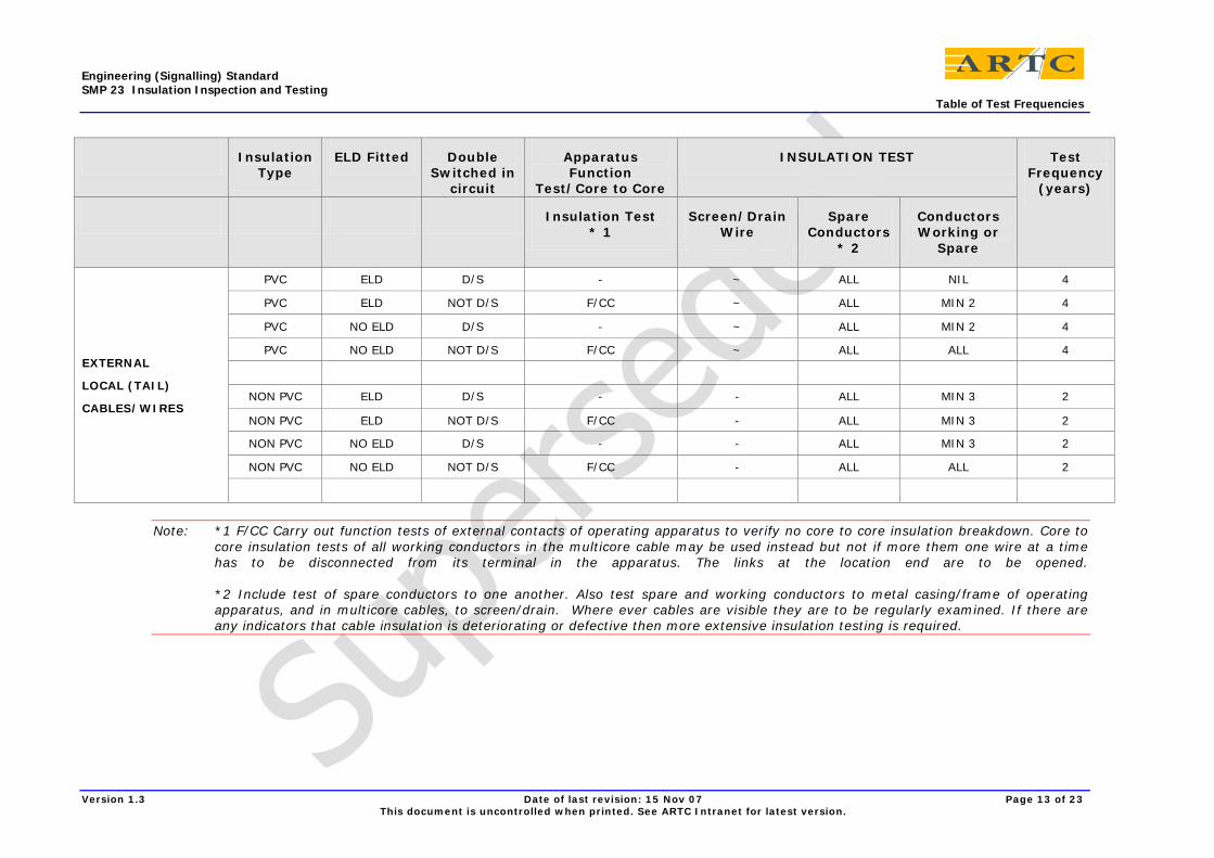
Note: *1 F/CC Carry out function tests of external contacts of operating apparatus to verify no core to core insulation breakdown. Core to core insulation tests of all working conductors in the multicore cable may be used instead but not if more them one wire at a time has to be disconnected from its terminal in the apparatus. The links at the location end are to be opened. *2 Include test of spare conductors to one another. Also test spare and working conductors to metal casing/frame of operating apparatus, and in multicore cables, to screen/drain. Where ever cables are visible they are to be regularly examined. If there are any indicators that cable insulation is deteriorating or defective then more extensive insulation testing is required.

Engineering (Signalling) Standard SMP 23 Insulation Inspection and Testing Appendix 1 – Forms (examples only)
Version 1.3 Date of last revision: 15 Nov 07 Page 14 of 23 This document is uncontrolled when printed. See ARTC Intranet for latest version.
13 Appendix 1 – Forms (examples only)

Engineering (Signalling) Standard SMP 23 Insulation Inspection and Testing Appendix 1 – Forms (examples only)
Version 1.3 Date of last revision: 15 Nov 07 Page 15 of 23 This document is uncontrolled when printed. See ARTC Intranet for latest version.

Engineering (Signalling) Standard SMP 23 Insulation Inspection and Testing Appendix 1 – Forms (examples only)
Version 1.3 Date of last revision: 15 Nov 07 Page 16 of 23 This document is uncontrolled when printed. See ARTC Intranet for latest version.

Engineering (Signalling) Standard SMP 23 Insulation Inspection and Testing Appendix 1 – Forms (examples only)
Version 1.3 Date of last revision: 15 Nov 07 Page 17 of 23 This document is uncontrolled when printed. See ARTC Intranet for latest version.

Engineering (Signalling) Standard SMP 23 Insulation Inspection and Testing Appendix 1 – Forms (examples only)
Version 1.3 Date of last revision: 15 Nov 07 Page 18 of 23 This document is uncontrolled when printed. See ARTC Intranet for latest version.

Engineering (Signalling) Standard SMP 23 Insulation Inspection and Testing Appendix 1 – Forms (examples only)
Version 1.3 Date of last revision: 15 Nov 07 Page 19 of 23 This document is uncontrolled when printed. See ARTC Intranet for latest version.

Engineering (Signalling) Standard SMP 23 Insulation Inspection and Testing Appendix 1 – Forms (examples only)
Version 1.3 Date of last revision: 15 Nov 07 Page 20 of 23 This document is uncontrolled when printed. See ARTC Intranet for latest version.

Engineering (Signalling) Standard SMP 23 Insulation Inspection and Testing Appendix 1 – Forms (examples only)
Version 1.3 Date of last revision: 15 Nov 07 Page 21 of 23 This document is uncontrolled when printed. See ARTC Intranet for latest version.

Engineering (Signalling) Standard SMP 23 Insulation Inspection and Testing Appendix 1 – Forms (examples only)
Version 1.3 Date of last revision: 15 Nov 07 Page 22 of 23 This document is uncontrolled when printed. See ARTC Intranet for latest version.

Engineering (Signalling) Standard SMP 23 Insulation Inspection and Testing Appendix 1 – Forms (examples only)
Version 1.3 Date of last revision: 15 Nov 07 Page 23 of 23 This document is uncontrolled when printed. See ARTC Intranet for latest version.