Insulated Concrete Forms (ICF) Walls Analysis and Design · 2019-03-12 · Insulated Concrete Forms...
23
Insulated Concrete Forms (ICF) Walls Analysis and Design
Transcript of Insulated Concrete Forms (ICF) Walls Analysis and Design · 2019-03-12 · Insulated Concrete Forms...
Insulated Concrete Forms (ICF) Walls Analysis and Design


Insulated Concrete Forms (ICF) Walls Analysis and Design
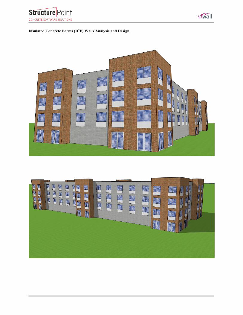
Insulating concrete form or insulated concrete form (ICF) is a system of formwork for reinforced concrete usually
made with a rigid thermal insulation that stays in place as a permanent interior and exterior substrate for walls,
floors, and roofs. The forms are interlocking modular units that are dry-stacked (without mortar) and filled
with concrete. The units lock together somewhat like Lego bricks and create a form for the structural walls or floors
of a building. ICF construction has become commonplace for both low rise commercial and high performance
residential construction as more stringent energy efficiency and natural disaster resistant building codes are adopted.
ICFs may be used with frost protected shallow foundations (FPSF). This case study focuses on the design of ICF
walls using the engineering
software program spWall. The
ICF wall under study is a wall in
a typical four-story apartment
building. The building consists of
92 apartments, 60 one-bedroom
apartment and 32 two-bedroom
apartments. The concrete floor
assembly carried by the wall
consists of 2” concrete topping
and 8” prestressed hollow core
concrete slab. The following
figure and design data section and
will serve as input for detailed
design.
Figure 1 – ICF Wall Elevation

Version: Mar-12-2019
Code
Building Code Requirements for Structural Concrete (ACI 318-14) and Commentary (ACI 318R-14)
Reference
spWall Engineering Software Program Manual v5.01, StucturePoint LLC., 2016
Design Data
Wall Material Properties
fc’ = 4,000 psi
fy = 60,000 psi
Wall Dimensions
Width = 25 ft
Height = 45 ft
Opening Size = 8 ft x 7 ft
Thickness = 6 in.
Wall Loads
PDL,floor = 1250 lb/ft
PDL,roof = 450 lb/ft
PLL,floor = 600 lb/ft
PLL,roof = 200 lb/ft
Wwind = 30 psf
Figure 2 – Wall Architectural Cross-Section
Version: Mar-12-2019
Contents
1. ICF Wall Analysis and Design – spWall Software ................................................................................................. 1
2. Wall Model Input ................................................................................................................................................... 2
3. Wall Results Contours ............................................................................................................................................ 4
4. Wall Cross-Sectional Forces .................................................................................................................................. 6
5. Wall Displacement at Critical Section .................................................................................................................... 9
6. Wall Cross-Sectional Forces at Critical Section ................................................................................................... 10
7. Wall Reactions ..................................................................................................................................................... 10
8. Wall Required Reinforcement .............................................................................................................................. 12
9. Wall Interaction Diagram and Stability Check - spColumn ................................................................................. 14
10. ICF Wall Analysis– Alternative Analysis Method ............................................................................................... 17
11. Conclusions and Observations.............................................................................................................................. 18
1
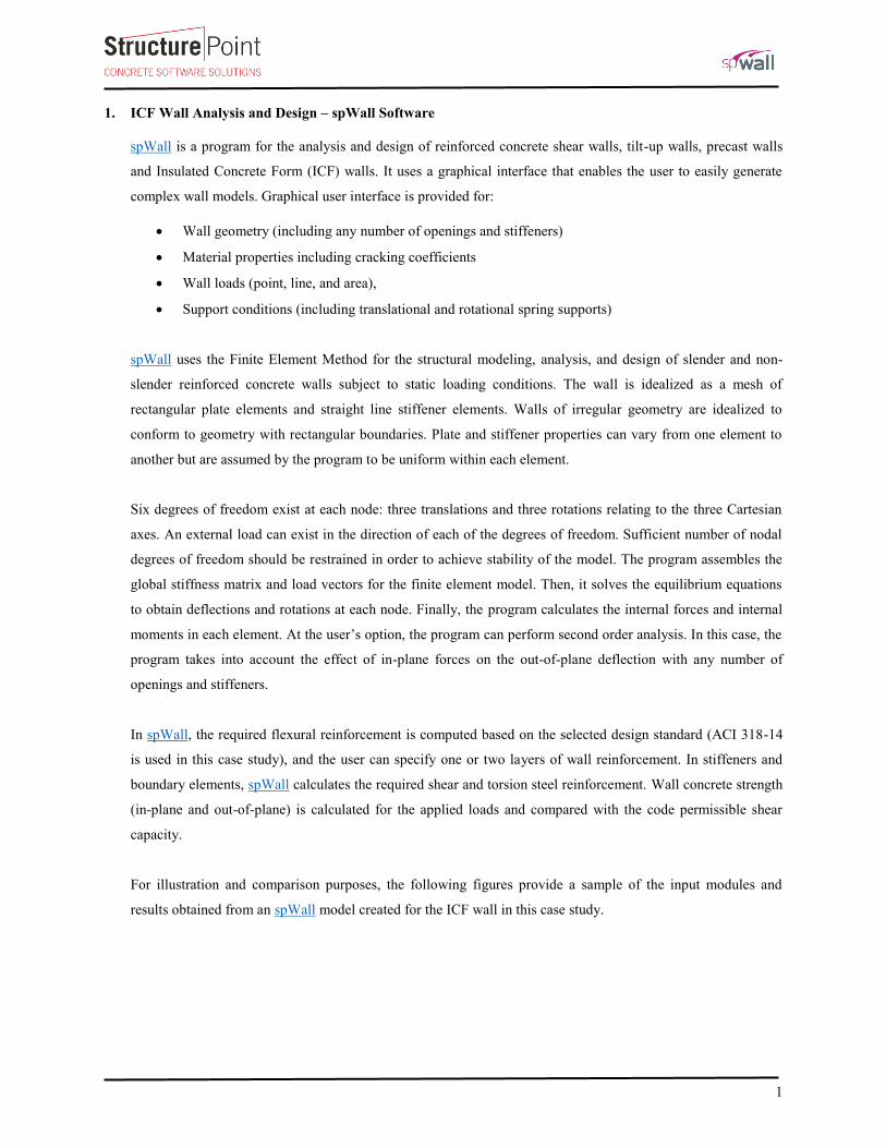
1. ICF Wall Analysis and Design – spWall Software
spWall is a program for the analysis and design of reinforced concrete shear walls, tilt-up walls, precast walls
and Insulated Concrete Form (ICF) walls. It uses a graphical interface that enables the user to easily generate
complex wall models. Graphical user interface is provided for:
Wall geometry (including any number of openings and stiffeners)
Material properties including cracking coefficients
Wall loads (point, line, and area),
Support conditions (including translational and rotational spring supports)
spWall uses the Finite Element Method for the structural modeling, analysis, and design of slender and non-
slender reinforced concrete walls subject to static loading conditions. The wall is idealized as a mesh of
rectangular plate elements and straight line stiffener elements. Walls of irregular geometry are idealized to
conform to geometry with rectangular boundaries. Plate and stiffener properties can vary from one element to
another but are assumed by the program to be uniform within each element.
Six degrees of freedom exist at each node: three translations and three rotations relating to the three Cartesian
axes. An external load can exist in the direction of each of the degrees of freedom. Sufficient number of nodal
degrees of freedom should be restrained in order to achieve stability of the model. The program assembles the
global stiffness matrix and load vectors for the finite element model. Then, it solves the equilibrium equations
to obtain deflections and rotations at each node. Finally, the program calculates the internal forces and internal
moments in each element. At the user’s option, the program can perform second order analysis. In this case, the
program takes into account the effect of in-plane forces on the out-of-plane deflection with any number of
openings and stiffeners.
In spWall, the required flexural reinforcement is computed based on the selected design standard (ACI 318-14
is used in this case study), and the user can specify one or two layers of wall reinforcement. In stiffeners and
boundary elements, spWall calculates the required shear and torsion steel reinforcement. Wall concrete strength
(in-plane and out-of-plane) is calculated for the applied loads and compared with the code permissible shear
capacity.
For illustration and comparison purposes, the following figures provide a sample of the input modules and
results obtained from an spWall model created for the ICF wall in this case study.

2
2. Wall Model Input
Figure 3 –Defining Wall Loads
3
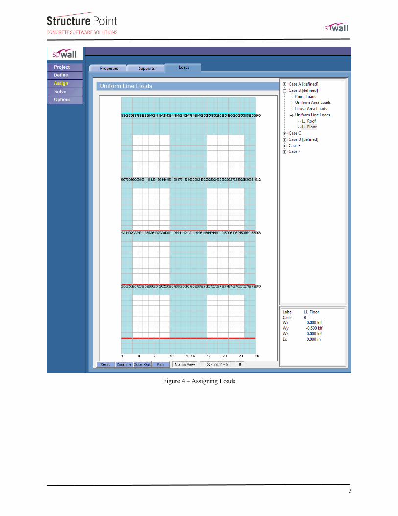
Figure 4 – Assigning Loads

4
3. Wall Results Contours
Figure 5 – Factored Axial Forces Contour Normal to Tilt-Up Wall Panel Cross-Section

5
Figure 6 –Lateral Displacement Contour (Out-of-Plane)

6
4. Wall Cross-Sectional Forces
Figure 7 – Axial Load Diagram
7
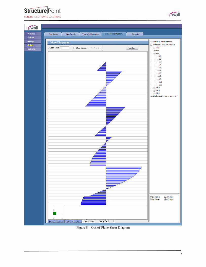
Figure 8 – Out-of-Plane Shear Diagram

8
Figure 9 –Moment Diagram
9
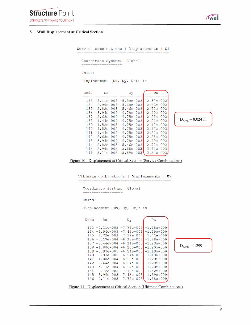
5. Wall Displacement at Critical Section
Figure 10 –Displacement at Critical Section (Service Combinations)
Figure 11 –Displacement at Critical Section (Ultimate Combinations)
Dz,avg = 0.024 in.
Dz,avg = 1.299 in.
10
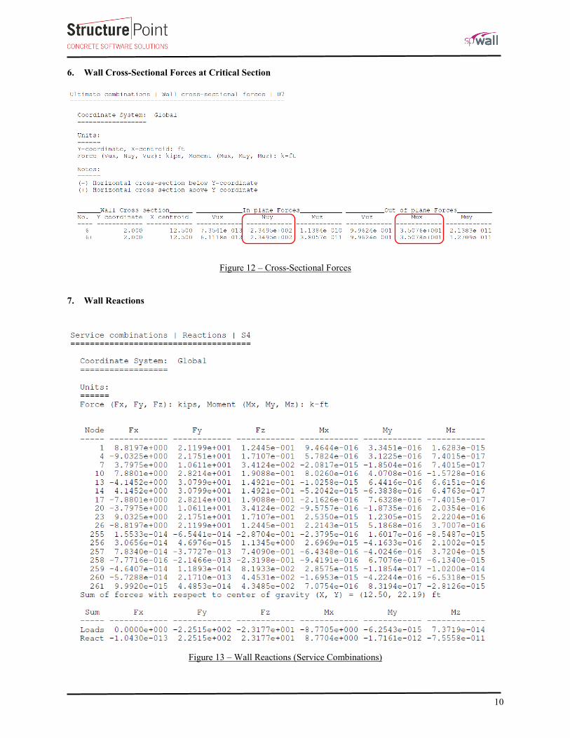
6. Wall Cross-Sectional Forces at Critical Section
Figure 12 – Cross-Sectional Forces
7. Wall Reactions
Figure 13 – Wall Reactions (Service Combinations)

11
Figure 14 – Wall Reactions (Ultimate Combinations)
12
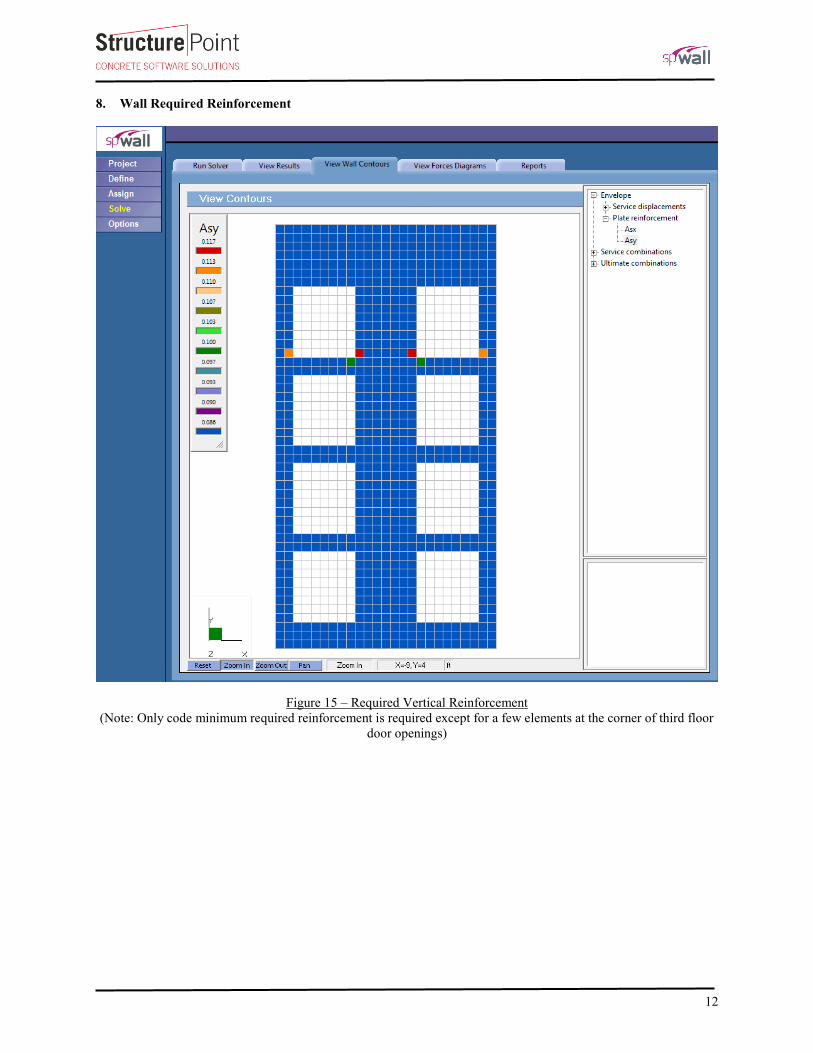
8. Wall Required Reinforcement
Figure 15 – Required Vertical Reinforcement
(Note: Only code minimum required reinforcement is required except for a few elements at the corner of third floor
door openings)
13
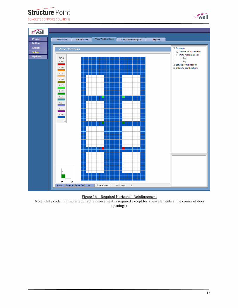
Figure 16 – Required Horizontal Reinforcement
(Note: Only code minimum required reinforcement is required except for a few elements at the corner of door
openings)
14
9. Wall Interaction Diagram and Stability Check - spColumn
For the narrow wall piers an additional strength and stability check is performed to evaluate column behavior of
the piers. The service axial loads and 1st order bending moments on the end piers at the first floor level are
obtained from spWall model. The effective length factor “k” is calculated using ACI 318-14 provisions in
section 6.2 assuming the wall is pinned at the bottom and fixed at the top in a nonsway frame can be estimated
and taken as 0.63.
Note that according to ACI 318-14 chapter 10, for “columns” with cross sections larger than required by
considerations of loading, it shall be permitted to base gross area considered, required reinforcement, and design
strength on a reduced effective area, not less than one-half the total area. More information about this topic can
be found in “Columns with Low Reinforcement – Architectural Columns” technical article in StructurePoint
Resources page. In this model the “Structural” class is used for the wall pier.

15
Figure 17 – Wall Right Leg (Pier) Interaction Diagram

16
Figure 18 – Wall End Pier Stability Check (ACI 318-14 (6.2.6))
Figure 19 – Wall End Pier Strength Check
< 1.400

17
10. ICF Wall Analysis– Alternative Analysis Method
ICF walls can be analyzed using the provisions of Chapter 11 of the ACI 318. Most walls, and especially
slender walls, are widely evaluated using the “Alternative Method for Out-of-Plane Slender Wall Analysis” in
Section 11.8. The requirements of this procedure are summarized below:
The cross section shall be constant over the height of the wall ACI 318-14 (11.8.1.1(a))
The wall can be designed as simply supported ACI 318-14 (11.8.2.1)
Maximum moments and deflections occurring at midspan ACI 318-14 (11.8.2.1)
The wall must be axially loaded ACI 318-14 (11.8.2.1)
The wall must be subjected to an out-of-plane uniform lateral load ACI 318-14 (11.8.2.1)
The wall shall be tension-controlled ACI 318-14 (11.8.1.1(b))
The reinforcement shall provide design strength greater than cracking strength ACI 318-14 (11.8.1.1(c))
Pu at the midheight section does not exceed 0.06 fc’Ag ACI 318-14 (11.8.1.1(d))
Out-of-plane deflection due to service loads including PΔ effects does not exceed lc/150
ACI 318-14 (11.8.1.1(c))
The ICF wall under study is analyzed using this method, the results obtained from the analysis are summarized
below considering minimum reinforcement being used (0.12%). More details about the use of this method can
be found in “Precast Concrete Bearing Wall Panel Design” example.
24.1 kip-ft
51
0.75 48
ua
u
u c
c cr
MM
P l
E I
ACI 318-14 (11.8.3.1d)
5.7 kip-ftr g
cr
t
f IM
y ACI 318-14 (24.2.3.5b)
12.1kip-ft 4.1kip-ft n uM M o.k. ACI 318-14 (11.5.1.1(b))
12.1 kip-ft 5.7 kip-ft n crM M o.k. ACI 318-14 (11.8.1.1(c))
Note that the wall vertical stress check shows that the wall is stressed in compression beyond the 6% limit and
the use of the alternative analysis method might not be suitable as follows:
'356 psi 0.06 240 psi u
c
g
Pf
A N.G. ACI 318-14 (11.8.1.1(d))
The maximum out-of-plane deflection (Δs) due to service lateral and eccentric vertical loads, including PΔ
effects, shall not exceed lc/150. ACI 318-14 (11.8.1.1(e))
0.009 in. 0.800 in. 150
cs
l o.k.

18
11. Conclusions and Observations
Based on the output of spWall, spColumn, and alternative analysis method results indicate the end piers are
optimally designed leaving very little margin in the strength and stability checks.
It is recommended to further refine loads and boundary conditions or increase the pier section dimensions if
higher safety margins are desired. For instance relocating the doors to achieve a 3 ft pier and possibly increasing
the thickness to 8 in. may be advisable for the first level.