INSTRUMENTATION - · PDF file2 INSTRUMENTATION Instrumentation is defined as "the art and...
33
-
Upload
truongphuc -
Category
Documents
-
view
227 -
download
2
Transcript of INSTRUMENTATION - · PDF file2 INSTRUMENTATION Instrumentation is defined as "the art and...

2
INSTRUMENTATION
Instrumentation is defined as "the art and science of measurement & control
system". Instrumentation can be used to refer to the field in which Instrument
technicians and engineers work in, or it can refer to the available methods and use
of instruments.
Instruments are devices which are used to measure attributes of physical
systems. The variable measured can include practically any measurable variable
related to the physical sciences. These variables commonly include: pressure ,
flow , temperature , level , density , viscosity , radiation , current , voltage ,
inductance , capacitance , frequency ,chemical composition , chemical properties ,
various physical properties, etc.
Instruments can often be viewed in terms of a simple input-output device. For
example, if we "input" some temperature into a thermocouple, it "outputs" some
sort of signal. (Which can later be translated into data?) In the case of this
thermocouple, it will "output" a signal in millivolts.
Process control
The purpose of process control is to reduce the variability in final products so
that legislative requirements and consumers’ expectations of product quality and
safety are meet. It also aims to reduce wastage and production costs by improving
the efficiency of processing. Simple control methods (for example, reading
thermometers, noting liquid levels in tanks, adjusting valves to control the rate of
heating or filling), have always been in place, but they have grown more
sophisticated as the scale and complexity of processing has increased. With
increased mechanization, more valves need to be opened and more motors started
or stopped.
The timing and sequencing of these activities has become more critical and
any errors by operators have led to more serious quality loss and financial
consequences. This has caused a move away from controls based on the operators’
skill and judgment to technology- based control systems. Initially, manually
operated valves were replaced by electric or pneumatic operation and switches for
motors were relocated onto control panels. Measurements of process variables,
such as levels of liquids in tanks, pressures, pH, temperatures, etc., were no longer
taken at the site of equipment, but were sent by transmitters to control panels and
gradually processes became more automated.
Automatic control has been developed and applied in almost every sector of the
industry. The impetus for these changes has come from:
• increased competition that forces manufacturers to produce a wider variety of
products more quickly
• escalating labor costs and raw material costs
• Increasingly stringent regulations that have resulted from increasing consumer
demands for standardized, safe foods and international harmonization of legislation
and standards.
For some products, new laws require monitoring, reporting and traceability of all
batches produced which has further increased the need for more sophisticated
process control.
All of these requirements have caused manufacturers to upgrade the
effectiveness of their process control and management systems. Advances in
3
microelectronics and developments in computer software technology, together with
the steady reduction in the cost of computing power, have led to the development of
very fast data processing.
This has in turn led to efficient, sophisticated, interlinked, more operator-
friendly and affordable process control systems being made available to
manufacturers. These developments are now used at all stages in a manufacturing
process, including:
• ordering and supplying raw materials
• Detailed production planning and supervision
• Management of orders, recipes and batches
• controlling the flow of product through the process
• controlling process conditions
• evaluation of process and product data (for example, monitoring temperature
profiles during heat processing or chilling
• Control of cleaning-in-place procedures
• Packaging, warehouse storage and distribution.
MEASUREMENTS
Measurements provide us with a means of describing various
phenomena in quantitative terms. It has been quoted "whatever exists in some
amount". The determination of the amount is measurement all about. There are
innumerable things in nature which have amounts. The determination of their
amounts constitutes the subject of Mechanical Measurements. The measurements
are not necessarily carried out by purely mechanical means. Quantities like
pressure, temperature, displacement, fluid flow and associated parameters,
acoustics and related parameters, and fundamental quantities like mass, length,
and time are typical of those which are within the scope of mechanical
measurements. However, in many situations, these quantities are not measured by
purely mechanical means, but more often are measured by electrical means by
transducing them into an analogous electrical quantity.
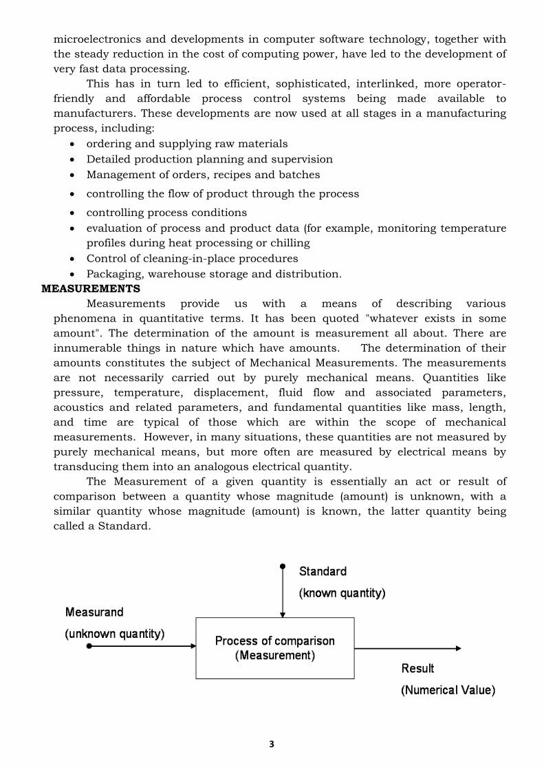
The Measurement of a given quantity is essentially an act or result of
comparison between a quantity whose magnitude (amount) is unknown, with a
similar quantity whose magnitude (amount) is known, the latter quantity being
called a Standard.
Fig. 1.1 Fundamental Measuring Process.
4
In order that the results of measurement are meaningful, the basic
requirements are:
• The standard used for comparison purposes must be accurately defined and
should be commonly acceptable,
• The standard must be of the same character as the measured (the unknown
quantity or the quantity under measurement).
• The apparatus used and the method adopted for the purposes of comparison
must be provable.
METHODS OF MEASUREMENT
The methods of measurement may be broadly classified into two categories:
1. Direct Methods
2. In-Direct Methods
Direct Methods.
In these methods, the unknown quantity (also called the measured) is directly
compared against a standard. The result is expressed as a numerical number and a
unit. Direct methods are quite common for the measurement of physical quantities
like length, mass and time.
Indirect Methods
Measurements by direct methods are not always possible, feasible and,
practicable. These methods in most of the cases are inaccurate because they involve
human factors. They are also less sensitive. Hence direct methods are not preferred
and are less commonly used.
In engineering applications Measurement Systems are used. These
measurement systems use indirect methods for measurement purposes.
A measurement system consists of a transducing element which converts the
quantity to be measured into an analogous signal. The analogous signal is then
processed by some intermediate means and is then fed to the end devices which
present the results of the measurement.
PRIMARY, SECONDARY AND TERTIARY MEASUREMENTS
Measurements may be classified as primary, secondary and tertiary based upon
whether direct or indirect methods are used.
1. Primary Measurements: - A primary measurement is one that can be made by
direct observation without involving any conversion (translation) of the measured
quantity into length.
Example: -
• The matching of two lengths, such as when determining the length of an object
with a meter rod,
• The matching of two colors, such as when judging the color of red hot metals
2. Secondary Measurements: - A secondary measurement involves only one
translation (conversion) to be done on the quantity under measurement to
convert it into a change of length. The measured quantity may be pressure of a
gas, and therefore, may not be observable. Therefore, a secondary measurement
requires,
• An instrument which translates pressure changes into length changes, and a
length scale or a standard which is calibrated in length unit’s equivalent to
known changes in pressure.

5
Therefore, in a pressure gauge, the primary signal (pressure) is transmitted to a
translator and the secondary signal (length) is transmitted to observer's eye.
3. Tertiary Measurements: -A tertiary measurement involves two translations. A
typical example of such a measurement is the measurement of temperature of
an object by thermocouple. The primary signal (temperature of object) is
transmitted to a translator which generates a voltage which is a function of the
temperature. Therefore, first translation is temperature to voltage. The voltage,
in turn, is applied to a voltmeter through a pair of wires. The second translation
is then voltage into length. The tertiary signal (length change) is transmitted to
the observer's brain. This tertiary measurement is depicted in, Fig. 2.1.
Fig. A typical tertiary measurement
INSTRUMENTS AND MEASUREMENT SYSTEMS
Measurements involve the use of instruments as a physical means of
determining quantities or variables. The instrument enables the man to determine
the value of unknown quantity or variable. A measuring instrument exists to
provide information about the physical value of some variable being measured. In
simple cases, an instrument consists of a single unit which gives an output reading
or signal according to the unknown variable (measured) applied to it. In more
complex measurement situations, a measuring instrument may consist of several
separate elements. These elements may consist of transducing elements which
convert the measured to an analogous form. The analogous signal is then processed
by some intermediate means and then fed to the end devices to present the results
of the measurement for the purposes of display, record and control. Because of this
modular nature of the elements within it, it is common to refer the measuring
instrument as a measurement system.
6
MECHANICAL, ELECTRICAL AND ELECTRONIC INSTRUMENTS
The history of development of instruments encompasses three phases of
instruments, viz.: (i) mechanical instruments, (it) electrical instruments and (iii)
electronic instruments.
The three essential elements in modern instruments are:
• A detector,
• An intermediate transfer device, and
• An indicator, recorder or a storage device.
Mechanical Instruments. These instruments are very reliable for static and stable
conditions. Major disadvantage is unable to respond rapidly to measurements of
dynamic and transient conditions. This is due to the fact that these instruments
have moving parts that are rigid, heavy and bulky and consequently have a large
mass. Mass presents inertia problems and hence these instruments cannot follow
the rapid changes which are involved in dynamic measurements. Thus it would be
virtually impossible to measure a 50Hz voltage by using a mechanical instrument
but it is relatively easy to measure a slowly varying pressure using these
instruments. Another disadvantage of mechanical instruments is that most of them
are a potential source of noise and cause noise pollution.
Electrical Instruments. Electrical methods of indicating the output of detectors are
more rapid than mechanical methods. Electrical system normally depends upon a
mechanical meter movement as indicating device. This mechanical movement has
some inertia and therefore these instruments have a limited time (and hence,
frequency) response. For example, some electrical recorders can give full scale
response in 0.2 s, the majority of industrial recorders have responses of 0.5 to 24 s.
Electronics Instruments.: The necessity to step up response time and also the
detection of dynamic changes in certain parameters, which require the Monitoring
time of the order of ms and many a times have led to the design of today's electronic
instruments and their associated circuitry. These instruments require use of
semiconductor devices. Since in electronic devices, the only movement involved is
that of electrons, the response time is extremely small on account of very small
inertia of electrons. For example, a Cathode Ray Oscilloscope (CRO) is capable of
following dynamic and transient changes of the order of a few ns (10-9 s).
Another advantage of using electronic devices is that very weak signals can be
detected by using pre-amplifiers and amplifiers. Therefore, most importance of the
electronic instruments is the power amplification provided by the electronic
amplifiers, which results in higher sensitivity. This is particularly important in the
area of Bio-instrumentation since Bio-electric potentials are very weak i.e., lower
than 1 mV. Therefore, these signals are too small to operate electro-mechanical
devices like recorders and they must be amplified. Additional power may be fed into
the system to provide an increased power output beyond that of the input. Another
advantage of electronic instruments is the ability to obtain indication at a remote
location which helps in monitoring inaccessible or hazardous locations. The most
important use of electronic instrument is their usage in measurement of non-
electrical quantities, where the non-electrical quantity is converted into electrical
form through the use of transducers.
Electronic instruments are light, compact, have a high degree of reliability

7
and their power consumption is very low. Communications is a field which is
entirely dependent upon the electronic instruments and associated apparatus.
Space communications, especially, makes use of air borne transmitters and
receivers and job of interpreting the signals is left entirely to the electronic
instruments.
In general, electronic instruments have
• a higher sensitivity
• a faster response,
• a greater flexibility,
• lower weight,
• Lower power consumption and
• a higher degree of reliability
FUNCTIONAL ELEMENTS OF MEASUREMENT SYSTEMS
A generalized 'Measurement System' consists of the following:
1. Basic Functional Elements, and
2. Auxiliary Functional Elements.
Basic Functional Elements are those that form the integral parts of all instruments.
They are the following:
1. Transducer Element that senses and converts the desired input to a more
convenient and practicable form to be handled by the measurement system.
2. Signal Conditioning or Intermediate Modifying Element for manipulating
/processing the output of the transducer in a suitable form.
3. Data Presentation Element for giving the information about the measured or
measured variable in the quantitative form.
Auxiliary Functional Elements are those which may be incorporated in a particular
system depending on the type of requirement, the nature of measurement
technique, etc. They are:
1. Calibration Element to provide a built-in calibration facility.
2. External Power Element to facilitate the working of one or more of the
elements like the transducer element, the signal conditioning element, the
data processing element or the feedback element.
3. Feedback Element to control the variation of the physical quantity that is being
measured. In addition, feedback element is provided in the null- seeking
potentiometric or Wheatstone bridge devices to make them automatic or self-
balancing.
4. Microprocessor Element to facilitate the manipulation of data for the purpose
of simplifying or accelerating the data interpretation. It is always used in
conjunction with analog-to-digital converter which is incorporated in the
signal conditioning element.
Transducer Element
Normally, a transducer senses the desired input in one physical form and
converts it to an output in another physical form. For example, the input variable to
the transducer could be pressure, acceleration or temperature and the output of the
transducer may be displacement, voltage or resistance change depending on the
type of transducer element. Sometimes the dimensional units of the input and
output signals may be same. In such cases, the functional element is termed a
transformer.

CLASSIFICATION OF INSTRUMENTS
Instruments may be classified according to their application, mode of operation,
manner of energy conversion, and nature of output signal and so on. The
instruments commonly used in practice may be broadly categorized as follows:
1. Deflection and Null Types
• A deflection type instrument is that in which the physical effect generated by
the measuring quantity produces an equivalent opposing effect in some part of
the instrument which in turn is closely related to some variable like mechanical
displacement or deflection in the instrument. For example, the unknown weight
of an object can be easily obtained by the deflection of a spring caused by it on
the spring balance as shown in Fig. Similarly, in a common Bourdon gauge, the
pressure to be measured acts on the C-type spring of the gauge, which deflects
and produces an internal spring force to counter balance the force generated by
the applied pressure. Deflection instruments are simple in construction and
operation.
Fig. a typical spring balance – A deflection type weight measuring instrument
• A null type instrument is the one that is provided with either a manually
operated or automatic balancing device that generates an equivalent
opposing effect to nullify the physical effect caused by the quantity to be
measured. The equivalent null-causing effect in turn provides the measure of
the quantity. Consider a simple situation of measuring the mass of an object
by means of an equal-arm beam balance. An unknown mass, when placed in
the pan, causes the beam and pointer to deflect. Masses of known values are
placed on the other pan till a balanced or null condition is obtained by
means of the pointer. The main advantage of the null-type devices is that
they do not interfere with the state of the measured quantity and thus
measurements of such instruments are extremely accurate.
2. Manually Operated and Automatic Types
Any instrument which requires the services of human operator is a
manual type of instrument. The instrument becomes automatic if the manual
operation is replaced by an auxiliary device incorporated in the instrument. An
automatic instrument is usually preferred because the dynamic response of
such an instrument is fast and also its operational cost is considerably lower
than that of the corresponding manually operated instrument.
3. Analog and Digital Types
Analog instruments are those that present the physical variables of
interest in the form of continuous or step less variations with respect to time.
These instruments usually consist of simple functional elements. Therefore, the
majority of present-day instruments are of analog type as they generally cost
less and are easy to maintain and repair.
On the other hand, digital instruments are those in which the physical
variables are represented by digital quantities which are discrete and vary in
steps. Further, each digital number is a fixed sum of equal steps which is
defined by that number. The relationship of the digital outputs with respect to
time gives the information about the magnitude and the nature of the input
data.
4. Self-Generating and Power-Operated Types
In self-generating (or passive) instruments, the energy requirements of the
instruments are met entirely from the input signal. On the other hand, power-
operated (or active) instruments are those that require some source of auxiliary
power such as compressed air, electricity, hydraulic supply, etc. for their
operation.
5. Contacting and Non-Contacting Types
A contacting type of instrument is one that is kept in the measuring
medium itself. A clinical thermometer is an example of such instruments.
On the other hand, there are instruments that are of non-contacting or
proximity type. These instruments measure the desired input even though they
are not in close contact with the measuring medium. For example, an optical
pyrometer monitors the temperature of, say, a blast furnace, but is kept out of
contact with the blast furnace. Similarly, a variable reluctance tachometer,
which measures the rpm of a rotating body, is also a proximity type of
instrument.
An intelligent or smart instrument may include some or all of the
following:
1. The output of the transducer in electrical form.
2. The output of the transducer should be in digital form. Otherwise it has
to be converted to the digital form by means of analog-to-digital converter
(A-D converter).
3. Interface with the digital computer.
4. Software routines for noise reduction, error estimation, self-calibration,
gain adjustment, etc.
5. Software routines for the output driver for suitable digital display or to
provide serial ASCII coded output.
INDICATING, RECORDING AND DISPLAY ELEMENTS
Introduction
The final stage in a measurement system comprises an indicating and a
recording element, which gives an indication of the input being measured.
These elements may also be of analog or digital type, depending on whether the
indication or recording is in a continuous or discrete manner. Conventional
voltmeters and ammeters are the simplest examples of analog indicating
instruments, working on the principle of rotation of a coil through which a
current pass, the coil being in a magnetic field.
Digital voltmeters (DVMs) are commonly used as these are convenient for
indication and are briefly described here. Cathode ray oscilloscopes (CROs)
have also been widely used for indicating these signals.
Recording instruments may be galvanometric, potentiometric, servo types
or magnetic tape recorder types. In addition to analog recorders, digital
recorders including digital printers, punched cards or tape recording elements
are also available.
In large-scale systems, data loggers incorporating digital computers are
extensively used for data recording. The present-day availability of memory
devices has made the problem of data storage simpler than was previously
possible.
DIGITAL VOLTMETERS (DVMS)
Digital voltmeters convert analog signals into digital presentations which
may be as an indicator or may give an electrical digital output signal. DVMs
measure dc voltage signals. However, other variables like ac voltages,
Resistances, current, etc. may also be measured with appropriate elements
preceding the input of the DVM.
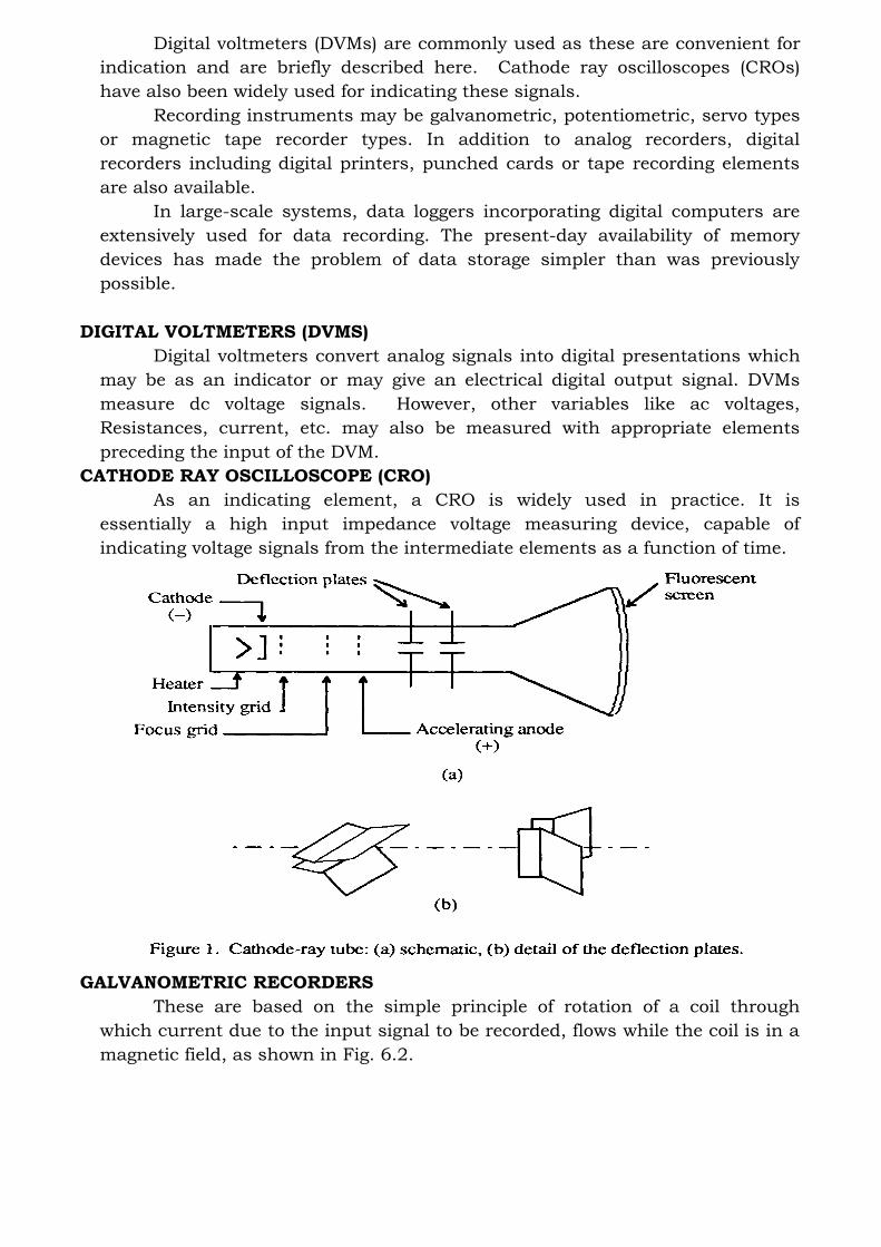
CATHODE RAY OSCILLOSCOPE (CRO)
As an indicating element, a CRO is widely used in practice. It is
essentially a high input impedance voltage measuring device, capable of
indicating voltage signals from the intermediate elements as a function of time.
GALVANOMETRIC RECORDERS
These are based on the simple principle of rotation of a coil through
which current due to the input signal to be recorded, flows while the coil is in a
magnetic field, as shown in Fig. 6.2.
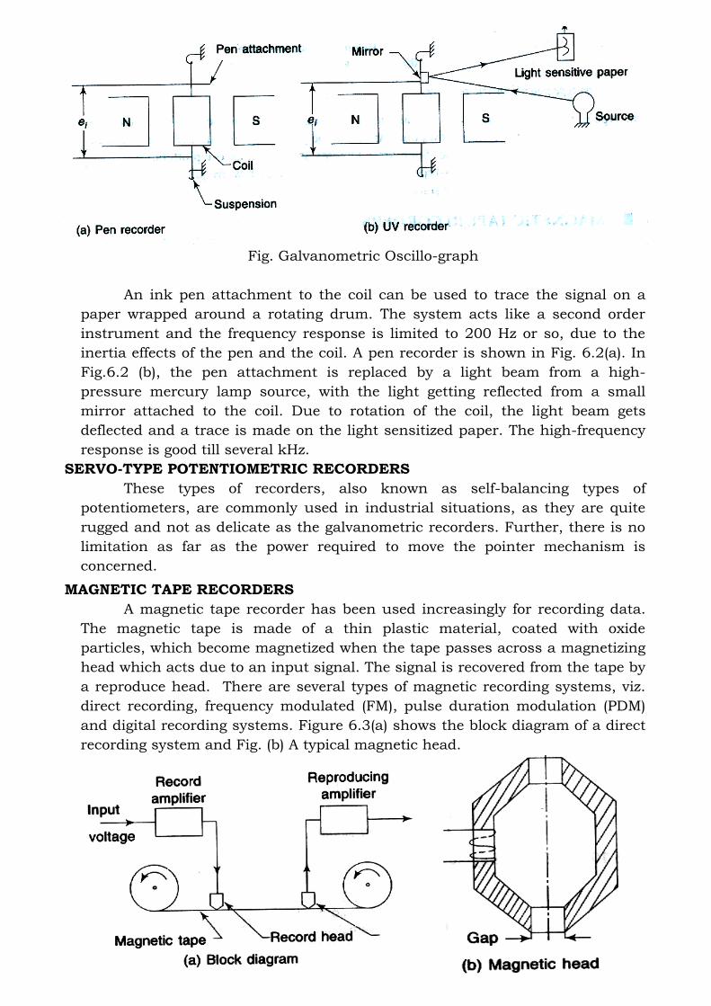
Fig. Galvanometric Oscillo-graph
An ink pen attachment to the coil can be used to trace the signal on a
paper wrapped around a rotating drum. The system acts like a second order
instrument and the frequency response is limited to 200 Hz or so, due to the
inertia effects of the pen and the coil. A pen recorder is shown in Fig. 6.2(a). In
Fig.6.2 (b), the pen attachment is replaced by a light beam from a high-
pressure mercury lamp source, with the light getting reflected from a small
mirror attached to the coil. Due to rotation of the coil, the light beam gets
deflected and a trace is made on the light sensitized paper. The high-frequency
response is good till several kHz.
SERVO-TYPE POTENTIOMETRIC RECORDERS
These types of recorders, also known as self-balancing types of
potentiometers, are commonly used in industrial situations, as they are quite
rugged and not as delicate as the galvanometric recorders. Further, there is no
limitation as far as the power required to move the pointer mechanism is
concerned.
MAGNETIC TAPE RECORDERS
A magnetic tape recorder has been used increasingly for recording data.
The magnetic tape is made of a thin plastic material, coated with oxide
particles, which become magnetized when the tape passes across a magnetizing
head which acts due to an input signal. The signal is recovered from the tape by
a reproduce head. There are several types of magnetic recording systems, viz.
direct recording, frequency modulated (FM), pulse duration modulation (PDM)
and digital recording systems. Figure 6.3(a) shows the block diagram of a direct
recording system and Fig. (b) A typical magnetic head.

Fig Direct recording system
DIGITAL RECORDER OF MEMORY TYPE
Another Development in digital recording is to replace the magnetic tape
with a large semiconductor memory, as shown in Fig.
Fig Digital waveform recorder with memory
The analog input signal is sampled and converted to digital form by an A-D
converter. The signal is stored in the memory and converted to analog or digital
outputs for presentation as desired.
DATA ACQUISITION SYSTEMS
For large-scale data recording, data acquisition systems or loggers are
employed, e.g. in a power plant, the input signals, like temperatures, pressures,
speeds, flow rates, etc. from a number of locations, may have to be recorded
periodically or continuously. In such cases, such systems are employed.
The data acquisition systems used are usually of digital type using a
digital computer and may have multiple channels for measurement of various
physical variables, the number of channels may be up to 100 or even more.
Figure 6.5 shows a large-scale data acquisition system with the sensor
being of analog types. After signal conditioning including amplification, a
multiplexer is used, which is essentially a switching device, enabling each input
to be sampled in turn. A sample and hold (S and H) device is used where an
analog-to-digital converter (A - D converter) is employed and where the analog
signal might change during conversion. The S and H device employs a
capacitor, which is charged up to the analog signal value which is held at its
value, till called by the A-D converter.
The computer controls the addressing and data input and processes the
signals as desired, for display, printing and storage.
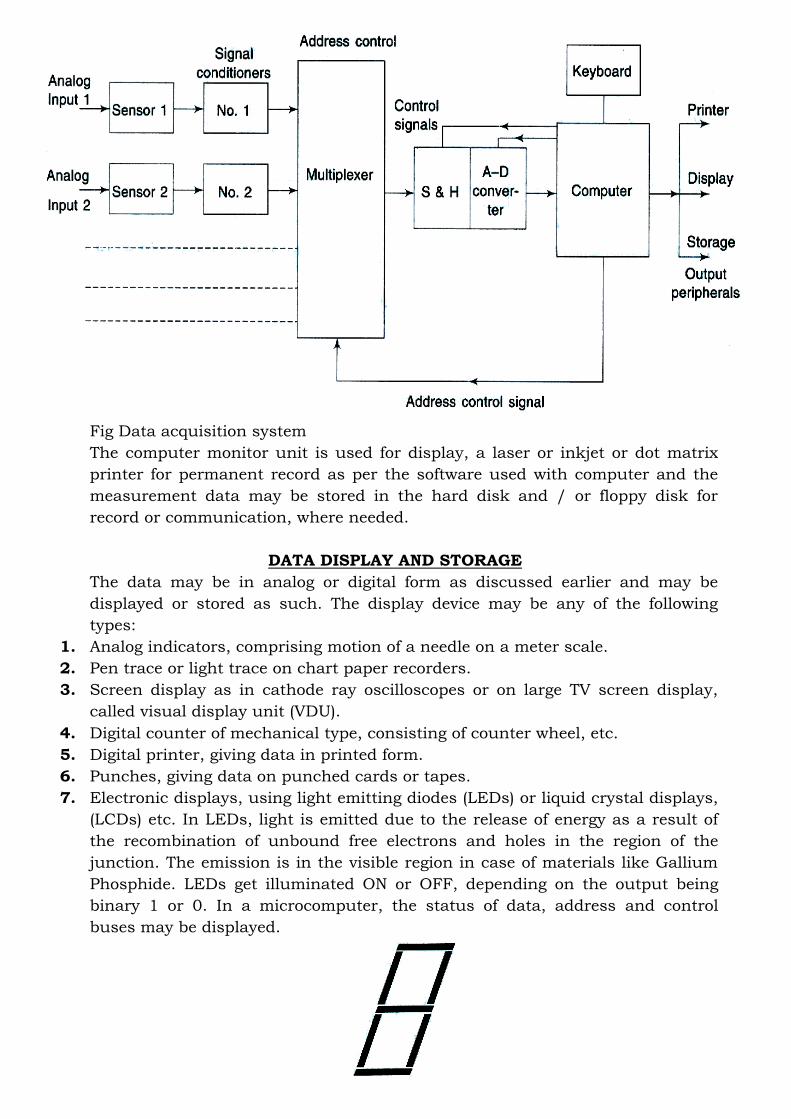
Fig Data acquisition system
The computer monitor unit is used for display, a laser or inkjet or dot matrix
printer for permanent record as per the software used with computer and the
measurement data may be stored in the hard disk and / or floppy disk for
record or communication, where needed.
DATA DISPLAY AND STORAGE
The data may be in analog or digital form as discussed earlier and may be
displayed or stored as such. The display device may be any of the following
types:
1. Analog indicators, comprising motion of a needle on a meter scale.
2. Pen trace or light trace on chart paper recorders.
3. Screen display as in cathode ray oscilloscopes or on large TV screen display,
called visual display unit (VDU).
4. Digital counter of mechanical type, consisting of counter wheel, etc.
5. Digital printer, giving data in printed form.
6. Punches, giving data on punched cards or tapes.
7. Electronic displays, using light emitting diodes (LEDs) or liquid crystal displays,
(LCDs) etc. In LEDs, light is emitted due to the release of energy as a result of
the recombination of unbound free electrons and holes in the region of the
junction. The emission is in the visible region in case of materials like Gallium
Phosphide. LEDs get illuminated ON or OFF, depending on the output being
binary 1 or 0. In a microcomputer, the status of data, address and control
buses may be displayed.

Fig Seven-segment display
Using LEDs, a seven-segment display can be made, which would display most
of the desired characters. LCDs are made from organic molecules, which flow
like liquids and have crystal like characteristics, appearing dark or bright,
depending on the application of a certain voltage range across the crystal. The
seven segment displays may also be made up of LCDs.
8. The storage of data may be on cards, magnetic tapes, disks core memories, etc.
Figure shows a floppy disk storage system, which is of magnetic type.
The digital data on the disk is recorded in concentric-circles, known as
tracks. The disk is divided into sectors which are numbered and can hold a
number of characters. The formatting of the disk is done to identify the tracks
and the sectors. A reference hole is shown for numbering the start of the tracks.
Fig Floppy disk storage system
A read/write head is used for each disk surface and heads and moved by
an actuator. The disk is rotated and data is read or written. In some disks, the
head is in contact with the disk surface which in others, there is a small gap.
The hard disks are sealed unit and have a large number of tracks and
sectors and store much more data
9. The permanent record of data from a computer may be made on a dot matrix or
inkjet or laser printer.
The dot matrix printer is of impact type where dots are formed by wires,
controlled by solenoids pressed on ink ribbons onto the paper. The inkjet
printer is of non-impact type, in which a stream of fine ink particles is
produced. The particles can get deflected by two sets of electrodes is the
horizontal and vertical planes. The image of the characters is thus formed.
The laser printer has high resolution and works according to the principle
as shown in Fig. The drum is coated with an organic chemical coating which is
an insulator and gets charged as it passes the charging wire
1. The laser light is reflected from the white regions of the image or the characters to
be produced, to the drum, making these portions conducting. The toner gets
attracted to the charged regions of the drum. The paper is given a charge by the
charging wire
2. which is higher than that on the drum, transferring the toner to the paper, creating

the impressions of the character or images. Further, the impressions get
permanent by heating.
Fig View of a laser printer
ERRORS IN PERFORMANCE PARAMETERS
The various static performance parameters of the instruments are obtained by
performing certain specified tests depending on the type of instrument, the
nature of the application, etc. Some salient static performance parameters are
periodically checked by means of a static calibration. This is accomplished by
imposing constant values of 'known' inputs and observing the resulting outputs.
No measurement can be made with perfect accuracy and precision. Therefore, it
is instructive to know the various types of errors and uncertainties that are in
general, associated with measurement system. Further, it is also important to
know how these errors are propagated.
Types of Errors
Error is defined as the difference between the measured and the true value (as
per standard). The different types of errors can be broadly classified as follows.
1. Systematic or Cumulative Errors
Such errors are those that tend to have the same magnitude and sign for
a given set of conditions. Because the algebraic sign is the same, they tend to
accumulate and hence are known as cumulative errors. Since such errors alter
the instrument reading by a fixed magnitude and with same sign from one
reading to another, therefore, the error is also commonly termed as instrument
bias.
2. Instrument errors:
Certain errors are inherent in the instrument systems. These may be
caused due to poor design / construction of the instrument. Errors in the
divisions of graduated scales, inequality of the balance arms, irregular spring’s
tension, etc., cause such errors. Instrument errors can be avoided by (i)
selecting a suitable instrument for a given application, (ii) applying suitable
correction after determining the amount of instrument error, and (iii) calibrating
the instrument against a suitable standard.
3. Environmental errors:
These types of errors are caused due to variation of conditions external to
the measuring device, including the conditions in the area surrounding the
instrument. Commonly occurring changes in environmental conditions that
may affect the instrument characteristics are the effects of changes in
temperature, barometric pressure, humidity, wind forces, magnetic or
electrostatic fields, etc.
4. Loading errors
Such errors are caused by the act of measurement on the physical system
being tested. Common examples of this type are:
I. introduction of additional resistance in the circuit by the measuring
milliammeter which may alter the circuit current by significant amount,
II. an obstruction type flow meter may partially block or disturb the flow
conditions and consequently the flow rate shown by the meter may not be
same as before the meter installation, and
III. Introduction of a thermometer alters the thermal capacity of the system and
thereby changes the original state of the system which gives rise to loading
error in the temperature measurement.
5. Accidental or Random Errors
These errors are caused due to random variations in the parameter or the
system of measurement. Such errors vary in magnitude and may be either
positive or negative on the basis of chance alone. Since these errors are in either
direction, they tend to compensate one another. Therefore, these errors are also
called chance or compensating type of errors. The following are some of the
main contributing factors to random error. Inconsistencies associated with
accurate measurement of small quantities.
The outputs of the instruments become inconsistent when very accurate
measurements are being made. This is because when the instruments are built
or adjusted to measure small quantities, the random errors (which are of the
order of the measured quantities) become noticeable.
6. Presence of certain system defects
System defects such as large dimensional tolerances in mating parts and
the presence of friction contribute to errors that are either positive or negative
depending on the direction of motion. The former causes backlash error and the
latter cause’s slackness in the meter bearings.
7. Effect of unrestrained and randomly varying parameters
Chance errors are also caused due to the effect of certain uncontrolled
disturbances which influence the instrument output. Line voltage fluctuations,
vibrations of the instrument supports, etc. are common examples of this type.
8. Miscellaneous Type of Gross Errors
There are certain other errors that cannot be strictly classified as either
systematic or random as they are partly systematic and partly random.
Therefore, such errors are termed miscellaneous type of gross errors.
9. Personal or human errors
These are caused due to the limitations in the human senses. For
example, one may sometimes consistently read the observed value either high or
low and thus introduce systematic errors in the results. While at another time
one may record the observed value slightly differently than the actual reading
and consequently introduce random error in the data.
10. Errors due to faulty components / adjustments
Sometimes there is a misalignment of moving parts, electrical leakage,
poor optics, etc. in the measuring system.
11. Improper application of the instrument
Errors of this type are caused due to the use of instrument in conditions
which do not conform to the desired design / operating conditions. For
example, extreme vibrations, mechanical shock or pick-up due to electrical
noise could introduce
MEASUREMENT OF TEMPERATURE
Temperature is measured by observing the effect that temperature
variation causes on the measuring device. Temperature measurement methods
can be broadly classified as follows:
1. Non-electrical methods,
2. Electrical methods, and
3. Radiation methods.
NON-ELECTRICAL METHODS
The non-electrical methods of temperature measurement can be based on
anyone of the following principles:
1. Change in the physical state,
2. Change in the chemical properties, and
3. Change in the physical properties.
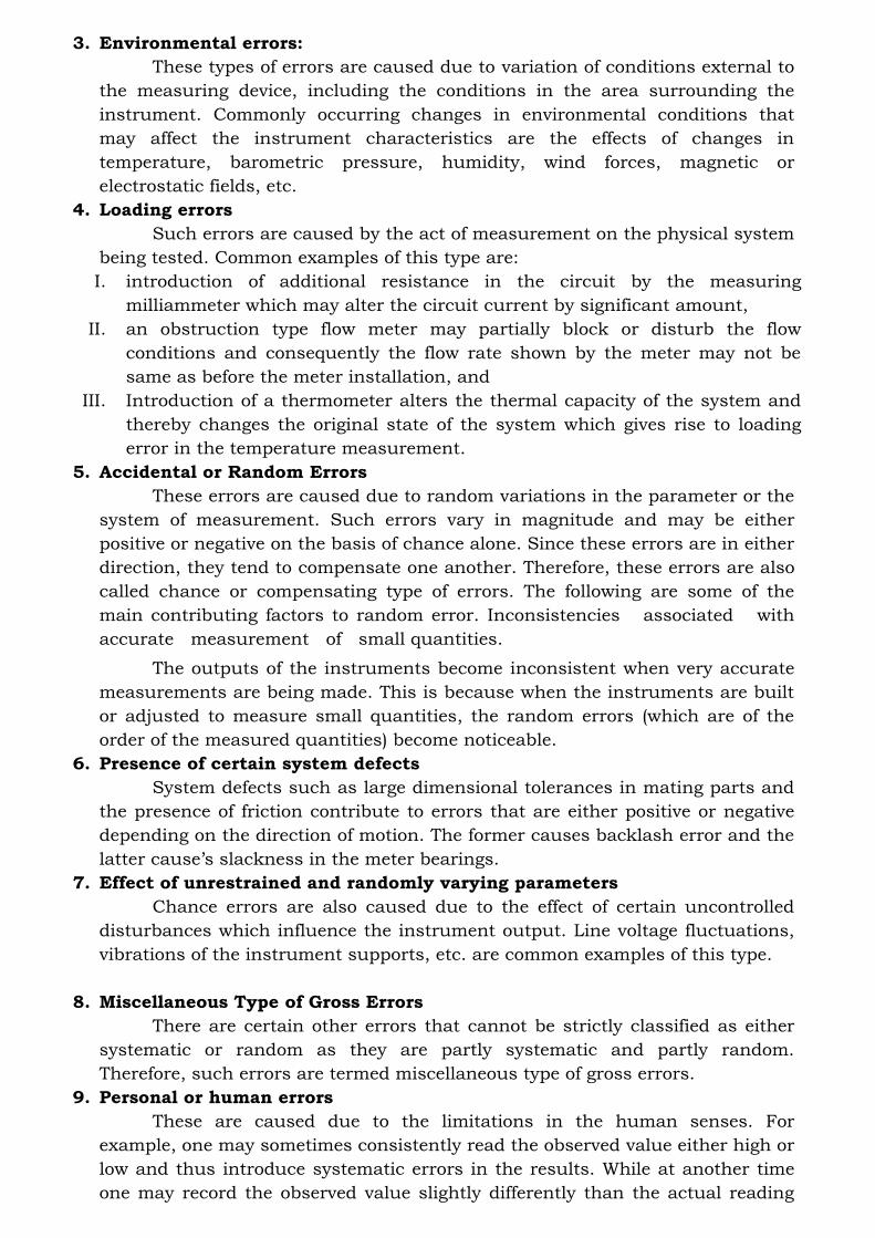
BIMETALLIC THERMOMETER
This type of thermometer also employs the principle of solid expansion
and consists of a ‘bimetal’ strip usually in the form of a cantilever beam
[Fig.15.1 (a)]. This comprises strips of two metals, having different coefficients of
thermal expansion, welded or riveted together so that relative motion between
them is prevented. An increase in temperature causes the deflection of the free
end of the strip as shown in Fig.15.1 (b), assuming that metal A has the higher
coefficient of expansion.
The deflection with the temperature is nearly linear, depending mainly on
the coefficient of linear thermal expansion. Invar is commonly employed as the
low expansion metal. This is an iron- nickel alloy containing 36% nickel. Its
coefficient of thermal expansion is around 1/20th of the ordinary metals. Brass
is used as high expansion material for the measurement of low temperatures,
whereas nickel alloys are used when higher temperatures have to be measured.
A plain bimetallic strip is somewhat insensitive, but the sensitivity is improved
by using a longer strip in a helical form as shown in Fig
Bimetallic thermometers are usually employed in the range of -30 to 550
°C. Inaccuracies of the order of ± 0.5 to ± 1.0% of full-scale deflection are
expected in bimetallic thermometers of high accuracies.
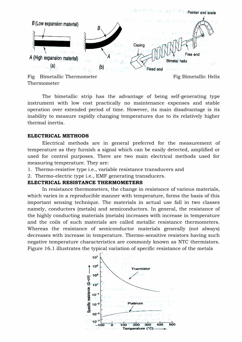
Fig Bimetallic Thermometer Fig Bimetallic Helix
Thermometer
The bimetallic strip has the advantage of being self-generating type
instrument with low cost practically no maintenance expenses and stable
operation over extended period of time. However, its main disadvantage is its
inability to measure rapidly changing temperatures due to its relatively higher
thermal inertia.
ELECTRICAL METHODS
Electrical methods are in general preferred for the measurement of
temperature as they furnish a signal which can be easily detected, amplified or
used for control purposes. There are two main electrical methods used for
measuring temperature. They are:
1. Thermo-resistive type i.e., variable resistance transducers and
2. Thermo-electric type i.e., EMF generating transducers.
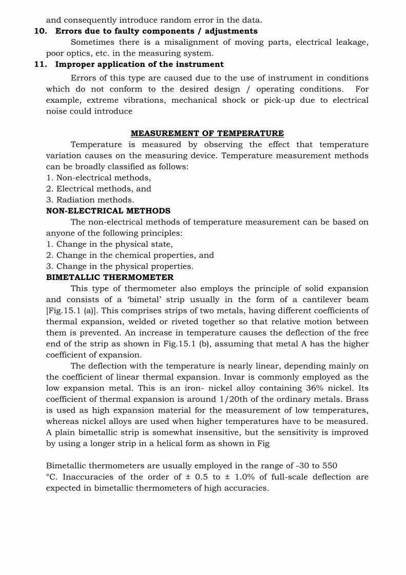
ELECTRICAL RESISTANCE THERMOMETERS
In resistance thermometers, the change in resistance of various materials,
which varies in a reproducible manner with temperature, forms the basis of this
important sensing technique. The materials in actual use fall in two classes
namely, conductors (metals) and semiconductors. In general, the resistance of
the highly conducting materials (metals) increases with increase in temperature
and the coils of such materials are called metallic resistance thermometers.
Whereas the resistance of semiconductor materials generally (not always)
decreases with increase in temperature. Thermo-sensitive resistors having such
negative temperature characteristics are commonly known as NTC thermistors.
Figure 16.1 illustrates the typical variation of specific resistance of the metals
(platinum for example) and the NTC thermistor.
Fig Resistance- temperature characteristics of platinum and a typical NTC
thermistor
METALLIC RESISTANCE THERMOMETERS OR RESISTANCE-
TEMPERATURE DETECTORS (RTDS)
Metals such as platinum, copper, tungsten and nickel exhibit small
increases in resistance as the temperature rises because they have a positive
temperature coefficient of resistance. Platinum is a very widely used sensor and
its operating range is from 4K to 1064 °C. Because it provides extremely
reproducible output, it is used in establishing International Practical
Temperature Scale from 13.81 K to 961.93 °C. However, for the measurement of
lower temperatures up to 600°C, RTD sensor is made of nickel.
Metallic resistance thermometers are constructed in many forms, but the
temperature sensitive element is usually in the form of a coil of fine wire
supported in a stress-free manner. A typical construction is shown in Fig. 16.2,
where the wire of metal is wound on the grooved hollow insulating ceramic
former and covered with protective cement.
Fig Construction of a platinum resistance thermometer (PRT)
THERMO-ELECTRIC SENSORS / THERMOCOUPLE
The most common electrical method of temperature measurement uses
the thermo-electric sensor, also known as the thermocouple (TC). The
thermocouple is a temperature transducer that develops an EMF which is a
function of the temperature between hot junction and cold junction. The
construction of a thermocouple is quite simple. It consists of two wires of
different metals twisted and brazed or welded together with each wire covered
with insulation which may be either.
1. Mineral (magnesium oxide) insulation for normal duty, or
2. Ceramic insulation for heavy duty.
PRESSURE MEASUREMENT
INTRODUCTION
Pressure means force per unit area, exerted by a fluid on the surface of the
container.
Pressure measurements are one of the most important measurements made
in industry especially in continuous process industries such as chemical
processing, food and manufacturing. The principles used in measurement of
pressure are also applied in the measurement of temperature, flow and liquid
level. Pressure is represented as force per unit area. Fluid pressure is on
account of exchange of momentum between the molecules of the fluid and a
container wall.
Static and Dynamic Pressures
When a fluid is in equilibrium, the pressure at a point is identical in all
directions and is independent of orientation. This is called static pressure.
However, when pressure gradients occur within a continuum (field) of
pressure, the attempt to restore equilibrium results in fluid flow from regions of
higher pressure to regions of lower pressure. In this case the pressures are no
longer independent of direction and are called dynamic pressures.
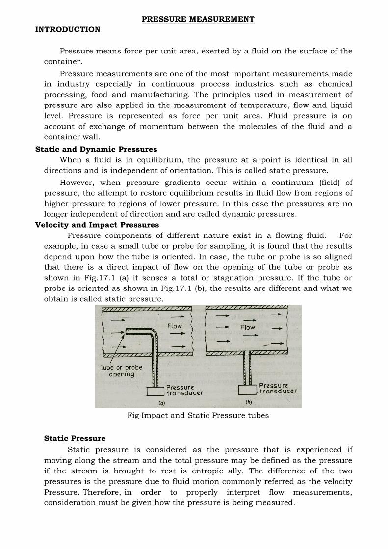
Velocity and Impact Pressures
Pressure components of different nature exist in a flowing fluid. For
example, in case a small tube or probe for sampling, it is found that the results
depend upon how the tube is oriented. In case, the tube or probe is so aligned
that there is a direct impact of flow on the opening of the tube or probe as
shown in Fig.17.1 (a) it senses a total or stagnation pressure. If the tube or
probe is oriented as shown in Fig.17.1 (b), the results are different and what we
obtain is called static pressure.
Fig Impact and Static Pressure tubes
Static Pressure
Static pressure is considered as the pressure that is experienced if
moving along the stream and the total pressure may be defined as the pressure
if the stream is brought to rest is entropic ally. The difference of the two
pressures is the pressure due to fluid motion commonly referred as the velocity
Pressure. Therefore, in order to properly interpret flow measurements,
consideration must be given how the pressure is being measured.

Absolute pressure
Absolute pressure means the fluid pressure above the reference value of a
perfect vacuum or the absolute zero pressure.
Gauge pressure
It represents the difference between the absolute pressure and the local
atmospheric pressure.
Vacuum
Vacuum on the other hand, represents the amount by which
atmospheric pressure exceeds the absolute pressure.
Fig Various Pressure Terms used in Pressure Measurement
TYPES OF PRESSURE MEASUREMENT DEVICES
A number of devices can be used for measurement of pressure. In industrial
applications pressure is normally measured by means of indicating Gauges and
recorders. These instruments are
• Mechanical,
• Electromechanical
• Electrical or electronic in operation
(i) Mechanical Pressure Measuring Instruments.
Pressure can be easily transduced to force by allowing it to act on a known area.
Therefore, basic methods of measuring force and pressure are essentially the
same except for the pressures in the high vacuum region. Mechanical
instruments used for pressure measurement are based on comparison with
known dead weights acting on known areas or on the deflection of elastic
elements subjected to unknown pressures.
Instruments using this principle include manometers. And the elastic members
used are Bourdon tubes, bellows and diaphragms.
(ii) Electromechanical Instruments. These instruments generally employ
mechanical means for detecting pressure and electrical means for indicating or
recording pressure. Electromechanical instruments are very well suitable for
dynamic measurements as they have an excellent frequency response
characteristic.
(iii) Electronic Instruments. These pressures measuring instruments normally
depend on some physical change that can be detected and indicated or recorded
through electronic means. These instruments are used for vacuum
measurements.
MANOMETERS
Manometers measure the unknown pressures by balancing against the
gravitational force of liquid heads. Manometers are self-balancing deflection
type of instruments and have continuous rather than stepwise output. These
are used in plant systems, as differential pressure devices. They are used as
primary standards for pressure measurements from low vacuum range to
about0.1 MN/m2.
Construction of Manometers
Manometer bodies are usually made of brass, steel, aluminum or stainless steel.
Tubes are made of Pyrex. Scales are provided which read pressures in terms of
mm of water or in mm of mercury. They can be provided to read in terms of
kN/m2 (kPa).
Types of Manometers
The various types of manometers are:
• U tube manometer,
• Well type Manometer,
• Inclined tube Manometer.
VARIABLE HEAD AND VARIABLE AREA FLOW METERS (WEIRS)
Weirs are variable head, variable area flow meters used for measuring large
volumes of liquids in open channels. These devices operate on the principle that
if a restriction of a specified shape and form is placed in the path of the flow, a
rise in the upstream liquid level occurs which is a function of the rate of flow
through the restricted section.
Weirs have a variety of forms and are classified according to the shape of the
notch or opening. The most commonly used weirs are the rectangular, the
triangular or V-notch and the trapezoidal or cappelletti weir. The rectangular
weirs are quite suitable for measuring large flows, whereas the V-notch is used
for smaller flows below 50 l/s.
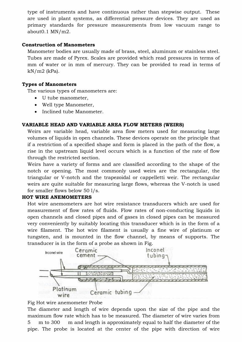
HOT WIRE ANEMOMETERS
Hot wire anemometers are hot wire resistance transducers which are used for
measurement of flow rates of fluids. Flow rates of non-conducting liquids in
open channels and closed pipes and of gases in closed pipes can be measured
very conveniently by suitably locating this transducer which is in the form of a
wire filament. The hot wire filament is usually a fine wire of platinum or
tungsten, and is mounted in the flow channel, by means of supports. The
transducer is in the form of a probe as shown in Fig.
Fig Hot wire anemometer Probe
The diameter and length of wire depends upon the size of the pipe and the
maximum flow rate which has to be measured. The diameter of wire varies from
5 m to 300 m and length is approximately equal to half the diameter of the
pipe. The probe is located at the center of the pipe with direction of wire

perpendicular to the direction of fluid flow.
The hot wire techniques of measuring flow velocities has assumed great
significance as the measurement can be done without disturbing the existing
conditions. The method can be used for measurement of low velocities. The hot
wire probe can be placed in small sized pipes without causing any pressure
drop in the fluid stream. However, it can measure only the average velocity of
flow. The method is unsuitable for velocity measurements if the fluid is
conducting liquid. The main applications of hot wire anemometers are for gas
flow and wind velocity measurements and in the laboratory for flow
measurements of non-conducting liquids and gases.
Hot wire anemometers are commonly used in two different modes i.e.
(i) Constant current type and
(ii) Constant temperature type.
MEASUREMENT OF LIQUID LEVEL
In industry, usually vast quantities of liquids such as water, solvents,
chemicals, etc. are used in a number of industrial processes. Liquid level
measurements are made to ascertain the quantity of liquid held in a container
or vessel. The liquid level affects both pressure and rate of flow in and out of the
container and therefore its measurement and / or control becomes quite
important in a variety of processes encountered in modern manufacturing
plants. Liquid level measurements can be broadly classified as:
1. Direct methods and
2. Indirect methods
CONTROL SYSTEMS
Introduction
The term control means to regulate, direct or command. A control system may
thus be defined as: "A grouping of devices and components connected or related
so as to command, direct or regulate itself or another system".
In general, the objectives of control system are to control or regulate the output
in some prescribed manner by the inputs through the elements of the control
system.
Automatic control is the maintenance of a desired value of quantity or condition
by measuring the existing value; compare it with the desired value and
employing the difference to initiate action for reducing this difference.
Automatic control systems are used in practically every field of our life. Since,
nowadays it has become a tendency to complete the required work or a task
automatically by reducing the physical and mental effort. The different
applications of automatic control systems are:
1. Domestically they are used in heating and air conditioning.
2. Industrial applications of automatic control system include:
(i) Automatic control of machine tool operations.
(ii) Automatic assembly lines.
(iii)Quality control, inventory control.
(iv) (iv)In process industries such as food, petroleum, chemical, steel, power
etc. for the control of temperature, pressure, flow etc.
(v) Transportation systems, robotics, power systems also uses automatic
control for their operation and control.
(vi) Compressors, pumps, refrigerators.
(vii) Automatic control systems are also used in space technology and
defence applications such as nuclear power weapons, guided missiles etc.
(viii) Even the control of social and economic systems may be approached
from theory of automatic control.
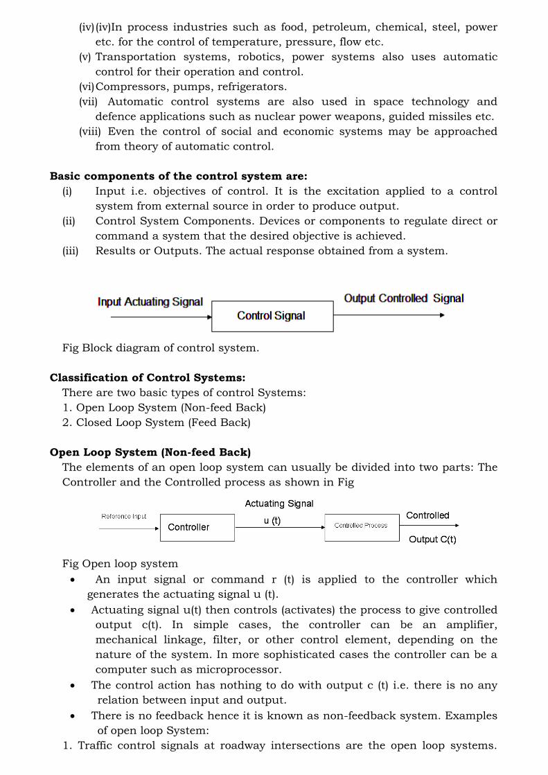
Basic components of the control system are:
(i) Input i.e. objectives of control. It is the excitation applied to a control
system from external source in order to produce output.
(ii) Control System Components. Devices or components to regulate direct or
command a system that the desired objective is achieved.
(iii) Results or Outputs. The actual response obtained from a system.
Fig Block diagram of control system.
Classification of Control Systems:
There are two basic types of control Systems:
1. Open Loop System (Non-feed Back)
2. Closed Loop System (Feed Back)
Open Loop System (Non-feed Back)
The elements of an open loop system can usually be divided into two parts: The
Controller and the Controlled process as shown in Fig
Fig Open loop system
• An input signal or command r (t) is applied to the controller which
generates the actuating signal u (t).
• Actuating signal u(t) then controls (activates) the process to give controlled
output c(t). In simple cases, the controller can be an amplifier,
mechanical linkage, filter, or other control element, depending on the
nature of the system. In more sophisticated cases the controller can be a
computer such as microprocessor.
• The control action has nothing to do with output c (t) i.e. there is no any
relation between input and output.
• There is no feedback hence it is known as non-feedback system. Examples
of open loop System:
1. Traffic control signals at roadway intersections are the open loop systems.
The glowing of red and green lamps represents the input. When the red lamp
grows the traffic stops. When green lamp glows, it directs the traffic to start.
The red and green light travels are predetermined by a calibrated timing
mechanism and are in no way influenced by the volume of traffic (output).
2. Automatic washing machine: In washing machine, input is dirty clothes,
water, soap and output is clean cloths. Soaking, washing and rinsing operations
are carried out on a time basis. However, the machine does not measure the
output signal, namely the cleanliness of the clothes.
Advantages of Open Loop System:
1. Simple in construction.
2. Economic.
3. More stable.
4. Easy maintenance.
Disadvantages of Open Loop System:
1. Inaccurate and unreliable.
2. It is affected by internal and external disturbances; the output may differ
from the desired value.
3. It needs frequent and careful calibrations for accurate results.
4. Open loop systems are slow because they are manually controlled.
5. There is no feedback control. The control systems are rather
unsophisticated.
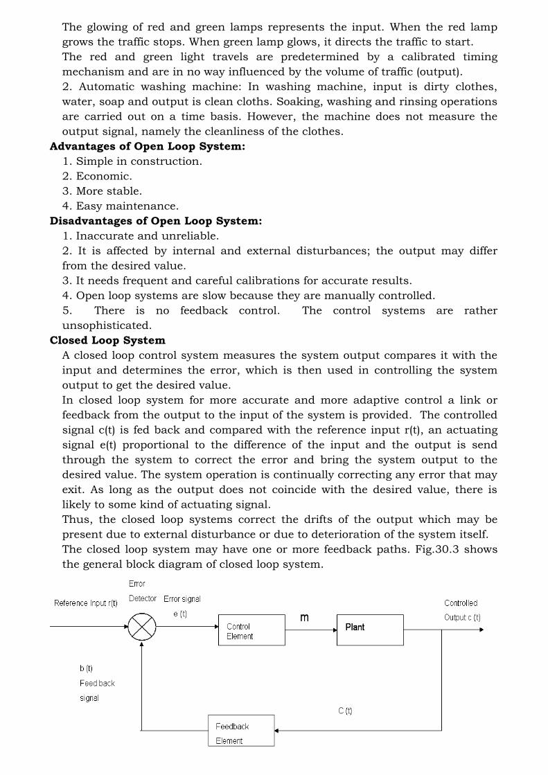
Closed Loop System
A closed loop control system measures the system output compares it with the
input and determines the error, which is then used in controlling the system
output to get the desired value.
In closed loop system for more accurate and more adaptive control a link or
feedback from the output to the input of the system is provided. The controlled
signal c(t) is fed back and compared with the reference input r(t), an actuating
signal e(t) proportional to the difference of the input and the output is send
through the system to correct the error and bring the system output to the
desired value. The system operation is continually correcting any error that may
exit. As long as the output does not coincide with the desired value, there is
likely to some kind of actuating signal.
Thus, the closed loop systems correct the drifts of the output which may be
present due to external disturbance or due to deterioration of the system itself.
The closed loop system may have one or more feedback paths. Fig.30.3 shows
the general block diagram of closed loop system.

Fig. 30.3 Closed loop system r(t) = reference input e(t) = error or actuating signal
b(t) = feedback signal m = manipulation
Advantages of Closed Loop System:
• These systems can be used in hazardous or remote areas, such as
chemical plants, fertilizer plants, areas with high nuclear radiations, and
places at very high or very low temperatures.
• Increased productivity
• Relief of human beings from hard physical work and economy in operating
cost.
• Improvement in the quality and quantity of the products.
• They are more reliable than human operators.
• A number of variables can be handled simultaneously by closed loop
control systems.
• In such systems, there is reduced effect of non-linearity’s and distortions.
• Closed loop systems can be adjusted to optimum control performance.
• Such system senses environmental changes, as well as internal
disturbances and accordingly modifies the error.
• Satisfactory response over a wide range of input frequencies.
Disadvantages of Closed Loop Control System:
• It is more complex and expensive.
• Installation and adjustment is intricate.
• Maintenance is difficult as it involves complicated electronics.
Moreover, trained persons are required for maintenance.
• Due to feedback, system tries to correct the error time to time.
• Tendency to over correct the error may cause oscillations without
bound in the system.
• It is less stable as compared to open loop system.
Table Comparison between open loop and closed loop systems
Open Loop System Closed Loop System
1 No feed back Feedback is present
2 No error detector Error detector is included
3 Simple in construction, easy to built Complex design, difficult to built
4 Disturbances occurring in the
process is not controllable
Disturbance do not affect the process,
they can be controlled automatically
5 It is more stable It is less stable
6 Economical Expensive
7 Less accuracy Accurate
8 Response is slow Response is fast
9 Examples: Two way traffic control, automatic toaster, coffee
maker, hand drier
Examples: Human being, automatic electric irons, automatic speed control
system, centrifugal watt governor etc.
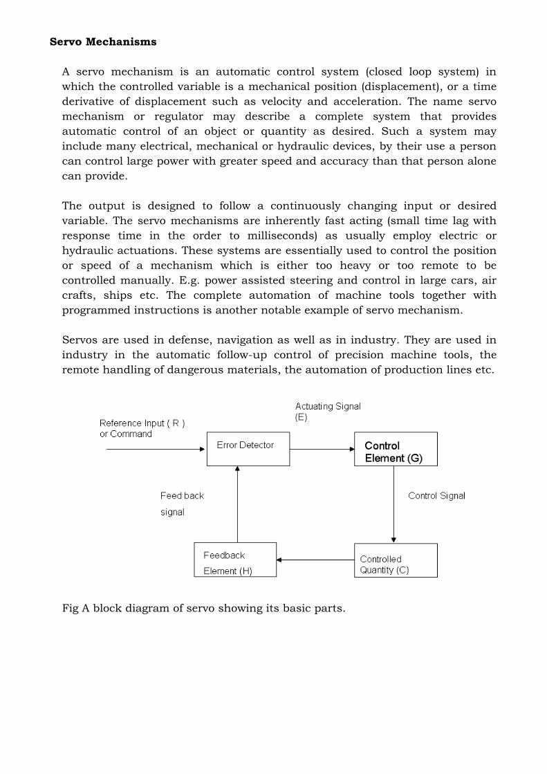
Servo Mechanisms
A servo mechanism is an automatic control system (closed loop system) in
which the controlled variable is a mechanical position (displacement), or a time
derivative of displacement such as velocity and acceleration. The name servo
mechanism or regulator may describe a complete system that provides
automatic control of an object or quantity as desired. Such a system may
include many electrical, mechanical or hydraulic devices, by their use a person
can control large power with greater speed and accuracy than that person alone
can provide.
The output is designed to follow a continuously changing input or desired
variable. The servo mechanisms are inherently fast acting (small time lag with
response time in the order to milliseconds) as usually employ electric or
hydraulic actuations. These systems are essentially used to control the position
or speed of a mechanism which is either too heavy or too remote to be
controlled manually. E.g. power assisted steering and control in large cars, air
crafts, ships etc. The complete automation of machine tools together with
programmed instructions is another notable example of servo mechanism.
Servos are used in defense, navigation as well as in industry. They are used in
industry in the automatic follow-up control of precision machine tools, the
remote handling of dangerous materials, the automation of production lines etc.
Fig A block diagram of servo showing its basic parts.
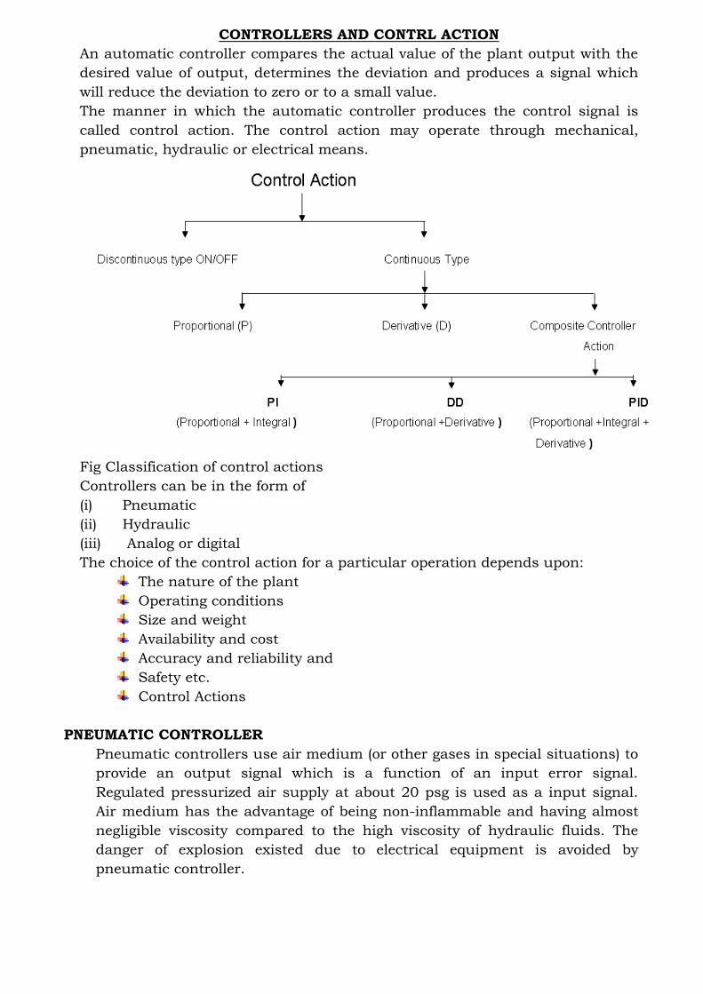
CONTROLLERS AND CONTRL ACTION
An automatic controller compares the actual value of the plant output with the
desired value of output, determines the deviation and produces a signal which
will reduce the deviation to zero or to a small value.
The manner in which the automatic controller produces the control signal is
called control action. The control action may operate through mechanical,
pneumatic, hydraulic or electrical means.
Fig Classification of control actions
Controllers can be in the form of
(i) Pneumatic
(ii) Hydraulic
(iii) Analog or digital
The choice of the control action for a particular operation depends upon:
The nature of the plant
Operating conditions
Size and weight
Availability and cost
Accuracy and reliability and
Safety etc.
Control Actions
PNEUMATIC CONTROLLER
Pneumatic controllers use air medium (or other gases in special situations) to
provide an output signal which is a function of an input error signal.
Regulated pressurized air supply at about 20 psg is used as a input signal.
Air medium has the advantage of being non-inflammable and having almost
negligible viscosity compared to the high viscosity of hydraulic fluids. The
danger of explosion existed due to electrical equipment is avoided by
pneumatic controller.
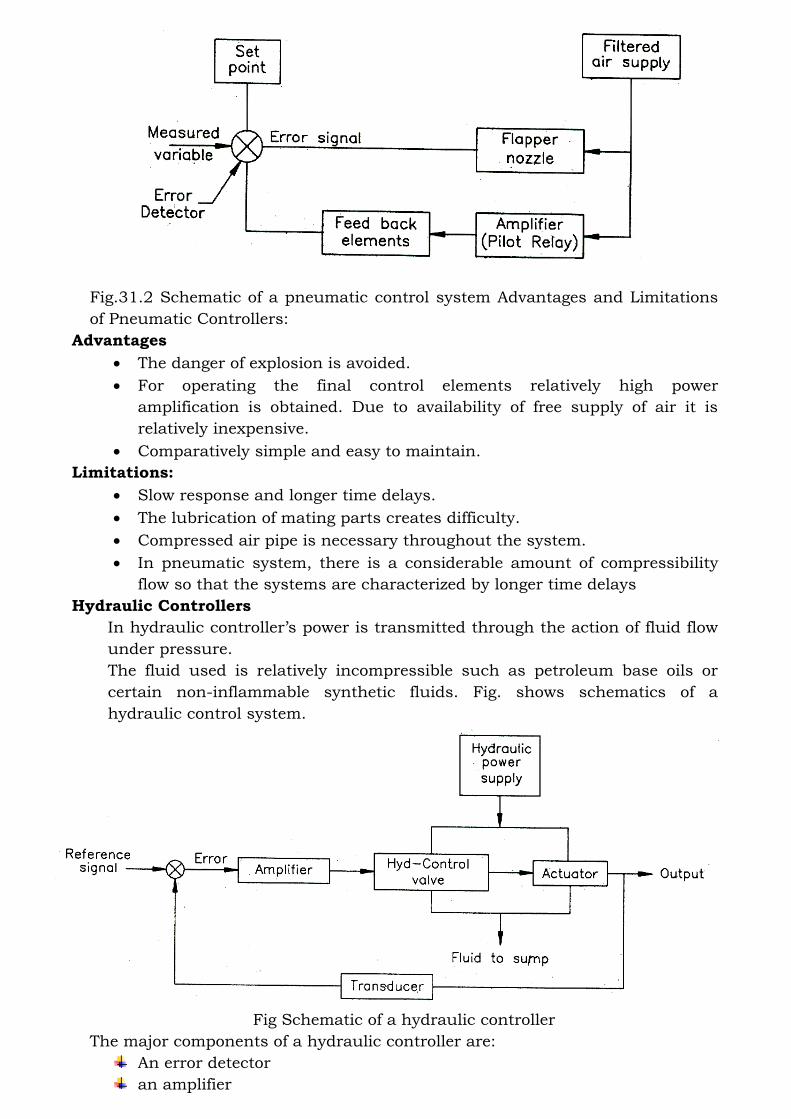
Fig.31.2 Schematic of a pneumatic control system Advantages and Limitations
of Pneumatic Controllers:
Advantages
• The danger of explosion is avoided.
• For operating the final control elements relatively high power
amplification is obtained. Due to availability of free supply of air it is
relatively inexpensive.
• Comparatively simple and easy to maintain.
Limitations:
• Slow response and longer time delays.
• The lubrication of mating parts creates difficulty.
• Compressed air pipe is necessary throughout the system.
• In pneumatic system, there is a considerable amount of compressibility
flow so that the systems are characterized by longer time delays
Hydraulic Controllers
In hydraulic controller’s power is transmitted through the action of fluid flow
under pressure.
The fluid used is relatively incompressible such as petroleum base oils or
certain non-inflammable synthetic fluids. Fig. shows schematics of a
hydraulic control system.
Fig Schematic of a hydraulic controller
The major components of a hydraulic controller are:
An error detector
an amplifier

A hydraulic control valve, and
An actuator.
Advantages of hydraulic controllers
High speed response.
High power gain.
Long life due to self-lubricating properties of fluid.
Simplicity of actuator system
Easy maintenance.
Limitations of hydraulic controllers
Hydraulic fluids require careful maintenance to remove impurities,
corrosive effects etc.
Seals should be properly maintained to prevent leakage of hydraulic
fluids.
Electric controllers
Electrical control devices are most widely used because of their accuracy and
fast response with easy handling techniques. Electric controller for
proportional, proportional plus integral and proportional + integral
+derivative actions may be divided into two types:
(1) The null balance type in which an electrical feedback signal is given to the
controller from the final elements
(2) The direct type in which there is no such feedback signal.
As with the pneumatic controller, the various control actions are accomplished
by modifying the feedback signal. This is done by adding properly combined
electrical resistances and capacitances to feedback circuit just as restrictions
and bellows were added in the pneumatic circuit.
A very simple form of two step controller is the room-temperature thermostat.
Fig.31.4 show simple type of electrical two position control. The U shaped
bimetal strip fixed at one end of the thermostat frame deflects when heated, its
free and moving in such a direction as to separate the fixed and moving
contacts. When the bimetal strip cools the two contacts are once more brought
in contact. The small permanent magnet ensures the opening and closing of the
contacts with a snap action to minimize the damage caused by arcing. The
adjusting screw varies the small range of temperature, sometimes called the
differential gap between contacts opening on rising temperature and closing on
falling temperature.
Fig Electrical two position control

DATA TRANSMISSION ELEMENTS
When the measured variables have to be transmitted over long distances from
the measuring points to a location for display or recording of data, data
transmission elements are employed. These are classified into two categories:
1. Land-line or cable type transmission elements.
2. Radio-frequency (RF) type data transmission elements.
In the former units, data is transmitted by wires or pipes while in the latter it is
transmitted by radio waves. The former finds applications in data transmission
in process plants power generating stations, etc. and includes electrical,
pneumatic and position type elements while the latter is used in aero-space
systems.
Electrical Type Data Transmission Elements
In these elements, the input measured variable, usually a motion signal is made
to change an electrical quantity, the effect of which is transmitted by wires to
the receiving end, for record or display. Figure 32.1 shows two such elements.
In Fig. 32.1(a), the position of contact C on a variable resistance AB is adjusted
by the input motion, changing the value of the current through the lines. The
current at the receiving end is a measure of the input variable. In this type,
resistance changes due to temperature changes introduce errors. In Fig.
32.1(b), instead of measuring the current at the receiving end a potentiometer is
used, which is balanced so that no current flows, as indicated by G. Thus, the
setting of the potentiometer gives an indication of the input signal. In this case,
the effect of change of line resistance due to temperature, etc. is eliminated.
Fig Data transmission by change of electric quantity
Pneumatic-Type Transmission Elements
These are also a land-line type. A typical arrangement is shown in Fig.
32.2, and uses the flapper-nozzle arrangement. The signal to be transmitted is
converted into the form of a motion signal x. With change in x, pressure P2
changes as shown. The pressure P2 gets transmitted to the receiving end and
May, by use of an elastic element, be converted to motion for recording.

Fig Pneumatic transmitter
Figure shows a flow transmitter of the pneumatic type, employing a system
similar to that of Fig the flow signal results in a pressure difference across the
restrictor (which may be an orifice or venture or a nozzle). The pressure
difference results in the deflection of an elastic diaphragm and the motion
signal is transmitted, by being converted to the pressure signal
Fig Pneumatic flow transmitter
Another type of pneumatic transmission system called force-balance type has
better linearity characteristics. The input signal is in the form of a force signal F
applied at the end of a pivoted lever (a motion input signal may be applied
through a spring, resulting in force F). Application of F rotates the level
clockwise as shown, decreasing the gap between the level extension and the
nozzle and thus increasing pressure P2 till the lever balances and no further
building up of pressure occurs. At balance,
Fig Force-balance type pneumatic transmitter

In pneumatic type transmitters, there is a pressure drop in transmission piping,
resulting in a reduction in the signal transmitted. In practice, these are used for
transmitting the signal over a few hundred meters.
Position-Type Data Transmission Elements
In these types, the motion signal (like rotation of a pointer) is transmitted over
long distances, by use of synchros. Two synchros - a transmitter and a receiver
are employed (Fig.32.5). A synchro consists of a stator with three coils at 120°,
inside which is a rotor, which is free to rotate within the stator windings. The
transmitting synchro is energized by an AC power source. If the two rotors are
in identical positions, the voltages in stators have the same magnitude but
opposite sense and no current flows in the stator wires. If the input rotor is
turned, making the two rotor positions different, current flows in the stator
wires producing a resulting torque which would align the two rotors making.
Thus, the angular motion i is transmitted to the receiving end.
Fig Synchro’s for data transmission
Radio-Frequency (RF) Transmission System
Such data transmission systems use radio-frequency waves for data
transmission and no wires or cables are needed between the transmitting and
receiving ends. In large systems like aero-space systems, a number of input
signals like temperature, pressure, vibrations, etc. may be transmitted by such
units.