Instrument Development Inquiry (Sixth Edition) · development. It may be stated that there is a...
262
Instrument Development Inquiry (Sixth Edition) by J.P. van der Meulen Netherlands WORLD METEOROLOGICAL ORGANIZATION INSTRUMENTS AND OBSERVING METHODS R E P O R T No. 71 WMO/TD No. 878 1998
Transcript of Instrument Development Inquiry (Sixth Edition) · development. It may be stated that there is a...

Instrument Development Inquiry
(Sixth Edition)
by
J.P. van der Meulen
Netherlands
W O R L D M E T E O R O L O G I C A L O R G A N I Z A T I O N
INSTRUMENTS AND OBSERVING METHODS
R E P O R T No. 71
WMO/TD No. 878
1998

NOTE
The designations employed and the presentation of material in this publication do not imply the expression ofany opinion whatsoever on the part of the Secretariat of the World Meteorological Organization concerning
the legal status of any country, territory, city or area, or its authorities, or concerning the limitation of thefrontiers or boundaries.
This report has been produced without editorial revision by the Secretariat. It is not an official WMOpublication and its distribution in this form does not imply endorsement by the Organization of the ideas
expressed

FOREWORD
The provision of compatible measurements of high quality is fundamental for the operationaland research programmes of Members of the World Meteorological Organization. Therefore, thedevelopment and use of new technology for effective and economical acquisition of data and, inparticular, for the automation of observations is considered to be of great importance. The TwelfthCongress of WMO urged that Members continue and, to the extent possible, increase their programmesfor the development of new data acquisition systems, sensors and instruments, including those formonitoring the composition of the atmosphere. This is often now done in close collaboration withinstrument manufacturers and designers in the private sector.
WMO, and particularly the Commission for Instruments and Methods of Observation (CIMO),has for a long time been publishing information 0fl new developments in instrumentation and dataacquisition systems. Since 1968 five editions of publication with the title of "Instruments Developmentlnquiry" have been published. This, the sixth edition of the Instrument Development Inquiry, containsthe information from a comprehensive survey of the state-of-the-art in development of meteorologicalinstruments and of the new Instruments introduced into service during the last four years. Theinformation was provided by 27 Members in 208 completed questionnaires. This demonstrates asignificantly growing interest and participation compared with the fifth edition.
The information in this publication will assist Members in selecting equipment for use in newapplications or as replacement for obsolete instrumentation. Availability of this publication toinstrument manufacturers may also be useful in decisions regarding development programmes.
I wish to thank Dr. J.P. van d& Meulen, the CIMO Rapporteur on Instrument Development,who has again prepared this excellent report and the Royal Netherlands Meteorological Institute for itssupport of this undertaking. My thanks go also to all those who contributed the information by means ofthe completed questionnaires.
(Dr. J. Kruus)President of the Commission for
Instruments and Methods of Observation

iv

Contents
0. Summary . . . . . . . . . . . . . . . . . . . . . . . . . . . . . . . . . . . . . . . . . . . . . . . . . . . . . . . . . . . . . . . . . . . . . . . . . . 1
1. Introduction . . . . . . . . . . . . . . . . . . . . . . . . . . . . . . . . . . . . . . . . . . . . . . . . . . . . . . . . . . . . . . . . . . . . . . . . 31. Background . . . . . . . . . . . . . . . . . . . . . . . . . . . . . . . . . . . . . . . . . . . . . . . . . . . . . . . . . . . . . . . . . . . . . 32. Organization . . . . . . . . . . . . . . . . . . . . . . . . . . . . . . . . . . . . . . . . . . . . . . . . . . . . . . . . . . . . . . . . . . . . . 33. Response . . . . . . . . . . . . . . . . . . . . . . . . . . . . . . . . . . . . . . . . . . . . . . . . . . . . . . . . . . . . . . . . . . . . . . . . 44. Items for classification . . . . . . . . . . . . . . . . . . . . . . . . . . . . . . . . . . . . . . . . . . . . . . . . . . . . . . . . . . . . . 55. Motivation . . . . . . . . . . . . . . . . . . . . . . . . . . . . . . . . . . . . . . . . . . . . . . . . . . . . . . . . . . . . . . . . . . . . . . 6
2. Analysis . . . . . . . . . . . . . . . . . . . . . . . . . . . . . . . . . . . . . . . . . . . . . . . . . . . . . . . . . . . . . . . . . . . . . . . . . . . 71. Introduction . . . . . . . . . . . . . . . . . . . . . . . . . . . . . . . . . . . . . . . . . . . . . . . . . . . . . . . . . . . . . . . . . . . . . 72. Results . . . . . . . . . . . . . . . . . . . . . . . . . . . . . . . . . . . . . . . . . . . . . . . . . . . . . . . . . . . . . . . . . . . . . . . . . 73. General conclusions . . . . . . . . . . . . . . . . . . . . . . . . . . . . . . . . . . . . . . . . . . . . . . . . . . . . . . . . . . . . . . . 12
3. Information per entry in detail . . . . . . . . . . . . . . . . . . . . . . . . . . . . . . . . . . . . . . . . . . . . . . . . . . . . . . . . . . 131. Instruments under development . . . . . . . . . . . . . . . . . . . . . . . . . . . . . . . . . . . . . . . . . . . . . . . . . . . . . . 14
1.1. Measurement of Meteorological Variables . . . . . . . . . . . . . . . . . . . . . . . . . . . . . . . . . . . . 141.1.1. General . . . . . . . . . . . . . . . . . . . . . . . . . . . . . . . . . . . . . . . . . . . . . . . . . . . . . . . . . . . . . . 141.1.2. Measurement of temperature . . . . . . . . . . . . . . . . . . . . . . . . . . . . . . . . . . . . . . . . . . . . . 141.1.3. Measurement of atmospheric pressure . . . . . . . . . . . . . . . . . . . . . . . . . . . . . . . . . . . . . . 241.1.4. Measurement of humidity . . . . . . . . . . . . . . . . . . . . . . . . . . . . . . . . . . . . . . . . . . . . . . . . 271.1.5. Measurement of surface wind . . . . . . . . . . . . . . . . . . . . . . . . . . . . . . . . . . . . . . . . . . . . . 321.1.6. Measurement of precipitation . . . . . . . . . . . . . . . . . . . . . . . . . . . . . . . . . . . . . . . . . . . . . 441.1.7. Measurement of radiation . . . . . . . . . . . . . . . . . . . . . . . . . . . . . . . . . . . . . . . . . . . . . . . . 481.1.8. Measurement of sunshine duration . . . . . . . . . . . . . . . . . . . . . . . . . . . . . . . . . . . . . . . . . 571.1.9. Measurement of visibility . . . . . . . . . . . . . . . . . . . . . . . . . . . . . . . . . . . . . . . . . . . . . . . . 581.1.10. Measurement of evaporation . . . . . . . . . . . . . . . . . . . . . . . . . . . . . . . . . . . . . . . . . . . . . 591.1.11. Measurement of soil moisture . . . . . . . . . . . . . . . . . . . . . . . . . . . . . . . . . . . . . . . . . . . . 601.1.12. Measurement of upper air pressure, temperature, humidity . . . . . . . . . . . . . . . . . . . . . 611.1.13. Measurement of upper wind . . . . . . . . . . . . . . . . . . . . . . . . . . . . . . . . . . . . . . . . . . . . . 651.1.14. present and past weather, state of the ground: . . . . . . . . . . . . . . . . . . . . . . . . . . . . . . . 661.1.15. Observation of clouds . . . . . . . . . . . . . . . . . . . . . . . . . . . . . . . . . . . . . . . . . . . . . . . . . . 681.2. Observing Systems . . . . . . . . . . . . . . . . . . . . . . . . . . . . . . . . . . . . . . . . . . . . . . . . . . . . . . . 701.2.1. Measurement at automatic meteorological stations . . . . . . . . . . . . . . . . . . . . . . . . . . . . 701.2.2. Instruments and observations at aeronautical stations . . . . . . . . . . . . . . . . . . . . . . . . . . 741.2.3. Aircraft observations . . . . . . . . . . . . . . . . . . . . . . . . . . . . . . . . . . . . . . . . . . . . . . . . . . . . 751.2.4. Marine observations . . . . . . . . . . . . . . . . . . . . . . . . . . . . . . . . . . . . . . . . . . . . . . . . . . . . 771.2.5. Special profiling techniques for the boundary layer and the troposphere . . . . . . . . . . . . 791.2.6. Rocket measurements in the stratosphere and mesosphere . . . . . . . . . . . . . . . . . . . . . . . 801.2.7. Locating the sources of atmospherics . . . . . . . . . . . . . . . . . . . . . . . . . . . . . . . . . . . . . . . 801.3. Other . . . . . . . . . . . . . . . . . . . . . . . . . . . . . . . . . . . . . . . . . . . . . . . . . . . . . . . . . . . . . . . . . 81
2. Instruments put into operational use . . . . . . . . . . . . . . . . . . . . . . . . . . . . . . . . . . . . . . . . . . . . . . . . . . . 872.1. Measurement of Meteorological Variables . . . . . . . . . . . . . . . . . . . . . . . . . . . . . . . . . . . . 872.1.1. General . . . . . . . . . . . . . . . . . . . . . . . . . . . . . . . . . . . . . . . . . . . . . . . . . . . . . . . . . . . . . . 872.1.2. Measurement of temperature . . . . . . . . . . . . . . . . . . . . . . . . . . . . . . . . . . . . . . . . . . . . . 902.1.3. Measurement of atmospheric pressure . . . . . . . . . . . . . . . . . . . . . . . . . . . . . . . . . . . . . 1232.1.4. Measurement of humidity . . . . . . . . . . . . . . . . . . . . . . . . . . . . . . . . . . . . . . . . . . . . . . . 1282.1.5. Measurement of surface wind . . . . . . . . . . . . . . . . . . . . . . . . . . . . . . . . . . . . . . . . . . . . 1292.1.6. Measurement of precipitation . . . . . . . . . . . . . . . . . . . . . . . . . . . . . . . . . . . . . . . . . . . . 146
v
2.1.7. Measurement of radiation . . . . . . . . . . . . . . . . . . . . . . . . . . . . . . . . . . . . . . . . . . . . . . . 1572.1.8. Measurement of sunshine duration . . . . . . . . . . . . . . . . . . . . . . . . . . . . . . . . . . . . . . . . 1682.1.9. Measurement of visibility . . . . . . . . . . . . . . . . . . . . . . . . . . . . . . . . . . . . . . . . . . . . . . . 1692.1.10. Measurement evaporation . . . . . . . . . . . . . . . . . . . . . . . . . . . . . . . . . . . . . . . . . . . . . . 1802.1.11. Measurement of soil moisture . . . . . . . . . . . . . . . . . . . . . . . . . . . . . . . . . . . . . . . . . . . 1812.1.12. Measurement of upper air pressure, temperature, humidity . . . . . . . . . . . . . . . . . . . . 1812.1.13. upper wind . . . . . . . . . . . . . . . . . . . . . . . . . . . . . . . . . . . . . . . . . . . . . . . . . . . . . . . . . 1882.1.14. present and past weather, state of the ground . . . . . . . . . . . . . . . . . . . . . . . . . . . . . . . 1932.1.15. Observation of clouds . . . . . . . . . . . . . . . . . . . . . . . . . . . . . . . . . . . . . . . . . . . . . . . . . 1952.2. Observing Systems . . . . . . . . . . . . . . . . . . . . . . . . . . . . . . . . . . . . . . . . . . . . . . . . . . . . . . 2022.2.1. Measurement at automatic meteorological stationss . . . . . . . . . . . . . . . . . . . . . . . . . . . 2022.2.2. Instruments and observations at aeronautical stations . . . . . . . . . . . . . . . . . . . . . . . . . 2242.2.3. Aircraft observations . . . . . . . . . . . . . . . . . . . . . . . . . . . . . . . . . . . . . . . . . . . . . . . . . . . 2272.2.4. Marine observations . . . . . . . . . . . . . . . . . . . . . . . . . . . . . . . . . . . . . . . . . . . . . . . . . . . 2292.2.5. Special profiling techniques for the boundary layer and the troposphere . . . . . . . . . . . 2322.2.6. Rocket measurements in the stratosphere and mesosphere . . . . . . . . . . . . . . . . . . . . . . 2362.2.7. Locating the sources of atmospherics . . . . . . . . . . . . . . . . . . . . . . . . . . . . . . . . . . . . . . 2362.3. Other . . . . . . . . . . . . . . . . . . . . . . . . . . . . . . . . . . . . . . . . . . . . . . . . . . . . . . . . . . . . . . . . 237
Appendix A: Questionnaire . . . . . . . . . . . . . . . . . . . . . . . . . . . . . . . . . . . . . . . . . . . . . . . . . . . . . . . . . . . . . . 247
vi

0. Summary
This publication reports on the results of the sixth edition of the Instrument Development Inquiry. TheCIMO Working Group on Surface Measurements had decided to circulate to all W.M.O. Members a newquestionnaire on instrument development. This inquiry is in line with resolution 4 (Cg-XII) and CIMO-XIrecommendations. A total number 208 completed questionnaires from 27 countries were returned. Responsesfrom 15 countries informing that no developments were carried out were recieved as well. In this questionnairea choice could be made between:
(1) Instrument under development, and(2) Instrument put into operational use in recent 4 years
The questionnaire also asked to indicate the category-of-measurement number to which the (to be) developedinstrument belongs. Twenty-three possibilities were put on the List of Categories (like Measurement ofatmospheric pressure, or temperature, etc.). This list is based on the newest, sixth version of the Guide toMeteorological Instruments and Methods of Observation (WMO No. 8), but it was decided to exclude ten typesof measurements or techniques. The reason for this was to eliminate overlap with other work by WMO on thismatter. The categories which were left outside the scope of the questionnaire are:
1.16 Measurement of Ozone1.17 Measurement of atmospheric composition, toxic chemicals and radioactive substances.2.8 Satellite observations2.9 Radar measurements2.10 Balloon techniques3.1 Sampling meteorological variables3.2 Data reduction3.3 Quality management3.4 Training of instrument specialists3.5 Testing, calibration and intercomparisons
Nevertheless, a category,
3. Other
was included for al other possible technologies, which may be outside the scoope of the CIMO guide.
The questionnaire included for the first time a request for background information on the motives of thedevelopment. It may be stated that there is a significant trend in the policy to do future instrument development:the impact of this activity in any long term plan will depend on the principle motives behind the need of furtherdevelopment.
It should be noted that there was a strong increase in the number of replies: 208 replies for this editionimplies an increase of 45% with respect to the previous edition of the Instrument Development Inquiry (FifthEdition, Instruments and Observing Methods Report No. 54, 1993, WMO/TD - No. 578). Obviously there still isan increasing need to develop new meteorological measuring and data-acquisition devices.
In this report, after a short introduction, a number of figures and tables are presented which are a result ofthe analysis of the entries. In the last two chapters the replies are presented, divided into instruments underdevelopment and instrument put into operational use. Finally, the questionnaire itself is attached to this report asan appendix.
1

2

1. Introduction
1. Background
The World Meteorological Organization has recognized the challenge of scientific and technologicaladvances as a major influence of the World Weather Watch Programme. Consequently, the Instruments andMethods of Observation Programme (IMOP), an important component of the Fourth WMO Long-Term Plan(FLTP), concerns itself with a number of specific objectives on this matter. This importance was one of thereasons for the Twelth World Meteorological Congress to adopt resolution 4 (Cg-XII) on the IMOP. Inparticular, project 16.1 of the FLTP, published in WMO-No. 830, Part II, Volume 1, includes the specific tasksin line with the main long-term objectives of the IMOP. It is stated in the FLTP that the W.M.O. Commissionfor Instruments and Methods of Observation (CIMO) will play a leading role in the realization of the IMOPprogramme.
In line of these objectives CIMO-XI appointed a Rapporteur (the author of this report), to serve within theWorking Group on Surface Measurements as a focal point on the matter of Instrument Development. Based onthe positive experiences of the previous inquiries the Working Group decided to organize a new inquiry.
2. Organization
In July 1997 a request to complete the questionnaire was distributed to all W.M.O. Members to be returnedbefore 15 August 1997 (see Appendix A for a copy of this questionnaire). Most of the replies were received bythe rapporteur before September 1997, but the latest reply was received in Februari 1998. Therefore the state-of-development for all instruments under development, indicated in the questionnaire may be dated as 1 September1997.
All replies were entered into an database on an IBM-compatible PC. The data entries were selected, sortedand presented in Chapter 3 of this report. In Chapter 3, paragraph 1, all replies concerning instruments underdevelopment are presented, whereas in paragraph 2 of that Chapter the replies on instruments put intooperational use are presented. For each of both classes, the replies are sorted out over 23 categories.
The questionnaire contained a number of questions concerning principle of operation and technology, themain technical characteristics, experiences and financial aspects. An overview of these questions is given below:
General information requests:1. Short identification of the instrument including the parameter measured, or its function2. State of development, or first year of operational use3. Principle of operation4. Main technical characteristics:
4.1 application4.2 measuring range4.3 uncertainty4.4 time constant4.5 averaging time4.6 reliability4.7 interface and output details4.8 power requirements4.9 servicing interval4.10 other characteristics
Experiences and other information:5. Experience from comparisons and tests performed
3
6. Costs, preferably in US$. For instruments under development, please enter estimated costs,6.1 unit cost at factory6.2 annual operating costs
7. Name and address of person responsible for further information (Name, Address, Telephone, Telefax,e_mail address, URL or Internet WEB site)
8. Major bibliographic references, applicable patents, etc.
Because the replies are entered into a database, it is possible to obtain easily these data as a computer file.Members who are interested to obtain such a file are kindly invited to contact the author of this report:
dr Jitze P. van der Meulen,Royal Netherlands Meteorological InstituteOperational Observations,Postbus 2013730 AE De Bilt, Netherlands.tel.: +31 30 2206432fax : +31 30 2210407e-mail: [email protected] (internet)
The most convenient format will be in WordPerfect 5.1 "Mailmerge secondary source" on a MS-DOS formatteddiskette (or via e_mail), but other formats are also available.
3. Response
In Chapter 3, results of statistical analysis are presented: Number of entries per country, per category,classification of the status, i.e. under development or put into operational use, and classification of motives.
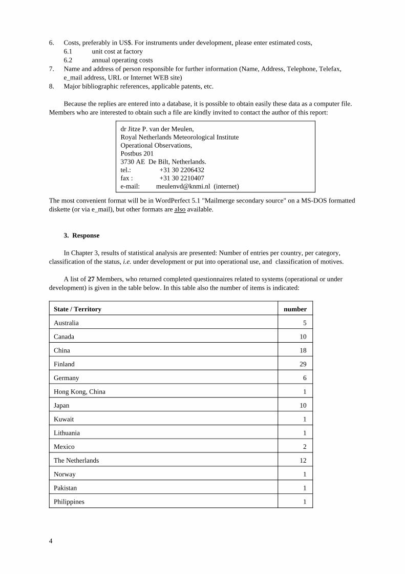
A list of 27 Members, who returned completed questionnaires related to systems (operational or underdevelopment) is given in the table below. In this table also the number of items is indicated:
State / Territory number
Australia 5
Canada 10
China 18
Finland 29
Germany 6
Hong Kong, China 1
Japan 10
Kuwait 1
Lithuania 1
Mexico 2
The Netherlands 12
Norway 1
Pakistan 1
Philippines 1
4
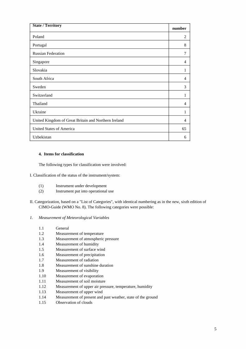
State / Territorynumber
Poland 2
Portugal 8
Russian Federation 7
Singapore 4
Slovakia 1
South Africa 4
Sweden 3
Switzerland 1
Thailand 4
Ukraine 1
United Kingdom of Great Britain and Northern Ireland 4
United States of America 65
Uzbekistan 6
4. Items for classification
The following types for classification were involved:
I. Classification of the status of the instrument/system:
(1) Instrument under development(2) Instrument put into operational use
II. Categorization, based on a "List of Categories", with identical numbering as in the new, sixth edition ofCIMO-Guide (WMO No. 8). The following categories were possible:
1. Measurement of Meteorological Variables
1.1 General1.2 Measurement of temperature1.3 Measurement of atmospheric pressure1.4 Measurement of humidity1.5 Measurement of surface wind1.6 Measurement of precipitation1.7 Measurement of radiation1.8 Measurement of sunshine duration1.9 Measurement of visibility1.10 Measurement of evaporation1.11 Measurement of soil moisture1.12 Measurement of upper air pressure, temperature, humidity1.13 Measurement of upper wind1.14 Measurement of present and past weather, state of the ground1.15 Observation of clouds
5

2. Observing Systems
2.1 Measurement at automatic meteorological stations2.2 Instruments and observations at aeronautical stations2.3 Aircraft observations2.4 Marine observations2.5 Special profiling techniques for the boundary layer and the troposphere2.6 Rocket measurements in the stratosphere and mesosphere2.7 Locating the sources of atmospherics
3.0 Other
To eliminate overlap with work to be done by other CIMO rapporteurs or working groups it was decided afterconsultion with the President of CIMO to focus on surface measurements only. As a consquency the followingitems where left outside the questionnaire: 1.16 Measurement of Ozone, 1.17 Measurement of atmosphericcomposition, toxic chemicals and radioactive substances, 2.8 Satellite observations, 2.9 Radar measurementsand 2.10 Balloon techniques. Other items which are not typically indicated in the list are: Road weather, icing,measurement of the freezing point and measurements typically useful for numerical weather prediction (NWP).All these items can be found under category 3, Other.
5. Motivation
With regards to the previous inquiry a new question was added concerning the motives behind theinstrument development, to be considered as background information. The following motives were suggestedbeforehand:
(1) Cost effectiveness (initial or operational)(2) Automation of manual observation(3) New type of observation(4) Improved reliability or accuracy(5) Less maintenance(6) Improved quality control(7) Data reduction
In Chapter 2 results are presented concerning this question. Moreover a relatively large number of alternativemotives are given in that Chapter.
6
2. Analysis
1. Introduction
In part one of the questionnaire, "A. Classification" (see App. A for details), it was requested to indicate 1)the status of the development (under development or recently put into operational use), 2) the category numberand 3) the motive of the development. Off course also the name of the country has to be indicated. As a result itis possible to perform statistics concerning these items. Results of this statistical analysis will inform about thecurrent trend in instrument development and its motives. In this Chapter the results of these statistics will bepresented as figures. Moreover typical categories and motives, as well as popular technologies and mayorconclusions are presented at the end of this Chapter. The detailed replies from the questionnaire are placed inChapter 3.
2. Results
2.1. Number of entries per State/Territory
From 27 Members a total amount of 208 completed questionnaires were received. In fig. 1 an overview ofthese countries is presented together with there amount of entries. In this figure an indication is given of thestatus of the development (operational/under development, see next par.)
2.2. Classification of the entries
The total amount of the 208 entries can be divided over two types of classes: "Under development" and"Operational":
(1) Instrument under development . . . . . . . . . . . . . . . . . . . . . . . . . . . . . . . . . . . . . . . . . . . . . . . . . . . . . . 67(2) Instrument put in operational use in recent 4 years . . . . . . . . . . . . . . . . . . . . . . . . . . . . . . . . . . . . . 141
For a number of entries in class (1) it was indicated that the instrument was still under development but that anearlier type was put into operational in the recent 4 years. On the other hand, for some entries of class (2) it wasindicated that the instrument was put into operational use but that developments were still going on. Forconvenience a so-called pie slice diagram is presented in fig. 2. Obviously the number of instruments put intooperational use is much larger the instruments under development (68% versus 32%).
7
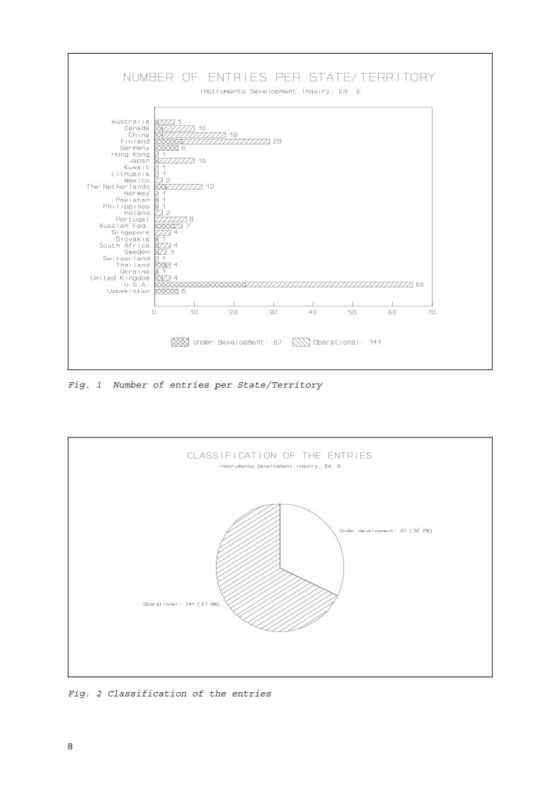
Fig. 1 Number of entries per State/Territory
Fig. 2 Classification of the entries
8

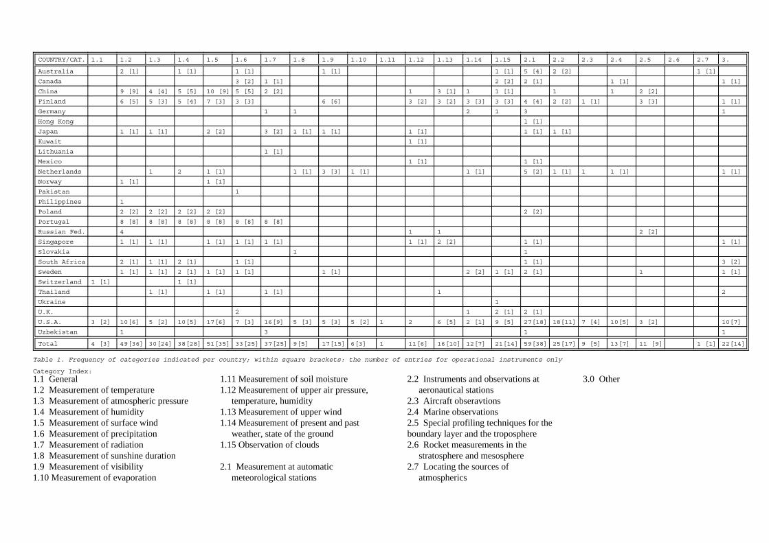
2.3. Number of entries per category
In the questionnaire space was left to indicate more than one category from the List of Categories.Therefore each entry will refer to one or more than one category. As a consequence the total amount ofcategories referred to from the whole set of completed questionnaires is much larger than 143. In table 1 amatrix is presented indicating the total number of entries per category and per country. The number in squarebrackets represents the amount of instruments of the total number of instruments for this category which wereput into operational use recently, i.e.:
"total number" ["number of operational instruments"]
In fig. 3 a general overview is given for the distribution of all entries over the categories:
Fig. 3 Number of entries per category
Categories, indicated under "3. Other" were typical "Icing" and "Freezing point measurements". From thisdiagram it is clearly demonstrated that the development of automatic stations (Synoptical, climatological oraeronautical) is the most popular item (cat. 2.1). Other categories which are currently in the picture are the wellknown classical categories like 1.5 Measurement of surface wind and 1.2 Measurement of temperature.
9
COUNTRY/CAT. 1.1 1.2 1.3 1.4 1.5 1.6 1.7 1.8 1.9 1.10 1.11 1.12 1.13 1.14 1.15 2.1 2.2 2.3 2.4 2.5 2.6 2.7 3.
Australia 2 [1] 1 [1] 1 [1] 1 [1] 1 [1] 5 [4] 2 [2] 1 [1]
Canada 3 [2] 1 [1] 2 [2] 2 [1] 1 [1] 1 [1]
China 9 [9] 4 [4] 5 [5] 10 [9] 5 [5] 2 [2] 1 3 [1] 1 1 [1] 1 1 2 [2]
Finland 6 [5] 5 [3] 5 [4] 7 [3] 3 [3] 6 [6] 3 [2] 3 [2] 3 [3] 3 [3] 4 [4] 2 [2] 1 [1] 3 [3] 1 [1]
Germany 1 1 2 1 3 1
Hong Kong 1 [1]
Japan 1 [1] 1 [1] 2 [2] 3 [2] 1 [1] 1 [1] 1 [1] 1 [1] 1 [1]
Kuwait 1 [1]
Lithuania 1 [1]
Mexico 1 [1] 1 [1]
Netherlands 1 2 1 [1] 1 [1] 3 [3] 1 [1] 1 [1] 5 [2] 1 [1] 1 1 [1] 1 [1]
Norway 1 [1] 1 [1]
Pakistan 1
Philippines 1
Poland 2 [2] 2 [2] 2 [2] 2 [2] 2 [2]
Portugal 8 [8] 8 [8] 8 [8] 8 [8] 8 [8] 8 [8]
Russian Fed. 4 1 1 2 [2]
Singapore 1 [1] 1 [1] 1 [1] 1 [1] 1 [1] 1 [1] 2 [2] 1 [1] 1 [1]
Slovakia 1 1
South Africa 2 [1] 1 [1] 2 [1] 1 [1] 1 [1] 3 [2]
Sweden 1 [1] 1 [1] 2 [1] 1 [1] 1 [1] 1 [1] 2 [2] 1 [1] 2 [1] 1 1 [1]
Switzerland 1 [1] 1 [1]
Thailand 1 [1] 1 [1] 1 [1] 1 2
Ukraine 1
U.K. 2 1 2 [1] 2 [1]
U.S.A. 3 [2] 10[6] 5 [2] 10[5] 17[6] 7 [3] 16[9] 5 [3] 5 [3] 5 [2] 1 2 6 [5] 2 [1] 9 [5] 27[18] 18[11] 7 [4] 10[5] 3 [2] 10[7]
Uzbekistan 1 3 1 1
Total 4 [3] 49[36] 30[24] 38[28] 51[35] 33[25] 37[25] 9[5] 17[15] 6[3] 1 11[6] 16[10] 12[7] 21[14] 59[38] 25[17] 9 [5] 13[7] 11 [9] 1 [1] 22[14]
Table 1. Frequency of categories indicated per country; within square brackets: the number of entries for operational instruments only
Category Index:
1.1 General1.2 Measurement of temperature1.3 Measurement of atmospheric pressure1.4 Measurement of humidity1.5 Measurement of surface wind1.6 Measurement of precipitation1.7 Measurement of radiation1.8 Measurement of sunshine duration1.9 Measurement of visibility1.10 Measurement of evaporation
1.11 Measurement of soil moisture1.12 Measurement of upper air pressure,
temperature, humidity1.13 Measurement of upper wind1.14 Measurement of present and past
weather, state of the ground1.15 Observation of clouds
2.1 Measurement at automaticmeteorological stations
2.2 Instruments and observations ataeronautical stations
2.3 Aircraft obseravtions2.4 Marine observations2.5 Special profiling techniques for theboundary layer and the troposphere2.6 Rocket measurements in the
stratosphere and mesosphere2.7 Locating the sources of
atmospherics
3.0 Other
In the questionnaire it was not requested to classify the typical technologies use by the instruments.Nevertheless it was possible to identify from the more detailed questions of part B of the questionnaire thatespecially optical technologies are still (like with the previous inquiry) runners up: Optical techniques areinvolved in the measurements of radiation, cloud observations, present weather observations, humidity,precipitation, visibility, sunshine duration. Optical technolies are especially used in instruments to automizevisual observations. On the other hand it must be noted that the use of microprocessors (insidesensors/transmitter, or inside datalogging systems) is now a widespread phenomenon.
2.4. Motivation aspect
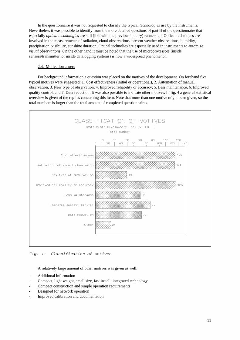
For background information a question was placed on the motives of the development. On forehand fivetypical motives were suggested: 1. Cost effectiveness (initial or operational), 2. Automation of manualobservation, 3. New type of observation, 4. Improved reliability or accuracy, 5. Less maintenance, 6. Improvedquality control, and 7. Data reduction. It was also possible to indicate other motives. In fig. 4 a general statisticaloverview is given of the replies concerning this item. Note that more than one motive might been given, so thetotal numbers is larger than the total amount of completed questionnaires.
A relatively large amount of other motives was given as well:
Fig. 4. Classification of motives
- Additional information- Compact, light weight, small size, fast install, integrated technology- Compact construction and simple operation requirements- Designed for network operation- Improved calibration and documentation
11

- Improved cosine response- Improved response time- Improved/more efficient presentation of data- More efficiency- PC or Mac-based, low cost- possibility of measurement points dispersion in vast areas- Scalable architecture suitable for large networks- Suitability for aircraft use (Model TSP-700A)- Technology upgrade- Technology upgrade- Thermal stabilization- To make up for lack of personnel. Real time information.- Updating radiosonde network- use for magnetometer for north reference- very wide measurement range- Wind shear/microburst prediction
Clearly two typical arguments are the basic motives for instrument development:
(1) Cost effectiveness(2) Automation of manual observation,(4) Improved reliability or accuracy.
It should be noticed that the following motive is less popular:
(3) New type of observation,
which implies that there is only minor interest in the meteorological community to discover new types ofobservation, which might be useful for meteorological or climatological purposes.
3. General conclusions
Based on the previous mentioned results the following conclusions may be drawn:
- A very large number of completed questionnaires were returned, 45% more than for the previous inquiry,- Cost effectiveness, Automation of Manual Observation, and Improved Reliability or Accuracy are the most
important motives for initiating any instrument development.- The most popular categories for which instruments or systems are developed are the categories concerning
automatic data acquisition, processing and transmission: Automatic Weather Stations. Notice that thedevelopment for such systems is focused merely on interfacing of received information by usingmicroprocessors than on sensor technology.
- An important recognized technology used in new developed instruments is optics. Many developed sensorsfrom many categories are based on optical techniques.
- Typical measurements outside the scoop not put into the list of categories: Icing, and Freezing PointMeasurements.
- Especially "road weather" meteorology is mentioned as an application.
12
3. Information per entry in detail
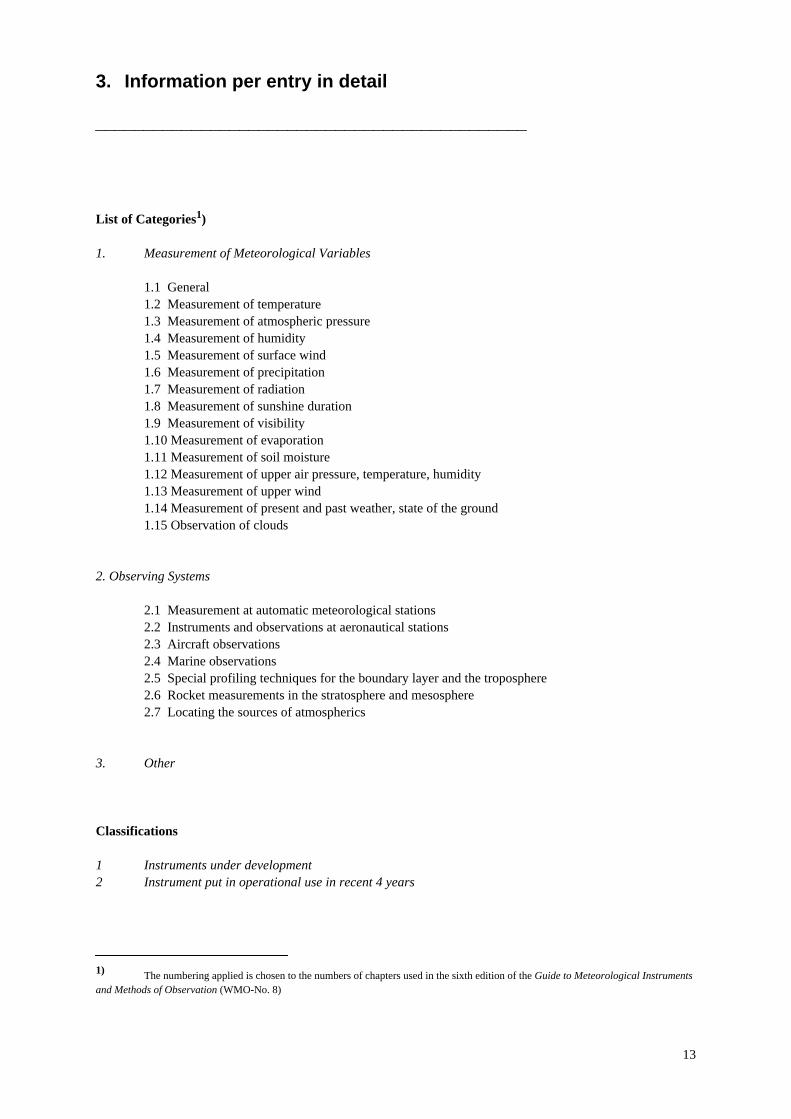
List of Categories1)
1. Measurement of Meteorological Variables
1.1 General1.2 Measurement of temperature1.3 Measurement of atmospheric pressure1.4 Measurement of humidity1.5 Measurement of surface wind1.6 Measurement of precipitation1.7 Measurement of radiation1.8 Measurement of sunshine duration1.9 Measurement of visibility1.10 Measurement of evaporation1.11 Measurement of soil moisture1.12 Measurement of upper air pressure, temperature, humidity1.13 Measurement of upper wind1.14 Measurement of present and past weather, state of the ground1.15 Observation of clouds
2. Observing Systems
2.1 Measurement at automatic meteorological stations2.2 Instruments and observations at aeronautical stations2.3 Aircraft observations2.4 Marine observations2.5 Special profiling techniques for the boundary layer and the troposphere2.6 Rocket measurements in the stratosphere and mesosphere2.7 Locating the sources of atmospherics
3. Other
Classifications
1 Instruments under development2 Instrument put in operational use in recent 4 years
1) The numbering applied is chosen to the numbers of chapters used in the sixth edition of the Guide to Meteorological Instrumentsand Methods of Observation (WMO-No. 8)
13

1.1. InstrumentsInstruments underunder developmentdevelopment
1.1. Measurement of Meteorological Variables
1.1.1. General
-None-
Other entries related to this category:1.1.10.1
1.1.2. Measurement of temperature
Identification number: 1.1.2.1. [003]
Country: Uzbekistan
General information
1. Short identification of the instrument including the parameter measured, or its function: The DTV typeair temperature sensor converts temperature into an electric pulse frequency
2. State of development: Experimental prototype
3. Principle of operation: The air temperature is converted into a voltage using the K1019EMI integralmicroscheme, them into an electric pulse frequency
Main technical characteristics4.1 application: Thermometry and meteorology4.2 measuring range: -45 to +55 °C4.3 uncertainty: ±0.3 °C in the full measurement range4.4 time constant: 1.5 - 2 min.4.5 averaging time: 1 s4.6 reliability: 10,000 hours4.7 interface and output details: Binary code in TTL standard4.8 power requirements: 38±2 V DC4.9 servicing interval: 1 year4.10 other characteristics:
The sensor is made to order with the following output characteristics: F = 10.T °K, F = 10.T °C,F = 10.T °K - F06, where F is the output frequency
Experiences and other information
5. Experience from comparisons and tests performed:The error of the converters based on K1019EMI in the temperature range does not exceed ±0.2°C
6. Costs:6.1 unit cost at factory:6.2 annual operating costs:
7. Name and adress of person responsible for further information:Mr Leonid A. KanaevNPP Gidrometpribor4, Kh. Asomov Street700084 TashkentUzbekistan
Telephone: 34 93 61Telefax: 34 74 89E-mail:URL: http://
8. Major bibliographic references, applicable patents, etc.:
14

Identification number: 1.1.2.2. [053]
Country: United States of America
General information
1. Short identification of the instrument including the parameter measured, or its function: 100-DayDatalogging Weather-Station, Model 40AM166; digitally wind-speed, direction;air temp., rel.humidity;baro. pressure; rainfall, solar-energy (pyranometer) and soil/water temp.
2. State of development: Production scheduled for Spring 1998
3. Principle of operation: Compact probe-outputs converted by A/D modules to serial-data of 8-channel logby rechargeable batteries & solar-panel. Loager stores 72K readings of each, expandable to 144K in point-storage mode (much more in adaptive mode)
Main technical characteristics4.1 application: portable logger for major parameters at any site4.2 measuring range: 0 to 50 m/s, 0 to 360°az, -20 to +55°C, 0 to 100%RH, 800 to 1040 hPa,
rain: unlimited (x0.5mm), 0 to 2.3 mWh/cm2, soil/water temp.: -30 to+50°C
4.3 uncertainty: 3% or less4.4 time constant: 10 seconds or less; wind-wheel d.c.=2.3 m, vane=0.5 m; Anemometer
damping ratio: 0.24.5 averaging time: N/A; computer selectable4.6 reliability: ca. 3 years MTBF (depending upon site conditions)4.7 interface and output details: RS232, 9600 baud4.8 power requirements: 110 V, 60 Hz or 220 V, 50 Hz, for the battery chargers4.9 servicing interval: 100 days4.10 other characteristics:
Compact, rugged-probes (moulded thermoplastic wind-probes, solid-state air temp. and humidity sensorsin self aspirating shelter and solid-state barom. pressure sensor) with a fiberglass reinforced NAMEenclosure for them and electronics/logger/batteries/solar-panel provide lightweight, weather tightness andportability. These mounted probes can optionally be removed for remote exposure. Rain (tilting bucket,with integral funnel and housing) and solar-energy (star pyranometer) probes have signal cables for remotemounting. Optional memory-expansion modules permit unloading loggers’ data and bringing them toIBM-compatible PC (for processing with DOS or Window 95), which allows loggers to remain in the fieldand continue to collect data, instead of removing them and bringing them to the computer.
Experiences and other information
5. Experience from comparisons and tests performed:These probes have been used for over 10 years, to obtain land- or sea-data; this new logger has morememory.
6. Costs:6.1 unit cost at factory:6.2 annual operating costs: US$ 150 (calibr. RH soln.)
7. Name and adress of person responsible for further information:Dr Gerald KahlKahl Scientific Instrument Corp.P.O. Box 1166El Cajon, CA 92022-1166USA
Telephone: (619) 444-2158Telefax: (619) 444-0207E-mail: [email protected]: http://
8. Major bibliographic references, applicable patents, etc.:
15

Identification number: 1.1.2.3. [059]
Country: South Africa
General information
1. Short identification of the instrument including the parameter measured, or its function: Electronicmeasurement of temperature and humidity and displaying of data, as well as storing of data every minuteon a memory module
2. State of development: Final stages before testing
3. Principle of operation: Capacitive humidity sensor Vaisala HMP45 PRT temperature sensor coupled to alogger with display. replaces thermohygrograph
Main technical characteristics4.1 application: Measuring of temperature and humidity electronically and storing of
data on a logger4.2 measuring range: Temp.: -20 to +50°C, hum.: 0 to 100%RH4.3 uncertainty:4.4 time constant:4.5 averaging time:4.6 reliability: Very reliable4.7 interface and output details: Storage module sent to weather office monthly where downloaded onto
PC.4.8 power requirements: 12 V storage battery and solar panel4.9 servicing interval: Monthly to change storage module4.10 other characteristics:
Experiences and other information
5. Experience from comparisons and tests performed:
6. Costs:6.1 unit cost at factory:6.2 annual operating costs: Postage, observers remuneration
7. Name and adress of person responsible for further information:Mr A. (Riaan) J. LourensIrene Weather OfficePrivate Bag X08Irene, 0062Rep. of South Africa
Telephone: (012) 6651589Telefax: (012) 6651594E-mail:URL: http://
8. Major bibliographic references, applicable patents, etc.:
16

Identification number: 1.1.2.4. [105]
Country: United States of America
General information
1. Short identification of the instrument including the parameter measured, or its function: This systemprovides accurate cloud profiles, temperature readings at different elevations, barometric pressure, andcloud coverage percentages. In addition this unit can detect wind speed and direction.
2. State of development: Development of baseline prototype design and validation of existing AIMStechnology.
3. Principle of operation: The instrument measures the water vapour profile based on the vibrational Ramanscattering and the temperature profile based on the rotational Raman scattering. These measurements pro-vide real-time profiles of RF refractivity. Profiles are stored each minute with a vertical resolution of 75meters from the surface to 7 km. The prototype instrument, which includes several subsystems toautomate and monitor operation, has been designed to provide the real-time measurements of profiles.
Main technical characteristics4.1 application: Atmospheric Profile Sensor4.2 measuring range: 75 meters to 7 km to within 20 meters4.3 uncertainty: Below 2 km: less than fraction of a degree; Above 2 km; error increases4.4 time constant: Real time4.5 averaging time:4.6 reliability: Test unit operated continuously for 24 and 36 hour periods with no
complications, Test unit operated in all weather conditions with nocomplications. Tbc instrument features self-calibration, performancetesting, and built-in tests to check many functions
4.7 interface and output details: RS2324.8 power requirements: Standard4.9 servicing interval: Some units feature self-calibrating mechanisms. Service as needed.4.10 other characteristics:
N/A
Experiences and other information
5. Experience from comparisons and tests performed:A prototype instrument was fabricated during FY95/96 and has been deployed on the USS Sumner, a Navysurvey ship, in the Gulf Of Mexico and along the Atlantic coast of Florida during September/October 1996to perform tests and validate its performance, The instrument was used to gather 356 hourly subdirectoriesof data. Measurements were made in all weather conditions and the instrument was available 99% of thetime. The instrument measured water vapour, temperature profiles, true extinction, and ozone profiles.LIDAR data was compared to data from a rawindsonde balloon over same time period and location. TheLIDAR data collected when compared to the balloon data confirmed that the laser error below 2 km isminimal. Above 2 km, however, error increases.
6. Costs:6.1 unit cost at factory:6.2 annual operating costs: N/A
7. Name and adress of person responsible for further information:Mr Donald F. Hayes2045 Bennett Road,Philadelphia, PA, 19116,USA
Telephone: 215-464-9300Telefax: 215-464-9303E-mail: [email protected]: http://warrenind.com
8. Major bibliographic references, applicable patents, etc.:N/A
17

Identification number: 1.1.2.5. [106]
Country: Russian Federation
General information
1. Short identification of the instrument including the parameter measured, or its function: The complex(Module for soil temperature measurements AMT-5) contains one measuring/transmission unit, onecollection unit (common for MT-3) and some sensors, are lowered to selected depths.
2. State of development: The stage of field test
3. Principle of operation: Measured data are stored for further remote readout using infrared channel
Main technical characteristics4.1 application: The main function is soil temperature measurements on 8 levels4.2 measuring range: -50 to +50°C4.3 uncertainty: ±0.2°C4.4 time constant: N/A4.5 averaging time:4.6 reliability:4.7 interface and output details:4.8 power requirements: U = 24/36 VAC; battery: U = 9 V, P = 0.08 W4.9 servicing interval: N/A4.10 other characteristics:
Sensors are designed on semiconductor chip base. Collection unit provides collection/storage/calculationand removal of data to computer and/or digital display. There is an automatic "low" battery control. Thedistance of readout is up to 8 m.
Experiences and other information
5. Experience from comparisons and tests performed:N/A
6. Costs:6.1 unit cost at factory:6.2 annual operating costs:
7. Name and adress of person responsible for further information:Gennadii RybinCental Design Office of Hydrometeorological Instrument Production6, Korolyov st.ObninskKaluga Region 249020Russian Federation
Telephone: (08439) 62303Telefax: (7)(095)2552225E-mail:URL: http://
8. Major bibliographic references, applicable patents, etc.:
18
Identification number: 1.1.2.6. [107]
Country: Russian Federation
General information
1. Short identification of the instrument including the parameter measured, or its function: The complex(Module for air temperature measurements MT-3) contains one measuring/calculation unit, one collectionunit (common for AMT-5), and a pair of dry and wet thermometers on semiconductor chip base.
2. State of development: The stage of field test
3. Principle of operation: Measured data are stored for further remote readout using infrared channel
Main technical characteristics4.1 application: Meteorology4.2 measuring range: -50 to +50°C4.3 uncertainty: ±0.2°C4.4 time constant: N/A4.5 averaging time:4.6 reliability:4.7 interface and output details:4.8 power requirements: U = 24/36 VAC; battery: U = 9 V, P = 0.06 W4.9 servicing interval:4.10 other characteristics:
Measuring/calculation unit provides measurements, minimum/maximum calculation, storage and removalof data to collection unit, which provides collection/storage/calculation and removal of data to computerand/or digital display. The distance of readout is up to 1 m
Experiences and other information
5. Experience from comparisons and tests performed:
6. Costs:6.1 unit cost at factory:6.2 annual operating costs:
7. Name and adress of person responsible for further information:Gennadii RybinCental Design Office of Hydrometeorological Instrument Production6, Korolyov st.ObninskKaluga Region 249020Russian Federation
Telephone: (08439) 62303Telefax: (7)(095)2552225E-mail:URL: http://
8. Major bibliographic references, applicable patents, etc.:
19
Identification number: 1.1.2.7. [108]
Country: Russian Federation
General information
1. Short identification of the instrument including the parameter measured, or its function: The device(Portable thermometer AMT-2) contains one measuring unit, one portable and one stationary sensors andprovides temperature measurements in gaseous, friable and liquid mediums.
2. State of development: The stage of a field test
3. Principle of operation: Measured data can be transmitted in real time regime or stored for further remotereadout.
Main technical characteristics4.1 application: The main function is temperature measurements in an arable layer
during vegetation studies.4.2 measuring range: -30 to +60°C4.3 uncertainty: ±0.5°C4.4 time constant:4.5 averaging time:4.6 reliability:4.7 interface and output details: RS2324.8 power requirements: U = 9 V4.9 servicing interval:4.10 other characteristics:
One measurement unit operates up to 9 stationary sensors with miniature copper resistance thermometer.
Experiences and other information
5. Experience from comparisons and tests performed:
6. Costs:6.1 unit cost at factory:6.2 annual operating costs:
7. Name and adress of person responsible for further information:Gennadii RybinCental Design Office of Hydrometeorological Instrument Production6, Korolyov st.ObninskKaluga Region 249020Russian Federation
Telephone: (08439) 62303Telefax: (7)(095)2552225E-mail:URL: http://
8. Major bibliographic references, applicable patents, etc.:
20

Identification number: 1.1.2.8. [109]
Country: Russian Federation
General information
1. Short identification of the instrument including the parameter measured, or its function: The complex(Thermometer AM 34) contains one readout unit and some measuring/registration underground units.Miniature copper resistance thermometers are lowered to a selected depth of rootlet centre.
2. State of development: The stage of a field test
3. Principle of operation: Measured data are stored for further remote readout using a wireless channel. Thedistance of readout is up to 3m.
Main technical characteristics4.1 application: Agriculture studies.4.2 measuring range: -30 to +40°C4.3 uncertainty: ±0.5°C4.4 time constant:4.5 averaging time:4.6 reliability:4.7 interface and output details:4.8 power requirements:4.9 servicing interval:4.10 other characteristics:
One readout unit can operate up to 9 measuring/registration units. Overhanging elements of design arelacking. Maximum/minimum data are stored between observation periods. Autonomous operation time ofmeasuring/registration units - up to one year.
Experiences and other information
5. Experience from comparisons and tests performed:
6. Costs:6.1 unit cost at factory:6.2 annual operating costs:
7. Name and adress of person responsible for further information:Gennadii RybinCental Design Office of Hydrometeorological Instrument Production6, Korolyov st.ObninskKaluga Region 249020Russian Federation
Telephone: (08439) 62303Telefax: (7)(095)2552225E-mail:URL: http://
8. Major bibliographic references, applicable patents, etc.:
21

Identification number: 1.1.2.9. [182]
Country: Australia
General information
1. Short identification of the instrument including the parameter measured, or its function: Pt100 RTD, soiltemperature probes for a variety of depths: 5, 10, 20, 50 to 100 cm.
2. State of development: Final prototype
3. Principle of operation:
Main technical characteristics4.1 application: Soil temperature4.2 measuring range: -10 to 60°C4.3 uncertainty: 0.2°C4.4 time constant: Grass, 5, 10, 20 cm probe: 50 s (in oil), 50 to 100 cm: 115 cm (in oil)4.5 averaging time: 1 s, 1 min, 10 min4.6 reliability:4.7 interface and output details: 4 wire resistance measurement4.8 power requirements:4.9 servicing interval: unknown4.10 other characteristics:
Experiences and other information
5. Experience from comparisons and tests performed:Laboratory test satisfactory. Field trial commence september 1997.
6. Costs:6.1 unit cost at factory:6.2 annual operating costs:
7. Name and adress of person responsible for further information:Dr Jane WarneGPO Box 1289KMelbourne 3001Australia
Telephone: 61 3 9669 4122Telefax: 61 3 9669 4168E-mail: [email protected]: http://
8. Major bibliographic references, applicable patents, etc.:
22
Identification number: 1.1.2.10. [196]
Country: Philippines
General information
1. Short identification of the instrument including the parameter measured, or its function: Thermometer withThermistor as Sensor: The instrument uses thermistor as the sensing element
2. State of development: Experimentation on the relationship of temperature and resistance is currentlyundertaken
3. Principle of operation: The thermistor changes in resistance as temperature changes
Main technical characteristics4.1 application: To be used for temperature measurement4.2 measuring range: 5°C to 45°C4.3 uncertainty:4.4 time constant: No time constant4.5 averaging time: No averaging time. Only warm up for 5 minutes before taking readings.4.6 reliability: 90%.4.7 interface and output details: The thermistor is connected in series w/ a resistor as one branch of a
Wheatstone bridge circuit and the output of that circuit is coupled to atransistor w/ the meter at the collector circuit.
4.8 power requirements: Two power sources: Regulated 9V at bridge circuit, Regulated 9V attransistor Ckt.
4.9 servicing interval:4.10 other characteristics:
The thermistor thermometer uses three ranges from 5° to 45°C to get more linearized response at theoutput of the bridge circuit so that three resistors are used in series to be selected for each range with thethermistor as one branch and corresponding three resistors similarly switched and selected at the otherbranch of the circuit.
Experiences and other information
5. Experience from comparisons and tests performed:There was no experience yet in actual observation but only in the calibration of the thermistorthermometer.
6. Costs:6.1 unit cost at factory:6.2 annual operating costs:
7. Name and adress of person responsible for further information:Mr Ferdinand Y. BarcenasPhilippine Atmospheric, Geophysical and Astronomical ServicesAdministration (PAGASA)Asiatrust Bank Bldg.1424 Quezon AvenueQuezon City 1104Philippines
Telephone: 929-21-21Telefax:E-mail:URL: http://
8. Major bibliographic references, applicable patents, etc.:- Markus, J.T.: Modern Electronic Circuits Reference manual, pp 1050- Simidchieve, D.A.: Compendium of Lectures Notes on Meteorological Instruments, WMO, pp 55 - 57
Other entries related to this category:1.1.03.2, 1.1.04.1, 1.2.04.2, 2.1.05.92.1.13.3, 2.2.01.2, 2.2.01.3
23
1.1.3. Measurement of atmospheric pressure
Identification number: 1.1.3.1. [025]
Country: The Netherlands
General information
1. Short identification of the instrument including the parameter measured, or its function: The systemconsists of an electronic barometer transducer and datalogger with display for measurement and recordingof barometric pressure
2. State of development: Long term testing phase. The pressure transducer is well known for its stability.
3. Principle of operation: Pressure transducer: Capacitive sensor, Datalogger: Sample interval softwareadjustable
Main technical characteristics4.1 application: Any application where recording of bar. pressure is needed.4.2 measuring range: 600 to 1100 hPa or 800 to 1100 hPa4.3 uncertainty: 0.25%FS4.4 time constant: 10 ms (from 0 to 90% of final output)4.5 averaging time:4.6 reliability:4.7 interface and output details: Output of pressure transducer: 0.1 to 5.1 VDC4.8 power requirements: Pressure transducer: 24 VDC, datalogger: Internal battery4.9 servicing interval: The Wittich & Visser barologger is an integrated system consisting of a
high accuracy and stable pressure sensor, display and one-channeldatalogger with versatile software.
4.10 other characteristics:
Experiences and other information
5. Experience from comparisons and tests performed:
6. Costs:6.1 unit cost at factory:6.2 annual operating costs:
7. Name and adress of person responsible for further information:Mr W.V. (Victor) StruikWittich & Visser BVHandelskade 762288 BG Rijswijkthe Netherlands
Telephone: (070) 3070706Telefax: (070) 3070938E-mail: [email protected]: http://
8. Major bibliographic references, applicable patents, etc.:
24

Identification number: 1.1.3.2. [156]
Country: Finland
General information
1. Short identification of the instrument including the parameter measured, or its function: PTU200 seriesPTU transmitters: atmospheric (surface) pressure + air temperature + relative humidity
2. State of development: To be launched in January 1998.
3. Principle of operation: - uses the BAROCAP® silicon capacitive absolute pressure sensor of Vaisala- uses a Pt100 or a Pt1000 temperature sensor- uses the HUMICAP® thin film polymer humidity sensor- microprocessor electronics performing high order linearization and thermal compensation- available with integrated radiation shield and static pressure head for outdoor use
Main technical characteristics4.1 application: measurement of atmospheric (surface) pressure, air temperature and
relative humidity4.2 measuring range: 500 to 1100 hPa abs. / -40 to +60°C / 0 to 100%RH4.3 uncertainty: ±0.01% reading / ±0.10 hPa / ±0.2 hPa / ±0.3 hPa / ±0.5°C / ±2 to
3%RH4.4 time constant:4.5 averaging time: 1 to 60 s4.6 reliability:4.7 interface and output details: RS232C /TTL level / RS485 / RS422 serial interface; external on/off
triggering possible4.8 power requirements: 10 to 30 VDC / 25 to 50 mA4.9 servicing interval: 1 to 3 years4.10 other characteristics:
- configurable transmitter with several options (accuracy classes, number of pressure transducers etc.)- available with one or two internal pressure transducers for redundant pressure measurement- available with both Pt100 and Pt1000 temperature sensors- available with integrated radiation shield and static pressure head for outdoor use
Experiences and other information
5. Experience from comparisons and tests performed:Long-term stability of atmospheric pressure measurement is generally within ±0.1 hPa per year in the fielduse and typically ±0.05 hPa per year in room temperature use. The HUMICAP® thin film polymerhumidity sensor has a ten-year field record in outdoor measurements in automatic weather station use.
6. Costs:6.1 unit cost at factory:6.2 annual operating costs:
7. Name and adress of person responsible for further information:Mr Pekka JärviVaisala OyP.O.Box 26FIN - 00421 HelsinkiFinland
Telephone: (+358 9) 8949491Telefax: (+358 9) 8949485E-mail: [email protected]: http://www.vaisala.com
8. Major bibliographic references, applicable patents, etc.:Various patents covering the BAROCAP® silicon capacitive absolute pressure sensor and HUMICAP®
thin film polymer humidity sensor of Vaisala.
25

Identification number: 1.1.3.3. [159]
Country: Finland
General information
1. Short identification of the instrument including the parameter measured, or its function: PMB100 seriesbarometer modules: atmospheric (surface) pressure
2. State of development: To be launched in the market in January 1998.
3. Principle of operation: - the module uses the BAROCAP® silicon capacitive absolute pressure sensor ofVaisala- the modules consist of the pressure sensor and basic measurement interface electronics only- a separate temperature sensor is needed for thermal compensation- an EEPROM contains all individual pressure and temperature coefficients of a module- module interfaces directly with an AD converter with input range from 0 to 2.5 VDC- a microprocessor is needed for calculation of compensated pressure
Main technical characteristics4.1 application: measurement of atmospheric (surface) pressure4.2 measuring range: PMB100A: 900 to 1100 hPa / -40 to +60°C
PMB100B: 500 to 1100 hPa / -40 to +60°C4.3 uncertainty: ±0.3 hPa / ±0.5 hPa / ±0.8 hPa, accuracy depending on pressure and
temperature range4.4 time constant:4.5 averaging time: about 1 s4.6 reliability: MTBF4.7 interface and output details: 0 to 2.5 VDC output (+ reference voltage), external on/off triggering
possible4.8 power requirements: 8 to 30 VDC / 3 mA4.9 servicing interval: 1 to 3 years4.10 other characteristics:
- designed for modern systems demanding integrated atmospheric (surface) pressure measurement- the PMB100 modules are intended to be mounted directly on a circuit board
Experiences and other information
5. Experience from comparisons and tests performed:
6. Costs:6.1 unit cost at factory:6.2 annual operating costs: (Information not available)
7. Name and adress of person responsible for further information:Mr Pekka JärviVaisala OyP.O.Box 26FIN - 00421 HelsinkiFinland
Telephone: (+358 9) 8949491Telefax: (+358 9) 8949485E-mail: [email protected]: http://www.vaisala.com
8. Major bibliographic references, applicable patents, etc.:Various patents covering the BAROCAP® silicon capacitive absolute pressure sensor of Vaisala.
Other entries related to this category:1.1.02.21.1.02.41.2.04.22.1.02.12.1.02.8
2.1.02.112.1.02.122.1.02.132.1.02.152.1.02.17
2.1.02.222.1.02.232.1.02.242.1.02.252.1.02.26
2.1.02.272.1.02.282.1.02.292.1.02.302.1.05.12
2.2.01.22.2.01.3
26

1.1.4. Measurement of humidity
Identification number: 1.1.4.1. [007]
Country: United States of America
General information
1. Short identification of the instrument including the parameter measured, or its function: Humidity,temperature & water activity measurement on MEMS silicon die.
2. State of development: Complete patent issued Oct 8, 1996. International patents being pursued. Testpreproduction die performance is confirmed by HMX, Motorola, RdF, Batterle & DERA (England). Diecrat-net manufactured by SMI/EXAR, paciramed by Pelagic.
3. Principle of operation: Hygro shear/stress force of 5 micron polymer coating to contilera beam instermutedwith diffused strain gates. First unit 2 mm square, flow through construction, fail bridge, humidity &temperature. Gager on a common epitaxial layer.
Main technical characteristics4.1 application: Humidity and water activity (aw)4.2 measuring range: 0 - 100 %RH, 0 - 1 aw4.3 uncertainty: < ±1%4.4 time constant: < 1 s (one time constant)4.5 averaging time: N/A4.6 reliability: All Silicon MEMS construction, highest reliability4.7 interface and output details: Humidity full bridge 3500 ohm; 10 mV per Volt. Output 0 - 100%RH,
resolution infinite4.8 power requirements: Microvolt to 10 VDC excitation. AC excitation OK.4.9 servicing interval: Indefinite - No deterioration or drift yet detected4.10 other characteristics:
Experiences and other information
5. Experience from comparisons and tests performed:Hygrometrix and Fenner Associates have been in the manufacture of humidity and water activity sensors &systems based on strain gage technology for 27 years. We have a 30,000 strain gage sensors performancedatabase which includes an extension through the new MEMS technology
6. Costs:6.1 unit cost at factory:6.2 annual operating costs:
7. Name and adress of person responsible for further information:Mr Ralph L. FennerFenner Associates978 Peutz Valley RoadAlpine CA, 91901USA
Telephone: 619-659-0338Telefax: 619-445-7471E-mail: [email protected]: http://www.hygrometrix.com
8. Major bibliographic references, applicable patents, etc.:- (1972) Paper on Cellulose Crystalline Sensors- Patent on MEMS
27

Identification number: 1.1.4.2. [023]
Country: The Netherlands
General information
1. Short identification of the instrument including the parameter measured, or its function: The Lyman-Alphaelements radiate at certain hydrogen emission lines. The absorption at these frequencies of air, and there-fore humidity is measured.
2. State of development: Testing phase.
3. Principle of operation: Hydrogen gas is heated. Lyman-Alpha emission frequencies are created. Radiationat this frequency is absorbed by water vapour in air.
Main technical characteristics4.1 application: Humidity measurement by radiation absorbtion4.2 measuring range: 0 to 100%RH4.3 uncertainty: 2%RH4.4 time constant: Approx. 5 ms4.5 averaging time:4.6 reliability:4.7 interface and output details: 0 to 10 V4.8 power requirements: Max. 5 W power consumption4.9 servicing interval:4.10 other characteristics:
The new Lyman-Alpha elements are the sources for the Lyman-Alpha hygrometer. They have beendesigned for longer life cycle in comparison with the existing elements.
Experiences and other information
5. Experience from comparisons and tests performed:
6. Costs:6.1 unit cost at factory:6.2 annual operating costs:
7. Name and adress of person responsible for further information:Mr W.V. (Victor) StruikWittich & Visser BVHandelskade 762288 BG Rijswijkthe Netherlands
Telephone: (070) 3070706Telefax: (070) 3070938E-mail: [email protected]: http://
8. Major bibliographic references, applicable patents, etc.:
28
Identification number: 1.1.4.3. [024]
Country: The Netherlands
General information
1. Short identification of the instrument including the parameter measured, or its function: The Wittich &Visser leaf-wetness sensors detects condensation on a surface.
2. State of development: Prototypes have been tested
3. Principle of operation: Condensation on a surface is detected by a beam of infrared radiation directed onthe glass measurement surface. the diffusion is an indicator for leaf-wetness.
Main technical characteristics4.1 application: Leaf-wetness measurement in greenhouses4.2 measuring range: Near 100%RH4.3 uncertainty:4.4 time constant: Fast response depending on glass thickness4.5 averaging time:4.6 reliability:4.7 interface and output details: Output: 750 to 1250 mV4.8 power requirements: 220 VAC, 50 Hz or 12 VDC4.9 servicing interval:4.10 other characteristics:
The new leaf-wetness sensor measures surface wetness by means of infrared reflection on a measurementsurface. The probe is intended for use in a greenhouse environment. Apart from surface wetness the sensormay be used to detect imminent surface wetness.
Experiences and other information
5. Experience from comparisons and tests performed:
6. Costs:6.1 unit cost at factory:6.2 annual operating costs:
7. Name and adress of person responsible for further information:Mr W.V. (Victor) StruikWittich & Visser BVHandelskade 762288 BG Rijswijkthe Netherlands
Telephone: (070) 3070706Telefax: (070) 3070938E-mail: [email protected]: http://
8. Major bibliographic references, applicable patents, etc.:
29

Identification number: 1.1.4.4. [028]
Country: United States of America
General information
1. Short identification of the instrument including the parameter measured, or its function: This instrumentcalled a saturation hygrometer measures ambient relative humidity (RH) in a range centred about the satu-ration vapour pressure where RH = 100%. Measures of supersaturation (RH > 100%) are obtained.
2. State of development: First prototype constructed and flown on a motorized airship
3. Principle of operation: Condensation nuclei located on a thermally-thin and hydrophobic substrate changetheir size with RH; size change is sensed optically. For conditions of RH > 100% an infrared heater keepsthe solution droplets at a constant size; the temperature increase of the substrate is directly proportional tothe supersaturation
Main technical characteristics4.1 application: Research in cloud physics4.2 measuring range: 95% to 105% RH4.3 uncertainty: 0.02% at RH = 100%; 1% at RH = 97%4.4 time constant: 0.5 s4.5 averaging time: N/A4.6 reliability: Substrate is relatively short-lived, but expendable and replaceable4.7 interface and output details: Two analog channels; one for RH < 100%, one for RH > 100%.4.8 power requirements: 10 W4.9 servicing interval: Unknown4.10 other characteristics:
The saturation hygrometer is calibrated in the field by immersing the probe into an insulated box in whichRH is kept at 100%. This fixes the operation point of the hygrometer, which has a channel for measuringRH < 100%, and a second channel for measuring RH > 100%. The former channel obtains a measure ofRH by observing optically the change in the scattered light by the solution droplets formed on thecondensation nuclei, while the latter measures the supersaturation by relating the temperature increase ofthe hygrometer substrate to the vapour pressure. A thermo-optical servo loop keeps the droplets at their100% size during periods of supersaturation. The hygrometer is sensitive to the surrounding black-bodyradiation, and so is protected by a thermally-thin radiation shield.
Experiences and other information
5. Experience from comparisons and tests performed:Comparison of supersaturations generated by a large thermal-gradient diffusion chamber (continuousflow), and supersaturations calculated from the temperature increase of the hygrometer substrate agreedwell. Measurements in fog showed stable operation and lack of hysteresis effects in the hygrometer.
6. Costs:6.1 unit cost at factory:6.2 annual operating costs: Nil
7. Name and adress of person responsible for further information:Dr Hermann GerberGerber Scientific Inc.1643 Bentana WayReston, VA 20190USA
Telephone: 703-742-9844Telefax: 703-742-3374E-mail: [email protected]: http://
8. Major bibliographic references, applicable patents, etc.:- Gerber, H, 1994: "Hygrometer for measurement of relative humidity in clouds". Final Report SBIR PhaseI No. 9261243, pp. 19 (National Science Foundation, Washington, DC, USA)
30

Identification number: 1.1.4.5. [102]
Country: United States of America
General information
1. Short identification of the instrument including the parameter measured, or its function: The instrumentmeasures the relative humidity and temperature of air at the location of the RH and T transducers. This airsample is ambient air that has been heated to lower its relative humidity. The temperature of the actualambient air is also measured. The RH and dewpoint of the ambient air is then computed by the instrumentcomputer system
2. State of development: Commercial instrument purchased. Test and evaluation being planned
3. Principle of operation:
Main technical characteristics4.1 application: Ambient air is heated by an electrical element before the air sample
reaches a small relative humidity transducer. The dewpoint of the airsample is calculated using the measured values of RH and T. Therelative humidity of the ambient air is also calculated based on themeasured value of dewpoint and air temperature.
4.2 measuring range: relative humidity measurements4.3 uncertainty: 20%RH to 100%RH4.4 time constant: ±2%RH4.5 averaging time: Not known4.6 reliability: Not known4.7 interface and output details: Digital, serial RS232/4854.8 power requirements: Undermined, but > 1 W4.9 servicing interval: 1 year4.10 other characteristics:
Experiences and other information
5. Experience from comparisons and tests performed:No field experience at NDBC
6. Costs:6.1 unit cost at factory:6.2 annual operating costs: US$ 300
7. Name and adress of person responsible for further information:Dr Eduardo MichelenaNational Data Buoy CentreStennis Space Centre, MS 39529USA
Telephone: 601-688-1715Telefax: 601-688-3153E-mail: [email protected]: http://
8. Major bibliographic references, applicable patents, etc.:Vaisala technical manual for humidity sensors
Other entries related to this category:1.1.02.21.1.02.31.1.02.41.1.03.21.2.05.12.1.01.12.1.02.12.1.02.2
2.1.02.32.1.02.52.1.02.62.1.02.102.1.02.112.1.02.122.1.02.132.1.02.15
2.1.02.162.1.02.172.1.02.192.1.02.202.1.02.212.1.02.232.1.02.242.1.02.25
2.1.02.262.1.02.272.1.02.282.1.02.292.1.02.302.1.02.312.2.01.22.2.01.3
31

1.1.5. Measurement of surface wind
Identification number: 1.1.5.1. [031]
Country: United States of America
General information
1. Short identification of the instrument including the parameter measured, or its function: AirportSurveillance Radar, ASR-9
2. State of development: Prototype successfully tested, entering production phase
3. Principle of operation: Doppler weather radar technology applied to existing Air Traffic Control Radar.Automated image analysis to detect wind shear and estimate storm motion
Main technical characteristics4.1 application: Wind shear detection and storm tracking4.2 measuring range: 0 to 60 nmi4.3 uncertainty:4.4 time constant: 30 s (update period)4.5 averaging time: 30 s4.6 reliability: > 0.9 availability and probability of detection4.7 interface and output details: Input from ASR-9 output to dedicated displays4.8 power requirements: Approx. 2000 W4.9 servicing interval: Approx. 3 months4.10 other characteristics:
Experiences and other information
5. Experience from comparisons and tests performed:Prototype operational testing began 1990 and has continued thereafter: Very good operational acceptanceby Air Traffic Controller’s exposed to the prototype system products.
6. Costs:6.1 unit cost at factory:6.2 annual operating costs: Approx. US$ 25,000
7. Name and adress of person responsible for further information:Dr Mark Weber,Massachusetts Institute of Technology,Lincoln Laboratory244 Wood streetLexington, MA 02173-9108USA
Telephone: 617-981-7434Telefax: 617-981-0632E-mail: [email protected]: http://
8. Major bibliographic references, applicable patents, etc.:- "Low Altitude Wind Shear Detection using Airport Surveillance Radars", IEEE AES 10(1995)3-5- "ASR-9 WSP Provides Significant and Affordable Enhancement to Terminal Weather Surveillance",Journal of ATC 38(1996)41-45
32

Identification number: 1.1.5.2. [055]
Country: United States of America
General information
1. Short identification of the instrument including the parameter measured, or its function: 100-DayDatalogging Anemograph, Model 02BM315; digitally records wind speed (0-50 m/s) and direction (0-360°), 36K of each (min.)
2. State of development: Production scheduled for Fall, 1997
3. Principle of operation: 3-cup anemometer produces AC voltage, vane-coupled potentiometer produces DCvoltage from circuit, both converted by A/D modules to serial-data of logger, powered by rechargeablebatteries. Logger stores 36,000 readings of each (expandable to 324,000).
Main technical characteristics4.1 application: Collection of wind data in remote locations4.2 measuring range: speed: 0 to 50 m/s; direction: 0 to 360° azimuth4.3 uncertainty: 0.5%4.4 time constant: Cup-wheel distance-constant = 2.3 m; vane d.d. = 0.5 m4.5 averaging time: N/A4.6 reliability: ca. 5 years MTBF (depending upon site-conditions)4.7 interface and output details: RS232, 9600 baud4.8 power requirements: 110 V, 60 Hz or 220 V, 50 Hz, for battery chargers4.9 servicing interval: 100 days4.10 other characteristics:
Moulded thermoplastic probe components and fiberglass reinforced NEMA enclosure for elec-tronics/logger/batteries provide exceptionally good corrosion-resistance, as well as lightweight (for optimalsensor-response and portability) and weathertight integrity (for use in any climate). Optionally, probes canbe removed from the enclosure for exposure some distance away. Optional memory-expansion modulecan be used to unload logger’s data and bring them to IBM compatible PC (for processing with DOS 3.0 orWindows 95), which allows logger to remain in the field and continue to collect data.
Experiences and other information
5. Experience from comparisons and tests performed:These probes have been used for over 10 years, to obtain data on land or at sea; this new logger has morememory than the original.
6. Costs:6.1 unit cost at factory:6.2 annual operating costs: Nil (batteries, wicks)
7. Name and adress of person responsible for further information:Dr Gerald KahlKahl Scientific Instrument Corp.P.O. Box 1166El Cajon, CA 92022-1166USA
Telephone: (619) 444-2158Telefax: (619) 444-0207E-mail: [email protected]: http://
8. Major bibliographic references, applicable patents, etc.:
33

Identification number: 1.1.5.3. [069]
Country: China
General information
1. Short identification of the instrument including the parameter measured, or its function:Anemorumbometer with standard wind pipe to identify.
2. State of development: EN Anemorumbometer is under development, and tested in the weather stationEY1 Electrical transmission anemorumbometer is put into operational use
3. Principle of operation: Digital display, with automatic printing and output port are in the instrument
Main technical characteristics4.1 application: Used in meteorological station, harbor, port4.2 measuring range: Wind direction: 0 to 360°, wind speed: 0.5 to 70 m/s4.3 uncertainty:4.4 time constant:4.5 averaging time:4.6 reliability:4.7 interface and output details:4.8 power requirements: 220 VAC, 50 z or 12 VDC4.9 servicing interval: 12 months4.10 other characteristics:
EL Electrical Contact AnemorumbometerEY1 Electrical Transmission AnemorumbometerEY1-2B Electrical Transmission Alarm InstrumentEDE-1A Hand held Digital AnemometerZZ6-4 Ship Meteorological Set
Experiences and other information
5. Experience from comparisons and tests performed:
6. Costs:6.1 unit cost at factory:6.2 annual operating costs:
7. Name and adress of person responsible for further information:Shanghai Meteorological Instrument Factory270, Chuan Gong RoadShanghaiP.R. China
Telephone: (021) 56636730Telefax: (021) 56638934E-mail:URL: http://
8. Major bibliographic references, applicable patents, etc.:
34
Identification number: 1.1.5.4. [093]
Country: United States of America
General information
1. Short identification of the instrument including the parameter measured, or its function: HOLODAR@Model 700 remotely measures atmospheric turbulence and wind parameters along a single path using astable or fixed location.
2. State of development: Working prototype
3. Principle of operation: Measures crosswinds and atmospheric turbulence (atmospheric, pollution tracking,weapons systems, etc) and fluid flows. This device with its lange optics holographic filters achievesgreater range and resolution than other sensors.
Main technical characteristics4.1 application: measuring wind speed, wind direction and turbulence4.2 measuring range: five hundred to ten thousand meters4.3 uncertainty: 8 to 10%4.4 time constant: 10 s4.5 averaging time: 30 s4.6 reliability: high reliability and no moving parts4.7 interface and output details: to be determined by customer needs4.8 power requirements: approximately 10 W4.9 servicing interval: every six months a service check4.10 other characteristics:
Experiences and other information
5. Experience from comparisons and tests performed:N/A
6. Costs:6.1 unit cost at factory:6.2 annual operating costs: US$ 500 to US$ 1,000
7. Name and adress of person responsible for further information:Mr John F. DoveDove Electronics, Inc.227 Liberty PlazaRome, NY 13440USA
Telephone: 315-336-0230Telefax: 315-336-2080E-mail: [email protected]: http://
8. Major bibliographic references, applicable patents, etc.:- Churnside, J.H., S.G. Hanson, and J.J. Wilson (1995): "Determination of Ocean Wave Spectra fromImages of Backscattered Incoherent Light," Appl.Opt. 34(1995)962-968- Hanson, S.G., J.H. Churnside and J.J. Wilson (1994): "Remote Sensing of Wind Velocity and Strength ofRefractive Turbulence using a Two-Spatial Filter Receiver," Appl. Opt. 33(1994)5859-5868
35

Identification number: 1.1.5.5. [094]
Country: United States of America
General information
1. Short identification of the instrument including the parameter measured, or its function: MicroHOLODAR@ Model 600 measures atmospheric turbulence and wind parameters (i.e., wind shear).
2. State of development: Working prototype
3. Principle of operation: Measures crosswinds and atmospheric turbulence. Features small size, ease oftransport and set-up and low power requirement (1 W) allowing for on-site field applications (buildingairflow, sports, military applications, snow barrier design)
Main technical characteristics4.1 application: measuring wind speed, wind direction and turbulence4.2 measuring range: to 1 km4.3 uncertainty: 5 to 10%4.4 time constant:4.5 averaging time: 30 s4.6 reliability: highly reliable, no moving parts4.7 interface and output details: to be determined bv customer needs4.8 power requirements: 1 W4.9 servicing interval: every six months a service check4.10 other characteristics:
Experiences and other information
5. Experience from comparisons and tests performed:N/A
6. Costs:6.1 unit cost at factory:6.2 annual operating costs: US$ 500
7. Name and adress of person responsible for further information:Mr John F. DoveDove Electronics, Inc.227 Liberty PlazaRome, NY 13440USA
Telephone: 315-336-0230Telefax: 315-336-2080E-mail: [email protected]: http://
8. Major bibliographic references, applicable patents, etc.:- Churnside, J.H., S.G. Hanson, and J.J. Wilson (1995): "Determination of Ocean Wave Spectra fromImages of Backscattered Incoherent Light," Appl.Opt. 34(1995)962-968- Hanson, S.G., J.H. Churnside and J.J. Wilson (1994): "Remote Sensing of Wind Velocity and Strength ofRefractive Turbulence using a Two-Spatial Filter Receiver," Appl. Opt. 33(1994)5859-5868
36

Identification number: 1.1.5.6. [095]
Country: United States of America
General information
1. Short identification of the instrument including the parameter measured, or its function: PassiveHOLODAR® Model 500 remotely measures atmospheric turbulence and wind parameters along a singlepath using a stable or fixed location.
2. State of development: Working prototype
3. Principle of operation: Measures crosswinds and atmospheric turbulence (atmospheric, pollution tracking,weapons systems, etc.) and fluid flows without the use of an active transmission device. It makes use ofwavelet transforms, neural networks, advanced optics and digital imaging technologies
Main technical characteristics4.1 application: measuring wind speed, wind direction and turbulence4.2 measuring range: 1 km4.3 uncertainty: 10%4.4 time constant:4.5 averaging time: 30 s4.6 reliability: highly reliable, no moving parts4.7 interface and output details: to be determined by customer needs4.8 power requirements: 10W4.9 servicing interval: every six months a service check4.10 other characteristics:
Experiences and other information
5. Experience from comparisons and tests performed:N/A
6. Costs:6.1 unit cost at factory:6.2 annual operating costs: US$ 1,000
7. Name and adress of person responsible for further information:Mr John F. DoveDove Electronics, Inc.227 Liberty PlazaRome, NY 13440USA
Telephone: 315-336-0230Telefax: 315-336-2080E-mail: [email protected]: http://
8. Major bibliographic references, applicable patents, etc.:- Churnside, J.H., S.G. Hanson, and J.J. Wilson (1995): "Determination of Ocean Wave Spectra fromImages of Backscattered Incoherent Light," Appl.Opt. 34(1995)962-968- Hanson, S.G., J.H. Churnside and J.J. Wilson (1994): "Remote Sensing of Wind Velocity and Strength ofRefractive Turbulence using a Two-Spatial Filter Receiver," Appl. Opt. 33(1994)5859-5868
37

Identification number: 1.1.5.7. [096]
Country: United States of America
General information
1. Short identification of the instrument including the parameter measured, or its function: Active Wind AlertModel 400 remotely measures atmospheric turbulence and wind parameters along a single path using astable or fixed location.
2. State of development: Working prototype
3. Principle of operation: Provides wind alert or high wind warning to drivers on highways, bridges, hills,mountains, valleys, canyons and other high wind or snow areas. Uses light emitting diodes instead oflasers
Main technical characteristics4.1 application: measuring wind speed, wind direction and turbulence4.2 measuring range: 100 m4.3 uncertainty: 10%4.4 time constant:4.5 averaging time: 30 s4.6 reliability: highly reliable, no moving parts4.7 interface and output details: to he determined by customer needs4.8 power requirements: 2 W4.9 servicing interval: every six months a service check4.10 other characteristics:
Experiences and other information
5. Experience from comparisons and tests performed:N/A
6. Costs:6.1 unit cost at factory:6.2 annual operating costs: US$ 200
7. Name and adress of person responsible for further information:Mr John F. DoveDove Electronics, Inc.227 Liberty PlazaRome, NY 13440USA
Telephone: 315-336-0230Telefax: 315-336-2080E-mail: [email protected]: http://
8. Major bibliographic references, applicable patents, etc.:- Churnside, J.H., S.G. Hanson, and J.J. Wilson (1995): "Determination of Ocean Wave Spectra fromImages of Backscattered Incoherent Light," Appl.Opt. 34(1995)962-968- Hanson, S.G., J.H. Churnside and J.J. Wilson (1994): "Remote Sensing of Wind Velocity and Strength ofRefractive Turbulence using a Two-Spatial Filter Receiver," Appl. Opt. 33(1994)5859-5868
38

Identification number: 1.1.5.8. [101]
Country: United States of America
General information
1. Short identification of the instrument including the parameter measured, or its function: Ultrasonic typeanemometer that uses a magnetometer for north reference and a microprocessor for extensive dataprocessing internal to the sensor
2. State of development: Definition of design 90% completed. Fabrication of prototype instrument 10%completed. Testing of component systems 80% completed.
3. Principle of operation: A three axis ultrasonic anemometer bas been modified so that its microprocessorcan combine the direction reference from an attached magnetometer so that wind direction is correctlyreported even when the instrument is pitching, rolling, and yawing wren mounted on a buoy.
Main technical characteristics4.1 application: Wind measurement on buoys at sea4.2 measuring range: 0 to 80 m (s/speed) 0 to 360° (direction)4.3 uncertainty: ± 5% of reading4.4 time constant: not determined4.5 averaging time: variable (as needed) ¼ second to 10 minutes4.6 reliability: 90%4.7 interface and output details: digital output (rs485) of instantaneous measurement and of processed
data consisting of averaged and peak wind values4.8 power requirements: 9 to 30 VDC, 90 mA4.9 servicing interval: 3 years4.10 other characteristics:
Internal microprocessor used to control the operation of the ultrasonic transducers, make time of travel(sound pulse) measurements, make trigonometric and matric transformations, format data output, averagethe instantaneous 3 axis wind measurement, etc.
Experiences and other information
5. Experience from comparisons and tests performed:Very good comparison with collocated wind sensors of the propeller-vane type (r.M. Young wind monitor
6. Costs:6.1 unit cost at factory:6.2 annual operating costs: us$ 300
7. Name and adress of person responsible for further information:mr Ralph Dagnallnational data buoy centrestennis space centre, ms 39529usa
Telephone: 601-688-3153Telefax: 601-688-3153E-mail: [email protected]: http://
8. Major bibliographic references, applicable patents, etc.:Gill instruments ltd, uk: wind master ultrasonic anemometer manual
39

Identification number: 1.1.5.9. [149]
Country: Finland
General information
1. Short identification of the instrument including the parameter measured, or its function: MultichannelAveraging Wind Display for aviation
2. State of development: Prototype passed
3. Principle of operation: Multichannel averaging wind display for heavy duty use e.g. aviation - wind speed,gusts and direction w. variance, cross/tail wind components, configurable site id. High intensity LEDtechnology w. automatic brightness control. On-line configurable. Serial i/o for sensors and transmitters.Slim line, mountable on desk, wall, ceiling or panel.
Main technical characteristics4.1 application: Aviation4.2 measuring range: any4.3 uncertainty: sensor/transmitter dependent4.4 time constant:4.5 averaging time: configurable4.6 reliability:4.7 interface and output details: serial i/o4.8 power requirements: 10 to 30 VDC4.9 servicing interval:4.10 other characteristics:
Heavy duty multichannel averaging wind display for aviation use
Experiences and other information
5. Experience from comparisons and tests performed:
6. Costs:6.1 unit cost at factory:6.2 annual operating costs:
7. Name and adress of person responsible for further information:Mr. Tapani TiusanenVaisala OyP.O Box 26FIN-00421 HelsinkiFinland
Telephone: (+358 9) 8949 603Telefax: (+358 9) 8949 568E-mail: [email protected]: http://www.vaisala.com
8. Major bibliographic references, applicable patents, etc.:
40
Identification number: 1.1.5.10. [150]
Country: Finland
General information
1. Short identification of the instrument including the parameter measured, or its function: Digital Wind/TUtransmitter
2. State of development: Design
3. Principle of operation: Digital wind, temperature and humidity transmitter with flexible communicationsupport.
Main technical characteristics4.1 application: Wind and T/U-measurements in meteorology4.2 measuring range: sensors dependent4.3 uncertainty: sensor/transmitter dependent; signals are digitized at site4.4 time constant:4.5 averaging time: not specified4.6 reliability:4.7 interface and output details: serial i/o4.8 power requirements: not specified4.9 servicing interval:4.10 other characteristics:
Heavy duty digital transmitter with wide operating temperature range.
Experiences and other information
5. Experience from comparisons and tests performed:
6. Costs:6.1 unit cost at factory:6.2 annual operating costs:
7. Name and adress of person responsible for further information:Mr. Tapani TiusanenVaisala OyP.O Box 26FIN-00421 HelsinkiFinland
Telephone: (+358 9) 8949 603Telefax: (+358 9) 8949 568E-mail: [email protected]: http://www.vaisala.com
8. Major bibliographic references, applicable patents, etc.:
41

Identification number: 1.1.5.11. [151]
Country: Finland
General information
1. Short identification of the instrument including the parameter measured, or its function: MultichannelAveraging Wind, Temperature and Humidity Display
2. State of development: Design
3. Principle of operation: Multichannel averaging WTU display - wind speed and direction, temperature andhumidity. High intensity LED technology w. automatic brightness control. On-line configurable. Digital,analog and serial i/o for sensors and transmitters. Slim line, mountable on desk, wall, ceiling or panel.
Main technical characteristics4.1 application: Emergency Response4.2 measuring range: sensor/transmitter dependent4.3 uncertainty: sensor/transmitter dependent4.4 time constant:4.5 averaging time: not specified4.6 reliability:4.7 interface and output details: digital, analog and serial i/o4.8 power requirements: 10.5 to 15.5 VDC4.9 servicing interval:4.10 other characteristics:
General purpose averaging wind display with temperature and humidity readings for multiple siteapplications
Experiences and other information
5. Experience from comparisons and tests performed:
6. Costs:6.1 unit cost at factory:6.2 annual operating costs:
7. Name and adress of person responsible for further information:Mr. Tapani TiusanenVaisala OyP.O Box 26FIN-00421 HelsinkiFinland
Telephone: (+358 9) 8949 603Telefax: (+358 9) 8949 568E-mail: [email protected]: http://www.vaisala.com
8. Major bibliographic references, applicable patents, etc.:
42
Identification number: 1.1.5.12. [152]
Country: Finland
General information
1. Short identification of the instrument including the parameter measured, or its function: Combined WindSensor for low power applications.
2. State of development: Design
3. Principle of operation: Cup wheel and vane are integrated to one unit. Passive signals; potentiometer w.cap or no cap for wind direction and switch for wind speed. For very low power applications.
Main technical characteristics4.1 application: Horizontal surface wind measurement4.2 measuring range: speed 0.5 to 60 m/s, direction 0 to 360°4.3 uncertainty:4.4 time constant:4.5 averaging time:4.6 reliability:4.7 interface and output details: analog (passive)4.8 power requirements: very low4.9 servicing interval: check once in a year4.10 other characteristics:
Low power, low price combined wind sensor
Experiences and other information
5. Experience from comparisons and tests performed:
6. Costs:6.1 unit cost at factory:6.2 annual operating costs:
7. Name and adress of person responsible for further information:Mr. Tapani TiusanenVaisala OyP.O Box 26FIN-00421 HelsinkiFinland
Telephone: (+358 9) 8949 603Telefax: (+358 9) 8949 568E-mail: [email protected]: http://www.vaisala.com
8. Major bibliographic references, applicable patents, etc.:
Other entries related to this category:1.1.02.21.1.02.41.2.04.21.3.00.62.1.02.72.1.02.112.1.02.122.1.02.132.1.02.142.1.02.152.1.02.172.1.02.22
2.1.02.232.1.02.242.1.02.252.1.02.262.1.02.272.1.02.282.1.02.292.1.02.302.2.01.22.2.01.32.2.04.1
43
1.1.6. Measurement of precipitation
Identification number: 1.1.6.1. [063]
Country: United Kingdom of Great Britain and Northern Ireland
General information
1. Short identification of the instrument including the parameter measured, or its function: AcousticPrecipitation Detector
2. State of development: Initial design for feasibility
3. Principle of operation: Detection of precipitation type using acoustic signature on rigid or water surface
Main technical characteristics4.1 application: Use at automatic weather stations4.2 measuring range:4.3 uncertainty:4.4 time constant:4.5 averaging time:4.6 reliability:4.7 interface and output details:4.8 power requirements:4.9 servicing interval:4.10 other characteristics:
A low cost sensor to complement other precipitation detectors
Experiences and other information
5. Experience from comparisons and tests performed:
6. Costs:6.1 unit cost at factory:6.2 annual operating costs:
7. Name and adress of person responsible for further information:Mr David HattonThe Met. Office, MET O(OLA)1aBeaufort Park, EasthampsteadWokingham, Berkshire RG40 3DNGreat Britain
Telephone: +44 (0)1344 855831Telefax: +44 (0)1344 855897E-mail: [email protected]: http://www.meto.gov.uk
8. Major bibliographic references, applicable patents, etc.:
44
Identification number: 1.1.6.2. [064]
Country: United Kingdom of Great Britain and Northern Ireland
General information
1. Short identification of the instrument including the parameter measured, or its function: Remote VideoCamera Observing System
2. State of development: Feasibility study complete, initial trials underway
3. Principle of operation: Commercial surveillance camera + image compression & transmission technologyusing frequently updated still images transmitted over landlines (ISDN, PSTN, etc.)
Main technical characteristics4.1 application: Monitor weather + enhance automated measurements.4.2 measuring range: Visible light at present4.3 uncertainty:4.4 time constant: 1 to 5 s update4.5 averaging time: Instantaneous4.6 reliability:4.7 interface and output details: Data adaptor + modem over ISDN/PSTN4.8 power requirements:4.9 servicing interval:4.10 other characteristics:
Cameras have remote control for pan, tilt, zoom, focus, iris aperture. Daylight operation initially - use ofartificial lighting and low light cameras being developed. manual interpretation of images initially -automatic analysis of images being developed
Experiences and other information
5. Experience from comparisons and tests performed:Internal feasibility study completed
6. Costs:6.1 unit cost at factory:6.2 annual operating costs:
7. Name and adress of person responsible for further information:Mr David HattonThe Met. Office, MET O(OLA)1aBeaufort Park, EasthampsteadWokingham, Berkshire RG40 3DNGreat Britain
Telephone: +44 (0)1344 855831Telefax: +44 (0)1344 855897E-mail: [email protected]: http://www.meto.gov.uk
8. Major bibliographic references, applicable patents, etc.:
45

Identification number: 1.1.6.3. [092]
Country: Pakistan
General information
1. Short identification of the instrument including the parameter measured, or its function: Plastic coating ofraingauge
2. State of development: In test
3. Principle of operation: See 4.10 (Other characteristics)
Main technical characteristics4.1 application: Precipitation measurements4.2 measuring range: N/A4.3 uncertainty: N/A4.4 time constant: N/A4.5 averaging time: N/A4.6 reliability: N/A4.7 interface and output details: N/A4.8 power requirements: N/A4.9 servicing interval: N/A4.10 other characteristics:
Due to Plastic coating the raingauge bottle (receiver) will be protected from rusting (due to weatherconditions) and will have long live.
Experiences and other information
5. Experience from comparisons and tests performed:
6. Costs:6.1 unit cost at factory:6.2 annual operating costs:
7. Name and adress of person responsible for further information:Dr Qamar-Uz-Zaman ChaudhryPakistan Meteorological DepartmentHeadquarters OfficeMeteorological ComplexP.O. Box No. 8485University RoadKarachi - 75270Pakistan
Telephone: (92-21) 8112223Telefax: (92-21) 8112885/8112887E-mail: [email protected]: http://
8. Major bibliographic references, applicable patents, etc.:
46

Identification number: 1.1.6.4. [201]
Country: Canada
General information
1. Short identification of the instrument including the parameter measured, or its function: POSS(Precipitation Occurrence Sensor System) - measures precipitation type and intensity.
2. State of development: Commercialized with Andrew Antenna Canada Ltd. Technology upgrade for Front-End Processor under review. Additional signal processing and software being considered to reportaccumulated precipitation and more complete present weather reports. Drop size distribution underconsideration.
3. Principle of operation: Precipitation fall velocity spectrum obtained using a bistatic 10.535 GHz Dopplerradar. This spectrum is analyzed to determine presence, type and intensity of precipitation.
Main technical characteristics4.1 application: Automation of present weather observations.4.2 measuring range: Very light to very heavy precipitation.4.3 uncertainty:4.4 time constant: 1 min4.5 averaging time: 1 min4.6 reliability:4.7 interface and output details: Digital output from a front-end processor. Designed to operate with an
automatic weather station.4.8 power requirements: 110 VAC4.9 servicing interval: Approximately 1 year4.10 other characteristics:
Designed to operate in the diverse Canadian Climate with our AWOS (Automatic Weather ObservingSystem) also known as READAC (Remote Environmental Automatic Data Acquisition Concept).
Experiences and other information
5. Experience from comparisons and tests performed:Details have been provided at various meteorological conferences.
6. Costs:6.1 unit cost at factory:6.2 annual operating costs: N/A
7. Name and adress of person responsible for further information:Earle RobinsonAtmospheric Environment Service,Environment Canada4905 Dufferin St.Downsview, Ont.M3H 5T4Canada
Telephone: 416-739-4586Telefax: 416-739-4261E-mail: [email protected]: http://
8. Major bibliographic references, applicable patents, etc.:Being manufactured by Andrew Canada Inc., Fax #: 905-668-8590
Other entries related to this category:1.1.02.21.1.02.41.1.05.11.3.00.62.1.02.11
2.1.02.132.1.02.152.1.02.172.1.02.222.1.02.23
2.1.02.242.1.02.252.1.02.262.1.02.272.1.02.28
2.1.02.292.1.02.302.1.13.22.3.00.4
47
1.1.7. Measurement of radiation
Identification number: 1.1.7.1. [006]
Country: Uzbekistan
General information
1. Short identification of the instrument including the parameter measured, or its function: The sunshinesensor (SS) GF-1 determines the periods of time in which the difference between total and diffuse radiationexceed a given value.
2. State of development: Experimental prototype
3. Principle of operation: The instrument produces a logical "yes" signal when the difference between theopen and shaded pyranometers’ signal exceeds 100 - 120 W/m2
Main technical characteristics4.1 application: Actionometry at automatic stations4.2 measuring range: Illumination 50 - 200 W/m2
4.3 uncertainty: ±5% about he threshold in the temperature range4.4 time constant: nil4.5 averaging time: nil4.6 reliability: 10,000 hours4.7 interface and output details: Output signal in TTL standard4.8 power requirements: 38 ± 2 V DC4.9 servicing interval: 1 year4.10 other characteristics:
Operating temperature range: -40 to +55 °C
Experiences and other information
5. Experience from comparisons and tests performed:Satisfactory compatibility of results with parallel observations using the Campbell-Stokes instrument.
6. Costs:6.1 unit cost at factory:6.2 annual operating costs: -
7. Name and adress of person responsible for further information:Mr Leonid A. KanaevNPP Gidrometpribor4, Kh. Asomov Street700084 TashkentUzbekistan
Telephone: 34 93 61Telefax: 34 74 89E-mail:URL: http://
8. Major bibliographic references, applicable patents, etc.:-
48

Identification number: 1.1.7.2. [002]
Country: Uzbekistan
General information
1. Short identification of the instrument including the parameter measured, or its function: The PPL-1 typepyranometer measures global and diffuse solar radiation and outputs the results on line and on a digitalscreen
2. State of development: Experimental prototype
3. Principle of operation: The film semiconductor thermopile converts the radiation energy into electromotiveforce, which is amplified and converted into a pulse frequency.
Main technical characteristics4.1 application: Actionometry and meteorology4.2 measuring range: 40 to 1,500 W/m2
4.3 uncertainty: ≤3%4.4 time constant: ≤2 s4.5 averaging time: 1 s4.6 reliability: 10,000 hours4.7 interface and output details: Digital readout at the measurement site, in binary code in TTL standard
via communication line4.8 power requirements: 38±2 V DC4.9 servicing interval: 1 year4.10 other characteristics:
Operating temperature range: -40 to 55 °CWeight: ≤10 kgAdditional error from temperature measurement: ≤3%Stability of characteristics over 1 year: ≤2%
Experiences and other information
5. Experience from comparisons and tests performed:Parallel observations with the prototype actinometer have confirmed the basic error and time constantvalues
6. Costs:6.1 unit cost at factory:6.2 annual operating costs:
7. Name and adress of person responsible for further information:Mr Leonid A. KanaevNPP Gidrometpribor4, Kh. Asomov Street700084 TashkentUzbekistan
Telephone: 34 93 61Telefax: 34 74 89E-mail:URL: http://
8. Major bibliographic references, applicable patents, etc.:-
49

Identification number: 1.1.7.3. [005]
Country: Uzbekistan
General information
1. Short identification of the instrument including the parameter measured, or its function: The APL-1 typeactinometer measures direct solar radiation and outputs the results on line and on a digital screen.
2. State of development: Experimental prototype
3. Principle of operation: The film semiconductor thermopile converts the radiation energy into electromotiveforce, which is amplified and converted into a pulse frequency
Main technical characteristics4.1 application: Actinometry and meteorology4.2 measuring range: 40 to 1,100 W/m2
4.3 uncertainty: ≤3%4.4 time constant: ≤2 s4.5 averaging time: 1 s4.6 reliability: 10,000 hours4.7 interface and output details: Digital readout at the measurement site, binary code in TTL standard
via communication line4.8 power requirements: 38±2 V DC4.9 servicing interval: 1 year4.10 other characteristics:
Operating temperature range: -40 to +50°CWeight: ≤10 kgAdditional error from temperature measurement: ≤3%Stability of characteristics over 1 year: No worse than 2%
Experiences and other information
5. Experience from comparisons and tests performed:Annual full-scale tests have confirmed the stability of the instrument’s parameters.
6. Costs:6.1 unit cost at factory:6.2 annual operating costs:
7. Name and adress of person responsible for further information:Mr Leonid A. KanaevNPP Gidrometpribor4, Kh. Asomov Street700084 TashkentUzbekistan
Telephone: 34 93 61Telefax: 34 74 89E-mail:URL: http://
8. Major bibliographic references, applicable patents, etc.:-
50
Identification number: 1.1.7.4. [034]
Country: United States of America
General information
1. Short identification of the instrument including the parameter measured, or its function: TIR: TotalInfrared Radiometer (Pyrgeometer) - low cost field instrument to measure total downwelling infraredradiation 3.5 to 50+ µm
2. State of development: First prototypes to be tested in late 1997
3. Principle of operation: Measures downwelling infrared radiation by sensing instrument temperature andtemperature difference on miniature blackened thermopile. Ventilated fore optic of silicon dome withabsorption type solar filter applied to inside. Improved thermal design reduces dome heating and providesmore accurate dome error compensation. Improved manufacturing technology used in solar filter reducesvariation from instrument to instrument.
Main technical characteristics4.1 application: Field installations to measure total down welling IR.4.2 measuring range: 3.5 to 50+ µm; field of view ±80°4.3 uncertainty: Less than ±8 W/m2
4.4 time constant: < 5 sec4.5 averaging time: N/A: Depends on data acquisition protocol4.6 reliability: Designed for long term unattended operation4.7 interface and output details: Low impedance, high level analog, amplified thermopile and thermistor
outputs.4.8 power requirements: ±12 V @ 100 mA; optional ventilator fan, 12V @ 500 mA (startup), <
200 mA (running)4.9 servicing interval: Annual calibration4.10 other characteristics:
This instrument is designed to reduce errors in current pyrgeometers, including those introduced by heatingof the dome, variation of the dome’s spectral response, and improper calibration while still being a rugged,field ready instrument It will include a high accuracy, high gain amplifier to reduce errors in amplification.
Experiences and other information
5. Experience from comparisons and tests performed:(N/A)
6. Costs:6.1 unit cost at factory:6.2 annual operating costs: US$ 495 (annual calibration)
7. Name and adress of person responsible for further information:Mr Mark BeaubienYankee Environmental Systems, Inc.101 Industrial BoulevardTurners Falls MA 01376USA
Telephone: (+1) 413 863-0200Telefax: (+1) 413 863-0255E-mail: [email protected]: http://www.yesinc.com/
8. Major bibliographic references, applicable patents, etc.:N/A (pending)
51

Identification number: 1.1.7.5. [035]
Country: United States of America
General information
1. Short identification of the instrument including the parameter measured, or its function: 4, 6, 0: designedfor network operation, improved calibration and documentation; AIRS Automated Infrared ShadowdiskRadiometer - high accuracy field instrument to measure total diffuse downwelling atmospheric (shadedoptic) infrared radiation 3.0 to 100+ µm
2. State of development: First prototypes running 1997
3. Principle of operation: Sensor head is located above a convex mirror that views the sky. Scene switchingmirror alternates view of primary and secondary detectors between primary mirror (sky) and referenceblack body. Secondary detector detects 1-3 µm radiation to correct signal of broad band primary detector.Primary mirror is shaded by shadow disk to prevent sun’s radiation from reaching the detectors. Microcomputer controls shadow disk, scene mirror, and sampling.
Main technical characteristics4.1 application: Field/laboratory installations to measure total down welling IR.4.2 measuring range: 3.0 to 50+ µm; field of view ±90°4.3 uncertainty: Less than ±3 W/m2 over IR spectrum4.4 time constant: < 5 sec4.5 averaging time: N/A4.6 reliability: Designed for long term, unattended operation4.7 interface and output details: Based on YESDAS-2, has RS-232 serial port for communication with
modem or local PC/Mac/UNIX workstation.4.8 power requirements: ±12 V @ 200 mA max; optional ventilator fan, 12V @ 500 mA
(startup), < 200 mA (running)4.9 servicing interval: Clean instrument monthly, annual calibration4.10 other characteristics:
This instrument is a new approach to pyrgeometry and is designed to be the most accurate pyrgeometeravailable. It eliminates the silicon dome/solar filter and shades the detectors to prevent direct solarradiation from contaminating the measurement of atmospheric radiation.
Experiences and other information
5. Experience from comparisons and tests performed:(N/A)
6. Costs:6.1 unit cost at factory:6.2 annual operating costs: US$ $1,995
7. Name and adress of person responsible for further information:Mr Mark BeaubienYankee Environmental Systems, Inc.101 Industrial BoulevardTurners Falls MA 01376USA
Telephone: (+1) 413 863-0200Telefax: (+1) 413 863-0255E-mail: [email protected]: http://www.yesinc.com
8. Major bibliographic references, applicable patents, etc.:N/A
52
Identification number: 1.1.7.6. [037]
Country: United States of America
General information
1. Short identification of the instrument including the parameter measured, or its function: SkyCAM(monochrome) and SkyCAM/C (color) are convenient and reliable field systems for sky imaging.
2. State of development: Several prototypes are currently installed at remote field sites within the DOE’sARM program. Product release is planned for early 1998.
3. Principle of operation: The SkyCAM is a lower cost "upward looking" monochrome imager while theSkyCAM/C is a "downward looking" color imager. On the color version images of the sky are capturedvia a heated, inverse imaging mirror and a solid state camera. Both versions maintain camera temperaturewith an analog servo system for long life. Image data is captured periodically and stored as a JPEG formatfile on a local (laptop) computer. Data is accessed via modern or LAN.
Main technical characteristics4.1 application: Field/laboratory installations capture sky images for cloud cover and
sky condition determination.4.2 measuring range: 640x480, 320x240, 160x120 color/BW4.3 uncertainty: < 10% cloud cover under 90% of sky conditions4.4 time constant: Sample rate variable from one image/sec to one image/day4.5 averaging time: Programmable, typically one image per minute4.6 reliability: Designed for long term field use, heated and weatherproof system4.7 interface and output details: Serial communication via modem or ethernet; PCMIA memory card4.8 power requirements: +12 VDC, 2 A max, 1 A typical, plus power to run PC.4.9 servicing interval: Clean mirror once a month4.10 other characteristics:
Fully autonomous, requires PC-laptop computer
Experiences and other information
5. Experience from comparisons and tests performed:N/A
6. Costs:6.1 unit cost at factory:6.2 annual operating costs: US$ 200
7. Name and adress of person responsible for further information:Mr Mark BeaubienYankee Environmental Systems, Inc.101 Industrial BoulevardTurners Falls MA 01376USA
Telephone: (+1) 413 863-0200Telefax: (+1) 413 863-0255E-mail: [email protected]: http://www.yesinc.com
8. Major bibliographic references, applicable patents, etc.:N/A (pending)
53

Identification number: 1.1.7.7. [042]
Country: United States of America
General information
1. Short identification of the instrument including the parameter measured, or its function: TSP-700 Totalsolar pyranometer -instrument to measure total solar irradiance on the ground or from aircraft, Model TSP-700 (ground), TSP-700A (aircraft)
2. State of development:
3. Principle of operation: Uses platinum resistance thermometers (PRTS) to measure the temperaturedifference between a black body surface and a shielded thermal reference. A ventilator and optional heaterensure stable and reliable operation in all environments.
Main technical characteristics4.1 application: Meteorological and climatological measurements, global warming and
surface albedo studies, management of energy systems, including theevaluation of solar energy systems and control of HVAC systems,remote-sensing ground truth experiments
4.2 measuring range: 0.3 to 3 µm (300 - 3000 nm)4.3 uncertainty: < 1%4.4 time constant: 1.0 s4.5 averaging time: 1 s (when used with YESDAS-2 datalogger)4.6 reliability: Designed for long-term unattended field and aircraft applications4.7 interface and output details: 0 to 4 VDC, low impedance singled-ended output; prewired with 10m
Belden cable4.8 power requirements: +12 V @ up to 1 A, depending on heater configuration4.9 servicing interval: Annual calibration4.10 other characteristics:
Excellent and repeatable cosine response from instrument to instrument.
Experiences and other information
5. Experience from comparisons and tests performed:N/A
6. Costs:6.1 unit cost at factory:6.2 annual operating costs: US$ 395
7. Name and adress of person responsible for further information:Mr Mark BeaubienYankee Environmental Systems, Inc.101 Industrial BoulevardTurners Falls MA 01376USA
Telephone: (+1) 413 863-0200Telefax: (+1) 413 863-0255E-mail: [email protected]: http://www.yesinc.com/
8. Major bibliographic references, applicable patents, etc.:Beaubien, D. J., A. Bisberg, and A.F. Beaubien (1997): "Investigations in pyranometry." (Accepted forpublication in Journal of Atmospheric and Oceanic Technology).
54

Identification number: 1.1.7.8. [090]
Country: Germany
General information
1. Short identification of the instrument including the parameter measured, or its function: SCAPP =Scanning Pyrheliometer-Pyranometer. Modification of sunshine recorder SONIe to measure additionallydirect solar radiation and - as weighted integral of sky sectors - diffuse solar radiation.
2. State of development: Last step of prototype development. Final improvement of cosine errors,modemization of data taking of a prototype (pre-prototype described in 8.)
3. Principle of operation: Continuously rotating head with a small sectorial slit (3° FOV at the horizon)allows the detection of the sky irradiance in small sectors (between zenith and horizon) and the separationof sun’s peak, if sun is shining. The amplified data are mathematically transformed to hemispherical solarradiation, direct solar radiation (cosine error corrected) and global solar radiation. The calibration isperformed by comparison with substandard pyranometers and pyrheliometers.
Main technical characteristics4.1 application: As second class radiometers (ISO 9060) and for sunshine duration
measurement.4.2 measuring range: 0 to 1200 W/m² (radiometric); 0 to 24 h4.3 uncertainty: see ISO 90604.4 time constant: < 1 ms (silicon detector)4.5 averaging time: radiometric: 1 min; sunshine duration resolution: 1 s4.6 reliability: not yet known for longer periods4.7 interface and output details: RS232; 10 V max; pre-amplifier in detector4.8 power requirements: 220 VAC; 50 Hz, 40 W (without computer)4.9 servicing interval: depending on environmental dust (dome cleaning)4.10 other characteristics:
Experiences and other information
5. Experience from comparisons and tests performed:
6. Costs:6.1 unit cost at factory:6.2 annual operating costs:
7. Name and adress of person responsible for further information:Dr Klaus DehneDeutscher Wetterdienst, Met. Observatorium PotsdamPostfach 600 55214405 PotsdamGermany
Telephone: 0049 331 316-500Telefax: 0049 331 316-591E-mail: [email protected]: http://
8. Major bibliographic references, applicable patents, etc.:Bergholter, U. and K. Dehne (1994): "SCAPP, a compact scanning pyrheliometer-pyranometer system fordirect, diffuse and global solar radiation", in: WMO-IOM-Report No. 57: Papers presented at the TECO-94, Geneva, Switzerland (28 Febr. - 2 March 1994)
55

Identification number: 1.1.7.9. [194]
Country: Japan
General information
1. Short identification of the instrument including the parameter measured, or its function: Multi-filter UVSpectroradiometer (type MS-132 ) produces precise UV spectra and determines subsequently total columnozone.
2. State of development:
3. Principle of operation: A wheel with 6 interference filters rotates at a constant speed. A high-resolutionUV spectrum is derived by simple algebraic computation using outputs through each filter. The ratio ofspectral intensity at specified wavelengths is used to determine total column ozone.
Main technical characteristics4.1 application: Measurement of global UV spectrum and total column ozone.4.2 measuring range: 300 to 400 nm4.3 uncertainty: ±5%4.4 time constant: < 1 s4.5 averaging time: 5 min4.6 reliability: N/A4.7 interface and output details: Signals are sent to PC through RS-232C. Final outputs are column
ozone, UV spectrum, UV-B and A.4.8 power requirements: 100/200 VAC, 15 W4.9 servicing interval: Wipe clean surface of diffuser once a week.4.10 other characteristics:
Temperature dependency and zero drift is automatically compensated within ±1% from -20 to 40°Cemploying the installed software. The calibration is carried out comparing with a precise spectroradiometerbeing traceable to standard spectral irradiance of National Institute of Standards and Technology (NIST).
Experiences and other information
5. Experience from comparisons and tests performed:The spectra produced by this method bas been compared with that measured by a precisespectroradiometer under various conditions.
6. Costs:6.1 unit cost at factory:6.2 annual operating costs: US$ 100
7. Name and adress of person responsible for further information:Mr. Yukiharu MiyakeEKO Instrument Trading CompanySasazuka Centre Bldg. 1-6, Sasazuka 2-chome, Shibuya-ku,Tokyo 151Japan
Telephone: 81-3-5352-2911Telefax: 81-3-5352-2917E-mail:URL: http://
8. Major bibliographic references, applicable patents, etc.:
Other entries related to this category:1.1.02.21.1.02.41.2.03.12.1.02.112.1.02.142.1.02.22
2.1.02.232.1.02.242.1.02.252.1.02.262.1.02.272.1.02.28
2.1.02.292.1.02.302.1.05.122.1.15.32.2.01.72.2.01.8
56

1.1.8. Measurement of sunshine duration
Identification number: 1.1.8.1. [008]
Country: Slovakia
General information
1. Short identification of the instrument including the parameter measured, or its function: Sunshine durationrecorder DB-SS8
2. State of development: The last stage of development; to be operational in 1997
3. Principle of operation: The silicon cell arrays is used to measure global and diffuse solar radiation. Ifcalculated direct solar irradiance exceeds the threshold value of 120 W/m2, the sunshine is recorded anddata are stored in the memory
Main technical characteristics4.1 application: Replacement of Campbell-Stokes sunshine recorder.4.2 measuring range: Adjustable 50 - 220 W/m2
4.3 uncertainty: ±5% FS4.4 time constant: 1 s4.5 averaging time: 36 s4.6 reliability: High. No moving parts4.7 interface and output details: Digital output YES - NO sunshine. Memory for 2 years of operation
(hourly, daily sums).4.8 power requirements: Battery 4 V. Optional thermostated heater 24 V AC, 35 W4.9 servicing interval: Up to one year4.10 other characteristics:
- No moving parts, - Battery life for at last 1 year- Temperature compensated sensors- Additional errors caused by changing height of the noontime sun during the year are corrected- Detector inclination angle 0 - 90°- Option for heating controlled by thermostat- Digital output for external data logger- Hourly and daily sums of sunshine duration from internal memory are available to the user- Simple installation, operation and maintenance
Experiences and other information
5. Experience from comparisons and tests performed:Monthly sums of sunshine duration deviation from the reference within ±5%. Better then by Campbell-Stokes sunshine recorder.
6. Costs:6.1 unit cost at factory:6.2 annual operating costs: US$ 10,- (battery)
7. Name and adress of person responsible for further information:Mr Ladislav RijakSOLAR v.o.s.Skerlicova 5841 03 BratislavaSlovakia
Telephone: +0421 7 783 011Telefax: +0421 7 783 011E-mail:URL: http://
8. Major bibliographic references, applicable patents, etc.:- Klaus Dehne, WMO Automatic Sunshine Duration Measurement Comparison (Hamburg 1988/1989)
Other entries related to this category:1.1.07.61.1.07.7
1.1.07.82.1.07.2
2.1.07.32.1.07.7
2.1.07.8
57

1.1.9. Measurement of visibility
- none -
Other entries related to this category:1.1.02.41.1.07.62.1.02.152.1.02.172.1.06.62.1.06.72.1.07.22.1.07.3
58

1.1.10. Measurement of evaporation
Identification number: 1.1.10.1. [098]
Country: United States of America
General information
1. Short identification of the instrument including the parameter measured, or its function: Pollen & AirQuality
2. State of development: Preliminary
3. Principle of operation:
Main technical characteristics4.1 application: Water conservation, environmental4.2 measuring range: Full (WMO) spectrum4.3 uncertainty:4.4 time constant:4.5 averaging time: Weighted as per WMO4.6 reliability: >99%4.7 interface and output details: RS232/485; support phone modem, cellular modem & RF modem,
Fiber optic Modem.4.8 power requirements: 110/220 V4.9 servicing interval: 6 months4.10 other characteristics:
- Capacity: 2 weeks of raw data- Sampling rate: 0.8 s minimum as high as 10×/min on wired- Storage: Hourly information 2 weeks- Data transmission: RS232/485 - direct wired or phone communications- Communications: Modem, Cellular modem, RF.- Output format: Proprietary- Met. variables: Wind speed & direction, temperature, RH, rain, Barometric, solar radiation- Calculated: Dewpoint, Degree Days (2), Evapotranspiration (5), Wet bulb, Rain rate.
Experiences and other information
5. Experience from comparisons and tests performed:
6. Costs:6.1 unit cost at factory:6.2 annual operating costs: US$ 450
7. Name and adress of person responsible for further information:Mr Peter LevyWeather Metrics, Inc.14645 W. 95th
Lenexa, KS 66215USA
Telephone: 913-438-7666Telefax: 913-438-2666E-mail: [email protected]: http://
8. Major bibliographic references, applicable patents, etc.:
Other entries related to this category:1.1.02.21.1.04.12.1.14.22.2.01.7
59

1.1.11. Measurement of soil moisture
- none -
Other entries related to this category:1.1.04.1
60
1.1.12. Measurement of upper air pressure, temperature, humidity
Identification number: 1.1.12.1. [072]
Country: China
General information
1. Short identification of the instrument including the parameter measured, or its function: A new type ofdigitalized radiosonde, measures temperature, air pressure and humidity, and upper wind as well
2. State of development: Some prototypes have been made, and tested well
3. Principle of operation: Sensors include: Temperature-1, rod thermistor; temperature-2, bead thermistor, fortemperature compensation of pressure sensor; humidity, high polymer hygristor; pressure, capacitiveaneroid capsule, or silicon semiconductor.Signals from sensor convert through R/V or C/V (silicon pressure through an amplifier) to multiplexer,then to A/D converter, to which a reference voltage is added. A microprocessor processes and controls thedigital data stream to transmitter. A subcarrier oscillator is used for upper wind measurement.
Main technical characteristics4.1 application: Upper-air sounding, compatible with radar or radiotheodolite of
403 MHz, 1680 MHz or 1782 MHz4.2 measuring range: Temperature: -90 to +50°C, humidity: 0 to 100%RH, pressure: 10 to
1050 hPa4.3 uncertainty: Temperature: ±0.3°C (RMS), humidity: ±5%RH (for 300 hPa and
lower), ±7%RH (for 300 hPa and higher), pressure: ±2 hPa (for500 hPa and lower), ±1 hPa (for 500 hPa and higher)
4.4 time constant:4.5 averaging time:4.6 reliability: Good4.7 interface and output details: Power output: ≥ 400 mW. Data Format: Asynchronous serial. Data
transmission rate: 1200 or 600 baud4.8 power requirements: Magnesium-Vuprous Chloride Battery4.9 servicing interval: No need for re-calibration within one and a half year4.10 other characteristics:
- Radio frequency: 403 MHz, 1680 MHz, 1782 MHz, frequency stability: ±3 MHz. Subcarrier frequencycan be chosen.- Modulation: FM or AM, antenna polarization: Vertical- Sampling rate: 1 s per frame- Data frame: 21 bytes total, including radiosonde serial number, TPU, temperature for pressure sensor, andreference voltage and with parity check.- Sensor calibration data: Storage on a floppy-disk- Weight: ≤ 400 g
Experiences and other information
5. Experience from comparisons and tests performed:N/A
6. Costs:6.1 unit cost at factory:6.2 annual operating costs:
7. Name and adress of person responsible for further information:Mr Jiming LiShanghai No. 23 Radio FactoryNo. 220, Lane 431, Meishou RoadShanghai 200090P.R. China
Telephone: (021) 65439104Telefax:E-mail:URL: http://
61

8. Major bibliographic references, applicable patents, etc.:N/A
Identification number: 1.1.12.2. [110]
Country: Russian Federation
General information
1. Short identification of the instrument including the parameter measured, or its function: Microelectricalaerological radiothedolite MARL-2 with radiosonde RF-95 for upper air sounding
2. State of development: Ready for put into operational use
3. Principle of operation: Radiotheodolite method of sounding with pressure, humidity radiosonde. Themeasurements of angles by using active phase array.
Main technical characteristics4.1 application: Upper air sounding4.2 measuring range: Range: 0 to 250 km, altitude: 0 to 40 km4.3 uncertainty: Angles 0.05°4.4 time constant: < 1.5 s4.5 averaging time: 1.5 s4.6 reliability: 10 years4.7 interface and output details: RS232 or modem4.8 power requirements: 300 W4.9 servicing interval: 10 years4.10 other characteristics:
Working temperature -55°C to +65°C
Experiences and other information
5. Experience from comparisons and tests performed:MARL-T gives the mean angles errors 0.1 deg. in comparison with AVK-1
6. Costs:6.1 unit cost at factory:6.2 annual operating costs: 700 radiosondes, Costs: US$ 7,000
7. Name and adress of person responsible for further information:Dr Alexei IvanovCentral Aerological ObservatoryPervomayskay 3DolgoprudnyMoscow RegionRussian Federation
Telephone: (7)(095) 408-7685Telefax: (7)(095) 576-3327E-mail:URL: http://
8. Major bibliographic references, applicable patents, etc.:
62

Identification number: 1.1.12.3. [134]
Country: Finland
General information
1. Short identification of the instrument including the parameter measured, or its function: RS90 family ofradiosondes for measurement of upper air profiles of pressure, temperature, humidity and winds. RS90sondes are with 400 MHz or 1680 MHz transmitter, in either wide or narrow bandwidth versions. Severalwind measurement alternatives are available, such as GPS, Loran-C, Communications VLF or RDF.Special sensors for radioactivity and ozone measurement can be added.
2. State of development: under development; will be commercially available in 1997
3. Principle of operation: A radiosonde flies with a hydrogen or helium balloon. The measurements ofcapacitive temperature, humidity and pressure sensors are transferred by 400 MHz or 1680 MHztransmitter to the dedicated ground receiver and computation system.NAVAID windfinding methods relay on a VLF radiosonde receiver for Loran-C or Alpha andCommunications VLF networks. A GPS radiosonde receiver measures L1 carrier shift frequencies(Doppler´s) of Global Positioning System (GPS) satellites. The third wind finding alternative RDF ispassive and based on radiosonde transmission (1680 MHz). A water-activated battery provides power forthe radiosonde.
The optional Vaisala NSS14 radioactivity sensor is interfaced to Vaisala Radiosondes for measuring theatmospheric profile of radioactivity. Radiation is measured with two Geiger-Müller detectors: the otherdetector is sensitive to γ-radiation, whereas the other measures both γ- and β-radiation.
An electrochemical concentration cell (ECC) sensor can be interfaced to RS90 radiosondes. For examplean ECC-6A sensor, manufactured by Science Pump Corporation, detects ozone on the basis of iodideredox reaction.
Main technical characteristics4.1 application: Upper air observations4.2 measuring range: Pressure:1060 hPa to 3 hPa
Temperature.+60°C to -90°CHumidity: 0 to 100 %RHWind: 0 to 180 m/sRadioactivity (dose rate): 0.1 - 60 mR/h (γ-channel), 0.4 - 120 mR/h(β-channel)Ozone: 0 - 30 mPa ozone partial pressure
4.3 uncertainty: T.D.B.4.4 time constant: T.D.B.4.5 averaging time: T.D.B.4.6 reliability: T.D.B.4.7 interface and output details: N/A4.8 power requirements: Water-activated 19 V battery4.9 servicing interval: N/A (Radiosonde is typically used for 3 hours).4.10 other characteristics:
Experiences and other information
5. Experience from comparisons and tests performed:
6. Costs:6.1 unit cost at factory:6.2 annual operating costs: N/A
7. Name and adress of person responsible for further information:Mr Hannu KankaanpääVaisala Oy,P.O.Box 26,FIN-00421 HelsinkiFinland
63

Telephone: +358 9 894 9204Telefax: +358 9 894 9210E-mail: [email protected]: http://www.vaisala.com
8. Major bibliographic references, applicable patents, etc.:
Other entries related to this category:1.1.02.41.1.04.1
64

1.1.13. Measurement of upper wind
Identification number: 1.1.13.1. [128]
Country: Thailand
General information
1. Short identification of the instrument including the parameter measured, or its function: Upper airobserving system
2. State of development: Computer operation
3. Principle of operation: Find out the movable of balloon for observing the wind speed and direction ofupper air by computer processing.
Main technical characteristics4.1 application: Upper air observing4.2 measuring range: ≥ 20 km4.3 uncertainty:4.4 time constant:4.5 averaging time:4.6 reliability: High performance4.7 interface and output details: Monitor displayed4.8 power requirements: 220 V 1 phase, 50 Hz4.9 servicing interval:4.10 other characteristics:
Experiences and other information
5. Experience from comparisons and tests performed:Just offer for tender
6. Costs:6.1 unit cost at factory:6.2 annual operating costs:
7. Name and adress of person responsible for further information:Mr Varesuan ChandraramyaMeteorological Department4353 Sukhumvit Rd. Bang-NaBangkok 10260Thailand
Telephone: (66-2)3931681Telefax:E-mail:URL: http://
8. Major bibliographic references, applicable patents, etc.:
Other entries related to this category:1.1.02.41.1.05.31.1.12.11.1.12.21.1.12.32.1.05.102.1.06.32.1.12.22.1.12.3
2.1.12.42.3.00.4
65

1.1.14. present and past weather, state of the ground:
Identification number: 1.1.14.1. [087]
Country: Germany
General information
1. Short identification of the instrument including the parameter measured, or its function: Ultrasonic sensor,detection of icing, snow, rain, mixed: water/snow, water/ice
2. State of development: DWD-study
3. Principle of operation: Ultrasonic detection of the ground conditions especially icing
Main technical characteristics4.1 application: to detect surface conditions4.2 measuring range:4.3 uncertainty:4.4 time constant:4.5 averaging time: 10 min average4.6 reliability:4.7 interface and output details:4.8 power requirements: 25 V4.9 servicing interval:4.10 other characteristics:
Experiences and other information
5. Experience from comparisons and tests performed:Today there is only experience in the detection of icing on aeroplane wings.
6. Costs:6.1 unit cost at factory:6.2 annual operating costs: US$ 200
7. Name and adress of person responsible for further information:Dr Günter OlbrückDeutscher Wetterdienst, TI 23, MeßsystemePostfach 65 01 5022361 Hamburg
Telephone: 0049 40 60173100Telefax: 0049 4060173-102E-mail: [email protected]: http://
8. Major bibliographic references, applicable patents, etc.:
66

Identification number: 1.1.14.2. [088]
Country: Germany
General information
1. Short identification of the instrument including the parameter measured, or its function: Lightningdetector, detection of lightnings up to 10 km
2. State of development: prototype
3. Principle of operation: Detection of electromagnetic and electrical waves
Main technical characteristics4.1 application: to identify a shower as a thunderstorm4.2 measuring range: ∼ 10 km4.3 uncertainty: ∼ 10 %4.4 time constant: < 1 ms4.5 averaging time: single value4.6 reliability: four years4.7 interface and output details: RS232 (V 24)4.8 power requirements: 10 W4.9 servicing interval: yearly4.10 other characteristics:
Experiences and other information
5. Experience from comparisons and tests performed:Good results in comparison with observer detections
6. Costs:6.1 unit cost at factory:6.2 annual operating costs: US$ 100
7. Name and adress of person responsible for further information:Dr Günter OlbrückDeutscher Wetterdienst, TI 23, MeßsystemePostfach 65 01 5022361 Hamburg
Telephone: 0049 40 60173100Telefax: 0049 4060173-102E-mail: [email protected]: http://
8. Major bibliographic references, applicable patents, etc.:
Other entries related to this category:1.1.05.31.1.06.21.1.10.12.1.02.152.1.02.172.1.06.62.1.06.72.3.00.4
67

1.1.15. Observation of clouds
Identification number: 1.1.15.1. [089]
Country: Germany
General information
1. Short identification of the instrument including the parameter measured, or its function: laser ceilometer,cloud height and coverage
2. State of development: test and evaluation
3. Principle of operation: development of algorithms for the processing of laser data.
Main technical characteristics4.1 application: cloud height and coverage4.2 measuring range: 0 to 40.000 ft4.3 uncertainty:4.4 time constant:4.5 averaging time: 30 min4.6 reliability:4.7 interface and output details:4.8 power requirements:4.9 servicing interval:4.10 other characteristics:
Experiences and other information
5. Experience from comparisons and tests performed:
6. Costs:6.1 unit cost at factory:6.2 annual operating costs:
7. Name and adress of person responsible for further information:Dr Günter OlbrückDeutscher Wetterdienst, TI 23, MeßsystemePostfach 65 01 5022361 Hamburg
Telephone: 0049 40 60173100Telefax: 0049 4060173-102E-mail: [email protected]: http://
8. Major bibliographic references, applicable patents, etc.:
68
Identification number: 1.1.15.2. [162]
Country: Ukraine
General information
1. Short identification of the instrument including the parameter measured, or its function: Laser cloud heightmeter
2. State of development: Development of an experimental pattern
3. Principle of operation: Method of a measurement of a time interval for laser impulse propagation frominstrument to cloud and come back
Main technical characteristics4.1 application: Meteorological stations4.2 measuring range: 30 to 1500 m4.3 uncertainty:4.4 time constant:4.5 averaging time: 10 to 60 s4.6 reliability: 5000 hours of work4.7 interface and output details: Interface between instrument and operator desk, RS232, RS4864.8 power requirements:4.9 servicing interval:4.10 other characteristics:
Absolute accuracy of measurement: 10 m, Sizes: 0.9×0.4×0.3 m, Mass: ≤ 40 kg
Experiences and other information
5. Experience from comparisons and tests performed:
6. Costs:6.1 unit cost at factory:6.2 annual operating costs: US$ 24
7. Name and adress of person responsible for further information:Mr Victor TrofimenkoState Committee for Hydrometeorology6, Zolotovoritska str.252 601, Kyiv-34Ukraine
Telephone: +38 (0)44 2287461Telefax: +38 (0)44 2291888E-mail:URL: http://
8. Major bibliographic references, applicable patents, etc.:
Other entries related to this category:1.1.02.41.1.06.21.1.07.61.1.07.71.2.03.12.1.02.152.1.02.172.1.06.32.1.07.22.1.07.32.1.09.62.1.09.7
2.3.00.4
69

1.2. Observing Systems
1.2.1. Measurement at automatic meteorological stations
Identification number: 1.2.1.1. [004]
Country: Uzbekistan
General information
1. Short identification of the instrument including the parameter measured, or its function: The SOPI(information collection, processing and transmission) system automates the collection of information fromthe meteorological instruments at a meteorological station, processes the information in certain ways andtransmits the results in the form of SYNOP, DEKADA, or CLIMAT reports to the central organization viathe communication lines.
2. State of development: Development of working documentation for the experimental prototype.
3. Principle of operation: The interrogation system is via a microcontroller. All the interrogated instrumentshave a unified ±2 V output. the conversion error is ±10 mV. Interrogation is sequential. The status of the23 sensors is diagnosed.
Main technical characteristics4.1 application: Automation of data collection, elimination of subjective errors4.2 measuring range: Output of all sensors is within the range ±2 V4.3 uncertainty: ±10 mV4.4 time constant: Measuring frequency: 5 s for wind speed and direction; 1 min from
temperature from dry- and wet-bulb and over-soil thermometers4.5 averaging time: For temperature sensors: 40 s4.6 reliability: 5,000 hours4.7 interface and output details: Converter output: Seven-segment indicator code, microcontroller
output: RS232, direct binary code4.8 power requirements: 42 V AC, 2 A4.9 servicing interval: 3 months4.10 other characteristics:
Experiences and other information
5. Experience from comparisons and tests performed:
6. Costs:6.1 unit cost at factory:6.2 annual operating costs:
7. Name and adress of person responsible for further information:Mr Leonid A. KanaevNPP Gidrometpribor4, Kh. Asomov Street700084 TashkentUzbekistan
Telephone: 34 93 61Telefax: 34 74 89E-mail:URL: http://
8. Major bibliographic references, applicable patents, etc.:-
70

Identification number: 1.2.1.2. [085]
Country: Germany
General information
1. Short identification of the instrument including the parameter measured, or its function: AMIDA III:Measurement of four basic parameters: temperature (2 m, 5 cm), humidity, precipitation, optionalparameters: wind s.a.
2. State of development: preparation of specification
3. Principle of operation: semi-automatic-station with voluntary observers, ISDN-transmission
Main technical characteristics4.1 application: Climatological Network4.2 measuring range:4.3 uncertainty:4.4 time constant:4.5 averaging time:4.6 reliability:4.7 interface and output details:4.8 power requirements: 230 V, 50Hz4.9 servicing interval:4.10 other characteristics:
- Data acquisition capacity: 4 basic sensors (s. B. 1) and additional- Station sampling rate: 1 Hz (wind: 4 Hz)- Local storage: two weeks- Data transmission: every three hours- Communication: ISDN-transmission, FTP- Output format: ASCII, encoded data- Processing possibilities: quality control; raw signal/data conversion; production of significantmeteorological variables- Environmental conditions: preprocessing outdoors data processing indoors
Experiences and other information
5. Experience from comparisons and tests performed:
6. Costs:6.1 unit cost at factory:6.2 annual operating costs: US$ 1,000
7. Name and adress of person responsible for further information:Dr Günter OlbrückDeutscher Wetterdienst, TI 23, MeßsystemePostfach 65 01 5022361 Hamburg
Telephone: 0049 40 60173100Telefax: 0049 4060173-102E-mail: [email protected]: http://
8. Major bibliographic references, applicable patents, etc.:
71

Identification number: 1.2.1.3. [086]
Country: Germany
General information
1. Short identification of the instrument including the parameter measured, or its function: Measurement ofprecipitation and additional temperature (1 m)
2. State of development: preparation of specification
3. Principle of operation: semi-automatic-station with voluntary observers, ISDN-transmission.
Main technical characteristics4.1 application: Precipitation Network4.2 measuring range:4.3 uncertainty:4.4 time constant:4.5 averaging time:4.6 reliability:4.7 interface and output details:4.8 power requirements: 230 V, 50 Hz4.9 servicing interval:4.10 other characteristics:
- Data acquisition capacity:1 basic sensor, temperature additional- Station sampling rate: 1 Hz- Local storage:two weeks- Data transmission:once per day- Communication:ISDN-transmission, FTP- Output format: ASCII, encoded data- Processing possibilities: quality control; raw signal/data conversion; production of significantmeteorological variables- Environmental conditions: preprocessing outdoors data processing in-/outdoors.
Experiences and other information
5. Experience from comparisons and tests performed:
6. Costs:6.1 unit cost at factory:6.2 annual operating costs: US$ 500
7. Name and adress of person responsible for further information:Dr Günter OlbrückDeutscher Wetterdienst, TI 23, MeßsystemePostfach 65 01 5022361 Hamburg
Telephone: 0049 40 60173100Telefax: 0049 4060173-102E-mail: [email protected]: http://
8. Major bibliographic references, applicable patents, etc.:
72

Identification number: 1.2.1.4. [205]
Country: Canada
General information
1. Short identification of the instrument including the parameter measured, or its function: AWOS(Automatic Weather Observing System) also known as READAC (Remote Environmental Automatic DataAcquisition Concept) automatic weather station.
2. State of development: Evolution strategies being invoked. Includes technology upgrades ofmodules/components due to changing technology and requirements. New data formats, archivingrequirements, communications media, maintenance methods and manufacturing techniques. Leads toAWOS[1991] replacement plans and upward compatible systems.
3. Principle of operation: Multiprocessor based, each sensor is functionally independent although individualsensor interfaces can obtain and use data from other sensors. Multiparameter algorithms used extensively.
Main technical characteristics4.1 application: Aeronautical, hourly and climatological observations4.2 measuring range: standard meteorological ranges4.3 uncertainty: meets aviation requirements for most parameters4.4 time constant: observations provided every minute4.5 averaging time: varies from 5 s to 1 hour4.6 reliability:4.7 interface and output details: Modem to telephone line. Output to voice synthesizer also available.4.8 power requirements: 110 VAC4.9 servicing interval: 3 months to 1 year4.10 other characteristics:
Designed to produce hourly and special observations plus climatological data. Capable of operatingautonomously or in conjunction with human observer. Special attention paid to EMI and lightningprotection. Rugged and will operate in harsh environments. Readily expandable.
Experiences and other information
5. Experience from comparisons and tests performed:Compares favourable to human observations. Internal reports available.
6. Costs:6.1 unit cost at factory:6.2 annual operating costs: dependent on sensor complements.
7. Name and adress of person responsible for further information:Earle RobinsonAtmospheric Environment Service,Environment Canada4905 Dufferin St.Downsview, OntarioM3H 5T4Canada
Telephone: 416-739-4586Telefax: 416-739-4261E-mail: [email protected]: http://
8. Major bibliographic references, applicable patents, etc.:- "Readac" has been trademarked to the Atmospheric Service.- Papers on READAC and its performance have been presented at a number of meteorological and aviationconferences.- Licensed to Valcom Ltd., Guelph, Ontario, Canada; telefax: #519-824-3411
73

Other entries related to this category:1.1.02.91.1.03.11.1.04.21.1.04.31.1.05.41.1.05.51.1.05.61.1.05.71.1.06.21.1.07.4
1.1.07.51.1.07.61.1.07.71.1.07.81.1.08.11.1.10.11.2.05.12.1.02.12.1.02.52.1.02.15
2.1.02.162.1.02.222.1.02.312.1.05.82.1.06.82.1.07.22.1.07.32.1.07.42.1.07.52.1.07.6
2.1.08.12.1.09.42.1.09.82.1.15.22.1.15.42.2.02.3
1.2.2. Instruments and observations at aeronautical stations
- none -
Other entries related to this category:1.1.05.31.1.05.41.1.05.51.1.05.61.1.05.71.1.07.41.1.07.51.1.07.72.1.01.32.1.02.31
2.1.05.82.1.06.82.1.07.22.1.07.32.1.07.72.1.09.42.1.09.92.1.15.22.2.01.42.2.01.5
2.2.01.142.2.01.15
74

1.2.3. Aircraft observations
Identification number: 1.2.3.1. [166]
Country: United States of America
General information
1. Short identification of the instrument including the parameter measured, or its function: Airborne clouddrop spectrometer measures liquid water content and drop size distribution from 3 - 200 µm diameter.
2. State of development: See § 5.
3. Principle of operation: Forward scattered light from an ensemble of drops is recorded on a 512 elementCCD array. Liquid water content and drop size distribution is computed in real time in software.
Main technical characteristics4.1 application: Cloud physics icing research4.2 measuring range: 3 to 200 µm diameters drops4.3 uncertainty: 12%4.4 time constant: 0.01 s4.5 averaging time: N/A4.6 reliability: Good4.7 interface and output details: Interface to PC computer4.8 power requirements: 2 kW 110V 60 Hz (Includes de-icing)4.9 servicing interval: N/A4.10 other characteristics: The CDS measures forward scattered light from an ensemble of drops. The
measurements are made from 0.15° -> 9° using a CCD detector with 512 pixels, producing an angularmeasurement resolution of 0.017°. The CDS is the first airborne instrument to measure both cloud LWCand drop size distribution from an ensemble of drops. The raw measurements are recorded and LWC iscomputed in software by assigning appropriate weights to the angular measurements. An inversionalgorithm determines the shape of the drop size spectra and LWC is used to compute a linear scale factorwhich gives absolute number concentrations for each drop size bin. The CDS was operated in a majorfield project and reliably measured the adiabatic values of LWC from about 0.5 to 2 km above cloud basein undiluted updraft regions in small, warm (T > O°C) Florida cumuli. Also, the CDS was in agreementwith measurements of drop size spectra from the FSSP and FFSSP probes.
Experiences and other information
5. Experience from comparisons and tests performed:Airborne comparisons with PMS FSSP, FFSSP and Gerber Scientific PVM-100A show advantages ofcloud drop spectrometer.
6. Costs:6.1 unit cost at factory:6.2 annual operating costs: US$ 1,000
7. Name and adress of person responsible for further information:Dr R. Paul LawsonSPEC, Incorporated5401 Western Avenue, Suite BBoulder, Colorado 80026USA
Telephone: 303/449-1105Telefax: 303/449-0132E-mail: [email protected]: http://www.specinc.com
8. Major bibliographic references, applicable patents, etc.:- Lawson, R.P. and R.H. Cormack (1995): "Theoretical design and preliminary tests of two new particlespectrometers for cloud microphysics-research.", Atmos. Res. 35(1995)315-348.- Lawson, R.P. and A.M. Blyth, 1997 : A comparison of optical measurements of liquid water content anddrop size distribution in adiabatic regions of Florida cumuli. Accepted for publication in Atmos. Res.
75

Other entries related to this category:1.1.04.21.1.07.41.1.07.72.1.04.12.1.12.32.1.15.32.2.01.5
76

1.2.4. Marine observations
Identification number: 1.2.4.1. [017]
Country: United States of America
General information
1. Short identification of the instrument including the parameter measured, or its function: ReadingInformation Technology, Inc. (RITI) is trying to develop a "software" that integrates ocean wave heightdata with GIS technology for marine route planning
2. State of development: Routing algorithm undeveloped, GIS and data transfer in alpha
3. Principle of operation: For commercial marine industry use. Integrate NOAA ocean wave height forecastdata from WWW into GIS based "Expert System" to calculate an optimized navigation route to help vesselcaptains avoid heavy weather at sea.
Main technical characteristics4.1 application: on NT platform4.2 measuring range: N/A4.3 uncertainty: N/A4.4 time constant: N/A4.5 averaging time: N/A4.6 reliability: N/A4.7 interface and output details: Internet, satellite communications, GPS, GIS, radio modems,
transponders, NMEA, S574.8 power requirements: Standard shipboard and PC4.9 servicing interval: N/A4.10 other characteristics:
N/A
Experiences and other information
5. Experience from comparisons and tests performed:N/A
6. Costs:6.1 unit cost at factory:6.2 annual operating costs: US$ 4,500 per vessel
7. Name and adress of person responsible for further information:Kevin MeagherReading Information Technology, Inc.274 Main StreetReading, MA 01867USA
Telephone: 617-942-1655 X 15Telefax: 617-942-2162E-mail: [email protected]: http://www.riti.com
8. Major bibliographic references, applicable patents, etc.:
77

Identification number: 1.2.4.2. [019]
Country: United States of America
General information
1. Short identification of the instrument including the parameter measured, or its function: AN/WSQ-6Drifting data buoy
2. State of development: Within 6 months of completion (febr. 1998)
3. Principle of operation: A family of drifting buoys designed to collect various oceanographic and meteoro-logical data and to relay that data to a satellite
Main technical characteristics4.1 application: Drifting sensor package4.2 measuring range: Various4.3 uncertainty: Various4.4 time constant: Various4.5 averaging time: Various4.6 reliability: 45 to 90 day life-expendable4.7 interface and output details: Output to ARGOS satellite4.8 power requirements: Self contained, non replaceable4.9 servicing interval: N/A4.10 other characteristics:
N/A
Experiences and other information
5. Experience from comparisons and tests performed:N/A
6. Costs:6.1 unit cost at factory:6.2 annual operating costs: 0 - expendable
7. Name and adress of person responsible for further information:Mr George DobsonSparton ElectronicsPO Box 788DeLeon Springs, Florida 32130USA
Telephone: 904 740 5412Telefax:E-mail: [email protected]: http://
8. Major bibliographic references, applicable patents, etc.:
Other entries related to this category:1.1.05.31.1.07.41.1.07.51.1.07.72.1.07.22.1.07.32.2.01.52.2.01.112.2.02.1
78

1.2.5. Special profiling techniques for the boundary layer and the troposphere
Identification number: 1.2.5.1. [066]
Country: Sweden
General information
1. Short identification of the instrument including the parameter measured, or its function: GPS/Glonassreceivers of highest quality together with data postprocessing -> Integrated precipitable water vapour
2. State of development: Initial tests within nationwide networks in the Nordic countries
3. Principle of operation: GPS receivers measurers signal travel time between satellite and receiver. Severaleffects influence this result. Sophisticated software and proper models makes it possible to estimate thesignal delay due to water vapour and convert to Integrated Precipitable Water Vapour (IPWV)
Main technical characteristics4.1 application: Integrated Precipitable Water Vapour (IPWV)4.2 measuring range: (within satellite orbit)4.3 uncertainty: few %4.4 time constant: N/A4.5 averaging time: N/A4.6 reliability: 99%4.7 interface and output details: RS232 com PC. Dataformat different from different brands4.8 power requirements: 15 W4.9 servicing interval: 1 per year4.10 other characteristics:
GPS receivers are used for navigation and positioning. Many countries in Europe and North America havefairly dense continuously operating networks of receivers. The man purpose is to facilitate accuratepositioning but also geophysical investigations. These networks are also starting to be used for climatestudies, etc.
Experiences and other information
5. Experience from comparisons and tests performed:Comparisons with radiosonde balloons, microwave radiometry, SSMS data, and models verify stateduncertainties (tests in Sweden and the BaLTEX project)
6. Costs:6.1 unit cost at factory:6.2 annual operating costs: Experience so far: Maintenance approx. nil (retrieving data and
processing only done in tests with several stations)
7. Name and adress of person responsible for further information:Dr Jan M. JohanssonOnsala Space ObservatoryChalmers University of TechnologyS-439 92 OnsalaSweden
Telephone: (+46) 31 7725558Telefax: (+46) 31 7725590E-mail: [email protected]: http://www.oso.chalmers.se
8. Major bibliographic references, applicable patents, etc.:- Bevis, M., S. Businger, R.A. Harring, C. Rocken, R.A. Anthes and R.H. Ware (1992): "GPSMeteorology: Remote Sensing of Atmospheric Water Vapour Using the Global Positioning System",Journal of Geophysical Res. 97[14](1992)15787-15801- Elgered, Carlsson and Johansson (1996): "Baltic Sea Experiment BALTEX"
79

Other entries related to this category:1.1.04.12.1.02.72.1.06.32.1.07.32.1.13.32.2.01.16
1.2.6. Rocket measurements in the stratosphere and mesosphere
- none -
Other entries related to this category:[none]
1.2.7. Locating the sources of atmospherics
- none -
Other entries related to this category:2.1.15.4
80

1.3. Other
Identification number: 1.3.0.1. [001]
Country: Uzbekistan
General information
1. Short identification of the instrument including the parameter measured, or its function: The Pereprava[ferry] complex is designed for automatic determination of stream flow at sections equipped with ferryboats. it can measure stage up to 20m, streamflow up to 3.5 m/s and section width up to 1000m.
2. State of development: 1
3. Principle of operation: The equipment’s microprocessor unit with 1 Hz frequency integrates the speed overthe section using an ultrasound depth sonde, a current meter to measure speed and a roller sensor tomeasure distance from the bank. The algorithm used is in accordance with USSR a.s. 1643933 of23.IV.1991 (GOIF 1/00).
Main technical characteristics4.1 application: Hydrology and hydrometry4.2 measuring range: Depth up to 20 m, flow up to 3.5 m/s and section width up to 1000 m.4.3 uncertainty: ≤ 5%4.4 time constant: Measurement every second4.5 averaging time: Time the ferry takes to cross the stream4.6 reliability: 10 000 H4.7 interface and output details: Information displayed on a digital screen (8 digits)4.8 power requirements: 24 V, 50 Ah storage battery4.9 servicing interval: 1 year4.10 other characteristics:
Operating temperature range: 0 to +50 °C;Protected against dust and humidity - Category 1 R 54;Power: No more than 100 W
Experiences and other information
5. Experience from comparisons and tests performed:Discrepancies between measurements by manual methods and those using the "Pereprava" [crossing]system are no more than 5%
6. Costs:6.1 unit cost at factory:6.2 annual operating costs: -
7. Name and adress of person responsible for further information:Mr Leonid A. KanaevNPP Gidrometprobor4, Kh. Asomov street700084 TashkentUzbekistan
Telephone: 349361Telefax: 347489E-mail:URL: http://
8. Major bibliographic references, applicable patents, etc.:USSR a.s. 1643933 of 23.IV.1991, cl. GOIF 1/00
81

Identification number: 1.3.0.2. [029]
Country: United States of America
General information
1. Short identification of the instrument including the parameter measured, or its function: This instrumenthas the name "g-meter". It measures atmospheric optical parameters of aerosols and clouds. These para-meters include the asymmetry parameter, extinction coefficient at one wavelength, and the back-scatter toforward ratio.
2. State of development: A first prototype is presently under construction; atmospheric tests are scheduled fall1997.
3. Principle of operation: The g-meter measures with 4 photomultipliers light scattered out of a laser beam toobtain g, the asymmetry parameter, optical extinction, and scattering ratio. Lambertian diffusers withcosine baffles placed in front of the detectors result in the desired outputs. Measurements are in-situ andare made for aerosols, cloud droplets, and ice crystals.
Main technical characteristics4.1 application: Research in aerosol and cloud physics as related to radiation transfer
through the atmosphere4.2 measuring range: Particle size range of sensitivity is from 0.1 to 2000 µm diameter.4.3 uncertainty: To be determined4.4 time constant: Adjustable with a minimum of 0.002 s4.5 averaging time: N/A4.6 reliability: Unknown4.7 interface and output details: Four analog voltage outputs (0 to 10 V)4.8 power requirements: Electronics: 80 W (115 or 220 VAC); heaters: 100 W (28 VDC)4.9 servicing interval: Unknown4.10 other characteristics:
The g-meter weights about 25 lbs., and is suitable for ground-based and aircraft measurements.
Experiences and other information
5. Experience from comparisons and tests performed:Tests have demonstrated that the diffuser/baffle arrangement used with the g-meter produces the propercosine weighed scattering coefficient required for measuring the atmospheric asymmetry parameter ofaerosols and particulates.
6. Costs:6.1 unit cost at factory:6.2 annual operating costs: Nil
7. Name and adress of person responsible for further information:Dr Hermann GerberGerber Scientific Inc.1643 Bentana WayReston, VA 20190USA
Telephone: 703-742-9844Telefax: 703-742-3374E-mail: [email protected]: http://
8. Major bibliographic references, applicable patents, etc.:- Gerber, H, 1996: "Measurement of the asymmetry parameter and optical extinction coefficient of icecrystals and water droplets". Final Report, NASA Langley NAS1-20506, pp. 19 (NASA LaRC, Hampton,VA, USA)
82

Identification number: 1.3.0.3. [125]
Country: United States of America
General information
1. Short identification of the instrument including the parameter measured, or its function: High accuracyUV-visible Spectroradiometer in environmental enclosure for automated solar measurements in remotesites.
2. State of development: a) Final evaluation stage, b) June 1997
3. Principle of operation: A scanning double monochromator with PMT measures solar irradiance. It featuresaccurate cosine response, internal reference lamp, Hg Arc lamp, monitor detectors, temperaturestabilization, and complete computer control.
Main technical characteristics4.1 application: UV solar irradiance and Ozone4.2 measuring range: 280 to 600 nm ±0.1 nm4.3 uncertainty: Irradiance traceable to NIST standard of spectral irradiance4.4 time constant: 10 ms4.5 averaging time: user controlled4.6 reliability: Excellent4.7 interface and output details: Pentiom PC computer with BSI SUV software running under NT. It
supports automatic data acquisition and data processing.4.8 power requirements: 120 / 220 VAC4.9 servicing interval: Annual calibration4.10 other characteristics:
Experiences and other information
5. Experience from comparisons and tests performed:First operational field tests at "suspen" (Saloniki, Greece 7197). 1997 North American UV Radiometerintercomparisons (Boulder, CO 9/97)
6. Costs:6.1 unit cost at factory:6.2 annual operating costs:
7. Name and adress of person responsible for further information:Mr. Jess HudsonBioospherical Instruments Inc.5340 Riley St.San Diego CA. 92110-2621USA
Telephone: 619-686-1888Telefax: 619-686-1887E-mail: [email protected]: http://www.biospherical.com
8. Major bibliographic references, applicable patents, etc.:SUV instruments have been seen nearly a decade of continuous service in the National ScienceFoundation’s Polar UV Monitoring Network (Anderson et al. 1993; Renavides et al. 1994; Booth et al.1988-1994; Cullen et al. 1992; Diaz et al. 1990-1994; Frederick et al. 1993; Holm-Hansen et al. 1993;Lubin end Frederick, 1989-1992; Lubin et al. 1989-1992; Madronich 1993,1994; Seckmeyer et al. 1995;Smith et al. 1989-1992; Stamnes 1993; Stamnes et al. 1990-1992).
83

Identification number: 1.3.0.4. [129]
Country: Thailand
General information
1. Short identification of the instrument including the parameter measured, or its function: Low ResolutionMeteorological Receiving (Ground Station)
2. State of development: Upgraded and modified all over system
3. Principle of operation: Receiving weather data from GMS Satellite
Main technical characteristics4.1 application: Ground station4.2 measuring range: Low resolution4.3 uncertainty:4.4 time constant:4.5 averaging time:4.6 reliability: High performance4.7 interface and output details: Monitor display4.8 power requirements: 220 VAC 1 phase, 50 Hz4.9 servicing interval:4.10 other characteristics:
Experiences and other information
5. Experience from comparisons and tests performed:Not completed yet
6. Costs:6.1 unit cost at factory:6.2 annual operating costs: Not known yet
7. Name and adress of person responsible for further information:Mr Varesuan ChandraramyaMeteorological Department4353 Sukhumvit Rd. Bang-NaBangkok 10260Thailand
Telephone: (66-2)3931681Telefax:E-mail:URL: http://
8. Major bibliographic references, applicable patents, etc.:
84

Identification number: 1.3.0.5. [130]
Country: Thailand
General information
1. Short identification of the instrument including the parameter measured, or its function: PrecipitationObservation and measuring
2. State of development: Upgrade to doppler weather radar
3. Principle of operation: To find out: Upper wind, cloud height, wind direction and wind velocity
Main technical characteristics4.1 application: Precipitation observation4.2 measuring range: 0 to 450 km4.3 uncertainty:4.4 time constant:4.5 averaging time: No limits4.6 reliability: High reliability4.7 interface and output details: Display at monitor4.8 power requirements: 220 V 1 phase, 50 Hz
4.9 servicing interval:4.10 other characteristics:
Experiences and other information
5. Experience from comparisons and tests performed:Best accuracy, high reliability and high performance
6. Costs:6.1 unit cost at factory:6.2 annual operating costs:
7. Name and adress of person responsible for further information:Mr Varesuan ChandraramyaMeteorological Department4353 Sukhumvit Rd. Bang-NaBangkok 10260Thailand
Telephone: (66-2)3931681Telefax:E-mail:URL: http://
8. Major bibliographic references, applicable patents, etc.:
85

Identification number: 1.3.0.6. [165]
Country: United States of America
General information
1. Short identification of the instrument including the parameter measured, or its function: Short range, X-band Doppler Weather Radar to Detect and Predict (within 2 to 4 min) Surface Occurence of Wind Shearat Airports. Provides Reflectivity and Doppler Moments.
2. State of development: Prototype tested in 1995; improvements in antenna geometry and software in process
3. Principle of operation: Flat plate doppler beam to detect surface wind shear/gust fronts. Phased array (sixpairs - 12 beams); electronic steering to derive vertical velocity up to 3 km
Main technical characteristics4.1 application:4.2 measuring range: detect/predict hazardous wind shear at airports4.3 uncertainty: 10 to 20 km4.4 time constant: Reflectivity: < 1 dB at S/N ≥ 0 dB; Velocity: < 25 m/s for S/N > 0 dB4.5 averaging time: 40 s for detection4.6 reliability: ≥ 4400 hours MTBF4.7 interface and output details: Wide band fiber optic link from radar to processor/display4.8 power requirements: 120/240 VAC, 60 Hz, 3 wire, 3 A4.9 servicing interval: > 6 months4.10 other characteristics:
Peak power: 80 W, pulse width: 1.25 µs, unambiguous range: 18 km, unambiguous velocity: 66 m/s,beamwidth: ≤ 3.2° (may be changed to 1.6°), upper beam coverage from 6° to 80°, surface beam: linearpolarization, weight: < 700 lbs. Easily mounted on airport buildings.
Experiences and other information
5. Experience from comparisons and tests performed:Probability of detection ∼ 83%; false alarm rate: 55%. Vertical shear of horizontal wind impactingprediction algorithms. Development planned to improve performance.
6. Costs:6.1 unit cost at factory:6.2 annual operating costs: (unknown, but should be very low because: All solid state hardware)
7. Name and adress of person responsible for further information:Mr Salvatore LeMoleLockheed Martin EP5-104 MD 04Ocean, Radar & Sensor SystemsP.O. Box 4840Syracuse, NY 13221-4840USA
Telephone: (315) 456-2220Telefax: (315) 456-0847E-mail: [email protected]: http://www.syr.lmco.com
8. Major bibliographic references, applicable patents, etc.:- ICAO Journal 49[2](March 1994) on New Technology.
Other entries related to this category:1.1.02.31.1.14.22.1.02.182.1.03.12.1.06.12.1.14.12.2.01.8
2.2.01.92.2.02.32.2.03.1
86

2.2. InstrumentsInstruments putput intointo operationaloperational useuse
2.1. Measurement of Meteorological Variables
2.1.1. General
Identification number: 2.1.1.1. [009]
Country: Switzerland
General information
1. Short identification of the instrument including the parameter measured, or its function: THYGAN:Thermo-hygrometer for Automatic Weather Stations; intermittent (2’ or 10’ operation or steady stateoperation)
2. First year of operational use: 1986
3. Principle of operation: - Temperature: Ventilated thermometer, thermocouple CuKonstantan, with fastreaction, no psychrometer effect (intermittent heating of the T-sensor)- Humidity: Dewpoint mirror with a diameter of 2 mm and cleaning mechanism, electronically controlled.
Main technical characteristics4.1 application: - Automatic, ventilated temperature and humidity measurement in the
field- Transfer Standard Instrument for T and U in the Laboratory as well asin the field.
4.2 measuring range: Temperature: -50 to +50°C; Dewpoint T: -60 to +50°C4.3 uncertainty: Dewpoint T: ±0.2 K4.4 time constant: intermittent (10’) or continuous (dewpoint temperature dependent)4.5 averaging time: 10 s4.6 reliability: One year at least unattended (status test each 10’)4.7 interface and output details: RS2324.8 power requirements: 150 W in severe conditions (icing, snowing, etc.)4.9 servicing interval: Once a year4.10 other characteristics:
The THYGAN Temperature and Humidity Sensor took part in all major Humidity Intercomparisons ofWMO/CIMO: see e.g.:- Instruments and Observing Methods (CIMO report no. 38, 1989)- Instruments and Observing Methods (CIMO report no. 49, 1992)- Sonntag, D.: The WMO Assmann Psychrometer Intercomparison, Instruments and Observing Methods(CIMO report no. 34, 1989)- Ruppert, P.: THYGAN, Beschreibung der Funktion und Technik, Arbeitsbericht der SchweizerischenMeteorologischen Anstalt, No. 146 (1991)- WMO/CIMO: Working Group on Surface Measurements, Second Session, Silver spring, April 1997,Final report: Recommendation 9 for CIMO XII, comparison of hygrometers: WMO has now adoptedTHYGAN sensor as working reference for U.
Experiences and other information
5. Experience from comparisons and tests performed:THYGAN has Transfer Standard Quality: See e.g.- Recommendation 9 for CIMO-XII: Comparison of Hygrometers (Final Report of the CIMO Wg onSurface Measurements, Silver Spring, April 1997)
6. Costs:6.1 unit cost at factory:6.2 annual operating costs: US$ 500
7. Name and adress of person responsible for further information:Dr Bruno HoeggerInstrument DepartmentAerological Station
87

Swiss Meteorological InstituteCH-1530 PayerneSwitzerland
Telephone: +41 (0)26 662 62 11Telefax: +41 (0)26 662 62 12E-mail: [email protected]: http://
8. Major bibliographic references, applicable patents, etc.:See: item 4.10 (Other characteristics)
Identification number: 2.1.1.2. [097]
Country: United States of America
General information
1. Short identification of the instrument including the parameter measured, or its function: DTN receiver
2. First year of operational use:
3. Principle of operation: data receiver
Main technical characteristics4.1 application: See 4.10, Other characteristics4.2 measuring range:4.3 uncertainty:4.4 time constant:4.5 averaging time:4.6 reliability:4.7 interface and output details:4.8 power requirements:4.9 servicing interval:4.10 other characteristics:
The DTN receiver uses 3 specially programmed processors to enable the user to observe information onthe DTN Weather Centre screen, while at the same time new information is being downlinked to thereceiver
Experiences and other information
5. Experience from comparisons and tests performed:
6. Costs:6.1 unit cost at factory:6.2 annual operating costs:
7. Name and adress of person responsible for further information:Mr Bryce Anderson,Chief MeteorologistDTN Weather Centre9110 West Dodge Rd.Omaha, NE 68114USA
Telephone: (402) 399-6419Telefax: (402) 255-8180E-mail: [email protected]: http://
8. Major bibliographic references, applicable patents, etc.:
88
Identification number: 2.1.1.3. [120]
Country: United States of America
General information
1. Short identification of the instrument including the parameter measured, or its function: MicroTops II is ahand held instrument for measuring the total ozone column. In addition, optionally measures water vapourand aerosol
2. First year of operational use: 1996
3. Principle of operation: Recently developed high grade interference filters stably detect UVB wavelengths.An on-board computer calculates and stores 850 records.
Main technical characteristics4.1 application: Climatological and environmental information4.2 measuring range: Ozone: 305, 312, 320 nm. Water vapour & aerosol: 940-1020 nm4.3 uncertainty: 1 to 2% accuracy4.4 time constant: Measures and stores a set of in ut data in 300 ms4.5 averaging time: 32 sets of data are input in 10 s and the 3 strongest automatically
selected for computation.4.6 reliability: About 50 instruments in field are preforming properly4.7 interface and output details: Stores 850 records w/raw and computed data with time and date.
Downloads to PC through RS-232C4.8 power requirements: 4×AA alkaline batteries4.9 servicing interval: We suggest annual calibration4.10 other characteristics:
An internal barometer and an RS-232C are standard. Options include; water vapour, aerosol. The ozone,total vapour calculation and aerosol optical thickness algorithms are programmed into the unit. The resultsof all scans are stored and can be viewed on the unit’s screen. Raw data is also saved in non-volatilememory to allow for retrospective adjustment of algorithms. Each data point is annotated with date, time,site coordinates, solar angle, attitude, pressure and temperature. The unit’s accuracy is insured by thehighest-grade filters and solid cast aluminum housing. Low-noise electronics and 20-bit A/D converterguaranties high linearity, resolution and dynamic range. An optional plug-in Global positioning Systemautomatically updates coordinates every 2 second.
Experiences and other information
5. Experience from comparisons and tests performed:Comparisons of MicroTops to Dobson and Brewer instruments are within ±3%
6. Costs:6.1 unit cost at factory:6.2 annual operating costs: US$ 400 + shipping (calibration)
7. Name and adress of person responsible for further information:Mr Saul BergerSolar Light Company Inc.721 Oak LanePhiladelphiaUSA
Telephone: +215/927-4206Telefax: +215/927-6347E-mail: [email protected]: http://www.solar.com
8. Major bibliographic references, applicable patents, etc.:Morys, M., F. Mims and S. Anderson (1996): "Design, calibration and performance of MICROTOPS IIhand-held ozonometer", Presented at the 12th International Symposium on Photobiology, Vienna, 1996.
Other entries related to this category:1.1.10.1
89

2.1.2. Measurement of temperature
Identification number: 2.1.2.1. [039]
Country: United States of America
General information
1. Short identification of the instrument including the parameter measured, or its function: HYDRA DewPoint Hygrometer - PC-based field dew point hygrometer measures dew point, ambient temperature,atmospheric pressure, logs data and optionally controls two output relays based on sensor readings.
2. First year of operational use: 1997
3. Principle of operation: PC-plug in card has microprocessor-control system that monitors external sensor,interfaces with Lab View software running on PC. Both PCI and ISA type cards are available, withsupport for Windows 3.X, 95, Mac-OS 7&8.
Main technical characteristics4.1 application: Remote environmental dew point, temperature and pressure collection4.2 measuring range: Better than 65°C depression.4.3 uncertainty: 0.1°C over ±50°C temperature range4.4 time constant: < 15 s4.5 averaging time: Programmable4.6 reliability: Designed for long-term unattended field use4.7 interface and output details: Sensors: DB-37 cable (provided), card is plugged directly into host PC
or Mac computer. RS-232 (DTE) output can also feed external datalogger or Data Management System. System requires customer-supplied PC/Mac running Windows or Mac OS.
4.8 power requirements: 110/220/240 VAC 50-60 Hz line 0.5 A typical.4.9 servicing interval: Annual calibration4.10 other characteristics:
The system is enclosed in customer’s PC and the sensorhead is designed to withstand NEMA-4 conditionsover a temperature range of ±50°C.
Experiences and other information
5. Experience from comparisons and tests performed:N/A
6. Costs:6.1 unit cost at factory:6.2 annual operating costs: Communication charges
7. Name and adress of person responsible for further information:Mr Mark BeaubienYankee Environmental Systems, Inc.101 Industrial BoulevardTurners Falls MA 01376USA
Telephone: (+1) 413 863-0200Telefax: (+1) 413 863-0255E-mail: [email protected]: http://www.yesinc.com/
8. Major bibliographic references, applicable patents, etc.:N/A (pending)
90

Identification number: 2.1.2.2. [051]
Country: United States of America
General information
1. Short identification of the instrument including the parameter measured, or its function: Compact, battery-powered, motor-aspirated psychrometer; Model 27AM180; measures wet and dry bulb temperatures
2. First year of operational use: Ca. 1992
3. Principle of operation: Switch-operated motor-fan (powered by 3 1.SV D-cells) draws air past wet and drythermometer bulbs in insulated ducts; adjustable light intensity, night-vision adapted (red) lamp allowsmeasurements to be taken in the dark.
Main technical characteristics4.1 application: Determination of atmospheric relative-humidity4.2 measuring range: 0 to +60°C (others are available)4.3 uncertainty: <0.2°C4.4 time constant: ca. 20s4.5 averaging time: N/A4.6 reliability: ca. 5 years MTBF (depending upon usage)4.7 interface and output details: N/A4.8 power requirements: 4.5 VDC (internal D-cell batteries)4.9 servicing interval: Nil (battery-replacement, wick-change; depends on usage)4.10 other characteristics:
This compact (ca. 25 x 11.5 x 6 cm) motorized psychrometer is ruggedly designed for field work(complying with US Fed. Spec. GG-P-725B) and is completely self-contained (including 3 batteries,:water-bottle, spare wicks). Its thermometer-frame and ducts are removable, allowing use as a sling-psychrometer (by means of its neck/shoulder carrying strap), should the batteries fail in the field. Both thepsychrometer and its carrying case (compartmented to hold spare:thermometers, water-bettle, wicks threadand slide rule (to convert wet ’and dry readings to relative-humidity %)) are made of moulded plastic (toeliminate corrosion and facilitate use in any climate).These thermometers are filled with alcohol, significantly reducing: any health-hazard as well as the highcost for cleanup, storage and disposal of toxic mercury. The slightly higher time constant is not deemedsignificant for synoptic measurements.
Experiences and other information
5. Experience from comparisons and tests performed:This psychrometer is comparable to the spring-wound clockwork-driven fan types but is superior inventilation since there is no spring fatigue or strength-depletion to vary the air-flow.
6. Costs:6.1 unit cost at factory:6.2 annual operating costs: Nil (batteries, wicks)
7. Name and adress of person responsible for further information:Dr Gerald KahlKahl Scientific Instrument Corp.P.O. Box 1166El Cajon, CA 92022-1166USA
Telephone: (619) 444-2158Telefax: (619) 444-0207E-mail: [email protected]: http://
8. Major bibliographic references, applicable patents, etc.:- Middleton, W.E.N. and A.F. Spilhaus (1953), Meteorological Instruments, Univ. of Toronto Press,Toronto- Wexler, A. and W.G. Brombacher, W.G. (1951), Methods of Measuring Humidity and TestingHygrometers, NBS Circular 512, National Bureau of Standards, Washington, D.C.
91
Identification number: 2.1.2.3. [052]
Country: United States of America
General information
1. Short identification of the instrument including the parameter measured, or its function: Compact, battery-powered, motor-aspirated psychrometer; Model 27AM160; measures wet and dry bulb temperatures.
2. First year of operational use: ca. 1992
3. Principle of operation: Switch-operated motor-fan (powered by 3 1.5V D-cells) draws air past wet and drythermometer bulbs in insulated ducts; adjustable light-intensity, night-vision adapted (red) lamp allowsmeasurements to be taken in the dark.
Main technical characteristics4.1 application: determination of atmospheric relative-humidity4.2 measuring range: -10 to +45°C (others available)4.3 uncertainty: < 0.2°C4.4 time constant: ca. 12 s4.5 averaging time: N/A4.6 reliability: ca. 5 years MTBF (depending upon usage)4.7 interface and output details: N/A4.8 power requirements: 4.5 VDC (internal D-cell batteries)4.9 servicing interval: nil (battery-replacement, wick-change; depends on usage)4.10 other characteristics:
This compact (ca. 25 x 11.5 x 6 cm) motorized psychrometer is ruggedly designed for field work(complying with US Fed. Spec. GG-P-725B) and is completely self-contained (including 3 batteries,:water-bottle, spare wicks). Its thermometer-frame and ducts are removable, allowing use as a sling-psychrometer (by means of its neck/shoulder carrying strap), should the batteries fail in the field. Both thepsychrometer and its carrying case (compartmented to hold spare thermometers, water-bottle, wicks, threadand slide rule (to convert wet and dry readings to relative-humidity %)) are made of moulded plastic (toeliminate corrosion and facilitate use in any climate).
Experiences and other information
5. Experience from comparisons and tests performed:This psychrometer is comparable to the spring-wound clockwork-driven fan types but is superior inventilation since there is no spring fatigue or strength-depletion to vary the air-flow.
6. Costs:6.1 unit cost at factory:6.2 annual operating costs: Nil (batteries, wicks)
7. Name and adress of person responsible for further information:- Wexler, A. and W.G. Brombacher, W.G. (1951), Methods ofMeasuring Humidity and Testing Hygrometers, NBS Circular 512,National Bureau of Standards, Washington, D.C.
Telephone:Telefax:E-mail:URL: http://
8. Major bibliographic references, applicable patents, etc.:
92

Identification number: 2.1.2.4. [054]
Country: United States of America
General information
1. Short identification of the instrument including the parameter measured, or its function: Digital Subsurface(Soil) Temperature-Gradient Meter; Model 37BM700; measures soil-temperature at surface and 2, 5, 10,20, 30, 50 & 100 cm depths.
2. First year of operational use: ca. 1992
3. Principle of operation: tubular probe has metal dishes spaced along its thermally insulated body withelectronic temperature sensors embedded in them, connected to a watertight plug-receptacle, at top. Eithera digital, battery powered, weather tight control module can be connected, to read the temperatures, or afield datalogger.
Main technical characteristics4.1 application: soil temperature measurements, from surface to 1 m depth4.2 measuring range: -32.0 to +70.0°C4.3 uncertainty: 0.3 °C (or less; depending upon transducer-type)4.4 time constant: ca. 2 in4.5 averaging time: N/A4.6 reliability: ca. 3 year MTBF (electronics)4.7 interface and output details: 10-pole watertight connector, variable resistance output4.8 power requirements: 12 VDC (battery)4.9 servicing interval: N/A (except for battery-changes)4.10 other characteristics:
This was developed to replace the mercury-filled soil thermometers (to eliminate the health-hazard frombreakage and reduce costs by eliminating glass), providing much safer and longer life, with better stabilityand less maintenance, as well as allowing autonomous with an accessory battery-powered, field,waterproof datalogger. Probes are available with thermistor or platinum-resistor transducers, as well aswith 8 sensors (down to 100 cm below the surface) or 6 sensors (down to 30 cm).This eliminates the health-hazard, as well as the high cost for cleanup, storage and disposal of toxicmercury. All of the replacement costs for the fragile glass thermometers are eliminated.
Experiences and other information
5. Experience from comparisons and tests performed:Unbreakable, compared to the traditional liquid-in-glass soil thermometers, and without any mercuryhazard. The larger time constant, in air, is not significant in-situ (in soil).
6. Costs:6.1 unit cost at factory:6.2 annual operating costs: nil
7. Name and adress of person responsible for further information:Dr Gerald KahlKahl Scientific Instrument Corp.P.O. Box 1166El Cajon, CA 92022-1166USA
Telephone: (619) 444-2158Telefax: (619) 444-0207E-mail: [email protected]: http://
8. Major bibliographic references, applicable patents, etc.:- Middleton, W.E.N. and A.F. Spilhaus (1953), Meteorological Instruments, Univ. of Toronto Press,Toronto
93
Identification number: 2.1.2.5. [060]
Country: South Africa
General information
1. Short identification of the instrument including the parameter measured, or its function: temperature andhumidity probe for an automatic weather station
2. First year of operational use: 1997
3. Principle of operation: Capacitive humidity sensor, PRT temperature sensor
Main technical characteristics4.1 application: Measuring humidity and temperature at AWS4.2 measuring range: -20 to +50°C, 0 to 100%RH4.3 uncertainty:4.4 time constant:4.5 averaging time:4.6 reliability: Temperature very reliable, humidity quite reliable4.7 interface and output details: Coupled to CR10 logger in AWS4.8 power requirements: 12 V battery from 220 V mains or solar panel4.9 servicing interval: Every 2 months4.10 other characteristics:
Experiences and other information
5. Experience from comparisons and tests performed:Excellent
6. Costs:6.1 unit cost at factory:6.2 annual operating costs: none
7. Name and adress of person responsible for further information:Mr A. (Riaan) J. LourensIrene Weather OfficePrivate Bag X08Irene, 0062Rep. of South Africa
Telephone: (012) 6651589Telefax: (012) 6651594E-mail:URL: http://
8. Major bibliographic references, applicable patents, etc.:
94

Identification number: 2.1.2.6. [067]
Country: China
General information
1. Short identification of the instrument including the parameter measured, or its function: ZJ1-2, Hygro-thermograph: Identification with special used temperature slot and humidity box
2. First year of operational use: < 1997. It is manufactured in quantity; there are 1500 sets put intooperational use every year
3. Principle of operation: The principle of bi-metal is used in measurement of temperature. The sensor ofhuman’s hair is used in measurement of humidity
Main technical characteristics4.1 application: Measurement of air temperature and humidity4.2 measuring range: -35 to 45°C, 30% to 100%RH4.3 uncertainty: ±1°C, ±5%RH4.4 time constant:4.5 averaging time:4.6 reliability:4.7 interface and output details:4.8 power requirements: N/A4.9 servicing interval: 18 months4.10 other characteristics:
WJ1 ThermographHJ1 HygrographHM10 Hygro thermographZJ Hygro thermographHM3 Electric ventilation psychrometer
Experiences and other information
5. Experience from comparisons and tests performed:
6. Costs:6.1 unit cost at factory:6.2 annual operating costs:
7. Name and adress of person responsible for further information:Shanghai Meteorological Instrument Factory270, Chuan Gong RoadShanghaiP.R. China
Telephone: (021) 56636730Telefax: (021) 56638934E-mail:URL: http://
8. Major bibliographic references, applicable patents, etc.:
95
Identification number: 2.1.2.7. [070]
Country: China
General information
1. Short identification of the instrument including the parameter measured, or its function: Low-AltitudeBoundary Layer Wind-Profiling Radar (Including RASS Temperature Measurement). It couldcontinuously obtain atmosphere horizontal wind, vertical wind and temperature profiles
2. First year of operational use: 1997
3. Principle of operation: it is a doppler phased-array radar that could continuously detect the three-dimensional atmospheric wind field through the scattering formed by atmospheric turbulence toelectromagnetic waves.
Main technical characteristics4.1 application: - research on atmospheric boundary layer and ambient contamination
- research on the variation of global climate- research on meteorology and climate in polar regions- Service in airport and research on mid-scale harmful weather- application in battlefield and response to emergency- mode established for air flow in city- application in platforms in coastal water and vessels- research and application of wind energy
4.2 measuring range:- Wind velocity measurement range: 40 m/s (horizontal); ±10 m/s (vertical)- Height of sounding in wind detection: 60 to 1500 m- Temperature measurement altitude: 60 to 1000 m
4.3 uncertainty: Wind velocity measurement accuracy: 1 m/sAccuracy of temperature measurement: ±1°C
4.4 time constant: It is a continuous detect instrument, it can work without interruptiondepend on data requirement
4.5 averaging time: 2 to 60 min (programmable)4.6 reliability:4.7 interface and output details: Interface of control software: DOS; Interface of analyses and
application: Windows. The result of wind and temperature detectioncan be outputted in two ways: text file or displayed on computer screen.
4.8 power requirements: 220 VAC, 50 Hz, total power consumption: 4 kW4.9 servicing interval:4.10 other characteristics:
Experiences and other information
5. Experience from comparisons and tests performed:- higher accuracy data acquisition than conventional radar- less costs than others doppler radar with same function- quick error detection and recovery- easily control of the device by DOS based software on a PC
6. Costs:6.1 unit cost at factory:6.2 annual operating costs:
7. Name and adress of person responsible for further information:Mr Su DebinInformation Network CentreBeijing Meteorological BureauNo. 44 Zizhuyuan RoadHai Dian DistrictBeijing 100081P.R. China
Telephone: (086) 010-68414488-357Telefax: (086) 010-68419802
96
E-mail: [email protected]: http://
8. Major bibliographic references, applicable patents, etc.:
Identification number: 2.1.2.8. [074]
Country: China
General information
1. Short identification of the instrument including the parameter measured, or its function: 1) The FMelectronic radiosonde type TC-2 & C-band radar automatic system with temperature and humidity sensors,2) The transponder electronic radiosonde TC-3 & L-band secondary radar automatic system with tempera-ture, humidity and pressure sensors
2. First year of operational use: 1996. New type is in developing, operational in 1998
3. Principle of operation: 1) The FM electronic radiosonde type TC-2 with 403 MHz carrier frequency & C-band with radar automatic system2) The L-band secondary radar with 403 MHz ranging transponder & 1671 MHz transmitter Type TC-3radiosonde automatic system (TPU sensors)
Main technical characteristics4.1 application: Temperature, humidity4.2 measuring range: T: -90 to +50°C, U: 0 to 100%RH4.3 uncertainty: T: < 0.2°C, U: < 3%RH, Wind: < 1 m/s4.4 time constant: T: < 2 s, U: < 1 s (surface conditions)4.5 averaging time: T, U: 4 to 6 s4.6 reliability:4.7 interface and output details: TEMP & PILOT message automatic output interface to communication
system4.8 power requirements: 18 ± 2 V, 250 mW4.9 servicing interval: 100 min.4.10 other characteristics:
1) The automatic system reduces two observers2) Cost effective: a) Price equivalent with the old one, b) reduce the price at least 10% when massproduction
Experiences and other information
5. Experience from comparisons and tests performed:An intercomparison with Finnish RS-80 radiosonde & GPS wind system had been finished in 1996
6. Costs:6.1 unit cost at factory:6.2 annual operating costs:
7. Name and adress of person responsible for further information:Mr Ya Liang-heChinese Academy of Meteorological SciencesCMA/AMS46 Baishiqiao roadHaidian DistrictBeijing 100081P.R. China
Telephone: 62172277-2476Telefax: 62187461E-mail:URL: http://
8. Major bibliographic references, applicable patents, etc.:The applicable patents had been obtained by AMS (Beijing), 1997 CMS Document
97

Identification number: 2.1.2.9. [075]
Country: China
General information
1. Short identification of the instrument including the parameter measured, or its function: HBWinterchangable Platinum resistance temperature sensor
2. First year of operational use: 1997
3. Principle of operation: The sensor consists of a platinum sensor and a passive network. They are all sealedin a stainless steel tube. the passive network is needed for improving the interchangeability of the HBWsensor. Four leads are connected to the sensor, so 4 wires measuring method can be used to reduce errorcaused by lead resistance
Main technical characteristics4.1 application: soil and water temperature4.2 measuring range: -50 to +80°C4.3 uncertainty: ±0.2°C (-50 to +50°C), ±0.3°C (-50 to +80°C)4.4 time constant:4.5 averaging time:4.6 reliability:4.7 interface and output details:4.8 power requirements:4.9 servicing interval:4.10 other characteristics:
This kind of sensor has excellent interchangeability and long term stability and can be widely used inmeteorology, environment protection, etc.
Experiences and other information
5. Experience from comparisons and tests performed:N/A
6. Costs:6.1 unit cost at factory:6.2 annual operating costs:
7. Name and adress of person responsible for further information:Mr Lü FenghuaMeteorological Instrument InstituteNo. 1 Qianjin StreetChangchunP.R. China
Telephone: (0431) 5955119Telefax: (0431) 5959671E-mail:URL: http://
8. Major bibliographic references, applicable patents, etc.:
98
Identification number: 2.1.2.10. [076]
Country: China
General information
1. Short identification of the instrument including the parameter measured, or its function: HTF SeriesElectric Aspirated Psychrometer; temperature and humidity sensor
2. First year of operational use: < 1997
3. Principle of operation: The HTF series temperature and humidity sensor is designed according to aspiratedpsychrometer principles. The wet bulb temperature sensor is covered with gauze which is immersed in thewater. the evaporation on the surface of the wet bulb depends on the relative humidity and in turn the heatis needed for evaporation causes the depression of wet bulb temperature
Main technical characteristics4.1 application: temperature and humidity4.2 measuring range: 0 to 50°C, 20 to 100%RH4.3 uncertainty: ±0.15°C, ±3%RH4.4 time constant:4.5 averaging time:4.6 reliability:4.7 interface and output details:4.8 power requirements: Power supply to aspirating motor: 12 VDC, power consumption of
motor: 2.2 W4.9 servicing interval:4.10 other characteristics:
The relative humidity can be calculated from the dry temperature, wet bulb depression and air pressurewith psychometric formula. Electric motor driven fan ventilates dry and wet temperature sensor surface tokeep the wind speed on the sensor surface constant (about 3 m/s). There are shield layers to reduce theradiation error and a water tank to store some water which will be last about a week without refilling.There is also a special device to keep the water level of wet bulb reservoir constant.
Experiences and other information
5. Experience from comparisons and tests performed:N/A
6. Costs:6.1 unit cost at factory:6.2 annual operating costs:
7. Name and adress of person responsible for further information:Mr Lü FenghuaMeteorological Instrument InstituteNo. 1 Qianjin StreetChangchunP.R. China
Telephone: (0431) 5955119Telefax: (0431) 5959671E-mail:URL: http://
8. Major bibliographic references, applicable patents, etc.:
99

Identification number: 2.1.2.11. [081]
Country: China
General information
1. Short identification of the instrument including the parameter measured, or its function: JJT-1 AutomaticSynoptic Station
2. First year of operational use: < 1997
3. Principle of operation: The datalogger samples all the sensors at predetermined intervals of time and thelogged dat are processed then the meteorological parameters and their maximum value, minimum value,the times when the extreme value occurred are derived. Under the polling command the data are send to acentral computer. The real time meteorological parameters are displayed on a display screen. At thesynoptic hours, the synoptic report is generated semi-automatically, the manual observed parameters canbe entered to computer via keyboard. Then the hourly data and synoptic report are printed out on the lineprinter. At the same time all the hourly dat are also filed into a hard disk.
Main technical characteristics4.1 application: Synoptic observations: Air temperature, humidity, air pressure, wind
speed and direction, rainfall, soil temperature, solar radiation4.2 measuring range: -50 to +50°C, 15 to 100%RH, 800 to 1060 hPa, 0 to 70 m/s, 0 to 360°,
Accumulative rainfall, -50 to +80°C (soil), 0 to 1500 W/m²4.3 uncertainty: ±0.2°C, ±4%RH (before wet bulb freezes)/±6%RH (after wet bulb
freezes), ±0.5 hPa, ±(0.4 + 0.3 V) m/s (V: Windspeed), ±5°, ±0.4 mm(rainfall < 10 mm)/±4% mm (rainfall > 10 mm), ±0.3°C (soil), ±1%(converting accuracy, radiation)
4.4 time constant:4.5 averaging time:4.6 reliability:4.7 interface and output details:4.8 power requirements:4.9 servicing interval:4.10 other characteristics:
The JJT-1 can measure wind speed wind direction, air temperature, rainfall, soil temperature at differentdepths, and solar radiation (optional). Its excellent accuracy and high degree of automation made it suitableto be applied at synoptic stations to partially replace manual observations.The JJT-1 station consists of meteorological sensors, outdoor connection boxes, data logger and a centralcomputer system. The sensors (exclusive air pressure) and outdoor boxes are located at the meteorologicalobservation field. The system is at the office of the observer. All the outdoor sensors are connected to theconnection boxes. then the connection boxes are connected to the logger with two pieces of multi-corecable and the distance between the boxes and dat logger may be more than 150 meters, which is enough formost meteorological stations. The pressure sensor is inside the data logger. The data logger and centralcomputer are connected via an RS232 serial interface.
Experiences and other information
5. Experience from comparisons and tests performed:N/A
6. Costs:6.1 unit cost at factory:6.2 annual operating costs: N/A
7. Name and adress of person responsible for further information:Mr Lü FenghuaMeteorological Instrument InstituteNo. 1 Qianjin StreetChangchunP.R. China
Telephone: (0431) 5955119Telefax: (0431) 5959671E-mail:URL: http://
100

8. Major bibliographic references, applicable patents, etc.:
Identification number: 2.1.2.12. [082]
Country: China
General information
1. Short identification of the instrument including the parameter measured, or its function: XDZ-03 PortableMeteorological Observing Instrument
2. First year of operational use: < 1997
3. Principle of operation: Under the control of a microcomputer, the instrument samples all the sensors, andprocesses the sampled data, and the measured meteorological parameters, time and voltage of battery aredisplayed on the LED display and stored in the internal RAM. After measurement the power is turned offautomatically in order to save the electric power. The stored data in RAM can be displayed on the LEDdisplay with keyboard operations here after.
Main technical characteristics4.1 application: Meteorological observations: Air temperature, humidity, air pressure,
wind speed and direction4.2 measuring range: -45 to +50°C, 0 to 100%RH, 600 to 1060 hPa, 0 to 30 m/s, 0 to 360°
(Conditions, Operational environment: -40 to +50°C, 0 to 100%RH)4.3 uncertainty: ±0.3°C, ±5%RH (10 to 80%RH)/±8%RH (80 to 100%RH), ±1.0 hPa
(T≥-20°C, 800-1060 hPa)/±1.5 hPa (T<-20°C, 600-800 hPa), ±(0.5 +0.03 V) m/s (V: Windspeed), ±10°
4.4 time constant:4.5 averaging time:4.6 reliability:4.7 interface and output details:4.8 power requirements:4.9 servicing interval:4.10 other characteristics:
The instrument consists of three parts: Hand holding part, main part and carrying case. In the hand holdingpart there are temperature sensor, humidity sensor, wind speed sensor, wind direction sensor, electricmeasuring compass and an electric ventilation device. The main part consists of microcomputer, pressuresensor, storage battery, display and keyboard. In the carrying case there are also a set of spare storagebatteries and a battery charger. The hand holding part and main part all can be put into the carrying caseand the whole instrument can be carried by one person.
Experiences and other information
5. Experience from comparisons and tests performed:N/A
6. Costs:6.1 unit cost at factory:6.2 annual operating costs:
7. Name and adress of person responsible for further information:Mr Lü FenghuaMeteorological Instrument InstituteNo. 1 Qianjin StreetChangchunP.R. China
Telephone: (0431) 5955119Telefax: (0431) 5959671E-mail:URL: http://
8. Major bibliographic references, applicable patents, etc.:
101

Identification number: 2.1.2.13. [083]
Country: China
General information
1. Short identification of the instrument including the parameter measured, or its function: CQZ-1 AutomaticClimate Station
2. First year of operational use: < 1997
3. Principle of operation: Under the control of the real time clock, the system is turned on at thepredetermined time intervals. All the sensors are sampled, processed and then the measured meteorologicalinformation is stored into the battery back-up RAM or memory card. After that, the CQZ-1 is turned offimmediately to save power, and waits for next sampling in power down status. If it is necessary, theextreme values of some parameters can also be stored at the end of the day. The solar panels chargesstorage battery via a charge control circuit.
Main technical characteristics4.1 application: Meteorological measurements for climatological purposes of
temperature, humidity, pressure, windspeed and direction and rainfall.4.2 measuring range: -45 to +45°C, 0 to 100%RH, 550 to 1060 hPa, 0.5 to 60 m/s, 0 to 360°,
accumulative rainfall4.3 uncertainty: ±0.3°C, ±5%RH (<80%RH)/±8%RH (>80%RH), ±0.5 hPa, ±(0.5 +
0.03 V) m/s (V: Windspeed), ±5°, ±0.4 mm (<10 mm)/±4% (≥10 mm)4.4 time constant:4.5 averaging time:4.6 reliability:4.7 interface and output details:4.8 power requirements:4.9 servicing interval:4.10 other characteristics:
The CQZ-1 consists of temperature, humidity, air pressure, windspeed and direction and rainfall sensors, adata logger, RAM memory (or memory card), solar panels and back-up storage battery. there are stillseveral spare channels which can be used for system expansion (sunshine sensor, solar radiation sensor forexample).
Experiences and other information
5. Experience from comparisons and tests performed:N/A
6. Costs:6.1 unit cost at factory:6.2 annual operating costs:
7. Name and adress of person responsible for further information:Mr Lü FenghuaMeteorological Instrument InstituteNo. 1 Qianjin StreetChangchunP.R. China
Telephone: (0431) 5955119Telefax: (0431) 5959671E-mail:URL: http://
8. Major bibliographic references, applicable patents, etc.:
102
Identification number: 2.1.2.14. [084]
Country: China
General information
1. Short identification of the instrument including the parameter measured, or its function: NZY-1 Multi-purpose Measuring System for agriculture and forest micro climatology.
2. First year of operational use: < 1997
3. Principle of operation: Under control of the system clock, the main part is turned on at the predeterminedtime interval, which is programmable with the keyboard. The main part samples the sensors, processes thesampled data, and the measured results then are displayed on a LED display and printed out on the microprinter and finally turns off the power supply to the main part. When it is needed, the measurement canalso be started by manual operation with the keyboard.
Main technical characteristics4.1 application: System to measure Air temperature, wet bulb temperature, soil
temperature, photosynthetical active radiation, total radiation andwindspeed.
4.2 measuring range: 0 to +45°C, 0 to +45°C (wet bulb), 0 to +45°C (soil), 0 to 10,000 W/m²,0 to 10 m/s
4.3 uncertainty: ±0.15°C, ±0.15°C (wet bulb), ±0.15°C (soil), ±5% (both radiationparameters), ±(0.2 + 0.3 V) m/s (V=windspeed)
4.4 time constant:4.5 averaging time:4.6 reliability:4.7 interface and output details:4.8 power requirements:4.9 servicing interval:4.10 other characteristics:
The NZY-1 system is composed of two psychrometer sensors, two low threshold wind sensors, four soiltemperature sensors, two photosynthetical radiation sensors and a pyranometer (net radiation sensor isoptional), a junction box and the main part of the instrument. In the main part, there is a data collectingpart, a micro printer and a power supply unit. All the sensors are connected to the junction box and this boxis connected to the main part via a multi-core cable. The distance between the box and the main part maybe more than 100 m. An optional storage battery is adopted as back up power supply.
Experiences and other information
5. Experience from comparisons and tests performed:N/A
6. Costs:6.1 unit cost at factory:6.2 annual operating costs:
7. Name and adress of person responsible for further information:Mr Lü FenghuaMeteorological Instrument InstituteNo. 1 Qianjin StreetChangchunP.R. China
Telephone: (0431) 5955119Telefax: (0431) 5959671E-mail:URL: http://
8. Major bibliographic references, applicable patents, etc.:
103
Identification number: 2.1.2.15. [099]
Country: Sweden
General information
1. Short identification of the instrument including the parameter measured, or its function: OBS 2000automatic weather station. Based on standard sensors and data collection hardware from differentmanufacturers of meteorological equipment; principal Vaisala Oy and Genor A/S.
2. First year of operational use: 1996
3. Principle of operation: - 16-bit C MOS Microprocessor - controlled automatic system for data acquisitionand processing- Multitasking operation system.- Multilayer technique.
Main technical characteristics4.1 application: Hourly synoptical and climatological observations.4.2 measuring range: Standard meteorological ranges.4.3 uncertainty: Meets synoptical and climatological requirements for most parameters.4.4 time constant: N/A4.5 averaging time: Varies from 1 min to 24 h.4.6 reliability: Very good.4.7 interface and output details: Modem to telephone line or cellular radio systems. (Mobitex or NMT).4.8 power requirements: 230 VAC4.9 servicing interval: 1 year4.10 other characteristics:
- instrument foundation with a rugged triangular steel construction built on three concrete blocks- sensors and algorithms for observation of almost all synoptic parameters, including cloud height &amount, visibility and present & past weather- normal reporting frequency 1/h can be changed by meteorologist in charge to 4/h at severe weatherconditions- >2 months local data storage to save climatological data if the communication link is broken- automatic local station and sensor supervision; alarms are generated in the local software and transmittedto the acquisition central- remote parameter setting and downloading of application software
Experiences and other information
5. Experience from comparisons and tests performed:Compares favourable to human observations.
6. Costs:6.1 unit cost at factory:6.2 annual operating costs: Including investment costs: US$ 15,000
7. Name and adress of person responsible for further information:Mr Ture HovbergSMHIS-601 76 NorrköpingSweden
Telephone: +46 11 158237Telefax: +46 11 170207E-mail: [email protected]: http://
8. Major bibliographic references, applicable patents, etc.:- internal technical specifications (Swedish language - not published)- internal project documents like quality manuals for delivery check, installation, starting-up and service &maintenance (Swedish language - not published)- Frankenberg, B: "OBS 2000M Algorithms Implemented in SMHI’s Automatic Weather Stations"(English language - not published)
- Nordberg, B (1996): "Quality Assurance of Observation Systems at SMHI, a practical example", NordicHydrological Conference 1996, vol 1.
104

Identification number: 2.1.2.16. [117]
Country: United States of America
General information
1. Short identification of the instrument including the parameter measured, or its function: Handar 435ERelative Humidity and Air Temperature (RHAT) sensor.
2. First year of operational use: 1996
3. Principle of operation: The 435E RHAT sensor measures relative humidity (RH) and air temperature (AT).The RH sensor is a thin hygroscopic film with thin porous electrodes on either side. As humidity changesthe permittivity of the film changes. A thermistor is used to measure the air temperature. A solar radiationshield is used to provide natural, smooth air flow past the sensors.
Main technical characteristics4.1 application: Automatic met stations4.2 measuring range: RH: 0 to 100% RH, Air T: -50 to +60°C4.3 uncertainty: RH: ±1.5%, Air T: ± 0.2° (-10 to 60°C); ± 0.4° (-40 to -10°C); ± 0.6° (-
50°C)4.4 time constant: N/A4.5 averaging time: Averaging done in data collection platform4.6 reliability: N/A4.7 interface and output details: RH: 0 to 1 VDC = 0 to 100% RH; Air T: 440kΩ to 2.8kΩ (10kΩ @
25°C)4.8 power requirements: 4.8 to 30 VDC4.9 servicing interval: yearly4.10 other characteristics:
1. RH sensor features temperature compensation2. RHAT sensor has exceptional resistance to contaminants.3. RHAT sensor has been packaged for remote, harsh environmental conditions.
Experiences and other information
5. Experience from comparisons and tests performed:Qualification testing done by Bureau of Land Management
6. Costs:6.1 unit cost at factory:6.2 annual operating costs:
7. Name and adress of person responsible for further information:Ms Kathryn SchlichtingHandar, Inc.1288 Reamwood AvenueSunnyvale, CA 94089USA
Telephone: 408-734-9640Telefax: 408-734-0655E-mail: [email protected]: http://www.handar.com
8. Major bibliographic references, applicable patents, etc.:
105

Identification number: 2.1.2.17. [142]
Country: Finland
General information
1. Short identification of the instrument including the parameter measured, or its function: The AW11Aviation Weather Reporter is a compact weather station. Standard AW11 reports sky condition, visibility,QFE, QNH, Wind speed and direction, temperature and dew point. Precipitation detection is option. Data isoutput in spoken reports through VHF transceiver and PSTN.
2. First year of operational use: 1996
3. Principle of operation: Sky condition is processed from laser ceilometer measurements. The ceilometer isbased on pulsed lidar technology. The sky condition algorithm is that of FAA AWOS Advisory Circular150/5220-16B. Visibility measurement employs forward scatter principle. Air pressure is measured by adual silicon capacitive aneroid digital barometer. QFE and QNH are calculated from station parameters.Wind speed and direction are measured by anemometer WAA151 and wind vane WAV151. Precipitationintensity (Light, Moderate, Heavy) is derived from forward scatter data [optional]. Temperature andhumidity is measured with HMP35D probe. Humidity measurement is capacitive and temperaturemeasurement is resistive. Dew point is calculated from temperature and humidity values.
Main technical characteristics4.1 application: Small airports, heliports, off shore, military applications4.2 measuring range: Cloud height: 0 to 6400 ft (0 to 2 km), Sky condition : OVC, BKN,
SCT, FEW, SKC. Visibility: 50 m to 10 km, QNH, QFE: 600 to1100 hPa, Wind speed: 0 to 75 m/s
4.3 uncertainty: Reporting resolution : Cloud height resolution 100 ft (0 to 5000 ft),500 ft (5000 to 6000 ft), Vis. res. 50 m (50 to 5000 m), 100 m (500 to1000 m), 1 km (1 to 10 km), QNH, QFE resolution 1 hPa / 0.01 inHg,Wind speed 1 kt / 1 m/s, Wind direction res. 10°, Temperature1°C / 1°F
4.4 time constant: N/A4.5 averaging time: Sky condition: 30 min, Visibility: 10 min, QNH, QFE: 1 min, Wind
speed and direction: 2 or 10 min, Temperature: 5 min, Humidity: 5 min,Precipitation [option]: 2 min (response time)
4.6 reliability: Data not available4.7 interface and output details: VHF radio 118.000 ... 136.975 MHz, 5W; Telephone (PSTN); Modem,
baud rates 300 to 2400, VT100 emulation in term. prog.; Displays[optional]: Remote alpha numeric LCDs and Graphical PC-basedWeather Data Monitor
4.8 power requirements: Typical 100 W, max. 700 W including heating4.9 servicing interval: Optics cleaning and status message check every six months or more
often depending on local conditions. Visibility meter calibration onceper year. Obstruction light lamp renewal once per year. Pressure, RHand temperature sensor check against reference and calibration ifneeded once per year
4.10 other characteristics:
Experiences and other information
5. Experience from comparisons and tests performed:
6. Costs:6.1 unit cost at factory:6.2 annual operating costs: Negligible
7. Name and adress of person responsible for further information:Mr Antti ForstadiusVaisala Inc.Artais Division7450 Industrial ParkwayPlain City, Ohio 43064-9005
106

USA
Telephone: +1 614 8736880Telefax: +1 614 8736890E-mail: [email protected]: http://www.vaisala.com
8. Major bibliographic references, applicable patents, etc.:Bibliographic references:- Syrjänen, A. (1996): "Next Generation Automated Weather Observation System", Vaisala News, No.139, 1996
Patents:- Measurement system for scattering of light, US Patent No 5,116,124, May 26, 1992- Method and apparatus for measuring meteorological visibility and scattering of light, said apparatusutilizing common optics for transmission and reception, US Patent No. 5,504,577, Apr.2, 1996- Other patents pending
107
Identification number: 2.1.2.18. [146]
Country: Finland
General information
1. Short identification of the instrument including the parameter measured, or its function: ROSA Road andRunway Surface Analyzer, models DM31 and DM53, measures road surface temperature, temperature atdepth of -7 cm, gategorizes surface state to dry, moist, wet, salted or chemically treated, icy, snowy, orfrosty, and gives warnings and alarms of icy conditions.
2. First year of operational use: 1995
3. Principle of operation: Road surface state analysis is based on electrochemical measurement with open endelectrodes at the road or runway surface and on measurements of air temperature, relative humidity, andprecipitation intensity. The warnings and alarms of icy conditions are based on trend of surfacetemperature and the current surface state.
Main technical characteristics4.1 application: Ice Warning and Prediction Systems for roads and runways4.2 measuring range: -40 to +60°C for surface temperature4.3 uncertainty: 0.2 °C in surface temperature, under no solar radiation4.4 time constant: 15 min4.5 averaging time: 1 min for typical measurements, 1 to 10 min for surface state4.6 reliability: MTBF 2 years for DRI504.7 interface and output details: DRI50 Intelligent Road/runway Sensor Interface4.8 power requirements: 600 mA max. / DRI504.9 servicing interval: annual service4.10 other characteristics:
One DRI50 interface can measure and analyze data from two surface sensors DRS50 and store 144 datapackages corresponding to one day of 10 minutes values. Data is sampled once per minute and a newsurface state and warning state is available every minute. Communication options include RS-232, RS-485,analog modems, radio modems, and NMT or GSM cellular systems. The surface sensor DRS50 can standwear due to traffic down to -4 cm.
Experiences and other information
5. Experience from comparisons and tests performed:Not available third party comparisons and tests yet. A test of salt measurement capability coming soonfrom TRL in U.K.
6. Costs:6.1 unit cost at factory:6.2 annual operating costs: US$ 2,500 (Approx., for communication and service)
7. Name and adress of person responsible for further information:Dr Taisto HaavasojaVaisala OyP.O. Box 26FIN-00421 HelsinkiFinland
Telephone: +358 9 8949236 / +358 40 5923396Telefax: +358 9 8949568E-mail: [email protected]: http://www.vaisala.com
8. Major bibliographic references, applicable patents, etc.:1. Patent "Method and apparatus for determining the covering on a surface" No 2180350 of U.K. Validalso in USA, Canada, Finland, Sweden, Denmark, Germany and Japan.2. Articles in Vaisala News issues 138/1995 and 144/1997.
108

Identification number: 2.1.2.19. [153]
Country: Finland
General information
1. Short identification of the instrument including the parameter measured, or its function: HMP45A andHMP45D Humidity and temperature probes
2. First year of operational use: 1997
3. Principle of operation: Relative humidity measurement using the capacitive HUMICAP®180 humiditysensor. Temperature measurement using an RTD type temperature sensor.
Main technical characteristics4.1 application: meteorological measurements at automatic weather stations4.2 measuring range: relative humidity: 0 to 100%RH, temperature: -40 to +60°C4.3 uncertainty: relative humidity: ±2%RH (0 to 90%RH)/ ±3%RH (90 to 100 %RH),
temperature: ±0.2°C (HMP45A), Pt100 IEC 751 1/3 Class B(HMP45D)
4.4 time constant:4.5 averaging time:4.6 reliability: MTBF 18.6 years (electronics)4.7 interface and output details: HMP45A: linear 0 to 1 VDC corresponding to 0 to 100 %RH and -40
to +60°CHMP45D: same as above except for temperature a 4-wire resistance output4.8 power requirements: 7 to 35 VDC / 4 mA4.9 servicing interval: typical calibration interval 1 year4.10 other characteristics:
Typical long term stability < 1 %RH / year, IP65 housing for electronics, Interchangeable probe head,EMC protected electronicsTo be installed in a radiation shield
Experiences and other information
5. Experience from comparisons and tests performed:Predecessor HMP35D has a 10 year field record in outdoor measurements in automatic weather stationapplications.
6. Costs:6.1 unit cost at factory:6.2 annual operating costs: (no info available)
7. Name and adress of person responsible for further information:Mr Timo Ranta-ahoVaisala OyP.O. Box 26FIN-00421 HelsinkiFinland
Telephone: (+358 9) 894 91Telefax: (+358 9) 894 9485E-mail: [email protected]: http://www.vaisala.com
8. Major bibliographic references, applicable patents, etc.:Patents covering the humidity sensor and the measurement principle.
109
Identification number: 2.1.2.20. [154]
Country: Finland
General information
1. Short identification of the instrument including the parameter measured, or its function: HMP243:Measurement of temperature and humidity
2. First year of operational use: 1995
3. Principle of operation: Humidity sensing head is continuously warmed to avoid condensation on thesensor. The heating effect in the humidity measurement is automatically compensated with separate tem-perature probe.The transmitter is microprocessor based where all necessary compensations and linearisations areprocessed.Temperature is measured with Pt-100 (1/4 class B IEC751). Humidity measured with capacitive polymersensor (HUMICAP®). The transmitter consists of a metal housing for the electronics to which bothseparate sensing heads with the cables are connected.
Main technical characteristics4.1 application: measurement of humidity and temperature4.2 measuring range: Temperature: 0 to 100 %RH, Humidity: -40 to +180°C4.3 uncertainty: Temperature: Pt-100 1/3 class B IEC751 ±0.1°C, Humidity: up to
±1%RH4.4 time constant: Temperature: 40 s, Humidity: 15 s.4.5 averaging time: Temperature/Humidity: < 1 s4.6 reliability: experimental MTBF > 4 years4.7 interface and output details: analog outputs: freely scalable within 0 to 10 V and 0/4 to 20 mA
limits, RS-232, RS-485 (option), display/keypad (option)4.8 power requirements: 20 to 28 VAC/VDC4.9 servicing interval: 12 months4.10 other characteristics:
a new type more open radiation shield for humidity sensing head is also developed. With the temperaturesensing head a traditional radiation shield is used. EMC protected electronics. calculated humidityparameters available (e.g. Td and Tw).
Experiences and other information
5. Experience from comparisons and tests performed:Tests performed at several meteorological institutes.
6. Costs:6.1 unit cost at factory:6.2 annual operating costs: N/A
7. Name and adress of person responsible for further information:Mr Jan GronbladVaisala OyP.O.Box 26FIN-00421 HelsinkiFinland
Telephone: (+358-9) 89 491Telefax: (+358-9) 89 49 485E-mail: [email protected]: http://www.vaisala.com
8. Major bibliographic references, applicable patents, etc.:Patents covering the humidity sensor and the measurement principle.
110

Identification number: 2.1.2.21. [155]
Country: Finland
General information
1. Short identification of the instrument including the parameter measured, or its function: HMP233:Temperature and humidity measurements
2. First year of operational use: 1993
3. Principle of operation: Microprocessor based transmitter where all necessary compensations andlinearisations are processed. Temperature is measured with Pt-100 (1/3 class B IEC751). Humiditymeasured with capacitive polymer sensor (HUMICAP®). The transmitter consist a metal housing for theelectronics to which the sensing head with a cable is connected.
Main technical characteristics4.1 application: measurement of humidity and temperature4.2 measuring range: 0 to 100%RH, -40 to +120°C4.3 uncertainty: Temperature: Pt-100 1/3 class B IEC751 ±0.1°C, Humidity: ±1%RH4.4 time constant: Temperature: 120 s, Humidity: 15 s.4.5 averaging time: Temperature, Humidity: < 1 s4.6 reliability: experimental MTBF > 5 years4.7 interface and output details: analog outputs: freely scalable within 0 to 10 V and 0/4 to 20 mA
limits, RS-232, RS-485 (option), display/keypad (option)4.8 power requirements: 20 to 28 VAC/VDC, 93 to 127 VAC, 187 to 253 VAC4.9 servicing interval: 12 months4.10 other characteristics:
radiation shield for sensing head is needed, EMC protected electronics, calculated humidity parametersavailable (e.g. Td and Tw)
Experiences and other information
5. Experience from comparisons and tests performed:Tests performed at several meteorological institutes.
6. Costs:6.1 unit cost at factory:6.2 annual operating costs: N/A
7. Name and adress of person responsible for further information:Mr Jan GronbladVaisala OyP.O.Box 26FIN-00421 HelsinkiFinland
Telephone: (+358-9) 89 491Telefax: (+358-9) 89 49 485E-mail: [email protected]: http://www.vaisala.com
8. Major bibliographic references, applicable patents, etc.:Patents covering the humidity sensor and the measurement principle.
111

Identification number: 2.1.2.22. [168]
Country: Singapore
General information
1. Short identification of the instrument including the parameter measured, or its function: Rainfall, Surfacetemperature, Surface winds and pressure
2. First year of operational use: 1995/1996
3. Principle of operation: - Rainfall: tipping bucket with digital processing- Temperature: resistance type with digital processing- Surface pressure en surface wind: All are digital sensors with data loggers and central processing system.
Main technical characteristics4.1 application: Generate one-minute weather observations4.2 measuring range:4.3 uncertainty:4.4 time constant:4.5 averaging time: One minute4.6 reliability: Within specifications4.7 interface and output details: Digital data with computing capability4.8 power requirements: 240 V (Computer), 5 V (sensors)4.9 servicing interval: Monthly, quarterly and annually4.10 other characteristics:
Experiences and other information
5. Experience from comparisons and tests performed:Rainfall amounts have been compared with the tipping bucket and mechanical manual raingauge
6. Costs:6.1 unit cost at factory:6.2 annual operating costs: US$ 42,000
7. Name and adress of person responsible for further information:Mr Tian-Kuay LimMeteorological Service SingaporeChangi Airport Post OfficeP 0 Box 8Singapore 918141Republic of Singapore
Telephone: (65) 5422863Telefax: (65) 5457192E-mail: [email protected]: http://
8. Major bibliographic references, applicable patents, etc.:
112

Identification number: 2.1.2.23. [172]
Country: Portugal
General information
1. Short identification of the instrument including the parameter measured, or its function: Air Temperaturesensor at 1.5m above ground with radiation shield
2. First year of operational use: 1996
3. Principle of operation: Platinum resistance sensor for temperature variations, Vaisala HMP 35 A
Main technical characteristics4.1 application: synoptic, climatological and agrometeorological observations4.2 measuring range: -40°C to +60°C4.3 uncertainty: 1/3 DIN 43760B4.4 time constant: 15 s (with membrane filter)4.5 averaging time: 1 minute4.6 reliability: N/A4.7 interface and output details: four wire connection4.8 power requirements: 7 to 35 VDC4.9 servicing interval: ∼ 1 year (cleaning interval = 1 month)4.10 other characteristics:
The air temperature sensor is part of the temperature & humidity sonde from Vaisala which is mountedinside a plastic fiber radiation shield. This sensor is connected to a data acquisition and processing systemwhich is part of the Automatic Meteorological Station based on the Vaisala’s MILOS 500 system.Every minute this system measures the air temperature, checks it’s value, calculates derived variables,looks for extremes values and keeps the data in the active memory, while they are needed.Every 10 minute the system elaborates 10 minute summaries (instant, average, maximum, minimum andstandard deviation values), prepares the data for hourly automatic transition to a Regional Concentratorwhich immediately sends it to a National Concentrator located in Lisbon. If there is no transition due totelecommunications difficulties then the hourly data is locally archived (maximum capacity isapproximately 1 month of full data).
Experiences and other information
5. Experience from comparisons and tests performed:Statistical comparisons for 2 stations, of 1 year data series from automated and classical systems placed atsame site revealed very good agreement for dally maximum temperatures.
6. Costs:6.1 unit cost at factory:6.2 annual operating costs: not available
7. Name and adress of person responsible for further information:Renato A. C. Carvalhoor Luis Filipe A. C. NunesInstituto de MeteorologiaRua C, Aeroporto de Lisboa1700 LisboaPortugal
Telephone: 351-1-8483961Telefax: 351-1-8402370E-mail: [email protected] or [email protected]: http://
8. Major bibliographic references, applicable patents, etc.:- Vaisala’s MILOS 500 User Guide and Vaisala’s meteorological sensors manuals.- "Sistema-Rede de Estações Meteorológicas Automáticas" Lisboa 1995 (available only in Portuguese)- "Daily maximum temperature data series comparison between simultaeous observations at same locationwith automated and classical systems" (English version being prepared)
113

Identification number: 2.1.2.24. [173]
Country: Portugal
General information
1. Short identification of the instrument including the parameter measured, or its function: Air Temperaturesensor at 0.05 m above ground level without radiation shield, and
Soil temperature sensors at 0.05m, 0.1m, 0.2m, 0.5m and 1.Om below ground level
2. First year of operational use: 1996
3. Principle of operation: Platinum resistance sensor for temperature variations, Vaisala DTS 12G
Main technical characteristics4.1 application: Synoptic, climatological and agrometeorological observations4.2 measuring range: -100°c to +100°C4.3 uncertainty: 1/4 DIN 43760B4.4 time constant:4.5 averaging time: 1 min4.6 reliability: not defined4.7 interface and output details: see 4.104.8 power requirements: 7 to 35 VDC4.9 servicing interval: ∼ 1 year4.10 other characteristics:
These 6 temperature sensors are mounted on a plastic tube which is installed at vertical position with 1sensor above ground and 5 sensors beneath the ground. They are connected to a data acquisition andprocessing system which is part of the Automatic Meteorological Station based on the Vaisala’s MILOS500 system.Every minute this system measures the air and soil temperature, checks for their values looks for extremevalues and keeps the data in the active memory while they are needed.Every 10 minute the system elaborates 10 minute summaries (instant, average, maximum, minimum andstandard deviation values for +0.05m and for -0.05m sensors, for the rest of the sensors only instant valuesare processed), prepares the data for hourly automatic transition to a Regional Concentrator whichimmediately sends it to a National Concentrator located in Lisbon. If there is no transition due totelecommunications difficulties then the hourly data is locally archived (maximum capacity isapproximately 1 month of full data)
Experiences and other information
5. Experience from comparisons and tests performed:Comparative data analysis is being made.
6. Costs:6.1 unit cost at factory:6.2 annual operating costs: not available
7. Name and adress of person responsible for further information:Renato A. C. Carvalhoor Luis Filipe A. C. NunesInstituto de MeteorologiaRua C, Aeroporto de Lisboa1700 LisboaPortugal
Telephone: 351-1-8483961Telefax: 351-1-8402370E-mail: [email protected] or [email protected]: http://
8. Major bibliographic references, applicable patents, etc.:- Vaisala’s MILOS 500 User Guide and Vaisala’s meteorological sensors manuals.- "Sistema-Rede de Estações Meteorológicas Automáticas" Lisboa 1995 (available only in Portuguese)- "Daily maximum temperature data series comparison between simultaneous observations at samelocation with automated and classical systems" (English version being prepared)
114
Identification number: 2.1.2.25. [174]
Country: Portugal
General information
1. Short identification of the instrument including the parameter measured, or its function: Sensor for therelative humidity of the air
2. First year of operational use: 1996
3. Principle of operation: Capacitive sensor humicap® for relative humidity variations at 1.5m above ground,Vaisala HMP 35 A
Main technical characteristics4.1 application: Synoptic, climatological and agrometeorological observations4.2 measuring range: 0% to 100%4.3 uncertainty: 20°C: ±2% (O% 90%) and ±3% (90% to 100%)4.4 time constant: 15 s (with membrane filter)4.5 averaging time: 1 min4.6 reliability: no defined4.7 interface and output details:4.8 power requirements: 7 to 35 VDC4.9 servicing interval: ∼ 1 year(cleaning interval = 1 month)4.10 other characteristics:
The relative humidity sensor is part of the temperature & humidity sonde from Vaisala which is mountedinside a plastic fiber radiation shield. This sensor is connected to a data acquisition and processing systemwhich is part of the Automatic Meteorological Station based on the Vaisala’s MILOS 500 system.Every minute this system measures relative humidity, checks it’s value, calculates derived variables, looksfor extreme values and keeps data ’m the active memory, while it’s needed.Every 10 minute the system elaborates 10 minute summaries (instant, average, maximum, minimum andstandard deviation values), prepares the data for hourly automatic transition to a Regional Concentratorwhich immediately sends it to a National Concentrator located in Lisbon. If there is no transition due totelecommunications difficulties then the hourly data is locally archived (maximum capacity isapproximately 1 month of full data).
Experiences and other information
5. Experience from comparisons and tests performed:Two years experience with 22 stations showed that when the air is saturated for long periods (hours anddays) these sensors have to be replaced. On the other hand, after more than two years of operation (6months testing + 20 months operational) about 25% of the sensors need to be calibrated.
6. Costs:6.1 unit cost at factory:6.2 annual operating costs: not available
7. Name and adress of person responsible for further information:Renato A. C. Carvalhoor Luis Filipe A. C. NunesInstituto de MeteorologiaRua C, Aeroporto de Lisboa1700 LisboaPortugal
Telephone: 351-1-8483961Telefax: 351-1-8402370E-mail: [email protected] or [email protected]: http://
8. Major bibliographic references, applicable patents, etc.:- Vaisala’s MILOS 500 User Guide and Vaisala’s meteorological sensors manuals.- "Sistema-Rede de Estações Meteorológicas Automáticas" Lisboa 1995 (available only in Portuguese)
115
Identification number: 2.1.2.26. [175]
Country: Portugal
General information
1. Short identification of the instrument including the parameter measured, or its function: Atmosphericpressure sensor
2. First year of operational use: 1996
3. Principle of operation: Set of three aneroid capacitive capsules. Pressure output data is automaticallycomputed to be the time average of the three transducers. Each one is a pressure-frequency converter.[Vaisala DPA 21]
Main technical characteristics4.1 application: synoptic and climatological observations4.2 measuring range: 500 to 1050 hPa4.3 uncertainty: ±0.3 hPa (800 to 1050 hPa and +5°C to +55°C)±0.5 hPa (500 to 1050 hPa and -40°C to +55°C)4.4 time constant:4.5 averaging time: 0.06 sec.4.6 reliability: not defined4.7 interface and output details: serial line interface RS232C / V.244.8 power requirements: +5V ± 0.25 V (4 mA) or +12 ± 30/-10% (2mA)4.9 servicing interval: ∼ 1 year (cleaning interval = 1 month)4.10 other characteristics:
The atmospheric pressure sensor consists of an electronic board that contains the capsules. This sensorfrom Vaisala is mounted inside, and is connected to, a data acquisition and processing system, which ispart of the Automatic Meteorological Station based on the Vaisala’s MILOS 500 system. Every minute thissystem measures reads the atmospheric pressure, checks it’s value, calculates pressure trends, looks forextreme values and keeps the data in the active memory, while they are needed. Every 10 minute thesystem elaborates 10 minute summaries (instant, average, maximum, minimum and standard deviationvalues), prepares the data for hourly automatic transition to a Regional Concentrator which immediatelysends it to a National Concentrator located in Lisbon. If there is no transition due to telecommunicationsdifficulties then the hourly data is locally archived (maximum capacity is approximately 1 month of fulldata).
Experiences and other information
5. Experience from comparisons and tests performed:In two years experience with 22 stations we just had 1 pressure sensor off, twice at the same station.Differences between observations made with this electric sensor and classical observations with mercurybarometers, are on the order of ±0.2 to ±1.0 hPa.
6. Costs:6.1 unit cost at factory:6.2 annual operating costs: not available
7. Name and adress of person responsible for further information:Renato A. C. Carvalhoor Luis Filipe A. C. NunesInstituto de MeteorologiaRua C, Aeroporto de Lisboa1700 LisboaPortugal
Telephone: 351-1-8483961Telefax: 351-1-8402370E-mail: [email protected] or [email protected]: http://
8. Major bibliographic references, applicable patents, etc.:- Vaisala’s MILOS 500 User Guide and Vaisala’s meteorological sensors manuals.- "Sistema-Rede de Estações Meteorológicas Automáticas" Lisboa 1995 (available only in Portuguese)
116

Identification number: 2.1.2.27. [176]
Country: Portugal
General information
1. Short identification of the instrument including the parameter measured, or its function: Wind speed andwind direction sensors
2. First year of operational use: 1996
3. Principle of operation: Cup anemometer with electric transducer for measure wind speed at 10 m aboveground [Vaisala WAA 15A], and wind vane with electric transducer for measure wind direction at 10 mabove ground [Vaisala WAV 15A].
Main technical characteristics4.1 application: Synoptic, climatological and agrometeorological observations4.2 measuring range: wind speed: 0.4 to 75 m/s, wind direction O° to 360° (wind speed: 0.3
to 75 m/s)4.3 uncertainty: wind speed ±0.1 m/s (ff < 10 m/s) and ±2%ff(ff ≥ 10 m/s), wind
direction: ±2.8°4.4 time constant: wind speed 1.5m (distance constant), wind direction 1.0 m (distance
constant)4.5 averaging time: 2 s4.6 reliability: not defined4.7 interface and output details: see § 4.104.8 power requirements: 11 to 15.5 VDC (20 mA typical)4.9 servicing interval: ∼ 1 year4.10 other characteristics:
The surface Wind is measured with cup anemometer and wind vane both fixed on a cross arm mounted atthe top of a 10m mast. The sensors are connected to a data acquisition and processing system which is partof the Automatic Meteorological Station based on the Vaisala’s MILOS 500 system. Every 2 seconds thissystem measures wind speed and direction, checks it’s values, looks for extreme values and keeps the datain the active memory, while they are needed. Every 10 minute the system elaborates 10 minute summaries(instant, average, maximum, minimum and standard deviation values), prepares the data for hourlyautomatic transition to a Regional Concentrator which immediately sends it to a National Concentratorlocated in Lisbon. If there is no transition due to telecommunications difficulties then the hourly data islocally archived (maximum capacity is approximately 1 month of full data).
Experiences and other information
5. Experience from comparisons and tests performed:Just a few months after the installation all wind speed sensors, from all the stations had to be removed inorder to change the "ball-bearings" that were damage, which caused the winds to be calm most of the time.
6. Costs:6.1 unit cost at factory:6.2 annual operating costs: not available
7. Name and adress of person responsible for further information:Renato A. C. Carvalhoor Luis Filipe A. C. NunesInstituto de MeteorologiaRua C, Aeroporto de Lisboa1700 LisboaPortugal
Telephone: 351-1-8483961Telefax: 351-1-8402370E-mail: [email protected] or [email protected]: http://
8. Major bibliographic references, applicable patents, etc.:- Vaisala’s MILOS 500 User Guide and Vaisala’s meteorological sensors manuals.- "Sistema-Rede de Estações Meteorológicas Automáticas" Lisboa 1995 (available only in Portuguese)
Identification number: 2.1.2.28. [177]
117

Country: Portugal
General information
1. Short identification of the instrument including the parameter measured, or its function: Sensor for theamount and intensity of liquid precipitation.
2. First year of operational use: 1996
3. Principle of operation: Tipping bucket rain gauge with contact-free electrical switch. Collecting surfacearea is 200 cm2 [Lambrecht 15188]. For stations in coldest regions the same sensor is used but equippedwith a heather.
Main technical characteristics4.1 application: Synoptic, climatological and agrometeorological observations4.2 measuring range: 0 to 7.5 mm/min. (operative range)4.3 uncertainty: 0.1 mm (resolution)4.4 time constant: N/A4.5 averaging time: 1 minute4.6 reliability: not defined4.7 interface and output details: see §4.104.8 power requirements: 350 VDC (maximum charge) 0.75 A; 30 VA4.9 servicing interval: ∼ 1 year (cleaning interval = 1 month)4.10 other characteristics:
The rain gauge is mounted on a mast in such a way that the collecting surface is 1.5m above ground. Thesensor is connected to a data acquisition and processing system which is part of the AutomaticMeteorological Station based on the Vaisala’s MILOS 500 system. Every time the rain water is tipped, theswitch closes and an electrical impulse is send to the processing system, which keeps the data ’m the activememory, while they are needed. Every 10 minute the system elaborates 10 minute summaries (total amountand maximum intensity), prepares the data for hourly automatic transition to a Regional Concentratorwhich immediately sends it to a National Concentrator located in Lisbon. If there is no transition due totelecommunications difficulties then the hourly data is locally archived maximum capacity isapproximately 1 month of full data).
Experiences and other information
5. Experience from comparisons and tests performed:Comparative data analysis is being made.
6. Costs:6.1 unit cost at factory:6.2 annual operating costs: not available
7. Name and adress of person responsible for further information:Renato A. C. Carvalhoor Luis Filipe A. C. NunesInstituto de MeteorologiaRua C, Aeroporto de Lisboa1700 LisboaPortugal
Telephone: 351-1-8483961Telefax: 351-1-8402370E-mail: [email protected] or [email protected]: http://
8. Major bibliographic references, applicable patents, etc.:- Vaisala’s MILOS 500 User Guide and Vaisala’s meteorological sensors manuals.- "Sistema-Rede de Estações Meteorológicas Automáticas" Lisboa 1995 (available only in Portuguese)
118
Identification number: 2.1.2.29. [178]
Country: Portugal
General information
1. Short identification of the instrument including the parameter measured, or its function: Global radiationsensor
2. First year of operational use: 1996
3. Principle of operation: Secondary standard pyranometer for measuring solar irradiance on a plane surface.Vaisala CM 11 (made by Kipp & Zonen)
Main technical characteristics4.1 application: Synoptic, climatological and agrometeorological observations4.2 measuring range: 0 to 4000 W/m2 (spectral range = 305 to 2800 nm)4.3 uncertainty: 4 to 6 µV/Wm2 (sensitivity)4.4 time constant: 10-4 s (response time)4.5 averaging time: 1 min4.6 reliability: not defined4.7 interface and output details: 700 to 1500 Ohm (Impedance)4.8 power requirements: N/A4.9 servicing interval: 1 year (cleaning interval = 1 day)4.10 other characteristics:
The pyranometer is mounted on a mast in such a way that the base of the sensor is 2.Om above ground.The sensor is connected to a data acquisition and processing system which is part of the AutomaticMeteorological Station based on the Vaisala’s MILOS 500 system. Every minute this system measures thetotal irradiance, checks it’s value and keeps the data in the active memory, while they are needed. Every 10minute the system elaborates 10 minute summaries in UTC (total amount and maximum intensity ofradiation), prepares the data for hourly automatic transition to a Regional Concentrator which immediatelysends it to a National Concentrator located in Lisbon. If there is no transition due to telecommunicationsdifficulties then the hourly data is locally archived (maximum capacity is approximately 1 month of fulldata). On the other hand the Automatic Station prepares, archives and transmits 10 minute summaries ofthe total irradiance in true solar time.
Experiences and other information
5. Experience from comparisons and tests performed:Comparative data analysis is being made.
6. Costs:6.1 unit cost at factory:6.2 annual operating costs: not available
7. Name and adress of person responsible for further information:Renato A. C. Carvalhoor Luis Filipe A. C. NunesInstituto de MeteorologiaRua C, Aeroporto de Lisboa1700 LisboaPortugal
Telephone: 351-1-8483961Telefax: 351-1-8402370E-mail: [email protected] or [email protected]: http://
8. Major bibliographic references, applicable patents, etc.:- Vaisala’s MILOS 500 User Guide and Vaisala’s meteorological sensors manuals.- "Sistema-Rede de Estações Meteorológicas Automáticas" Lisboa 1995 (available only in Portuguese)
119
Identification number: 2.1.2.30. [179]
Country: Portugal
General information
1. Short identification of the instrument including the parameter measured, or its function: Sensor fordetecting rain starting and stopping times.
2. First year of operational use: 1996
3. Principle of operation: Rain or snow are identified via droplet detection. The sensor is based on a electriccircuit that closes with rain drops. The 30° angle position and an internal heating element ensures that thesurface dries quickly to evaporate rain droplets (after rain stops) and fog and condensed moisture [VaisalaDRD 11A].
Main technical characteristics4.1 application: Synoptic, climatological and agrometeorological observations4.2 measuring range: N/A4.3 uncertainty: N/A4.4 time constant: < 3 min. (Off-delay, active)4.5 averaging time: 1 minute4.6 reliability: not defined4.7 interface and output details: Rain ON / Ram OFF; 1 to 3 V; 1500 to 6000 Hz; Maximum voltage =
15 V; Maximum current 50 mA4.8 power requirements: 12 VDC ± 10% (15 V DC maximum)4.9 servicing interval: ∼ 1 year (cleaning interval = 1 month)4.10 other characteristics:
The rain detector is mounted at the end of an arm with a wind shield. This arm is fixed at a height of,approximately, 1.5m above ground, to the 10m mast. The sensor is connected to a data acquisition andprocessing system which is part of the Automatic Meteorological Station based on the Vaisala’s MILOS500 system. Every time the droplets fall on the circuit, it closes and an electrical impulse is send to theprocessing system, which records the date and hour (hh:mm:ss) in a separate archive. Every 10 minute, thedata from the rain detector is also used to calculate the rain duration in minutes. The system then preparesthe data for hourly automatic transmission to a Regional Concentrator which immediately sends it to aNational Concentrator located in Lisbon. If there is no transmission due to telecommunications difficultiesthen the hourly data is locally archived (maximum capacity is approximately 1 month of full data).
Experiences and other information
5. Experience from comparisons and tests performed:Comparative data analysis is being made.
6. Costs:6.1 unit cost at factory:6.2 annual operating costs: not available
7. Name and adress of person responsible for further information:Renato A. C. Carvalhoor Luis Filipe A. C. NunesInstituto de MeteorologiaRua C, Aeroporto de Lisboa1700 LisboaPortugal
Telephone: 351-1-8483961Telefax: 351-1-8402370E-mail: [email protected] or [email protected]: http://
8. Major bibliographic references, applicable patents, etc.:- Vaisala’s MILOS 500 User Guide and Vaisala’s meteorological sensors manuals.- "Sistema-Rede de Estações Meteorológicas Automáticas" Lisboa 1995 (available only in Portuguese)
120

Identification number: 2.1.2.31. [181]
Country: Australia
General information
1. Short identification of the instrument including the parameter measured, or its function: Pt100 - RTD,design with lower mass connector, small diameter stem and high accuracy sensing element.
2. First year of operational use: 1994
3. Principle of operation: Pt100 - RTD
Main technical characteristics4.1 application: Wet and dry bulb temperatures4.2 measuring range:4.3 uncertainty: ±0.08°C U95 (not including measurement electronics)4.4 time constant: 12 s in oil4.5 averaging time:4.6 reliability: No operational failures4.7 interface and output details: 4 wire resistance measurement4.8 power requirements:4.9 servicing interval: > 6 months4.10 other characteristics:
Experiences and other information
5. Experience from comparisons and tests performed:Laboratory test demonstrate minimal stem correction. Therefore suitable for wet bulb use.
6. Costs:6.1 unit cost at factory:6.2 annual operating costs:
7. Name and adress of person responsible for further information:Dr Jane WarneGPO Box 1289KMelbourne 3001Australia
Telephone: 61 3 9669 4122Telefax: 61 3 9669 4168E-mail: [email protected]: http://
8. Major bibliographic references, applicable patents, etc.:
121

Identification number: 2.1.2.32. [185]
Country: Japan
General information
1. Short identification of the instrument including the parameter measured, or its function: Electricalresistance thermometer
2. First year of operational use: 1996
3. Principle of operation: The sensor is a platinum resistance thermometer, which is smaller in size to haverapid thermal response.
Main technical characteristics4.1 application: Automatic measurement of temperature at manned or automatic surface
station4.2 measuring range: -50 to +50°C4.3 uncertainty: ±0.15°C4.4 time constant: 30 to 40 s4.5 averaging time: 1 min4.6 reliability:4.7 interface and output details: RS232C4.8 power requirements: 12 VDC, 4.5 W4.9 servicing interval: Every month4.10 other characteristics:
This thermometer is installed in an artificially ventilated shield together with a electrical hygrometer.
Experiences and other information
5. Experience from comparisons and tests performed:
6. Costs:6.1 unit cost at factory:6.2 annual operating costs:
7. Name and adress of person responsible for further information:Hisao OhnoHead, Office of International Affairs, Planning Division.Japan Meteorological Agency1-3-4 Otemachi, Chiyoda-kuTokyo 100Japan
Telephone: +81 3 3211 4966Telefax: +81 3 3211 2032E-mail: [email protected]: http://
8. Major bibliographic references, applicable patents, etc.:
Other entries related to this category:1.1.03.21.1.04.11.2.04.22.1.05.92.1.13.32.2.01.22.2.01.3
122

2.1.3. Measurement of atmospheric pressure
Identification number: 2.1.3.1. [057]
Country: South Africa
General information
1. Short identification of the instrument including the parameter measured, or its function: Measurement ofbarometric pressure + tendency over 3 hours electronically as well as storage of pressure data every 5minutes in a loose standing unit.
2. First year of operational use: 1997
3. Principle of operation: Storage of pressure data from a reliable pressure sensor, like vaisala PA11, on owndeveloped storage module. Changed monthly by amateur observer and sent to nearest weather office. Thisis to replace barograph.
Main technical characteristics4.1 application: Storing of barometric pressure at 5 minute intervals, and displaying
pressure and APPPP continuously4.2 measuring range: 800 to 1060 hPa4.3 uncertainty:4.4 time constant:4.5 averaging time:4.6 reliability: Very reliable4.7 interface and output details: Storage module coupled to PC and downloaded when sent to weather
office4.8 power requirements: 220 V4.9 servicing interval: Monthly to change module4.10 other characteristics:
Experiences and other information
5. Experience from comparisons and tests performed:As accurate as Vaisala pressure sensor PA11
6. Costs:6.1 unit cost at factory:6.2 annual operating costs: Postage, observers remuneration
7. Name and adress of person responsible for further information:Mr A. (Riaan) J. LourensIrene Weather OfficePrivate Bag X08Irene, 0062Rep. of South Africa
Telephone: (012) 6651589Telefax: (012) 6651594E-mail:URL: http://
8. Major bibliographic references, applicable patents, etc.:
123

Identification number: 2.1.3.2. [100]
Country: United States of America
General information
1. Short identification of the instrument including the parameter measured, or its function: Low costbarometric pressure transducer
2. First year of operational use: 1995
3. Principle of operation: Variable capacitance of ceramic plates (gold plated)
Main technical characteristics4.1 application: Barometric pressure4.2 measuring range: 0 to 20 psia, 600 to 1100 hPa, 800 to 1100 hPa4.3 uncertainty: ±0.25% FS4.4 time constant: < 10 ms4.5 averaging time:4.6 reliability:4.7 interface and output details: 1/8" push on tubing, 0.5 to 4.5 VDC output4.8 power requirements: 5, 12, 24 VDC; < 0.2 W4.9 servicing interval:4.10 other characteristics:
Experiences and other information
5. Experience from comparisons and tests performed:
6. Costs:6.1 unit cost at factory:6.2 annual operating costs:
7. Name and adress of person responsible for further information:Mr Tony LaroucoSetra Systems, Inc.159 Swanson Rd.Box Boro, MA 01719USA
Telephone: 508-263-1400Telefax: 508-264-0292E-mail: [email protected]: http://
8. Major bibliographic references, applicable patents, etc.:Patent Nos. 4168518, 4054833
124

Identification number: 2.1.3.3. [157]
Country: Finland
General information
1. Short identification of the instrument including the parameter measured, or its function: PTB220 seriesdigital barometers: atmospheric (surface) pressure
2. First year of operational use: 1995
3. Principle of operation: - uses the BAROCAP® silicon capacitive absolute pressure sensor of Vaisala- microprocessor electronics performing high order linearization and thermal compensation- capable of calculating not only prevailing pressure but also three-hour trend and tendency (0...8)
Main technical characteristics4.1 application: measurement of atmospheric (surface) pressure4.2 measuring range: 500 to 1100 hPa abs. / -40 to +60°C4.3 uncertainty: ±0.01% reading / ±0.10 hPa / ±0.2 hPa / ±0.3 hPa4.4 time constant:4.5 averaging time: 1 to 60 s4.6 reliability: MTBF 10 years4.7 interface and output details: RS232C /TTL level / RS485 / RS422 serial interface, also secondary
pulse/voltage/current output availableexternal on/off triggering possible4.8 power requirements: 10 to 30 VDC / 25 to 50 mA4.9 servicing interval: 1 to 3 years4.10 other characteristics:
- configurable digital barometer with several options (accuracy classes, number of pressure transducersetc.)- available with one, two or three internal pressure transducers for redundant measurement- available with local display for presentation of pressure and three-hour trend and tendency (0 ... 8)- available with a wooden carrying case and rechargeable battery for portable applications- automatic readjustment and recalibration of several PTB220 series barometers in one batch is possible- separate static pressure head must be used to attenuate wind induced errors- the PTB220 series barometers are rugged and robust units and tolerate any standard transportation
Experiences and other information
5. Experience from comparisons and tests performed:Long-term stability is generally within ±0.1 hPa per year in the field use and typically ± 0.05 hPa per yearin room temperature use.
6. Costs:6.1 unit cost at factory:6.2 annual operating costs: (Information not available)
7. Name and adress of person responsible for further information:Mr Pekka JärviVaisala OyP.O.Box 26FIN - 00421 HelsinkiFinland
Telephone: (+358 9) 8949491Telefax: (+358 9) 8949485E-mail: [email protected]: http://www.vaisala.com
8. Major bibliographic references, applicable patents, etc.:Various patents covering the BAROCAP® silicon capacitive absolute pressure sensor of Vaisala.
125
Identification number: 2.1.3.4. [158]
Country: Finland
General information
1. Short identification of the instrument including the parameter measured, or its function: PTB100 seriesanalogue barometers: atmospheric (surface) pressure
2. First year of operational use: 1994
3. Principle of operation: - uses the BAROCAP® silicon capacitive absolute pressure sensor of Vaisala- all analogue electronics
Main technical characteristics4.1 application: measurement of atmospheric (surface) pressure4.2 measuring range: 900 to 1100 hPa / 800 to 1060 hPa / 600 to 1060 hPa / -40 to +60°C4.3 uncertainty: ±0.3 hPa / ±0.5hPa at room temperature; typically ±1 to 2 hPa over the
whole temperature range4.4 time constant:4.5 averaging time: about 1 s4.6 reliability: MTBF 10 years4.7 interface and output details: 0 to 2.5 VDC or 0 to 5 VDC, external on/off triggering possible4.8 power requirements: 10 to 30 VDC / 4 mA4.9 servicing interval: 1 to 3 years4.10 other characteristics:
Experiences and other information
5. Experience from comparisons and tests performed:Long-term stability is typically ±_0.1 hPa per year in the field use.
6. Costs:6.1 unit cost at factory:6.2 annual operating costs: (Information not available)
7. Name and adress of person responsible for further information:Mr Pekka JärviVaisala OyP.O.Box 26FIN - 00421 HelsinkiFinland
Telephone: (+358 9) 8949491Telefax: (+358 9) 8949485E-mail: [email protected]: http://www.vaisala.com
8. Major bibliographic references, applicable patents, etc.:Various patents covering the BAROCAP® silicon capacitive absolute pressure sensor of Vaisala.
126

Identification number: 2.1.3.5. [192]
Country: Japan
General information
1. Short identification of the instrument including the parameter measured, or its function: Digital Barometer
2. First year of operational use: < 1997
3. Principle of operation: The instrument uses a silicone micro-machined resonator as a detector.
Main technical characteristics4.1 application: Automatic measurement of pressure at manned or automatic surface
station4.2 measuring range: From 500 to 1300 hPa4.3 uncertainty: ±0.15 hPa4.4 time constant:4.5 averaging time:4.6 reliability:4.7 interface and output details: RS232C4.8 power requirements: 12 (10.6 to 16.5) VDC, max. 13.5 mA4.9 servicing interval:4.10 other characteristics:
Experiences and other information
5. Experience from comparisons and tests performed:
6. Costs:6.1 unit cost at factory:6.2 annual operating costs:
7. Name and adress of person responsible for further information:Ms. Eriko MorishitaYokogawa Weathac Corporation85 Hisamatsu-sho, Ashikaga-CityTochigi 326Japan
Telephone: 81-284-41-8166Telefax: 81-284-42-8122E-mail:URL: http://
8. Major bibliographic references, applicable patents, etc.:
Other entries related to this category:1.1.02.21.1.02.41.2.04.22.1.02.12.1.02.82.1.02.112.1.02.122.1.02.132.1.02.152.1.02.172.1.02.222.1.02.232.1.02.24
2.1.02.252.1.02.262.1.02.272.1.02.282.1.02.292.1.02.302.1.05.122.2.01.22.2.01.3
127
2.1.4. Measurement of humidity
Identification number: 2.1.4.1. [018]
Country: United States of America
General information
1. Short identification of the instrument including the parameter measured, or its function: Closed cycle cryo-cooled dew/frost point hygrometer: Model CR-2
2. First year of operational use: 1995
3. Principle of operation: Chilled mirror dew/frost point, cooled by closed cycle cryo-cooler
Main technical characteristics4.1 application: Aircraft, laboratory4.2 measuring range: -98 to + 15°C4.3 uncertainty: ±0.2°C4.4 time constant: 4 - 15 s (typical)4.5 averaging time:4.6 reliability: High: Fundamental measurement process4.7 interface and output details: analog voltage4.8 power requirements: approx. 100 W4.9 servicing interval: Occasional mirror cleaning.4.10 other characteristics:
No recalibration required.
Experiences and other information
5. Experience from comparisons and tests performed:
6. Costs:6.1 unit cost at factory:6.2 annual operating costs: 0
7. Name and adress of person responsible for further information:Mr Arden Buck and mr Russ NyeBuck Research5375 Western AvenueBoulder, Colorado 803010USA
Telephone: 303 442-6055Telefax: 303 443-2986E-mail: [email protected]: http://
8. Major bibliographic references, applicable patents, etc.:
Other entries related to this category:1.1.02.21.1.02.31.1.02.41.1.03.21.2.05.12.1.01.12.1.02.12.1.02.22.1.02.32.1.02.5
2.1.02.62.1.02.102.1.02.112.1.02.122.1.02.132.1.02.152.1.02.162.1.02.172.1.02.192.1.02.20
2.1.02.212.1.02.232.1.02.242.1.02.252.1.02.262.1.02.272.1.02.282.1.02.292.1.02.302.1.02.31
2.2.01.22.2.01.3
128

2.1.5. Measurement of surface wind
Identification number: 2.1.5.1. [015]
Country: United States of America
General information
1. Short identification of the instrument including the parameter measured, or its function: Wind speed anddirection configured as a propeller/vane.
2. First year of operational use: 1993
3. Principle of operation: A photo-reflector generates 10 pulses per revolution. These pulses counted over aperiod of time is the wind speed. Direction is obtained through two photo-interruptors in quadrature, i.e.:90 slots in cylindrical mask = 360°.
Main technical characteristics4.1 application: Wind sensor4.2 measuring range: 0 - 50 m/s, 0 - 360°4.3 uncertainty: < 0.45 m/s, < 1.0°4.4 time constant:4.5 averaging time: 1 s4.6 reliability: Excellent4.7 interface and output details: RS232 or 4 - 20 mA or 0 - 10 V4.8 power requirements: 5 - 24 VDC, < 100 mA4.9 servicing interval: 12 months for bearing check.4.10 other characteristics:
Wind speed:Sensor: Five bladed propellerRange: 0 - 50 m/s, accuracy: ±1.0%Distance constant: < 3.0 m, threshold: 0.36 m/sTransducer: Optical switch, Frequency: 10 cps
Wind direction:Sensor: Balanced vane with a 33 cm radiusRange: 360°, no dead band, resolution: 1.0°Accuracy: < 1.0°, delay distance: < 5.0 mThreshold: < 0.5 m/s at a 10° deflection.Damping ratio: 0.53, transducer: Noncontacting optical resolver
Advantages: No deadband, extremely accurate. No wearing parts other than bearings.
Experiences and other information
5. Experience from comparisons and tests performed:This design is a great improvement where the prevailing winds cause a potentiometer direction sensor towear or where the dead band coincides with the prevailing winds.
6. Costs:6.1 unit cost at factory:6.2 annual operating costs: < US$ 25
7. Name and adress of person responsible for further information:Mr John S. BearRainwise, Inc.25 Federal Street, Box 443Bar Harbor, Maine 04609USA
Telephone: 207-288-5169Telefax: 207-288-3477E-mail: [email protected]: http://www.rainwise.com
8. Major bibliographic references, applicable patents, etc.:
129
- U.S. General Service Administration Catalog #66-410F- U.S. Patent # 5,245,874
Identification number: 2.1.5.2. [056]
Country: United States of America
General information
1. Short identification of the instrument including the parameter measured, or its function: Ultra-High-WindsAnemometer, Model 03CM355; measures wind speed and wind direction under all climatic conditions.
2. First year of operational use: 1995
3. Principle of operation: wind-speed is measured by differential (static and dynamic) air pressures exertedon orifices in a cast-metal housing, heatable under ice-conditions; wind direction is measured by variableresistor.
Main technical characteristics4.1 application: measurements of very high winds, or under polar conditions4.2 measuring range: 0 to 100.0 m/s (0-200.0 knots), 0 to 360° azimuth4.3 uncertainty: 0.2% or less4.4 time constant: 30 milliseconds (speed & output); vane d.d. = ca. 2 m4.5 averaging time: 5 to 30 min (optional)4.6 reliability: ca. 5 years MTBF (depending upon site conditions)4.7 interface and output details: - to 1 VDC, RS232C, RS485 (optional), 300 to 38400 baud4.8 power requirements: 220 V, 50/60 Hz4.9 servicing interval: nil (depending upon air contamination/debris)4.10 other characteristics:
Previously unattainable durability has now been achieved for measuring very high winds by eliminatingany moving speed-sensors (cups, propeller) and using heavy-duty cast-aluminum and stainless-steel for theprobe-housing (to withstand impact from debris blown about by such winds). Heaters melt rime-ice, snow,etc. that would otherwise prevent the wind-vane from properly aligning with the wind for the direct-meas-urement and orientation of the dynamic wind-orifice with the oncoming, incident wind.Maintenance has been reduced by ruggedization of the probe, The compensation for barometric pressure isautomatic. Lightning/transient protection units are available as accessories.
Experiences and other information
5. Experience from comparisons and tests performed:permits wind speed and direction data to be collected under conditions of extremely high winds and/ortemperatures below 0°C
6. Costs:6.1 unit cost at factory:6.2 annual operating costs: Nil (electrical power)
7. Name and adress of person responsible for further information:Dr Gerald KahlKahl Scientific Instrument Corp.P.O. Box 1166El Cajon, CA 92022-1166USA
Telephone: (619) 444-2158Telefax: (619) 444-0207E-mail: [email protected]: http://
8. Major bibliographic references, applicable patents, etc.:- Middleton, W.E.N. and A.F. Spilhaus (1953), Meteorological Instruments, Univ. of Toronto Press,Toronto- Meteorological Office, 1956, Handbook of Meteorological Instruments, London, Part I
130

Identification number: 2.1.5.3. [061]
Country: United States of America
General information
1. Short identification of the instrument including the parameter measured, or its function: Model DC120X-Sd, Wind speed & direction recorder
2. First year of operational use: 1994
3. Principle of operation: Propeller anemometer with electronic recorder
Main technical characteristics4.1 application: Monitoring wind speed & direction4.2 measuring range: 0.6 to 60 m/s4.3 uncertainty: ±0.7 m/s, ±3° azimuth4.4 time constant: 2.7 m (propeller), 1.3 m (vane)4.5 averaging time: User selectable4.6 reliability:4.7 interface and output details: RS232 serial & PCMCIA Card4.8 power requirements: 120 VAC, 230 VAC & 12 VDC4.9 servicing interval: 12 Months4.10 other characteristics:
Experiences and other information
5. Experience from comparisons and tests performed:
6. Costs:6.1 unit cost at factory:6.2 annual operating costs:
7. Name and adress of person responsible for further information:Mr Leander NicholsComptus Inc.342 Lyndeboro Rd.New Boston, NH 03070USA
Telephone: 603 487-5512Telefax: 603 487-5513E-mail: [email protected]: http://
8. Major bibliographic references, applicable patents, etc.:
131

Identification number: 2.1.5.4. [077]
Country: China
General information
1. Short identification of the instrument including the parameter measured, or its function: EC9-1 Highdynamic performance wind sensor
2. First year of operational use: < 1997
3. Principle of operation: The sensor uses 3-cup to measure wind speed and vane to measure wind direction.In order to improve dynamic performance and corrosion resistant ability the cup and the vane are all madeof carbon fibre strengthened plastics for its excellent strength and light weight.
Main technical characteristics4.1 application: Wind measurements4.2 measuring range: 0 to 70 m/s, 0 to 360°4.3 uncertainty: ±(0.3 + 0.03.V) m/s, where V stands for windspeed; ±3°4.4 time constant:4.5 averaging time:4.6 reliability:4.7 interface and output details: Output level: CMOS compatible4.8 power requirements: 5 V (12 V optimal)4.9 servicing interval:4.10 other characteristics:
A magnetic disk driven by the wind speed sensor shaft and a Hall effect device is used to convert windspeed into an electrical signal which frequency is proportional to the wind speed. a Gray code disk isdriven by the wind, and infrared LEDs and phototransistors are used to convert the disk angular positioninto 7 bit Gray code. This kind of sensors is widely used in those applications where dynamic performanceis important such as meteorological observations and aeronautical meteorology.
Experiences and other information
5. Experience from comparisons and tests performed:N/A
6. Costs:6.1 unit cost at factory:6.2 annual operating costs:
7. Name and adress of person responsible for further information:Mr Lü FenghuaMeteorological Instrument InstituteNo. 1 Qianjin StreetChangchunP.R. China
Telephone: (0431) 5955119Telefax: (0431) 5959671E-mail:URL: http://
8. Major bibliographic references, applicable patents, etc.:
132
Identification number: 2.1.5.5. [078]
Country: China
General information
1. Short identification of the instrument including the parameter measured, or its function: VF-1 LowThreshold Wind Speed Sensor
2. First year of operational use: < 1997
3. Principle of operation: The VF-1 Low Threshold Wind Speed Sensor is 3 cup sensor. low friction and thenlow threshold can be gained by using magnetic to relief of bearing. The shaft drives a multi-tooth disc,which in turn to cut the light of a photoelectric chopper. then the generated signal is amplified, sharpenedand send out. The frequency of output pulse is proportional to wind speed.
Main technical characteristics4.1 application: Wind speed measurement4.2 measuring range: 0 to 20 m/s4.3 uncertainty: ±(0.2 + 0.3.V) m/s, where V stands for wind speed4.4 time constant:4.5 averaging time:4.6 reliability:4.7 interface and output details: Output signal: Pulse frequency, output signal level: TTL compatible4.8 power requirements: 5 VDC4.9 servicing interval:4.10 other characteristics:
This kind of sensors is specially designed for those applications where very low threshold speed are neededsuch as agriculture, forest, environment evaluation and ecology research
Experiences and other information
5. Experience from comparisons and tests performed:N/A
6. Costs:6.1 unit cost at factory:6.2 annual operating costs:
7. Name and adress of person responsible for further information:Mr Lü FenghuaMeteorological Instrument InstituteNo. 1 Qianjin StreetChangchunP.R. China
Telephone: (0431) 5955119Telefax: (0431) 5959671E-mail:URL: http://
8. Major bibliographic references, applicable patents, etc.:
133
Identification number: 2.1.5.6. [079]
Country: China
General information
1. Short identification of the instrument including the parameter measured, or its function: FC-1 Wind Speedand Direction Sensor
2. First year of operational use: < 1997
3. Principle of operation: FC-1 sensor consists of a wind speed sensor and a wind direction sensor. the windspeed sensor uses a 3-cup rotator as its sensing element. A multi-tooth disk and a photoelectric chopper areused to convert revolving speed of the rotator into an electric signal which frequency is proportional to thewind speed. the sensing element of wind direction is a single plate windvane. A Gray disk which is drivenby the torque of windvane and a set of LEDs and phototransistors are used to convert angular position ofthe vane into a 6 bit Gray code. This kind of code is adopted for its ability to eliminate any ambiguities incoding.
Main technical characteristics4.1 application: Wind speed and direction measurement4.2 measuring range: 0 to 60 m/s, 0 to 360°4.3 uncertainty: ±(0.3 + 0.03.V) m/s, where V stands for wind speed; ±6° (±3° optional)4.4 time constant:4.5 averaging time:4.6 reliability:4.7 interface and output details:4.8 power requirements: Power supply: 12 VDC (5 VDC optional), power consumption: 20 mA4.9 servicing interval:4.10 other characteristics:
The sensors can be used in these fields such as meteorology, marine, agriculture, environment monitoringand so on.
Experiences and other information
5. Experience from comparisons and tests performed:N/A
6. Costs:6.1 unit cost at factory:6.2 annual operating costs:
7. Name and adress of person responsible for further information:Mr Lü FenghuaMeteorological Instrument InstituteNo. 1 Qianjin StreetChangchunP.R. China
Telephone: (0431) 5955119Telefax: (0431) 5959671E-mail:URL: http://
8. Major bibliographic references, applicable patents, etc.:
134

Identification number: 2.1.5.7. [080]
Country: China
General information
1. Short identification of the instrument including the parameter measured, or its function: N-DZF AutomaticWind Measuring System
2. First year of operational use: < 1997
3. Principle of operation: The remote station is turned on at predetermined time intervals under the control ofthe real time clock. The remote station samples the wind speed and wind direction sensors. then the windspeed and wind direction and their average values are derived. The data logger send these data from aserial port to the transceiver via a modem. After transmission the power supply of the remote station isturned off automatically. the transmitted signals are received at the central station with transceiver and sendto computer via modem and serial port. then all the wind data are printed out on the printer.
Main technical characteristics4.1 application: Wind measurements4.2 measuring range: 0 to 90 m/s, 0 to 360°4.3 uncertainty: ±(1 + 0,05.V) m/s, ±10°4.4 time constant:4.5 averaging time:4.6 reliability:4.7 interface and output details:4.8 power requirements: Solar panels (back up by lead-acid battery)4.9 servicing interval:4.10 other characteristics:
The N-DZF system consists of two parts. One is the remote station, the other is he central station. Theremote station is composed of wind speed sensor, wind direction sensor, data logger, modem, radiotransceiver, solar panels and storage battery. The remote station is located at the place where the windparameter is needed. The central station is composed of a microcomputer, modem, radio transceiver and aprinter. The central station is at the observer’s office. The wind data are transmitted from the remote stationto the central station via VHF or UHF communications.
Experiences and other information
5. Experience from comparisons and tests performed:N/A
6. Costs:6.1 unit cost at factory:6.2 annual operating costs:
7. Name and adress of person responsible for further information:Mr Lü FenghuaMeteorological Instrument InstituteNo. 1 Qianjin StreetChangchunP.R. China
Telephone: (0431) 5955119Telefax: (0431) 5959671E-mail:URL: http://
8. Major bibliographic references, applicable patents, etc.:
135

Identification number: 2.1.5.8. [118]
Country: United States of America
General information
1. Short identification of the instrument including the parameter measured, or its function: Handar 425AUltrasonic Wind Sensor and 425AH Heated Ultrasonic Wind Sensor. Measures horizontal wind speed anddirection using ultrasound technology. Sensor has no moving parts and has been designed to work inremote environmental applications.
2. First year of operational use: 1996
3. Principle of operation: The Handar 425A/AH wind sensor uses ultrasound to determine horizontal windspeed and direction. The measurement principle is based on transit time, the time it takes for the ultrasoundto travel from one transducer to another which depends on the wind speed along the ultrasonic path. Thetransit time is measured in both directions. If the wind speed is both directions. If the wind speed is zerothe transit times are equal; if there is wind along the sound path the transit times differ and the 425microcontroller computes the wind speed along the path. This method of measuring for one path isrepeated to determine the wind speed along each of the three paths which are offset by 120° with respect toone another. The measurement is independent of altitude, humidity and temperature.
Main technical characteristics4.1 application: Wind applications: Low Level Wind Shear; Automatic Met Station;
Aeronautical Met Station4.2 measuring range: Wind Speed: 0-65 m/s, operational; 0-81 m/s, survival Wind Direction:
0-360°4.3 uncertainty: WS: ±0.135 m/s or ±3% of reading up to 49.5 m/s, ± 5% for 49.5 m/s
and above;WD: ±2°4.4 time constant: Response Time: 0.35 seconds4.5 averaging time: 0.15 s4.6 reliability: Calculated MTBF (MIL-HDBK-217E): 26 years4.7 interface and output details: SDI-12; RS-232; Analog: WS - frequency or voltage; WD - simulated
potentiometer4.8 power requirements: 10 to 15 VDC for sensor operation; 36 VDC, 0.7 Amp Heater for
425AH4.9 servicing interval: yearly to check sensor, however there are no moving parts to replace4.10 other characteristics:
1. Wind Speed starting Threshold: virtually zero; Wind Direction Dead Band: None2. No moving parts which eliminates maintenance required by other wind sensors such as replacingbearings.3. Stainless Steel/anodized aluminum construction making sensor durable to extreme weather conditions.Resistant to contamination and corrosion.4. Autonomous operation as well as interface with data collection platform in automatic met station.5. Designed for use in remote outdoor applications.6. Heated version (425AH) operates over temperature range of -50 to +50±° C.7. Requires no calibration adjustments. The fundamental accuracy of the sensor is determined by thegeometry of the transducers which is closely maintained from unit to unit.8. The fundamental calibration constant used in the sensor was determined in a wind tunnel with an NISTtraceable pressure sensor with pitot tube.9. The sensor geometry can be verified by physical measurement between the transducers. Handar sells averifier for use in field units.
Experiences and other information
5. Experience from comparisons and tests performed:Qualified for use with ASOS systems (NWS); Qualified for use in LLWS - Low Level Wind Shearprogram(FAA); AWOS certified in AAI NEXWAS system; Comparison testing for EPA and Lawrence LivermoreLab; Qualification testing being done by Bureau of Land Management
6. Costs:6.1 unit cost at factory:6.2 annual operating costs:
136

7. Name and adress of person responsible for further information:Ms Kathryn SchlichtingHandar, Inc.1288 Reamwood AvenueSunnyvale, CA 94089USA
Telephone: 408-734-9640Telefax: 408-734-0655E-mail: [email protected]: http://www.handar.com
8. Major bibliographic references, applicable patents, etc.:
137

Identification number: 2.1.5.9. [121]
Country: Norway
General information
1. Short identification of the instrument including the parameter measured, or its function: Three axis windmeasurement sensor with a temperature sensor for marine or corrosive environments
2. First year of operational use: 1997
3. Principle of operation: Propeller anemometer with hermetically sealed electronics. sensing method isbased upon magnetoresistive sensors and a µ-controller with RS-485 output.
Main technical characteristics4.1 application: Vessel and buoy instrumentation4.2 measuring range: 0 to 100 m/s4.3 uncertainty: Absolute accuracy better than 3%4.4 time constant: 1.5 s4.5 averaging time: From 25 ms to 8 s depending on the speed4.6 reliability:4.7 interface and output details: Serial data with RS485 output, 2 Hz4.8 power requirements: 5 V, 6 mA4.9 servicing interval: Every 3 years.4.10 other characteristics:
The instrument can be delivered as 1, 2 or 3 axis unit. For difficult environmental conditions, theinstrument can be equipped with seals for protection of bearings. All metal parts are machined fromtitanium
Experiences and other information
5. Experience from comparisons and tests performed:
6. Costs:6.1 unit cost at factory:6.2 annual operating costs: US$ 20
7. Name and adress of person responsible for further information:Mr Torgeir JensenJensen Environmental TechnologyInnherredsv. 10P.o.b. 1065N - 7002 TrondheimNorway
Telephone: +47 73535349Telefax: +47 73535345E-mail: [email protected]: http://
8. Major bibliographic references, applicable patents, etc.:Calibration is performed at the windtunnel facility by NTNN in Trondheim, Norway.
138
Identification number: 2.1.5.10. [123]
Country: United States of America
General information
1. Short identification of the instrument including the parameter measured, or its function: Low LevelWindshear Alert System (LLWAS) detects and reports windshear and microbursts near airports to theairtraffic controllers. This information is relayed to pilots by the air traffic controllers.
2. First year of operational use: 1981, Updated system currently under development. Update systemfirst article available for test early 1998.
3. Principle of operation: LLWAS measures wind speed and direction using anemometers sited near theairport runways. The wind information is inputted to the Windshear Microburst Detection Algorithmresident in a PC. The resultant output is the presence of runway oriented hazardous wind shear andmicrobursts displayed to the air traffic controller.
Main technical characteristics4.1 application: Aircraft advisories of wind shear conditions4.2 measuring range: Runways and up to 3 mile runway corridor4.3 uncertainty: < 5%4.4 time constant: < 1 min.4.5 averaging time: 20 s4.6 reliability: 95%4.7 interface and output details: Runway oriented display to air traffic controllers of wind shear and
microbursts.4.8 power requirements: Master station 1400 W; remote station ∼10 W4.9 servicing interval: Once, every 3 months4.10 other characteristics:
Experiences and other information
5. Experience from comparisons and tests performed:New systems is just installed and are well accepted by Air Traffic Controller
6. Costs:6.1 unit cost at factory:6.2 annual operating costs: US$ 50,000 (estimated)
7. Name and adress of person responsible for further information:Mr John NilsenFAA/AND-420800 Independence Ave S.W.Washington D.C. 20591USA
Telephone: 202-267-8216Telefax: 202-267-5536E-mail:URL: http://
8. Major bibliographic references, applicable patents, etc.:
139

Identification number: 2.1.5.11. [126]
Country: United States of America
General information
1. Short identification of the instrument including the parameter measured, or its function: Wind monitor SE,wind sensor with serial output
2. First year of operational use: 1996
3. Principle of operation: Propeller-vane type wind sensor with optical encoder transducer for wind direction
Main technical characteristics4.1 application: Surface wind measurement4.2 measuring range: 0 to 60 m/s4.3 uncertainty: ±0.3 m/s4.4 time constant: N/A4.5 averaging time: 1 s4.6 reliability:4.7 interface and output details: Serial RS485, polled or continuous; 0 to 5 VDC available4.8 power requirements: 11 to 24 VDC, 20 mA4.9 servicing interval: 2 years typically4.10 other characteristics:
Operating temperature range: -50 to +50°C
Experiences and other information
5. Experience from comparisons and tests performed:
6. Costs:6.1 unit cost at factory:6.2 annual operating costs: < US$ 20
7. Name and adress of person responsible for further information:Mr Thomas YoungR.M. Young Co.2801 Aero Park Dr.Traverse City, MI 49686USA
Telephone: 616-946-3980Telefax: 616-946-4772E-mail: [email protected]: http://youngusa.com
8. Major bibliographic references, applicable patents, etc.:
140

Identification number: 2.1.5.12. [131]
Country: Thailand
General information
1. Short identification of the instrument including the parameter measured, or its function: Wind tunnel:Theodor Friedrichs device, open construction type
Pyranometer: Qualimetrics device, is a Secondary Standard Pyranometer, model 3016
2. First year of operational use: < 1997
3. Principle of operation: Wind tunnel: Open construction type, established in 1994, used for anemometerscomparisons and calibration
Main technical characteristics4.1 application: Ease of reading and manipulation4.2 measuring range: The scale is suitable for local measurement4.3 uncertainty: Should be neglected4.4 time constant: For recording instrument4.5 averaging time: For wind measurement4.6 reliability: Instrument should be able to maintain or calibration may be compatible
with the other requirements4.7 interface and output details:4.8 power requirements: 220 V, 1 phase, 50 Hz4.9 servicing interval: at least 5 years4.10 other characteristics:
Experiences and other information
5. Experience from comparisons and tests performed:Reliable, accurate, convenient of operation and maintenance, robust and durable.
6. Costs:6.1 unit cost at factory:6.2 annual operating costs: US$ 300
7. Name and adress of person responsible for further information:Mr Nugool SuppjaroenMeteorological Department4353 Sukhumvit Rd. Bang-NaBangkok 10260Thailand
Telephone: (66-2)3960156Telefax: (66-2)3931681E-mail:URL: http://
8. Major bibliographic references, applicable patents, etc.:- Handbook of Meteorological Instruments, Her Majesty’s stationary office, London, 1956- Guide to Meteorological Instruments and Methods of Observation (WMO No. 8, TP 3)- Knowles Middleton, W.E., "Meteorological Instruments", F.R.S.C. National Research Council of Canada
141

Identification number: 2.1.5.13. [147]
Country: Finland
General information
1. Short identification of the instrument including the parameter measured, or its function: Low Cost SingleChannel Wind Display
2. First year of operational use: 1997 (June)
3. Principle of operation: Single channel wind display - wind speed and direction. High intensity LEDtechnology w. automatic brightness control. On-line configurable. Digital, analog and serial i/o for sensorsand transmitters. Slim line, mountable on desk, wall, ceiling or panel.
Main technical characteristics4.1 application: Boat clubs, harbours, sport & leisure4.2 measuring range: any4.3 uncertainty: sensor/transmitter dependent4.4 time constant:4.5 averaging time: configurable (upto 25 s)4.6 reliability: MTBF (failures/106 h) = 8.284.7 interface and output details: digital, analog and serial i/o4.8 power requirements: 10.5 to 15.5 VDC4.9 servicing interval: ref. MTBF-value4.10 other characteristics:
Basic instrument for simple point-to-point wind systems
Experiences and other information
5. Experience from comparisons and tests performed:IEC 68-2-2, IEC 68-2-1, IEC 68-2-34/36, EN 55022, IEC 801-3, EN 55022DC, IEC 801-4, IEC 801-2
6. Costs:6.1 unit cost at factory:6.2 annual operating costs: ref. MTBF
7. Name and adress of person responsible for further information:Mr. Tapani TiusanenVaisala OyP.O Box 26FIN-00421 HelsinkiFinland
Telephone: (+358 9) 8949 603Telefax: (+358 9) 8949 568E-mail: [email protected]: http://www.vaisala.com
8. Major bibliographic references, applicable patents, etc.:
142
Identification number: 2.1.5.14. [148]
Country: Finland
General information
1. Short identification of the instrument including the parameter measured, or its function: MultichannelAveraging Wind Display
2. First year of operational use: 1997 (June)
3. Principle of operation: Multichannel averaging wind display - wind speed, gusts and direction w. variance.High intensity LED technology w. automatic brightness control. On-line configurable. Digital, analog andserial i/o for sensors and transmitters. Slim line, mountable on desk, wall, ceiling or panel.
Main technical characteristics4.1 application: Harbours, ships, industry, met. offices4.2 measuring range: any4.3 uncertainty: sensor/transmitter dependent4.4 time constant:4.5 averaging time: 5 s, 2 min and 10 min4.6 reliability: MTBF (failures/106 h) = 17.164.7 interface and output details: digital, analog and serial i/o4.8 power requirements: 10.5 - 15.5 VDC4.9 servicing interval: ref. MTBF-value4.10 other characteristics:
General purpose averaging wind display for multiple site applications
Experiences and other information
5. Experience from comparisons and tests performed:IEC 68-2-2, IEC 68-2-1, IEC 68-2-34/36, EN 55022, IEC 801-3, EN 55022DC, IEC 801-4, IEC 801-2
6. Costs:6.1 unit cost at factory:6.2 annual operating costs: ref. MTBF
7. Name and adress of person responsible for further information:Mr. Tapani TiusanenVaisala OyP.O Box 26FIN-00421 HelsinkiFinland
Telephone: (+358 9) 8949 603Telefax: (+358 9) 8949 568E-mail: [email protected]: http://www.vaisala.com
8. Major bibliographic references, applicable patents, etc.:
143
Identification number: 2.1.5.15. [186]
Country: Japan
General information
1. Short identification of the instrument including the parameter measured, or its function: Propelleranemometer and vane
2. First year of operational use: 1996
3. Principle of operation: Wind speed is observed by propeller anemometer and wind direction is observed byvane with the digital angle-encoder disks. Weight of the body was reduced to have a rapid response time.
Main technical characteristics4.1 application: Automatic measurement of windspeed and wind direction at manned or
automatic surface station4.2 measuring range: 0 to 360°, 0.3 to 90 m/s4.3 uncertainty: Wind direction: ±2°, Wind velocity: ±0.2 m/s (∼10 m/s), ±2% (10 m/s)4.4 time constant: Response length (distance constant): 5 m, damping ratio (10.0 m/s): 0.3
to 0.54.5 averaging time: 3 s4.6 reliability:4.7 interface and output details: 8 bits gray code4.8 power requirements: 12 VDC, 0.1 A4.9 servicing interval: Every 3 months4.10 other characteristics:
Experiences and other information
5. Experience from comparisons and tests performed:
6. Costs:6.1 unit cost at factory:6.2 annual operating costs:
7. Name and adress of person responsible for further information:Hisao OhnoHead, Office of International Affairs, Planning Division.Japan Meteorological Agency1-3-4 Otemachi, Chiyoda-kuTokyo 100Japan
Telephone: +81 3 3211 4966Telefax: +81 3 3211 2032E-mail: [email protected]: http://
8. Major bibliographic references, applicable patents, etc.:
144

Identification number: 2.1.5.16. [193]
Country: Japan
General information
1. Short identification of the instrument including the parameter measured, or its function: Wind sensor(TYPE A7401)
2. First year of operational use: < 1997
3. Principle of operation: Wind speed is observed by propeller anemometer and wind direction is observed byvane with the photoelectric-encoder system or AC synchronous system. Weight of the body was reducedto have a rapid response time.
Main technical characteristics4.1 application: Automatic measurement of wind speed and wind direction at manned
or automatic surface station4.2 measuring range: Wind Direction: 0 to 360°. Wind Speed: 0.4 to 90 m/s.4.3 uncertainty: Wind direction: Within ±3°. Wind Speed: Within ±0.3 m/s (for
< 5 m/s), ±5% (for > 5 m/s)4.4 time constant:4.5 averaging time:4.6 reliability:4.7 interface and output details: Wind Direction: 5 bit GRAY-Code and AC Synchronous, Wind speed:
Constant current pulse signal4.8 power requirements: 12 VDC, approx 60 mA4.9 servicing interval:4.10 other characteristics:
Experiences and other information
5. Experience from comparisons and tests performed:
6. Costs:6.1 unit cost at factory:6.2 annual operating costs:
7. Name and adress of person responsible for further information:Ms. Eriko MorishitaYokogawa Weathac Corporation85 Hisamatsu-sho, Ashikaga-CityTochigi 326Japan
Telephone: 81-284-41-8166Telefax: 81-284-42-8122E-mail:URL: http://
8. Major bibliographic references, applicable patents, etc.:
Other entries related to this category:1.1.02.21.1.02.41.2.04.21.3.00.62.1.02.72.1.02.112.1.02.122.1.02.13
2.1.02.142.1.02.152.1.02.172.1.02.222.1.02.232.1.02.242.1.02.252.1.02.26
2.1.02.272.1.02.282.1.02.292.1.02.302.2.01.22.2.01.32.2.04.1
145
2.1.6. Measurement of precipitation
Identification number: 2.1.6.1. [058]
Country: South Africa
General information
1. Short identification of the instrument including the parameter measured, or its function: Storage of amountand frequencies of rainfall, using a storage module, from a tipping bucket raingauge
2. First year of operational use: 1997
3. Principle of operation: Storage module coupled to a good quality raingauge in a loose standing unit. This isto replace autographic raingauges
Main technical characteristics4.1 application: Storing of rainfall data up to 1500 mm4.2 measuring range: Every 0.2 mm4.3 uncertainty:4.4 time constant:4.5 averaging time:4.6 reliability: As reliable as good quality tipping bucket; ±2% at 100 mm/h4.7 interface and output details: Storage module, changed monthly and sent to weather office where
downloaded by PC4.8 power requirements: 4 to 1.5 V batteries4.9 servicing interval: Monthly to change memory module and clean raingauge, 6 monthly to
change batteries4.10 other characteristics:
Experiences and other information
5. Experience from comparisons and tests performed:Excellent, compare very well with standard raingauge
6. Costs:6.1 unit cost at factory:6.2 annual operating costs: Postage, observer numeration, batteries
7. Name and adress of person responsible for further information:Mr A. (Riaan) J. LourensIrene Weather OfficePrivate Bag X08Irene, 0062Rep. of South Africa
Telephone: (012) 6651589Telefax: (012) 6651594E-mail:URL: http://
8. Major bibliographic references, applicable patents, etc.:
146
Identification number: 2.1.6.2. [068]
Country: China
General information
1. Short identification of the instrument including the parameter measured, or its function: SL1 RemoteRainfall recorder. The data of display of the rainfall amount is compared with the data of the rainfall cup
2. First year of operational use: 1997. There are 500 sets put into operational use every year
3. Principle of operation: Use the standard tipping bucket to output pulse and display the data and record it
Main technical characteristics4.1 application: Measurement of rainfall volume4.2 measuring range: 0 to 10 mm, or 0 to 50 mm4.3 uncertainty: ±0.4 mm (under 10 mm), ±2 mm (under 50 mm)4.4 time constant:4.5 averaging time:4.6 reliability:4.7 interface and output details:4.8 power requirements: 220 VAC, 50 Hz or 12 VDC4.9 servicing interval: 12 months4.10 other characteristics:
1. SM1 Rainfall Recorder2. SJ1 Siphon Rainfall Recorder3. SL1 Remote Rainfall Recorder4. SL3 Sensor of Remote Rainfall Recorder
Experiences and other information
5. Experience from comparisons and tests performed:
6. Costs:6.1 unit cost at factory:6.2 annual operating costs:
7. Name and adress of person responsible for further information:Shanghai Meteorological Instrument Factory270, Chuan Gong RoadShanghaiP.R. China
Telephone: (021) 56636730Telefax: (021) 56638934E-mail:URL: http://
8. Major bibliographic references, applicable patents, etc.:
147

Identification number: 2.1.6.3. [071]
Country: China
General information
1. Short identification of the instrument including the parameter measured, or its function: Measuringintensity, velocity and spectrum field of the precipitation at real time
2. First year of operational use: 1997
3. Principle of operation: Through the scattering of precipitation drops to electromagnetic waves and by thedoppler effect of the moving object, three parameters of echo intensity, velocity and spectrum can bedetected continuously.
Main technical characteristics4.1 application: Severe weather observations, now- and forecasting4.2 measuring range: 450 km4.3 uncertainty: Intensity: 1 dB, velocity: ±0.5 m/s4.4 time constant:4.5 averaging time:4.6 reliability:4.7 interface and output details: Control software (DOS), real time display and product producing4.8 power requirements:4.9 servicing interval:4.10 other characteristics:
- Two types of antenna: Planet and parabolic antennas- Radar can be installed on a vehicle- Real time wind and temperature data gain
Experiences and other information
5. Experience from comparisons and tests performed:- This radar is installed on a vehicle, so it is convenient to get it to almost anywhere- Real time data gain- High accuracy data than other ordinary types of observation- Range of height stratification is 30 m- Less cost than other instrument with the same function
6. Costs:6.1 unit cost at factory:6.2 annual operating costs:
7. Name and adress of person responsible for further information:Ms Qiang ZhangInstitute of Meteorological ScienceNo. 44 Zizhuyuan RoadHaidian DistrictBeijing 100081P.R. China
Telephone: (86) 010-68475440Telefax:E-mail: [email protected]: http://
8. Major bibliographic references, applicable patents, etc.:- Li Xintian, Tian Wenbin and Bu Xiangyuan (1996): "Wind-profiling Radar and Radio-Acoustic SoundingSystem (RASS)", Proceedings of CIE 1996 International Conference on Radar, pp. 64-67- Rogers, R.R., S.A. Cohn and W.L. Echlund (1994): "Experience from one year of operating a boundary-layer profiler in the centre of a large city", Annales Geophysicae 12[6](1994)529-540 (Germany, ISSN:0992-7689)- Tian Yalong (1990): "Research of RASS Detection by UHF Wind Profiler Radar", Master Paper of theChinese Academy of Meteorological Science- Huang Changheng, Qi Rundong and Tian Wenbin (1991): "UHF Doppler Wind-profiling Radar andPerformance Analyses", Proceedings of CIE 1991 International Conference on Radar, pp. 64-67
148

Identification number: 2.1.6.4. [073]
Country: China
General information
1. Short identification of the instrument including the parameter measured, or its function: Horizontal gauge,which measures horizontal precipitation. Function: Correction of wind-caused error of precipitationmeasurements
2. First year of operational use: 1992
3. Principle of operation: The projection amount of horizontal precipitation vector in falling direction of thewater particles is called horizontal precipitation. Principle: Both of wind-caused error and horizontalprecipitation depend on several same factors, such as wind speed, dropsize distribution, type ofprecipitation (rain or snow)
Main technical characteristics4.1 application:4.2 measuring range:4.3 uncertainty:4.4 time constant:4.5 averaging time:4.6 reliability:4.7 interface and output details:4.8 power requirements:4.9 servicing interval:4.10 other characteristics:
Correction of wind-caused error is carried out only by applying horizonal gauge, which is as simple asgeneral gauge. This method is very suitable for correcting point precipitation (rain or snow) measurementsof routine observations. Corrections are very accurate and simple.
Experiences and other information
5. Experience from comparisons and tests performed:Comparing about 15000 events between pit gauge, national gauge and horizontal gauge, the exponentialcorrelation between horizontal precipitation and absolute difference in catch between by national gaugeand by pit gauge was confirmed. Adjusted error distribution is similar to distribution of random error ofprecipitation. Adjusted accuracy approaches pit gauge level.
6. Costs:6.1 unit cost at factory:6.2 annual operating costs:
7. Name and adress of person responsible for further information:Mr Li Ming QinChinese Academy of Meteorological SciencesCMA/AMS46 Baishiqiao roadHaidian DistrictBeijing 100081P.R. China
Telephone: 62172277Telefax: 62187461E-mail:URL: http://
8. Major bibliographic references, applicable patents, etc.:- design of Horizontal Gauge- correction of wind-caused error precipitation measurements using horizontal precipitation- Patent: ZL 96 2 22904.0
149

Identification number: 2.1.6.5. [127]
Country: United States of America
General information
1. Short identification of the instrument including the parameter measured, or its function: Tipping bucketrain gauge
2. First year of operational use: 1996
3. Principle of operation: Tipping bucket rain gauge, magnetic reed switch
Main technical characteristics4.1 application: Precipitation measurements4.2 measuring range:4.3 uncertainty: 2% to 25 mm/h, 3% to 50 mm/h4.4 time constant: N/A4.5 averaging time: N/A4.6 reliability: N/A4.7 interface and output details: Magnetic reed switch, N.O.4.8 power requirements: 18 W (for heater only)4.9 servicing interval: 2 years typically4.10 other characteristics:
Experiences and other information
5. Experience from comparisons and tests performed:
6. Costs:6.1 unit cost at factory:6.2 annual operating costs:
7. Name and adress of person responsible for further information:Mr Thomas YoungR.M. Young Co.2801 Aero Park Dr.Traverse City, MI 49686USA
Telephone: 616-946-3980Telefax: 616-946-4772E-mail: [email protected]: http://youngusa.com
8. Major bibliographic references, applicable patents, etc.:
150

Identification number: 2.1.6.6. [137]
Country: Finland
General information
1. Short identification of the instrument including the parameter measured, or its function: The PWD11measures visibility, detects precipitation type, detects precipitation intensity and precipitation accumulationand estimates snow accumulation. Reports WMO and NWS codes. The sensor can be used independentlyto make remote measurements or to control variable messages or traffic signs.
2. First year of operational use: 1997
3. Principle of operation: The PWD11 combines information from optical forward scatter measurement andcapacitive precipitation measurement using signal analysis and artificial intelligence type algorithm.
Main technical characteristics4.1 application: Highways, Road weather stations, harbours and coastal areas4.2 measuring range: Visibility 10 ... 2 000 m4.3 uncertainty: Optical measurement consistence better than 5 %
Precipitation detection sensitivity 0.10 mm/h (liquid prec.) or betterPrecipitation accumulation ±30% in light or moderate rain
4.4 time constant: N/A4.5 averaging time: 1 minute4.6 reliability: Data not available4.7 interface and output details: RS232, RS485; two programmable relay controls4.8 power requirements: 15 W without heaters, max. 20 W4.9 servicing interval: Window cleaning with regular interval4.10 other characteristics:
Field calibration can be carried out in practically any weather conditions using a calibration kit. Extensiveself diagnostics monitors continuously the status of the sensor. Excessive contamination or lens blockageare detected automatically.
Experiences and other information
5. Experience from comparisons and tests performed:Comprehensive evaluation test in progress at Jokioinen observatory, Finland.
6. Costs:6.1 unit cost at factory:6.2 annual operating costs: Negligible
7. Name and adress of person responsible for further information:Mr Pekka UtelaVaisala OyP.O.Box 26FIN-00421 HelsinkiFinland
Telephone: +358 9 894 9575Telefax: +358 9 894 9542E-mail: [email protected]: http://www.vaisala.com
8. Major bibliographic references, applicable patents, etc.:Haavasoja, T., P. Nylander, M. Sairanen, L. Ström, P. Survo and P. Utela (1996): "A Present WeatherDetection for Highways", 8th International Road Weather Conference, 17-19 April, 1996
151

Identification number: 2.1.6.7. [138]
Country: Finland
General information
1. Short identification of the instrument including the parameter measured, or its function: The FD12Pmeasures visibility, detects type of precipitation, measures intensity of precipitation, calculatesaccumulation of precipitation, calculates water equivalent of frozen precipitation and snow accumulation.Reports 50 SYNOP codes or NWS codes for present weather.
2. First year of operational use: 1993
3. Principle of operation: The FD12P uses forward scatter signal analysis and heated capacitive surfacesensor signal combined by the device software in real time.
Main technical characteristics4.1 application: MOR, precipitation type and intensity for airports, weather stations, etc.4.2 measuring range: Visibility: 10 to 50 000 m
Precipitation type: rain, drizzle, snow, sleet, snow grains, ice pellets, freezing rain, freezing drizzle.Precipitation intensity: < 1000 mm/h
4.3 uncertainty: Consistency ±4 %4.4 time constant: N/A4.5 averaging time: Visibility : 1 min and 10 min
Present Weather : 90 s, 15 min and 1 h4.6 reliability: MTBF (predicted) > 10 000 hours4.7 interface and output details: RS232, RS4854.8 power requirements: 35 W + 100 W for hood heaters4.9 servicing interval: Window cleaning and calibration every six months or more often
depending on location4.10 other characteristics:
Field calibration can be carried out in practically any weather conditions using a calibration kit. Extensiveself diagnostics monitors continuously the status of the sensor.Excessive contamination or lens blockage are detected automatically. Freezing rain, mist and dry aerosolsare determined indirectly. Many analysis parameters are user selectable.
Experiences and other information
5. Experience from comparisons and tests performed:Numerous tests and evaluations has been carried out. Please refer to § 8, bibliographic references.
6. Costs:6.1 unit cost at factory:6.2 annual operating costs: Negligible
7. Name and adress of person responsible for further information:Mr Pekka UtelaVaisala OyP.O.Box 26FIN-00421 HelsinkiFinland
Telephone: +358 9 894 9575Telefax: +358 9 894 9542E-mail: [email protected]: http://www.vaisala.com
8. Major bibliographic references, applicable patents, etc.:Bibliographic references:- Lönnqvist, J. and P. Nylander, A Present Weather Instrument, WMO technical conference on Instrumentsand Methods Observation, 49, 1992.- Performance data of Vaisala FD12P present weather and visibility sensor for use in AWOS in compliancewith FAA advisory circular AC150/5220-16A , 1993 (not published).- Haavasoja, T., J. Lönnqvist and P. Nylander (1994): "Present Weather and Fog Detection for Highways",Seventh Road Conference, Seefeld 21-22.3, 1994- Andersson, T., S. Bandalo, E. Elomaa, T. Hovberg and P. Valkovuori (1994): "Present Weather SensorField Test and Intercomparison", WMO technical conference on Instruments and Methods Observation,
152

Geneva, Switzerland, 28 Feb. -2. March, 1994.- van der Meulen, J. (1994): "A Comparison of Two Present Weather Systems with HumanObservations", WMO technical conference on Instruments and Methods Observation, Geneva,Switzerland, 28 Feb. -2. March, 1994.- Stepek, A., D.W. Jones and D.B. Hatton (1994): "Winter 92/93 Present Weather Sensor Field Trial",WMO technical conference on Instruments and Methods Observation, Geneva, Switzerland, 28 Feb. -2.March, 1994.- Hedegaard, K. (1994): "Test of Vaisala’s Present Weather Sensor ved DMI", DMI internal report, 1994.- Barnett, A. (1997): "The Vaisala FD12P Eskdalemuir Field Trials", UK Met. Office internal report, 1997.- Instrumentenamt Hamburg, Testbericht-Nr: 1993/2 Present Weather Sensor, DWD internal report, 1995.- Engfer, D. (1995): "Resultate aus den Verleichen der Messdaten vom Present Weather Sensor FD12P mitden Metarmeldungen", Swiss Meteo internal report, 1995.- Huges STX Corporation, Winter Performance Evaluation for the Vaisala FD12P PrecipitationIdentification Sensor, NWS internal report, 1996.- Aaltonen, A., E. Elomaa, A. Tuominen and P. Valkovuori, Measurement of Precipitation, WMOconference in Bratislava, August 1993.
Patents :- Method and apparatus for measuring prevailing weather and meteorological visibility, US patent No.5,434,778, Jul. 18, 1995. Patented also in several other countries.
153

Identification number: 2.1.6.8. [180]
Country: Australia
General information
1. Short identification of the instrument including the parameter measured, or its function: Tipping bucketraingauge with siphon, dual reed switch and logger.
2. First year of operational use: 1995
3. Principle of operation: A syphon moulding ∼ 1.3 buckets of rainfall controls flow of water into bucketlimiting over fill a high rainfall rates.
Main technical characteristics4.1 application: Precipitation measurement4.2 measuring range: 0 to 650 mm/h in 0.2 mm steps4.3 uncertainty: 3% (0 to 250 mm/h), 4% (250 to 350 mm/h)4.4 time constant: variable4.5 averaging time: 0.2 mm4.6 reliability:4.7 interface and output details: Reed switch pulse to AWS; reed switch pulse to logger.4.8 power requirements: Internal battery to logger4.9 servicing interval: 6 months4.10 other characteristics:
Experiences and other information
5. Experience from comparisons and tests performed:Use in the field has identified that particularly in tropical climates the tungsten bearing may corrode
6. Costs:6.1 unit cost at factory:6.2 annual operating costs:
7. Name and adress of person responsible for further information:Dr Jane WarneGPO Box 1289KMelbourne 3001Australia
Telephone: 61 3 9669 4122Telefax: 61 3 9669 4168E-mail: [email protected]: http://
8. Major bibliographic references, applicable patents, etc.:
154

Identification number: 2.1.6.9. [200]
Country: Canada
General information
1. Short identification of the instrument including the parameter measured, or its function: POSS(Precipitation Occurrence Sensor System) - measures precipitation type, intensity and drop sizedistribution
2. First year of operational use: 1992, commercialized (Andrew Antenna Canada Ltd.)
3. Principle of operation: Precipitation fall velocity spectrum obtained using a bistatic 10.535 GHz Dopplerradar. This spectrum is analyzed to determine presence, type and intensity of precipitation.
Main technical characteristics4.1 application: Automation of present weather observations.4.2 measuring range: Very light to very heavy precipitation.4.3 uncertainty:4.4 time constant: 1 min4.5 averaging time: 1 min4.6 reliability:4.7 interface and output details: Digital output from a single board computer. Designed to operate with
an automatic weather station.4.8 power requirements: 110 VAC4.9 servicing interval: Approximately 1 year4.10 other characteristics:
Designed to operate in the diverse Canadian Climate with our AWOS (Automatic Weather Observing Sys-tem) also known as READAC (Remote Environmental Data Acquisition Concept) Autostation.
Experiences and other information
5. Experience from comparisons and tests performed:Details have been provided at various meteorological conferences. Evaluated in WMO Present WeatherSensor Intercomparison. Units also being evaluated by U.S., Britain, Japan and Germany.
6. Costs:6.1 unit cost at factory:6.2 annual operating costs: N/A
7. Name and adress of person responsible for further information:Dave DockendorffAtmospheric Environment Service,Environment Canada4905 Dufferin St.Downsview, Ont.M3H 5T4Canada
Telephone: 416-739-4121Telefax: 416-739-4676E-mail: [email protected]: http://
8. Major bibliographic references, applicable patents, etc.:Being manufactured by Andrew Canada Inc., Fax #: 905-668-8590
155

Identification number: 2.1.6.10. [202]
Country: Canada
General information
1. Short identification of the instrument including the parameter measured, or its function: Rosemount 872icing sensor
2. First year of operational use: 1992; cooperative venture with private industry (Rosemount Inc.). Tobe done: Minor software changes to be made prior to resumption offield testing.
3. Principle of operation: Vibrating cylinder, frequency shift used to detect presence and amount of icing.
Main technical characteristics4.1 application: Automatic present weather observations4.2 measuring range: -50°C to +50°C4.3 uncertainty:4.4 time constant: Instantaneous4.5 averaging time: Instantaneous4.6 reliability:4.7 interface and output details: RS2324.8 power requirements: 110 VAC (1 A)4.9 servicing interval:4.10 other characteristics:
Sensor interfaces to an automatic weather observing station or data logger. Special algorithms developedto report start times and end times of freezing precipitation events. Interfaces to our AWOS (AutomaticWeather Observing System) also known as READAC (Remote Environmental Automatic Data Acquisi-tion Concept) Autostation.
Experiences and other information
5. Experience from comparisons and tests performed:Tested at various Canadian locations. Used operationally at about 100 sites.
6. Costs:6.1 unit cost at factory:6.2 annual operating costs: Unavailable
7. Name and adress of person responsible for further information:Dave DockendorffAtmospheric Environment Service,Environment Canada4905 Dufferin St.Downsview, Ont.M3H 5T4Canada
Telephone: 416-739-4121Telefax: 416-739-4676E-mail: [email protected]: http://
8. Major bibliographic references, applicable patents, etc.:Proprietary product, Rosemount Inc. Fax #: 612-892-4430
Other entries related to this category:1.1.02.21.1.02.41.1.05.11.3.00.62.1.02.112.1.02.13
2.1.02.152.1.02.172.1.02.222.1.02.232.1.02.242.1.02.25
2.1.02.262.1.02.272.1.02.282.1.02.292.1.02.302.1.13.2
2.3.00.4
156
2.1.7. Measurement of radiation
Identification number: 2.1.7.1. [032]
Country: Lithuania
General information
1. Short identification of the instrument including the parameter measured, or its function: ngstromCompensational Pyrheliometer Standard instrument functions
2. First year of operational use: 1997
3. Principle of operation: According to WMO No. 8, 7.2.1.2
Main technical characteristics4.1 application: (As above) Standard for the calibration of pyranometers4.2 measuring range:4.3 uncertainty:4.4 time constant: 3 to 5 s4.5 averaging time:4.6 reliability:4.7 interface and output details:4.8 power requirements: 6 VDC4.9 servicing interval: Comparison every 5 years4.10 other characteristics:
Experiences and other information
5. Experience from comparisons and tests performed:Normal operation
6. Costs:6.1 unit cost at factory:6.2 annual operating costs: N/A
7. Name and adress of person responsible for further information:Mr Rapolas LiužinasLithuanian Hydrometeorological service6 Rudnios St2600 VilniusLithuania
Telephone: (370-2) 75 13 58Telefax: (370-2) 72 41 60E-mail:URL: http://
8. Major bibliographic references, applicable patents, etc.:
157

Identification number: 2.1.7.2. [036]
Country: United States of America
General information
1. Short identification of the instrument including the parameter measured, or its function: RSS (visible) andUVRSS (UV): narrow band spectroradiometers for fully automatic spectral irradiance measurements inremote field locations with automatic measurement of global, diffuse, and direct radiation.
2. First year of operational use: In production late 1997, prototypes tested during US Dept. ofAgriculture 1997 UV-B intercomparison at Boulder CO, USA. Twoversions available.
3. Principle of operation: Light enters the instrument through an optimized fore optic that is alternatelyshaded and unshaded by a motorized shadowband. Light passes through a precision laser machined opticalslit onto the primary relay lens where it then passes through two prisms and is refracted. At the exit of thesecondary lens the refracted light illuminates a diode array detector in the RSS, or a cooled, back thinnedCCD device in the UVRSS. A 16 bit A/D samples the detector and reports the data via an RS-232 port.
Main technical characteristics4.1 application: Field/laboratory installations to measure visible/UV spectral irradiance.4.2 measuring range: RSS: 400 to 1000 nm (visible); UVRSS: 300 to 410 nm (UV-B & UV-
A)4.3 uncertainty: < 5%4.4 time constant: N/A, depends on wavelength4.5 averaging time: Programmable from seconds to minutes4.6 reliability: Designed for long term unattended operation in the field4.7 interface and output details: Serial communication via modem, optional ethernet or PCMIA
memory4.8 power requirements: 110/220/240 VAC, 50-60 Hz4.9 servicing interval: Clean instrument’s fore optic once a month, annual calibration4.10 other characteristics:
This instrument uses prism and CCD technology to eliminate order sorting filters and complex mechanicalmechanisms and to greatly reduce the time required to acquire a complete scan. It has only one internalmoving part (a shutter) Long term reliability and stability are also increased, and the external motorizedshadowband allows calculation of direct and diffuse as well as total irradiance.
Experiences and other information
5. Experience from comparisons and tests performed:To be published 1998 AMS Met Obs.
6. Costs:6.1 unit cost at factory:6.2 annual operating costs: US$ 5995 (annual calibration)
7. Name and adress of person responsible for further information:Mr Mark BeaubienYankee Environmental Systems, Inc.101 Industrial BoulevardTurners Falls MA 01376USA
Telephone: (+1) 413 863-0200Telefax: (+1) 413 863-0255E-mail: [email protected]: http://www.yesinc.com
8. Major bibliographic references, applicable patents, etc.:N/A (pending)
158
Identification number: 2.1.7.3. [040]
Country: United States of America
General information
1. Short identification of the instrument including the parameter measured, or its function: Multifilter rotatingshadowband radiometer. MODEL MFR-7 (visible), UVMFR-7 (ultraviolet) , SDR-1 (broadband)- fieldinstrument to measure total, diffuse, and direct narrowband solar irradiance at discrete wavelengths fromthe UVB (300 nm) to the near IR (940 nm).
2. First year of operational use: 1991
3. Principle of operation: An onboard microprocessor controls a shading band to make blocked (diffuse) andunblocked (total) measurements of the instrument diffuser. The system then computes the direct-normalfrom the total and diffuse readings, providing three components of solar irradiance with one detector. Dataare downloaded to a host computer for processing with the supplied software. Unique algorithms performangular correction on the shadowband data, resulting in a superior cosine response, and also performoptical depth retrievals through automated Langley analysis. Includes YESDAS-2 control system and datalogger.
Main technical characteristics4.1 application: Visibility and column aerosol studies, atmospheric turbidity, optical
depth, column ozone, column water vapour, biological impact, solarresource monitoring, UV monitoring, cloud behaviour
4.2 measuring range: 415, 500, 615, 673, 870, 940 nm at 10 nm FWHM, and 300, 305, 311,317, 325, 332, and 368 nm at 2 nm FWHM. A broadband visiblechannel measures from 380 to 1050 nm.
4.3 uncertainty: < 3% with angular correction4.4 time constant: < O.1 s4.5 averaging time: 15 s (20 s for UV channels)4.6 reliability: Rugged field instrument designed for continuous outdoor use4.7 interface and output details: Instrument wired to datalogger with -4.096 to +4.095 output voltage;
RS-232 port for direct serial connection also accepts telephone modemsand removable PCMCIA memory card, satellite telemetry option
4.8 power requirements: 110/220 VAC, 50/60 Hz (50W maximum) or 12 VDC @ 1.5 A, 50%duty cycle, and 3 A, 50% duty cycle
4.9 servicing interval: Annual calibration; check diffuser and band alignment regularly4.10 other characteristics:
System is fully calibrated and supplied with files to apply calibration constants and angular correction
Experiences and other information
5. Experience from comparisons and tests performed:Has participated in US Department of Energy Atmospheric Radiation and Measurement (ARM) programIntensive Operational Periods from 1994 through present. Also participated in US Dept. of AgricultureUV-B intercomparisons at Boulder, CO, USA from 1994-97 as well as WMO meeting in July of 1997 inThessaloniki, Greece.
6. Costs:6.1 unit cost at factory:6.2 annual operating costs: US$ 1,495 for calibration
7. Name and adress of person responsible for further information:Mr Mark BeaubienYankee Environmental Systems, Inc.101 Industrial BoulevardTurners Falis MA 01376USA
Telephone: (+1) 413 863-0200Telefax: (+1) 413 863-0255E-mail: [email protected]: http://www.yesinc.com/
8. Major bibliographic references, applicable patents, etc.:- Beaubien, M. and A.F. Beaubien, (1995): "Design and Performance of a narrow band global UV-B
159

Radiometer.", Spectrophotometry, Luminescence and Colour; Science and Compliance. C. Burgess andD.G. Jones, eds., Elsevier Science, pp. 415-421.- Harrison, L., J. Michalsky and J. Bemdt, (1994): "Automated multifilter rotating shadowband radiometer:an instrument for optical depth and radiation measurements.", Applied Optics. 33[22](1994)5118-5125- Harrison, L. and J. Michalsky (1994): "Objective algorithms for the retrieval of optical depths fromground-based measurements." Applied Optics 33[22](1994)5126-5132- Michalsky J., J.C. Liljegren and L. Harrison (1995): "A comparison of sun photometer derivations of totalcolumn water vapour and ozone to standard measures of same at the Southern Great Plains. AtmosphericRadiation Measurement site", Journal of the Geophysical Research 100[D12](1995)25,995-26,003- Zhou, C., J. Michalsky and L. Harrison (1995): "Comparison of irradiance measurements made with themulti-filter rotating shadowband radiometer and first-class thermopile radiometers.", Solar Energy55[6](1995)487-491
160

Identification number: 2.1.7.4. [041]
Country: United States of America
General information
1. Short identification of the instrument including the parameter measured, or its function: Sun photometer,Model SPUV-10 or SPLTV-6. Field instrument to measure direct solar spectral irradiance at six or ten dis-crete wavelengths from the UVB to the near IR.
2. First year of operational use: 1995
3. Principle of operation: Each channel is a modular assembly containing a mechanical collimator thatprecisely limits the direct beam field of view to 2.5 degrees as described by WMO No. 8. A thin-filminterference filter in each channel provides highly stable transmission in the passband with steep cutoffsbeyond. A solid state photodetector converts radiation not absorbed by tbc filter to a small current.Through the use of Beer’s law, optical depth can be derived. To maintain wavelength stability, an internalthermal regulation system is used. The instrument is insulated and environmentally sealed for continuousoutdoor use.
Main technical characteristics4.1 application: Column ozone, water vapour, N02, atmospheric turbidity, aerosol,
optical depth, and solar LTV spectrum analysis4.2 measuring range: Wavelengths may be chosen from 300, 305, 311, 317, 325, 332, 368
nm at 2 nm FWHM, and 415, 500, 615, 673, 870, 940 nm at 10 nmFWHM
4.3 uncertainty: Linearity < 1%; overall uncertainty < 5%4.4 time constant: 0.1 s4.5 averaging time: 1 s (via YESDAS datalogger)4.6 reliability: Designed for long-term unattended field use4.7 interface and output details: Separate signal and power connectors. Signal: 24-pin Amphenol #165-
27 plug with mating connector Amphenol #165-26. Power: 8-pin #165-15 with mating connector #165-14. Both are prewired with a 3-metercable to YESDAS-2 datalogger.
4.8 power requirements: +11 to +14 VDC @ 2 A at startup, dropping to 1 A after instrument hasreached 45°C. Also requires -11 to -14 VDC @ 60 mA
4.9 servicing interval: Annual calibration4.10 other characteristics:
The instrument is thermally regulated for operation from 50°C to +45°C. Requires manual or automaticsolar tracker, sold separately.
Experiences and other information
5. Experience from comparisons and tests performed:N/A
6. Costs:6.1 unit cost at factory:6.2 annual operating costs: US$ 1,995
7. Name and adress of person responsible for further information:Mr Mark BeaubienYankee Environmental Systems, Inc.101 Industrial BoulevardTurners Falls MA 01376USA
Telephone: (+1) 413 863-0200Telefax: (+1) 413 863-0255E-mail: [email protected]: http://www.yesinc.com/
8. Major bibliographic references, applicable patents, etc.:- B.K. Dichter, (1993): "Instrumentation Requirements for Establishing UV Climatology", in Proceedingsof the Eighth Symposium on Meteorological Observations and Instrumentation, 17-22 January 1993,Anaheim, CA, Published by the American Meteorological Society, Boston, MA.
161
Identification number: 2.1.7.5. [043]
Country: United States of America
General information
1. Short identification of the instrument including the parameter measured, or its function: Ultravioletpyranometer - field instrument to measure total ultraviolet radiation from 280 320 nm (Model UVB-1) and320 - 480 nm (Model UVA-1).
2. First year of operational use: 1992
3. Principle of operation: Uses coloured filters and a thermally stabilized UV phosphor that convertsincoming radiation to visible light, which is measured by a calibrated, thermally stabilized solid statedetector held at 45°C.
Main technical characteristics4.1 application: Erythemal dose rate studies, ozone depletion, effects of UV on plants,
climatological studies4.2 measuring range: 280 to 320 nm (UVB), 320 to 380 (UVA)4.3 uncertainty:4.4 time constant: 1 s4.5 averaging time: 1 s (when used with YESDAS-2 datalogger)4.6 reliability:4.7 interface and output details: 0 to 4 VDC, low impedance singled-ended output for each channel;
supplied with Amphenol #165-15 weatherproof connector and matingconnector #165-14, prewired with 10m Belden cable
4.8 power requirements: -12 V @ 15 mA; +12 V varies with ambient temperature: 120 mA @+20°C; 500 mA at -40°C
4.9 servicing interval: Annual calibration4.10 other characteristics:
The instrument is thermally regulated for operation from -40°C to +40°C.
Experiences and other information
5. Experience from comparisons and tests performed:NIST/Colorado/NOAA
6. Costs:6.1 unit cost at factory:6.2 annual operating costs: US$ 495
7. Name and adress of person responsible for further information:Mr Mark BeaubienYankee Environmental Systems, Inc.101 Industrial BoulevardTurners Falls MA 01376USA
Telephone: (+1) 413 863-0200Telefax: (+1) 413 863-0255E-mail: [email protected]: http://www.yesinc.com/
8. Major bibliographic references, applicable patents, etc.:- Dichter, B.K., A.F. Beaubien and D.J. Beaubien (1993): "Development and Characterization of a NewSolar Ultraviolet-B Irradiance Detector", J. Atm. Oceanic Tech. 10(1993)337- Dichter, B.K. (1993): "Fluorescent-Phosphor-Based Broadband LTV Light Sensors", Sensors10[19](1993).- Dichter, B.K., D.J. Beaubien (1994): "Ambient Temperature Effects on Broadband LJV-B MeasurementsUsing Fluorescent Phosphor (M9W04)-Based Detectors", in Proceedings of the 1992 Quadrennial OzoneSymposium- Patent: United States patent, Beaubien et al., Number: 5,331,168, July 19, 1994.
162

Identification number: 2.1.7.6. [119]
Country: United States of America
General information
1. Short identification of the instrument including the parameter measured, or its function: Model 501Biometer measures and stores the effective sunburn UV dose. Time and temperature are also stored.
2. First year of operational use: 1990
3. Principle of operation: A phosphor with an excitation spectrum like the skin sunburn action spectrum emitsvisible light proportional to the excitation which is then detect detected by a visible Photodiode.
Main technical characteristics4.1 application: Monitor UVB for meteorology, epidemiology and health4.2 measuring range: Peak sensitivity at 294nm, decreases to 0.001 at 333nm4.3 uncertainty: 0.001 minimum sunburn dose per hour4.4 time constant: Dose incremented every second4.5 averaging time: Selectable dose periods 1 to 60 minutes, but usually 30 min.4.6 reliability: With over 400 units in the field, 2-4/year require maint.4.7 interface and output details: 3.5 months of half hourly records. Interfaces to PC, modem and printer4.8 power requirements: 85 to 230 VAC, automatically selected4.9 servicing interval: We suggest annual calibrations, but few users follow the suggestion4.10 other characteristics:
Machined quartz dome, hermetically sealed and temperature stabilized detector. Nitrogen atmosphere anddesiccant provide shelf-stable conditions. Except when snow covers, operation unaffected by weather.Response linear to within the noise level of 0.001 minimum sunburn doses. A few meters returnedmalfunctioned because of broken domes or saturated desiccant. Six meters have been affected by lighting.Eight calibrations here and information from users indicate stability per year is usually within calibrationaccuracy of ±6%. Measurements stored every second in short term memory and selectable put into normalmemory every 1 to 60 minutes. That memory holds over 5K records with time and temperature noted.Downloads to printer, CP or into modem.
Experiences and other information
5. Experience from comparisons and tests performed:The 501 has compared well to calculations and to measurements with spectroradiometers (Jokela K, et.alPhotochem & Photobiol. 58, 559,[93])
6. Costs:6.1 unit cost at factory:6.2 annual operating costs: US$ 400 + shipping (calibration)
7. Name and adress of person responsible for further information:Mr Saul BergerSolar Light Company Inc.721 Oak LanePhiladelphiaUSA
Telephone: +215/927-4206Telefax: +215/927-6347E-mail: [email protected]: http://www.solar.com
8. Major bibliographic references, applicable patents, etc.:- Leszczynski, K. et al (1993): "Performance tests of two RB UV Meters...", International Symposium,Tromsø, 1993- Jokela, K. et al (1993): "Effects of artic ozone ...", Photochem & Photobiol 85(1993)- Morys M., D. Berger (1993): "The accurate measurement ...", Intern. Symposium, Tromsø, 1993- Grainger, R. et al (1993): "UVB R-B meter field calibration", NZ Met. Soc., Wellington, 1993- Berger, D. (1976): "The sunburn UV meter ...", Photochem & Photobiol 24(1976)- Barton, I. (1983): "The Australian UVB monitoring network" CSIRO, Tech. Paper, 46(1983).
163

Identification number: 2.1.7.7. [124]
Country: United States of America
General information
1. Short identification of the instrument including the parameter measured, or its function: GUV-5611CGround-based Ultraviolet Radiometer System. Ideal for long-term UV monitoring, or as surface referencefor the PUV-500B. It is temperature-controlled and measures 5 channels or surface UV irradiance at 305,320, 340, 380 nm and PAR (400-700 nm). Components: GUV-511, AC-powered deckbox, 50 m cable(GSC-511/50), and Windows-based software.
2. First year of operational use: < 1997
3. Principle of operation: Moderate Band Filter, photo detector based light meter for optimizingmeasurements of Solar irradiance in the UV spectrum.
Main technical characteristics4.1 application: UV irradiance measurements and Ozone measurements4.2 measuring range: Surface UV radiance at 305, 320, 340, 380 nm and PAR (400.700)4.3 uncertainty: Cal-accuracy ∼2%4.4 time constant: continuous4.5 averaging time: Adjustable range greater than one second to one day4.6 reliability: Excellent4.7 interface and output details: RS-232 serial; output, multi-spectral irradiance4.8 power requirements: Universal AC4.9 servicing interval: Annual calibration4.10 other characteristics:
Experiences and other information
5. Experience from comparisons and tests performed:Bausch & Lomb UV network, Chile, Argentina, Norway, NOAA and SBIR instrument comparisons.
6. Costs:6.1 unit cost at factory:6.2 annual operating costs:
7. Name and adress of person responsible for further information:Mr. Jess HudsonBiospherical Instruments Inc.5340 Riley St.San Diego CA. 92110-2621USA
Telephone: 619-686-1888Telefax: 619-686-1887E-mail: [email protected]: http://www.biospherical.com
8. Major bibliographic references, applicable patents, etc.:-Booth, C.R., T. Mostechkina, and J. H, Morrow (1994): "Errors in the reporting of solar spectralirradiance using moderate bandwidth radiometers: An experimental investigation", 654/SPIE Vol. 2258Ocean Optics XII (1994).- Walker, J.H., R.D. Saunders, J.K. Jackson, end D.A. McSparron 1987): "Spectral IrradianceCalibrations", NBS Special Publication 250-20, U.S. Department of Commerce, 1987.- "Lowtran", US Air Force Geophysics Laboratory, Hanscom AFB, Mass 01731-5000.
164

Identification number: 2.1.7.8. [187]
Country: Japan
General information
1. Short identification of the instrument including the parameter measured, or its function: Thermopilepyranometer and automated tracking sunshine recorder
2. First year of operational use: 1996
3. Principle of operation: The instrument consists of a thermopile pyranometer and a sunshine recorder basedupon pyrheliometric method, and processes the data of global radiation and sunshine duration simulta-neously
Main technical characteristics4.1 application: Automatic measurement of global radiation and sunshine duration at
manned surface station4.2 measuring range: Global radiation: 0 to 1.5 kW/m2, Sunshine duration: On (≥ 0.12
kW/m2) or Off4.3 uncertainty: Global radiation: ±0.5 %, Sunshine duration:±10% (at 0.12kW/m2)4.4 time constant: Global radiation: 18 s, Sunshine duration: 30 s4.5 averaging time: N/A4.6 reliability:4.7 interface and output details: RS232C4.8 power requirements: 24 VDC, 1 A4.9 servicing interval: Every week4.10 other characteristics:
The opening half-angle of the sunshine recorder is 5° and its slope angle is 1°
Experiences and other information
5. Experience from comparisons and tests performed:The sensor is compared with the JMA’s standard pyranometer and pyrheliometer every 5 years.
6. Costs:6.1 unit cost at factory:6.2 annual operating costs:
7. Name and adress of person responsible for further information:Hisao OhnoHead, Office of International Affairs, Planning Division.Japan Meteorological Agency1-3-4 Otemachi, Chiyoda-kuTokyo 100Japan
Telephone: +81 3 3211 4966Telefax: +81 3 3211 2032E-mail: [email protected]: http://
8. Major bibliographic references, applicable patents, etc.:
165
Identification number: 2.1.7.9. [188]
Country: Japan
General information
1. Short identification of the instrument including the parameter measured, or its function: Automatedmeasuring for direct solar radiation
2. First year of operational use: 1992
3. Principle of operation: The pyrheliometer based upon thermopile is mounted on the reliable solar trackerautomatically controlled by computer.
Main technical characteristics4.1 application: Automatic measurement of direct solar radiation at manned surface
station4.2 measuring range: 0 to 1.4 W/m2
4.3 uncertainty: ±1%4.4 time constant: 7 s (response time 95%)4.5 averaging time:4.6 reliability:4.7 interface and output details: RS232C4.8 power requirements: 100 VAC, 50/60 Hz4.9 servicing interval: Calibrated by the National Standard every five years4.10 other characteristics:
Experiences and other information
5. Experience from comparisons and tests performed:The instrument is calibrated with the National Standard every five years
6. Costs:6.1 unit cost at factory:6.2 annual operating costs: US$ 850
7. Name and adress of person responsible for further information:Hisao OhnoHead, Office of International Affairs, Planning Division.Japan Meteorological Agency1-3-4 Otemachi, Chiyoda-kuTokyo 100Japan
Telephone: +81 3 3211 4966Telefax: +81 3 3211 2032E-mail: [email protected]: http://
8. Major bibliographic references, applicable patents, etc.:
166

Identification number: 2.1.7.10. [203]
Country: Canada
General information
1. Short identification of the instrument including the parameter measured, or its function: BW100 - UVBRadiation sensor
2. First year of operational use: 1994; Cooperate development with private industry (Vital TechnologiesInc., Bolton, Ontario, Canada). - Experimental Network
3. Principle of operation: UV-B radiation measured using special filters, a photodiode, and processingelectronics.
Main technical characteristics4.1 application: Radiation measurements4.2 measuring range: 0 to 10 - Atmospheric Environment Service UV index units4.3 uncertainty:4.4 time constant: Instantaneous4.5 averaging time: Instantaneous4.6 reliability:4.7 interface and output details: Analogue, RS232 or current loop. Output to a PC or data logger.4.8 power requirements: 9 VDC4.9 servicing interval: To be determined.4.10 other characteristics:
Designed to operate with a personal computer or data logger.
Experiences and other information
5. Experience from comparisons and tests performed:Field testing completed. Some units are still being used operationally. Company no longer exists.
6. Costs:6.1 unit cost at factory:6.2 annual operating costs: Unavailable
7. Name and adress of person responsible for further information:Dave DockendorffAtmospheric Environment Service,Environment Canada4905 Dufferin St.Downsview, Ont.M3H 5T4Canada
Telephone: 416-739-4121Telefax: 416-739-4676E-mail: [email protected]: http://
8. Major bibliographic references, applicable patents, etc.:Proprietary product of Vital Technologies Ltd., Bolton, Ontario, Canada. Company has been closed.
Other entries related to this category:1.1.02.21.1.02.41.2.03.12.1.02.112.1.02.142.1.02.222.1.02.232.1.02.242.1.02.25
2.1.02.262.1.02.272.1.02.282.1.02.292.1.02.302.1.05.122.1.15.32.2.01.72.2.01.8
167

2.1.8. Measurement of sunshine duration
Identification number: 2.1.8.1. [026]
Country: The Netherlands
General information
1. Short identification of the instrument including the parameter measured, or its function: Sensor anddisplay-power supply for the measurement of sunshine duration
2. First year of operational use: 1997
3. Principle of operation: Glass fibers in a rotating disk transport light to a photo-cell. When the voltagegenerated in the photo-cell is above a certain value, the light is detected as "sunshine".
Main technical characteristics4.1 application: Health, agriculture, research, etc.4.2 measuring range: Instrument switches at 120 W/m2
4.3 uncertainty:4.4 time constant: Instant response4.5 averaging time:4.6 reliability:4.7 interface and output details: Output of sensor: Pulse of 120 mV
output of counter: 8 A, 250 VAC relais4.8 power requirements: 220 VAC, 50 Hz. Power consumption: < 5 W4.9 servicing interval: Glass dome needs to be cleaned every few weeks4.10 other characteristics:
Model 515/815 sunshine duration sensor catches sunlight from all angles by means of a rotating measuringdisk. Above a certain intensity (corresponding to a radiation intensity of 120 W/m2) a counter switches onand registrates total sunshine duration.
Experiences and other information
5. Experience from comparisons and tests performed:The instruments have been running for over a year with good results
6. Costs:6.1 unit cost at factory:6.2 annual operating costs:
7. Name and adress of person responsible for further information:Mr W.V. (Victor) StruikWittich & Visser BVHandelskade 762288 BG Rijswijkthe Netherlands
Telephone: (070) 3070706Telefax: (070) 3070938E-mail: [email protected]: http://
8. Major bibliographic references, applicable patents, etc.:
Other entries related to this category:1.1.07.61.1.07.71.1.07.82.1.07.22.1.07.32.1.07.72.1.07.8
168

2.1.9. Measurement of visibility
Identification number: 2.1.9.1. [010]
Country: The Netherlands
General information
1. Short identification of the instrument including the parameter measured, or its function: Type CNR 1 Netradiometer. Four components: 2 solar (type CM3)+ 2 far infrared FIR (type CG3)
2. First year of operational use: 1995
3. Principle of operation: Four separate broadband sensors: Incoming & reflected solar & far IR, with heatingto avoid dew deposition.
Main technical characteristics4.1 application: Radiation: Energy balance study4.2 measuring range: 0.3 to 3 µm for solar CM3, 5 to 50 µm for far infrared CG34.3 uncertainty: ±10% for daily totals4.4 time constant: 18 s4.5 averaging time:4.6 reliability:4.7 interface and output details: Voltage: 0 to 50 mV (CM3), -25 to +25 mV (CG3)4.8 power requirements: Heating: 6 W4.9 servicing interval: Weekly4.10 other characteristics:
Very robust & reliable compared to conventional plastic dome instruments
Experiences and other information
5. Experience from comparisons and tests performed:Excellent
6. Costs:6.1 unit cost at factory:6.2 annual operating costs: N/A
7. Name and adress of person responsible for further information:Mr Kees van den BosKipp & Zonen B.V.Postbus 5072600 AM Delftthe Netherlands
Telephone: +31 (0)15 269 8000Telefax: +31 (0)15 262 0351E-mail: [email protected]: http://
8. Major bibliographic references, applicable patents, etc.:N/A
169

Identification number: 2.1.9.2. [011]
Country: The Netherlands
General information
1. Short identification of the instrument including the parameter measured, or its function: Sky Radiometer"PREDE" POM-01L. Direct and scattered solar radiation in well defined angular positions & spectralbands.
2. First year of operational use: 1995
3. Principle of operation: Photodiode detection, filter set for special bands, tracking device for angularmovement.
Main technical characteristics4.1 application: Climatological research of the radiation budget4.2 measuring range: 315, 400, 500, 675, 870, 940, 1020 nm4.3 uncertainty:4.4 time constant:4.5 averaging time:4.6 reliability:4.7 interface and output details: RS2324.8 power requirements: 100/220 V AC; 2 A4.9 servicing interval: Weekly4.10 other characteristics:
the main advantage is that the instrument is calibrated, using its own measured data. This is achieved usingthe sun as a calibration source.
Experiences and other information
5. Experience from comparisons and tests performed:Excellent performance.
6. Costs:6.1 unit cost at factory:6.2 annual operating costs:
7. Name and adress of person responsible for further information:Mr Kees van den BosKipp & Zonen B.V.Postbus 5072600 AM Delftthe Netherlands
Telephone: +31 (0)15 269 8000Telefax: +31 (0)15 262 0351E-mail: [email protected]: http://
8. Major bibliographic references, applicable patents, etc.:N/A
170

Identification number: 2.1.9.3. [012]
Country: The Netherlands
General information
1. Short identification of the instrument including the parameter measured, or its function: Net radiometerNR-LITE: Total radiation balance.
2. First year of operational use: 1997
3. Principle of operation: One differential thermal measurement, combined with two black absorbers.
Main technical characteristics4.1 application: Agricultural meteorology, building physics and road safety.4.2 measuring range: -2000 to +2000 W/m2 (0.3-3.0-30 µm)4.3 uncertainty:4.4 time constant: 1/e: 20 s nominal4.5 averaging time:4.6 reliability: N/A4.7 interface and output details: Voltage output, e.g. -25 to +25 mV4.8 power requirements: No power requirements4.9 servicing interval: Weekly4.10 other characteristics:
The instrument is designed for low maintenance
Experiences and other information
5. Experience from comparisons and tests performed:Excellent
6. Costs:6.1 unit cost at factory:6.2 annual operating costs:
7. Name and adress of person responsible for further information:Mr Kees van den BosKipp & Zonen B.V.Postbus 5072600 AM Delftthe Netherlands
Telephone: +31 (0)15 269 8000Telefax: +31 (0)15 262 0351E-mail: [email protected]: http://
8. Major bibliographic references, applicable patents, etc.:N/A
171

Identification number: 2.1.9.4. [116]
Country: United States of America
General information
1. Short identification of the instrument including the parameter measured, or its function: The Handar 470Visibility Sensor is a microprocessor based forward scatter instrument that measures from 0.019 to 37miles.
2. First year of operational use: 1991
3. Principle of operation: The 470 sensor projects a pulse beam of infrared light into a sample volume of air.Aerosols in the sample volume scatter the light, and the receiver head detects the light scattered forward30° to 40° off the beam axis. The amount of light scattered forward is proportional to the atmosphericextinction coefficient. Visibility is calculated using the extinction coefficient. The algorithm used fordaytime visibility differs from that of nighttime visibility. Therefore, a Day/Night sensor is used to sensethe illumination of surroundings.
Main technical characteristics4.1 application: Automatic Met Stations; Aeronautical Met Stations; Autonomous
Visibility applications4.2 measuring range: Visibility: 0.019 to 37 miles; extinction coefficient: 0.05 to 100/km4.3 uncertainty: ± 0.02/km ± 5% in comparison to factory standard meter± 15% RMSE in comparison to transmissometer4.4 time constant: 0.1 seconds4.5 averaging time: Averaging done in data collection platform or PC4.6 reliability: Calculated MTBF (MIL-HDBK-217D): > 10 years4.7 interface and output details: Text via RS 232: extinction coefficient and daytime visual range DC
voltage and Frequency: extinction coefficient; Day/Night sensor:voltage
4.8 power requirements: 470A: 120/240 VAC; 50/60 Hz470B: 12 VDC, 250 mA; no heaters4.9 servicing interval: Window cleaning: as needed. Calibration and sensor check: semi-
annual4.10 other characteristics:
1. Internal keypad and LED display for local readings and maintenance/calibration routines.2. Window condition is monitored and 470 processor automatically corrects the extinction coefficientbased on the measured contamination of the windows.3. Field calibration is done using a diffuser type attenuator and zero plug. Because of the ability of thesensor to monitor window contamination and correct the extinction coefficient, the calibration intervalrequired is semi-annual.4. Sensor certified compliance with EMI requirements based on FCC Part 15, Subpart J Class A forradiated and power line conducted ratio test.5. Service Life is 20 years.6. Extensive tests performed on the transmitter and receiver for use in the FAA Runway Visual Rangeprogram.
Experiences and other information
5. Experience from comparisons and tests performed:Certified for use in AWOS systems: Handar and AAI NEXWAS; Certified for use in the FAA RunwayVisual Range program through Teledyne Controls; Qualification testing in the Idaho Storm WarningIntelligent Vehicle Highway System; yearly evaluations performed by State of Minnesota Dept. ofTransportation AWOS program office; extensive environmental testing performed at OTIS Air NationalGuard Base.
6. Costs:6.1 unit cost at factory:6.2 annual operating costs:
7. Name and adress of person responsible for further information:Ms Kathryn SchlichtingHandar, Inc.1288 Reamwood Avenue
172

Sunnyvale, CA 94089USA
Telephone: 408-734-9640Telefax: 408-734-0655E-mail: [email protected]: http://www.handar.com
8. Major bibliographic references, applicable patents, etc.:
173

Identification number: 2.1.9.5. [139]
Country: Finland
General information
1. Short identification of the instrument including the parameter measured, or its function: The FD12measures visibility.
2. First year of operational use: 1989
3. Principle of operation: The FD12 uses forward scatter measurement principle. Build-in compensation fordifferent types of precipitation.
Main technical characteristics4.1 application: MOR measurement for airports, weather stations, high ways4.2 measuring range: Visibility 10 to 50 000 m4.3 uncertainty: Variability between units ± 4 %, Signal stability ± 2 % (scatter
measurement repeatability)4.4 time constant: N/A4.5 averaging time: 1 min 10 min4.6 reliability: MTBF (predicted) > 12 000 hours4.7 interface and output details: RS232 / RS485, 300 Bd FSK Modem4.8 power requirements: 35 W + 100 W for hood heaters4.9 servicing interval: Window cleaning and calibration every six months or more often
depending on location4.10 other characteristics:
Field calibration can be carried out in practically any weather conditions using a calibration kit. Extensiveself diagnostics monitors continuously the status of the sensor. Excessive contamination or lens blockageare detected automatically
Experiences and other information
5. Experience from comparisons and tests performed:Numerous tests and evaluations has been carried out. Please refer to extended product version FD12Pquestionnaire.
6. Costs:6.1 unit cost at factory:6.2 annual operating costs: Negligible
7. Name and adress of person responsible for further information:Mr Pekka UtelaVaisala OyP.O.Box 26FIN-00421 HelsinkiFinland
Telephone: +358 9 894 9575Telefax: +358 9 894 9542E-mail: [email protected]: http://www.vaisala.com
8. Major bibliographic references, applicable patents, etc.:- Performance data of Vaisala FD12 visibility sensor for use in AWOS in compliance with FAA advisorycircular AC150/5220-16A , 1991 (not published).- Mousset, G. et.al. (1994): "Assessment of Visibility Meters", Meteo France SETIM internal report no. 6,1994- Korhonen, O. and M. Eteläpää (1994): "Näkyvyys-sirontamittari vastaan Transmissiometri", FinnishCivil Aviation Administration internal report , 1994- Andersen, L. and P. Kjensli (1994): "Intercomparison of Visibility Instruments at Oslo Airport-Gardemoen", DNMI internal report, 1994
174

Identification number: 2.1.9.6. [140]
Country: Finland
General information
1. Short identification of the instrument including the parameter measured, or its function: The CT75K LidarCeilometer is used for backscatter profiling and cloud detection through the atmosphere. The CT75K givesa range normalized backscatter profile up to 75 000 ft. It also reports cloud heights up to three cloud layersand gives an estimation of vertical visibility in certain weather conditions.
2. First year of operational use: 1996
3. Principle of operation: The CT75K employs pulsed diode laser LIDAR (Light Detection and Ranging)technology. The CT75K operates four optical transceivers of the CT25K in parallel.
Main technical characteristics4.1 application: Airports, Weather station, Test grounds, Meteorological and
Astronomical observatories etc.4.2 measuring range: Half range mode : 0 to 37 500 ft (0 to 11.2 km)
Full range mode : 0 to 75 000 ft (0 to 22.5 km)4.3 uncertainty: ± 2 % ± 1/2 [resolution]4.4 time constant: N/A4.5 averaging time: Half range mode : 30 s, Full range mode : 60 s4.6 reliability: Data not available4.7 interface and output details: Two serial lines, RS232, RS485; Modem 2400 bits/s4.8 power requirements: max. 900 W including heating4.9 servicing interval: Window cleaning and status message check at regular intervals4.10 other characteristics:
First series produced lidar. This makes it affordable. New coaxial single lens optics, which is self aligningand requires no field adjustments. CT75K has extensive internal monitoring. Comprehensive set of usercommands can be given locally or remotely. Modular design of the CT75K makes the troubleshooting andservice easy and cost effective.
Experiences and other information
5. Experience from comparisons and tests performed:
6. Costs:6.1 unit cost at factory:6.2 annual operating costs: Negligible
7. Name and adress of person responsible for further information:Ms Anna-Maija KärkkäinenVaisala OyP.O. Box 26FIN-00421 HelsinkiFinland
Telephone: +358 9 8949359Telefax: +358 9 8949542E-mail: [email protected]: http://www.vaisala.com
8. Major bibliographic references, applicable patents, etc.:Bibliographic references:- Kähkönen, T. and J. Lönnqvist (1996): "A New High-altitude Lidar Ceilometer for 75,000 ft.measurement", AMS Twelfth International Conference on Interactive Information and Processing Systems,Jan. 28- Feb. 2, Atlanta, Georgia, 1996- Kähkönen, T. and J. Lönnqvist (1996): "New High-Altitude Lidar Ceilometer for Measurements up to75,000 ft.", Vaisala News, No 139, 1996- Kärkkäinen, A., A. Piironen, T. Kähkönen and J. Lönnqvist (1997): "The Characteristics andPerformance of Vaisala’s New CT75K Lidar Ceilometer", Lidar Atmospheric Monitoring, 16-18 June,1997
Patents:
175

- Measurement system for scattering of light, US Patent No 5,116,124, May 26, 1992- Method and apparatus for measuring meteorological visibility and scattering of light, said apparatusutilizing common optics for transmission and reception, US Patent No. 5,504,577, Apr.2,1996; Patentedalso in several other countries.
Identification number: 2.1.9.7. [141]
Country: Finland
General information
1. Short identification of the instrument including the parameter measured, or its function: The CT25K LaserCeilometer is a cloud height sensor. The CT25K reports cloud heights up to three cloud layers and anestimation of vertical visibility in certain weather conditions. Sky condition information, cloud amount andcloud layer heights, is also available as option.
2. First year of operational use: 1995
3. Principle of operation: The CT25K employs pulsed diode laser LIDAR (Light Detection and Ranging)technology. The Sky Condition algorithm is developed from Larsson algorithm.
Main technical characteristics4.1 application: Airports, Weather station4.2 measuring range: 0 to 25 000 ft (0 to 7.5 km)4.3 uncertainty: ± 2 % ± 1/2 [resolution]4.4 time constant: N/A4.5 averaging time: Cloud height : 12 seconds, Sky Condition : 30 minutes4.6 reliability: Data not available4.7 interface and output details: Two serial lines, RS-232, RS-485, Modem Bell/CCITT 300 to
2400 bits/s4.8 power requirements: max. 430 W including heating4.9 servicing interval: Window cleaning and status message check at regular intervals4.10 other characteristics:
New coaxial single lens optics, which is self aligning and requires no field adjustments. Because of beamoverlap and hence reduced sensitivity to multiple scatter, the CT25K performs better in precipitation andfog. CT25K has extensive internal monitoring. Comprehensive set of user commands can be given locallyor remotely. Modular design of the CT25K makes the troubleshooting and service easy and cost effective.
176

Experiences and other information
5. Experience from comparisons and tests performed:1. Evaluation du telemetre Vaisala CT25K, Meteo France, 30/09/19962. Performance evaluation of Vaisala ceilometer CT25K for meeting FAA advisory circular AC150/5220-16B requirements (not published).
6. Costs:6.1 unit cost at factory:6.2 annual operating costs: Negligible
7. Name and adress of person responsible for further information:Ms Anna-Maija KärkkäinenVaisala OyP.O. Box 26FIN-00421 HelsinkiFinland
Telephone: +358 9 8949359Telefax: +358 9 8949542E-mail: [email protected]: http://www.vaisala.com
8. Major bibliographic references, applicable patents, etc.:Bibliographic references:- Kärkkäinen, A., J. Lönnqvist and M. Kettunen (1995): "Laser ceilometer newly developed in Finlandincorporates an innovative optical design", ICAO Journal 50[8](1995)- Lönnqvist, J. (1995): "Innovative design based on LIDAR technology", Vaisala News, No 135, 1995- Lönnqvist, J. (1995): "Experiences with a Novel Single -lens Cloud Height Lidar", AMS SixthConference on Aviation Weather Systems, Jan. 15-20, 1995, Dallas, Texas- Lönnqvist, J. (1996):"Better cloud base detection", Airport Technology International, 1996
Patents:- Measurement system for scattering of light, US Patent No 5,116,124, May 26, 1992- Method and apparatus for measuring meteorological visibility and scattering of light, said apparatusutilizing common optics for transmission and reception, US Patent No. 5,504,577, Apr.2,1996- Patented also in several other countries.
177
Identification number: 2.1.9.8. [183]
Country: Australia
General information
1. Short identification of the instrument including the parameter measured, or its function: FD12 Vaisalavisibility meter measures meteorological visibility
2. First year of operational use: 1995
3. Principle of operation: Vis. meter transmits infrared light pulses and detects the light scattered by airborneparticles. Intensity of the received pulse is converted via an algorithm to a measure of visibility.
Main technical characteristics4.1 application: Measuring visibility4.2 measuring range: Measures forward scatter firm ∼ 1 litre of air4.3 uncertainty: Not defined4.4 time constant: 15 s4.5 averaging time: Instantaneous4.6 reliability: OK4.7 interface and output details: RS232C, RS485, CCITT V.21 (modem interfaces): Digital output.4.8 power requirements: 240 VAC4.9 servicing interval: Clean lenses every 6 months or more often in "dirty" environments4.10 other characteristics:
Experiences and other information
5. Experience from comparisons and tests performed:No tests carried out
6. Costs:6.1 unit cost at factory:6.2 annual operating costs: ∼ US$ 1,450
7. Name and adress of person responsible for further information:Ms Nicole FarnsworthBureau of Meteorology150 Lonsdale StMelbourne Vic 3000Australia
Telephone: 03 9669 4094Telefax:E-mail: [email protected]: http://
8. Major bibliographic references, applicable patents, etc.:
178
Identification number: 2.1.9.9. [189]
Country: Japan
General information
1. Short identification of the instrument including the parameter measured, or its function: Runway VisualRange observation equipment
2. First year of operational use: 1992
3. Principle of operation: The Runway Visual Range (RVR) is calculated from Extinction Coefficient (EC)which is estimated by a visibility sensor, Background Luminance (BGL) which is measured by ambientlight sensor and Runway Light setting (L/S) or Centerline Runway Light Setting (C/S) which is obtainedfrom the Civil Aviation Bureau. Meteorologic (MOR) is calculated from Extinction Coefficient (EC)which is estimated by a visibility sensor.
Main technical characteristics4.1 application: Automatic measurement of MOR or RVR at manned aviation weather
station4.2 measuring range: EC: 0.3 to 0.0003 /m, BGL: 3 to 12000 cd/m2, MOR: 10 m to 10 km,
RVR: 50 to 1800 m4.3 uncertainty: MOR (10 m to 10 km), ±10%4.4 time constant: 15 s (sampling interval)4.5 averaging time: 1 min4.6 reliability:4.7 interface and output details: RS232C4.8 power requirements: transmitter, receiver: 100 VAC, 300 VA, processor: 100 VAC, 200 VA.4.9 servicing interval: Every week4.10 other characteristics:
Experiences and other information
5. Experience from comparisons and tests performed:
6. Costs:6.1 unit cost at factory:6.2 annual operating costs: US$ 5,000
7. Name and adress of person responsible for further information:Hisao OhnoHead, Office of International Affairs, Planning Division.Japan Meteorological Agency1-3-4 Otemachi, Chiyoda-kuTokyo 100Japan
Telephone: +81 3 3211 4966Telefax: +81 3 3211 2032E-mail: [email protected]: http://
8. Major bibliographic references, applicable patents, etc.:
Other entries related to this category:1.1.02.41.1.07.62.1.02.152.1.02.172.1.06.62.1.06.7
2.1.07.22.1.07.3
179
2.1.10. Measurement evaporation
Identification number: 2.1.10.1. [014]
Country: United States of America
General information
1. Short identification of the instrument including the parameter measured, or its function: An automaticsensor which measures the rise and fall of water in a standard evaporation pan and provides a digital outputof the level.
2. First year of operational use: 1993
3. Principle of operation: A float drives an optical code strip which produces an output in quadrature. Eachcount is equal to 0.25 mm
Main technical characteristics4.1 application: Automatic measurement of evaporation4.2 measuring range: 0 - 15 cm4.3 uncertainty: ±0.25 mm4.4 time constant: instantaneous4.5 averaging time: N/A4.6 reliability: excellent4.7 interface and output details: RS232 or 4 - 20 VDC or 0 - 10 VDC4.8 power requirements: 5 - 24 VDC4.9 servicing interval: seasonal (12 months)4.10 other characteristics:
Material: Stainless steel and PVCRange: 0 - 15 cm, Resolution: 0.25 mm, Accuracy: ±0.25 mm.Transducer: Optically coupled float with quadrature output. Built in level.
The advantage of this sensor is the accuracy of the digital output, the elimination of manual reading. Thesensor may also be equipped with a totalizing anemometer and a water temperature probe.
Experiences and other information
5. Experience from comparisons and tests performed:
6. Costs:6.1 unit cost at factory:6.2 annual operating costs: Cleaning costs
7. Name and adress of person responsible for further information:Mr John S. BearRainwise, Inc.25 Federal Street, Box 443Bar Harbor, Maine 04609USA
Telephone: 207-288-5169Telefax: 207-288-3477E-mail: [email protected]: http://www.rainwise.com
8. Major bibliographic references, applicable patents, etc.:- U.S. General Service Administration Catalog #66-410F- U.S. Patent # 5,245,874
Other entries related to this category:1.1.02.21.1.04.1
2.1.14.22.2.01.7
180
2.1.11. Measurement of soil moisture
- none -
Other entries related to this category:1.1.04.1
2.1.12. Measurement of upper air pressure, temperature, humidity
Identification number: 2.1.12.1. [020]
Country: Kuwait
General information
1. Short identification of the instrument including the parameter measured, or its function: VIZ W9000 PTU+ Gematronic Windfinding Radar, combined to measure upper wind, temperature, humidity in case ofOmega termination
2. First year of operational use: 1997
3. Principle of operation: Processing PTU signal with radar signal
Main technical characteristics4.1 application: Processing PTU4.2 measuring range: Surface to 30 km4.3 uncertainty:4.4 time constant:4.5 averaging time:4.6 reliability:4.7 interface and output details: Serial interface Sp: 1200, D.B.7, parity: Even.4.8 power requirements: 240 VAC4.9 servicing interval: Yearly4.10 other characteristics:
Experiences and other information
5. Experience from comparisons and tests performed:The new system is operating very good (PTU Radar) for upper air data, compared to the vaisala radiosondeusing the Omega signal (after comparison and test performed regularly)
6. Costs:6.1 unit cost at factory:6.2 annual operating costs: US$ 300 Daily (Note: "Use as stand-by system")
7. Name and adress of person responsible for further information:Mr Mohammad Farooq, eng.Directorate General of Civil AviationKNMCP.O. Box: (17) SafatCode No. 13001Kuwait
Telephone: 00965 - 4723443Telefax: 00965 - 4727326E-mail: [email protected]: http://www.kuwait.net/~aviation
8. Major bibliographic references, applicable patents, etc.:
181

Identification number: 2.1.12.2. [133]
Country: Finland
General information
1. Short identification of the instrument including the parameter measured, or its function: RS80 family ofradiosondes for measurement of upper air profiles of pressure, temperature, humidity and winds. RS80sondes are with 400 MHz or 1680 MHz transmitter, in either wide or narrow bandwidth versions. Severalwind measurement alternatives are available, such as GPS, Loran-C, Communications VLF or RDF.Special sensors for radioactivity and ozone measurement can be add
2. First year of operational use: 1979 Release of RS80 family (Omega etc.); 1996, with GPS windfinding capability, RS80-15G
3. Principle of operation: A radiosonde flies with a hydrogen or helium balloon. The measurements ofcapacitive temperature, humidity and pressure sensors are transferred by 400 MHz or 1680 MHztransmitter to the dedicated ground receiver and computation system. NAVAID windfinding methodsrelay on a VLF radiosonde receiver for Loran-C or Alpha and Communications VLF networks. A GPSradiosonde receiver measures L1 carrier shift frequencies (Doppler’s) of Global Positioning System (GPS)satellites. The third windfinding alternative RDF is passive and based on radiosonde transmission (1680MHz). A water-activated battery provides power for the radiosonde.
The optional Vaisala NSS14 radioactivity sensor is interfaced to Vaisala Radiosondes for measuring theatmospheric profile of radioactivity. Radiation is measured with two Geiger-Müller detectors: the otherdetector is sensitive to γ-radiation, whereas the other measures both γ- and β-radiation.
An electrochemical ozone sensor can be interfaced to RS80 radiosondes. For example an ECC-6A sensor,manufactured by Science Pump Corporation, detects ozone on the basis of iodine-iodide redox reaction.
Main technical characteristics4.1 application: Upper air observations4.2 measuring range: Pressure:1060 hPa to 3 hPa
Temperature: +60°C to -90°CHumidity: 0 to 100 %RHWind: 0 to 180 m/sRadioactivity (dose rate): 0.1 to 60 mR/h (γ-channel), 0.4 to 120 mR/h(β-channel)Ozone: 0 to 30 mPa ozone partial pressure
4.3 uncertainty: Pressure: reproducibility in sounding 0.5 hPa, repeatability ofcalibration 0.5 hPaHumidity: reproducibility in sounding < 3 %RH, repeatability ofcalibration 2 %RHTemperature: reproducibility in sounding 0.2 °C up to 50 hPa, 0.3 °Cfor 50 -15 hPa, 0.4 °C above 15 hPa; repeatability of calibration 0.2 °CWind: GPS (fixed station, PDOP < 4) 0.2 m/s RMS, GPS (movingstation, PDOP < 4) 0.5 m/s RMS; Loran 1.0 m/s; Comm-VLF 5.0 m/s.Radioactivity: less than ± 10% of indicated valueOzone: less than ± 10% of indicated value (ECC-6-A by SPC)
4.4 time constant:4.5 averaging time:4.6 reliability:4.7 interface and output details:4.8 power requirements: Water-activated 19 V battery4.9 servicing interval: N/A (Radiosonde is typically used for 3 hours).4.10 other characteristics:
Experiences and other information
5. Experience from comparisons and tests performed:WMO International Radiosonde Comparison Phases I, II, III, IV (WMO/TD no 195, 451 and 742)
6. Costs:6.1 unit cost at factory:
182

6.2 annual operating costs:
7. Name and adress of person responsible for further information:Mr Hannu KankaanpääVaisala Oy,P.O.Box 26,FIN-00421 HelsinkiFinland
Telephone: +358 9 894 9204Telefax: +358 9 894 9210E-mail: [email protected]: http://www.vaisala.com
8. Major bibliographic references, applicable patents, etc.:
183

Identification number: 2.1.12.3. [136]
Country: Finland
General information
1. Short identification of the instrument including the parameter measured, or its function: Dropsonde RD93
2. First year of operational use: 1997
3. Principle of operation: Thin film capacitive humidity sensor, Silicon aneroid capacitive pressure sensor,Ceramic bead capacitive temperature sensor, GPS, Doppler information for wind measurement
Main technical characteristics4.1 application: Observations over oceans, severe storm tracking4.2 measuring range: from 24 km down to sea level4.3 uncertainty: like radiosondes4.4 time constant: 1.5 s4.5 averaging time: instant measurements4.6 reliability: 90 %4.7 interface and output details: DROP TEMP4.8 power requirements: N/A4.9 servicing interval: N/A4.10 other characteristics:
Instrument is dropped from an aircraft and it descents with a parachute transmitting signals which arereceived in the aircraft
Experiences and other information
5. Experience from comparisons and tests performed:NOAA dropped 90 dropsondes during one hurricane tracking flight with near 100% success.
6. Costs:6.1 unit cost at factory:6.2 annual operating costs: Aircraft costs are dominating
7. Name and adress of person responsible for further information:Dr Ilkka IkonenVaisala OyP.O.Box 26FIN-00421 HelsinkiFinland
Telephone: +358 9 894 9544Telefax: +358 9 894 9210E-mail: [email protected]: http://www.vaisala.com
8. Major bibliographic references, applicable patents, etc.:
184

Identification number: 2.1.12.4. [171]
Country: Singapore
General information
1. Short identification of the instrument including the parameter measured, or its function: Automated upper-air sounding system for measurements of upper air pressure, temperature, humidity and wind as well asvertical distribution of ozone
2. First year of operational use: 1996
3. Principle of operation: The ground receiving and processing system tracts a radiosonde with a GPSreceiver as it is lifted through the atmosphere by balloon
Main technical characteristics4.1 application: Pressure, temperature, humidity, Wind speed/direction4.2 measuring range: P: 1060 to 3 hPa, T: +60 to -90°C, U: 0 to 100%RH, FF: 0 to 180 m/s,
DD: 1 to 360°4.3 uncertainty: P: 0.5 hPa, T: 0.2 to 0.4°C, U: 3%RH, FF: 0.2 to 1.0 m/s (vector)4.4 time constant: On average, 1.5 s4.5 averaging time: N/A4.6 reliability:4.7 interface and output details: RS232, with ASCII & CCITT-24.8 power requirements: 220 VAC and 24 VDC4.9 servicing interval: Preventive maintenance is carried out monthly while diagnostic
programs are run every week.4.10 other characteristics:
Experiences and other information
5. Experience from comparisons and tests performed:Initially there was some data loss as a result of interference caused by rain at the station.
6. Costs:6.1 unit cost at factory:6.2 annual operating costs: US$ 180,000
7. Name and adress of person responsible for further information:Mr Tian-Kuay LimMeteorological Service SingaporeChangi Airport Post OfficeP 0 Box 8Singapore 918141Republic of Singapore
Telephone: (65) 5422863Telefax: (65) 5457192E-mail: [email protected]: http://
8. Major bibliographic references, applicable patents, etc.:
185
Identification number: 2.1.12.5. [190]
Country: Japan
General information
1. Short identification of the instrument including the parameter measured, or its function: TYPE RS2-91Radiosonde: Measurement of atmospheric pressure, temperature, humidity and wind.
2. First year of operational use: 1992
3. Principle of operation: The radiosonde observes upper winds with the radio theodolite system. The sondeuses the capacitive aneroid capsule, rod thermistor and capacitive thin polymer film element for observingpressure, temperature and humidity, respectively.
Main technical characteristics4.1 application: Upper air observations4.2 measuring range: P: 1050 to 5 hPa, T: +40°C to -90°C, U: 0 to 100%RH4.3 uncertainty: P: ±1 hPa, T: ±0.5°C, U:±7%RH (10 to 95%RH), ± 10%RH (O to
1O%RH, 95 to 100%RH)4.4 time constant: T: < 2 s, U: < 1 sec (under 6 m/s wind at ground)4.5 averaging time:4.6 reliability:4.7 interface and output details:4.8 power requirements: 15 VDC, 150 mA4.9 servicing interval: Used one time only4.10 other characteristics:
ITU-Remission type: A1D, Carrier frequency: 1673, 1680, 1687 MHz, Modulation frequency: 0 to4000 Hz, Dimension: 100×95×180(mm), Weight: about 250g, including a battery
Experiences and other information
5. Experience from comparisons and tests performed:The radiosonde was compared with other radiosondes participated in the WMO International Radiosondecomparison held in Tukuba, Japan from 15 Feb. to 12 Mar. 1993.
6. Costs:6.1 unit cost at factory:6.2 annual operating costs:
7. Name and adress of person responsible for further information:Hisao OhnoHead, Office of International Affairs, Planning Division.Japan Meteorological Agency1-3-4 Otemachi, Chiyoda-kuTokyo 100Japan
Telephone: +81 3 3211 4966Telefax: +81 3 3211 2032E-mail: [email protected]: http://
8. Major bibliographic references, applicable patents, etc.:WMO/TD-No.79; WMO International Radiosonde Intercomparison Phase IV (1996)
186

Identification number: 2.1.12.6. [197]
Country: Mexico
General information
1. Short identification of the instrument including the parameter measured, or its function: Automaticradiosonde stations (Vaisala MW11). Variables being measured: Temperature, relative humidity, pressure,high level wind direction and speed
2. First year of operational use: 1992
3. Principle of operation: High level data acquisition system through the follow up of radiosondes withOMEGA & VLF systems. Data transmission via satellite or radio
Main technical characteristics4.1 application: Prediction, air navigation, meteo & climate4.2 measuring range: temperature: +60 to -90°C; relative humidity: 0 to 100%RH, pressure:
1060 to 5 hPa4.3 uncertainty: Temperature: 0.1°C, Relative Humidity: 2%RH, Pressure: 0.1 hPa4.4 time constant: From 1 to 5 min after launching: Every 10 s; from 5 to 15 min: every
30 s; from 15 min till bursting: every minute.4.5 averaging time:4.6 reliability:4.7 interface and output details: Electrical signal of sensors related to variation of magnitude of
variable being measured. Digicora sampling, digitizing, processing,archiving & transmitting in TEMP messages.
4.8 power requirements: Source from 90 to 135 V, 55 to 65 Hz4.9 servicing interval: 3 to 6 months in dry locations due to dust deposits. For other stations:
Every 6 months.4.10 other characteristics:
Data archiving capacity: Equipped with 2 drives for back-up of each sounding in ASCII or binary format.Communication: Via satellite or radio. Maintenance: Batteries, main processor needs to be cleaned.Processing capabilities: Dew point temperature, wind speed & direction. Sensor characteristics: Humidity -Hygristor, Temperature - Capacitor, Pressure - Aneroid capsule. Stations installed: 10
Experiences and other information
5. Experience from comparisons and tests performed:Often data are lost at any height when precipitation occurs
6. Costs:6.1 unit cost at factory:6.2 annual operating costs: US$ 160,000 (per station)
7. Name and adress of person responsible for further information:Ing David Esparza VillasanaNational Meteorological ServiceAv. Observatorio No. 192Col. Observatorio11860 Mexico, D.F.Mexico
Telephone: 6 26 87 98Telefax: 6 26 86 95E-mail: [email protected]: http://
8. Major bibliographic references, applicable patents, etc.:
Other entries related to this category:1.1.02.41.1.04.1
187

2.1.13. upper wind
Identification number: 2.1.13.1. [057]
Country: South Africa
General information
1. Short identification of the instrument including the parameter measured, or its function: Measurement ofbarometric pressure + tendency over 3 hours electronically as well as storage of pressure data every 5minutes in a loose standing unit.
2. First year of operational use: 1997
3. Principle of operation: Storage of pressure data from a reliable pressure sensor, like vaisala PA11, on owndeveloped storage module. Changed monthly by amateur observer and sent to nearest weather office. Thisis to replace barograph.
Main technical characteristics4.1 application: Storing of barometric pressure at 5 minute intervals, and displaying
pressure and APPPP continuously4.2 measuring range: 800 to 1060 hPa4.3 uncertainty:4.4 time constant:4.5 averaging time:4.6 reliability: Very reliable4.7 interface and output details: Storage module coupled to PC and downloaded when sent to weather
office4.8 power requirements: 220 V4.9 servicing interval: Monthly to change module4.10 other characteristics:
Experiences and other information
5. Experience from comparisons and tests performed:As accurate as Vaisala pressure sensor PA11
6. Costs:6.1 unit cost at factory:6.2 annual operating costs: Postage, observers remuneration
7. Name and adress of person responsible for further information:Mr A. (Riaan) J. LourensIrene Weather OfficePrivate Bag X08Irene, 0062Rep. of South Africa
Telephone: (012) 6651589Telefax: (012) 6651594E-mail:URL: http://
8. Major bibliographic references, applicable patents, etc.:
188

Identification number: 2.1.13.2. [100]
Country: United States of America
General information
1. Short identification of the instrument including the parameter measured, or its function: Low costbarometric pressure transducer
2. First year of operational use: 1995
3. Principle of operation: Variable capacitance of ceramic plates (gold plated)
Main technical characteristics4.1 application: Barometric pressure4.2 measuring range: 0 to 20 psia, 600 to 1100 hPa, 800 to 1100 hPa4.3 uncertainty: ±0.25% FS4.4 time constant: < 10 ms4.5 averaging time:4.6 reliability:4.7 interface and output details: 1/8" push on tubing, 0.5 to 4.5 VDC output4.8 power requirements: 5, 12, 24 VDC; < 0.2 W4.9 servicing interval:4.10 other characteristics:
Experiences and other information
5. Experience from comparisons and tests performed:
6. Costs:6.1 unit cost at factory:6.2 annual operating costs:
7. Name and adress of person responsible for further information:Mr Tony LaroucoSetra Systems, Inc.159 Swanson Rd.Box Boro, MA 01719USA
Telephone: 508-263-1400Telefax: 508-264-0292E-mail: [email protected]: http://
8. Major bibliographic references, applicable patents, etc.:Patent Nos. 4168518, 4054833
189

Identification number: 2.1.13.3. [157]
Country: Finland
General information
1. Short identification of the instrument including the parameter measured, or its function: PTB220 seriesdigital barometers: atmospheric (surface) pressure
2. First year of operational use: 1995
3. Principle of operation: - uses the BAROCAP® silicon capacitive absolute pressure sensor of Vaisala- microprocessor electronics performing high order linearization and thermal compensation- capable of calculating not only prevailing pressure but also three-hour trend and tendency (0...8)
Main technical characteristics4.1 application: measurement of atmospheric (surface) pressure4.2 measuring range: 500 to 1100 hPa abs. / -40 to +60°C4.3 uncertainty: ±0.01% reading / ±0.10 hPa / ±0.2 hPa / ±0.3 hPa4.4 time constant:4.5 averaging time: 1 to 60 s4.6 reliability: MTBF 10 years4.7 interface and output details: RS232C /TTL level / RS485 / RS422 serial interface, also secondary
pulse/voltage/current output availableexternal on/off triggering possible4.8 power requirements: 10 to 30 VDC / 25 to 50 mA4.9 servicing interval: 1 to 3 years4.10 other characteristics:
- configurable digital barometer with several options (accuracy classes, number of pressure transducersetc.)- available with one, two or three internal pressure transducers for redundant measurement- available with local display for presentation of pressure and three-hour trend and tendency (0 ... 8)- available with a wooden carrying case and rechargeable battery for portable applications- automatic readjustment and recalibration of several PTB220 series barometers in one batch is possible- separate static pressure head must be used to attenuate wind induced errors- the PTB220 series barometers are rugged and robust units and tolerate any standard transportation
Experiences and other information
5. Experience from comparisons and tests performed:Long-term stability is generally within ±0.1 hPa per year in the field use and typically ± 0.05 hPa per yearin room temperature use.
6. Costs:6.1 unit cost at factory:6.2 annual operating costs: (Information not available)
7. Name and adress of person responsible for further information:Mr Pekka JärviVaisala OyP.O.Box 26FIN - 00421 HelsinkiFinland
Telephone: (+358 9) 8949491Telefax: (+358 9) 8949485E-mail: [email protected]: http://www.vaisala.com
8. Major bibliographic references, applicable patents, etc.:Various patents covering the BAROCAP® silicon capacitive absolute pressure sensor of Vaisala.
190

Identification number: 2.1.13.4. [158]
Country: Finland
General information
1. Short identification of the instrument including the parameter measured, or its function: PTB100 seriesanalogue barometers: atmospheric (surface) pressure
2. First year of operational use: 1994
3. Principle of operation: - uses the BAROCAP® silicon capacitive absolute pressure sensor of Vaisala- all analogue electronics
Main technical characteristics4.1 application: measurement of atmospheric (surface) pressure4.2 measuring range: 900 to 1100 hPa / 800 to 1060 hPa / 600 to 1060 hPa / -40 to +60°C4.3 uncertainty: ±0.3 hPa / ±0.5hPa at room temperature; typically ±1 to 2 hPa over the
whole temperature range4.4 time constant:4.5 averaging time: about 1 s4.6 reliability: MTBF 10 years4.7 interface and output details: 0 to 2.5 VDC or 0 to 5 VDC, external on/off triggering possible4.8 power requirements: 10 to 30 VDC / 4 mA4.9 servicing interval: 1 to 3 years4.10 other characteristics:
Experiences and other information
5. Experience from comparisons and tests performed:Long-term stability is typically ±_0.1 hPa per year in the field use.
6. Costs:6.1 unit cost at factory:6.2 annual operating costs: (Information not available)
7. Name and adress of person responsible for further information:Mr Pekka JärviVaisala OyP.O.Box 26FIN - 00421 HelsinkiFinland
Telephone: (+358 9) 8949491Telefax: (+358 9) 8949485E-mail: [email protected]: http://www.vaisala.com
8. Major bibliographic references, applicable patents, etc.:Various patents covering the BAROCAP® silicon capacitive absolute pressure sensor of Vaisala.
191

Identification number: 2.1.13.5. [192]
Country: Japan
General information
1. Short identification of the instrument including the parameter measured, or its function: Digital Barometer
2. First year of operational use: < 1997
3. Principle of operation: The instrument uses a silicone micro-machined resonator as a detector.
Main technical characteristics4.1 application: Automatic measurement of pressure at manned or automatic surface
station4.2 measuring range: From 500 to 1300 hPa4.3 uncertainty: ±0.15 hPa4.4 time constant:4.5 averaging time:4.6 reliability:4.7 interface and output details: RS232C4.8 power requirements: 12 (10.6 to 16.5) VDC, max. 13.5 mA4.9 servicing interval:4.10 other characteristics:
Experiences and other information
5. Experience from comparisons and tests performed:
6. Costs:6.1 unit cost at factory:6.2 annual operating costs:
7. Name and adress of person responsible for further information:Ms. Eriko MorishitaYokogawa Weathac Corporation85 Hisamatsu-sho, Ashikaga-CityTochigi 326Japan
Telephone: 81-284-41-8166Telefax: 81-284-42-8122E-mail:URL: http://
8. Major bibliographic references, applicable patents, etc.:
Other entries related to this category:1.1.02.41.1.05.31.1.12.11.1.12.21.1.12.32.1.05.102.1.06.32.1.12.22.1.12.32.1.12.42.3.00.4
192

2.1.14. present and past weather, state of the ground
Identification number: 2.1.14.1. [091]
Country: Sweden
General information
1. Short identification of the instrument including the parameter measured, or its function:a) Precipitation sensor OPTIC EYE™
b) Freezing point sensor FRENSOR®
2. First year of operational use: a) 1994, b) 1996
3. Principle of operation: a) optical beams, b) active measuring, peltier elements
Main technical characteristics4.1 application: Measurement of precipitation (freezing)4.2 measuring range: a) mm/h (rain, snow, sleet), b) °C ±0.5°C4.3 uncertainty: a) 15 to 20 %, ±0.5°C4.4 time constant:4.5 averaging time:4.6 reliability:4.7 interface and output details: RS2324.8 power requirements: a) 24 / 12 VDC, b) 12 V4.9 servicing interval: 1 year4.10 other characteristics:
Experiences and other information
5. Experience from comparisons and tests performed:a) 600 pcs in use worldwideb) world patented, being tested in many countries at the moment
6. Costs:6.1 unit cost at factory:6.2 annual operating costs: Very low (automatic sensors)
7. Name and adress of person responsible for further information:Mr Lars SahlinEnatorBox 360831 25 ÖstersundSweden
Telephone: +46 63 156330Telefax: +46 63 156301E-mail: [email protected]: http://www.enator.se
8. Major bibliographic references, applicable patents, etc.:FRENSOR®: World patented
193

Identification number: 2.1.14.2. [195]
Country: The Netherlands
General information
1. Short identification of the instrument including the parameter measured, or its function: Self-calibratingheat-flux sensor measures heat-flux; auto-calibration
2. First year of operational use: 1996
3. Principle of operation: Differential temperature measurement with voltage output. During calibration anartificially generated flux is introduced into the measurement.
Main technical characteristics4.1 application: Evapotranspiration4.2 measuring range: -2000 to +2000 W/m2
4.3 uncertainty: ±5%4.4 time constant:4.5 averaging time: N/A4.6 reliability: 100%4.7 interface and output details: Typically operated by datalogging & control system4.8 power requirements: Normal: 0, when calibrated: 6 W4.9 servicing interval: 2 year4.10 other characteristics:
Major error sources like dependence on soil moisture content and temperature dependence are eliminated.The sensor performance is continually under control
Experiences and other information
5. Experience from comparisons and tests performed:Wageningen Agricultural University confirmed accuracy in laboratory
6. Costs:6.1 unit cost at factory:6.2 annual operating costs:
7. Name and adress of person responsible for further information:Mr Eric HoeksemaHukseflux Thermal SensorsP.O. Box 28162601 CV Delftthe Netherlands
Telephone:Telefax: +31 878100369E-mail: [email protected]: http://www.box.nl/~heatflux
8. Major bibliographic references, applicable patents, etc.:See www homepage.
Other entries related to this category:1.1.05.31.1.06.21.1.10.12.1.02.152.1.02.172.1.06.62.1.06.72.3.00.4
194

2.1.15. Observation of clouds
Identification number: 2.1.15.1. [062]
Country: United Kingdom of Great Britain and Northern Ireland
General information
1. Short identification of the instrument including the parameter measured, or its function: Cloud layeramounts and heights using a laser cloud recorder
2. First year of operational use: 1997
3. Principle of operation: Use of exponential decay algorithms to identify cloud layers and amount
Main technical characteristics4.1 application: Automatic Weather Stations4.2 measuring range: 50 to 24,000 ft4.3 uncertainty:4.4 time constant: Hourly report4.5 averaging time: Exponential4.6 reliability: As good as cloud base recorder4.7 interface and output details: Computer interface4.8 power requirements:4.9 servicing interval: Not required4.10 other characteristics:
Only identifies clouds passing through zenith hence results nil differ from human observations
Experiences and other information
5. Experience from comparisons and tests performed:
6. Costs:6.1 unit cost at factory:6.2 annual operating costs:
7. Name and adress of person responsible for further information:Mr David HattonThe Met. Office, MET O(OLA)1aBeaufort Park, EasthampsteadWokingham, Berkshire RG40 3DNGreat Britain
Telephone: +44 (0)1344 855831Telefax: +44 (0)1344 855897E-mail: [email protected]: http://www.meto.gov.uk
8. Major bibliographic references, applicable patents, etc.:
195

Identification number: 2.1.15.2. [115]
Country: United States of America
General information
1. Short identification of the instrument including the parameter measured, or its function: The Handar 450CCeilometer measures cloud heights to 12,000 feet (for US airport operation) or to 25,000 feet with 25 footresolution.
2. First year of operational use: 1996
3. Principle of operation: The 450C is a LIDAR (Light Detection And Ranging) instrument. It fires a seriesof short, 140-nanosecond infrared light pulses from a gallium arsenide (GaAs) semiconductor laservertically into the atmosphere. The pulses are scattered back by cloud ceiling or precipitation and detectedby the optical receiver. Transit time required for light pulses to travel from the transmitter to a cloud andback is proportional to the cloud height. A silicon avalanche detector receives returned pulses andtranslates them into a video signal. A high speed ADC and signal processing software result in accuratevertical density profiles for differentiating clouds from fog, hale, rain and snow
Main technical characteristics4.1 application: Automatic Met Stations; Aeronautical Met Stations4.2 measuring range: Up to 12,000 feet (3.6 km) or 25,000 (7.62 km)4.3 uncertainty: ± 25 feet (± 7.62 m), ± 1% of reading4.4 time constant: 30 seconds4.5 averaging time: 1. cloud hit data every 30 seconds,
2. cloud layer data averaged over 30 minutes4.6 reliability: MTBF: 10 years; Results of Laser Life Test: > 10 years4.7 interface and output details: RS-232: Outputs cloud hit data or cloud layer data as well as
maintenance parameters4.8 power requirements: 120/240 VAC, 50/60 Hz4.9 servicing interval: window cleaning: as needed; Otherwise annual service check4.10 other characteristics:
1. Autonomous operation with interface of PC or other device as well as in met and aeronautical metstations.2. Performance improvement in detection of clouds at high altitudes, under raining conditions, verticalvisibility and resolution.3. Solar shutter is available to prevent damage to transmitter when sun is directly overhead experienced atinstallations near the equator.4. Ceilometer used in SMOOS (US Navy Shipboard Meteorological and Oceanographic ObservingSystem) for shipboard use. Mil standards of excessive vibration, water exposure and solar radiation weremet. (450S model)5. Maintenance parameters monitored and reported.6. Eye Safety: complies with ANSI Standard 36.1; Class I maximum emission level and FDA regulation 21CFR 1040.
Experiences and other information
5. Experience from comparisons and tests performed:AWOS Certification testing being done for use with AAI NEXWAS; Qualified for use with ASOS (NWS);extensively tested for SMOOS program (450S); AWOS Certification with Handar AWOS (450B) testing atthe NWS facility in Sterling Virginia; yearly evaluations performed by State of Minnesota Dept. ofTransportation AWOS program office;
6. Costs:6.1 unit cost at factory:6.2 annual operating costs:
7. Name and adress of person responsible for further information:Ms Kathryn SchlichtingHandar, Inc.1288 Reamwood AvenueSunnyvale, CA 94089USA
Telephone: 408-734-9640
196

Telefax: 408-734-0655E-mail: [email protected]: http://www.handar.com
8. Major bibliographic references, applicable patents, etc.:
Identification number: 2.1.15.3. [167]
Country: United States of America
General information
1. Short identification of the instrument including the parameter measured, or its function: Airborne cloudparticle imager records high-resolution digital images of cloud ice crystals and water drops.
2. First year of operational use: 1997
3. Principle of operation: A 20 ns, high-power pulsed laser images particles on a one-million pixel CCDcamera. Particles from 5 µm to 2.3 mm are imaged in focus.
Main technical characteristics4.1 application: Cloud physics4.2 measuring range: 5 µm to 2.3 mm4.3 uncertainty: 2.3 µm4.4 time constant: 40 frames/s up to 2400 particles/s4.5 averaging time: N/A4.6 reliability: Good4.7 interface and output details: comes with data system4.8 power requirements: 2 kW. 110 VAC, 60 Hz (with de-icing)4.9 servicing interval: N/A
197

4.10 other characteristics:The CPI casts an image of a particle on a solid-state CCD camera by freezing the motion of the particleusing a 25 ns pulsed, high-power laser diode. Upstream lasers precisely define the depth-of-field (DOF) sothat at least one particle in the image is almost always in focus. This eliminates out-of-focus sizing errorsthat have plagued the conventional 2D imaging probes. The CCD camera has a maximum rate of 40frames s-1. The maximum particle rate is about 2400 particles s-1. To support the very high data rate fromthe CPI sensor head, a custom all-digital data acquisition system capable of processing data in real time hasbeen designed and built. Since cloud particles arrive asynchronously and occupy a small percentage of thepixels, the pulsed imaging laser is only fired when a particle is present and only the regions of the framesthat contain images are recorded. In this way, the raw 40 Mbyte s-1 data rate is reduced to < ∼0.5 Mbytes-1 (depending on particle size distribution) and written on a 9 Gbyte removable hard drive. The CPI candiscriminate small (25 µm) crystals from water drops, identify crystal habit and the degree of crystalriming.
Experiences and other information
5. Experience from comparisons and tests performed:Side-by-side comparison with PMS 2D-C probe shows clear superiority of imaging quality.
6. Costs:6.1 unit cost at factory:6.2 annual operating costs: US$ 5,000
7. Name and adress of person responsible for further information:Dr R. Paul LawsonSPEC, Incorporated5401 Western Avenue, Suite BBoulder, Colorado 80026USA
Telephone: 303/449-1105Telefax: 303/449-0132E-mail: [email protected]: http://www.specinc.com
8. Major bibliographic references, applicable patents, etc.:Lawson, R.P., A.V. Korolev, S.G. Cober, T. Huang, J.W. Strapp and G.A. Isaac (1997): "Improvedmeasurements of the drop size distribution of a freezing drizzle event." Accepted for publication in J.Atmos. Sci.- Lawson, R.P. (1997): "Improved particle measurements in mixed phase clouds and implications onclimate modelling. Proceedings: WMO Workshop on Measurement of Cloud Properties for Forecasts ofWeather, Air Quality and Climate." 23-27 June, Mexico City.- Lawson, R.P., A.J. Heymsfield, T.L. Jensen and S.M. Aulenbach (1998): Shapes, sizes and lightscattering properties of ice crystals in cirrus and a persistent contrail during SUCCESS. Submitted to:Geophys. Res. Let.
198
Identification number: 2.1.15.4. [184]
Country: Australia
General information
1. Short identification of the instrument including the parameter measured, or its function: CT12K, VaisalaCeilometer, measures cloud base heights and vertical visibilities
2. First year of operational use: 1995
3. Principle of operation: Ceilometers emits a laser pulse vertically which is reflected by moisture in theatmosphere. The backscatter profile produced is processed to determine vertical visibility if fog and hazeare present or the height of cloud bases directly over the instrument.
Main technical characteristics4.1 application: Observation of cloud bases4.2 measuring range: 0 to 3,800 m4.3 uncertainty: Resolution = 15 m4.4 time constant: 12 s measurement interval4.5 averaging time: N/A (instantaneous)4.6 reliability: There have been power supply & auxiliary equipment problems.4.7 interface and output details: Local equipment interface: RS232C Digital output + customised
interface4.8 power requirements: 220 V (or 240 V), 45 Hz to 65 Hz4.9 servicing interval: Monthly check for darns & window conditioner blower4.10 other characteristics:
Experiences and other information
5. Experience from comparisons and tests performed:The instrument has performed well in tests. Differences found between the cloud report generated by theSky Condition Algorithm and the human observer are generally attributable to the different method ofobtaining measures, i.e. ceilometer only makes observations vertically.
6. Costs:6.1 unit cost at factory:6.2 annual operating costs: ∼ US$ 2,900
7. Name and adress of person responsible for further information:Ms Nicole FarnsworthBureau of Meteorology150 Lonsdale StMelbourne Vic 3000Australia
Telephone: 03 9669 4094Telefax:E-mail: [email protected]: http://
8. Major bibliographic references, applicable patents, etc.:
199
Identification number: 2.1.15.5. [207]
Country: Canada
General information
1. Short identification of the instrument including the parameter measured, or its function: QualimetricsLaser Ceilometer. Combined with special Atmospheric Environment hardware and software.
2. First year of operational use: 1992
3. Principle of operation: Lidar measurement of cloud height combined with a time average to estimate cloudamount in up to 4 layers.
Main technical characteristics4.1 application: To estimate cloud amount4.2 measuring range: Surface to 3,000 m4.3 uncertainty:4.4 time constant: 1 min4.5 averaging time: 1 hour4.6 reliability:4.7 interface and output details: FSK ASCII - To automatic weather station which formulates cloud
reports and transmits them by phone.4.8 power requirements: 110 VAC4.9 servicing interval: 6 months with weekly lens cleaning4.10 other characteristics:
Cloud Processing algorithm proprietary to the Atmospheric Environment Service.
Experiences and other information
5. Experience from comparisons and tests performed:Intercomparisons with human observations. (Internal reports)
6. Costs:6.1 unit cost at factory:6.2 annual operating costs: N/A
7. Name and adress of person responsible for further information:Dave DockendorffAtmospheric Environment Service,Environment Canada4905 Dufferin St.Downsview, Ont.M3H 5T4Canada
Telephone: 416-739-4121Telefax: 416-739-4676E-mail: [email protected]: http://
8. Major bibliographic references, applicable patents, etc.:Characteristics of the ceilometer and cloud processing algorithm have been presented at variousconferences. Ceilometer is proprietary to Qualimetrics Inc. (Fax: #916-928-1165)
200

Identification number: 2.1.15.6. [208]
Country: Canada
General information
1. Short identification of the instrument including the parameter measured, or its function: Vaisala CT12KLaser Ceilometer. Combined with special Atmospheric Environment hardware and software.
2. First year of operational use: 1995
3. Principle of operation: Lidar measurement of cloud height combined with a time average to estimate cloudamount in up to 4 layers.
Main technical characteristics4.1 application: Cloud height.4.2 measuring range: Surface to 3,000 m4.3 uncertainty:4.4 time constant: 1 min4.5 averaging time: 1 hour4.6 reliability:4.7 interface and output details: Serial ASCII - To automatic weather station which formulates cloud
reports and transmits them by phone.4.8 power requirements: 110 VAC4.9 servicing interval: 6 months with weekly lens cleaning4.10 other characteristics:
Cloud Processing algorithm proprietary to the Atmospheric Environment Service.
Experiences and other information
5. Experience from comparisons and tests performed:Intercomparisons with human observations. (Internal reports)
6. Costs:6.1 unit cost at factory:6.2 annual operating costs: N/A
7. Name and adress of person responsible for further information:Dave DockendorffAtmospheric Environment Service,Environment Canada4905 Dufferin St.Downsview, Ont.M3H 5T4Canada
Telephone: 416-739-4121Telefax: 416-739-4676E-mail: [email protected]: http://
8. Major bibliographic references, applicable patents, etc.:Cloud processing algorithm has been presented at various conferences. Ceilometer is proprietary toVaisala.
Other entries related to this category:1.1.02.41.1.06.21.1.07.61.1.07.71.2.03.12.1.02.152.1.02.172.1.06.3
2.1.07.22.1.07.32.1.09.62.1.09.72.3.00.4
201

2.2. Observing Systems
2.2.1. Measurement at automatic meteorological stations
Identification number: 2.2.1.1. [016]
Country: Hong Kong, China
General information
1. Short identification of the instrument including the parameter measured, or its function: Improved fieldprocessing system used for sampling, digitizing, and processing raw signals detected by meteorologicalsensors at Automatic Weather station (AWS). The AWS measures surface wind, air temperature, humidity,rainfall, atmospheric pressure and solar radiation.
2. First year of operational use: 1996
3. Principle of operation: DC voltage signals from meteorological sensors are fed through 0 - 5 V analoginput channels into the AWS field processing system for signal sampling, digitizing and processing. Oneminute averages are computed and output to the RS232C serial port for transmission.Areas improved: (1) Power consumption reduced by redesigning circuitry, (2) power surge protectionimproved by complete isolation from the AC mains, (3) power supply stabilized by using UPS and solarenergy charged batteries, (4) virtually maintenance free due to (1), (2) & (3) above.
Main technical characteristics4.1 application: For on-site processing of raw meteorological signals at AWS4.2 measuring range: sensor dependent4.3 uncertainty: sensor dependent4.4 time constant: sensor dependent4.5 averaging time: 1 min4.6 reliability: Good4.7 interface and output details: Input: 0 - 5 V analog DC voltage
Output: ASCII character strings through serial port4.8 power requirements: 10 W4.9 servicing interval: 3 months (on average for each station)4.10 other characteristics:
Improved AWS field processing system.Protection: 2 levels of protection against power surge and lightning strikes.Power supply: (1) apart from city A.C., system can also be operated by solar energy charged batterieswhich last at least 15 days under overcast skies, (2) UPS function lasting at least 10 hours during powersuspension.
Experiences and other information
5. Experience from comparisons and tests performed:Improved system more reliable. Less maintenance required. Meteorological data acquired by systemcompare very well with those acquired by former systems.
6. Costs:6.1 unit cost at factory:6.2 annual operating costs: US$ 400
7. Name and adress of person responsible for further information:Director of the Hong Kong Observatory (Attn.: Dr M.C. Wong)134A, Nathan Road, KowloonHong Kong
Telephone: (852)2926-8224Telefax: (852)2721-5034E-mail: [email protected]: http://www.info.gov.hk/hko/
8. Major bibliographic references, applicable patents, etc.:
202

Identification number: 2.2.1.2. [021]
Country: Poland
General information
1. Short identification of the instrument including the parameter measured, or its function: PortableMeteorological System "AGAT-20"
2. First year of operational use: 1993
3. Principle of operation: Temperature sensor (Pt100), humidity sensor (capacity), pressure sensor (Piezo-resistance), digital sensors of wind speed and direction. SMD technology, microprocessor controlled set ofsensors, smart power supply, data display and storage on hand PC.
Main technical characteristics4.1 application: Field meteorological measurements4.2 measuring range: T: -40 to +50°C, P: 800 to 1070 hPa, Wind: 0 to 360°, 0 to 50 m/s, U: 0
to 100%RH4.3 uncertainty:4.4 time constant:4.5 averaging time: 5 s, 2 min, 10 min4.6 reliability: MTBF: 3000 h4.7 interface and output details: RS232 or RS485, data transfer protocol according to customer’s
requirements4.8 power requirements: Internal: 12 V/7 Ah battery, external: 10 to 30 VDC4.9 servicing interval: Annual certification4.10 other characteristics:
Designed for military applications; man-portable, total mass - 15 kg; one person operation; operationreadiness - 10 min; module construction (wind transducers, temperature and humidity in radiation shelter,mast, central processing unit with pressure transducer, power supply with batteries, hand PC, transportationcase;Sampling: Wind (1 s), temperature (4 s), pressure (16 s); user defined averaging periods; real-time clock;Hand PC: 386-26 MHz; DOS 6.22; 3 MB RAM, 5 MB Flash; VGA 640x480, scroll window 128x128pixels; 2x RS232 (one for user), centronics; option: PCMCIA; output in ASCII code; data stored on handPC’s and transferred to other systems via RS232;Software: data acquisition, display, computing, storage, exchange, sensors calibration at user’s place.
Experiences and other information
5. Experience from comparisons and tests performed:Compact, light weight, simple operation, hand PC equipped (PC compatible)
6. Costs:6.1 unit cost at factory:6.2 annual operating costs: no consumable
7. Name and adress of person responsible for further information:Mr LechosławAVIOMET Ltd.ul. MUŁA 25 / 701-033 WarszawaPoland
Telephone: (+48 22)838 02 00Telefax: (+48 22)838 02 00E-mail: [email protected]: http://
8. Major bibliographic references, applicable patents, etc.:
203

Identification number: 2.2.1.3. [022]
Country: Poland
General information
1. Short identification of the instrument including the parameter measured, or its function: DispersedMeteorological Measurement System "MetNet"Basic: Temperature and relative humidity, wind speed and direction, atmospheric pressure.Option: Precipitation, solar radiation, visibility, cloud base.
2. First year of operational use: 1996
3. Principle of operation: Smart measurement units connected by a communication bus and controlled bycentral PC. Smart measurement unit’s processor controls its sensors, verifies data, computes intomeasurement units, transfer data to central PC on its request. Bus provides communication and powersupply for remote measurement units. Central PC supervises data collection, display and creates localmeasurement data base.
Main technical characteristics4.1 application: Stationary meteorological measurements systems4.2 measuring range: T: -40 to +50°C, P: 800 to 1070 hPa, wind: 0 to 360°, 0 to 50 m/s, U: 0
to 100%RH4.3 uncertainty:4.4 time constant:4.5 averaging time: 5 s, 2 min, 10 min4.6 reliability:4.7 interface and output details: Any available on PC4.8 power requirements: 220 or 110 VAC4.9 servicing interval: Annual certification4.10 other characteristics:
System includes: Smart measurement units, PC, bus, measurement unit power supply; Measurement units(wind, temperature and humidity, pressure, precipitation) and 4-wire bus application allows unconstrainedmeasurement points dislocation in vat areas; Module construction and configurable software enable easy(by user himself) upgrading of the system from a single measurement unit system through multi-pointairport systems;Sensors sampling: 1 s; user defined data collection frequency; averaging periods: 2 and 10 min;Central PC: Pentium® 100MHz; Windows™95 or Windows™NT; 16 MB RAM; HDD 850 MB; SVGAcolor; 2x RS232, Centronics; option: Modem;Software: Data acquisition, data and base display, computing, storage, sensors calibration at user’s place;System includes passive displays for additional data display. Other producers’ instruments plugged intosystem via bridges possibility.
Experiences and other information
5. Experience from comparisons and tests performed:Module construction, easy upgrading, typical PC, user friendly software.
6. Costs:6.1 unit cost at factory:6.2 annual operating costs: No consumable
7. Name and adress of person responsible for further information:Mr LechosławAVIOMET Ltd.ul. MUŁA 25 / 701-033 WarszawaPoland
Telephone: (+48 22)838 02 00Telefax: (+48 22)838 02 00E-mail: [email protected]: http://
8. Major bibliographic references, applicable patents, etc.:
204
Identification number: 2.2.1.4. [033]
Country: United States of America
General information
1. Short identification of the instrument including the parameter measured, or its function: Z-Link IIa:AWOS/ASOS telemetry, data aggregation and communication system.
2. First year of operational use: 1996
3. Principle of operation: a) Bi-directional VSAT satellite communicationb) Intel based processor, Windows 95 OS, C++ application softwarec) Certified FAA NADIN/WMSCR communication gatewayd) Proprietary VSAT earth station hardware and software
Main technical characteristics4.1 application: AWOS/ASOS data collection, aggregation and communication4.2 measuring range: N/A4.3 uncertainty: N/A4.4 time constant: N/A4.5 averaging time: N/A4.6 reliability: 99.8% observation throughput4.7 interface and output details: Satellite KU-band communication frequency 14.5 GHz, RS232
AWOS/ASOS communication interface and U.S. METAR/SPECIobservation compliant processing
4.8 power requirements: 110 VAC, 60 Hz4.9 servicing interval: 36 months4.10 other characteristics:
Z-link is a bi-directional, satellite based, communication system, which provides data collection telemetryto remote data sources and transfers time critical AWOS/ASOS data sets (METAR), at frequent (60 s)intervals through a central data aggregation facility to the NWS for global distribution. Z-link is both amulti-point (remote sensor array) to point (HUB) and a point to multi-point communication system. Z-linkdelivers more reliable, maintainable, expandable and cost-effective communications than equivalentterrestrial communication or other satellite communications solutions
Experiences and other information
5. Experience from comparisons and tests performed:The Z-link telemetry package consistently delivers 99% observation throughput performance at 140+aviation AWOS/ASOS locations across USA. By comparison, other communication alternatives deliver94% to 96% observation throughput reliability
6. Costs:6.1 unit cost at factory:6.2 annual operating costs: US$ 1,800 (US$ 150 per month)
7. Name and adress of person responsible for further information:Mr William E. Beck,PAN AM Systems, Inc.,6300 34th Avenue SouthMinneapolis, Minnesota 55450USA
Telephone: (612) 727-1084Telefax: (612) 727-3895E-mail: [email protected]: http://
8. Major bibliographic references, applicable patents, etc.:
205

Identification number: 2.2.1.5. [044]
Country: United States of America
General information
1. Short identification of the instrument including the parameter measured, or its function: YESDAS-2,Environmental Data Logger - field data logger acquires and measures up to 32 analog voltages/currentsand up to 6 digital pulse counter/accumulator inputs. Runs from 12 VDC or AC line voltages.Environmentally sealed enclosure, AC power supply can also power other sensors, such as a MultifilterRotating Shadowband Radiometer.
2. First year of operational use: 1992
3. Principle of operation: Microprocessor-controlled autonomous system monitors a 32-input self-calibratingA/D converter, with 16-bit digital accumulators. Data are stored in memory and retrieved via terminalemulator supporting Xmodem to the host computer. Analysis software to apply engineering units and plotdata is available on PC/Mac/UNIX platforms.
Main technical characteristics4.1 application: Remote environmental data collection4.2 measuring range: 32 single ended channels of ±0 to 4 Volts, with 4 of these channels
supporting either differential voltage or current inputs.4.3 uncertainty: < bit (one part in 8192, or approximately 0.01%) over +/- 50°C4.4 time constant: N/A4.5 averaging time: Programmable over intervals from 1 second to 12 hours4.6 reliability: Designed for long-term unattended field use4.7 interface and output details: Sensors: Screw terminals, enclosure also provides space for auxiliary
equipment such as telephone modems. Direct connected host computeror modem: RS-232 (DTE), also has removable PCMCIA memory cardoption that permits the user to hot-swap the card and retrieve datawithout restarting the system.
4.8 power requirements: 12 V battery or 110/220/240 VAC 50-60 Hz line, current draw dependson sensors configured, typical is 0.5 A
4.9 servicing interval: Annual calibration4.10 other characteristics:
The system is enclosed in a NEMA-4 box that permits all weather operation over the extended temperaturerange of ±50°C
Experiences and other information
5. Experience from comparisons and tests performed:N/A
6. Costs:6.1 unit cost at factory:6.2 annual operating costs: Communication charges, depends on phone charges
7. Name and adress of person responsible for further information:Mr Mark BeaubienYankee Environmental Systems, Inc.101 Industrial BoulevardTurners Falls MA 01376USA
Telephone: (+1) 413 863-0200Telefax: (+1) 413 863-0255E-mail: [email protected]: http://www.yesinc.com/
8. Major bibliographic references, applicable patents, etc.:N/A
206

Identification number: 2.2.1.6. [047]
Country: The Netherlands
General information
1. Short identification of the instrument including the parameter measured, or its function: Indication ofmeteorological parameters required for helicopter approach on board of offshore platform.
2. First year of operational use: 1997
3. Principle of operation: A build-in barometric pressure sensor foresees in the information to calculate QFE,QNH and trend. Further the indicator displays all necessary wind information, two other displays canshow air temperature and sea water temperature.
Main technical characteristics4.1 application: Offshore platforms4.2 measuring range: 800 to 1100 hPa, -40 to +60°C, 0 to 99 m/s, 0 to 360°4.3 uncertainty: N/A4.4 time constant: N/A4.5 averaging time: 2, 10 min. or user selectable4.6 reliability: good4.7 interface and output details: N/A4.8 power requirements: 220 VAC, 115 VAC or 24 VDC4.9 servicing interval: 3 years4.10 other characteristics:
Catalog number OMC-934. 8 analogue sensor inputs 16 bit analogue to digital conversion. Four 5 digitdisplay. Display can be setup to customer specification e.i displays can show several different parameterslike Temperature, Humidity, Solar radiation, Barometric pressure, Precipitation and many others.
Experiences and other information
5. Experience from comparisons and tests performed:N/A
6. Costs:6.1 unit cost at factory:6.2 annual operating costs:
7. Name and adress of person responsible for further information:Mr Tjeerd BorstObservator InstrumentsRietdekkerstraat 6P.O. Box 602980 AB RidderkerkThe Netherlands
Telephone: 00-31-(0)180-463422Telefax: 00-31-(0)180-463510E-mail: [email protected]: http://
8. Major bibliographic references, applicable patents, etc.:
207

Identification number: 2.2.1.7. [048]
Country: United States of America
General information
1. Short identification of the instrument including the parameter measured, or its function: Groweathersystem, an automated station monitoring conditions to estimate evapotranspiration
2. First year of operational use: 1996
3. Principle of operation: Groweather uses microprocessor technology in an automated weather station toread sensors and measure conditions in order to calculate evapotranspiration estimate, using a form of thePenman-Monteith equation
Main technical characteristics4.1 application: Irrigation, Agriculture4.2 measuring range:4.3 uncertainty: ±5% of actual ET04.4 time constant:4.5 averaging time: ET0 calculated hourly4.6 reliability:4.7 interface and output details: LCD display on included console interface. Also RS232C compliant4.8 power requirements: 12 VDC, converted 110 VAC or 220 VAC4.9 servicing interval: Annual visible inspection; 2 year sensor calibration.4.10 other characteristics:
Experiences and other information
5. Experience from comparisons and tests performed:Accuracy and resolution are according to specifications. No recalibration has yet been necessary
6. Costs:6.1 unit cost at factory:6.2 annual operating costs: US$ 100
7. Name and adress of person responsible for further information:Mr Russ HeiligDavis Instruments Corp.3465 Diablo Ave.Hayward, CA 94545USA
Telephone: 510-732-9229Telefax: 510-732-9188E-mail: [email protected]: http://www.davisnet.com
8. Major bibliographic references, applicable patents, etc.:- Jensen, M.E., R.D. Burman and R.G. Allen, editors (1990): "Evapotranspiration and irrigation waterrequirements", American Society of Engineers, ISBN 0-97282-763-2
208

Identification number: 2.2.1.8. [049]
Country: United States of America
General information
1. Short identification of the instrument including the parameter measured, or its function: Healthenviromonitor, an automated station monitoring health related conditions, such as heat stress and UVradiation
2. First year of operational use: 1996
3. Principle of operation: Health enviromonitor uses microprocessor technology in an automated weatherstation to measure conditions of health impact, including UV radiation, solar radiation, humidity and windchill
Main technical characteristics4.1 application: Recreation, institutions4.2 measuring range:4.3 uncertainty: ±8% of actual UV dosage4.4 time constant:4.5 averaging time: Varies as to the sensor in question4.6 reliability:4.7 interface and output details: LCD display on included console interface; also RS232C compliant4.8 power requirements: 12 VDC, or converted 110 VAC or 220 VAC4.9 servicing interval: annual visible inspection; 2 year sensor calibration4.10 other characteristics:
Experiences and other information
5. Experience from comparisons and tests performed:Accuracy and resolution are according to specifications. No recalibration has yet been necessary
6. Costs:6.1 unit cost at factory:6.2 annual operating costs: US$ 100
7. Name and adress of person responsible for further information:Mr Russ HeiligDavis Instruments Corp.3465 Diablo Ave.Hayward, CA 94545USA
Telephone: 510-732-9229Telefax: 510-732-9188E-mail: [email protected]: http://www.davisnet.com
8. Major bibliographic references, applicable patents, etc.:None
209

Identification number: 2.2.1.9. [050]
Country: United States of America
General information
1. Short identification of the instrument including the parameter measured, or its function: Energyenviromonitor, an automated station monitoring energy management related conditions, such as heatingand cooling degree days
2. First year of operational use: 1996
3. Principle of operation: Energy enviromonitor uses microprocessor technology in an automated weatherstation to measure conditions of an energy related impact, including solar radiation, wind, sun and degree-days
Main technical characteristics4.1 application: Energy, fuel management4.2 measuring range:4.3 uncertainty: Varies as to the sensor in question4.4 time constant:4.5 averaging time: Varies as to the sensor in question4.6 reliability:4.7 interface and output details: LCD display on included console interface. Also RS232C compliant.4.8 power requirements: 12 VDC, or converted 110 VAC or 220 VAC4.9 servicing interval: Annual visible inspection, 2 year sensor calibration4.10 other characteristics:
Experiences and other information
5. Experience from comparisons and tests performed:Accuracy and resolution are according to specifications. No recalibration has yet been necessary
6. Costs:6.1 unit cost at factory:6.2 annual operating costs: US$ 100
7. Name and adress of person responsible for further information:Mr Russ HeiligDavis Instruments Corp.3465 Diablo Ave.Hayward, CA 94545USA
Telephone: 510-732-9229Telefax: 510-732-9188E-mail: [email protected]: http://www.davisnet.com
8. Major bibliographic references, applicable patents, etc.:None
210

Identification number: 2.2.1.10. [065]
Country: United Kingdom of Great Britain and Northern Ireland
General information
1. Short identification of the instrument including the parameter measured, or its function: Climatologicaldata logger
2. First year of operational use: 1993
3. Principle of operation: Choice of meteorological parameters regularly logged, stored and available forremote interrogation
Main technical characteristics4.1 application: Automatic sampling & storage of meteorological information4.2 measuring range: Standard meteorological ranges4.3 uncertainty: Meets WMO climatological requirements4.4 time constant: Various4.5 averaging time: Various4.6 reliability: Very good4.7 interface and output details: Modem and telephone link4.8 power requirements:4.9 servicing interval:4.10 other characteristics:
A selection of the following parameters can be logged:- Wind speed, wind direction, max. gust- Air temperature, soil temperatures, grass & concrete temperatures, wet bulb temperature- Relative humidity- Radiation & sunshine- Precipitation (tipping bucket raingauge)A local display is available
Experiences and other information
5. Experience from comparisons and tests performed:Good reliability and performance
6. Costs:6.1 unit cost at factory:6.2 annual operating costs:
7. Name and adress of person responsible for further information:Mr David HattonThe Met. Office, MET O(OLA)1aBeaufort Park, EasthampsteadWokingham, Berkshire RG40 3DNGreat Britain
Telephone: +44 (0)1344 855897Telefax: +44 (0)1344 855897E-mail: [email protected]: http://www.meto.gov.uk
8. Major bibliographic references, applicable patents, etc.:
211
Identification number: 2.2.1.11. [103]
Country: United States of America
General information
1. Short identification of the instrument including the parameter measured, or its function: Wave processingmodule (wpm) hardware and including software, which acquires output from sensors aboard a buoy andreduces them to directional wave data
2. First year of operational use: 1994
3. Principle of operation: Applies thee Lonquet-Higgins methods for estimating directional wave spectraparameters from pith-roll buoy motions
Main technical characteristics4.1 application: Provides estimates of ocean wave data directional and non-directional4.2 measuring range: 0 ≤ significant wave height (m) ≤ 20, 0 < mean wave4.3 uncertainty: degrees of freedom = 244.4 time constant:4.5 averaging time: 40 min (maximum)4.6 reliability: Good4.7 interface and output details: Connects to a payload, which powers and controls it4.8 power requirements: On average: 6.0 Ah/day @ 12 V4.9 servicing interval: Typically 6 months to a year4.10 other characteristics:
Experiences and other information
5. Experience from comparisons and tests performed:Comparisons to other instruments successful
6. Costs:6.1 unit cost at factory:6.2 annual operating costs: US$ 10,000 (estimated, aboard buoy)
7. Name and adress of person responsible for further information:Mr Kenneth E. SteeleNational Data Buoy CentreBuilding 1100Stennis Space Centre, MS 39529USA
Telephone: (601) 688-2807Telefax: (601) 688-3153E-mail: [email protected]: http://
8. Major bibliographic references, applicable patents, etc.:Vaisala technical manual for humidity sensors
212
Identification number: 2.2.1.12. [114]
Country: United States of America
General information
1. Short identification of the instrument including the parameter measured, or its function: Handar automaticmet stations include suite of sensors and 555 data collection platform for sensor identification, dataprocessing, data storage and transmission of data. Typical stations include: wind speed and direction,relative humidity and air temperature and barometric pressure. Other sensors can be used includingvisibility sensor and ceilometer.
2. First year of operational use: 1991 (DCP); 1996 (RHAT); 1996 (Wind Sensor)
3. Principle of operation: The Handar automatic met stations are designed for remote data collectionapplications. They consist of a suite of sensors and model 555 data collection platform. The 555 controlsthe sensors, collection and RAM processing of the data and transmission of the data with the use ofprogramming. The software governs the complete aspect of the 555 automated operation. Up to 128Kbytes of data may be stored on the on-board with expanded memory capabilities (PCMCIA) available as anoption. Data can be retrieved via laptop or PCMCIA card; transmitted via satellite (GOES, METEOSAT,GMS, ARGOS, SCD), interrogated line-of-sight radio, high speed modem, or voice radio or voice modem.
Main technical characteristics4.1 application: Automatic Met Applications: Fire Weather, Forestry, Military, General
Met, Transportation, hydromet applications4.2 measuring range: Analog inputs: -2.5 to +5 volts; -25 to 50 mV; frequency: 0-3000 Hz;
16 bit counter4.3 uncertainty: Analog inputs: 0.025%4.4 time constant: varies depending on sensor and process definitions4.5 averaging time: varies depending on sensor and process definitions4.6 reliability: Calculated MTBF (MIL-HDBK-217E): > 12 years4.7 interface and output details: Inputs: 16 single ended analog; frequency; programmable counter; SDI-
12; 8 digital inputs. Outputs: satellite transmitter; RS-232 (Option);line-of- sight radio; PCMCIA modem; voice radio and modem; 8digital outputs
4.8 power requirements: 12 VDC rechargeable4.9 servicing interval: Dependent on sensors connected to station4.10 other characteristics:
1. Menu driven software for user friendly programming. Over 300 sensor definitions and processesavailable.2. Sample rate is reading/second to 1 reading/45 days.3. Various models available to accommodate customer needs.4. Extensive lightning protection available.5. Interfaces to Handar UBS 2000 Universal Base Station via Interrogated Radio, GOES telemetry ormodem. Offers customer total network solution for met applications.6. Interfaces via GOES DRGS Direct Readout Ground Station to UBS 2000 offering customer totalnetwork solution for met applications.7. Different towers are available for mounting the met station be it portable 3 meter tower to permanentlyinstalled 10 meter tower.8. Automatic met station designed to withstand harsh environmental conditions.
Experiences and other information
5. Experience from comparisons and tests performed:Qualification testing done by Bureau of Land Management; Qualification testing done by INPE, BrazilSpace Agency; Qualification testing done by State of California Department of Water Resources
6. Costs:6.1 unit cost at factory:6.2 annual operating costs:
7. Name and adress of person responsible for further information:Ms Kathryn SchlichtingHandar, Inc.1288 Reamwood Avenue
213

Sunnyvale, CA 94089USA
Telephone: 408-734-9640Telefax: 408-734-0655E-mail: [email protected]: http://www.handar.com
8. Major bibliographic references, applicable patents, etc.:
214
Identification number: 2.2.1.13. [143]
Country: Finland
General information
1. Short identification of the instrument including the parameter measured, or its function: QLI50 DataCollector is a compact and flexible sensor interface for measuring large variety of analog and digital sen-sors. It is designed for operating under harsh environmental conditions. It has 20 analog, 8 digital and twofrequency input channels which are fully user configurable. It also provides sensor excitations. QLI50converts the sensor information to engineering units and provides an ASCII output to a host device viaserial RS-232 or RS-485 channel. The host device can be a computer or Vaisala’s QLC50 or MILOS 500system.
2. First year of operational use: 1994
3. Principle of operation:- flexible interfacing of analog and digital sensors.- designed for demanding application under harsh environment, protected against ESD and EMI, extendedoperating temperature range.
Main technical characteristics4.1 application: As a remote sensor interface for a host device, reducing the length of
the sensor cables and thus increasing the reliability of a measuringsystem
4.2 measuring range: Measures all analog and digital sensors with full accuracy over thewhole operating temperature range of -50 to +85 °C, 16 bits A/Daccuracy
4.3 uncertainty: N/A4.4 time constant: N/A4.5 averaging time: N/A4.6 reliability: better than 15,000 hours4.7 interface and output details: RS-232 or RS-485 output4.8 power requirements: 11 to 50 VDC, less than 1 W4.9 servicing interval: no regular maintenance required4.10 other characteristics:
- 16 bits A/D converter- small and robust sensor interface
Experiences and other information
5. Experience from comparisons and tests performed:- environmental test made against several MIL-standards- already over 1,500 system in operational use in over 30 countries
6. Costs:6.1 unit cost at factory:6.2 annual operating costs: Only power cost
7. Name and adress of person responsible for further information:Mr Hannu KokkoVaisala OyP.O. Box 26FIN-00421 HelsinkiFinland
Telephone: +358 9 8949396 / +358 40 5923542Telefax: +358 9 8949568E-mail: [email protected]: http://www.vaisala.com
8. Major bibliographic references, applicable patents, etc.:
215
Identification number: 2.2.1.14. [144]
Country: Finland
General information
1. Short identification of the instrument including the parameter measured, or its function: QLC50 DataCollector is a compact and flexible system for measuring large variety of analog and digital sensors. It isdesigned for operating under harsh conditions. It has 20 analog, 8 digital and two frequency input channelswhich are fully user configurable. It also provides sensor excitations. QLC50 has two serial I/O ports forinterfacing with intelligent sensors and communication devices. It supports message coding in the standardWMO’s formats such as SYNOP, METAR and SPECI.
2. First year of operational use: 1995
3. Principle of operation:- Fully user configurable system using open architecture software under true multi-tasking operatingsystem.- supports coding of WMO messages such as SYNOP, METAR and SPECI even at remote sites.- flexible interfacing of analog, and digital sensors.- modular hardware for building up systems with few sensors up to tens of sensors and outputs.- designed for demanding application under harsh environment, protected against ESD and EMI, extendedoperating temperature range.
Main technical characteristics4.1 application: Semi Automatic synoptic stations, climatological observations,
automatic observation onboard the ships and oil platforms, researchweather stations, small airport met. systems
4.2 measuring range: Measures all analog and digital sensors with full accuracy over thewhole operating temperature range of -50 to +85°C
4.3 uncertainty: N/A4.4 time constant: Includes an accurate, temperature compensated Real Time Clock for
time stamping of observations as well as for timed events.4.5 averaging time: each sensor input and/or calculation can be configured independently4.6 reliability: better than 15,000 hours4.7 interface and output details: Output reports and messages are user configurable, the standard
messages include SYNOP, METAR, SPECI and a message forspreadsheet programs.
4.8 power requirements: 11 to 50 VDC, approx. 1.5 W4.9 servicing interval: no regular maintenance required4.10 other characteristics:
- 16 bits A/D converter- Configuration Software in the MS-Windows environment; including modules for calculations, reports,commands and a special Wind Handler for calculating wind data either in vector or/and scalar formats- data storage capacity up to 20 MBytes using Flash PC cards- possibility to connect several QLI50 Sensor Collectors (interfaces) for extending the measuring system- small and compact system
Experiences and other information
5. Experience from comparisons and tests performed:- environmental test made against several MIL-standards- already over 1,200 system in operation use in over 30 countries
6. Costs:6.1 unit cost at factory:6.2 annual operating costs: Only power and communication cost
7. Name and adress of person responsible for further information:Mr Hannu KokkoVaisala OyP.O. Box 26FIN-00421 HelsinkiFinland
Telephone: +358 9 8949396 / +358 40 5923542
216

Telefax: +358 9 8949568E-mail: [email protected]: http://www.vaisala.com
8. Major bibliographic references, applicable patents, etc.:
217
Identification number: 2.2.1.15. [145]
Country: Finland
General information
1. Short identification of the instrument including the parameter measured, or its function: MILOS 500Automatic Weather Station for measuring large variety of analog and digital sensors, as well as sensorswith serial outputs such as Present weather, cloud base and cover, hydrological parameters and air quality.Up to 10 pcs serial ports for interfacing with communication devices, operator’s terminal and graphical andnumerical displays.
2. First year of operational use: 1992
3. Principle of operation: - Fully user configurable system using open software architecture under true multi-tasking operating system.- supports coding of WMO messages such as SYNOP, METAR and SPECI even at remote sites.- flexible interfacing of analog, digital and serial sensors.- modular hardware for building up systems with few sensors up systems with tens of sensors and outputs.- designed for demanding application under harsh environment, protected against ESD and EMI
Main technical characteristics4.1 application: Fully and Semi-Automatic synoptic stations, climatological
observations, automatic observation onboard the ships and oilplatforms, research weather stations, small airport meteorologicalsystems
4.2 measuring range: Measures all analog and digital sensors with full accuracy over thewhole operating temperature range of -50 to +60°C
4.3 uncertainty: N/A4.4 time constant: Includes an accurate, temperature compensated Real Time Clock for
time stamping of observations as well as for timed events.4.5 averaging time: each sensor input and/or calculation can be configured independently4.6 reliability: better than 10,000 hours4.7 interface and output details: Output reports and messages are user configurable, the standard
messages include SYNOP, METAR, SPECI and a message forspreadsheet programs.
4.8 power requirements: 11.5 to 80 VDC, 12 to 50 VAC, approx. 1.5 W4.9 servicing interval: no regular maintenance required4.10 other characteristics:
- interfacing up to 100 sensors with options- Configuration Software in the MS-Windows environment; including modules for calculations, reports,commands and a special Wind Handler for calculating wind data either in vector or/and scalar formats- data storage capacity up to 40 MBytes using Flash PC cards- up to 10 configurable serial ports for sensors and communication devices- options included also a silicon based pressure sensor module and a voice syntetisizer
Experiences and other information
5. Experience from comparisons and tests performed:- environmental test made against several MIL-standards- already over 1,000 system in operation use in over 50 countries
6. Costs:6.1 unit cost at factory:6.2 annual operating costs: only power and communication cost
7. Name and adress of person responsible for further information:Mr Hannu KokkoVaisala OyP.O. Box 26FIN-00421 HelsinkiFinland
Telephone: +358 9 8949396 / +358 40 5923542Telefax: +358 9 8949568E-mail: [email protected]
218

URL: http://www.vaisala.com
8. Major bibliographic references, applicable patents, etc.:
Identification number: 2.2.1.16. [160]
Country: Finland
General information
1. Short identification of the instrument including the parameter measured, or its function: AUTOSONDE,Full Automation of Upper Air Radiosonde Observations. Totally 24 unmanned, unattended radiosonde pre-flight preparations, balloon filling, radiosonde release and data reception is performed. Automaticradiosonde data reception, decoding, message generation and transmission.
2. First year of operational use: 1995
3. Principle of operation: Measurements are based on the use of balloon-borne radiosonde which transmitsdata to the ground station during its ascent at a frequency of 403 MHz or 1680 MHz. Pressure, temperatureand humidity (PTU) are measured by sensors in the radiosonde. The movements of the radiosonde aredetermined by means of Navigation Aids networks (NAVAID). The radiosonde includes a receiver modulefor this purpose. NAVAID signals are relayed to the ground station for processing and for wind vectorcomputation.Wind finding methods:- GPS (Global Positioning System) 403 MHz telemetry.- Loran-C 403 MHz telemetry.All radiosonde pre-flight preparations, including balloon filling, radiosonde release and data reception areperformed automatically. Data reception, decoding, message generation and transmission are automatic.Radiosonde launch times can be preprogrammed or a launch can be requested with a remote controlsystem.
Main technical characteristics4.1 application: Full Automation of Upper Air Radiosonde Observations at synoptic
stations4.2 measuring range: 24 unmanned, unattended observations4.3 uncertainty:4.4 time constant:4.5 averaging time:4.6 reliability: >97,5% data availability (performed observations with transmitted data
set)4.7 interface and output details: Either Public dial up modem lines or LAN or dedicated lines with
RS232C.4.8 power requirements: 230 V, 50 HZ, 16 A, 1-phase or 400/230 V 50 Hz, 10 A, 3-phase4.9 servicing interval: Radiosonde and balloon loading every 24 observations, technical
service interval is 3 months4.10 other characteristics:- can be used with GPS, Navy VLF, and Loran-C windfinding- supports all Vaisala radiosonde types, including radioactivity soundings. Ozone soundings can not be performedautomatically.
Experiences and other information
5. Experience from comparisons and tests performed:
219
Test of an Automatic Balloon Filling and Launching System in an Operational Environment, Reported byTure Hovberg, CIMO Report No. 57, 1994
6. Costs:6.1 unit cost at factory:6.2 annual operating costs:
7. Name and adress of person responsible for further information:Mr Terho KontioVaisala Oy,P.O. Box 26FIN - 00421HelsinkiFinland
Telephone: +358 9 84 49 455Telefax: +258 9 89 49 210E-mail: [email protected]: http://www.vaisala.com
8. Major bibliographic references, applicable patents, etc.:
220
Identification number: 2.2.1.17. [191]
Country: Japan
General information
1. Short identification of the instrument including the parameter measured, or its function: SurfaceMeteorological Observation equipment (JMA - 95 type): Measurement of temperature, pressure, humidity,surface wind, precipitation, radiation, sunshine duration, visibility and present weather.
2. First year of operational use: 1996
3. Principle of operation: The equipment bas the following 3 functions: a) to acquire 5 kinds ofmeteorological data and to check their data quality automatically, b) to watch all-sensor’s condition, c) tomake and send SYNOP reports
Main technical characteristics4.1 application: Surface meteorological observations at manned or automatic surface
station4.2 measuring range: Temperature: -50 to 50°C, pressure: 600 to 1100 hPa, Humidity: O to
100%RH, Surface wind: 0.5 to 90 m/s, Precipitation: 0.5 mm per pulse,Radiation: O to 1.5 kW/m2, Sunshine duration: ON (≥0.12 kW/m2) orOFF, Visibility: 10 m to 50 km
4.3 uncertainty:4.4 time constant:4.5 averaging time:4.6 reliability:4.7 interface and output details: RS232C4.8 power requirements: 100 VAC, 10 A4.9 servicing interval: Manned surface station: daily to half-yearly as condition; Automatic
surface station: Monthly to half-yearly as condition4.10 other characteristics:
PC (NEC PC-9821 series) and MS-Windows NT are used for the data processing.
Experiences and other information
5. Experience from comparisons and tests performed:
6. Costs:6.1 unit cost at factory:6.2 annual operating costs:
7. Name and adress of person responsible for further information:Hisao OhnoHead, Office of International Affairs, Planning Division.Japan Meteorological Agency1-3-4 Otemachi, Chiyoda-kuTokyo 100Japan
Telephone: +81 3 3211 4966Telefax: +81 3 3211 2032E-mail: [email protected]: http://
8. Major bibliographic references, applicable patents, etc.:
221

Identification number: 2.2.1.18. [198]
Country: Mexico
General information
1. Short identification of the instrument including the parameter measured, or its function: AutomaticMeteorological Station (Ericson). Model EMA-7. Temperature, precipitation, humidity, pressure, radiation,soil temperature, grass temperature, wind direction & speed - sensors.
2. First year of operational use: 1992, installation ended in 1993
3. Principle of operation: Digitalization, archiving, deployment, transmission & distribution ofmeteorological information. Data transmission via satellite and other equipment.
Main technical characteristics4.1 application: Meteorological, climatological & prediction4.2 measuring range: Temperature: -30 to +70°C, RH: 10 to 100%, Pressure: 600 to
1100 hPa, precipitation: Infinite, radiation: 305 to 2800 nm, soiltemperature: -30 to 70°C, wind direction: 1 to 360°, wind speed: 1 to65 m/s
4.3 uncertainty: Temperature: 0.3°C, RH: 2%, pressure: 0.1%, precipitation: 3%,radiation: 0.5%, soil temperature: 0.3°C, wind direction: 1.41°, windspeed: 2%
4.4 time constant: 10 min; for precipitation: Instantaneous4.5 averaging time:4.6 reliability:4.7 interface and output details: Sensor signals to one interface, then to a main module that sends them
to the satellite. Output to a computer, a modem or a printer, can also bereceived on a main modem.
4.8 power requirements: Supply 127 V, transformer 24 V, The sensors will need 5 to 12 V.4.9 servicing interval: Every 6 months4.10 other characteristics: Local archiving: Computer, floppy disk. Communication: Via satellite
and/or mobile system. Maintenance experience: Power supply, serial card, multiplexing card, satellitetransmitter. Processing: On the computer: Synoptic reports, time data, daily and every 10 minutes. On themain module: Sensor data every 2 minutes, dew point data, pressure, trend, accumulated rain and variousmaximum data. Protection against environmental deterioration: Erosion & humidity. 65 stations are alreadyinstalled, 45 operational
Experiences and other information
5. Experience from comparisons and tests performed: Difference in mean temperature: 1°C, pressure:1.5 hPa, humidity: 8%. main failures: Humidity & salt accumulated on connection device; sensitive toelectrical discharge & voltage variations
6. Costs:6.1 unit cost at factory:6.2 annual operating costs: US$ 2,770 (per station)
7. Name and adress of person responsible for further information:Ing David Esparza VillasanaNational Meteorological ServiceAv. Observatorio 192Col. Observatorio11860 Mexico, D.F.Mexico
Telephone: 6 26 87 98Telefax: 6 26 86 95E-mail: [email protected]: http://
8. Major bibliographic references, applicable patents, etc.:
222

Identification number: 2.2.1.19. [204]
Country: Canada
General information
1. Short identification of the instrument including the parameter measured, or its function: AWOS(Automatic Weather Observing System) also known as READAC (Remote Environmental Automatic DataAcquisition Concept) automatic weather station.
2. First year of operational use: 1991
3. Principle of operation: Multiprocessor based, each sensor is functionally independent although individualsensor interfaces can obtain and use data from other sensors.
Main technical characteristics4.1 application: Aeronautical, hourly and climatological observations4.2 measuring range: standard meteorological ranges4.3 uncertainty: meets aviation requirements for most parameters4.4 time constant: observations provided every minute4.5 averaging time: varies from 5 seconds to 1 hour4.6 reliability:4.7 interface and output details: Modem to telephone line. Output to voice synthesizer also available.4.8 power requirements: 110 VAC4.9 servicing interval: 3 months to 1 year4.10 other characteristics: Designed to produce hourly and special observations plus climatological data.
Capable of operating autonomously or in conjunction with human observer. Special attention paid to EMIand lightning protection. Rugged and will operate in harsh environments. Readily expandable.
Experiences and other information
5. Experience from comparisons and tests performed: Compares favourable to human observations. Internalreports available.
6. Costs:6.1 unit cost at factory:6.2 annual operating costs: dependent on sensor complements.
7. Name and adress of person responsible for further information:Dave DockendorffAtmospheric Environment Service,Environment Canada4905 Dufferin St.Downsview, Ont.M3H 5T4Canada
Telephone: 416-739-4121Telefax: 416-739-4676E-mail: [email protected]: http://
8. Major bibliographic references, applicable patents, etc.:- "Readac" has been trademarked to the Atmospheric Service.- Papers on READAC and its performance have been presented at a number of meteorological and aviationconferences.- Licensed to Valcom Ltd., Guelph, Ontario, Canada; telefax: #519-824-3411
Other entries related to this category:1.1.02.91.1.03.11.1.04.21.1.04.31.1.05.41.1.05.51.1.05.61.1.05.7
1.1.06.21.1.07.41.1.07.51.1.07.61.1.07.71.1.07.81.1.08.11.1.10.1
1.2.05.12.1.02.12.1.02.52.1.02.152.1.02.162.1.02.222.1.02.312.1.05.8
2.1.06.82.1.07.22.1.07.32.1.07.42.1.07.52.1.07.62.1.08.12.1.09.4
2.1.09.82.1.15.22.1.15.42.2.02.3
223

2.2.2. Instruments and observations at aeronautical stations
Identification number: 2.2.2.1. [038]
Country: United States of America
General information
1. Short identification of the instrument including the parameter measured, or its function: YESPRT StandardMeteorological Thermometer - Portable aspirated, shielded temperature sensor for use as monitoringsystem or transfer calibration standard, Measures air temperature and reports value on RS-232 serial port.Supplied software logs data based on Lab View Software for PC or Macintosh.
2. First year of operational use: 1996
3. Principle of operation: Ambient air is drawn over triple shielded platinum resistance thermometer.Housing will accommodate Standard Platinum Resistance Thermometer (SPRT) or YES-supplied platinumprobe. Microprocessor-control system monitors sensor, performs daily auto-calibration cycle, andinterfaces with Lab View software running on PC/Mac Windows 3.X, 95 or Mac-OS 7&8.
Main technical characteristics4.1 application: Remote environmental dew point, temperature and pressure collection4.2 measuring range: ±50°C4.3 uncertainty: 0.01°C over ±50°C temperature range4.4 time constant: 1 min4.5 averaging time: Programmable4.6 reliability: Designed for long-term unattended field use4.7 interface and output details: RS-232 (DTE) output can also feed external data logger or Data
Management System. System requires customer-supplied PC/Macrunning Windows or Mac OS.
4.8 power requirements: 110/220/240 VAC 50-60 Hz line 0.5 A typical.4.9 servicing interval: Annual calibration4.10 other characteristics:
The system is enclosed in a NEMA-4 box and mounts to a tower or other support structure. Designed foroperational temperature range of ±50°C
Experiences and other information
5. Experience from comparisons and tests performed:N/A
6. Costs:6.1 unit cost at factory:6.2 annual operating costs: US$ 995 (annual calibration)
7. Name and adress of person responsible for further information:Mr Mark BeaubienYankee Environmental Systems, Inc.101 Industrial BoulevardTurners Falls MA 01376USA
Telephone: (+1) 413 863-0200Telefax: (+1) 413 863-0255E-mail: [email protected]: http://www.yesinc.com/
8. Major bibliographic references, applicable patents, etc.:N/A (pending)
224
Identification number: 2.2.2.2. [045]
Country: The Netherlands
General information
1. Short identification of the instrument including the parameter measured, or its function: Wind speed anddirection display suitable to accept information from 4 different sensors.
2. First year of operational use: 1997
3. Principle of operation: Display reads the information of all connected sensors and stores the information tomake it possible when switching to a different sensor to show immediately the relevant calculatedinformation of the selected sensor. Selected sensor is indicated by 2 digit display showing runwayheading.
Main technical characteristics4.1 application: Airfields4.2 measuring range: 0 to 100 m/s , 0 to 360°4.3 uncertainty: N/A4.4 time constant: N/A4.5 averaging time: 2, 10 minutes or user selectable interval4.6 reliability: very good4.7 interface and output details: RS422, RS232 and daisy chain currentloop4.8 power requirements: 220 VAC, 115 VAC or 24 Vdc4.9 servicing interval: none4.10 other characteristics:
Catalog number OMC-137; maximum of 4 wind sensors. Switching over give immediately the correctcalculate information of the selected sensor. Display can be used with different type of wind sensor likeObsermet, Vector, Gill, Young and Irdam.All sensor inputs controlled by watchdog. Double led circle for average and actual wind direction. Warningled’s for windspeed above 10 knots, wind direction variation more than 60 degrees, and sensor fail warningled. Windspeed units selectable in m/s, km/h, kt, mph and beaufort. Sensor indicating via runway heading.
Experiences and other information
5. Experience from comparisons and tests performed:N/A
6. Costs:6.1 unit cost at factory:6.2 annual operating costs: N/A
7. Name and adress of person responsible for further information:Mr Tjeerd BorstObservator InstrumentsRietdekkerstraat 6P.O. Box 602980 AB RidderkerkThe Netherlands
Telephone: 00-31-(0)180-463411Telefax: 00-31-(0)180-463510E-mail: [email protected]: http://
8. Major bibliographic references, applicable patents, etc.:
225

Identification number: 2.2.2.3. [132]
Country: United States of America
General information
1. Short identification of the instrument including the parameter measured, or its function: An electro-opticallightning detection, classification and ranging sensor-cloud to cloud, cloud to ground omnidirectional30 mile.
2. First year of operational use: 1996-1997
3. Principle of operation: The sensor has pulse shaped logic that operates on the electric field signal todetermine "cloud discharge or ground discharge." Peak radiation field change and electro field change aremonitored to determine range optical coincidence noted to reject man made noise.
Main technical characteristics4.1 application: Weather OBS, MET/Aviation4.2 measuring range: 0 to 5, 5 to 10 and 10 to 30 mile.4.3 uncertainty:4.4 time constant:4.5 averaging time: 1 min4.6 reliability: TBD4.7 interface and output details: RS232, RS422, Fiber optic, serial ASCII4.8 power requirements: 90 to 120 V, 220 V and 24 V4.9 servicing interval: 3 years4.10 other characteristics:
Experiences and other information
5. Experience from comparisons and tests performed:Final test, by Hughes STX for NWS, ASOS Program (USA)
6. Costs:6.1 unit cost at factory:6.2 annual operating costs:
7. Name and adress of person responsible for further information:Mr Lee LawryGlobal Atmospherics, Inc.2705 East MedinaTucson, ArizonaUSA
Telephone: 520-741-2838Telefax: 520-741-2848E-mail: [email protected]: http://www.glatmos.com
8. Major bibliographic references, applicable patents, etc.:- "An Electro-Optical Lightning Detection, Classification and Ranging Sensor for Automatic LTXProtection and Human Safety", First International Conference, Berlin, Germany, September, 1992- Canniff, John: "Certification requirements for a Thunderstorm Detection System", Dept. ofTransportation, TSC.- Final test report for Single Site Lightning Detection by the Hughes STX Corporation- Patents: 4,806,851 Thunderstorm sensor & method of identifying & locating thunderstorms; 5,168,212Autonomous Electro-Optical Lightning Identification & Ranging Apparatus for, and Method of AlertingHumans and Protecting Equipment; 4,198,599 Gated Lightning Detection System; 4,115,732 DetectionSystem for Lightning; 4,276,576 Lightning Activated Relay
Other entries related to this category:1.1.05.31.1.05.41.1.05.51.1.05.61.1.05.7
1.1.07.41.1.07.51.1.07.72.1.01.32.1.02.31
2.1.05.82.1.06.82.1.07.22.1.07.32.1.07.7
2.1.09.42.1.09.92.1.15.22.2.01.42.2.01.5
2.2.01.142.2.01.15
226
2.2.3. Aircraft observations
Identification number: 2.2.3.1. [027]
Country: United States of America
General information
1. Short identification of the instrument including the parameter measured, or its function: This instrument iscalled Particulate Volume Monitor (PV-100A); it measures the cloud properties of liquid water content(LWC), droplet surface area (PSA), and droplet effective radius (Re.)
2. First year of operational use: 1994
3. Principle of operation: Light scattered by droplets in the forward direction out of a laser beam is weightedwith variable transmission filters and measured with two large-area detectors to obtain directproportionality with droplet radius, r2 and r3. The former is PSA, and the is LWC; their ratio isproportional to Re.
Main technical characteristics4.1 application: In-situ measurements of cloud properties for research, and model and
remote-sensing validations.4.2 measuring range: LWC: 0.001 to 10 g/m3 ; droplet size range: 2 to 50 µm diam.4.3 uncertainty: LWC: ±%; PSA: ±5%4.4 time constant: adjustable from 0.0005 to 5 s4.5 averaging time: N/A4.6 reliability: Average life of laser: 5 years.4.7 interface and output details: Three analogue voltage outputs (LWC, PSA, Re), 0 to 10 V4.8 power requirements: 115 or 220 VAC, 60 W; optional de-icing heater: 220 W, 28 VDC4.9 servicing interval: As needed4.10 other characteristics:The probe of this PVM-100A is relatively light (4.5 lbs.) which makes it possible for its use on light aircraft. Someother features: An internal calibration means in the probe permits checking its operation during flight, and a light-diffusing disk, applied manually, is the transfer standard of standard calibrations done earlier in cloud chambers.The relatively large laser-irradiated atmospheric volume (1.25 cm3) reduces statistical sampling errors to smallvalues. Measurement rates as fast as 2000 Hz are a unique capability. The probe also responds to ice crystals, but acorrection must be applied for crystal shape. The PVM-100A is an adaptation of an earlier instrument, PVM-100,designed for ground-based use.
Experiences and other information
5. Experience from comparisons and tests performed:Independent comparison of LWC measured by the PVM with absolute measures of LWC in the CALSPAN,Buffalo, NY chamber (Mie theory and infra-red transmissometer), and in the ECN, Petten, Netherlands continuous-flow cloud chamber (gravimetric filter measurements) showed agreement within 5%.
6. Costs:6.1 unit cost at factory:6.2 annual operating costs: Nil
7. Name and adress of person responsible for further information:Dr Hermann GerberGerber Scientific Inc.1643 Bentana WayReston, VA 20190USA
Telephone: 703-742-9844Telefax: 703-742-3374E-mail: [email protected]: http://
8. Major bibliographic references, applicable patents, etc.:- Gerber, H, 1991: "Direct measurement of suspended particulate volume concentration and far-infraredextinction coefficient with a laser-diffraction instrument", Appl. Opt. 30(1991)4824-4831
227

- Gerber, H., B.G. Arends and A.S. Ackerman, 1994: "New micro-physics sensor for aircraft use", Atm.Research 31(1994)235-250- Gerber, H., 1994: "Optical apparatus and method for sensing particulates", U.S. Patent No. 5,315,115;May 24, 1994.
Other entries related to this category:1.1.04.21.1.07.41.1.07.72.1.04.12.1.12.32.1.15.32.2.01.5
228

2.2.4. Marine observations
Identification number: 2.2.4.1. [046]
Country: The Netherlands
General information
1. Short identification of the instrument including the parameter measured, or its function: True and relativewind display showing windspeed and direction as well as ships speed and heading. Display unit workswith information from log and gyro compass as well as information from a global positionings system.
2. First year of operational use: 1997
3. Principle of operation: From the information of the wind sensor, the ships speed and the information of thegyro compass the display unit calculates the true wind speed and direction.
Main technical characteristics4.1 application: Sea going vessels4.2 measuring range: 100 m/s, 360°4.3 uncertainty: N/A4.4 time constant: N/A4.5 averaging time: 2, 10 min. or users selectable interval4.6 reliability: good4.7 interface and output details: RS422, RS232, currentloop4.8 power requirements: 220 VAC, 115 VAC or 24 VDC4.9 servicing interval: none4.10 other characteristics:
Catalog number OMC-131. Display can be used with different type of wind sensors like Obsermet, Vector,Gill, Irdam and Young. Double led circle relative wind direction showing actual and average winddirection. Display accept NMEA-183 inputs for ships speed and heading. Display provides NMEA-183output message format for true and relative windspeed and direction. Wind speed units selectable in m/s,km/h, kt, mph and beaufort
Experiences and other information
5. Experience from comparisons and tests performed:N/A
6. Costs:6.1 unit cost at factory:6.2 annual operating costs: none
7. Name and adress of person responsible for further information:Mr Tjeerd BorstObservator InstrumentsRietdekkerstraat 6P.O. Box 602980 AB RidderkerkThe Netherlands
Telephone: 00-31-(0)180-463422Telefax: 00-31-(0)180-463422E-mail: [email protected]: http://
8. Major bibliographic references, applicable patents, etc.:
229

Identification number: 2.2.4.2. [206]
Country: Canada
General information
1. Short identification of the instrument including the parameter measured, or its function: 3 meter discus, 6meter boat shaped (Nomad) and 12 meter discus moored meteorological buoys.
2. First year of operational use: 1996
3. Principle of operation: Conventional instrumentation measuring wind speed and direction, airtemperature, air pressure, wave height, wave period, wave spectra, and water temperature usingcommercial sensors and a data acquisition and processing payload. Buoys are moored in water depthsranging from 16 to 4000 metres. Data is transmitted hourly via satellite.
Main technical characteristics4.1 application: Marine4.2 measuring range: Variable (see table in § 4.10)4.3 uncertainty: (see table in § 4.10)4.4 time constant: Instrument dependent.4.5 averaging time: Instrument dependent.4.6 reliability: Average return of 90 to 98% of all possible messages; please contact
the expert for full details (see § 7).4.7 interface and output details: Main data link is by the GOES satellites with primary reception by
NESDIS at Wallops Island, Virginia. Data processing is done inVancouver, Canada and SN, SM and SI Marine Synoptic bulletins aredistributed on the GTS. Backup data and position is by Service Argossatellite to local user terminals in Halifax and Edmonton where the datais decoded and transmitted on the GTS. Moored buoys report hourly.
4.8 power requirements: Battery/Solar power4.9 servicing interval: 1 to 2 years4.10 other characteristics: See table on next page
For use in ice free waters
Experiences and other information
5. Experience from comparisons and tests performed:Hull designs provided by U.S. National Data Buoy Service (NDBC). Performance reports available fromNDBC. Two Severe Weather Studies (SWS1 & SWS2) have been conducted to determine buoyperformance in severe conditions. Reports are available.
6. Costs:6.1 unit cost at factory:6.2 annual operating costs: US$ 20,000 to US$ 40,000 (per buoy per year - salary and operating
costs only. Ship time not included)
7. Name and adress of person responsible for further information:Ron McLarenAtmospheric Environment Service,Environment CanadaSuite 700 - 1200 West 73rd. Ave.Vancouver, BCV6P 6H9Canada
Telephone: 604-664-9188Telefax: 604 664 9195E-mail: [email protected]: http://
8. Major bibliographic references, applicable patents, etc.:Payload propriety to AXYS Environmental Systems Ltd., 2045 Mill Road, Sidney, B.C. Phone No. (250)656 0881
230

Table 1. System Accuracy:
PARAMETER RANGE RESOLUTION ACCURACY SENSORWind speed, vector 0 to 60 m/s 0.1 m/s ±1 m/s or 10%
whichever isgreater
RM Young5106
Wind dir. 0 to 355°, Wind-dir= 0 when windspeed =0
<1° ±10° RM Young5106
Compass 0 to 359.9° 0.1° ±0.5° KVH C100Air temp. (Note 1.) -50 to +50°C 0.1°C ±0.5°C YSI 44203Air pressure (Note 2.) 800 to 1060 hPa 0.1 hPa ±0.5 hPa AIR SB 2ASea temp. -7.0 to +40°C 0.1°C ±0.5°C YSI 44203Significant wave height (Note 3.) ± 15 m 0.1 m ±.2 m or 5%
whichever isgreater
ColumbiaSA 107B orDatawell
Maximum wave height ± 15 m 0.1 m as aboveWave Period (Note 4.) 3.0 to 30.0 s 0.5 s @ 7.9 s ±1 s @ 7.9 sHouse KeepingPrimary battery bus voltage 7.5 to 24 V 0.1 V ± 5%Solar panel current 0.0 to 9.99 A .01 A ± 5%Obstruction lamp current 0.0 to 2.0 A .01 amps ± 5%GOES transmitter cell voltage noload
10.5 to 15.0 V 0.1 volts ± 5% Synergetics3426A
GOES transmitter min cellvoltage from last transmission
10.5 to 15.0 V 0.1 V ± 5% Synergetics3426A
Compass heading 0 - 360° 10 deg n/a KVH C 100Forward RF Power 0-48 dBm 1 dBm n/a Synergetics
3426AReflected RF Power 0-48 dBm 1 dBm n/a Synergetics
3426AScalar wind speed 0-60 m/s 0.1 m/s As for vector
speedRM Young5106
GPS Position See data formatsection
n/a Trimble28530-62(1200 baud)
Water depth (up to 4 per buoy) See data formatsection
n/a See Tbl 4Junction boxpin out
[1] Linear range with this sensor -30°C to +50°C[2] Accuracy over temperature range of -25°C to +50°C with this sensor.[3] Accuracy over temperature range of -5°C to +35°C with Datawell heave sensor[4] Frequency dependent.
Other entries related to this category:1.1.05.31.1.07.41.1.07.51.1.07.72.1.07.22.1.07.3
2.2.01.52.2.01.112.2.02.1
231

2.2.5. Special profiling techniques for the boundary layer and the troposphere
Identification number: 2.2.5.1. [030]
Country: Russian Federation
General information
1. Short identification of the instrument including the parameter measured, or its function: MPT-5,Meteorological Temperature Profiler
2. First year of operational use: 1992
3. Principle of operation: An angular scanning single channel microwave radiometer with working frequencyin molecular oxygen absorbtion band centre at 60 GHz.
Main technical characteristics4.1 application: Meteorology, Environmental Monitoring4.2 measuring range: Altitude 0 to 600 m above surface4.3 uncertainty: Accuracy: 0.2 to 0.5 K4.4 time constant: 120 s4.5 averaging time: 1 s4.6 reliability: 5 years4.7 interface and output details: Digital output for RS232 port of notebook computer4.8 power requirements: 30 W4.9 servicing interval: 1 year4.10 other characteristics:
1. Altitude range 0 to 600 m2. Sensitivity (at an integration time of 1 s) 0.04 K3. Height resolution: 50 m4. Accuracy of temperature profile retrieval: 0.2 to 0.5 K5. Cycle period of measurement one profile: 120 s6. Outside temperature range: -50 to +40°C7. Calibration: Self calibrated.8. Can operate continuously in all meteorological conditions
Experiences and other information
5. Experience from comparisons and tests performed:Intercomparison with radiosonde, tethered balloon, meteorological tower, sodar, lidar
6. Costs:6.1 unit cost at factory:6.2 annual operating costs:
7. Name and adress of person responsible for further information:Mr Evgeny KadygrovAtmospheric Technology, ATTEX3 Pervomayskaya str.,Dolgoprudny, Moscow region, 141700Russia
Telephone: (7)(095)408 7758Telefax: (7)(095)408 7758E-mail: [email protected]: http://
8. Major bibliographic references, applicable patents, etc.:- Troitsky, A.V., K.P. Gaykovich, V.D. Gromov, E.N. Kadygrov and A.S. Kosov (1993), "Thermal sounding of theatmospheric boundary layer in the oxygen absorbtion band centre at 60 GHz", IEEE Trans. on Geosciences andRemote Sensing 31[1](1993)116-120- Ivanov, A. and E. Kadygrov (1994), Instruments and Observing Methods Report No. 57 (WMO/TD - No. 588),pp. 407-412
232

Identification number: 2.2.5.2. [111]
Country: Russian Federation
General information
1. Short identification of the instrument including the parameter measured, or its function: MTP-5 -Meteorological Temperature Profiler
2. First year of operational use: 1992
3. Principle of operation: An angular scanning single channel microwave radiometer with working frequencyin molecular oxygen absorption band centre at 60 GHz
Main technical characteristics4.1 application: Meteorological Environmental Monitoring4.2 measuring range: altitude 0 to 600 m above surface4.3 uncertainty: Accuracy 0.2 to 0.5 K4.4 time constant: 120 s4.5 averaging time: 1 s4.6 reliability: 5 years4.7 interface and output details: digital output for RS232 Port of notebook computer4.8 power requirements: 30 W4.9 servicing interval: 1 year4.10 other characteristics:
- Altitude range: 0 to 600 m- Sensitivity (at integration time 1 s): 0.04 K- Height resolution: 50 m- Accuracy of temperature profile retrieval: 0.2 to 0,5 K- Cycle period of measurement profile: 120 s- Outside temperature range: -50°C to +40°C- Calibration: Self calibrated- Can operate continuously in all meteorological conditions
Experiences and other information
5. Experience from comparisons and tests performed:Intercomparison with radiosonde tethered balloon, meteorological tower, sodar, lidar
6. Costs:6.1 unit cost at factory:6.2 annual operating costs:
7. Name and adress of person responsible for further information:Evgeny KadygrovCentral Aerological ObservatoryPervomayskay 3DolgoprudnyMoscow Region141700 Russian Federation
Telephone: (7)(095) 408-7758Telefax: (7)(095) 408-7758E-mail: [email protected]: http://
8. Major bibliographic references, applicable patents, etc.:
233

Identification number: 2.2.5.3. [135]
Country: Finland
General information
1. Short identification of the instrument including the parameter measured, or its function: Upper airobservation system (0 - 30 km) for measurement of atmospheric pressure, temperature, humidity (PTU),wind speed and direction, for fixed and mobile applications.
2. First year of operational use: NAVAID 1984, improved NAVAID 1996, RDF 1993. AllCommercially available
3. Principle of operation: Measurements are based on the use of balloon-borne radiosonde which transmitsdata to the ground station during its ascent at a frequency of 403 MHz or 1680 MHz. Pressure, temperatureand humidity (PTU) are measured by sensors in the radiosonde. The movements of the radiosonde aredetermined by means of Navigation Aids networks (NAVAID). The radiosonde includes a receiver modulefor this purpose. NAVAID signals are relayed to the ground station for processing and for wind vectorcomputation.Wind finding methods:- GPS (Global Positioning System) 403 MHz telemetry- Loran-C 403 MHz telemetry- RDF (Radio Direction Finding) 1680 MHz
Main technical characteristics4.1 application: Upper air observations, fixed and mobile applications4.2 measuring range: Pressure 3 to 1060 hPa, temperature -90 to +60 °C, humidity 0 to 100
% RH, wind speed 0 to 180 m/s, wind direction 0 to 360°P: 0.5 hPa, T 0.2 °C, U:3 % RH
4.3 uncertainty: not applicable4.4 time constant: GPS: 1 min., Loran-C 2 min, RDF 2 min4.5 averaging time: MTBF NAVAID 12000 h, RDF 3000 h4.6 reliability: RS232, ISDN, LAN, WAN4.7 interface and output details: 100-300 VA, 110 VAC, 220 VAC, 24 VDC4.8 power requirements: 2 years4.9 servicing interval:4.10 other characteristics:
- GPS windfinding: suitable for global use, in fixed and mobile field observations- Loran-C windfinding: limited geographical coverage for fixed and mobile field use- RDF windfinding: passive independent autonomous system for fixed and mobile field use- Fully automated observation system for 24 unmanned soundings in GPS and Loran-C mode
Experiences and other information
5. Experience from comparisons and tests performed:PTU, GPS and Loran-C performance documented in official WMO intercomparisons
6. Costs:6.1 unit cost at factory:6.2 annual operating costs:
7. Name and adress of person responsible for further information:Mr Hannu KatajamäkiVaisala Oy,P.O.Box 26FIN-00421 HelsinkiFinland
Telephone: +358 9 894 9640Telefax: +358 9 894 9210E-mail: [email protected]: http://www.vaisala.com
8. Major bibliographic references, applicable patents, etc.:
234

Identification number: 2.2.5.4. [161]
Country: Finland
General information
1. Short identification of the instrument including the parameter measured, or its function: RadiotheodoliteRT20. Passive RDF (non-radiating Radio Direction Finding) antenna and receiver operating on 1680MHz telemetry. Combined with a Vaisala Sounding Processor forms an upper air observation system (0 -30 km) for measurement of atmospheric pressure, temperature, humidity (PTU), wind speed and direction,for fixed and mobile applications.
2. First year of operational use: 1993
3. Principle of operation: Measurements are based on the use of balloon-borne radiosonde which transmitsdata to the ground station during its ascent at a frequency of 1680 MHz. Pressure, temperature and humid-ity (PTU) are measured by sensors in the radiosonde. The movements of the radiosonde are determined bymeans of measurement of azimuth and elevation angles to the radiosonde transmitter by the levelled andaligned antenna. The altitude of the radiosonde is determined by a separate Sounding Processor usingPTU data (calculation of geopotential height).
Main technical characteristics4.1 application: Upper air observations, fixed and mobile applications4.2 measuring range: Pressure: 3 to 1060 hPa, temperature: -90 to +60°C, humidity: 0 to
100%RH, wind speed 0 to 180 m/s, wind direction 0 to 360°4.3 uncertainty: P: 0.5 hPa, T: 0.2°C, U: 3%RH, Wind: 1 m/s above 17 degrees of
elevation, 1.5 m/s above 15 degrees of elevation4.4 time constant: N/A4.5 averaging time: 2 minutes for wind data4.6 reliability: MTBF 3000 h4.7 interface and output details: RS232, ISDN, LAN, WAN4.8 power requirements: 300 VA with a Sounding Processor, 24 VDC or 110/220 VAC4.9 servicing interval: 2 years4.10 other characteristics:
- Passive independent autonomous system (RDF windfinding) for fixed and mobile field use in allenvironmental conditions
Experiences and other information
5. Experience from comparisons and tests performed:PTU performance documented in official WMO intercomparisons. Windfinding performance andenvironmental durability of the Radiotheodolite and Sounding Processor accepted by the leading defenceforces.
6. Costs:6.1 unit cost at factory:6.2 annual operating costs:
7. Name and adress of person responsible for further information:Mr Keijo LuukkonenVaisala Oy,P.O.Box 26FIN - 00421 HelsinkiFinland
Telephone: +358 9 894 9237Telefax: +358 9 894 9210E-mail: [email protected]: http://www.vaisala.com
8. Major bibliographic references, applicable patents, etc.:
Other entries related to this category:1.1.04.12.1.02.7
2.1.06.32.1.07.3
2.1.13.32.2.01.16
235

2.2.6. Rocket measurements in the stratosphere and mesosphere
- none -
Other entries related to this category:[none]
2.2.7. Locating the sources of atmospherics
- none -
Other entries related to this category:2.1.15.4
236

2.3. Other
Identification number: 2.3.0.1. [013]
Country: The Netherlands
General information
1. Short identification of the instrument including the parameter measured, or its function: Calibration facilityfor pyranometers
2. First year of operational use: 1995
3. Principle of operation: Comparison of field pyranometers to a reference in an indoor experiment (ISO9847)
Main technical characteristics4.1 application: Quality assurance4.2 measuring range: N/A4.3 uncertainty: ±1%4.4 time constant: N/A4.5 averaging time: N/A4.6 reliability: N/A4.7 interface and output details: N/A4.8 power requirements: 220 VAC, 900 VA4.9 servicing interval: N/A4.10 other characteristics:The procedure is quick and fool-proof, relatively reliable and inexpensive compared to traditional outdoor methods.Facility is described in ISO 9847
Experiences and other information
5. Experience from comparisons and tests performed:Excellent
6. Costs:6.1 unit cost at factory:6.2 annual operating costs:
7. Name and adress of person responsible for further information:Mr Kees van den BosKipp & Zonen B.V.Postbus 5072600 AM Delftthe Netherlands
Telephone: +31 (0)15 269 8000Telefax: +31 (0)15 262 0351E-mail: [email protected]: http://
8. Major bibliographic references, applicable patents, etc.:N/A
237

Identification number: 2.3.0.2. [112]
Country: United States of America
General information
1. Short identification of the instrument including the parameter measured, or its function: The Handar UBS2000 is the system controller for the automatic met station networks using GOES satellite, modem or lineof sight radio telemetry. The pentium based computer uses Windows 95 operating system allowingmultiple third party database and application program. Visualization software is used to develop maps ofthe regional area and show the location of DCP stations.
2. First year of operational use: 1997
3. Principle of operation: The UBS 2000 has a network controller and interface program developed for eachindividual telemetry that is being used in the network be it modem, radio or satellite. The programs runindependently and simultaneously. The network controller/interface programs run in the background,receiving the data being transmitted from the DCPs. As the data is received by this program it is collectedin an Access data base which stores the data until it is used in the various Windows 95 applicationprograms. This methodology supports applications regardless of where they reside. They can be locatedwithin the local PC, a LAN or on a system connected via a remote modem connection. Data is simplyaccessed as a MICROSOFT ACCESS data file. For examples: 1) For visualization and report generation,the data can be used in an EXCELL program or other Windows 95 application software program; or, 2) Ifyou have a system external to the UBS 2000™ which can reference directories and files on the UBS2000™ computer it can also read data information from our database.
Main technical characteristics4.1 application: With Automatic Met Stations it offers total network solution for
systems transmitting via GOES satellite, radio and modem4.2 measuring range: N/A4.3 uncertainty: N/A4.4 time constant: N/A4.5 averaging time: N/A4.6 reliability: N/A4.7 interface and output details: Receives data via DRGS 2000 for GOES telemetry, modem or 555
transceiver for line-of-sight interrogated radio telemetry4.8 power requirements: 120/240 VAC4.9 servicing interval: 1. UBS 2000 Base Station Specifications (minimum): Processor:
Pentium 133 Mhz; RAM Memory: 32 MB; Hard Disk Drive: 1.2 GB;CD ROM Drive: 4X; Serial Ports: 2; Mouse: Logitech Track Ball;Monitor: 17”, 16 Bit High Color; Video Card: 16 Bit High Color1024x768; Modem (optional): 28.8 US Robotics External.
2. UBS 2000 Software Specifications:- Handar UBS 2000 Software- Microsoft Windows 95- Microsoft Office including WORD, Excel, Access- Encarta 97 World Atlas
4.10 other characteristics:
Experiences and other information
5. Experience from comparisons and tests performed:
6. Costs:6.1 unit cost at factory:6.2 annual operating costs:
7. Name and adress of person responsible for further information:Ms Kathryn SchlichtingHandar, Inc.1288 Reamwood AvenueSunnyvale, CA 94089
238

USA
Telephone: 408-734-9640Telefax: 408-734-0655E-mail: [email protected]: http://www.handar.com
8. Major bibliographic references, applicable patents, etc.:
239

Identification number: 2.3.0.3. [113]
Country: United States of America
General information
1. Short identification of the instrument including the parameter measured, or its function: Handar DRGS2000 GOES Receiver/Demodulator is an all digital instrument using advanced Digital Signal processingVLSI chips. It is the heart of a GOES Direct Readout Ground Station (DRGS) receiving satellite data fromany three user configurable channels simultaneously. The DRGS 2000 is packaged as a desktop unit andcan accommodate up to 540 self-timed Data Collection Platforms reporting on a 3 minute interval with oneminute transmission slots.
2. First year of operational use: 1997
3. Principle of operation: The DRGS 2000 is an integrated receiver and demodulator for use in receivinghydromet data via the GOES satellite. The receiver accepts the IF signal from the outdoor downconverterand using advanced MMIC and ASIC technology provides digitally sampled data of the entire frequencyspectrum of interest to the all digital demodulator. The demodulator uses Digital Signal Processing (DSP)technology exclusively. Combined with the receiver it is capable of acquiring and demodulatingtransmissions on any three of the 199 domestic GOES channels or the 33 international channelssimultaneously. After the control and processing of the data, the DRGS 2000 communicates the data to theHandar UBS 2000 Universal Base Station which has database and visualization programs to furtherprocess and display the data.
Main technical characteristics4.1 application: With Automatic Stations it offers total network solution for systems
transmitting via GOES4.2 measuring range: IF Frequencies: 70 or 140 MHz4.3 uncertainty: Frequency uncertainty: ±500 Hz after pilot tone is acquired4.4 time constant: Channel Acquisition: Time to acquire preamble: < 0.5 s with 90%
probability for C/No=25 dB-Hz process short or long preamblesspecified by NESDIS
4.5 averaging time: N/A4.6 reliability: Designed for high reliability. For reliability prediction report, consult
factory4.7 interface and output details: RF Input 70 Mhz or 140 Mhz; CPU interface: RS-232 connection to
UBS 2000 base station; Diagnostic Port: RS-2324.8 power requirements: 120/240 VAC, 50/60 Hz4.9 servicing interval: Annual4.10 other characteristics:
1. Outdoor equipment consists of satellite antenna dish, antenna feed, LNA, block downconverter andcabling to the DRGS 2000.2. DRGS 2000 Size: 17.8 X 22.9 X 6.4 cm3. Input Signal Dynamic Range: -80 to -20 dBm4. Signal Quality Measurements: Modulation Index of ± 2° over the range from 40° to 90°; Frequency: 50Hertz bins over the range of ±500 Hz with a resolution better than 0.01 Hertz; EIRP: 1 dB steps from 32dBm to 57 dBm with an accuracy of ± 2dB, EIRP referenced to pilot tone which is maintained at 47 dBmnominal.5. Front Panel Indicators: Power, Fault, Channel A, Channel B, Channel C6. CPU Interface provides UBS 2000 base station: time stamped received data from all channels, signalquality measurements, spectral power density across entire frequency search range, on-line and off-linestatus and configuration information, continuous pilot tone signal strength to assist in antenna installationadjustments; receives configuration and control from UBS 2000 base station.7. An auxiliary RF Outputs of signal present equivalent to the RF input is provided on the back panelwhich can be used for signal monitoring or connection to WEFAX or GVAR receivers.8. A special GOES modulated test output for loopback testing at the receiver
Experiences and other information
5. Experience from comparisons and tests performed:
6. Costs:6.1 unit cost at factory:
240

6.2 annual operating costs:
7. Name and adress of person responsible for further information:Ms Kathryn SchlichtingHandar, Inc.1288 Reamwood AvenueSunnyvale, CA 94089USA
Telephone: 408-734-9640Telefax: 408-734-0655E-mail: [email protected]: http://www.handar.com
8. Major bibliographic references, applicable patents, etc.:
241

Identification number: 2.3.0.4. [163]
Country: United States of America
General information
1. Short identification of the instrument including the parameter measured, or its function: WSR-88D: S-band, Klystron, Doppler Weather surveillance Radar. Range: Reflectivity - 460 km, Doppler - 230 km.Provides measurement of reflectivity, velocity, spectrum width.
2. First year of operational use: WSR-88D: 1991, WSR-98D: 1998. WSA-88D being upgraded withnew commercial technology, open systems architecture. WSR-98D is anew system.
3. Principle of operation: Pulsed doppler, coherent, linear polarization, electronic clutter suppression,algorithms applied to base data to generate weather products, short + long pulse for precipitation and clearair observations, volume coverage pattern vie single elevation (PPI and RHI)
Main technical characteristics4.1 application: Tropical storm - severe weather detection; rainfall estimates; wind
shear.4.2 measuring range: Reflectivity: 460 km, Doppler: 230 km4.3 uncertainty: Reflectivity 1 dB at S/N ≥ 10 dB; velocity better than 1 m/s for S/N >
8 dB4.4 time constant: 3 to 6 RPM4.5 averaging time: 5, 6 or 10 min volume coverage pattern with 4 to 20 elevation cuts4.6 reliability: > 800 hours MTBF4.7 interface and output details: Wideband link Radar to data processor; narrow band for user
distribution4.8 power requirements: Four wire, three phase, 120/208 VAC ±10%; minimum: 25 kW4.9 servicing interval: Six months4.10 other characteristics:
- Calibration checks performed at end of each volume coverage pattern- 95 dB dynamic range- > 56 dB clutter suppression- < 1° beam width- side lobes (with radome): -27 dB- vast control position for remote control- extensive bit; operator system status screen- automated, operator defined warnings- real-time product distribution to multiple users
Experiences and other information
5. Experience from comparisons and tests performed:Reliability continually improving; system met or exceeded design requirements
6. Costs:6.1 unit cost at factory:6.2 annual operating costs: US$ 108,000 per site (spares, consumables, site maintenance)
7. Name and adress of person responsible for further information:Mr Salvatore LeMoleLockheed Martin EP5-104 MD 04Ocean, Radar & Sensor SystemsP.O. Box 4840Syracuse, NY 13221-4840USA
Telephone: (315) 456-2220Telefax: (315) 456-0847E-mail: [email protected]: http://www.syr.lmco.com
8. Major bibliographic references, applicable patents, etc.:- Weiss, McGrew and Sirmans (1990): Nexrad (WSR-88D), Microwave Journal (Jan. 1990)- Klazura and Amy (1993): "Description of initial set of analysis products available from Nexrad WSR-
242

88D system", Bull. Am. Meteor. Soc. 74[7](July 1993)
Identification number: 2.3.0.5. [170]
Country: Singapore
General information
1. Short identification of the instrument including the parameter measured, or its function: Locate anddiscriminate between intracloud and cloud-ground lightning discharges
2. First year of operational use: System is in the first year of use
3. Principle of operation: The system is based on the long range VHF interferometric localization technique.
Main technical characteristics4.1 application: Lightning location and discrimination4.2 measuring range: 150 km4.3 uncertainty: 500 m4.4 time constant: Resolution = 1 µs4.5 averaging time: 100 s4.6 reliability: Under evaluation4.7 interface and output details:4.8 power requirements: 400 VA4.9 servicing interval: Monthly4.10 other characteristics:
Experiences and other information
5. Experience from comparisons and tests performed:Location of lightning activities compares well with radar returns.
6. Costs:6.1 unit cost at factory:6.2 annual operating costs: US$ 66,000
7. Name and adress of person responsible for further information:Mr Tian-Kuay LimMeteorological Service SingaporeChangi Airport Post OfficeP 0 Box 8Singapore 918141Republic of Singapore
Telephone: (65) 5422863Telefax: (65) 5457192E-mail: [email protected]: http://
8. Major bibliographic references, applicable patents, etc.:
243
Identification number: 2.3.0.6. [199]
Country: Canada
General information
1. Short identification of the instrument including the parameter measured, or its function: Remote Videoobserving system.
2. First year of operational use: 1992; operational and under review
3. Principle of operation: Commercial Video Technology combined microcomputer processing and display.Data compression and telephone access.
Main technical characteristics4.1 application: To monitor weather4.2 measuring range: Visual4.3 uncertainty:4.4 time constant:4.5 averaging time: Instantaneous4.6 reliability: To be determined4.7 interface and output details: Data transmitted from microcomputer (pc) to pc using data
compression, 9600 baud modem and telephone lines.4.8 power requirements: 110 V AC4.9 servicing interval: Site dependent, to be determined4.10 other characteristics:
- For daylight observations only- Performance dependent on weather conditions- One to four fixed focal length CCD Video Cameras used.
Experiences and other information
5. Experience from comparisons and tests performed:Unpublished internal reports. Used by forecasters to verify weather at remote locations.
6. Costs:6.1 unit cost at factory:6.2 annual operating costs: Site dependent
7. Name and adress of person responsible for further information:Ben HunterEnvironment CanadaInformatics Division1496 Bedford HighwayBedford, Nova ScotiaB4A 1V5Canada
Telephone: 902-426-9173Telefax: 902-426-9158E-mail: [email protected]: http://
8. Major bibliographic references, applicable patents, etc.:
Other entries related to this category:1.1.02.31.1.14.22.1.02.182.1.03.12.1.06.1
2.1.14.12.2.01.82.2.01.92.2.02.32.2.03.1
244

245

246

Appendix A: Questionnaire
In this Appendix the complete letter concerning the Questionnaire on Instrument Development is presentedand complete with annexes, etc.
247

ORGANISATION MÉTÉOROLOGIQUE MONDIALE WORLD METEOROLOGICAL ORGANIZATIONTéléphone: Int’l + 41 (0) 22 730 81 11 41, avenue Giuseppe-MottaFacsimilé: Int’l + 41 (0) 22 734 23 26 Case postale No. 2300Télégrammes: METEOMOND GENEVE SECRÉTARIAT CH-1211 Genève 2Télex: 41 41 99 OMM CH GENÈVE - SUISSE
248
Our ref.: W/lO/Q-INS-6 GENEVA, 2 July 1997
Annexes: 3 (available in English only)
Subject: Questionnaire on Instrument Development
Action required: The attached questionnaire to be completed and sent to the CIMO Rapporteur onInstrument Development as soon as possible but not later than 15 August 1997
Dear Sir/Madam,
WMO and, in particular, its Commission for Instruments and Methods of Observation(CIMO), have been preparing publications on new developments in instrumentation andobservational techniques for a long period of time. Since 1968 five editions of a series entitled"Instruments Development Inquiry" have been published. CIMO, at its eleventh session, agreed thatit is important to keep this material up-to-date. To this end it was agreed to prepare the attachedQuestionnaire on Instrument Development. The intention is to compile the sixth edition of the"lnstruments Development lnquiry" on the basis of the analysis of the information provided. It isplanned to publish the new edition prior to the forthcoming session of CIMO in April 1998.
As this activity is included in the terms of reference of the CIMO Rapporteur on InstrumentDevelopment, Dr J.P. van der Meulen (Netherlands), you are kindly invited to send the completedquestionnaire form(s) at your earliest convenience but not later than 15 August 1997 directy to:.
Dr J.P. van der MeulenRapporteur on Instrument Development
Royal Netherlands Meteorological InstituteOperational Observations
Postbus 2013730 AE De BiltThe Netherlands
Explanations to assist in the completion of the questionnaire(s) are attached.
To: Permanent Representatives (or Directors of Meteorological or HydrometeorologicalServices) of Members of WMO (PR-5364)
cc: President and vice-president of CIMO )Presidents of other technical commissions ) (for information)Dr J.P. van der Meulen, Rapporteur on Instrument Development )

249
-2-
Since instrument development is often pursued outside national MeteorologicalServices, you are further kindly invited to distribute this letter and the attached questionnaireform to relevant institutions and manufacturers within your country.
Yours faithfully,
(G.O.P. Obasi)Secretary-General

250
W/IO/Q-INS-6WORLD METEOROLOGICAL
ORGANIZATION
Instruments Development Inquiry-Sixth Edition-
Q U E S T I O N N A I R Eon
Instrument Development
Please read the instructions in Annex II before completing this questionnaire[The inserted notes in the form refer to the numbers of the instructions in Annex II]
Country: .......................................................................................................................................................................................
(Name of Institution)
No.:......................................................
(Number of the completed questionnaires in sequence)
A. CLASSIFICATION
I. Tick one of the appropriate boxes:
1 Instrument under development .................................................
2 Instrument put in operational use in recent 4 years..................
II. Category number(s) selected from list of categories (Annex I)(At least one number should be entered [9])
III. Background information on the motives of the development(At least one box should be ticked)
1 Improved cost effectiveness (initial or operational).........................
2 Automation of manual observation ..................................................
3 New type of observation...................................................................
4 Improved reliability or accuracy ......................................................
5 Less maintenance .............................................................................
6 Improved quality control ..................................................................
7 Data reduction .................................................................................
0 Other (please specify):
..........................................................................................................
To be continued on next page

251
W/IO/Q-INS-6, p. 2
B. QUESTIONS TO BE ANSWERED (if applicable)
General information requests
1. Short identification of the instrument including the parameter measured, or its function [10]:
................................................................................................................................
................................................................................................................................
2. a) For instruments under development only:State of development:
................................................................................................................................
b) For instruments put into operational use only:First year of operational use:
................................................................................................................................
3. Principle of operation; specify in short terms the basic technology:
................................................................................................................................
................................................................................................................................
................................................................................................................................
................................................................................................................................
4. Main technical characteristics [8]
4.1 application ....................................................................................
4.2 measuring range ....................................................................................
4.3 uncertainty ....................................................................................
4.4 time constant ....................................................................................
4.5 averaging time ....................................................................................
4.6 reliability ....................................................................................
4.7 interface and output details: ....................................................................................
4.8 power requirements ....................................................................................
4.9 servicing interval ....................................................................................
To be continued on next page

252
W/IO/Q-INS-6, p. 3
4.10 other characteristics [11]:
Experiences and other information
2. Experience from comparisons and tests performed(especially important for instruments put into operational use. [1.])
................................................................................................................................
................................................................................................................................
3. Costs, preferably in US$(For instruments under development, please enter estimated costs.)
3.1 unit cost at factory: ..........................................................
3.2 annual operating costs: ..........................................................
7. Name and address of person or organization responsible for further information:
Name: Ms, Mr, Dr .........................................................................................................
First name: .........................................................................................................
Address: .........................................................................................................
.........................................................................................................
.........................................................................................................
Telephone: ........................................ Telefax: ...................................
E-mail: ........................................ URL/HTTP: ...................................
To be continued on next page

253
W/IO/Q-INS-6, p. 4
8. Major bibliographic references, applicable patents, etc.
................................................................................................................................
................................................................................................................................
................................................................................................................................
................................................................................................................................
................................................................................................................................
................................................................................................................................
______________________________________________________________________________________
Place: ........................................ Date ................... ................................................Signature
Please return the completed questionnaire(s) as soon as possible. but not later than 15 August 1997 to theCIMO Rapporteur on Instruments Development:
Dr Jitze P. van der Meulen,Royal Netherlands Meteorological Institute
Operational ObservationsPostbus 201
3730 AE De BiltNetherlands
For questions you may contact Dr J.P. van der Meulen via:
Tel.: (+31 30) 2206432Fax: (+31 30) 2210407
E-mail: [email protected]
*********************

254
W/IO/Q-INS-6/ANNEX IWORLD METEOROLOGICAL
ORGANIZATION
Instruments Development Inquiry-Sixth Edition-
L I S T o f C A T E G O R I E S1)
for theQuestionnaire on Instrument Development
1. Measurement of Meteorological Variables:
1.1 General (not applicable)1.2 Measurement of temperature1.3 Measurement of atmospheric pressure1.4 Measurement of humidity1.5 Measurement of surface wind1.6 Measurement of precipitation1.7 Measurement of radiation1.8 Measurement of sunshine duration1.9 Measurement of visibility1.10 Measurement of evaporation1.11 Measurement of soil moisture1.12 Measurement of upper air pressure, temperature, humidity1.13 Measurement of upper wind1.14 Measurement of present and past weather; state of the ground1.15 Observation of clouds
2. Observing Systems
2.1 Measurements at automatic meteorological stations2.2 Instruments and observations at aeronautical meteorological stations2.3 Aircraft observations2.4 Marine observations2.5 Special profiling techniques for the boundary layer and the atmosphere2.6 Rocket measurements in the stratosphere and mesosphere2.7 Locating the sources of atmospherics
3. Other
*********************
1) The numbering applied is chosen according to the number of chapters used in the sixth edition of the Guide to
Meteorological instruments on Methods of Observation (WMO-No. 8)
255
W/IO/Q-INS-6/ANNEX IIWORLD METEOROLOGICAL
ORGANIZATION
Instruments Development Inquiry-Sixth Edition-
I N S T R U C T I O N Sfor completing the Questionnaire on Instrument Development
General instructions
1. If instruments were already included in the fifth edition of the Instrument Development Inquiry, youare kindly requested to give information as to which of these instruments have actually been put intooperation as well as on the experience obtained as a result of their operational application. Furthermore, it would be highly appreciated to receive information of results of comparisons of theseinstruments against reference instruments or standards, if available.
2. For each category of instrument (see Annex I), a separate form should be filled in. Please prepareadditional blank copies of the questionnaire for this purpose.
3. If possible, use a typewriter or a printer completing the questionnaire. In case of processing the repliesby computer, outline and format of the printed output should be according to the layout of thequestionnaire.
4. The amount of information provided should fit into the space reserved for each question. Please donot send additional information sheets (such as documents pictures, drawings, circuit diagrams, etc.).No provision is being made to retain them.
5. If not applicable, questions may be omitted. Please indicate: Not applicable.
6. Please return the completed questionnaire(s) as soon as possible, but not later than 15 August 1997 tothe CIMO Rapporteur on Instrument Development.
Dr Jitze P. van der MeulenRoyal Netherlands Meteorological Institute
Operational ObservationsPostbus 201
3730 AE De BiltNetherlands
7. For questions you may contact Dr. J.P. van der Meulen via:
Tel.: (+31 30) 2206432Fax: (+31 30) 2210407
E-mail: [email protected]
To be continued on next page

256
W/IO/Q-INS-6, ANNEX II, p. 2
Specific instructions
8. Please consult the WMO Guide to Meteorological Instruments and Methods of Observation (WMO-No. 8) for consistent use of classification or characterization.
9. In the space marked "Category number(s)... ",enter the appropriate number from the List of Categories(see Annex I). If the instrument development relates to two or more category numbers, fill in all thesenumbers.
10. Regarding “Identification of the instrument”, the name of device and model number (if applicable)and the variable(s) measured should be given.
11. Regarding "Other characteristics", the following might be considered:
- Specific information considered to be of importance for the particular type of instrument shouldbe given, such as: Stability of calibration characteristics, durability: (weather conditions),specificity of response (sensitivity to other variables), exposure requirements (e.g. radiationshield for temperature measurements), linearity of response, maintenance requirements,lightning and other protection, autonomous operation, etc.
- For Automatic Meteorological Stations (see Category 2.1), specific characteristics are ofinterest, such as: Data acquisition capacity, station sampling rate, local storage and datatransmission, technique of interfacing and communication aspects, output format, summary, ofprocessing possibilities (quality control; raw signal/data conversion; production of significantmeteorological variables), environmental conditions and protection; general characteristics ofsensors.
- In case the instrument is classified in the Category 3. "Other", this space may be used to enterthe specific characteristics of the instrument.
*********************