INSTRUCTIONS - Kysor Warren roller bed and cases ... silicone is squeezed out along the entire metal...
12
. INSTRUCTIONS b @ 7900 . DELI CASE ; *O 0 ,o . . . . L please retain engineering dept. ’ for, ‘futyre use ’ bulletin # 74451 - d DIVISION OF KYSOR INDUSTRIAL CORPORATION I? 0.80%c West Industrisl Road 1600 Rockdale Industrial Bkd. Mmhall, Michigan 49068 Conyets, Georgia 30207 616 781-3911 / . 404 4835600
Transcript of INSTRUCTIONS - Kysor Warren roller bed and cases ... silicone is squeezed out along the entire metal...

.
INSTRUCTIONS
b
@
7900 .
DELI CASE ; *O 0 ,o . .
. .
L please retain engineering dept. ’ for, ‘futyre use ’ bulletin # 74451 - d
DIVISION OF KYSOR INDUSTRIAL CORPORATION
I? 0.80% c West Industrisl Road 1600 Rockdale Industrial Bkd. Mmhall, Michigan 49068 Conyets, Georgia 30207 616 781-3911 /
. 404 4835600

rdAR
REN
/SH
ERER
C
LOSE
D-C
ASE
MER
CH
AND
kkR
M
odel
79
00 f
or
Fres
h M
eats
an
d D
eli
TEC
HN
ICAb
D
ATA
LENG
TH
: 79
08
7912
Le
ss
ends
.
. ,
. .
. .
8’0”
12
’0”
With
en
ds
. .
, .
. .
. 8’
4”
12’4
”
CAPA
CITI
ES
: D
ispla
y ar
ca -
-- m
ain
shel
f .
. I
. Ea
ch
full
~~~e
~zin
e 21
.84
xl.
ft.
32.7
5 sq
. ft.
shel
f .
. .
. .
. 6.
53 s
q. ft
. 9.
86 s
q. ft
. D
ispl
ay C
ube
. .
. .
40.1
7 cu
. ft.
60
.27
cu. f
t.
EX
TER
IOR
:
Bak
ed-e
nam
el f
ront
, ba
ck,
and
ends
in
st
anda
rd C
OLO
RAM
ICS
shad
es a
t no
ex
tra
char
ge. S
tain
less
-ste
el to
p, e
nd m
olding
, an
d fro
nt
I tri
m.
New
mod
ern-
desi
gn th
ree-
glas
s FU
LL-V
UE
.u
J fro
nt.
Dou
ble
elec
trica
l re
cept
acle
m
ount
ed
on
I lo
wer
lef
t ba
ck fo
r ea
sy a
cces
s.
INTE
RIOR
: W
hite
bake
d en
amel
exce
pt
whi
te
fiber
glas
s bo
ttom
lin
er.
INS
IJLA
’I‘E
D
TI-IR
OIJ
GI-I
OU
T W
ITH
P
ER
MA
- S
EA
L,
foam
ed-in
-pla
ce w
ater
proo
f in
sula
tion.
MCJ
IXIF
’INNL
~L~
HK
I-I-H
UM
IDIT
Y
GR
AV
ITY
C
OIL
pr
ovid
es id
cal
hum
idity
for
top
-qua
lity
con-
di
tion
of
prod
uct.
Add
ition
al
bare
-tube
gr
avity
co
il in
bot
tom
.
FLU
OR
ES
CE
NT
LIG
HTI
NG
at
fro
nt
and
rear
of
coil
flood
s th
e en
tire
disp
lay
area
,
MUL
TI-C
ASE
CO
NS
’I‘R
UC
TIO
N
allo
ws
an e
ndle
ss
lineu
p w
ith o
ne p
air
of e
nds.
SLI
DIN
G
SE
RV
ICE
D
OO
RS
of
tw
o-gl
ass
FU
LL-
VU
E
with
R
iji-‘1
’uF
fram
es;
8-ft.
ha
s fo
ur d
oors
; 13
,~ft.
, fo
ur
door
s.
IhoI
~ tra
ck
of
Riji
-Tuf
fo
r sm
ooth
er a
ctio
n. D
oors
iire
ext
ra l
arge
and
loca
ted
so th
at c
ntirc
di
spl:~
y 1~~
1 is w
ithin
eas
y re
ach.
I L
I4
..__ .
-u-.-
.26+
---
c'+
. . .
. _ _
.s3
9$---
__
__ --_
-_--
__- _
___.
_.._
. d
@-R
EFRI
GERA
TION
co
b~NE
c-rIo
N
Acce
ssor
ies
See
pric
e lis
t fo
r ill
ustr
atio
ns
a
ALUM
INUM
P
LA’M
’ER
S
to f
it al
l rac
ks.
DE
LI-P
AN
R
AC
KS
, 3-
step
, sta
inle
ss st
eel;
stai
nles
s-
stee
l pa
ns t
o fit
.
8”
x 40
” W
RAPP
ING
BOAR
D,
colla
psib
le,
avai
l- ab
le in
woo
d or
NSF
-app
rove
d Sa
ni-T
uff.
SC
ALE
S
TAN
D:
Stai
nles
s st
eel
or
bake
d en
amel,
ad
just
able
.
,
18”
PA
PE
R
CU
TTE
R.
FISH
AC
CESS
ORI
ES
: St
ainl
ess-
stee
l ba
ffles
an
d ice
pan
s.
Sel
f-con
tain
ed
( 115
/60/
l on
ly),
7908
ha
s a
I. h.
p. c
ompr
esso
r, 7
9 12
a 1
/2 h
.p.
com
pres
sor.
Saf
ety
light
sle
eve.
. 2-
c
DRAI
N CO
NNEC
TI
ON
---
/ FR
ONT
’
1’ /
ELEC
THIC
AL
CONN
ECTI
ON
.-_
’
REFR
IGER
ATIO
N CO
NNEC
TIO
N e
-/
WAR
REN/
SHER
ER
WHO
SE
POLI
CY
IS
ONE
O
F CO
NTIN
UOUS
IM
- PR
OVE
MEN
T,
RFSE
RVES
TH
E RI
GHT
TO
CH
ANGE
AT
AN
Y TI
ME
SPEC
I- FI
CATI
IONS
, DE
SIG
N,
OR
PRIC
ES
WIT
HOUT
IN
CURR
ING
OBL
IGAT
ION.
13”
WID
E RA
CKS,
se
ctio
nal
chro
me-
plat
ed w
ire:
flat,
‘L-s
tep
and
3-&
p.
10”
MEZ
ZANI
NE
SHEL
VES:
ha
lf le
ngth
or
fu
ll le
ngth
, ci
thu
fixtu
re
will
;~c
conm
odat
e up
to
tw
o P.
0. B
ox 14
36,
Atla
nta,
Geo
rgia
3030
1
row
s.
Wes
t In
dustr
ial
Roa
d, Ma
rsha
ll, M
ichiga
n 49
068

MODEL 7900 WARREN/SHERER
SERVICE DELI DISPLAY
I PLANNING
A. Store Layout
B. Compressor Requirements
C. Defrost Types
II INSTALLATION
A. Unloading Instructions
B. Setting
C. Joint Trim/End Trim
D. Hookup - Refrigeration
E 0 Electric and Waste Drip
F. Start-up - Control Settings
G . 7900 Self Contained
III MAINTENANCE
A. Routing Weekly Cleaning
B. Semi annual
IV APPENDIX
A. Case Cross Section/Parts List
B . Floor Plan - Electric, Refrigeration, Waste Location
C. Joint Trim
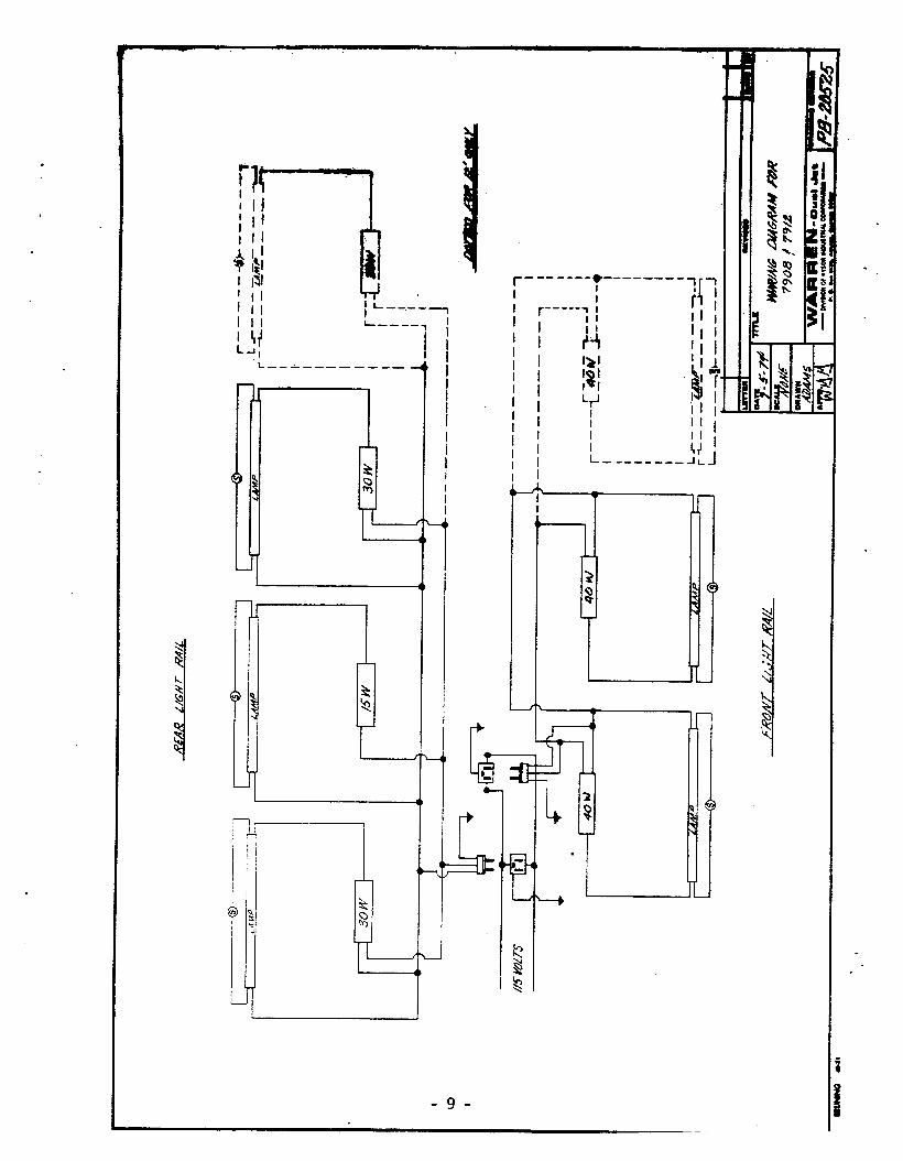
D. Wiring Diagram 4'
E. Compressor Chart
-2-

I 0 Planning for your 7900
A. The 7900 was designed as a rear loaded fixture with sliding doors. It is available either self contained or remote, The self-contained version utilizes an air-cooled condensing unit mounted below the foam shell, l/3 hp for 8' and l/2 hp on 12'.
Refrigeration, electrical and waste drip connections must be planned early. There is space mder the foam shell for interconnection of the fixtures. The waste drips may be also interconnected under the foam shell. Best practice is to connect no more than three fixtures together on waste piping. The waste drip should be an "indirect" open type where the con- densate free falls into an open floor drain. In the Appendix there is a floor plan layout of the 7900 giving location of waste drip, electrical and refrigeration connections.
B Compressor Requirements for remote application are listed in the Appendix for various length lineups. The condensing unit may be either a single compressor - Mastermetic - for a lineup of 1 thru 6 fixtures, or a parallel rack of 2 or 4 compressors - Mfnimetic or Multimetic - serving the entire medium temp requirements of the store. The ratings shown are based on a +15 evaporator, 105OF condensing temperature and store ambients of 8O*F and 55% RH, and 90°F/60% RH.
C. Defrost is conventional off cycle defrost. Usual requirement is one defrost per day at 40-60 minutes each or two per day at 30 minutes each.
II a Installation
A. Unloading instructions, CAUTION: The tops of the 7900 cases are not designed for walking on. Serious personal injury could occur plus irreparable damage to the case.
Remove a17 shipping braces carefully and inspect for damage, prefer- ably in the presence of the delivery man. List any damage on the freight bill and have the delivery man sign it. This is for your protection in settling damage claims.
B. Setting the cases requires the following:
2: 1 3 “Johnson - 2" bar” rollers or "dog" pipe
3. Set of socket and box-end wrenches 4. Crowbars 5. Shims 6. 4' Carpenter's Level
These fixtures are 41 inches wide and 53 inches high complete. Measure your doors before arrival ts assure clearance.
-- 3 -

The 7900 is aligned at the factory prior to shipment on an absolutely level roller bed and cases intended to be joined together are marked "case
of lineup " on each end. It is imperattve that these markings be observed.
Start at the left end and set case 1 in place, on shims if required. It is often helpful to sight the floor to make sure that there is not a pitch to the entire floor. Minor variations in height can be shimmed as you go along. Make sure that gasketing is in place for a good air seal. Replace gasketing if destroyed In transit.
Case 2 should be placed adjacent to case 1, and the T-nuts and bolts (marked 0 on Joint Kit List in Appendix) used to draw the cases together. DO NOT USE JUST ONE OR TWO BOLTS TO DRAW CASES TOGETHER! Tighten all bolts approximately the same amount at a time. When the fixtures are still l/2" apart, caulk, with silicone sealant, the entire portion of the fixture in the foam shell area (drain pan) so that when final tightening is accomplished the silicone is squeezed out along the entire metal end frame adjacent to the foam shell.
Next, both cases now joined together should be re-checked for level and shimmed where necessary. Now proceed to case 3.
C. Do not install any joint trim until entire lineup is in place and level.
Joint trim can now be installed as shown on Appendix drawing.
D. Hookup of refrigeration lines can now be started. Sil-fos, silver solder or soft solder can be used. Be sure that all ferrule openings are sealed with urethane foam which can be dispensed from the throw-away cans. Electrical interconnection can be made under the foam shell.
E. One 115~volt circuit must be supplied to the fixture for lights where . remote condensing unit is utilized. For self-contained units 9 a larger 1150 volt circuit is required.
Wire sizes can be selected from the application sheet in the Appendix for remote models. For self-contained cases the wire sizing should be rated to carry the compressor load as specified in Section II-G. ALWAYS GROUND ANY ELECTRICAL FIXTURE!. FOLLOW THE NATIONAL ELECTRIC CODE AND ANY LOCAL CODES.
The waste drip, discussed earlier, can be run using ABS, PVC or galvanized iron pipe, local codes permitting.
F. Startup (after proper evacuation and charging on remote units) consists mainly of determining correct control settings. Following are recommended initial settings:
1 2:
Defrost Time Clock, 1 per day/50 minutes. Thermostat (when used)cut out 30°, cut in 38O.
3 l Pressure Control on Condensing Unit - cut out 18 psig, cut in 25 psig -R-12.
-4-

When an evaporator/pres&e -regulator-(EPR)& used.ewith- the. fixture-; *:the pressure control setting is.-~not'criticai and a thermostat :-need. not be,-used.,+ c .-.-. , . ,.- . ..-' .-.. . . , ..* . . . ..I.. - . . s . .'b _.... ---, : . . . ~ r . . . . /,-.a. ..e,-. CY...., ..* . . .-. ,- '.* -*
Before adjusting the EPd', ':'& '~~xpahsi~~ ..~val~e‘:'~u&t be a&~~~~~d'. ~ . . ,I . . . ~ *. To ...mi~e.
this faster, it is desirable to make sure the EPR is not throttling. This can be checked with gages connected upstream and downstream. If the pressure drop is less than 2 psi, then it can be assumed the EPR is open and you can proceed to adjust the exmnsIon valve. Normal superheat setting is about lo- lZ*F, and the valves, &installed and shipped, should be fairly close to that range already.
After adjusting the expansion va?ve, the EPR will have to be adjusted. Remove the small knurled cap and use a medium sjze straight screwdriver. Most installations require raising the setting by rotating the slot screw inside clockwise. Evaporator pressure should be 18 psig R-12.
G. 7900 Self Contained. The self-contained 7900 uses a Copelaweld "F" line air cooled condensing unit. The condensing unit is located underneath the display area. R-12 is the refrigerant used in this system. The condensing unit may be serviced by sliding out of case. This is done by removing the retaining clamps on back of case and pulling unit out carefully. The 8' model uses a FSAL-0033, which is a 1/3hp, with 8 amps full load and 42 amps locked rotor amps. The 12' model uses a FGAf60058, which is a 1/2hp, with 11.2 amps full load and 51 amps locked rotor.
III l Maintenance
A. Weekly maintenance should consist of removal of she1 ves and wire racks, and thorough in-place cleaning of racks, deck pans, shelves, and drain pan area, using one of the many high-pressure low-water-volume prayers now on the market at costs of less than $200. A detergent such as Tid B may be used, al though a bactericidal commercial cleaning solution is preferred. Practically any water- based cleaning solution may be used PROVIDED it is rinsed off immediately. After cleaning, the above should be vy and replaced. Next, all interior surfaces should be wiped down with a solution of l/2 cup Lysol@or equal) to one gal
&I n of warm water. Don't use detergents on glass surfaces - use only
Bon Am onderful Glass Cleaner (or equal).
On self-contained models the condenser should be vacuumed weekly. Dirty condensers mean high head pressure which means high operating cost and short life!
B. Semiannual maintenance requires thorough cleaning of drain pan with a hose. The upper coil drain ~a n shou-td be cleaned thoroughly with a high-pressure cleaner. The base area should be vacuumed to remove debris and dust.
-59

REF
. N
O.
DESC
RIPT
ION
BALL
AST
15W
(G
E#89
6381
or
ea
ual)
BALL
AST
30W
(G
M70
6 or
eq
ua’l)
’ 1
FRO
NT
PAN
EL
2 CO
LOR
BAN
D
3 O
UTSI
DE
BACK
PA
NEL
4
LOW
ER
BACK
PA
NEL
5
JUNC
TION
BO
X C
OVE
R
6 R
EAR
BA
FFLE
7
DRIP
PA
N
ASSE
MBL
Y a
REC
EPTA
CLE
W
IRIN
G
CO
VER
9
REC
EPTA
CLE
PL
UG
/SW
ITC
H
ASSY
10
BO
TTO
M
COIL
11
LH
O
UTSI
DE
DOO
R AS
SY
12
LH
INSI
DE
DOO
R AS
SY
13 L ;
RH O
UTSI
DE
DOO
R AS
SY
14
RH
INSI
DE
DOO
R AS
SY
15
EXPA
NSI
ON
VA
LVE-
spor
hn
FF-1
/4-C
1/
4x1/
2 16
R-
12
FLU
OR
ESC
ENT
REA
R
BULB
(F
30T8
N)
18
FLU
OR
ESC
ENT
REA
R
BULB
(F
15T8
N)
19
+LU
OR
ESC
ENT
FRO
NT
BULB
(F4
0T12
N)
20
THER
MO
PAN
E BA
SE
TRIM
21
BU
MPE
R T
RIM
22
U
PPER
CO
IL
17
7908
79
12
lOm
u=
1001
0-13
10
010-
12
lOD
lO-1
2 5l
A12-
73
51A1
4-62
51
A17-
33
51A1
4-33
51
B12-
57
5181
4-52
51
812-
58
51B1
4-53
51
W26
-17
51W
26-1
7 54
H28
-111
54
H30
-76
54Sl
O-4
0 54
SlO
-41
54U
22-1
2 54
1122
-12
82E1
3-16
82
E13-
16
86K1
2-17
86
Kl2-
18
90El
l-30
90E1
3-10
90
Ell-3
1 90
E13-
11
90El
l-32
90E1
3-12
90
Elb3
3 90
E13-
13
3AlO
-34
3AlO
-34
lOAl
O-1
7 lO
AlO
-18
lOAl
O-2
2 15
311-
10
1551
1-16
5A
lo-a
a
lOAl
O-1
7 lO
AlO
-18
lOAl
O-2
2 15
311-
12
1531
1-18
SA
lO-a
9
7908
SC
lfimTt
m3
10D
lO-1
2-
SlA1
2-73
51
A17-
33
5!iB
l a-
52
51B1
2-62
51
W26
-17
54H
28-1
11
54Sl
O-4
0 54
1122
-12
82E1
3-16
86
K12-
17
90El
b30
90El
l-31
90El
l-32
9OEl
b33
3AlO
-34
lOAl
O-1
7 lO
AlO
-18
lOAl
O-2
2 15
311-
10
1531
1-16
SA
lO-8
8
7912
sc
1-3
1001
0-12
51
814-
62
51Al
4-33
51
B14-
52
5189
4-57
51
W26
-17
54H
30-7
6 54
SlO
-41
5411
22-1
2 .
82E1
3-16
86
K12-
18
90E1
3-10
90
E13-
11
90E1
3-12
90
El3-
13
3AlO
-34
lOAl
O-1
7 lO
AlO
-18
80Al
O-2
2 15
Jll-1
2 15
311-
18
SAlO
-a9

, \
, .
, -0
9

JOINT KIT N@-@&Fl3rw FOR MODELS. 7@01- 7912
3.
4.
VINYL KIT .-
5.
6.
7.
0.
9.
10.
11.
12.
FOR SIMPLIFICATION, PLACE FIXTURES AS NEAR THEIR PERMANENT LOCATION AS POSSIBLE BEPORE ReMOVlN6 SKID6 OR ROLURS.
THE LEVEZJNQ OF FIXTURES XS VERY IMPORTANT. ~LEDPERSONNKL A&DAN ACCURATELEVELMUST BE USED. WOODBtyEDoES AREFUFWISHED TO ASSIST IN THIS OPERATION. * .
AN AMPLE SUPPLY OF l/4" ROUND SEALING COMPOU?JD IS SENTUITH EACH MULTIPLE INSTALLATION FOR SWING OFF ANY AIR LEAMOB. IT ISESSENTIALTHAT ALLAIR LEAKSBESEALEDlXORD~TOPREVENT OPERATPJGDZFFICULTIES. REMOVE ANY EXCESS SEALINOCOMPO'UblDWI!l'HA SOLVIGNT SUCH AS MINERAL SPIRX!!!S. SEAL ENTIRE END FRAME AREA WITH GASKET MATERIAL PROVIDED. PIXTURES ARE TO BE PLACEL- END TO END AS CLOSELY AND AS NEAR IN LINE AS POSSIBLE. PLACE T-NUTS IN PREDRILLED HGLES LOCATED ON TOP END FRAME CROSS MEMBER AND Ofi BOTTOM END FRAU CROSS MEMBER. ROTATE 3/8" 4 BOLTS WITH T-NUT WASHERS INTO T-NUTS ALTER- NATELY UNTIL JOINT XS COMPLETELY SEALED. POSITION TRIM AS SHOWN, USING PARTS LIST I DRAWING LETTERS AS A GUIDE.
rrC't REAR JOINT TRIM LOWER. POSITION ON S m' Sf8?'d&TH (-4) #0X5/8 SHEET
CASk'
METAL SCREWS, LEAVING THE TWC SLOTS OPEN. I
'B" REAR JOINT TRIM UPPER. FCSXTICI!! Z: %Sf s m A-G TJfE BCTTO!'? PAIF CF
HOLES WITH SLOTS IN PAF!T '7'. SECURE WI? (4) #8x5/8 SHEIET METAL SCREWS, LEAVr?i~ ~:lf= TWO SLOTS OPEN.
.i !
"H" FRONT GLASS JOINT TRIM. POSITIOK I.": CF.:;-, AND aAL W"TR l/4" BEAD SEXEF
(29810-17). PUSH FIN& TO INSVRE SEAL.
WA' TOP PANEL JOINT TRIK FOSITXON OF: C:?:'E L1GPJf-M THE BCTTObl PATF? FF-
SHEET METAL SCREW& SEC!'R:~ WITH (8) @X5/e
"E" FRONT PAMEL JOfWi' TRIM; POSITION ON CASE. S-H (br #8X5/8 SHEET METAI '.
"D" KICKPLATE JOINT TRIM. PLACE AS SHOWN ANt E4T METAL SCREWS.
"Ptt COLORBAND NOSE PIECE. PLACE NOSE 3ITCE SECURE WITii (2) .
"G" iJOINT TRIM CASTING. POSITiOtJ CASTING Bm lib!D tCASTEbT W1T'H (2)
#8-32X1/2 MACHXNE SCREW FH SIT ST.
13. "3" JOLNT TRfM CHANNEL. POSITION JOIX.: LK CRANNELGE OF END FRAME.
-80
I Lo I
I I L
I. I I I I

r ---a
-

.C
l
:ASf
S 8/
12
I itT
01
1
-8
12
24
28
32
36
40
44
48
52
5Q
60
.~J~~
Jf-)---
-I------
-----I--
--------
-
go01
95
O1
75O
l L
t s
I L
I s
-+-&
Th-I7
78-l-
+l'fi8
70
1 70
1 70
13/8
17
/8
13/B
17
/R
loot
10
01
1001
3/R
17/8
13
/R
170
loot
15
01
1001
3/8
17/Q
13
18
17/O
1501
15
01
1501
3/9
l7/8
Iv
8 17
/f?
1501
ls
ot
lc;o
t3/8
(7
/P
tl/?
lb118
20’0
) zo
ol so
ot3/
8 11
01/8
t11?
I l-
118
2oot
zo
ot
2oot
u2
11-1
/8tl/
2 la-
118
2001
30
01
2001
1/2
ll--l/
flt1/
2 IL
-l/8
3001
30
01
2001
112
11-l/
811/
2 11
-l/8
3901
30
01
39O
W2
11-l/
811/
2 l1-
118
3001
30
01
3Or)t
1/2
11-l/
811/
2 11
-3/F
)
3oot
30
01
joon
/ tl-
a/8t
1/2
t&=3
/8
,300
I 5o
ot
jOOH
/ lb
-1/8
t5/8
IL
-3/8
‘jOOl
50
01
3OOl
V2
(l-l/8
t5/8
(l-
318
'joot
',0
9l
r,Ol)l
J./:!
t a
-3/8
15/2
t l
-3/8
5oot
5O
Ol
5ool1
/2
lli-3/
8(5/
8 t1
-3/8
ym
W
II ym
',/~
tl-3/
815/
8 la
-3/9
5OO
l 5o
ot
5001
6,/8
t1
-3/8
15/8
ll-
3/R
fjrxq
5a
o1
c,I)o
pj;s
ll-
3/8l
TIfI
IX-3
18
fiodl
5s
ot
5OO
l5/0
Il-
3/81
5/fI
t1-3
/fl
55ot
55
01
5001
5/8
ll-3/
815/
Q
D-m
a 1.
c0
M.L
UNlt
REC~
NDAT
JWS
BASE
D %
a W
!lo
Q
F 6
55%
RH
ST
ORE
AMBJ
EHT.
zb
’ 2.
SAHC
AIR
COOL
ED)
UtJlT
SE
LECT
ION
IS
3 BA
SED
WJ
AIR
TE
:HPE
RAYU
RE
ENTE
RING
8
COOB
AS
sH
@w.
SW
(W
ATER
fi 4
mob
LIt)
war
sELE
CtloN
M
SED
ON
3 2
Gf’M
tO
tJ-‘l
~”
f W
ATER
EN
TERI
NG.
. 30
COO
. W
IT
SUF:
pJX
IS:
iF
RL-L
W
TEW
R-
502
’ ,
rm5t
F5f
lmr
SAli
. *‘-
’ NH
i
STZT
NSC
R+
d?
O-7
5 I
75-1
50'
mA)
4fjIE
tJf-,
~~
~~~~
oloo-
o---)
--~~"
--~~~
~ r)f
Pl
05O
l 75
01
L Cl
I
I s
I L
1 s
t I
t -1
'1
-l3
/Rlm
mm
-l7/R
t
I 13
/a
170
1318
l7
/8
I I
1318
1~
8 13
18
17/r!
I
I 13
18
1718
w2
17
/o
I t
I-3/S
l7
/8
I1/2
17
/8
I t
11/2
17
/R
IV2
l?M
t t
t1/2
17
/a
lx?
11-m
t
I ta
n 17
18
l1/2
11
-w!
I I
t1/2
ll-
1/8l
1/2
11-m
I
I j1
/2
ll-uR
t1/2
11
-m
. I I
1112
II-
1181
112
Ibh/
R
I I
1112
n-
1/81
5/8
I1-1
/R
3101
31
~1
3mta
/2
lbn/8
15/8
lb-
-l/~
3181
31
01
31r)t
1/2
tl-m
m/~
t1
-3/a
3101
31
Of
3111
t1,‘2
tl-
l/815
/8
11-3
/B
4’c)l
4431
3'
?1';/
8 ll-1
/Rt5
/8
ll-3/R
4101
4:r
)t vo
tc,/R
n-
n/81
5/8
n-3/
8 41
0)
41nt
‘m
l5/R
lb
l/Rl5
/8
Il-3M
wq
=lrl(
W
)tr,/8
t1
-3/8
15/8
11
-3/fl
51
01
j101
wqs/a
11
93/8
15/8
11
-3/a
510)
51
01
51ot
5/8
t1-3
/8wf
l 1%
-3/u
51
ot
5101
51
015/
8 t1
-3;V
5/8
1103
/u
t t
t I
1 .
. I
1141
15.2
112
l111
16.6
l12
1iwu
I.011
2 llb
l19J
l12
4.
CAUT
ION:
TH
EM
R~CO
WEN
I)AT
I OtJS
T)
ASEn
ON
RE
ST
JtJFO
RHAT
~OtJ
AVAI
LARL
E AN
0 Ot
I CO
NDIT
IONS
AS
LI
STED
FO
R AP
PLIC
ATJW
S M
IT
LJST
FD
CWSU
LT
WC1
tJE
ERJN
G DW
ARfM
!NT.
50
L
I tlE
LE
tJGTH
S SH
CMtl
ARE
Er)U
J VA
LEtJ
T LE
NGTH
S.
Tr,
DETE
RMIN
P,
EqU
t VM
ENT
LEtJG
TH
HEAS
URE
ACTU
AL
CJNE
AL
LEW
VH
FROM
CO
MPR
ESSO
R TO
FU
RTHE
ST
CASE
6.
RISE
R AH
O P-
YRAP
S SH
WLD
: RE
- DU
CEP
OtJE
SJ
ZE
FMM4
TH
AI
SHm
7.
W
IRE
SIZE
S AR
E BA
SED
OH
100’
OF
TYPE
‘I
m
TU.
8.
LIGH
TS:
lvIIs
wo)Iw
AR
E FQ
R ST
AtJD
ARD
FI
XWES
. FO
U EA
CH
LIGH
TED
WEl
.F
ADD
0.7
A)tQ
. 0 e
0 TH
REE
WAS
E AM
PS
xs
HAxw
Ucl
FOR
WE
LEG.
-
RC+O
TE
MP
R-50
2 NJ
0 AD
D FO
UR
FEET
FO
R EA
CH
ELRW
10
. W
ASTE
O
UfLF
T IS
ST
ANDA
RD
ec-0
TE
MP
R-12
OR
OT
HER
FITT
ING.
1
JNCd
)4
.P.T
. up
to
30
7990
sto
rt
C(UJ
NtCl
1 Ot
JS
: 79
00
SUCt
IOtJ
LINE
j/2
’ 00
, Llf
?UID
LI
NE
I/rm
00
ZTS
SUCT
ION
LINE
5/
8"
00,
LIQ
USD
LfW
L 31
8"
od
u A
@
R L
N /
S H
E R
E u
cam
f9Sf
NG
WJJ
T RE
CMUE
NOAT
tOt~
,
RRFR
tW@
&W
l.tNt:
SIZI
NG
l EL
ECTR
JW
DATA
FM
:
# to
go
0
Ston
E ,
strc
trtu4
TC
M?r
!UA
T~E
l 15
’V