Instructions-For-Use (IFU) & Information Guide · PDF fileDo not wear VitalConnect Sensor,...
20
IFU-01, Rev. A Page 1 of 20 Instructions-For-Use (IFU) & Information Guide IFU-01
Transcript of Instructions-For-Use (IFU) & Information Guide · PDF fileDo not wear VitalConnect Sensor,...

IFU-01, Rev. A Page 1 of 20
Instructions-For-Use (IFU)
& Information Guide IFU-01

IFU-01, Rev. A Page 2 of 20
Instructions For Use (IFU) & Information Guide
This document provides instructions and information for the VitalConnect Platform, also referred as
Wireless physiological monitoring system. VitalConnect platform is developed as an Application
Programming Interface (API), intended to be used as a programming platform to allow mobile health care
services providers to develop user interface applications enabling the users (i.e. physician, caregiver,
patients) to view and/or access collected vital information. The platform consists of:
1. VitalConnect Sensor
2. VitalConnect Relay Software Library
3. VitalConnect Secure Server Software Library
User Assistance information
For additional information regarding the proper use of the VitaConnect Platform and mobile service
provider user interface, please contact the prescribing physician, caregiver, or health care provider.
Device Description
The VitalConnect Platform consists of the VitalConnect Sensor, Relay Software Library, and Server
Software Library. The VitalConnect Platform is accessible via an application program interface (API) that
allows authorized persons to receive data and notifications generated by the system.
The VitalConnect Sensor is a battery-operated adhesive patch with integrated sensors and wireless
transceiver, worn on the torso to record heart rate, electrocardiography (ECG), heart rate variability,
respiratory rate, skin temperature, fall detection, step count and posture. The sensor continuously gathers
physiologic data and then transmits the data via a Relay Software Library managed bi-directional relay
device to a central server controlled by the Server Software Library, where the data is stored for analysis
by healthcare professionals and researchers.
Authorized healthcare professionals can configure the system parameters via the API to generate
notification of changes in measured data. A notification is triggered when configured physiologic data
parameters are exceeded. Notification can be transmitted to a generic display device (i.e. smartphone,
tablet, PC or monitor).
VitalConnect Platform sub-systems include:
1. VitalConnect Sensor
a) Patch
The Patch is designed as a low cost disposable self-adhesive interface to the body.
b) Sensor Module
Residing within the patch, the sensor module performs processing functions related to capture of
physiologic data and also performs bi-directional communication with the relay device.

IFU-01, Rev. A Page 3 of 20
2. VitalConnect Relay Software Library The Relay Software Library manages bi-directional communication between the Sensor Module and
the Server Software Library and is installed on a relay device.
3. VitalConnect Server Software Library The Server Software Library is installed on a central server, manages the upload, processing and
storage of sensor data, as well as real-time configuration of and notifications from the VitalConnect
Platform.
Antenna Description
The VitalConnect Sensor Module utilizes a Fractus Micro Reach Xtend 2.4GHz Chip Antenna (part #FR05-
S1-N-0-110) in order to communicate via Bluetooth low energy to the relay. This antenna is a linear,
omnidirectional, monopole antenna that operates in the 2.4-2.5GHz range. The antenna is connected to
the Bluetooth transceiver through a 2 inductor matching network that has been optimized to maximize the
power radiated by the antenna and minimize the voltage standing wave ratio (VSWR). The product is for
use with BT 4.0 only.
Indications for Use
The VitalConnect Platform is a wireless monitoring system intended for use by healthcare professionals and researchers for unattended surveillance of patient physiologic data. This includes heart rate, electrocardiography (ECG), heart rate variability, respiratory rate, skin temperature, fall detection, step count and posture. Data is transmitted wirelessly to a central location where it is stored for analysis. The VitalConnect Platform can be configured by Authorized Persons to notify healthcare professionals when physiologic data falls outside selected parameters.
The VitalConnect Platform is intended for use on general care patients which are at least 18 years of age. It is not intended for use on critical care in-patients. It is not intended as a diagnostic or alarm device.

IFU-01, Rev. A Page 4 of 20
Information Guide:
General Warnings and Precautions:
Warning:
No modification to the VitalConnect Sensor is permitted.
No modification to the relay is permitted.
Do not wear VitalConnect Sensor if you are under the age of 18.
Do not wear VitalConnect Sensor, without the consent of your healthcare provider, if you have implanted defibrillators.
Do not wear VitalConnect Sensor, without the consent of your healthcare provider, if you have implanted pace-makers.
Do not wear VitalConnect Sensor if you are Pregnant or breastfeeding
If you are wearing a VitalConnect Sensor and plan on traveling on an airplane, contact your service provider for instruction.
All components of VitalConnect Sensor should be kept out of the reach of children, pets, or anyone who may swallow components or otherwise be at risk of being harmed by components. If any component is swallowed, seek emergency medical attention immediately.
Do not share your patch or sensor components with others to avoid damage to your device, potential harm to others, and/ or risk of contamination.
Do not use a patch if the container has been opened or appears to have been used or damaged.
Do not make any modifications to any components of the VitalConnect System, unless otherwise instructed by Vital Connect Inc. and its approved affiliates.
If connected to other devices/system through the same user interface (i.e. mobile phone), while connected to the VitalConnect System via a Bluetooth connection, please note that performance of either or both Bluetooth connected devices/system could potentially be affected.

IFU-01, Rev. A Page 5 of 20
Caution:
Do not wear a “previously used” patch beyond its recommended life cycle of three (3) days.
You may experience slight discomfort and/or itchiness as a result of wearing silicone or acrylic adhesive materials. If you experience discomfort or irritation, beyond mildly tolerated symptoms, please remove patch immediately.
It is possible to experience mild soreness and/or redness after the removal of a patch. If you experience this affect, do not wear the patch in the same area.
Adverse skin reactions may occur due to the nature of this product containing silicone or acrylic adhesives. Should event of adverse or allergic reactions occur and persist beyond two to three (2-3) days, contact your healthcare provider for further consultation.
Do not wear patch and module while swimming.
Protect the silicone adhesive patch and sensor module units from excessive moisture and/or sweating to avoid product malfunction and lack of proper adhesion.
Module and patch will not be damaged while showering or bathing if properly sealed. Do not submerge in more than 18 inches of water.
Patient / end user physiological signal values shall be set within the allowable configured minimum and maximum range.
Connectivity and data transmission of device may be interrupted while under water. Reconnect your device once you are out of the water after allowing for drying time.
Handle the VitalConnect System with care and according to instruction of use.
Incorrect handling, use of excessive force, or dropping of any components of the VitalConnect System may cause malfunction and/or permanent damage to the patch and sensor module.
Keep VitalConnect Sensor components away from excessive heat exposure, as this may cause damage.
To ensure optimal performance of the VitalConnect System, avoid wearing the VitalConnect Sensor while undergoing any medical imaging procedures such as MRI, CT, X-ray, PET, etc.
If any component of your VitalConnect System fails to operate after attempting all suggested troubleshooting methods, contact your product provider immediately.
Do not dispose the patch and battery in a household trash bin. Dispose per local laws, care facility laws or hospital laws.
If the patch or sensor module becomes un-responsive and unable to link, remove the module from the patch and replace it in a new patch. If it is still un-responsive and unable to link, replace the module. User will be notified of the failure via a text message on the relay (i.e. phone).
When traveling in a car, vital data collected by the sensor module may not be transmitted to the server, due to the unavailability of Bluetooth (the amount of data collected by the module is depends on the sensor module memory size).
When traveling on an airplane, vital data collected by the sensor module will not be transmitted to the server, due to the unavailability of Bluetooth (the amount of data collected by the module is depends on the sensor module memory size).

IFU-01, Rev. A Page 6 of 20
General Information:
VitalConnect Sensor is tested by UL for electrical safety in accordance with IEC 60601-1-1
VitalConnect Sensor is tested by UL for electromagnetic compatibility in accordance with IEC 60601-1-2
Vital Connect Sensor complies with the Essential Performance defined in 60601-1, amendment 1: “performance of a clinical function, other than that related to BASIC SAFETY, where loss or degradation beyond the limits specified by the MANUFACTURER results in an unacceptable RISK”, either with applicable testing or via user documentation.
VitalConnect system is tested by UL for FCC in accordance with ANSI C63.10-2009, FCC CFR 47 Part 2, FCC CFR 47 Part 15, RSS-GEN Issue 3, and RSS-210 Issue 8.
Electronic components are RoHS compliant.
Patch top layer and adhesive is medical grade.
Software failure, firmware failure or battery failure has no adverse effect on the end-user. The failure would vital data collection and transmission. In the event this occurs, the end-user or service provider will be notified as applicable.
VitalConnect Sensor is: o Type BF applied part o Not reusable o IPX4, protected against water spray o IPX7, protected against water submersion
No installation or maintenance is required.
The patch is intended for a one-time use, for up to 3 days.
The battery is not rechargeable. It’s intended for a one-time use for the life of the patch which is up to 3 days.
The system does not display any messages
Start-up process is not included in this manual. This IFU is not intended for the end-user.
Shutdown procedure is not included in this manual. This IFU is not intended for the end-user.
No cable or physical connection required. The only connection is the Sensor Module to the Patch (as shown in General Description below.
Vital Connect Sensor should not be used adjacent to or stacked with other equipment and that if adjacent or stacked use is necessary, Vital Connect Sensor should be observed to verify normal operation in the configuration in which it will be used.
Packaging label is legible within 90 degree viewing angle of the label.
Packaging label is legible within distance of 50 cm (20 inches)
Packaging label is legible within 500 lux – 1000 lux lighting (i.e. foot-candles)
IFU-01, Rev. A Page 7 of 20
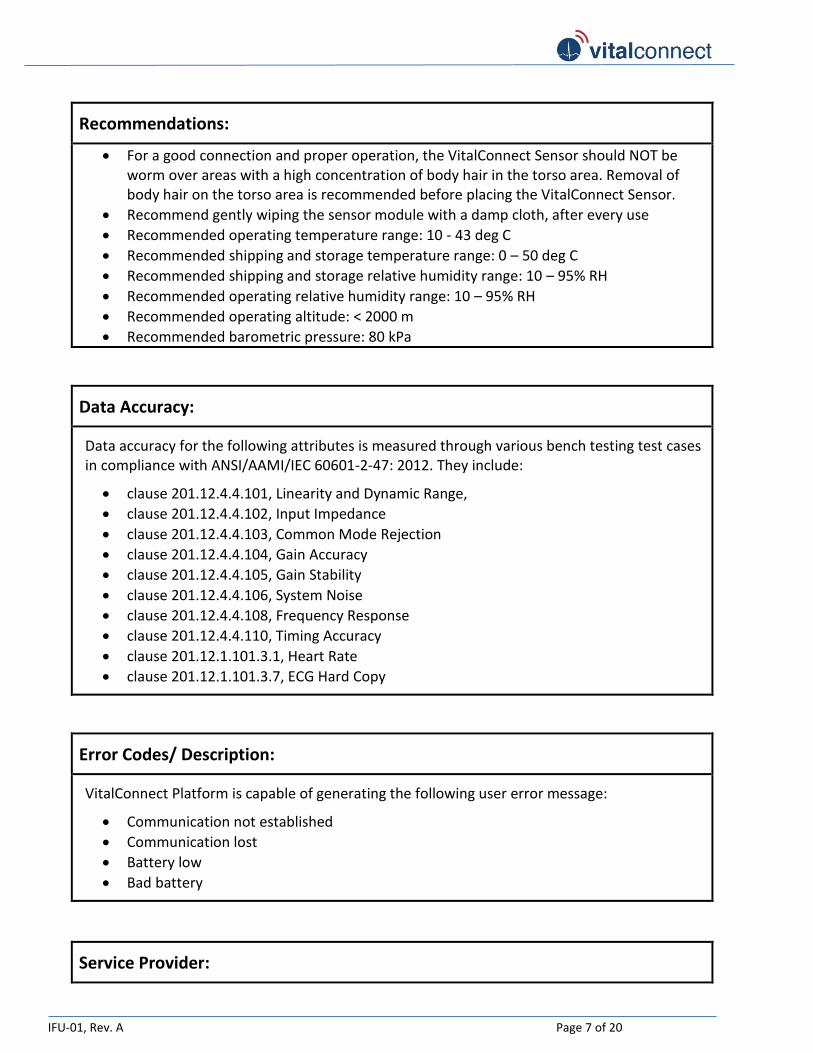
Recommendations:
For a good connection and proper operation, the VitalConnect Sensor should NOT be worm over areas with a high concentration of body hair in the torso area. Removal of body hair on the torso area is recommended before placing the VitalConnect Sensor.
Recommend gently wiping the sensor module with a damp cloth, after every use
Recommended operating temperature range: 10 - 43 deg C
Recommended shipping and storage temperature range: 0 – 50 deg C
Recommended shipping and storage relative humidity range: 10 – 95% RH
Recommended operating relative humidity range: 10 – 95% RH
Recommended operating altitude: < 2000 m
Recommended barometric pressure: 80 kPa
Data Accuracy:
Data accuracy for the following attributes is measured through various bench testing test cases in compliance with ANSI/AAMI/IEC 60601-2-47: 2012. They include:
clause 201.12.4.4.101, Linearity and Dynamic Range,
clause 201.12.4.4.102, Input Impedance
clause 201.12.4.4.103, Common Mode Rejection
clause 201.12.4.4.104, Gain Accuracy
clause 201.12.4.4.105, Gain Stability
clause 201.12.4.4.106, System Noise
clause 201.12.4.4.108, Frequency Response
clause 201.12.4.4.110, Timing Accuracy
clause 201.12.1.101.3.1, Heart Rate
clause 201.12.1.101.3.7, ECG Hard Copy
Error Codes/ Description:
VitalConnect Platform is capable of generating the following user error message:
Communication not established
Communication lost
Battery low
Bad battery
Service Provider:

IFU-01, Rev. A Page 8 of 20
In the event the Internet is interrupted, Service Provider should notify the end-user (patient) that patient vital data is not being transmitted.
Provide detail use instruction and information on the user interface application.
FCC:
FCC ID : SPO-VCI-Module
IC: 11013A-VCIMODULE
This device complies with part 15 of the FCC Rules. Operation is subject to the following two conditions: (1) This device may not cause harmful interference, and (2) this device must accept any interference received, including interference that may cause undesired operation (FCC Title 47, Subpart A, Part 15.19(3)).
Changes or modifications not expressly approved by the party responsible for compliance could void the user’s authority to operate the equipment (FCC Title 47, Subpart A, Part 15.21)
Note: This equipment has been tested and found to comply with the limits for a Class B digital device, pursuant to part 15 of the FCC Rules. These limits are designed to provide reasonable protection against harmful interference in a residential installation. This equipment generates uses and can radiate radio frequency energy and, if not installed and used in accordance with the instructions, may cause harmful interference to radio communications. However, there is no guarantee that interference will not occur in a particular installation. If this equipment does cause harmful interference to radio or television reception, which can be determined by turning the equipment off and on, the user is encouraged to try to correct the interference by one or more of the following measures (FCC Title 47, Subpart B, Part 15.105(b)):
o Reorient or relocate the receiving antenna. o Increase the separation between the equipment and receiver. o Connect the equipment into an outlet on a circuit different from that to which the
receiver is connected. o Consult the dealer or an experienced radio/TV technician for help.

IFU-01, Rev. A Page 9 of 20
Electromagnetic Compatibility (EMC):
Vital Connect Sensor may need special precautions regarding EMC and should be used according to the EMC information provided in the “Warning” and “Caution” sections of this document.
Portable and mobile RF communications equipment can affect Vital Connect Sensor. See Medical Electrical Equipment user manual for RF communication precautions.
Type of radio modulation, frequency and antenna power is follows:
o Radio modulation: FSK (frequency shift keying)
o Frequency: 2.4 – 2.5GHz
o Antenna power: 4dbm.
Electromagnetic Emission Declaration
Vital Connect Sensor (i.e. patch model #: 545-00006-00 and module model #: 600-0001-00) is intended for use in the electromagnetic environment specified below. The patient or the end user of the Vital Connect Sensor should assure that it is used in such an environment.
Emission test Compliance Electromagnetic environment
RF emissions CISPR 11 Group 1 Vital Connect Sensor uses RF energy only for its internal function. Therefore, its RF emissions are very low and are not likely to cause any interference in nearby electronic equipment.
RF emissions CISPR 11 Class B Vital Connect Sensor is suitable for use in all establishments, including domestic establishments and those directly connected to the public low-voltage power supply network that supplies buildings used for domestic purposes.

IFU-01, Rev. A Page 10 of 20
Guidance and declaration – electromagnetic immunity (For ME equipment ME system that are not life-supporting)
Vital Connect Sensor is intended for use in the electromagnetic environment specified below. The end user of the Vital Connect Platform (including Vital Connect Sensor) should assure that it is used in such an environment.
Immunity test
IEC 60601 test level
Compliance level
Electromagnetic environment- guidance
Radiated RF
IEC 61000-4-3
3 V/m
80 MHz to 2.5 GHz
3 V/m Portable and mobile RF communications equipment should be used no closer to any part of the Vital Connect Platform than the recommended separation distance calculated from the equation applicable to the frequency of the transmitter.
Recommended separation distance
d = 1.81 80 MHz to 800 MHz
d= 3.69 800MHz to 2.5 GHz
where P is the maximum output power rating of the transmitter in watts (W) according to the transmitter manufacturer and d is the recommended separation distance in meters (m).
Field strengths from fixed RF transmitters, as determined by an electromagnetic site survey, a
should be less than the compliance level in each frequency range b.
Interference may occur in the vicinity of equipment marked with the following symbol:
NOTE 1 At 80 MHz and 800 MHz, the higher frequency range applies.
NOTE 2 These guidelines may not apply in all situations. Electromagnetic propagation is affected by absorption and reflection from structures, objects, and people. a Field strengths from fixed transmitters, such as base stations for radio (cellular/cordless) telephones and land mobile radios, amateur radio, AM and FM radio broadcast and TV broadcast cannot be predicted theoretically with accuracy. To assess the electromagnetic environment due to fixed RF transmitters, an electromagnetic site survey should be considered. If the measured field strength in the location in which Vital Connect Platform is used exceeds the applicable RF compliance level above, the Vital Connect Platform should be observed to verify normal operation. If abnormal performance is observed, additional measures may be necessary, such as re-orienting or relocating the Vital Connect Platform.
b Over the frequency range 150 kHz to 80 MHz, field strengths should be less than 3 V/m.

IFU-01, Rev. A Page 11 of 20
Guidance and declaration – electromagnetic immunity (For ME equipment ME system that are not life-supporting)
Vital Connect Sensor is intended for use in the electromagnetic environment specified below. The end user of the Vital Connect Platform (including Vital Connect Sensor) should assure that it is used in such an environment.
Immunity test IEC 60601 test level
Compliance level
Electromagnetic environment- guidance
Electrostatic discharge (ESD)
IEC 61000-4-2
± 6 kV contact
± 8 kV air
± 6 kV contact
± 8 kV air
Floors should be wood, concrete, or ceramic tile. If floors are covered with synthetic material, the relative humidity should be at least 30 %.
Power frequency (50/60 Hz) magnetic field
IEC 61000-4-8
3 A/m 0.3 A/m Power frequency magnetic fields should be at levels characteristic of a typical location in a typical commercial or hospital environment.
NOTE: UT is the a.c. mains voltage prior to application of the test level.

IFU-01, Rev. A Page 12 of 20
Recommended separation distance between portable and mobile RF communications equipment and Vital Connect Platform
(For ME equipment ME system that are not life-supporting)
Vital Connect Sensor is intended for use in the electromagnetic environment in which radiated RF disturbances are controlled. The end user of the Vital Connect Platform (including Vital Connect Sensor) can help prevent electromagnetic interference by maintaining a minimum distance between portable and mobile RF communications equipment (transmitters) and the Vital Connect Platform Sensor as recommended below, according to the maximum output power of the communications equipment.
Rated maximum output power of
transmitter W
Separation distance according to frequency of transmitter m
80 kHz to 800 MHz 800 kHz to 2.5 GHz
0.01 0.17 0.23
0.1 0.37 0.74
1 1.17 2.33
10 3.69 7.38
100 11.67 23.33
For transmitters rated at a maximum output power not listed above, the recommended separation distance d in meters (m) can be estimated using the equation applicable to the frequency of the transmitter, where P is the maximum output power rating of the transmitter in watts (W) according to the transmitter manufacturer.
Note 1: At 80 MHz and 800 MHz, the separation distance for the higher frequency range applies. Note 2: These guidelines may not apply in all situations. Electromagnetic propagation is affected by absorption and reflection from structures, objects, and people

IFU-01, Rev. A Page 13 of 20
The following marking information will be placed on the package:
Description:
VitalConnect Sensor Patch, (Patch Model No.: 545-00006-00, Sensor Model No.: 600-00001-00) CAUTION:
- Do not place device on broken skin. If irritation develops, discontinue use
- For individual use only - Do not use if package has been
opened - Do not use if you have an
implanted device such as a pacemaker
For detail information, see Instructions for use
Manufactured by: Vital Connect, Inc. 2105 S. Bascom Ave Campbell, CA 95008 408-963-4600
www.vitalconnect.com
IP24
IP27
Underwriters Laboratories
MEDICAL — PATIENT MONITORING EQUIPMENT AS TO ELECTRICAL SHOCK, FIRE AND MECHANICAL HAZARDS ONLY
IN ACCORDANCE WITH
ANSI/AAMI ES60601-1 (2005), "Medical Electrical Equipment - Part 1: General Requirements for Basic Safety and Essential Performance;
CAN/CSA-C22.2 No. 60601-1:08; ANSI/AAMI/IEC 60601-2-25,
"Medical Electrical Equipment - Part 2-25: Particular Requirements for the Basic Safety and Essential Performance of Electrocardiographs" E358758
Recommended shipping and storage temperature range: 0 – 50 deg C Recommended shipping and storage relative humidity range: 10 – 95% RH

IFU-01, Rev. A Page 14 of 20
VitalConnect Platform
VitalConnect platform consists of the following sub-systems:
1. VitalConnect Sensor
2. VitalConnect Relay Software Library
3. VitalConnect Secure Server Software
Instruction for use for the Mobile Healthcare Service Provider
1. VitalConnect Secure Server Software Library
a) Download Software
1) Goto www.vitalconnect.com
2) Select Download
3) Select Server Software
4) Select Media (location to download the software application)
5) Login using Vital Connect provided user ID, and user assigned password
6) Select “Start Download”
b) Ensure that applicable software tools, drivers, etc. have been properly installed to allow
communication between the “server software library”, “service provider user interface
application” and the “relay software library”.
c) Configure user parameters as required (relay software library and server library).
d) Prepare and provide user with additional user instruction as applicable.
2. Ensure that VitalConnect Relay intended to collect end user vital data is functional.
Instruction for use for the end-user
1. Unpack the relay module and plug into a 110-120Vac outlet.
2. Confirm that the green LED light is “on” on the module.
3. Follow VitalConnect Sensor assembly and use instruction below.

IFU-01, Rev. A Page 15 of 20
Start-up process:
Note: this process only applies to the end user.
1. Unpack the VitalConnect Sensor box.
2. Follow the assembly instruction provided in the VitalConnect Sensor box.
3. If the VitalConnect Sensor is assembled and placed on the torso per the IFU, physiologic data
should be automatically collected and transmitted to the server designated by the Service Provider.
Shut-down process:
1. Remove VitalConnect Sensor from torso.
2. Remove sensor module (see IFU).
3. Physiologic data collection and transmission will stop.
4. To use a new patch, follow steps 2 and 3 of the “Start-up process”.

IFU-01, Rev. A Page 16 of 20
VitalConnect Sensor - Assembly Instruction (bottom entry):
Sensor Module
Patch
Module
Connector
Figure 1: Front logo side Figure 2: Back side
Connector Tongue (2) Module compartment/ cavity (3)
Figure 5: Inside patch
Paper Liner of Back Flap (5)
2
5
1
3
Figure 4: Adhesive Side
Back Flap (1)
Clear Release Liner (6)
1
6
* Crescent shaped tab located at the
edge is designed to help you grip and
move the flap.
Figure 3: Front of patch
* Battery side
* Module side
* Blue outline shown on Figure-3 below is for visualization and may not be indicated on the patch
Wing side
4 Module cavity adhesive rim (4)

IFU-01, Rev. A Page 17 of 20
Figure 1: Lift back flap (1) over to opposite side. Use your finger to hold back flap down.
Figure 2: Insert module into connector tongue (2). Push module pass a slight resistance until it can no longer move inward. (Green LED light will blink with functioning module and patch)
2
Figure 3: Press module into cavity (3).
1
3
Figure 4: Peel paper liner (5) off back flap (1). Fold back flap (1) onto module cavity adhesive rim (4) lining up the edges as much as possible.
Figure 5: Press down firmly on the edge of back
flap (1) to ensure it is sealed.
Figure 6: Separate patch from clear release liner
by carefully peeling off clear liner (6). Start from
left (battery side) to right (module side).
LEFT RIGHT
1
Please read before use:
1. Please ensure hand is clean, dry, and non- greasy before handling patch and sensor. 2. It is recommended for men with long chest hair to trim or shave at least several hours before
application. 3. It is recommended that you stand or sit upright and use a mirror when applying patch to chest.
1
5 4
Peel paper liner (5)
Back Flap (1)
Adhesive
flap (4)
5

IFU-01, Rev. A Page 18 of 20
Removing Module from Patch
Figure 11: Remove any patch material that may be stuck to module and pull module from connector tongue.
Figure 10: Pull the wing up while pushing thumb down on module side until sealed cavity is popped open and module is revealed. This hand gesture is similar to “popping” a pill or gum out of a foil packet.
Figure 9: Hold patch securely by the wing side with 1 hand (pulling upward position). With the other hand, place thumb on top edge of the module side.
** To take patch off, lift the edge
off one wing and slowly peel it off
skin.
Position 2
Position 3
Position 1
Figure 8: Please sit upright or stand in front of a mirror to ensure proper placement of patch on your chest. Place patch on the left chest in 1 of 3 recommended positions:
1. Upper chest at 45 degree angle pointing towards the center
2. Center of chest at the sternum
3. Under chest over ribcage pointing to
center of body
Figure 7: Hold patch in one hand with adhesive side facing you.
IFU-01, Rev. A Page 19 of 20
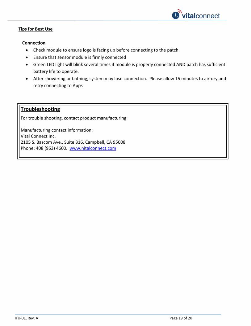
Tips for Best Use
Connection
Check module to ensure logo is facing up before connecting to the patch.
Ensure that sensor module is firmly connected
Green LED light will blink several times if module is properly connected AND patch has sufficient
battery life to operate.
After showering or bathing, system may lose connection. Please allow 15 minutes to air-dry and
retry connecting to Apps
Troubleshooting
For trouble shooting, contact product manufacturing Manufacturing contact information: Vital Connect Inc. 2105 S. Bascom Ave., Suite 316, Campbell, CA 95008 Phone: 408 (963) 4600. www.nitalconnect.com

IFU-01, Rev. A Page 20 of 20
General symbols
Symbol Title
IP24 Protected against splashing water
IP27 Protected against submerging in water (up to 1 meter for 30 minutes)
Do not reuse
Operating instruction
Follow operating instruction
Non-ionizing radiation
Defibrillation proof type CF applied part
Underwriters Laboratories
MEDICAL — PATIENT MONITORING EQUIPMENT AS TO ELECTRICAL SHOCK, FIRE AND MECHANICAL HAZARDS ONLY
IN ACCORDANCE WITH
ANSI/AAMI ES60601-1 (2005), "Medical Electrical Equipment - Part 1: General Requirements for Basic Safety and Essential Performance;
CAN/CSA-C22.2 No. 60601-1:08; ANSI/AAMI/IEC 60601-2-25,
"Medical Electrical Equipment - Part 2-25: Particular Requirements for the Basic Safety and Essential Performance of Electrocardiographs" E358758