Instructions for use ESTETICA E30 - Dental outlet · Instructions for use ESTETICA E30 1 User...
130
Instructions for use ESTETICA E30
Transcript of Instructions for use ESTETICA E30 - Dental outlet · Instructions for use ESTETICA E30 1 User...

Instructions for use
ESTETICA E30

Manufacturer:Kaltenbach & Voigt GmbHBismarckring 39D-88400 Biberachwww.kavo.com
Distributed by:KaVo Dental GmbHBismarckring 39D-88400 BiberachPhone +49 (0) 7351 56-0Fax +49 (0) 7351 56-1488

Table of contents
1 User instructions............................................................................................................................................... 61.1 User guide................................................................................................................................................ 6
1.1.1 Abbreviations............................................................................................................................... 61.1.2 Symbols....................................................................................................................................... 61.1.3 Target group................................................................................................................................ 6
1.2 Service...................................................................................................................................................... 71.3 Terms and conditions of warranty............................................................................................................. 71.4 Transportation and storage....................................................................................................................... 7
1.4.1 Currently valid packaging regulations......................................................................................... 71.4.2 Damage in transit........................................................................................................................ 71.4.3 Information on the packaging: Storage and transportation......................................................... 9
2 Safety............................................................................................................................................................. 102.1 Description of safety instructions............................................................................................................ 10
2.1.1 Warning symbol......................................................................................................................... 102.1.2 Structure.................................................................................................................................... 102.1.3 Description of hazard levels...................................................................................................... 10
2.2 Purpose – Proper use............................................................................................................................. 102.2.1 General...................................................................................................................................... 102.2.2 Product-specific......................................................................................................................... 13
2.3 Safety instructions.................................................................................................................................. 142.3.1 General information................................................................................................................... 142.3.2 Product-specific......................................................................................................................... 15
3 Product description......................................................................................................................................... 183.1 Treatment unit versions.......................................................................................................................... 18
3.1.1 KaVo ESTETICA E30 S............................................................................................................ 183.1.2 KaVo ESTETICA E30 TM.......................................................................................................... 18
3.2 Patient chair............................................................................................................................................ 193.3 Unit with patient element........................................................................................................................ 203.4 Dentist unit versions............................................................................................................................... 21
3.4.1 TM table..................................................................................................................................... 213.4.2 S table....................................................................................................................................... 21
3.5 Assistant unit.......................................................................................................................................... 233.6 Triple-function handpieces...................................................................................................................... 243.7 Controls.................................................................................................................................................. 25
3.7.1 Dentist's unit TM table............................................................................................................... 253.7.2 Dentist's unit S table.................................................................................................................. 253.7.3 Assistant unit............................................................................................................................. 263.7.4 Groups of keys.......................................................................................................................... 263.7.5 Foot control................................................................................................................................ 28
3.8 Rating plate and serial number plates.................................................................................................... 293.9 Technical data........................................................................................................................................ 34
4 Operation........................................................................................................................................................ 394.1 Switching the device on and off.............................................................................................................. 394.2 Converting from right handed to left handed.......................................................................................... 394.3 Adjusting the dental chair....................................................................................................................... 43
4.3.1 Adjusting the armrest (optional)................................................................................................. 43
Instructions for use ESTETICA E30
Table of contents
3 / 130

4.3.2 Adjust head rest......................................................................................................................... 444.3.3 Positioning the dental chair manually........................................................................................ 454.3.4 Automatic positioning of dental chair......................................................................................... 474.3.5 Safety shut-off........................................................................................................................... 50
4.4 Moving the patient chair.......................................................................................................................... 534.5 Moving the dentist unit............................................................................................................................ 53
4.5.1 Moving the dentist unit TM........................................................................................................ 544.5.2 Moving the dentist unit S........................................................................................................... 55
4.6 Moving the patient unit............................................................................................................................ 554.6.1 Moving the patient element (optional)....................................................................................... 56
4.7 Attaching the tray holder (optional)......................................................................................................... 574.8 Using functions through the menu.......................................................................................................... 57
4.8.1 General menu navigation.......................................................................................................... 574.8.2 Using the user menu................................................................................................................. 574.8.3 Standby menu........................................................................................................................... 634.8.4 Selecting the dentist.................................................................................................................. 644.8.5 Instruments menu...................................................................................................................... 644.8.6 ENDO menu (optional).............................................................................................................. 674.8.7 Using the CONEXIOcom (optional)........................................................................................... 72
4.9 Using function through the dentist or assistant unit................................................................................ 744.9.1 Using the hygiene functions...................................................................................................... 744.9.2 Using the illumination functions for KaVoLUX 540 LED T......................................................... 754.9.3 Using the illumination functions for EDI and MAIA.................................................................... 814.9.4 Using the X-ray viewer.............................................................................................................. 814.9.5 Using the bell............................................................................................................................. 814.9.6 Using the timer.......................................................................................................................... 81
4.10 Operating the foot switch........................................................................................................................ 834.10.1 General functions...................................................................................................................... 834.10.2 Positioning the patient chair with the foot control...................................................................... 834.10.3 Preselect dentist........................................................................................................................ 834.10.4 Start and regulate instruments.................................................................................................. 834.10.5 Setting the cooling condition..................................................................................................... 844.10.6 Activating blown air (optional).................................................................................................... 844.10.7 Preselect counterclockwise motor rotation................................................................................ 844.10.8 Adjusting the instrument light.................................................................................................... 844.10.9 Using CONEXIOcom (fee-based additional option).................................................................. 85
4.11 Using instruments................................................................................................................................... 864.11.1 Setting spray air and spray water.............................................................................................. 864.11.2 Using suction hoses.................................................................................................................. 864.11.3 Using triple-function handpieces............................................................................................... 884.11.4 Using the PIEZOsoft/PiezoLED................................................................................................. 90
4.12 Using the KL 703 LED in ENDO mode (optional accessory).................................................................. 914.12.1 General information................................................................................................................... 914.12.2 Open ENDO mode.................................................................................................................... 924.12.3 Set torque mode........................................................................................................................ 934.12.4 Changing settings in the menu.................................................................................................. 944.12.5 Leaving ENDO Mode................................................................................................................. 94
4.13 Use USB interface.................................................................................................................................. 954.14 Using the camera.................................................................................................................................... 95
Instructions for use ESTETICA E30
Table of contents
4 / 130
4.15 Using the screen..................................................................................................................................... 95
5 Preparation methods DIN EN ISO 17664....................................................................................................... 96
6 Accessories and kits....................................................................................................................................... 976.1 Device..................................................................................................................................................... 976.2 Dental chair............................................................................................................................................. 976.3 Assistant unit.......................................................................................................................................... 976.4 Dentist element....................................................................................................................................... 97
7 Safety checks - testing instructions................................................................................................................ 997.1 Introduction............................................................................................................................................. 99
7.1.1 General instructions................................................................................................................... 997.1.2 Notes for medical electrical systems....................................................................................... 1007.1.3 Essential parts of the safety check.......................................................................................... 1017.1.4 Testing intervals...................................................................................................................... 1027.1.5 Notes on the test method in accordance with IEC 62353....................................................... 1027.1.6 Notes on repeat testing........................................................................................................... 102
7.2 Instructions for safety checks............................................................................................................... 1027.2.1 Preparatory measures to be undertaken on the device.......................................................... 1027.2.2 Visual inspection (inspection by examination)......................................................................... 1037.2.3 Measurements......................................................................................................................... 1067.2.4 Functional test......................................................................................................................... 1157.2.5 Assessment and documentation ............................................................................................ 116
8 Appendix - Additional measuring sites......................................................................................................... 1198.1 Additional scanning sites SL X in the protective conductor measurement........................................... 1198.2 Additional measuring sites AP X for EUL/EPL measurement............................................................... 121
9 Troubleshooting............................................................................................................................................ 122
10 Information about electromagnetic compatibility in accordance with EN60601-1-2..................................... 12510.1 Electromagnetic Transmissions............................................................................................................ 12510.2 Resistance to electromagnetic interference.......................................................................................... 12510.3 Recommended safe distance between portable and mobile HF telecommunications equipment and the
treatment unit........................................................................................................................................ 12610.4 Immunity to electromagnetic interference............................................................................................. 127
Instructions for use ESTETICA E30
Table of contents
5 / 130

Instructions for use ESTETICA E30
1 User instructions | 1.1 User guide
6 / 130
1 User instructions
1.1 User guide
RequirementRead these instructions prior to first use to avoid misuse and prevent damage.
1.1.1 AbbreviationsAbbre‐viation
Explanation
IfU Instructions for useCI Care instructionsAI Assembly instructionsTI Technician's instructionsSC Safety checksIEC International Electrotechnical CommissionRI Repair instructionsRK Retrofitting kitAS Assembly setEP Enclosed partsEMC Electromagnetic compatibilityPI Processing instructions
1.1.2 SymbolsSee the Safety/Warning Symbols section
Important information for users and technicians
CE mark according to EC Directive 93/42 for medical devices
Action required
1.1.3 Target groupThis document is for dentists and dental office staff.

Instructions for use ESTETICA E30
1 User instructions | 1.2 Service
1.2 Service
KaVo Customer Service:+49 (0) 7351 [email protected] refer to the serial number of the product in all inquiries!For further information, please visit: www.kavo.com
1.3 Terms and conditions of warrantyKaVo provides the final customer with a warranty that the product cited in the hand‐over certificate will function properly and guarantees zero defects in the material orprocessing for a period of 12 months from data of purchase, subject to the followingconditions:Upon justified complaints of flaws or a short delivery, KaVo will make good its warran‐ty by replacing the product free of cost or repairing it according to the customer's wish‐es. Other claims of any nature whatsoever, in particular with respect to compensation,are excluded. In the event of default and gross negligence or intent, this shall only ap‐ply in the absence of mandatory legal regulations to the contrary.KaVo cannot be held liable for defects and their consequences due to natural wear,improper cleaning or servicing, non-compliance with operating, servicing or connectioninstructions, calcification or corrosion, contaminated air or water supplies or chemicalor electrical factors deemed abnormal or impermissible in accordance with factoryspecifications.The warranty does not usually cover bulbs, glassware, rubber parts and the colour‐fastness of plastics.Defects or their consequences that can be attributed to interventions on or changesmade to the product by the customer or a third party are excluded from the warranty.Claims from this warranty can only be asserted when the transfer form (copy) belong‐ing to the product has been sent to KaVo, and the original can be presented by theoperator or user.
1.4 Transportation and storage
1.4.1 Currently valid packaging regulations
NoteOnly valid for the Federal Republic of Germany.
Dispose of and recycle the sales packaging appropriately in accordance with currentpackaging regulations, employing waste management or recycling companies. Com‐ply with the comprehensive return system. KaVo has had its sales packaging licensedfor this purpose. Please comply with the regional public waste-disposal system.
1.4.2 Damage in transit
In Germany
If the packaging is visibly damaged on delivery, please proceed as follows:
7 / 130

Instructions for use ESTETICA E30
1 User instructions | 1.4 Transportation and storage
8 / 130
1. The recipient of the package must record the loss or damage on the delivery re‐ceipt. The recipient and the representative of the shipping company must sign thisdelivery receipt.
2. Leave the product and packaging in the condition in which you received it.3. Do not use the product.4. Report the damage to the shipping company.5. Report the damage to KaVo.6. Consult with KaVo first, before returning a damaged product.7. Send the signed delivery receipt to KaVo.
If the product is damaged but there was no discernable damage to the packaging ondelivery, proceed as follows:1. Report the damage to the shipping company immediately and no later than 7 days
after delivery.2. Report the damage to KaVo.3. Leave the product and packaging in the condition in which you received it.4. Do not use a damaged product.
NoteFailure on the part of the recipient to comply with any of the above-mentioned obli‐gations will mean that the damage will be considered to have arisen following deliv‐ery (in accordance with the General German Freight Forwarders´ Terms and Condi‐tions, Art. 28).
Outside Germany
NoteKaVo shall not be held liable for damage arising from transportation.The shipment must be checked on arrival.
If the packaging is visibly damaged on delivery, please proceed as follows:1. The recipient of the package must record the loss or damage on the delivery re‐
ceipt. The recipient and the representative of the shipping company must sign thisdelivery receipt.
Without this evidence, the recipient will not be able to assert a claim for damagesagainst the shipping company.
2. Leave the product and packaging in the condition in which you received it.3. Do not use the product.
If the product is damaged but there was no discernable damage to the packaging ondelivery, proceed as follows:1. Report any damage to the shipping company either immediately or no later than 7
days after delivery.2. Leave the product and packaging in the condition in which you received it.3. Do not use a damaged product.
NoteIf the recipient fails to comply with any of the above-mentioned obligations, thedamage will be considered to have arisen following delivery(in accordance with CMR law, Chapter 5, Art. 30).

Instructions for use ESTETICA E30
1 User instructions | 1.4 Transportation and storage
1.4.3 Information on the packaging: Storage and transportation
NotePlease keep the packaging in case you need to return the product for servicing orrepair.
The symbols printed on the outside are for transportation and storage, and have thefollowing meaning:
Transport upright with the arrows pointing upwards!
Fragile - protect against impact!
Protect from moisture!
Permissible stacking load
Temperature range
Humidity
Air pressure
9 / 130

Instructions for use ESTETICA E30
2 Safety | 2.1 Description of safety instructions
10 / 130
2 Safety
2.1 Description of safety instructions
2.1.1 Warning symbolWarning symbol
2.1.2 Structure
DANGERThe introduction describes the type and source of the hazard.This section describes potential consequences of non-compliance. The optional step includes necessary measures for hazard prevention.
2.1.3 Description of hazard levelsThe safety instructions listed here, together with the three levels of danger will helpavert property damage and injury.
CAUTIONCAUTIONindicates a hazardous situation that can cause damage to property or mild to moder‐ate injuries.
WARNINGWARNINGindicates a hazardous situation that can lead to serious or fatal injury.
DANGERDANGERindicates a maximal hazard due to a situation that can directly cause death or fatalinjury.
2.2 Purpose – Proper use
2.2.1 GeneralThe user must ensure that the unit works properly and is in satisfactory condition be‐fore each use.The KaVoESTETICA E30 equipment system is a dental treatment unit in accordancewith ISO 7494 with a dental chair in accordance with ISO 6875. This KaVo product isdesigned for use in dentistry only and may only be used by trained medical personnel.Any other type of use is not permitted."Proper use" includes following all the instructions for use and ensuring that all inspec‐tions and service tasks are performed.

Instructions for use ESTETICA E30
2 Safety | 2.2 Purpose – Proper use
The overarching guidelines and/or national laws, national regulations and the rules oftechnology applicable to medical devices for start-up and use of the KaVo product forthe intended purpose must be applied and followed.
KaVo accepts liability for the safety, reliability, and performance of components sup‐plied by KaVo, provided: installation, instructions, expansions, adjustments, changes or repairs were carried
out by technicians trained by KaVo or third parties authorised by KaVo, or by thepersonnel of authorised distributors.
the unit was operated in accordance with the instructions for use, care and instal‐lation.
the IT components supplied by the operator meet the technical requirements inthese instruction for use for hardware and software, and they are installed and setup according to the descriptions of these components.
in the case of repairs, the requirements of IEC 62353 (DIN VDE 0751-1) "Repeattests and tests before start-up of electrical items of medical equipment and sys‐tems - general regulations" are met in full.
It is a responsibility of the user: only use equipment that is operating correctly,
protect him or herself, the patient and third parties from danger, and
avoid contamination from the product..
The applicable national legal regulations must be observed during the use of the de‐vice, in particular the following: Applicable regulations governing the connection and start-up of medical devices.
Current occupational safety regulations.
Current accident prevention regulations.
Regular performance of maintenance and safety checks is essential for the permanentassurance of the operating and functional safety of the KaVo product and for the pre‐vention of damage and hazards.Testing and maintenance intervals: Maintenance must be performed once a year, thesafety check (STK) at intervals of 2 years. Shorter intervals for the safety check maybe specified by the tester if necessary.
The following persons are authorised to repair and service the KaVo product: Technicians of KaVo branch offices after appropriate product training.
Specifically KaVo-trained technicians of KaVo franchised dealers.
In Germany, operators, equipment managers and users are obliged to operate theirequipment in accordance with the MPG regulations.The services encompass all the test tasks required in accordance with § 6 of the medi‐cal devices operator ordinance (Medizinprodukte-Betreiberverordnung, MPBetreibV).
NoteThe product must be cleaned and serviced according to instructions if it is not to beused for an extended period of time.
11 / 130

Instructions for use ESTETICA E30
2 Safety | 2.2 Purpose – Proper use
12 / 130
NoteThe MULTIflex couplings, the current K/KL motors, and the ultrasonic scaler hosesof KaVo are equipped as standard with a protective device to prevent treatment wa‐ter from being drawn back into the treatment centre via the handpieces. If productsfrom other manufacturers are used at the standardised interfaces, it must be ensur‐ed that they are equipped with an appropriate protective device! If this is not thecase, they may not be used!
Information about electromagnetic compatibility
NoteBased on IEC 60601-1-2 (DIN EN 60601-1-2) concerning the electromagnetic com‐patibility of electrical medical devices, we must draw your attention to the followingpoints:• Medical electrical devices are subject to special precautions concerning the elec‐tromagnetic compatibility and must be installed and operated in accordance with theKaVo assembly instructions.• High-frequency communications devices may interfere with electrical medical de‐vices.
See also:2 Information about electromagnetic compatibility in accordance with EN60601-1-2,
Page 0
NoteKaVo cannot guarantee the compliance of accessories, cables, and other compo‐nents not supplied by KaVo with the EMC requirements of IEC 60601-1-2 (DIN EN60601-1-2).
Disposal
NoteAny waste which is generated must be recycled or disposed of in strict compliancewith all applicable national regulations in a manner which is safe both for peopleand the environment.If you have any questions regarding proper disposal of the KaVo product, pleasecontact the KaVo branch.
Disposal of electronic and electrical devices
NoteAccording to EC directive 2002/96 concerning used electrical and electronic devi‐ces, this product is subject to the cited directive and must be disposed of according‐ly within Europe.For more information, please visit www.kavo.com or contact your specialised dentalsupplier.
For final disposal, please contact:
In Germany
To return an electrical device, you need to proceed as follows:

Instructions for use ESTETICA E30
2 Safety | 2.2 Purpose – Proper use
1. On the homepage www.enretec.de of enretec GmbH, you can download a form fora disposal order under the menu item eom. Download the disposal order or com‐plete it as an online order.
2. Enter the corresponding information to complete the order, and submit it as an on‐line order or by fax +49 (0) 3304 3919-590 to enretec GmbH.
The following contact options are also available for questions and for initiating adisposal order:
Phone: +49 (0) 3304 3919-500 Email: [email protected] and Postal address: enretec GmbH, Geschäftsbereich eomRECYCLING® Kanalstraße 17 D-16727 Velten3. A unit that is not permanently installed will be picked up at the office. A permanently installed unit will be picked up at the curb at your address on the
agreed date. The owner or user of the device will have to bear the cost of disassembly, trans‐
portation and packaging.
InternationalFor country-specific information on disposal, contact your dental supplier.
2.2.2 Product-specific
Designated use and target group
KaVoESTETICA E30 is designed for dental treatment of children and adults.The KaVoESTETICA E30 equipment system is a dental treatment unit in accordancewith ISO 7494 with a dental chair in accordance with ISO 6875. The triple-functionhandpiece is a dental instrument in accordance with EN 1639. It aids the dental appli‐cation in the mouth of the patient by supplying air, water or spray. This KaVo productis designed for use in dentistry only and may only be used by trained medical person‐nel.
Connecting devices
KaVo-approved accessories for patient communication. These accessories must beused exclusively.
Accessories Use Name Material codeMonitors Monitor 19“ KaVo Screen HD 1.011.0302
Monitor 22“ KaVo Screen One 1.011.0300
Cameras Intraoral camera ERGOcam One 130ERGOcam One 160
1.011.21301.011.2129
Caries diagnosticdevice
DIAGNOcam 2170U
1.011.0400
Cables between unitand PC
USB extension cord- 5 meters
USB extension cord5m with 1:1 hub
1.004.6953
USB extension cord- 10 meters
USB extension cord2x5m with 1:1 hub
1.011.3745
Display port cable -5 metres
LTG Display port 5mStandard
1.011.3583
Display port cable -10 metres
LTG Display port10m Standard
1.011.0298
13 / 130

Instructions for use ESTETICA E30
2 Safety | 2.3 Safety instructions
14 / 130
NoteThe USB interfaces of the system may only be connected to IT devices approvedby KaVo.
NoteWhen connecting IT equipment to the the medial electrical system, observe EN60601-1.
2.3 Safety instructions
2.3.1 General information
NoteThe safety and reliability of the system can only be ensured when the describedprocedure is followed.
DANGERExplosion hazard.Risk of fatal injury. Do not use KaVo product in areas subject an explosion hazard.
WARNINGInappropriate operating conditions.Impairment of the electrical safety of the device. It is essential to comply with the operating conditions specified in the "Technical
Specifications" chapter.
WARNINGUse of un-authorised accessories or un-authorised modifications of the product.Accessories that have not been approved and/or inadmissible modifications of theproduct could lead to hazards and/or personal injury or material damage. Only use accessories that have been approved for the combination with the prod‐
uct by the manufacturer or are equipped with standardised interfaces (e. g. MUL‐TIflex couplings, INTRAmatic).
Do not make any modifications to the device unless these have been approved bythe manufacturer of the product.
WARNINGInjury or damage from damaged functional parts.Damage to functional parts can cause further damage or personal injury. Check the device, electrical cables and any accessories for possible damage to
the insulation and replace if necessary. If functional parts are damaged: discontinue your work and repair the damage or
notify a service technician!
CAUTIONRisks from electromagnetic fields.Electromagnetic fields might interfere with the functions of implanted systems (suchas pacemakers). Ask patients if they have a cardiac pacemaker or other system implanted before
you start the treatment!

Instructions for use ESTETICA E30
2 Safety | 2.3 Safety instructions
CAUTIONMalfunctions due to electromagnetic fields.The product meets the applicable requirements regarding electromagnetic fields. Giv‐en the complex interactions between equipment and cell phones, the product may beinfluenced by a cell phone that is in use. Do not use cell phones in medical offices, hospitals or laboratories! Put electronic devices such as e.g. computer storage media, hearing aids etc.
down during operation!
CAUTIONDamage by liquids.Faults on electric components. Protect openings of the product from any ingress of liquids. Have a service technician remove liquids from the interior of the device.
CAUTIONHealth hazard and property damage due to non-compliance with servicing schedule.Infection hazard to users and patients.Product damage. Comply with servicing schedule.
CAUTIONPremature wear and malfunctions from improper servicing and care.Reduced product life. Perform regular proper care and maintenance!
2.3.2 Product-specific
WARNINGInjury or infection hazard from laid down instruments.Given the arrangement of the instruments, injury or infections in the hand and under‐arm can arise when reaching for the tray holder or operating device. Increased risk ofinfection from diseased patients. Be aware of the arrangement of the instruments when accessing the tray holder
or operating device.
WARNINGHealth impairment due to reverse suction via the instruments.Infection hazard.Products from other manufacturers, which are not equipped with a protective deviceto prevent the drawing of treatment water into the treatment unit via the instruments,may be used at standard interfaces If you are using products from other manufacturers at the standardised interfaces,
ensure that the products are equipped with the corresponding protective devices. Do not use products without a protective device.
15 / 130

Instructions for use ESTETICA E30
2 Safety | 2.3 Safety instructions
16 / 130
CAUTIONSitting down on a dental chair that is in horizontal orientation is associated with a riskof injury. Do not sit on the head or foot end of the patient chair when it is in a horizontal
position.
CAUTIONThe swinging arm may fall and cause injury.If the swinging arm is overloaded, it can become damaged and injure the patient oruser. Never load the swinging arm, spring arm or dentist's unit by using it as a support.
CAUTIONRisk of injury by suspended instruments (S table).Patients may get injured by sharp instrument tips. When you move the dentist's unit, make sure that nobody is injured. Alert patients and care providers to the risk of injury.
CAUTIONRisk of injury during cleaning of the treatment unit.Lack of instructions to the cleaning staff and lack of preparation of the treatment unitcan lead to the cleaning personnel sustaining injuries. Only trained professionals and instructed cleaning personnel may be present in
the treatment rooms. Position the chair for cleaning and turn the device off.
CAUTIONElectrical power.Electrical shock. Set up the external PC outside of the patient environment keeping a minimal dis‐
tance of 1.5 m. Connect the PC and equipment connected to the PC in accordance with IEC
60601-1 / 60950.
CAUTIONElectrical power.Electrical shock from incorrectly connecting a non-medical system to the USB interfa‐ces of the device. Connect any IT device to the medical system in accordance with IEC 60601-1. Use USB devices with no additional power supply (USB-powered) only. Applied parts connected to the USB interface of the dentist element must comply
with the requisite insulation. USB-powered devices failing to meet the requisite insulation for applied parts
must be placed appropriately such that direct contact of the USB device and thepatient is excluded.
It is not permissible to touch USB-powered devices failing to meet the requisiteinsulation for applied parts and the patient at the same time.

Instructions for use ESTETICA E30
2 Safety | 2.3 Safety instructions
CAUTIONHealth damage due to germ formation.Infection hazard. Before start-up and after the device has not been used for a while (weekends,
holidays, vacations, etc.), rinse or purge with air the air and water lines. Actuate the tumbler filler several times. Carry out a manual intensive germ reduction.
CAUTIONLong stay in the patient chair.Decubitus formation. Take precautions against the formation of decubitus in long treatments.
CAUTIONRisk of injury when the dental chair or headrest is moved.Hair of the patient or practice personnel may get caught when the headrest of thedental chair is moved. Mind the hair of the patient or practice personnel when moving the dental chair or
the headrest.
CAUTIONDamage to the handpiece hoses from stickers.Handpiece hoses can burst. Do not affix stickers or adhesive tape.
CAUTIONRisk of injury when the dentist or assistant element is moved.The patient or office staff may be injured or bruised. Monitor the patient and office staff when moving the dentist or assistant element.
17 / 130

Instructions for use ESTETICA E30
3 Product description | 3.1 Treatment unit versions
18 / 130
3 Product description
3.1 Treatment unit versions
3.1.1 KaVo ESTETICA E30 S
ESTETICA E30 S
3.1.2 KaVo ESTETICA E30 TM
ESTETICA E30 TM

Instructions for use ESTETICA E30
3 Product description | 3.2 Patient chair
3.2 Patient chair
5
① Headrest ② Backrest
③ Kickplate (base plate) ④ Seat
⑤ Armrest (optional)
19 / 130

Instructions for use ESTETICA E30
3 Product description | 3.3 Unit with patient element
20 / 130
3.3 Unit with patient element
8
① Patient element ② Spittoon bowl
③ Tumbler filler ④ Unit body
⑤ Pressurised water bottle ⑥ Supply elementCustomer-provided connection of cen‐tral control, electrical power, water,compressed air, wastewater, and suc‐tion air
⑦ Intensive germ reduction bottle ⑧ Foot control
Note The tumbler filler ③ of the pivotable spittoon bowl (optional) can be taken off.

Instructions for use ESTETICA E30
3 Product description | 3.4 Dentist unit versions
3.4 Dentist unit versions
3.4.1 TM table
NoteThe holder assignment and arrangement of the instruments can be changed asneeded and does not have to follow the picture.
① Handle ② Triple function handpiece
③ Turbine (multiflex coupling) ④ INTRA LUX Motor KL 701 / KL 703
⑤ Scaler PIEZOsoft/PiezoLED ⑥ Tray holder
⑦ Knob for locking brake of spring arm ⑧ Small X-ray image viewer
⑨ Control element
3.4.2 S table
NoteThe holder assignment and arrangement of the instruments can be changed asneeded and does not have to follow the picture.
21 / 130
Instructions for use ESTETICA E30
3 Product description | 3.4 Dentist unit versions
22 / 130
3
1
5
44
2
3
1
5
44
2 66
107 798
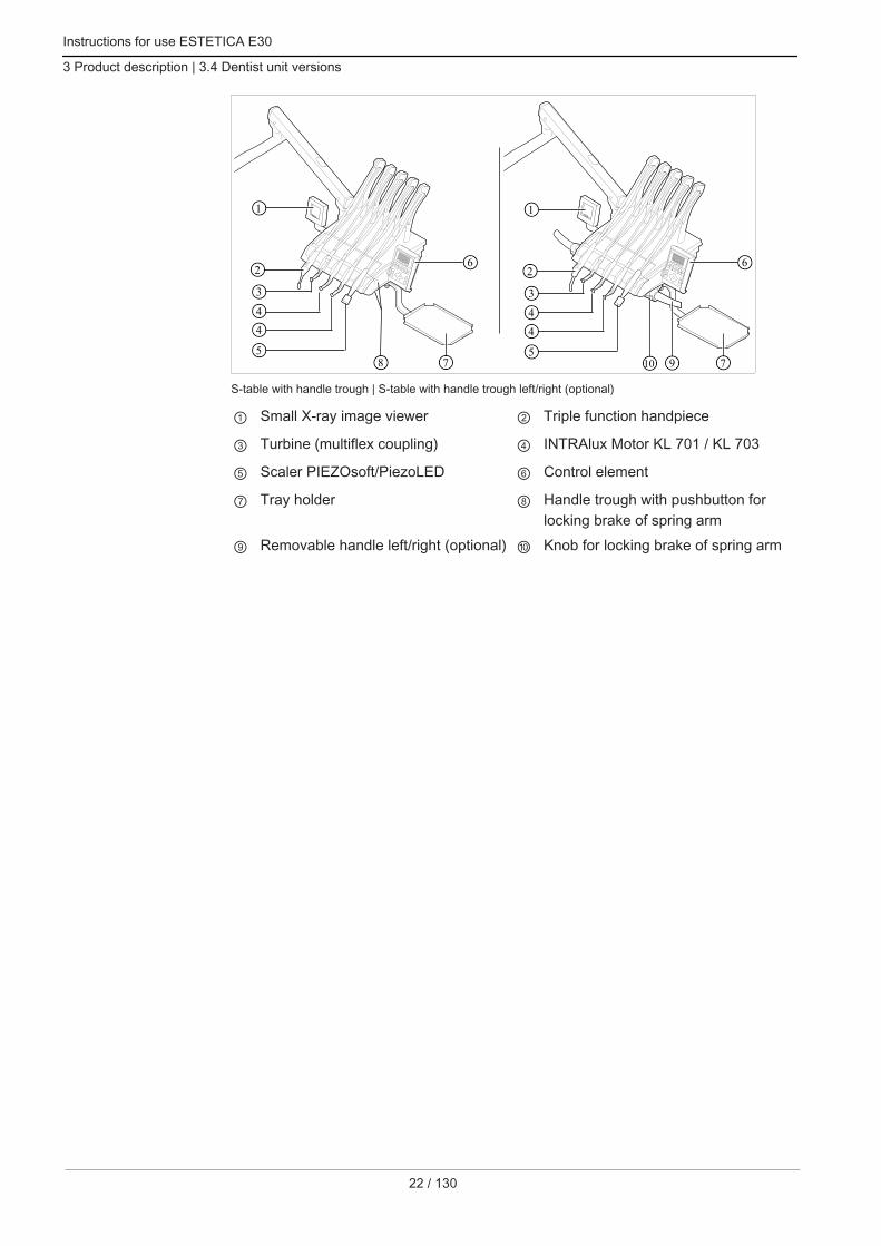
S-table with handle trough | S-table with handle trough left/right (optional)
① Small X-ray image viewer ② Triple function handpiece
③ Turbine (multiflex coupling) ④ INTRAlux Motor KL 701 / KL 703
⑤ Scaler PIEZOsoft/PiezoLED ⑥ Control element
⑦ Tray holder ⑧ Handle trough with pushbutton forlocking brake of spring arm
⑨ Removable handle left/right (optional) ⑩ Knob for locking brake of spring arm

Instructions for use ESTETICA E30
3 Product description | 3.5 Assistant unit
3.5 Assistant unit
① Triple function handpiece ② High volume aspirator
③ Control element ④ Saliva ejector
⑤ KaVo Poly One / Satelec Mini LED ⑥ Tray holder for assistant
23 / 130

Instructions for use ESTETICA E30
3 Product description | 3.6 Triple-function handpieces
24 / 130
3.6 Triple-function handpieces
32
1
4
Triple function handpiece One
① Cannula ② Water button (green ring)
③ Air button (blue ring) ④ Handpiece and hose
Triple-function handpiece
① Air button (A) ② Cannula
③ Gripping sleeve ④ Water button (W)
⑤ Ring blue

Instructions for use ESTETICA E30
3 Product description | 3.7 Controls
3.7 Controls
3.7.1 Dentist's unit TM table
FEA B C D
A Group of keys for the dental chair B Group of keys for illumination
C Group of keys for the handpieces D Group of keys for the menu
E Group of keys for hygiene F Group of keys for the timer
3.7.2 Dentist's unit S table
A
B C
D
F
E
A Group of keys for the menu B Group of keys for illumination
C Group of keys for hygiene D Group of keys for the handpieces
E Group of keys for the timer F Group of keys for the dental chair
25 / 130

Instructions for use ESTETICA E30
3 Product description | 3.7 Controls
26 / 130
3.7.3 Assistant unit
A Group of keys for hygiene B Group of keys for illumination
C Group of keys for the timer D Group of keys for the dental chair
3.7.4 Groups of keys
Group of keys for the dental chair
The keys of the assistant unit each have two functions and show two symbols.
Assistant unit key Dentist unit key Labelling"Chair up" key
"AP 0" key(automatic position 0)
"Chair down" key
"SP" key(rinsing position)
"LP" key(last position)
"AP" key(activate automatic posi‐tion)"Backrest down" key
"AP 1" key(automatic position 1)

Instructions for use ESTETICA E30
3 Product description | 3.7 Controls
Assistant unit key Dentist unit key Labelling"Backrest up" key
"AP 2" key(automatic position 2)
"Collapsed position" key
Group of keys for illumination/handpieces
Key Name Control elementKey"Operating light"
Dentist element and assis‐tant element
"Operating light dimming"key
Dentist element
Key"X-ray viewer"
Dentist element
"Direction of motor rotation"button
Dentist element
"Preselected spray" button Dentist element
"Cold light" button Dentist element
Group of keys for hygiene
Key Name Control element"Tumbler filler" key Dentist element and
assistant element
"Bowl rinsing" key Dentist element andassistant element
"Bell" key Dentist element
"Intensive disinfection" key Assistant element (unas‐signed key)
"HYDROclean" key Assistant element (unas‐signed key)
27 / 130
Instructions for use ESTETICA E30
3 Product description | 3.7 Controls
28 / 130
Group of keys for the menu
Group of keys for the menu
① Menu function selection keys ② Display
Group of keys for the timer
Key Name Control element"Remote Control" key unassigned key
"Additional motor drives"key
Dentist element
"Timer 1" key Dentist element andassistant element
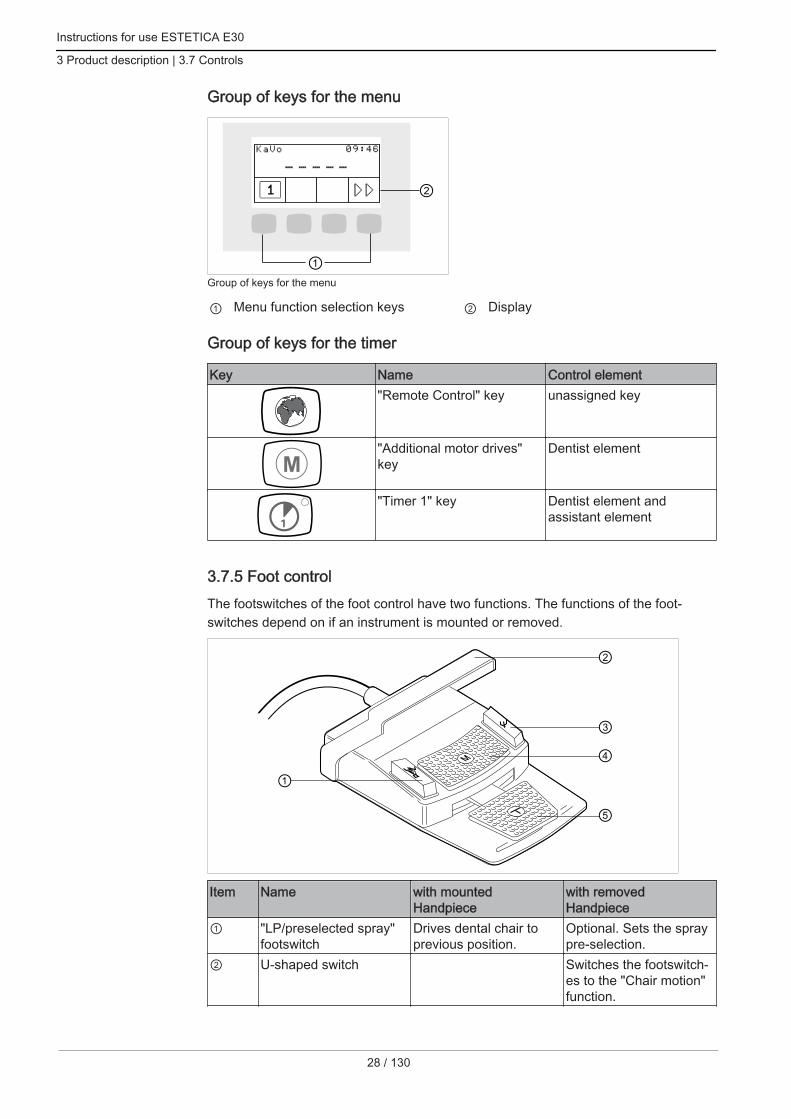
3.7.5 Foot controlThe footswitches of the foot control have two functions. The functions of the foot‐switches depend on if an instrument is mounted or removed.
Item Name with mountedHandpiece
with removedHandpiece
① "LP/preselected spray"footswitch
Drives dental chair toprevious position.
Optional. Sets the spraypre-selection.
② U-shaped switch Switches the footswitch‐es to the "Chair motion"function.

Instructions for use ESTETICA E30
3 Product description | 3.8 Rating plate and serial number plates
Item Name with mountedHandpiece
with removedHandpiece
③ "SP/blown air" footswitch Drives dental chair torinsing position.
Optional. Sets the presetblown air (Chipblower) atthe handpiece (does notapply to PiezoLED).
④ "Chair position/directionof motor rotation" 4-wayswitch
Changes the position ofthe dental chair.
Selects the direction ofmotor rotation (for KL701 / KL 703 motor).
⑤ "Preselection of level/handpieces" foot-pedal
Preselection of level Starts the handpiecesand controls the speed/intensity of thehandpieces.
3.8 Rating plate and serial number plates
ESTETICA E30 and chair nameplate
2
1
Site for affixing the rating plate and serial number plate
① Serial number plate of the chair ② Rating plate
SN Serial number
29 / 130

Instructions for use ESTETICA E30
3 Product description | 3.8 Rating plate and serial number plates
30 / 130
Read and take note of the content of accompanying documents
Type B applied part
Type BF applied part
2 min
18 min
ED 10%
Operating mode:Operating time of the patient chair: 2 minutesPause time of the patient chair: 18 minutes(The permissible operating times correspond to common dental procedure.)
Fuse ratings:100/110/115/120/127/220/230/240 V AC = T6.3 A 250 V
For disposal information, see also: Purpose - Intended use
CE mark according to Medical Devices Directive EC 93/42
VDE mark
DVGW ID(Deutscher Verein des Gas- und Wasserfaches e.V.)(Equipment-dependent DVGW mark with certification number)
See also:2 Technical Data
Serial number plate and dentist element ID
Rating plate dentist element (e.g. table T) / marking of the application parts of Type BF
Site of attachment of rating plate and type BF applied parts ID on dentist element

Instructions for use ESTETICA E30
3 Product description | 3.8 Rating plate and serial number plates
Type Device typeSN Year of manufacture - serial numberREF Material number
31 / 130
Instructions for use ESTETICA E30
3 Product description | 3.8 Rating plate and serial number plates
32 / 130
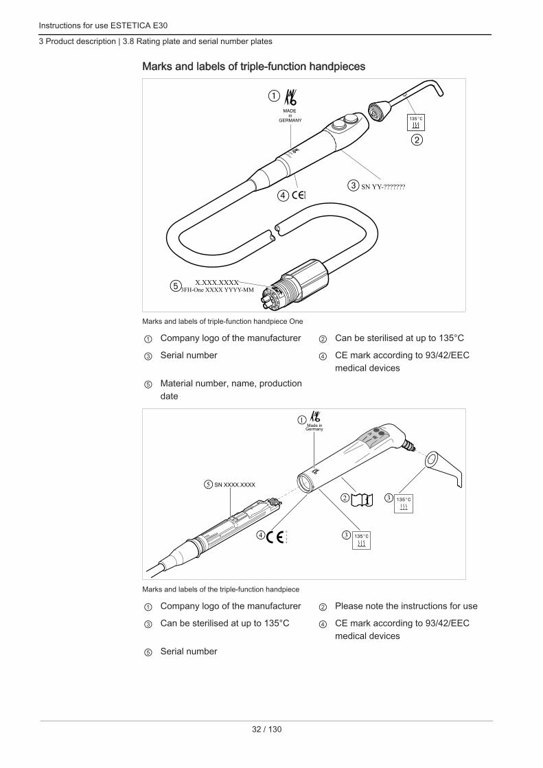
Marks and labels of triple-function handpieces
3FH-One XXXX YYYY-MM
SN YY-???????
X.XXX.XXXX
Marks and labels of triple-function handpiece One
① Company logo of the manufacturer ② Can be sterilised at up to 135°C
③ Serial number ④ CE mark according to 93/42/EECmedical devices
⑤ Material number, name, productiondate
32
1
4
5
3
Marks and labels of the triple-function handpiece
① Company logo of the manufacturer ② Please note the instructions for use
③ Can be sterilised at up to 135°C ④ CE mark according to 93/42/EECmedical devices
⑤ Serial number
Instructions for use ESTETICA E30
3 Product description | 3.8 Rating plate and serial number plates
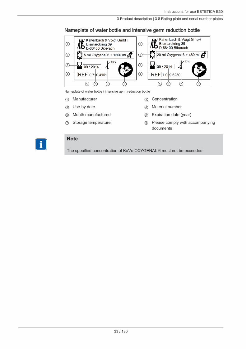
Nameplate of water bottle and intensive germ reduction bottle
3
2
1
4
75 6 8
3
2
1
4
75 6 8
Nameplate of water bottle / intensive germ reduction bottle
① Manufacturer ② Concentration
③ Use-by date ④ Material number
⑤ Month manufactured ⑥ Expiration date (year)
⑦ Storage temperature ⑧ Please comply with accompanyingdocuments
Note The specified concentration of KaVo OXYGENAL 6 must not be exceeded.
33 / 130

Instructions for use ESTETICA E30
3 Product description | 3.9 Technical data
34 / 130
3.9 Technical data
Drilling template and setup plan
Layout plan (Mat. no. 1.009.2781)
Electrical system
Electrical lead 3 x 1.5 mm2 (customer-provided fuse pro‐tection 10 A) 3 x 2.5 mm2
(customer-provided fuse protection 16 A)
Free end above the floor 1 000 mm
Input voltages 100/110/115/120/127/220/230/240 V AC
Frequency 50/60 Hz
Factory-set mains input voltage See nameplate
Power consumption 100 to 900 VA
Customer-provided fuse protection Auto-mat C16 or screw-plug fuse 10 A
Protective conductor above floor See DIN VDE 0100-710, 1000 mm
Heat emission 360 to 3240 kJ/h
Heat emission Ø 900 kJ/h
Degree of soiling 2
Installation category II
Mark of approval CE / DVGW / VDE
Foot control IPX1 (moisture protection)
Triple-function handpiece OneFlush the water and air passages for 20 to 30 seconds before working at the begin‐ning of the day.
Water pressure 1.5 ± 0.3 bar; flow pressure; probe tip(1.009.6634)
Water flow 90 ± 15 ml/min
Air pressure 1.5 ± 0.2 bar; flow pressure; probe tip(1.009.6634)
Air flow 15 ± 3 Nl/min
Triple function handpieceFlush the water and air passages for 20 to 30 seconds before working at the begin‐ning of the day.

Instructions for use ESTETICA E30
3 Product description | 3.9 Technical data
Water pressure 1.5 ± 0.3 bar; Flow pressure; 4 x manom‐eter
Max. static pressure water 2.5 ± 0.3 bar
Water flow 80 ± 10 ml/min
Air pressure 3.3 ± 0.1 bar; Flow pressure; 4 x manom‐eter
Max. dynamic pressure air 4 + 0.5 bar
Air flow 14 ± 2 Nl/min
Water supply
CAUTIONThe ESTETICA E30 treatment centre, as delivered, is not equipped with an amalgamseparator.Contamination of wastewater. Disposing wastewater, it is imperative to comply with the national regulations, in
particular with regard to amalgam loads.
NoteKaVo recommends to connect an external amalgam separator to the ESTETICAE30 treatment centre in compliance with the specifications of the manufacturer ofthe device.
NoteIf the water is very hard (above 12 °dH), a water softening device must be fitted inthe ion-exchange process.Insufficient water hardness (below 8.4 °dH) can promote the formation of algae.
NoteThe "water inlet block" assembly kit does not include a separation between thetreatment water and water supplied by the local water supply. The operator mustobserve and adhere to relevant national directives concerning the prevention ofbackflow. If these rules are not adhered to, the manufacturer can assume no liabilityfor the quality of the treatment water and the microbial re-contamination of the pub‐lic drinking water network.
WARNINGDanger of infection if the national guidelines are not observed.Contamination of the treatment water or the drinking water network. Observe and adhere to the national guidelines concerning the quality of water for
human consumption (potable water) – if available. Observe and adhere to the national guidelines concerning the prevent of reflux
(flow of water from the treatment unit to the public water network) – if relevant.
35 / 130

Instructions for use ESTETICA E30
3 Product description | 3.9 Technical data
36 / 130
WARNINGRisk of infection if the "Water inlet block" is used without additional safeguards.Contamination of the treatment water and/or drinking water supply with germs. Regarding the use of the "Water inlet block" assembly kit, please note that no dis‐
infection facility is installed in the unit, and take appropriate safeguards. If the Water bottle assembly kit is used with the enclosed dosing attachment (Mat.
no. 10020287), add the proper amount of KaVo OXYGENAL 6 (Mat. no.04893451) with each filling. For the correct amount, please refer to the instruc‐tions of the dosing attachment for water disinfection.
Water germ reduction is integrated in combination with the water bottle with manualOxygenal 6 dosing through the dosing attachment and the intensive germ reductionbottle.According to DIN EN 1717, each unit that is not listed by DVGW must be providedwith an upstream type AA, AB or AD safety device. (The DVGW water bottle kit is cer‐tified; see the following list.)When establishing a water connection, prevent brackish water pools with standing wa‐ter (also in the house plumbing).For further information, please refer to www.dvgw.de
Free drainage according to DIN EN 1717 -DVGW certified
Water bottle DVGW, reg. no.:AS-0630BT0111
Water quality Tap water
Water hardness 1.5 to 2.14 mmol/l ≙ 8.4 to 12 °dH
pH 7.2 to 7.8
Customer water filtering 80 µm
Water connection Shut-off valve with brass cone compres‐sion screw connection 3/8" to Ø 10 mmprovided
Above-floor water connection min. 50 mm, max. 105 mm with valveopened
Water inlet pressure 2.0 to 6.0 bar
Water inlet pressure 4 l/min
Diameter of the drain connection 40 mm
Above-floor drain connection 20 mm
Outflow quantity max. 4 l/min
Slope of water drain pipe downstream from device: at least 10 mmper metre
Air supply
WARNINGNon-adherence to national guidelines regarding the quality of the dental air.Infection hazard. Observe and adhere to the national guidelines regarding the quality of the dental
air - if any. Blow through the air line prior to commissioning.

Instructions for use ESTETICA E30
3 Product description | 3.9 Technical data
Air inlet pressure 5.5 to 7 bar
Air consumption of standard device max. 60 Nl/min.
Air consumption with 1 Venturi suction unit max. 105 Nl/min.
Air consumption with 2 Venturi suctionunits
max. 150 Nl/min.
Customer air filtration 50 µm
Air connection Shut-off valve with brass cone compres‐sion screw connection 3/8" to Ø 10 mmprovided
Air connection above floor level min. 50 mm, max. 105 mm with valveopened
SuctionSuction air quantity at spray mist cannula Suction vacuum at device intake
with wet suctionminimal V~250 Nl/min > 70 mbarrecommended V~300 Nl/min > 90 mbarSuction vacuum static max. < 180 mbar
NoteIf the negative static pressure is > 180 mbar, the unit must be equipped with thenegative pressure regulating valve assembly kit.
Diameter of the suction connection 40 mm
Above-floor suction connection 20 mmThe values apply to the KaVo measuring set (Mat. no. 0.411.8500).
Operating environment
WARNINGInappropriate operating conditions.Impairment of the electrical safety of the device. It is essential to comply with the operating conditions specified in the "Technical
Specifications" chapter and not to exceed those conditions.
Floor quality The quality of the flooring must meet theload bearing ability for buildingsDIN 1055 page 3 and have a pressure re‐sistance in accordance with DIN 18560 T1.
Ambient temperature +10 to +40 oC
Relative humidity 30 to 75%
Air pressure 700 hPa to 1,060 hPa
Max. elevation for operation up to 3000 m
37 / 130

Instructions for use ESTETICA E30
3 Product description | 3.9 Technical data
38 / 130
Maximum loads
Max. patient weight load 180 kg
Tray holder of the dentist element - loada‐ble up to
2 kg
Assistant unit tray holder - loadable up to 1 kg
Dentist element - loadable up to 2 kg
Transportation and storage conditions
Ambient temperature -20 to +55oC
Relative humidity 5% to 95% non-condensing
Air pressure 700 to 1,060 hPa
Weight
Treatment unit with Standard patient chair 279 kg gross, 224 kg netFor more information about the packages, please refer to Assembly Instructions

Instructions for use ESTETICA E30
4 Operation | 4.1 Switching the device on and off
4 Operation
4.1 Switching the device on and off
NoteAlways switch the machine off before leaving the office.
Switch on the device using the main switch.ð The display of the dentist unit ① shows the preselected basic menu.ð The green LED "Device turned on" lights up on the assistant unit ②.
1
2
4.2 Converting from right handed to left handed
CAUTIONCollision and damage to the unit. Ensure sufficient space for swinging. Turn off the device before conversion.
39 / 130

Instructions for use ESTETICA E30
4 Operation | 4.2 Converting from right handed to left handed
40 / 130
CAUTIONLet the instrument hose hang on the patient chair or another object. When swinging the dentist's unit and the articulation, make sure that the instru‐
ment hoses do not get caught.
① Right handed model ② Left handed model
Remove the seat.
Instructions for use ESTETICA E30
4 Operation | 4.2 Converting from right handed to left handed
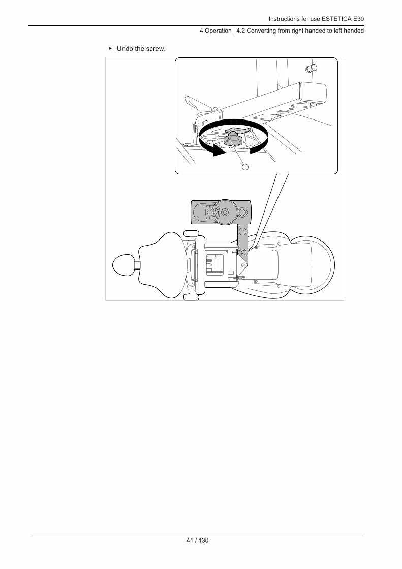
Undo the screw.
41 / 130

Instructions for use ESTETICA E30
4 Operation | 4.2 Converting from right handed to left handed
42 / 130
Swivel the dentist and assistant element to the other chair side and re-tighten thescrew.

Instructions for use ESTETICA E30
4 Operation | 4.3 Adjusting the dental chair
Undo the locking and swivel the patient unit by 180° until the locking snaps-inagain. patient element
Fasten the seat again proceeding in reverse order.
4.3 Adjusting the dental chair
4.3.1 Adjusting the armrest (optional)To make it easier for the patient to sit in the chair, the armrest can be swung up.
43 / 130

Instructions for use ESTETICA E30
4 Operation | 4.3 Adjusting the dental chair
44 / 130
CAUTIONThe patient's hands are in a bad position when the chair is risingDanger of crushing fingers between the backrest and armrest. Make sure that the patient is sitting in the right position (especially children).
4.3.2 Adjust head rest
Setting locking dial of 2-joint headrest
CAUTIONAdjusting the headrest.Injury of neck muscles. Make sure that the patient is aware of the headrest setting. Patients need to raise their head slightly during adjustment.

Instructions for use ESTETICA E30
4 Operation | 4.3 Adjusting the dental chair
Push in or pull out the headrest depending on the patient's size.
To swing the headrest, turn the locking dial to the left, move the headrest into po‐sition, and turn the dial to the right to lock it.
To remove the headrest cushion, remove the screw ②, pull the cushion ① upslightly, and remove it to the front.
4.3.3 Positioning the dental chair manually
CAUTIONDanger of injury from overload or dynamic load.The patient chair might collapse. Do not subject the patient chair to a load exceeding its limit (180 kg). Do not subject the patient chair to dynamic loads.
CAUTIONMotorised movement of the chairThe patient or treatment personnel can be clamped or crushed. Monitor the patient and treatment personnel when changing the patient's position.
45 / 130

Instructions for use ESTETICA E30
4 Operation | 4.3 Adjusting the dental chair
46 / 130
Positioning the chair and backrest manually using the dentist orassistant unit
Use the following buttons to adjust the chair height and position of the backrest:
Key FunctionThe chair moves up.
The chair moves down.
The backrest moves upward.
The backrest moves downward.
Press the related key.ð The chair or backrest moves in the desired direction.
Positioning the chair and backrest manually using the foot control
The 4-way switch of the foot control assumes the function of the button wheel on thedentist unit when manually positioning the dental chair.
See also:2 Positioning the dental chair manually
RequirementAll instruments are in their holder. Chair up: Move the cross switch on the foot control in direction ①.
Chair down : Move the cross switch on the foot control in direction ③.
Backrest up: Move the cross switch on the foot control in direction ②.
Backrest down: Move the cross switch on the foot control in direction ④.

Instructions for use ESTETICA E30
4 Operation | 4.3 Adjusting the dental chair
4.3.4 Automatic positioning of dental chair
CAUTIONDanger of injury from overload or dynamic load.The patient chair might collapse. Do not subject the patient chair to a load exceeding its limit (180 kg). Do not subject the patient chair to dynamic loads.
CAUTIONDanger of crushing during automatic chair movement.The patient or treatment personnel can be clamped. Monitor the patient and treatment personnel when changing the chair position.
The chair position can be adjusted continuously.Automatic positions can be saved, and the saved positions can be recalled by thepush of a button.
Recalling automatic positions with the dentist unit
The following keys can be used to recall saved chair positions.
Key OperationMove to the rinsing position.
The last position before actuating the SP is assumed.
Move to automatic position 0.
Move to automatic position 1.
Move to automatic position 2.
Move to the collapsed position.
Briefly press the desired button.ð Chair automatically moves to the stored position.ð Upon arrival at the stored position, the display diode on the button is turned on.
Saving automatic positions with the dentist unit
Recommended assignment of buttons:"SP" button: rinsing position"AP 0" button: entry and exit position"AP 1" button: treatment position, e.g. for lower jaw treatment"AP 2" button: treatment position, e.g. for upper jaw treatment"Collape position" button: collapse position Move the chair to the desired position.
47 / 130

Instructions for use ESTETICA E30
4 Operation | 4.3 Adjusting the dental chair
48 / 130
To save the chair position, press "AP 0", "AP 1", "AP 2", "SP" or "Collapsed posi‐tion" button until you hear a signal.
ð The display diode of the pressed button is turned on. The chair position is saved.
See also:2 Manual positioning of the patient chair using the MEMOdent control element
Last position
After the "LP" button is pressed, the chair moves into its position before the "SP" but‐ton was pressed.
NoteThe memory is erased when you turn off the device. After turning on the deviceagain (for example in the morning or after lunch), the chair does not execute a spe‐cific movement when you press the "LP" button.
Recalling automatic positions with the assistant unit
Briefly press the "AP" key.
ð The LEDs of the "AP 0", " AP 1", " AP 2", "SP", and "LP" keys flash for approxi‐mately four seconds.
During these four seconds, briefly press the "AP 0", " AP 1", " AP 2", "SP" or "LP"key.
ð The chair moves into the selected automatic position.
Saving automatic positions with the assistant unit
NoteThe automatic position "Last position" is saved on the "LP" button. Press the "LP"button for the chair to automatically move to the last position before the rinsing posi‐tion. The "LP" button cannot be assigned to another automatic position.
Move the chair to the desired position.
Briefly press the "AP" key.
ð The LEDs of the "AP 0", " AP 1", " AP 2", "SP", and "LP" keys flash for approxi‐mately four seconds.
During these four seconds, press the "AP 0", "AP 1", "AP 2", "SP" or "LP" button,until a signal sound is transmitted.
ð LED of the pressed button lights up. The chair position is saved.

Instructions for use ESTETICA E30
4 Operation | 4.3 Adjusting the dental chair
Recalling automatic positions with the foot control
NoteIf an instrument is removed, the chair functions of the foot control are blocked. Theblocking can be removed by briefly pressing the stirrup switch. The functions arethen available.
① Spray preselection/AP footswitch ② Footswitch blowing air/AP (optional)
③ Foot pedal
The chair positions can be recalled with two foot switches; the standard setting is asfollows: "Spray selection" foot switch: automatic position "LP" (last position)
"Blown air" foot switch: automatic position "SP" (rinsing position)
Move the chair when the instrument is mounted
Press the "SP" foot-operated button.
or
Press the "LP" foot-operated button.
ð The chair moves into the selected automatic position.
Move the chair when the instrument is removed
NoteIf an instrument is removed, the chair functions of the foot control are blocked. Theblocking can be removed by briefly pressing the stirrup switch. The functions arethen available.
49 / 130

Instructions for use ESTETICA E30
4 Operation | 4.3 Adjusting the dental chair
50 / 130
Press the stirrup switch and then the "Preselected spray" or "Blown air" footswitch.
ð The chair moves into the selected automatic position.
Saving an automatic position with the foot control
① Spray preselection/AP footswitch ② Footswitch blowing air/AP (optional)
③ Foot pedal
The chair positions can be saved on two footswitches; the standard setting is as fol‐lows: "Spray default" footswitch: "LP" automatic position (last position)
"Blown air" footswitch: "SP" automatic position (rinsing position)
Hold down the foot pedal and foot-operated button "SP", and simultaneouslypress any button for an automatic position ("AP 0", "AP 1", "AP 2" or "SP") on thedentist or assistant unit until you hear a beep.
ð The automatic position is saved to the foot-operated button.or
Hold down the foot pedal and foot-operated button "LP", and simultaneously pressany button for an automatic position ("AP 0", "AP 1", "AP 2" or "SP") on the dentistor assistant unit until you hear a beep.
ð The automatic position is saved to the foot-operated button.
4.3.5 Safety shut-offTo prevent collisions arising from the movement of the patient chair, safety shutoffswitches are installed to protect the patient and practice personnel from injury and thetreatment unit from damage.

Instructions for use ESTETICA E30
4 Operation | 4.3 Adjusting the dental chair
CAUTIONDamage to the assistant element and dental chair.Despite some safety shut-downs being present, certain positions of the assistant unitmay collide with the dental chair. Keep the assistant unit out of the range of motion of the patient chair. Always monitor the chair movement.
CAUTIONPinching from the treatment chair.The safety shutoff of the treatment chair is activated by lifting the respective compo‐nent. Depending on the patient's body weight and the leverage, more force can beexerted on the object to be triggered than is necessary to trigger the switching func‐tion. The treatment personnel must move outside of the chair's swinging range when‐
ever the chair moves.
CAUTIONRisk of injury when moving the patient or patient chair.The patient or treatment personnel can be pinched or crushed. Position all moving parts, such as dentist element, assistant element, operating
light, screens, etc., outside the collision range when you move the patient or pa‐tient chair.
The safety cut-offs can be found at the following places on the treatment unit.
5
Pos.no.
Safety switch-off actu‐ated
LED on assistant ele‐ment
LED on dentist element
① Bracket on the foot con‐trol
② Assistant element
51 / 130

Instructions for use ESTETICA E30
4 Operation | 4.3 Adjusting the dental chair
52 / 130
Pos.no.
Safety switch-off actu‐ated
LED on assistant ele‐ment
LED on dentist element
③ Backrest
④ Kickplate
⑤ SeatFor right/left conversionwith bench removed
The safety shutoff occurs went a movement angle has been exceeded, or part of thetreatment unit collides with an object.If a person or object actuates a safety shutoff, the chair immediately stops moving.The fact that the safety shutoff has been activated is displayed by the correspondingdisplay flashing on the dentist or assistant unit.
NoteThe chair's position cannot be changed with the key wheels when a safety shutoff isactivated.
To deactivate an activated safety shutoff, remove the triggers from the to therange of movement of the stool.
CAUTIONChanging the chair's position when the safety circuit is on.Personal injury.Damage to the device. When changing position, do not move the chair against the active safety circuit
when actively shutting off the safety circuit.
CAUTIONPinching from the treatment chair.The safety shutoff of the treatment chair is activated by lifting the respective compo‐nent. Depending on the patient's body weight and the leverage, more force can beexerted on the object to be triggered than is necessary to trigger the switching func‐tion. The treatment personnel must move outside of the chair's swinging range when‐
ever the chair moves.
To allow the chair to move freely, it can also be moved when the safety circuit is on.Use this function for repair purposes only.
Press and hold down both the "SP" and "LP" keys on the dentist element.
or
Press and hold down the "LP/AP" key on the assistant element.
Move the chair using the button wheel buttons of the chair.
Instructions for use ESTETICA E30
4 Operation | 4.4 Moving the patient chair
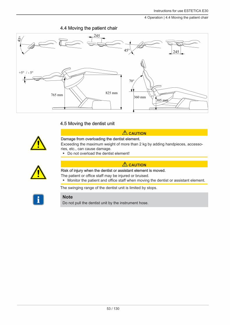
4.4 Moving the patient chair
45° 245
45° 245
360 mm
70°
825 mm
+5° / - 5°
305 mm765 mm
4.5 Moving the dentist unit
CAUTIONDamage from overloading the dentist element.Exceeding the maximum weight of more than 2 kg by adding handpieces, accesso‐ries, etc., can cause damage. Do not overload the dentist element!
CAUTIONRisk of injury when the dentist or assistant element is moved.The patient or office staff may be injured or bruised. Monitor the patient and office staff when moving the dentist or assistant element.
The swinging range of the dentist unit is limited by stops.
NoteDo not pull the dentist unit by the instrument hose.
53 / 130

Instructions for use ESTETICA E30
4 Operation | 4.5 Moving the dentist unit
54 / 130
① Knob for locking brake of spring arm
To adjust the height of the dentist unit, release the brake ① adjust the height, andlock the brake again.
4.5.1 Moving the dentist unit TM
CAUTIONExcessive load on the support systemThe patient or treatment personnel may be injured.The support system may be damaged. Do not exceed the permissible maximum weight (generated e.g. by instruments
and accessories). Do not use the swinging arm for a support!
25°
25°
80°
80°
160°
160°
120° 120°

Instructions for use ESTETICA E30
4 Operation | 4.6 Moving the patient unit
4.5.2 Moving the dentist unit S
CAUTIONRisk of injury by suspended instruments (S table).Patients may get injured by sharp instrument tips. When you move the dentist's unit, make sure that nobody is injured. Alert patients and care providers to the risk of injury.
25°
25°
80°
80°
160°
160°
120° 120°
4.6 Moving the patient unitThe device body can be swivelled away from the patient chair by 60o.
The spittoon bowl can be removed.
55 / 130

Instructions for use ESTETICA E30
4 Operation | 4.6 Moving the patient unit
56 / 130
4.6.1 Moving the patient element (optional)
CAUTIONThe left armrest can collide with the manually adjusted patient's unit when the chairmoves.Injury hazard. Each time before the chair is adjusted (automatic and manual), swing the manual‐
ly adjusted patient's unit into resting position.
NoteNo liquids may be emptied into the mouth rising basin when the devices is turnedoff. Mechanical and electronic damage could occur as a result of overflowing liquid.
The spittoon bowl of the swivelling patient element (optional) can be swivelled by ap‐prox. 180o: 90o each to the left and right.
Instructions for use ESTETICA E30
4 Operation | 4.7 Attaching the tray holder (optional)
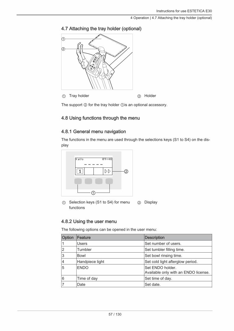
4.7 Attaching the tray holder (optional)
① Tray holder ② Holder
The support ② for the tray holder ①is an optional accessory.
4.8 Using functions through the menu
4.8.1 General menu navigationThe functions in the menu are used through the selections keys (S1 to S4) on the dis‐play
① Selection keys (S1 to S4) for menufunctions
② Display
4.8.2 Using the user menuThe following options can be opened in the user menu:
Option Feature Description1 Users Set number of users.2 Tumbler Set tumbler filling time.3 Bowl Set bowl rinsing time.4 Handpiece light Set cold light afterglow period.5 ENDO Set ENDO holder.
Available only with an ENDO license.6 Time of day Set time of day.7 Date Set date.
57 / 130

Instructions for use ESTETICA E30
4 Operation | 4.8 Using functions through the menu
58 / 130
Option Feature Description8 Time/date display mode Set display mode for time of day and
date:
Time of day only
Time of day without seconds
Time of day and date
Date only9 LCD Set contrast of LCD display.10 Language Set menu language:
Deutsch
English
Italiano
Français
Castellano13 License Display of activated licenses:
ENDO: Endo function
PLED: PiezoLED function
FCR: (foot control) control ofCONEXIO by foot control
14 Firmware Display current firmware version.
① Selection keys (S1 to S4) for menufunctions
② Display
Press the "Next" key (S4) to start-up the user menu.ð The user menu displays options and parameters that can be set and changed by
the user.
Press the "Save" (S1) key to save the selection made.

Instructions for use ESTETICA E30
4 Operation | 4.8 Using functions through the menu
Option 1: Set number of users
S1 S2 S3 S4
S1 S2 S3 S4
Press the "S1", "S2", "S3" key to select user 1, 2, and 3, respectively.
Press the "S4" button to call up the second level.
Press the "S1", "S2", "S3" key to select user 4, 5, and 6, respectively.
Option 2: Set tumbler filling time
S1 S2 S3 S4
2. BecherfüllzeitEinstellung: 7.0s
Press the "reduce value" or "increase value" key to select a tumbler filling timefrom 0 - 51 seconds.
Option 3: Set bowl rinsing time
S1 S2 S3 S4
Press the "reduce value" or "increase value" key to select a bowl rinsing time from1.0 - 50.0 seconds. Interval: 0.2 seconds.
59 / 130

Instructions for use ESTETICA E30
4 Operation | 4.8 Using functions through the menu
60 / 130
Option 4: Set LUX afterglow period
S1 S2 S3 S4
Press the "reduce value" or "increase value" key to set the afterglow period be‐tween 0 to 10 seconds. The default value is 3 seconds.
Option 5: Set ENDO holder
S1 S2 S3 S4
Press the "increase value" or "reduce value" keys to set the selected holder.
Option 6: Set the time of day
S1 S2 S3 S4
6
Press the "SET" (S2) key to change the values of minutes and hours.ð The value to be changed flashes.
Press the "Save" (S1) key to save the selection made.
S1 S2 S3 S4
6

Instructions for use ESTETICA E30
4 Operation | 4.8 Using functions through the menu
Press the "reduce value" or "increase value" key to set the marked time of day.
Press the "SS:MM" (S1) key to switch between hours and minutes.
Press the "Save" (S4) key to save the values and switch to the SET display.
Option 7: Set the date
S1 S2 S3 S4
7
Press the "SET" (S2) key to change the values of day, month, and year.ð The value to be changed flashes.
Press the "Save" (S1) key to save the selection made.
S1 S2 S3 S4
7
Press the "reduce value" or "increase value" key to set the marked value.
Press the "SS:MM" (S1) key to switch between day, month, and year.
Press the "Save" (S4) key to save the values and switch to the SET display.
Option 8: Set display mode for time of day and date
S1 S2 S3 S4
8
61 / 130

Instructions for use ESTETICA E30
4 Operation | 4.8 Using functions through the menu
62 / 130
Press the "reduce value" or "increase value" key to set the display mode of date/time.
The following displays can be selected: time of day only, time of day<no seconds>only, time of day and date, date only, day of the week, no display
Option 9: Setting the display contrast
S1 S2 S3 S4
9
Press the "reduce value" or "increase value" key to set the contrast of the LCDdisplay.
Option 10: Setting the menu language
S1 S2 S3 S4
0
Press the "reduce value" or "increase value" key to select the menu language.
The following languages can be selected: Deutsch, English, Italiano, Francais,Castellano.
Option 13: Displaying the activated licenses
S1 S2 S3 S4
13 LizenzENDO PLED FCR
Displays the activated licenses: ENDO: Endo function
PLED: PiezoLED function
FCR: (foot control) control of CONEXIO by foot control

Instructions for use ESTETICA E30
4 Operation | 4.8 Using functions through the menu
Option 14: Displaying the firmware version
S1 S2 S3 S4
14
The firmware version is displayed
4.8.3 Standby menuThe stand-by menu is used to start the device.The device switches to the stand-by menu upon closing of the handpiece and endomenus.
S1 S2 S3 S4
Press the "Next" key (S4) to start-up the user menu.
Service and error messages in the stand-by menuService and error messages are displayed in the stand-by menu through the "!" sym‐bol.
S1 S2 S3 S4
Press the "S2" button to display messages.
S1 S2 S3 S4
Press the function keys to navigate between the messages.
63 / 130

Instructions for use ESTETICA E30
4 Operation | 4.8 Using functions through the menu
64 / 130
Key SettingsS2 Previous messageS3 Next messageS4 Switch to stand-by menu
Error messages in the status display
See also:2 Troubleshooting
4.8.4 Selecting the dentistThe first symbol in the stand-by menu displays the current user.
S1 S2 S3 S4
Press the "S1" key to start the user selection menu.
User selection (max. 6 users)The user selection menu displays the available users.
S1 S2 S3 S4
S1 S2 S3 S4
Press the "S1", "S2", "S3" key to select user 1, 2, and 3, respectively.
Press the "S4" button to call up the second level.
Press the "S1", "S2", "S3" key to select user 4, 5, and 6, respectively.
4.8.5 Instruments menuhandpiece-specific values are displayed and adjusted in the menu.The display depends on which instrument was withdrawn.

Instructions for use ESTETICA E30
4 Operation | 4.8 Using functions through the menu
Changing motor settings in the menu
NoteFollowing instructions for use, service instructions and installation instructions in theinstrument packaging.
Motor statusThe status of a handpiece is displayed on the display or control keys once a hand‐piece is taken out.
S1 S2 S3 S4
Setting Actuation PaneMotor speed Foot control DisplayLight intensity Foot control, control keys DisplayDirection of motor rotation Foot control, control keys LED control keysSpray status Foot control, control keys LED control keys
Adjusting the motor Settings can be changed using the corresponding keys on the control panel or on
the foot control. Motor speed is set with the foot control only. The direction of motor rotation, cooling status and light intensity are set with the
foot control or the control keys.ð The current settings are saved and activated the next time the handpiece is taken
out.
PIEZOsoft/PiezoLED
Note The setting of the mode is only available in combination with a PiezoLED UltrasonicScaler. The PiezoLED menu and all PiezoLED functions are only available if a Pie‐zoLED license is existent.
Setting the PIEZOsoft
The status of the handpiece is shown on the display when the PIEZOsoft is being tak‐en out: Intensity Settings can be changed using the corresponding keys on the control panel or on
the foot control. The light intensity is set with the foot control only. Modus, spray, is set with the foot control or the control keys.
65 / 130

Instructions for use ESTETICA E30
4 Operation | 4.8 Using functions through the menu
66 / 130
ð The current settings are saved and activated the next time the handpiece is takenout.
S1 S2 S3 S4
Setting the PiezoLED
The status of the handpiece is shown on the display when the PiezoLED is being tak‐en out. Intensity
Mode
Light intensity Settings can be changed using the corresponding keys on the control panel or on
the foot control. The light intensity is set with the foot control only. Modus, spray, light on/off are set with the foot control or the control keys.ð The current settings are saved and activated the next time the handpiece is taken
out.
S1 S2 S3 S4
Power output as a function of operating mode and tip load

Instructions for use ESTETICA E30
4 Operation | 4.8 Using functions through the menu
Power output as a function of device pre-setting (foot control) and tip load (shown using modes P3 and E asexamples)
NoteIf you stay in the range of dynamic response, the treatment is ensured to be gentle.The output is adjusted according to load.
4.8.6 ENDO menu (optional)
NoteThe functions of the ENDO menu are available only if an ENDO license is existent.
Start-up ENDO menu
The ENDO menu is started-up through: taking the ENDO motor out of the dentist element (setting in user menu, option 5)
activating the (M) "Additional motor drives" key afterwards
ENDO status menu
S1 S2 S3 S4
The status of the ENDO motor is displayed in the ENDO menu:
Parameters ValuesTransmission factor 1:1, 3:1Parameter memory P1,P2,P3,P4,P5,P6Torque mode TQ-Ctrl, Autoreverse, AutoRev/Forw.Direction of motor rotation R, LSpeed 100 to 6,000 rpmTorque Transmission ratio 1:1: 0.15 to 2.50 Ncm
Transmission ratio 3:1: 0.4 to 8.0 Ncm
67 / 130

Instructions for use ESTETICA E30
4 Operation | 4.8 Using functions through the menu
68 / 130
Using the ENDO menu
Displaying parameters Press the respective keys on the display to navigate between parameters.
S1 S2 S3 S4
Key SettingsS1 (short)(Briefly) press the "SP/Blown air" foot-operatedbutton
Displays the next set of parameters1,2,3,4,5,6,1,..(ring counter)
S4 Selects the ENDO options menu
Setting the ENDO menu Press the "S1" key for an extended time to select the ENDO settings menu. The
individual parameters can be set and changed in this menu.
S1 S2 S3 S4
Key SettingsS1 Saves the parameters.
Selects the ENDO menu.S2 Changes the value.S3 Changes the value.S4 Moves the flashing cursor:
Torque mode, speed, torque, torque mode, ... (ring counter).
Set torque mode The torque mode parameter can be changed after selecting it in the settings
menu.ð The selected parameter is marked by a flashing cursor on the display.

Instructions for use ESTETICA E30
4 Operation | 4.8 Using functions through the menu
S1 S2 S3 S4
Key SettingsS1 Saves the parameters
Selects the ENDO menuS2 Changes the torque mode
Autoreverse, Torque Control only, Autorev. / Forward, Autoreverse,..(ringcounter)
S3 Changes the torque modeAutoreverse, Autorev. / Forward, Torque Control only, Autoreverse,..(ringcounter)
S4 Moves the flashing cursor
Setting the speed The speed parameter can be changed after selecting it in the settings menu.ð The selected parameter is marked by a black triangle on the display.
S1 S2 S3 S4
Key SettingsS1 Saves the parameters
Selects the ENDO menuS2 Changes the speed
Range: 100 rpm to 500 rpm: in 10 rpm incrementsRange: 500 rpm to 1,000 rpm: in 50 rpm incrementsRange: 1,000 rpm to 6,000 rpm: in 100 rpm increments
S3 Changes the speedRange: 100 rpm to 500 rpm: in 10 rpm incrementsRange: 500 rpm to 1,000 rpm: in 50 rpm incrementsRange: 1,000 rpm to 6,000 rpm: in 100 rpm increments
S4 Moves the flashing cursor
Setting the torque The torque parameter can be changed after selecting it in the settings menu.ð The selected parameter is marked by a black triangle on the display. Sets the maximum torque.ð The torque is limited to the set maximal value.ð The ENDO warning signal is issued when 90% of the pre-set maximal value are
reached.
69 / 130

Instructions for use ESTETICA E30
4 Operation | 4.8 Using functions through the menu
70 / 130
S1 S2 S3 S4
Key SettingsS1 Saves the parameters
Selects the ENDO settings menuS2 Changes the torque
1:1 transmission ratioRange: 0.15 Ncm to 2.5 Ncm: in 0.05 Ncm incrementsRange: 1% to 100%: in 2% increments3:1 transmission ratioRange: 0.4 Ncm to 8.0 Ncm: in 0.05 Ncm incrementsRange: 1% to 100%: in 1% increments
S3 Changes the torque1:1 transmission ratioRange: 0.15 Ncm to 2.5 Ncm: in 0.05 Ncm incrementsRange: 1% to 100%: in 2% increments3:1 transmission ratioRange: 0.4 Ncm to 8.0 Ncm: in 0.05 Ncm incrementsRange: 1% to 100%: in 1% increments
S4 Moves the flashing cursor
ENDO options menu Press the "S4" key to select the ENDO options menu.
S1 S2 S3 S4
Option 1: Transmission ratio Press the "S2" or "S3" key to set the transmission factor.
S1 S2 S3 S4

Instructions for use ESTETICA E30
4 Operation | 4.8 Using functions through the menu
Key SettingsS1 Saves the option
Selects the ENDO menuS2 Changes the transmission factor
1:1 or 3:1S3 Changes the transmission factor
1:1 or 3:1S4 Selects the next option
Option 2: Torque Press the "S2" or "S3" key to change the torque setting display.
S1 S2 S3 S4
Key SettingsS1 Saves the option
Selects the ENDO menuS2 Changes the torque setting display
Unit: % or NcmTransmission ratio 1:1: 100% = 2.5 NcmTransmission ratio 3:1: 100% = 8.0 Ncm
S3 Changes the torque setting displayUnit: % or NcmTransmission ratio 1:1: 100% = 2.5 NcmTransmission ratio 3:1: 100% = 8.0 Ncm
S4 Selects the next option
Option 3: AutoRev. / Fwd Press the "S2" or "S3" key to set the period of time after which the motor rotates
clockwise automatically. This dispenses with having to stop it using the foot con‐trol.
S1 S2 S3 S4
Key SettingsS1 Saves the option
Selects the ENDO menu
71 / 130
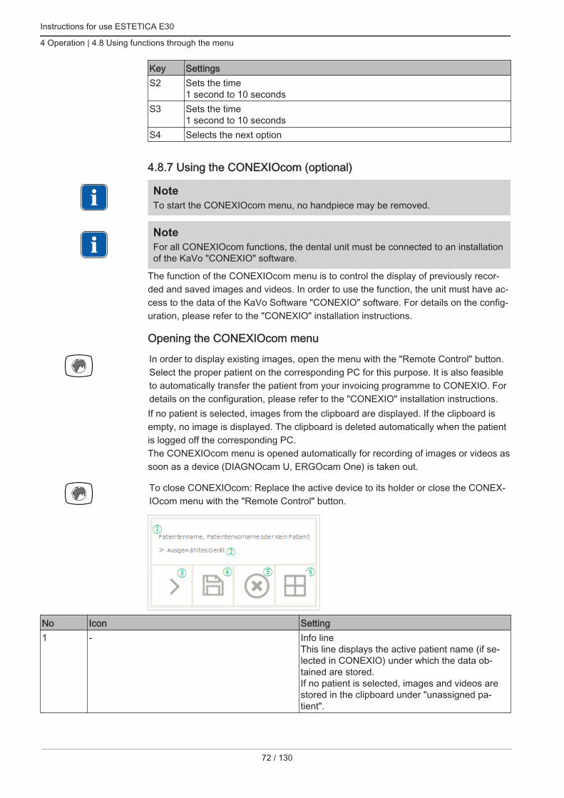
Instructions for use ESTETICA E30
4 Operation | 4.8 Using functions through the menu
72 / 130
Key SettingsS2 Sets the time
1 second to 10 secondsS3 Sets the time
1 second to 10 secondsS4 Selects the next option
4.8.7 Using the CONEXIOcom (optional)
NoteTo start the CONEXIOcom menu, no handpiece may be removed.
NoteFor all CONEXIOcom functions, the dental unit must be connected to an installationof the KaVo "CONEXIO" software.
The function of the CONEXIOcom menu is to control the display of previously recor‐ded and saved images and videos. In order to use the function, the unit must have ac‐cess to the data of the KaVo Software "CONEXIO" software. For details on the config‐uration, please refer to the "CONEXIO" installation instructions.
Opening the CONEXIOcom menu
In order to display existing images, open the menu with the "Remote Control" button.Select the proper patient on the corresponding PC for this purpose. It is also feasibleto automatically transfer the patient from your invoicing programme to CONEXIO. Fordetails on the configuration, please refer to the "CONEXIO" installation instructions.If no patient is selected, images from the clipboard are displayed. If the clipboard isempty, no image is displayed. The clipboard is deleted automatically when the patientis logged off the corresponding PC.The CONEXIOcom menu is opened automatically for recording of images or videos assoon as a device (DIAGNOcam U, ERGOcam One) is taken out.
To close CONEXIOcom: Replace the active device to its holder or close the CONEX‐IOcom menu with the "Remote Control" button.
No Icon Setting1 - Info line
This line displays the active patient name (if se‐lected in CONEXIO) under which the data ob‐tained are stored.If no patient is selected, images and videos arestored in the clipboard under "unassigned pa‐tient".

Instructions for use ESTETICA E30
4 Operation | 4.8 Using functions through the menu
No Icon Setting2 - If a device is active, the device type is shown.
The following is implemented at this time:DIAGNOcam UERGOcam One
3 Next image/videoTo be able to communicate efficiently with the pa‐tient, individual images can be selected and dis‐played directly. This uses a rolling system thatadvances from left to right and from top to bot‐tom.
4 Save image/videoPress briefly - saves the selected image/video.Press long - all images/videos are saved in theSwap Tray.If no patient is selected, the images stay in theclipboard and cannot be saved permanently. Assoon as a patient is selected, these temporarydata in the clipboard are deleted.When an active patient is logged off (or a newpatient is logged on) in CONEXIO, a query isshown asking whether the images in the shall bedeleted or saved. Data deleted at this point can‐not be restored subsequently.
5 Discard image/videoPress briefly - deletes the selected image/videoPress long - all images/videos in the clipboardare deleted
6 Screen display:This button changes the display on the monitor.The following settings can be made:1/2/4/6 – number of images displayed.The live image is always shown as the last imagein split view.
73 / 130
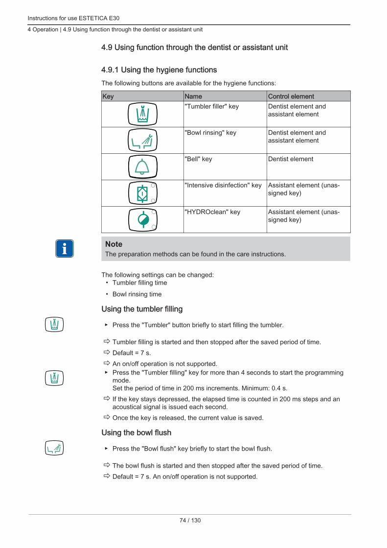
Instructions for use ESTETICA E30
4 Operation | 4.9 Using function through the dentist or assistant unit
74 / 130
4.9 Using function through the dentist or assistant unit
4.9.1 Using the hygiene functionsThe following buttons are available for the hygiene functions:
Key Name Control element"Tumbler filler" key Dentist element and
assistant element
"Bowl rinsing" key Dentist element andassistant element
"Bell" key Dentist element
"Intensive disinfection" key Assistant element (unas‐signed key)
"HYDROclean" key Assistant element (unas‐signed key)
NoteThe preparation methods can be found in the care instructions.
The following settings can be changed: Tumbler filling time
Bowl rinsing time
Using the tumbler filling
Press the "Tumbler" button briefly to start filling the tumbler.
ð Tumbler filling is started and then stopped after the saved period of time.ð Default = 7 s.ð An on/off operation is not supported. Press the "Tumbler filling" key for more than 4 seconds to start the programming
mode. Set the period of time in 200 ms increments. Minimum: 0.4 s.ð If the key stays depressed, the elapsed time is counted in 200 ms steps and an
acoustical signal is issued each second.ð Once the key is released, the current value is saved.
Using the bowl flush
Press the "Bowl flush" key briefly to start the bowl flush.
ð The bowl flush is started and then stopped after the saved period of time.ð Default = 7 s. An on/off operation is not supported.

Instructions for use ESTETICA E30
4 Operation | 4.9 Using function through the dentist or assistant unit
Press the "Bowl flush" key for more than 4 seconds to start the programmingmode.
Set the period of time in 200 ms increments. Minimum: 0.4 s.ð If the key stays depressed, the elapsed time is counted in 200 ms steps and an
acoustical signal is issued each second.ð Once the key is released, the current value is saved.
4.9.2 Using the illumination functions for KaVoLUX 540 LED T
WARNINGUnintentional activation of the KaVo KEY Laser III and KEY Laser 3+.Simultaneous application of the operating light KaVoLUX 540 LED and the KaVo KEYLaser III or KEY Laser 3+ can lead to the unintentional activation of the KaVo KEYLaser III and KEY Laser 3+. When using the KaVo KEY Laser III or the KEY Laser 3+, switch the treatment
light to laser mode. Or switch off the treatment light, do not use KaVo KEY Laser III or KEY Laser 3+
simultaneously with treatment light KaVoLUX 540 LED.
WARNINGWrong handling.Reversible blinding (temporary sight impairment). Do not direct the light field at patients, users or/and third parties while you switch
on the light. Do not direct the light field at the patient´s eyes when you move the light head. Maintain a clearance of ca. 700 mm between the light and the mouth of the pa‐
tient.
CAUTIONStroboscopic effect of the rotating instrument.A stroboscopic effect could arise in instruments rotating at a certain speed during ap‐plication of the KaVoLUX 540 LED. This is an optical illusion, where the instrumentappears to be standing still or rotating extremely slowly.Injury hazard. If the stroboscopic effect appears, change the speed fractionally and continue op‐
erating in the usual manner.
CAUTIONFaulty measurement in connection with KaVo DIAGNOdent.Simultaneous application of the treatment light KaVoLUX 540 LED and the KaVo DI‐AGNOdent can lead to faulty measurements. Switch the treatment light to laser mode when using the KaVo DIAGNOdent. Or switch off the treatment light, do not use KaVo DIAGNOdent and treatment
light KaVoLUX 540 LED simultaneously.
CAUTIONPremature hardening of composite fillings.A light intensity that is too high can have a negative impact on the durability of thetreatment. Select the appropriate dimming level according to the processing time.
75 / 130

Instructions for use ESTETICA E30
4 Operation | 4.9 Using function through the dentist or assistant unit
76 / 130
Note The KaVoLUX 540 LED T cannot be operated through the control functions of thetreatment centre. The operating light an only be switched on and off.
The KaVoLUX 540 LED operating light can be used in the following modes: Normal light: preset at 5,500 Kelvin and 30,000 Lux corresponding to daylight
quality
COMPOsave-Modus: enables longer processing periods for composites by filter‐ing the blue components of the light
Dimmed light: approx. 4,000 Kelvin; equivalent to the light of a halogen operatinglamp
Laser mode: Light mode, which has no negative influence on the KaVo KEY LaserIII, the KEY Laser 3+ or the KaVo DIAGNOdent.
When operated In dimmed mode, the LED lamp functions according to a dimmed hal‐ogen lamp. The colour temperature is approx. 4,000 K and the composite can hardenprematurely. This can have a negative impact on the durability of the treatment.The COMPOsave modes prevents the composite from hardening prematurely. As op‐posed to the dimmed light, the blue components of the light are filtered in the process.Therefore the composite can be processed longer in COMPOsave mode.
Control panel KaVoLUX 540 LED T
① "Treatment lamp" key ② "Treatment lamp dimming" key
③ "Mode/ colour temperature" button
Turning the operating light On and Off
The KaVoLUX 540 LED operating light can be used in the following modes:
Normal light: preset at 5,500 Kelvin and 30,000 Lux corresponding to daylightquality
COMPOsave-Modus: enables longer processing periods for composites by filter‐ing the blue components of the light
Dimmed light: approx. 4,000 Kelvin; equivalent to the light of a halogen operatinglamp
Laser mode: Light mode, which has no negative influence on the KaVo KEY LaserIII, the KEY Laser 3+ or the KaVo DIAGNOdent.
Press the "Operating light" button on the dentist or assistant element.

Instructions for use ESTETICA E30
4 Operation | 4.9 Using function through the dentist or assistant unit
ð The operating light is switched on in its most recent active state: operating light on,COMPOsave mode on or dimmed light.
Press the "operating light" button once again.
ð Operating light is switched off.A sensor can be used to switch the operating light on or off as follows:
Sensor KaVoLUX 540 LED Put your hand just in front of the sensor of the operating light.ð Operating light is switched on. Again put your hand just in front of the sensor of the operating light.ð Operating light is switched off.
Setting the brightness
Note The maximum possible brightness of the light is set in five steps using the "Treat‐ment light" key.
Press and hold down the "operating light" button.
ð Brightness varies between five stages. When the desired brightness is reached, release the "Treatment light" key.
Changing between COMPOsave mode res. dimmed light and normallight
The KaVoLUX 540 LED operating light can be used in the following modes:
Normal light: preset at 5,500 Kelvin and 30,000 Lux corresponding to daylightquality
COMPOsave-Modus: enables longer processing periods for composites by filter‐ing the blue components of the light
Dimmed light: approx. 4,000 Kelvin; equivalent to the light of a halogen operatinglamp
77 / 130

Instructions for use ESTETICA E30
4 Operation | 4.9 Using function through the dentist or assistant unit
78 / 130
Laser mode: Light mode, which has no negative influence on the KaVo KEY LaserIII, the KEY Laser 3+ or the KaVo DIAGNOdent.
When operated In dimmed mode, the LED lamp functions according to a dimmed hal‐ogen lamp. The colour temperature is approx. 4,000 K and the composite can hardenprematurely. This can have a negative impact on the durability of the treatment.The COMPOsave modes prevents the composite from hardening prematurely. As op‐posed to the dimmed light, the blue components of the light are filtered in the process.Therefore the composite can be processed longer in COMPOsave mode.
Press the "Mode/colour temperature" button
ð The treatment light switches from COMPOsave mode to dimmed normal light. Press the "Mode/colour temperature" button once again.ð The treatment light switches back to COMPOsave mode.ð The COMPOsave mode can be recognised by the yellow light.
Switch on COMPOsave mode
When operated In dimmed mode, the LED lamp functions according to a dimmed hal‐ogen lamp. The colour temperature is approx. 4,000 K and the composite can hardenprematurely. This can have a negative impact on the durability of the treatment.The COMPOsave modes prevents the composite from hardening prematurely. As op‐posed to the dimmed light, the blue components of the light are filtered in the process.Therefore the composite can be processed longer in COMPOsave mode.
Note The COMPOsave mode switches on. when the "Dim operating light" button is acti‐vated. The light can be dimmed in COMPOsave mode.
Sensor KaVoLUX 540 LED
Press the "operating light" button.
or Hold your hand in front of the sensor for 2 sec.ð The COMPOsave mode or dimmed light switches on.

Instructions for use ESTETICA E30
4 Operation | 4.9 Using function through the dentist or assistant unit
ð The COMPOsave mode can be recognised by the yellow light.
Press the "Dim operating light" button once again.
or Hold your hand in front of the sensor for 2 sec.ð The treatment light switches back to normal light mode.
Setting the brightness of the dimmer
NoteThe brightness of the light is set in five stages using the "Dim treatment light" key.
NoteThe time it takes for composites to harden is dependent on the brightness or theeffective radiation intensity of the light: The processing time is reduced with increas‐ing brightness / effective radiation intensity. The processing time for composites isprolonged with reducing brightness / effective radiation intensity.
Press and hold down the "Dim operating light" button.
ð Brightness is increased in five stages. Release the "Dim operating light" button when the desired brightness is achieved.
Set colour temperature
Note The colour temperature of the treatment light KaVoLUX 540 LED T can be is setbetween five stages with the "Mode/Colour temperature" button. The visual percep‐tion of the teeth can be adapted or enhanced by changing the colour temperature.4.000 to 4.500 Kelvin: similarity to halogen light5.500 Kelvin: daylight quality
Press and hold down the "Mode/colour temperature" button
ð Colour temperature changes in five steps. Release the button when the desired colour temperature is achieved.
Turning the laser mode On and Off
Note The "laser mode" function is available only from the following version:- Operating light V1.2.1Older versions must be updated prior to download.
Note Falsified colour reproduction: the laser mode only possesses a restricted spectrumoutput. Therefore a colour comparison should not be carried out in laser mode.
In laser mode, another light mode is generated, which has no negative influence onthe KaVo KEY Laser III, the KEY Laser 3+ or the KaVo DIAGNOdent.
79 / 130

Instructions for use ESTETICA E30
4 Operation | 4.9 Using function through the dentist or assistant unit
80 / 130
Sensor KaVoLUX 540 LED
Press the „operating light“ button and the "operating light dimming" button on theoperating light simultaneously.
ð The laser mode switches on.ð Laser mode is activated: the operating light shines for 1 second in green and then
changes to a white light.or Hold your hand in front of the sensor for 3 sec.ð The laser mode switches on.ð Laser mode is activated: the operating light switches initially in COMPOsave mode
and then shines for 1 second in green and then changes to a white light.

Instructions for use ESTETICA E30
4 Operation | 4.9 Using function through the dentist or assistant unit
Operation of the 3D joint
Turn the switching ring to the left until it snaps into place.ð Treatment light can be rotated 45° to the left or 45° to the right. Turn the switching ring to the right and it will spring back to its original position.ð If the treatment light is turned to the centre position (zero position), it will automati‐
cally lock into place in the centre position.
4.9.3 Using the illumination functions for EDI and MAIA
Press the "operating light" key briefly to turn the operating light on or off.
4.9.4 Using the X-ray viewer
Press the "X-ray viewer" key to turn the X-ray viewer on or off.
4.9.5 Using the bell
Press the "Bell" key to activate the bell relay.
ð The bell relay is activated for as long as the key is being pressed.
4.9.6 Using the timer
Press the "Timer" key briefly to start or stop the timer.
81 / 130

Instructions for use ESTETICA E30
4 Operation | 4.9 Using function through the dentist or assistant unit
82 / 130
ð LED flashes while the timer counts down.
Setting the timer Press the "Timer" key for an extended period of time to start the timer program‐
ming mode. The programming mode can be started in the stand-by menu only.
S1 S2 S3 S4
Key SettingsS1 Saves the parameters.
Quits the programming mode.S2 Changes the value.S3 Changes the value.S4 Switches counter/timer function.
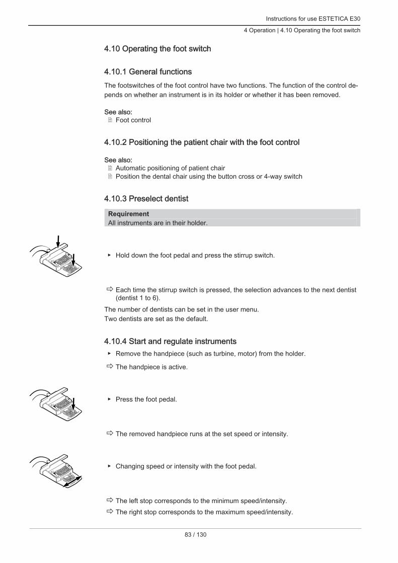
Instructions for use ESTETICA E30
4 Operation | 4.10 Operating the foot switch
4.10 Operating the foot switch
4.10.1 General functionsThe footswitches of the foot control have two functions. The function of the control de‐pends on whether an instrument is in its holder or whether it has been removed.
See also:2 Foot control
4.10.2 Positioning the patient chair with the foot control
See also:2 Automatic positioning of patient chair2 Position the dental chair using the button cross or 4-way switch
4.10.3 Preselect dentist
RequirementAll instruments are in their holder.
Hold down the foot pedal and press the stirrup switch.
ð Each time the stirrup switch is pressed, the selection advances to the next dentist(dentist 1 to 6).
The number of dentists can be set in the user menu.Two dentists are set as the default.
4.10.4 Start and regulate instruments Remove the handpiece (such as turbine, motor) from the holder.
ð The handpiece is active.
Press the foot pedal.
ð The removed handpiece runs at the set speed or intensity.
Changing speed or intensity with the foot pedal.
ð The left stop corresponds to the minimum speed/intensity.ð The right stop corresponds to the maximum speed/intensity.
83 / 130

Instructions for use ESTETICA E30
4 Operation | 4.10 Operating the foot switch
84 / 130
4.10.5 Setting the cooling condition Remove the handpiece (e.g., turbine, motor) from the holder.ð The handpiece is active.
Press "Preselected spray" footswitch.
ð The cooling status is switched each time the foot switch is pressed: spray air -spray.
ð The cooling status is displayed on the dentist and assistant element.
4.10.6 Activating blown air (optional) Remove the handpiece (such as turbine, motor) from the holder.
ð The handpiece is active.
Press the "Blown air" foot-operated button.
ð As long as the foot-operated button is pressed, blown air exits from the removedhandpiece (does not apply to PiezoLED).
4.10.7 Preselect counterclockwise motor rotation Take motor off the holder.ð The handpiece is active.
Slide the cross switch upward.
ð The direction of motor rotation is reversed each time the cross-switch is actuated:counterclockwise rotation - clockwise rotation.
ð The direction of motor rotation is displayed on the dentist element.
4.10.8 Adjusting the instrument light
Slide the cross switch to the right. (spotlight function)
ð Cold light "On" (even if Cold light "Off" is preselected).

Instructions for use ESTETICA E30
4 Operation | 4.10 Operating the foot switch
Slide the cross switch to the left.
ð Change the cold light status: "On/Off".
4.10.9 Using CONEXIOcom (fee-based additional option)
No Setting① U-shaped switch
Discard image/videoPress briefly - deletes the selected image/videoPress long - all images/videos in the clipboard are deleted
② Previous image/videoSelect previous image/video
③ Next image/videoSelect next image/video
④ Screen displayThe number of displayed images (Split View) is reduced:The live image is always shown as the last image in split view.
⑤ Screen displayThe number of displayed images (Split View) is increased: The live image is always shown as the last image in split view
⑥ Capture ModeToggles between the recording modes, video recording and image recording
⑦ Screen displayToggles between full screen and normal view
⑧ Save image/videoPress briefly - freezes the live imagePress long - saves the live image directly.If no patient is selected, the images are stored directly under "unassigned patient".
85 / 130

Instructions for use ESTETICA E30
4 Operation | 4.11 Using instruments
86 / 130
NoteIf no patient is selected, the images stay in the "Swap Tray" and are not saved per‐manently. As soon as a patient is selected, these temporary data in the "Swap Dry‐ing" are deleted. When an active patient is logged off (or a new patient is logged on)in CONEXIO, a query is shown asking whether the images shall be deleted orsaved. Data deleted at this point cannot be restored subsequently.
4.11 Using instruments
NoteConsult the pertinent separate instructions for information regarding the installation,use and servicing of the individual handpieces (such as the turbine, PIEZOsoft, Sat‐elec Mini LED, etc.).
4.11.1 Setting spray air and spray waterThe adjusting screws for spray air and spray water are situated on the underside ofthe table and correspond to the handpiece that is actually connected.For KaVo Midwest handpieces, spray air and spray water are pre-set suitable at thefactory such that no re-adjustment is required.
3
2
1
Use the short adjusting screw ② on the control valve to adjust the spray air.ð Counterclockwise rotation (seen from below) increases the flow rate. Use the long adjusting screw ① on the control valve to adjust the spray water.ð Counterclockwise rotation (seen from below) increases the flow rate.
Borden handpieces
Note In the case of Borden handpieces, the drive air needs to be adjusted for each hand‐piece by a Service Technician using adjusting screw ③. The adjustment can bemade using the measuring set Mat. no. 0.4179807 (Mat. no. 10039374) or the testmanometer for Borden handpieces Mat. no. 04118531.
4.11.2 Using suction hoses Remove the spray mist suction device and/or saliva ejector from the holder.

Instructions for use ESTETICA E30
4 Operation | 4.11 Using instruments
ð The spray mist suction device and/or saliva ejector is turned on automatically andturned off when it is replaced in the holder.
The suction flow of the saliva ejector or spray mist suction device can be reduced orblocked with the slide valves integrated in the handpieces.
5
1
2
3
4
5
6
6
Move the slide valve completely upward.ð The slide valve is open: maximum suction. Move the slide valve down all the way.ð The slide valve is closed: no suction.
NoteConnectors for the spray mist suction and the saliva ejector without slider as well asreducing pieces for the spray mistsuction are available as accessories.
Cannula holder, short, for spray mist ejector ② (Mat. no. 0.764.5783)
Cannula holder, long, for spray mist ejector ② (Mat. no. 0.764.5853)
Cannula holder, short, for saliva ejector ① (Mat. no. 0.764.5863)
Cannula adapter, reducing handpiece to 7 mm ② (Mat. no. 0.764.5873)
Cannula adapter, reducing handpiece to 11 mm ② (Mat. no. 0.764.5883)
Vacuum stop
CAUTIONDanger of backflowSwallowing or choking hazard for the patient Only actuate the vacuum stop when the suction cannula is not in the patient's
mouth.
87 / 130

Instructions for use ESTETICA E30
4 Operation | 4.11 Using instruments
88 / 130
Note Vacu-Stop is available in combination with Venturi suction, external wet suction sys‐tem, and suction valve.
When the base switch is actuated, the suction of the removed hose is stopped.
① Vacu-Stop
4.11.3 Using triple-function handpieces
CAUTIONCannulas that are worn, not screwed in or not locked into place.Injury from swallowing the cannula. Before each treatment, ensure that the cannula is properly locked or screwed into
place and firmly seated. Use original KaVo cannulas only.
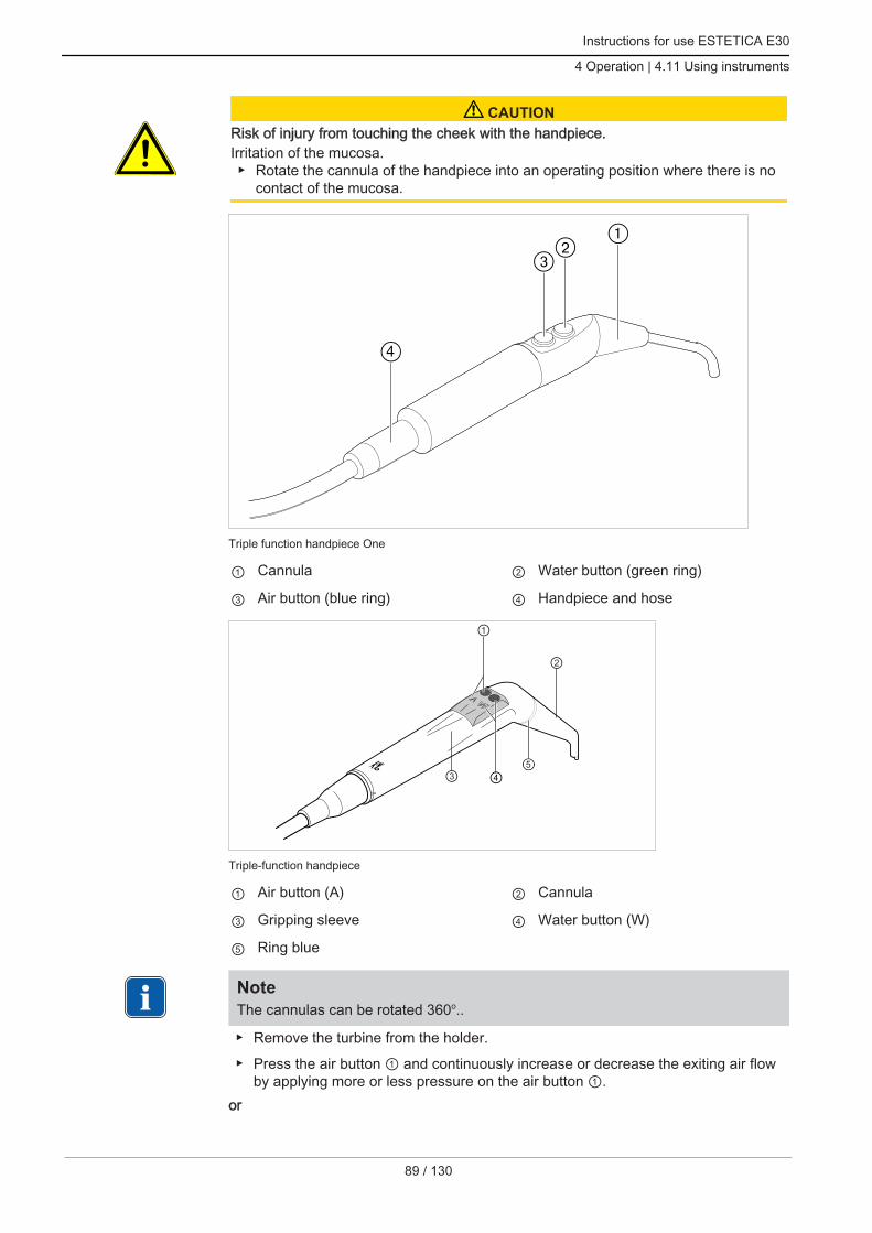
Instructions for use ESTETICA E30
4 Operation | 4.11 Using instruments
CAUTIONRisk of injury from touching the cheek with the handpiece.Irritation of the mucosa. Rotate the cannula of the handpiece into an operating position where there is no
contact of the mucosa.
Triple function handpiece One
① Cannula ② Water button (green ring)
③ Air button (blue ring) ④ Handpiece and hose
Triple-function handpiece
① Air button (A) ② Cannula
③ Gripping sleeve ④ Water button (W)
⑤ Ring blue
NoteThe cannulas can be rotated 360o..
Remove the turbine from the holder.
Press the air button ① and continuously increase or decrease the exiting air flowby applying more or less pressure on the air button ①.
or
89 / 130

Instructions for use ESTETICA E30
4 Operation | 4.11 Using instruments
90 / 130
Press the water button ④ and continuously increase or decrease the exiting waterjet by applying more or less pressure on the water button ④.
or Simultaneously press the air button ① and water button ④ and continuously in‐
crease or decrease the exiting spray by applying more or less pressure on the twobuttons.
Removing the cannulas Hold the valve body of the triple-function handpiece and screw off the cannula.
4.11.4 Using the PIEZOsoft/PiezoLED
CAUTIONHandpiece inserts can be damaged from long-term use, or when dropped or bent.They cannot be guaranteed to function properly.Injury from insert breakage. Check the handpiece inserts before each use.
CAUTIONSharp-edged tips.Risk of injury. When not in use, always keep the supplied torque wrench attached to the tip!
NotePlease comply with the enclosed "PIEZOsoft/PiezoLED" Instructions for Use.
Controlled through the menu
See also:2 4.8.5.2 PIEZOsoft/PiezoLED, Page 65
Operation with the foot control
Press the foot pedal.

Instructions for use ESTETICA E30
4 Operation | 4.12 Using the KL 703 LED in ENDO mode (optional accessory)
ð The PIEZOsoft/PiezoLED works at the pre-set intensity.
To adjust the intensity, press the foot pedal and move it to the side.
4.12 Using the KL 703 LED in ENDO mode (optional accessory)
4.12.1 General information
NoteThe endo drive can only be operated with the INTRA LUX KL 703 LED.
INTRA LUX KL 703 LED
CAUTIONUse of impermissible filing systems.Do not use impermissible filing systems which can damage the product or cause per‐sonal injury. Only use approved NiTi filing system with a conicity >2% that are suitable for rota‐
ry preparation. Only use files with shafts in conformance with DIN EN ISO 1797-1, DIN EN ISO
1797-2, DIN EN ISO 3630-1 and DIN EN ISO 3630-2 having a shaft diameter of2.334 to 2.350 mm
Follow manufacturer's instructions (mode of operation, speed, torque levels, tor‐sion resistance, etc.), and use the files according to their intended use.
CAUTIONUse of damaged files.Injury to the patient or damage to the medical device. Before preparing each root canal, insert a dental dam for safety reasons. Before each use, the files must be checked for possible signs of material fatigue,
deformation or excessive stress and if such signs appear, they must be replaced.
CAUTIONIncorrect transmission ratio.Damage from incorrect speed / incorrect torque. Only use KaVo 1:1 reducing shanks 20LH or 20LP with 1:1 INTRA LUX head L68
B (Mat. no. 1.008.1834) or 3:1 INTRA LUX head L66 BU (Mat. no. 1.008.1831).
CAUTIONExcessive torque.Injury or damage to instruments. Use root canal instruments in ENDO mode only.
91 / 130

Instructions for use ESTETICA E30
4 Operation | 4.12 Using the KL 703 LED in ENDO mode (optional accessory)
92 / 130
Technical specifications for the KL 703 LED in ENDO mode
NoteThe technical specifications apply to the KL 703 LED in ENDO mode.LED
Speed range up to 6,000 rpm
Maximal torque 2.5 Ncm
Operating mode
Note30 seconds operating time/9 minutes pause is the potential load threshold of themotor (full load at maximum speed).
In practice, pulse loads lasting seconds or pause times lasting seconds or minutes arerealistic given that the maximum possible motor current is not normally reached. Thisequates to the dentist's normal way of working.
4.12.2 Open ENDO mode Remove the endomotor INTRA LUX KL 703 LED from the holder.
Press the "Additional motor drives" key.ð The display switches to the "ENDO" menu.The device exits from Endo mode as soon as the INTRA LUX KL 703 LED endomotoris returned to the holder. The Endo mode is activated automatically once the endomo‐tor is removed, providing that the Endo mode was previously ended by putting the en‐domotor back in place.
NoteThe device does not automatically start when endo mode was left by pressing the"Motorised auxiliary drives" button, or if endo mode has never been activated sincethe last time the unit was turned on.A service technician can deactivate the automated start.
NoteBefore using the endomotor, always check the speed and transfer ratio.
S1 S2 S3 S4
Parameters ValuesTransmission factor 1:1, 3:1Parameter memory P1,P2,P3,P4,P5,P6Torque mode TQ-Ctrl, Autoreverse, AutoRev/Forw.Direction of motor rotation R, L

Instructions for use ESTETICA E30
4 Operation | 4.12 Using the KL 703 LED in ENDO mode (optional accessory)
Parameters ValuesSpeed 100 to 6,000 rpmTorque Transmission ratio 1:1: 0.15 to 2.50 Ncm
Transmission ratio 3:1: 0.4 to 8.0 Ncm
CAUTIONIncorrectly set parameters.Injury or property damage from incorrect input values. Check all input values before use.
4.12.3 Set torque modeThree different torque modes are available:
Autoreverse
Torque Control only
Autorev / Forward
Press the "Up" or "Down" key to select the desired torque mode.
ð The torque mode is shown on the display and is effective immediately.
Torque mode Torque Control only
Press the foot pedal.
ð The motor starts by rotating clockwise (if not selected otherwise).The torque is limited to the set threshold. The speed reduces until it stops dependingon the load.The direction of rotation is always to the right.A tone sounds when the set torque threshold is reached.
Push 4-way button on the foot control upward in order to switch to counterclock‐wise rotation.
Torque mode Autorev / Forward
Press the foot pedal.
ð The motor starts by rotating clockwise (if not selected otherwise)
93 / 130

Instructions for use ESTETICA E30
4 Operation | 4.12 Using the KL 703 LED in ENDO mode (optional accessory)
94 / 130
When the set torque is reached, a signal sound is emitted, and the motor switches tocounterclockwise rotation. After the set time, the motor automatically reverts to clock‐wise rotation. The time can be set in the option menu (Option 3).
See also:2 ENDO menu, Page 0
NoteThe motor's rotational direction can be reversed with the cross-switch on the foot‐switch in all torque modes.
To stop this, release the foot pedal.
Press the foot pedal.
ð The motor rotates clockwise again.
4.12.4 Changing settings in the menu
See also:2 ENDO menu (optional)
4.12.5 Leaving ENDO Mode
Press the "Additional motor drives" key.
or Place the INTRA LUX KL 703 LED back in the holder.
NoteIf the unit was switched to "Instant ENDO" mode, ENDO mode is only interruptedwhen the ENDO motor is placed in the holder, and it is continued when the ENDOmotor is removed.The function can be set by the service technician.
See also:2 Call up ENDO mode
Instructions for use ESTETICA E30
4 Operation | 4.13 Use USB interface
4.13 Use USB interface
CAUTIONElectrical power.Electrical shock. Set up the external PC outside of the patient environment keeping a minimal dis‐
tance of 1.5 m. Connect the PC and equipment connected to the PC in accordance with IEC
60601-1 / 60950.
CAUTIONElectrical power.Electrical shock from incorrectly connecting a non-medical system to the USB interfa‐ces of the device. Connect any IT device to the medical system in accordance with IEC 60601-1. Use USB devices with no additional power supply (USB-powered) only. Applied parts connected to the USB interface of the dentist element must comply
with the requisite insulation. USB-powered devices failing to meet the requisite insulation for applied parts
must be placed appropriately such that direct contact of the USB device and thepatient is excluded.
It is not permissible to touch USB-powered devices failing to meet the requisiteinsulation for applied parts and the patient at the same time.
The treatment unit may be fitted with up to three USB ports. Camera interfaces are sit‐uated on the underside of the dentist element (T-table) or in the dentist element (S-table). Only the cameras approved/enclosed in the delivery by KaVo may be connec‐ted to these interfaces.The USB port in the back is connected directly to the back-of-the-head PC (in thepresence of the corresponding wiring). USB devices meeting the specifications listedabove can be connected to this interface. To use USB devices that have been con‐nected, it may be necessary to install a suitable driver software on the back-of-the-head PC. Getting the USB ports ready for use To run an USB device, connect the USB port in the terminal box of the treatment
centre to an external back-of-the-head PC. Use one or maximally two USB exten‐sion cables 5 m (Mat. no. 1.004.6953) according to need.
USB devices connected to the dentist element must meet the USB standards,USB 1.0, 1.1 or 2.0, and consume max. 500 mA of electrical power.
4.14 Using the camera
See also:2 Instructions for Use ERGOcam One
See also:2 Instructions for Use DIAGNOcam 2170 U
4.15 Using the screen
See also:2 Instructions for use Screen One
95 / 130

Instructions for use ESTETICA E30
5 Preparation methods DIN EN ISO 17664
96 / 130
5 Preparation methods DIN EN ISO 17664
NoteThe preparation methods can be found in the care instructions.

Instructions for use ESTETICA E30
6 Accessories and kits | 6.1 Device
6 Accessories and kits
6.1 DeviceName DescriptionWater inlet block Without DVGW permit.
With water filter and pressure controller.Water bottle For a water supply for tumbler and handpieces inde‐
pendent of the public water supply.External wet suction sys‐tem with bowl valve
Suction handpieces and bowl valve are suctioned cen‐trally.
External wet suction sys‐tem, direct discharge withno bowl valve
Suction handpieces are suctioned centrally.
Venturi suction system Compressed air-operated saliva ejectorVenturi suction system Compressed air-operated spray mistOperating light KaVoLUX540 LED T / EDI / MAIA
Operating light.
Tray support For the small handpiece tray.Warm water heater Heats the tumbler water.Low-pressure regulator Regulator for suction air when the suction vacuum is too
high.Intensive germ reduction,manual
Intensive germ reduction with increased Oxygenal 6 dos‐ing
See also:2 PA ESTETICA E30
Electrical water shut-off Water pressure shut-down during off-times
6.2 Dental chairName DescriptionArmrest The armrest can be swung up to make it easier for the
patient to get in and out.Child’s seat For paediatric treatment.Trendelenburg (optional) Bench movement synchronous to backrest
6.3 Assistant unitName DescriptionSatelec Mini LED andKaVo Poly One
LED polymerisation light.
Triple-function handpieceOne / triple-function hand‐piece
Handpiece featuring air, water, no heating, and no coldlight.
6.4 Dentist elementName DescriptionAir handpiece hose For connection of turbine and SONICflex and all hand‐
pieces fitting on the multiflex coupling.
97 / 130

Instructions for use ESTETICA E30
6 Accessories and kits | 6.4 Dentist element
98 / 130
Name DescriptionBorden hose For Borden (2-hole) handpieces.Assembly kit INTRA LUXmotor KL 703 LED
Brushless motor with light.
Assembly kit INTRA LUXmotor KL 701
Brushless motor with light.
Triple function handpieceOne / triple function hand‐piece
Handpiece featuring air, water, no heating, and no coldlight.
PiezoLED Handpiece with LED light for removal of dental calculuswith Scaler tip sets.
PIEZOsoft Handpiece without light for removal of dental calculuswith tip sets, Scaler / Paro / Endo / Prep.
X-ray viewer 1440 For installation on the light mounting pole.X-ray viewer 5x5 For image size of 5 x 5 cm (install on left or right side of
dentist element).Tray holder for a standardtray / US tray / 2x-standardtray
Standard tray, US tray, and/or 2x-standard trays (installon left or right side of dentist element).
Torque control (endo) Drive for endodontic treatment.Chip blower (optional) Sets the preset blown air at the handpiece (does not ap‐
ply to PiezoLED and PIEZOsoft).Patient communication:
Screen One
DIAGNOcam 2170 U
ERGOcam One
Control of the display of previously recorded and savedimages and videos.

Instructions for use ESTETICA E30
7 Safety checks - testing instructions | 7.1 Introduction
7 Safety checks - testing instructions
7.1 Introduction
7.1.1 General instructions
Note The safety checks may only be carried out by one or more electricians (as definedin IEC 61140) who have received appropriate training for the device to be inspec‐ted.
Note The contents and specified tests in this document are based on the internationalstandard IEC 62353 (DIN VDE 0751-1). This standard applies to testing and inspec‐tions of medical electrical devices or medical electrical systems, which are definedin IEC 60601-1 (DIN EN 60601-1).
Note In order to evaluate the safety of medical devices, systems or components of medi‐cal devices or systems, the safety checks must be carried out at the times specifiedbelow: Prior to first use during servicing during inspections and maintenance following service and maintenance on the occasion of repeat testing
Note In the case of devices that have not been manufactured in accordance with IEC60601-1, (DIN EN 60601-1) these requirements can be employed taking the man‐datory safety standards for the production of these devices into consideration.
Note If the unit comprises several electrical devices or electrical devices from severalmanufacturers that are connected to a system in connection with the KaVo dentalunit, the manufacturer data contained in the instructions for use for all products sub‐ject to safety controls must also be observed.
Note Accessories to ME devices that could have an impact on the safety of the device tobe tested or the measured results must be included in the safety checks.
99 / 130

Instructions for use ESTETICA E30
7 Safety checks - testing instructions | 7.1 Introduction
100 / 130
Note All tests concerning the included safety checks of accessories must be documen‐ted.
Note Furthermore, the manufacturer data contained in the instructions for use must beadhered to in all products to be tested and inspected.
Note KaVo offers a medical device book for keeping an inventory and recording essentialmaster data on the medical device. The medical device book is only available inGerman (Mat. no. 0.789.0480).
Note The following tests and measurements must be documented, for example in themedical device book. We recommend using the templates at the end of the docu‐ment
Note The sequence of testing recommended by the manufacturer must be followed.
7.1.2 Notes for medical electrical systems
Note An ME System is the combination of individual devices (as defined by manufactur‐ers) that must meet the following conditions: At least one of these devices must be a medical electrical device. The devices must be functionally connected or at least they should be connec‐
ted by the application of a multiple socket outlet.
Note With ME systems, the person responsible for putting the system together must em‐ploy the necessary measuring parameters and measuring procedures defined inIEC 60601-1 (DIN EN 60601-1).
Note Each individual device in an ME system, which has a separate connection to thepower supply network, or which can be connected to or separated from the powersupply network without the aid of a tool, must be checked individually. Moreover,the ME system must be checked as one unit to avoid the situation, in which the „ag‐ing“ of individual devices lead to unacceptable values in sum.
Instructions for use ESTETICA E30
7 Safety checks - testing instructions | 7.1 Introduction
Note An ME system that is connected to the supply network by means of a multiple sock‐et outlet must be treated as one device during checks and testing.
Note If the ME system or part of the system is connected to the supply network by meansof a isolating transformer, the transformer must be included in the measurements.
Note In ME systems, in which more than one ME device are interconnected via data linesor otherwise, e. g. via electrically conductive attachments or coolant tubes, the earthwire resistance of every single device must be checked.
Note If it should be impossible to check single ME devices that are functionally connectedto an ME system individually for technical reasons, the ME-System must bechecked as a whole.
7.1.3 Essential parts of the safety check
Visual inspection
Optical appraisal of the safe and usable condition of the medical device and its acces‐sories.
Measurements
Measurement of the earth wire resistance in accordance with IEC 62353 (DINVDE 0751-1)
Measurement of the leakage current of the device EUL in accordance with IEC62353 (DIN VDE 0751-1)
Measurement of the leakage current of the user part EPL in accordance with IEC62353 (DIN VDE 0751-1)
Note A measurement of the isolation resistance in accordance with IEC 62353 (DIN VDE0751-1) need not be carried out. This check is covered by the measurement of theleakage current on application of a prescribed safety tester defined in IEC 62353(DIN VDE 0751-1) Annex C!
Functional test
Medical device function test as well as testing of all safety shutdowns with reference toaccompanying documentation/ instructions for use.
101 / 130
Instructions for use ESTETICA E30
7 Safety checks - testing instructions | 7.2 Instructions for safety checks
102 / 130
7.1.4 Testing intervals Check every 2 years in accordance with Type II
7.1.5 Notes on the test method in accordance with IEC 62353 Protection class 1
Type BF
The device is firmly connected / threshold: SL < 0,3 Ω
Measurement according to EUL / threshold: < 10mA*
Measurement according to EGA / threshold: < 5 mA
*The EUL threshold is compatible with the value defined in IEC 60601 (DIN EN60601), taking comment 2 from table 2 into consideration.
7.1.6 Notes on repeat testing
Note The value determined in these tests must be documented and evaluated togetherwith the measuring processes. The measured values may not overshoot the speci‐fied values.
Note Comparisons with previous measurements must be carried out if the measured val‐ues undershoot the threshold values by more than 10 %. The test intervals shouldbe reduced if a deterioration in values is determined!
7.2 Instructions for safety checks
7.2.1 Preparatory measures to be undertaken on the device
WARNINGElectrical power.Death or injury from electric shock. Before servicing, pull the mains plug out of the socket or completely disconnect
the device from the power to de-energise it! After conversion, check the electrotechnical safety in accordance with IEC 62353
(DIN VDE 0751-1).
Turn off the main switch before any servicing work.

Instructions for use ESTETICA E30
7 Safety checks - testing instructions | 7.2 Instructions for safety checks
Lift the upholstery at the foot end ① and remove from the chair.
Remove two screws ② from the cover of the junction box.
Take the cover off proceeding in upward direction.
7.2.2 Visual inspection (inspection by examination)Check the following points in advance:
Has the equipment of the ME device or the ME system been changed since thelast inspection?
Was the change documented and approved (test protocol, STK)?
Are there any indications of insufficient safety?
103 / 130

Instructions for use ESTETICA E30
7 Safety checks - testing instructions | 7.2 Instructions for safety checks
104 / 130
Check the ratings of fuses that are accessible from outside Verify whether the main fuse on the main switch ② of the unit complies with the
specified nominal data ①.
Visual inspection and appraisal of the medical device and accessories
The following list is an example and makes no claim of being complete.
Check the following items: Stability of the device
No damage to the cladding or casing (cracks, breakage)
Functioning of the carrier systems on dentist and assistant side, treatment lamp,and display (brakes, height adjustment, etc.)
Condition of the handpiece and suction hoses
Condition of all installed application parts
Condition of the control panels
Condition of the threads for the fitting of tips to the ultrasound scaler handpiece
Condition of the operating light
Absence of leaks on the body of the device
Condition of the power connection provided by the treatment centre
Condition of air and water connections
Any damage on the sight window and the casing of the camera ERGOcam
Expiry date of the water bottle inserted in the BS water bottle not exceeded
Check of legibility and completeness of the safety-related labels Check if all safety-related markings (plates and labels) are present and legible.

Instructions for use ESTETICA E30
7 Safety checks - testing instructions | 7.2 Instructions for safety checks
Check if the rating plate and serial number plates are present and legible.
ESTETICA E30 and chair nameplate
2
1
Site for affixing the rating plate and serial number plate
① Serial number plate of the chair ② Rating plate
105 / 130

Instructions for use ESTETICA E30
7 Safety checks - testing instructions | 7.2 Instructions for safety checks
106 / 130
E30 TM
E30 S
Attachment locations for serial number plate and BF labelling
Control of the availability of the necessary documents Verify whether the required instructions for use and care instructions are available
in the surgery.
Note Any irregularities determined in the visual inspection must be recorded in the testprotocol. It is essential to determine whether defects and deficiencies could have anadverse impact on the safe operation of the unit. If the determined irregularitiespresent a safety hazard and cannot be rectified directly, the unit must be closeddown until the safe operation is restored.
7.2.3 Measurements
WARNINGDanger to persons due to a lack of care exercised during the safety checks and test‐ing. Prior to connecting the treatment centre to the sight window, disconnect from the
mains supply network. Carry out all safety checks and tests in a manner that will ensure that there will be
no danger to the testing personnel, patients or other persons.
Note The safety tester must comply with the requirements defined in IEC 62353 (DINVDE 0751-1), Annex C.
Note If no other specifications have been made, all values relating to voltage and currentare effective values of alternating voltage, direct voltage or pulsating voltage res. al‐ternating current, direct current or pulsating current.

Instructions for use ESTETICA E30
7 Safety checks - testing instructions | 7.2 Instructions for safety checks
Note Cables and wires e.g. supply cables, measuring circuits and data lines must be ar‐ranged in such a manner that will ensure that their influence on measurements willbe restricted to a minimum.
Note Connection cables such as data cables and cables for the functional earth couldsimulate protective conductor connections. These types of supplementary but unin‐tentional protective earth connections could lead to erroneous measurements.
Note The following measuring aid can be ordered: KaVo measuring cable (Mat. no.0.411.8811)
Using the measuring cable ① the unit is disconnected from the mains supply and con‐nection of the treatment centre to the sight window is enabled. Hence, the customer-provided mains supply L & N on the power input board need not be disconnected. Theadapter cable ② is included in the delivery of the KaVo measuring cable and is re‐quired for older treatment centres that are not equipped with an X2 connector.
Connecting the safety tester to KaVo measuring cables on thetreatment centre
107 / 130
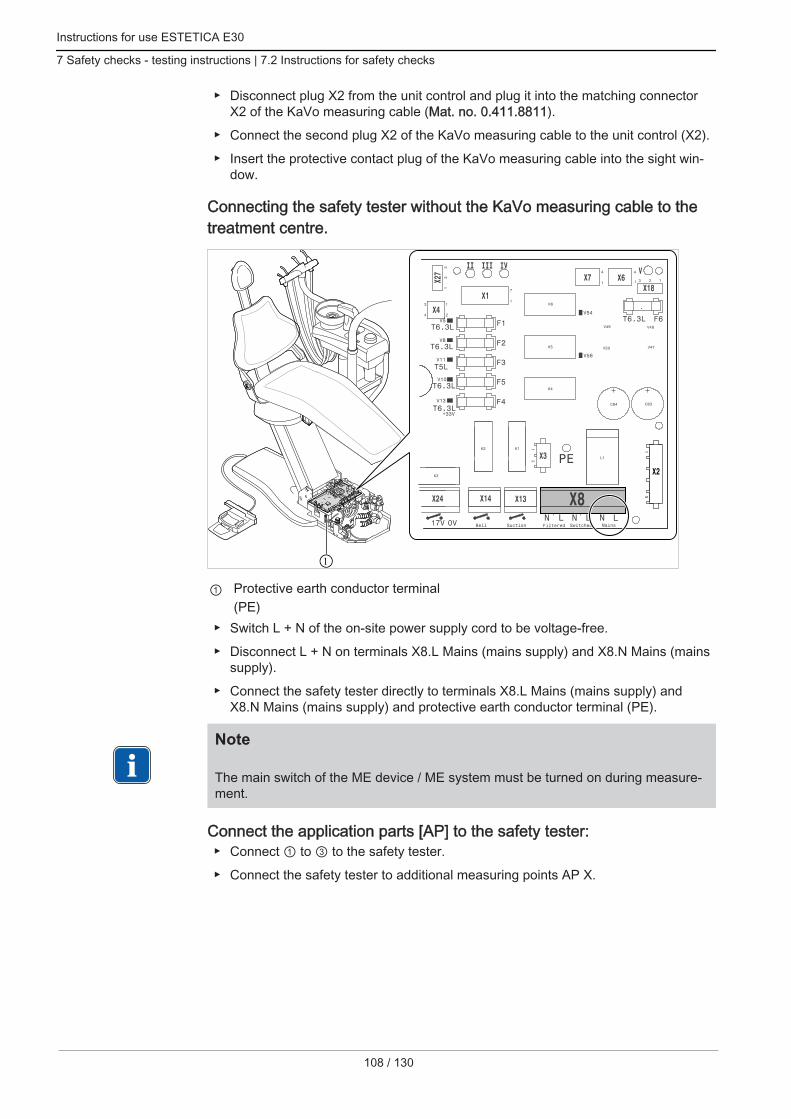
Instructions for use ESTETICA E30
7 Safety checks - testing instructions | 7.2 Instructions for safety checks
108 / 130
Disconnect plug X2 from the unit control and plug it into the matching connectorX2 of the KaVo measuring cable (Mat. no. 0.411.8811).
Connect the second plug X2 of the KaVo measuring cable to the unit control (X2).
Insert the protective contact plug of the KaVo measuring cable into the sight win‐dow.
Connecting the safety tester without the KaVo measuring cable to thetreatment centre.
1
① Protective earth conductor terminal(PE)
Switch L + N of the on-site power supply cord to be voltage-free.
Disconnect L + N on terminals X8.L Mains (mains supply) and X8.N Mains (mainssupply).
Connect the safety tester directly to terminals X8.L Mains (mains supply) andX8.N Mains (mains supply) and protective earth conductor terminal (PE).
Note The main switch of the ME device / ME system must be turned on during measure‐ment.
Connect the application parts [AP] to the safety tester: Connect ① to ③ to the safety tester.
Connect the safety tester to additional measuring points AP X.

Instructions for use ESTETICA E30
7 Safety checks - testing instructions | 7.2 Instructions for safety checks
Note Additional measuring points AP X must be taken into consideration in the presenceof accessories: e.g. accessories such as PIEZO ultrasound scaler, HF surgery etc.
See also:2 Annex - Additional measuring points, Page 0
Connect accessible conductive parts [ACP] with PE
ACP = accessible conductive parts
ACP
ACP
Note Additional measuring points ACP X must be taken into consideration in the pres‐ence of accessories: e.g. accessories such as saline pump etc.
See also:2 Annex - Additional measuring points, Page 0
ACPs on the treatment centreNo ACPs need to be connected to the protective conductor (PE) during the measure‐ment on the treatment unit ESTETICA E30, as all relevant parts are connected to thePE and included in the test before they leave the factory.
109 / 130

Instructions for use ESTETICA E30
7 Safety checks - testing instructions | 7.2 Instructions for safety checks
110 / 130
ACPs on treatment lampsNo ACPs need to be connected to the treatment lights during the measurement withthe protective conductor (PE) because all relevant parts have already been connectedwith the protective conductor (PE) in the factory and are included in the test.
Measure protective conductor resistance
Threshold: < 0,3 Ω (maximum value!)
Note The integrity of the power supply cable, in particular the protective earth wire of thepower cable must be ensured. As this is a fixed installation, the evaulation can beconducted by means of a visual inspection. If damage is determined, the furtherprocedure to be taken is specified in the general instructions.
Note In this measurement the resistance of the protective earth connection of the supplynetwork can be taken into consideration.
Note If applicable: all removable supply connection lines, which are retained for use,should be taken into consideration and the respective PE measured.
Protective earth measurement
The protective conductor resistance must be measured at the following parts of thedevice: Treatment centre
Treatment lamp
Accessories
Note Additional measuring points SL X need to be taken into consideration in the pres‐ence of accessories: e.g. if accessories are connected, connection to external devi‐ces, camera module of the multimedia system, etc.
See also:2 Annex - Additional measuring points, Page 0

Instructions for use ESTETICA E30
7 Safety checks - testing instructions | 7.2 Instructions for safety checks
Scan the treatment centre with the test tip
Measuring points on the device base
① Surroundings of the protective earthconductor terminal
② Main switch holding plate
③ Stand cover base plate ④ Top part of the chair
⑤ Foot control floor plate (bottom side)
111 / 130
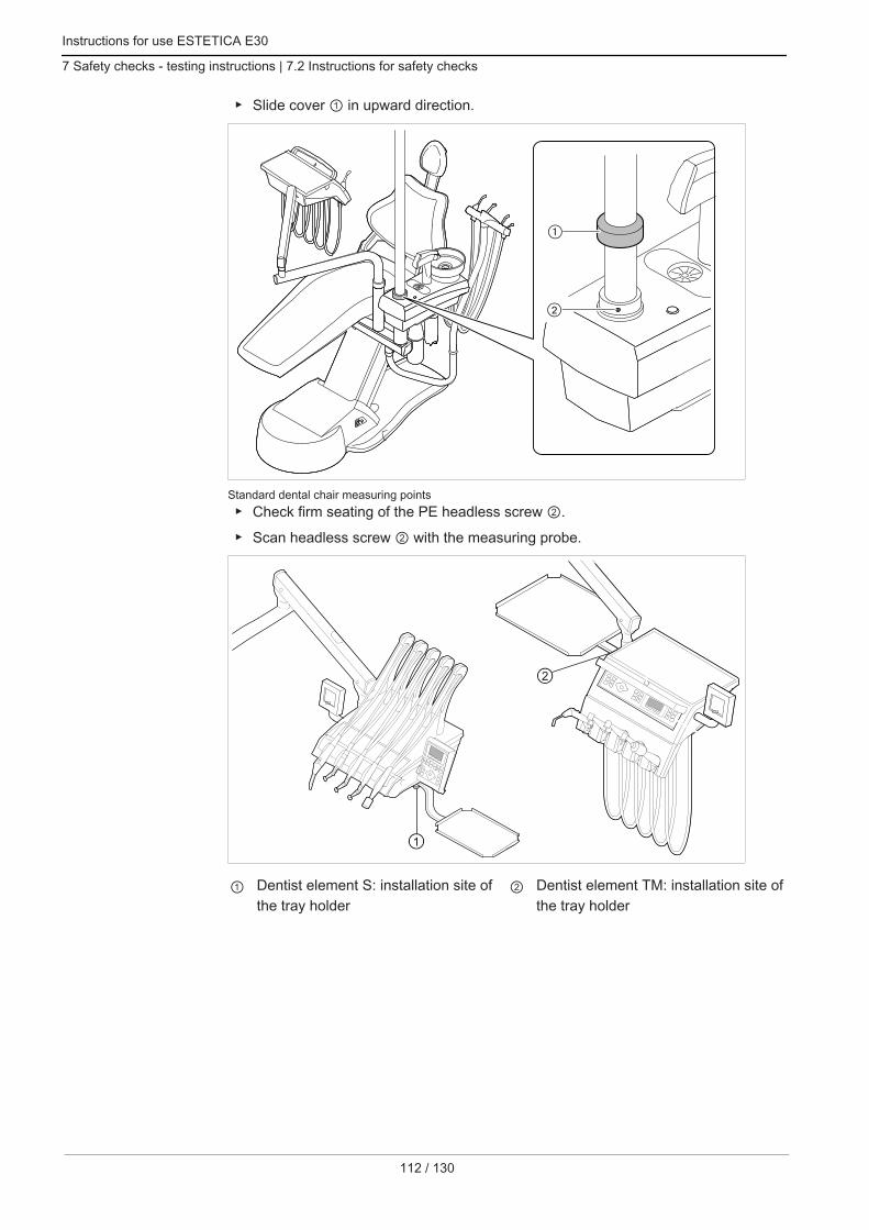
Instructions for use ESTETICA E30
7 Safety checks - testing instructions | 7.2 Instructions for safety checks
112 / 130
Slide cover ① in upward direction.
Standard dental chair measuring points Check firm seating of the PE headless screw ②.
Scan headless screw ② with the measuring probe.
① Dentist element S: installation site ofthe tray holder
② Dentist element TM: installation site ofthe tray holder

Instructions for use ESTETICA E30
7 Safety checks - testing instructions | 7.2 Instructions for safety checks
① Assistant element: fastening screw onbottom side of assistant element
Scan the treatment lamp with the test tip
Operating light KaVoLUX 540 LED U
① Fastening screw of the handle supportwhen the gripping sleeve has been re‐moved
Operating light EDI/MAIANo measuring points need to be scanned on the operating lights EDI and MAIA.
Touch monitor with test tip
113 / 130

Instructions for use ESTETICA E30
7 Safety checks - testing instructions | 7.2 Instructions for safety checks
114 / 130
Touch measuring point ① with the test tip.or Sample the measuring point ② after removing the display cover.
Measure protective conductor resistance of accessories
See also:2 Annex - Additional measuring points, Page 0
Measure equivalent unit leakage current
Threshold: < 10 mA (maximum value!)
ACP
Protection class 1
WARNINGElectrical power.Death or injury from electric shock. Conduct test for leakage current in devices of Protection Class 1 only after the
protective earth test has been passed.
WARNINGElectrical power.Death or injury from electric shock. Prior to connecting the treatment centre to the sight window, disconnect the treat‐
ment unit from the mains supply network.
Measure equivalent patient leakage current
Threshold: < 5 mA (maximum )

Instructions for use ESTETICA E30
7 Safety checks - testing instructions | 7.2 Instructions for safety checks
ACP
Protection class 1
WARNINGElectrical power.Death or injury from electric shock. Conduct test for leakage current in devices of Protection Class 1 only after the
protective earth test has been passed.
WARNINGElectrical power.Death or injury from electric shock. Prior to connecting the treatment centre to the sight window, disconnect the treat‐
ment unit from the mains supply network.
Note In the testing of ME devices with several application parts, the parts must be con‐nected in succession. The measured results must be evaluated using the thresholdvalues. Application parts, which are not included in the measurement, remain open.
Note An additional measurement of the leakage current from type B application partsneed only be carried out if this is specified by the manufacturer (see accompanyingdocuments).
Note A separate measurement is not usually required for type B application parts. Theapplication parts are connected to the casing (see diagram) and included in themeasurement of the leakage current of the casing, whereby the same reliable val‐ues are applicable.
7.2.4 Functional testThe following conditions must be fulfilled in all function tests:
The basic function of the treatment centre must be guaranteed.
The treatment centre must be fit for use.
It must not exhibit any irregularities, noise or abrasion etc.
The following list is an example and makes no claim of being complete. Function test of the safety circuits (see diagram below)
Functioning of the master switch of the device
Functioning of the displays
115 / 130
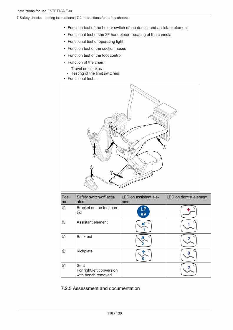
Instructions for use ESTETICA E30
7 Safety checks - testing instructions | 7.2 Instructions for safety checks
116 / 130
Function test of the holder switch of the dentist and assistant element
Functional test of the 3F handpiece – seating of the cannula
Functional test of operating light
Function test of the suction hoses
Function test of the foot control
Function of the chair:- Travel on all axes- Testing of the limit switches
Functional test ...
5
Pos.no.
Safety switch-off actu‐ated
LED on assistant ele‐ment
LED on dentist element
① Bracket on the foot con‐trol
② Assistant element
③ Backrest
④ Kickplate
⑤ SeatFor right/left conversionwith bench removed
7.2.5 Assessment and documentation

Instructions for use ESTETICA E30
7 Safety checks - testing instructions | 7.2 Instructions for safety checks
Note All tests conducted must be documented comprehensively. The documents mustcontain at least the following particulars: Name of the test centre Name of the test engineer Name of the tested device (e. g. type, serial number) Tests and measurements Data, type and measured results of the visual inspections Data, type and measured results Data, type and measured results of function tests Measuring/test equipment including SN/test equipment number and calibration
period Final evaluation Name, date and signature of test engineer
There is a copy of a test report template at the end of chapter STK. KaVo recom‐mends the use of this template.
Note Following testing, maintenance or adjustment, it must be verified whether the MEdevice or ME system has been restored to the state that is required for the intendedusage before it is employed once again.
NoteIf the safety of the tested ME device or ME system has not been established, e.g.the tests have not been completed with positive results, the device or system mustbe marked accordingly and the potential hazard emanating from the device or sys‐tem must be communicated in writing to the RESPONSIBLE ORGANISATION (tothe operator, as a rule). This action is not required if the cause of the malfunctioncould be determined and rectified. The defect must be recorded in the protocol.
117 / 130

Instructions for use ESTETICA E30
7 Safety checks - testing instructions | 7.2 Instructions for safety checks
118 / 130
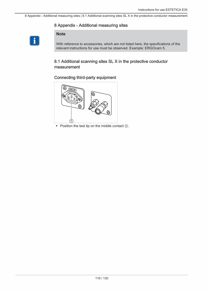
Instructions for use ESTETICA E30
8 Appendix - Additional measuring sites | 8.1 Additional scanning sites SL X in the protective conductor measurement
8 Appendix - Additional measuring sites
Note With reference to accessories, which are not listed here, the specifications of therelevant instructions for use must be observed. Example: ERGOcam 5.
8.1 Additional scanning sites SL X in the protective conductormeasurement
Connecting third-party equipment
Position the test tip on the middle contact ①.
119 / 130

Instructions for use ESTETICA E30
8 Appendix - Additional measuring sites | 8.1 Additional scanning sites SL X in the protective conductor measurement
120 / 130
Ceiling adapter for operating light assembly kit
2
3
① Base plate for the ceiling adapter ② Surroundings of the protective con‐ductor connector
③ Surroundings of the protective earthconductor terminal
Touch monitor with test tip
Touch measuring point ① with the test tip.or

Instructions for use ESTETICA E30
8 Appendix - Additional measuring sites | 8.2 Additional measuring sites AP X for EUL/EPL measurement
Sample the measuring point ② after removing the display cover.
8.2 Additional measuring sites AP X for EUL/EPL measurement
Scan the PIEZO ultrasonic scaler with test probe
1
Exemplary presentation of the measuring point on the PiezoLED ultrasonic scaler
① Test probe on ultrasonic scaler tip inultrasonic scaler handpiece
121 / 130

Instructions for use ESTETICA E30
9 Troubleshooting
122 / 130
9 Troubleshooting
NoteIn case of malfunctions of the individual handpieces (e.g. turbine, motor, camera,Satelec, Mini LED etc.), consult the separate instructions for the use and care of theindividual instruments.
Malfunction Cause Remedy
Nothing works. Main switch is off. Turn on the main switch.
Main service fuse interrup‐ted the electric circuit.
Unplug the unit from the mains.
Check and replace, if required, the main servicefuse.
The main service fuse is situated next to the mas‐ter switch.
For this purpose, open the bayonet closure with ascrewdriver and replace the fine-wire fuse (T 6.3 HMat. no. 0.223.2783).
The re-close the bayonet closure with the screw‐driver.
The patient chair does notmove.
The safety shutoff is acti‐vated.(The LED on the controlpanel flashes.)
Check the safety shutoff and eliminate the reasonfor the shutoff.
Display without indicator. Bus / hardware error. Turn the device off and on.
Call the service technician to look into the problemif it continues to exist.
Operating device no func‐tion.
Bus / hardware error. Turn the device off and on.
Call the service technician to look into the problemif it continues to exist.
Turbine making loud run‐ning noises.
Turbine wheel faulty. Replace turbine wheels. Follow the operating instructions for the turbine.
Satelec Mini LED / KaVoPoly One does not work.
Also refer to: Instructionsfor Use of the Satelec MiniLED / KaVo Poly One
No cold light on the hand‐pieces.
Cold light not preselected. Preselect cold light.
The high-pressure lamp orMulti LED on the hand‐piece is defective.
Replace the high-pressure lamp or Multi LED. Also refer to: Instructions for Use of the handpiece
See also:2 Instructions for Use of the handpiece
No spray in the handpie‐ces.
No spray preselected. Preselect spray. Check setting on butterfly valves of the dentist ele‐
ment.

Instructions for use ESTETICA E30
9 Troubleshooting
Malfunction Cause Remedy
Close the ring for control‐ling the spray on the hand‐pieces.Spray throttle Ws20 con‐nected to control valve.
Open the ring for controlling the spray on the hand‐pieces.
Check setting on butterfly valves of the dentist ele‐ment.
The main water valve inthe office is closed.
Open main valve.
The compressor is notturned on.
Turn on the compressor.
No water in the tumblerand spittoon bowl
Water bottle is empty. Fill the water bottle.
No air pressure in the unit. Turn on the compressor.
Spray at the instruments isinsufficient.
The spray nozzles aredirty/clogged.
Clean the spray nozzles according to the accom‐panying instrument operating instructions.
Leaks in instruments. O-rings at MULTIflex ormotor coupling, grippingsleeve or cannula of the tri‐ple-function handpiece aredamaged.
Replace O-rings.
PiezoLED or PIEZOsoftwithout function.
PiezoLED or PIEZOsoftnot pivoting.
Also refer to: Instructions for Use of the PIEZOsoft/PiezoLED
The suction hoses do nothave any suction.
Slides on the conical sec‐tions are closed.
Open the slide valve.
Sieves in suction connec‐tor are blocked.
Replace sieves.
Base plate for vacu-stophas been activated.
Relieve base plate.
Suction machine not run‐ning.
Turn on the suction machine.
Check the suction machine fuse.
Water in the return air fil‐ter.
O-rings of the MULTIflexcoupling are damaged.
Replace all O-rings of the MULTIflex coupling.
The operating light cannotbe switched on.
Switch on the lamp head isswitched off.
Turn on the switch.
ERGOcam/DIAGNOcamdoes not work.
PC is switched off. Turn on the computer.
USB cable too long. Make sure that the cable length does not exceed10 m (2 x 5 m passive with repeater).
No data transmission tothe multimedia menu of theunit.
No or faulty ethernet con‐nection between dentalunit and office network.
Notify network administrator.
123 / 130

Instructions for use ESTETICA E30
9 Troubleshooting
124 / 130
Malfunction Cause Remedy
Camera images shows im‐ages only as black/whiteimages.
Electrical or electromag‐netic interference by otherequipment.
Restart the CONEXIO PC.
Camera image freezeswithout the release buttonor foot control having beentriggered. Camera imagefails to return to live imagemode.
Electrical or electromag‐netic interference by otherequipment.
Replace the camera in the holder and then take itout again.
Camera image freezeswithout the release buttonor foot control having beentriggered. Taking the cam‐era out again did not solvethe problem.
Electrical or electromag‐netic interference by otherequipment.
Restart the software.
Camera image freezeswithout the release buttonor foot control having beentriggered. The monitorturns itself off.
Electrical or electromag‐netic interference by otherequipment.
Restart the treatment unit and the CONEXIO PC.
An acoustic signal is is‐sued every second.
Leaking water switch rec‐ognises leaking water.
Remove water from the unit body. If necessary,have a technician fixed the leak.

Instructions for use ESTETICA E30
10 Information about electromagnetic compatibility in accordance with EN60601-1-2 | 10.1 Electromagnetic Transmissions
10 Information about electromagnetic compatibility in accordance withEN60601-1-2
10.1 Electromagnetic TransmissionsThe ESTETICA E30 treatment unit is for use in an environment like the one cited be‐low. The customer or user of the ESTETICA E30 should ensure that it is used in thecorrect environment.
Measurements of emitted interfer‐ence
Conformance Electromagnetic environment -Guidelines
HF emissions according to CISPR11
Group 1 The ESTETICA E30 device uses HFenergy for its internal functions ex‐clusively. Therefore, the HF emis‐sion of the device is very low and in‐terference with adjacent electronicdevices is unlikely.
HF emissions according to CISPR11
Class B The ESTETICA E30 device is suita‐ble for use in all facilities includingresidential ones, and facilities thatare directly connected to a publicpower supply that also supplies resi‐dential buildings.
Emission of harmonics according toEN 61000-3-2
Class A The ESTETICA E30 device is suita‐ble for use in all facilities includingresidential ones, and facilities thatare directly connected to a publicpower supply that also supplies resi‐dential buildings.
Emission of voltage fluctuations/flicker according to EN 61000-3-3
Conforms The ESTETICA E30 device is suita‐ble for use in all facilities includingresidential ones, and facilities thatare directly connected to a publicpower supply that also supplies resi‐dential buildings.
10.2 Resistance to electromagnetic interferenceThe ESTETICA E30 treatment unit is for use in an environment like the one cited be‐low. The customer or user of the ESTETICA E30 should ensure that it is used in thecorrect environment.
Interference immunity tests EN 60601 test level Compliance level Electromagnetic environ‐ment - Guidelines
Electrostatic discharge(ESD) according to EN61000-4-2
± 6 kV contact discharge± 8 kV atmospheric dis‐charge
± 2/4/6 kV contact dis‐charge± 2/4/8 kV atmosphericdischarge
Floors should be made ofwood or concrete or be fit‐ted with ceramic tiles. If thefloor is fitted with syntheticmaterial, the relative hu‐midity must be at least30%.
Fast transient electrical in‐terference / bursts accord‐ing to EN 61000-4-4
± 2 kV for power lines± 1 kV for input and outputlines
± 2 kV for power lines The quality of the supplyvoltage should correspondto that of a typical businessor hospital environment.
125 / 130

Instructions for use ESTETICA E30
10 Information about electromagnetic compatibility in accordance with EN60601-1-2 | 10.3 Recommended safe distance be‐tween portable and mobile HF telecommunications equipment and the treatment unit
126 / 130
Interference immunity tests EN 60601 test level Compliance level Electromagnetic environ‐ment - Guidelines
Surges according to EN61000-4-5
± 1 kV push-pull voltage± 2 kV common mode volt‐age
± 1 kV push-pull voltage± 2 kV common mode volt‐age
The quality of the supplyvoltage should correspondto that of a typical businessor hospital environment.
Voltage interruptions,short-term interruptionsand fluctuations of the sup‐ply voltage according toEN 61000-4-11
< 5% UT(> 95% interruption)for ½ period40 % UT(60% interruption)for 5 periods70 % UT(30% interruption)for 25 periods< 5% UT(> 95% interruption)for 5 s(250 periods)
< 5% UT(> 95% interruption)for ½ period40 % UT(60% interruption)for 5 periods70 % UT(30% interruption)for 25 periods< 5% UT(> 95% interruption)for 5 s(250 periods)
The quality of the supplyvoltage should correspondto that of a typical businessor hospital environment. Ifthe user needs the ESTE‐TICA E30 to work even ifthe power supply is inter‐rupted, we recommendsupplying energy to theESTETICA E30 from anuninterruptible power sup‐ply or battery.
Magnetic field at a supplyfrequency (50/60 Hz) ac‐cording to EN 61000-4-8
3 A/m 3 A/m Magnetic fields at themains frequency shouldcorrespond to typical val‐ues in a business andhospital environment.
NOTE: V T is the alternating mains voltage before the test level is used.
10.3 Recommended safe distance between portable and mobile HFtelecommunications equipment and the treatment unitThe ESTETICA E30 is intended for use in an electromagnetic environment in whichthe HF interference parameters are controlled. The customer or user of the ESTETICAE30 can help prevent electromagnetic interference by maintaining the minimum clear‐ance between portable and mobile HF telecommunication devices (transmitters) andthe ESTETICA E30 depending on the output of the communication device as indicatedbelow.Safe distance depending on the transmission frequency:
Rated power of the trans‐mitter in W
150 kHz to 80 MHzd=1.17 P m
80 MHz to 800 MHzd=1.17 P m
800 MHz to 2.5 GHzd=2.33 P m
0.01 0.1 0.1 0.20.1 0.4 0.4 0.71 1.2 1.2 2.310 3.7 3.7 7.4100 11.7 11.7 23.3
For transmitters whose maximum rated power is not in the above table, the recom‐mended safe distance d in meters (m) can be calculated using the equation for the re‐spective gap, where P is the maximum rated power of the transmitter in Watts (W) ac‐cording to the manufacturer's information.NOTE 1: At 80 MHz and 800 MHz, the higher frequency range applies.NOTE 2: These guidelines may not be applicable in every case. The spread of electro‐magnetic waves is absorbed and reflected by buildings, objects and people.

Instructions for use ESTETICA E30
10 Information about electromagnetic compatibility in accordance with EN60601-1-2 | 10.4 Immunity to electromagnetic in‐terference
10.4 Immunity to electromagnetic interferenceThe treatment unitESTETICA E30 is designed for operation in an environment asspecified below. The customer or user of the ESTETICA E30 should make sure thatthe device is used in an environment of the specified type.
Interference immunitytests
EN 60601 test level Compliance level Electromagnetic environment -Guidelines
Wire-based HF interfer‐ence according to EN61000-4-6Wireless HF interfer‐ence according to EN61000-4-3
3 Veff150 kHz to 80 MHzoutside the ISM bandsa
V/m80 MHz to 2.5 GHz
3 Veff3 V/m
Handheld and mobile wireless devi‐ces should not be used at a shorterdistance from theESTETICA E30 in‐cluding cables than the recommen‐ded safe clearance calculated usingthe appropriate equation for theemission frequency.Recommended safe distance:d = 1.17 P
d= 1.17 P for 80 MHz to 800 MHzd= 2.33 P for 800 MHz to 2.5 GHzwhere P is the maximal nominalpower of the transmitter in watts(W) as specified by the transmittermanufacturer and d is the recom‐mended safe clearance in metres(m).bThe field strength of stationarywireless radio transmitters as meas‐ured locallycshould be lower thanthe conformance level at all fre‐quencies.dInterference is possible in the vicin‐ity of devices bearing the followingicon.
NOTE 1: At 80 MHz and 800 MHz, the higher frequency range applies.NOTE 2: These guidelines may not be applicable in every case. The spread of electro‐magnetic waves is absorbed and reflected by buildings, objects and people.aThe ISM frequency bands (for industrial, scientific, and medical applications) between150 kHZ and 80 MHz are 6.765 MHz to 6.795 MHz; 13.553 MHz to 13.567 MHz;26.957 MHz to 27.283 MHz, and 40.66 MHz to 40.70 MHz.bThe compliance levels in the ISM frequency bands between 150 kHz and 80 MHzand in the frequency range from 80 MHz to 2.5 GHz are intended to reduce the proba‐bility of mobile/handheld communications facilities causing interference when they areinadvertently introduced into the patient area. For this reason, the additional factor of10/3 is applied in the calculation of the recommended safe clearances in these rangesof frequencies.cThe field strength of stationary transmitters, such as, e.g. base stations of mobilephones and mobile terrestrial radio devices, amateur radio stations, AM and FM radioand television transmitters, cannot be determined exactly based on theoretical consid‐erations. A site study should be considered to determine the electromagnetic environ‐ment in terms of stationary transmitters. If the measured field strength at the site, atwhich the ESTETICA E30 is used, exceeds the compliance levels shown above, theESTETICA E30 should be monitored to demonstrate proper function. If any uncom‐
127 / 130

Instructions for use ESTETICA E30
10 Information about electromagnetic compatibility in accordance with EN60601-1-2 | 10.4 Immunity to electromagnetic in‐terference
128 / 130
mon performance characteristics are observed, additional measures may be required,such as, e.g., changing the orientation or using a different location for the ESTETICAE30.d In the frequency range of 150 kHz to 80 MHz, the field strength should be less than3V eff V/m.


1.00
9.52
95 ·
Fk ·
2015
1102
- 5
· en