INSTRUCTIONS FOR THE DENTIST - Straumann · INSTRUCTIONS FOR THE DENTIST ... (Art. No. 048.350). In...
16
INSTRUCTIONS FOR THE DENTIST synOcta ® impression procedure, „Screw-retained“ and „Snap-on“ 1. Attach synOcta ® Impression caps to implants. Hand-tighten screws. 3. Undo the screws and remove the impression. 1. Attach impression caps to the implants. The cap has engaged when a “click” is heard. If the cap is correctly seated, it can be turned on the implant. 2. The octagon of the synOcta ® Positioning cylinder must be aligned with the octagon of the implant and inserted into the impression cap up to the limit stop. 4. Sending the impression to the dental lab. 5. Screw the synOcta ® Analog to the impression caps hand-tight. 3. Take the impression with elastomer impression materials (vinyl polysiloxane or polyether rubber). 4. Sending the impression to the dental lab. 5. Replace synOcta ® Analogs into the impression. The shoulder must engage audibly. Make the working model from special hard plaster, Type 4 (DIN 13911). Note: The impression-taking method is identical for implant shoulder Ø 4.8 mm RN and implant shoulder Ø 6.5 mm WN. 2. Take the impression with a special tray with perforations for screws and elastomer impression matieral (vinyl polysiloxane or polyether rubber). Snap-on (Closed tray) Screw-retained (Open tray) “click”
Transcript of INSTRUCTIONS FOR THE DENTIST - Straumann · INSTRUCTIONS FOR THE DENTIST ... (Art. No. 048.350). In...
INSTRUCTIONS FOR THE DENTIST
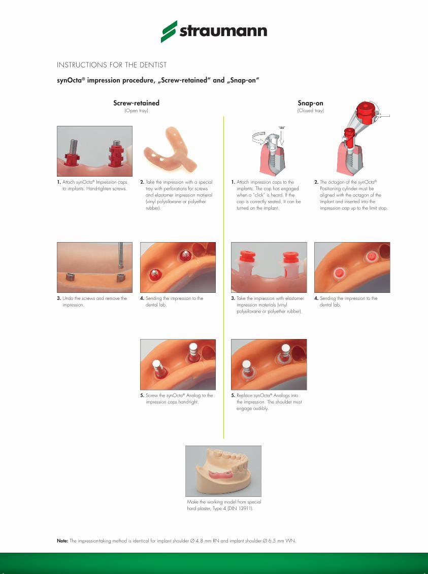
synOcta® impression procedure, „Screw-retained“ and „Snap-on“
1. Attach synOcta® Impression caps to implants. Hand-tighten screws.
3. Undo the screws and remove the impression.
1. Attach impression caps to the implants. The cap has engaged when a “click” is heard. If the cap is correctly seated, it can be turned on the implant.
2. The octagon of the synOcta® Positioning cylinder must be aligned with the octagon of the implant and inserted into the impression cap up to the limit stop.
4. Sending the impression to the dental lab.
5. Screw the synOcta® Analog to the impression caps hand-tight.
3. Take the impression with elastomer impression materials (vinyl polysiloxane or polyether rubber).
4. Sending the impression to the dental lab.
5. Replace synOcta® Analogs into the impression. The shoulder must engage audibly.
Make the working model from special hard plaster, Type 4 (DIN 13911).
Note: The impression-taking method is identical for implant shoulder Ø 4.8 mm RN and implant shoulder Ø 6.5 mm WN.
2. Take the impression with a special tray with perforations for screws and elastomer impression matieral (vinyl polysiloxane or polyether rubber).
Snap-on(Closed tray)
Screw-retained(Open tray)
“click”

RN = Regular NeckWN = Wide Neck
Art. No. Article Dimensions Material
Components for synOcta® impressions
048.017V4 RN impression cap, snap-on height 8 mm plastic
048.070V4 RN synOcta® positioning cylinder, red, snap-on height 12 mm plastic
048.010 RN synOcta® impression cap, screw-retained, red, with integral guide screw
height 10.1 mm anodized aluminium/titanium
048.090 RN synOcta® impression cap, built-in handle, red, with integral guide screw
height 21 mm anodized aluminium/titanium
048.013 WN impression cap, snap-on height 8 mm plastic
048.095 WN synOcta® positioning cylinder, white, snap-on height 12 mm plastic
048.091 WN synOcta® impression cap, screw-retained, with integral guide screw
height 10 mm aluminium/titanium
synOcta® Master cast fabrication
048.124 RN synOcta® analog, gray (with red stripe) length 12 mm stainless steel
048.171 WN synOcta analog, gray length 12 mm stainless steel
Prosthetic Instruments
046.400 SCS Screwdriver, extra short length 15 mm stainless steel
046.401 SCS Screwdriver, short length 21 mm stainless steel
046.402 SCS Screwdriver, long length 27 mm stainless steel
046.410 SCS Screwdriver, extra short, for handpiece adapter length 20 mm stainless steel
046.411 SCS Screwdriver, short, for handpiece adapter length 26 mm stainless steel
046.412 SCS Screwdriver, long, for handpiece adapter length 32 mm stainless steel
Caution: The plastic parts are intended for single use only. They must not be sterilized. To avoid damage (loss of elasticity, embrittlement) to the plastic parts, they must be protected from exposure to strong light or heat.
For detailed information, refer to our brochure “Crown and Bridge Restorations with the synOcta® Prosthetic System”, Art. No. 152.255.
01/08 152.259/e
INSTRUCTIONS FOR THE DENTIST
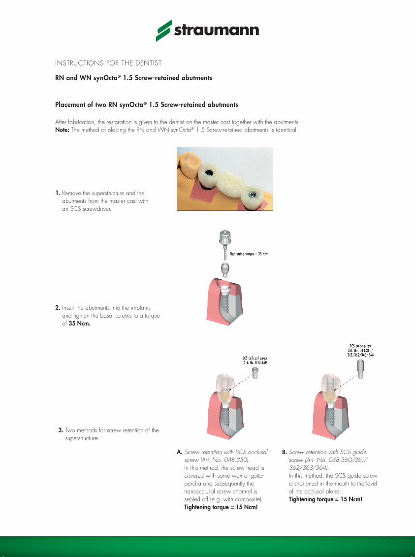
RN and WN synOcta® 1.5 Screw-retained abutments
Placement of two RN synOcta® 1.5 Screw-retained abutments
After fabrication, the restoration is given to the dentist on the master cast together with the abutments.Note: The method of placing the RN and WN synOcta® 1.5 Screw-retained abutments is identical.
1. Remove the superstructure and the abutments from the master cast with an SCS screwdriver.
A. Screw retention with SCS occlusal screw (Art. No. 048.350). In this method, the screw head is covered with some wax or gutta-percha and subsequently the transocclusal screw channel is sealed off (e.g. with composite). Tightening torque = 15 Ncm!
2. Insert the abutments into the implants and tighten the basal screws to a torque of 35 Ncm.
3. Two methods for screw retention of the superstructure:
B. Screw retention with SCS guide screw (Art. No. 048.360/361/ 362/363/364). In this method, the SCS guide screw is shortened in the mouth to the level of the occlusal plane. Tightening torque = 15 Ncm!
RN = Regular NeckWN = Wide Neck
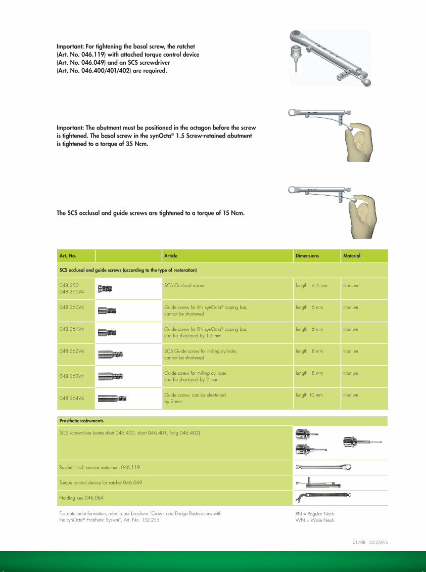
Art. No. Article Dimensions Material
SCS occlusal and guide screws (according to the type of restoration)
048.350048.350V4
SCS Occlusal screw length 4.4 mm titanium
048.360V4 Guide screw for RN synOcta® coping bar, cannot be shortened
length 6 mm titanium
048.361V4 Guide screw for RN synOcta® coping bar, can be shortened by 1.6 mm
length 6 mm titanium
048.362V4 SCS Guide screw for milling cylinder, cannot be shortened
length 8 mm titanium
048.363V4Guide screw for milling cylinder, can be shortened by 2 mm
length 8 mm titanium
048.364V4Guide screw, can be shortened by 2 mm
length 10 mm titanium
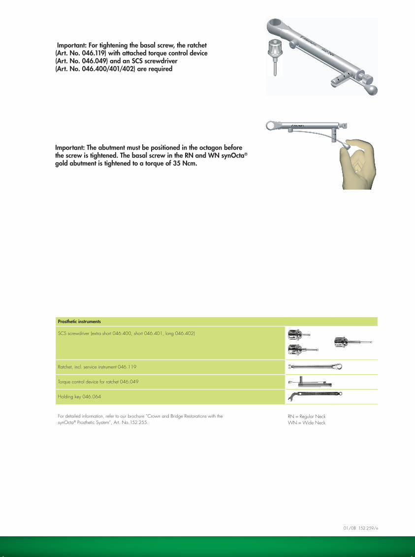
Important: For tightening the basal screw, the ratchet (Art. No. 046.119) with attached torque control device (Art. No. 046.049) and an SCS screwdriver(Art. No. 046.400/401/402) are required.
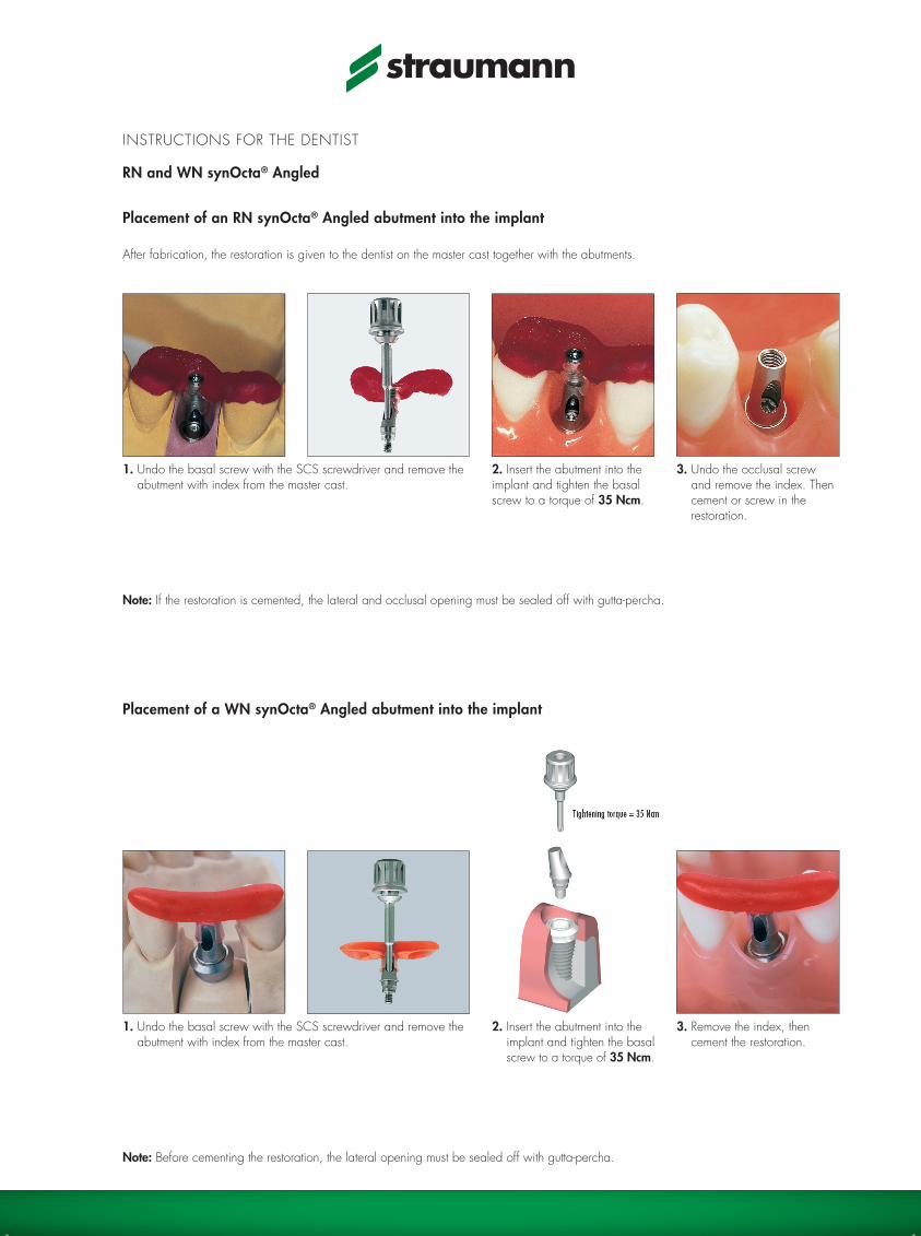
Important: The abutment must be positioned in the octagon before the screw is tightened. The basal screw in the synOcta® 1.5 Screw-retained abutment is tightened to a torque of 35 Ncm.
The SCS occlusal and guide screws are tightened to a torque of 15 Ncm.
Prosthetic instruments
SCS screwdriver (extra short 046.400, short 046.401, long 046.402)
Ratchet, incl. service instrument 046.119
Torque control device for ratchet 046.049
Holding key 046.064
For detailed information, refer to our brochure “Crown and Bridge Restorations with the synOcta® Prosthetic System”, Art. No. 152.255.
01/08 152.259/e

INSTRUCTIONS FOR THE DENTIST
RN and WN synOcta® gold abutment
RN and WN synOcta® gold abutment – placement of the final restoration
NoteThe method of placing the RN and WN synOcta® gold abutment is identical.
1. Align the octagon of the customized gold abutment on the octagon of the implant and insert the meso-structure into the implant. Tighten the basal screw with a force of 35 Ncm.
2. Then seal off the screw channel with gutta-percha, and finally cement the crown onto the mesostructure.
RN = Regular NeckWN = Wide Neck
Important: For tightening the basal screw, the ratchet (Art. No. 046.119) with attached torque control device (Art. No. 046.049) and an SCS screwdriver (Art. No. 046.400/401/402) are required
Important: The abutment must be positioned in the octagon before the screw is tightened. The basal screw in the RN and WN synOcta® gold abutment is tightened to a torque of 35 Ncm.
Prosthetic instruments
SCS screwdriver (extra short 046.400, short 046.401, long 046.402)
Ratchet, incl. service instrument 046.119
Torque control device for ratchet 046.049
Holding key 046.064
For detailed information, refer to our brochure “Crown and Bridge Restorations with the synOcta® Prosthetic System”, Art. No.152.255.
01/08 152.259/e

INSTRUCTIONS FOR THE DENTIST
RN and WN synOcta® Cement retained
Placement of two RN synOcta® Cement retained abutments in implants
After fabrication, the restoration is given to the dentist on the master cast together with the abutments.
Note
The method of placing the RN and WN synOcta® cement-retained abutments is identical.
1. Undo the basal screws with the SCS screwdriver and transfer the index, with the abutments, from the master cast to the implants.
2. Tighten the basal screws to a torque of 35 Ncm. Note: In order to be able to release the basal screws again if required, fill the screw head and the abutment with gutta-percha. Then cement the superstructure permanently.

RN = Regular NeckWN = Wide Neck
Art. No. Article Dimensions Material
Transfer of the synOcta® Cement retained abutments
048.059V4 Transfer aid for 048.605, RN height 6.5 mm plastic
048.054V4 Transfer aid for 048.606, WN height 6.5 mm plastic
Important: For tightening the basal screw, the ratchet(Art. No. 046.119) with attached torque control device (Art. No. 046.049) and an SCS screwdriver(Art. No. 046.400/401/402) are required.
Important: The abutment must be positioned in the octagon before the screw is tightened. Tighten the basal screw in the synOcta® Cement retained abutment to a torque of 35 Ncm.
Prosthetic instruments
SCS screwdriver (extra short 046.400, short 046.401, long 046.402)
Ratchet, incl. service instrument 046.119
Torque control device for ratchet 046.049
Holding key 046.064
Caution: The plastic parts are intended for single use only. They must not be sterilized. To avoid damage (loss of elasticity, embrittlement) to the plastic parts, they must be protected from exposure to strong light or heat.
For detailed information, refer to our brochure “Crown and Bridge Restorations with the synOcta® Prosthetic System”, Art. No. 152.255.
01/08 152.259/e
INSTRUCTIONS FOR THE DENTIST
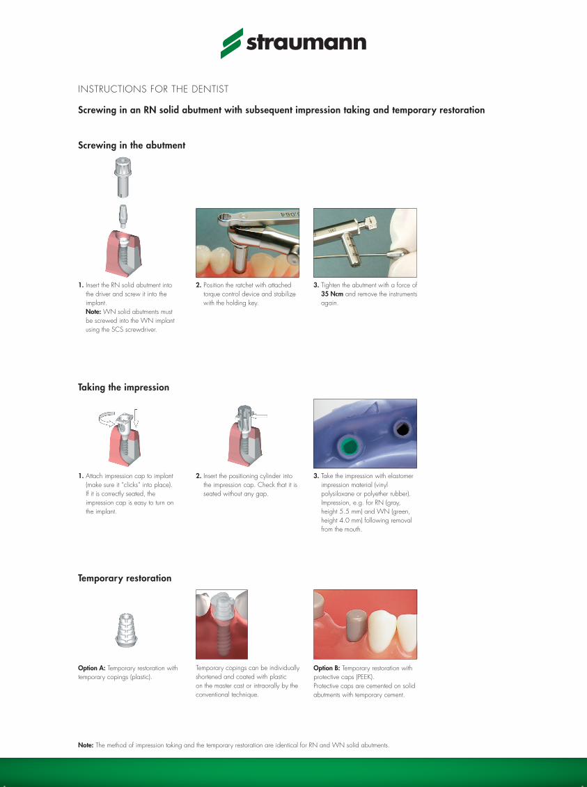
RN and WN synOcta® Angled
Placement of an RN synOcta® Angled abutment into the implant
After fabrication, the restoration is given to the dentist on the master cast together with the abutments.
1. Undo the basal screw with the SCS screwdriver and remove the abutment with index from the master cast.
2. Insert the abutment into the implant and tighten the basal screw to a torque of 35 Ncm.
1. Undo the basal screw with the SCS screwdriver and remove the abutment with index from the master cast.
2. Insert the abutment into the implant and tighten the basal screw to a torque of 35 Ncm.
3. Remove the index, then cement the restoration.
3. Undo the occlusal screw and remove the index. Then cement or screw in the restoration.
Placement of a WN synOcta® Angled abutment into the implant
Note: If the restoration is cemented, the lateral and occlusal opening must be sealed off with gutta-percha.
Note: Before cementing the restoration, the lateral opening must be sealed off with gutta-percha.

RN = Regular NeckWN = Wide Neck
Art. No. Article Dimensions Material
Transfer of the RN and WN synOcta® Angled abutments
048.000V4 Transfer aid for RN synOcta® Angled, short, 15° and 20° height 4 mm plastic
048.002V4 Transfer aid for RN synOcta® Angled, long, 15° and 20° height 4 mm plastic
048.032 Transfer aid for WN synOcta® Angled, 15° height 5 mm plastic
048.350048.350V4
SCS occlusal screw length 4.4 mm titanium
Important: For tightening the basal screw, the ratchet (Art. No. 046.119) with attached torque control device(Art. No. 046.049) and an SCS screwdriver (Art. No. 046.400/401/402) are required.
Important: The abutment must be positioned in the octagon before the screw is tightened. The basal screw in the RN and WN synOcta® Angled abutment is tightened to a torque of 35 Ncm.
Important: If a screw-retained restoration is used, the SCS occlusal screw must be tightened to a torque of 15 Ncm.
Prosthetic instruments
SCS screwdriver (extra short 046.400, short 046.401, long 046.402)
Ratchet, incl. service instrument 046.119
Torque control device for ratchet 046.049
Holding key 046.064
Caution: The plastic parts are intended for single use only. They must not be sterilized. To avoid damage (loss of elasticity, embrittlement) to the plastic parts, they must be protected from exposure to strong light or heat.
For detailed information, refer to our brochure “Crown and Bridge Restorations with the synOcta® Prosthetic System”, Art. No.152.255.
01/08 152.259/e

INSTRUCTIONS FOR THE DENTIST
RN synOcta® Transversal
Placement of an RN synOcta® Transversal (TS) abutment into the implant
After fabrication, the restoration is given to the dentist on the master cast together with the abutments.
1. Undo the basal screw with the SCS screwdriver and remove the index from the master cast.
2. Insert the abutment into the implant and tighten the basal screw to a torque of 35 Ncm. Then incorporate the superstructure.
3. Attach the restoration with the transversal screw, and carefully hand-tighten the transversal screw with the TS hexagonal screwdriver.

RN = Regular Neck
Important: For tightening the basal screw, the ratchet (Art. No. 046.119) with attached torque control device(Art. No. 046.049) and an SCS screwdriver (Art. No. 046.400/401/402) are required.
Important: The abutment must be positioned in the octagon before the screw is tightened. Tighten the basal screw in the RN synOcta® Transversal (TS) abutment to a torque of 35 Ncm.
Important: The transversal screw must only be hand-tightened with the TS screwdriver (Art. No. 046.420).
Prosthetic instruments
SCS screwdriver (extra short 046.400, short 046.401, long 046.402)
Ratchet, incl. service instrument 046.119
Torque control device for ratchet 046.049
Holding key 046.064
TS hexagonal screwdriver 046.420
Caution: The plastic parts are intended for single use only. They must not be sterilized. To avoid damage (loss of elasticity, embrittlement) to the plastic parts, they must be protected from exposure to strong light or heat.
For detailed information, refer to our brochure “Crown and Bridge Restorations with the synOcta® Prosthetic System”, Art. No. 152.255.
Art. No. Article Dimensions Material
Transfer of the RN synOcta® Transversal (TS) abutment
048.003V4 Transfer aid for RN synOcta® TS abutment height 5 mm plastic
01/08 152.259/e
INSTRUCTIONS FOR THE DENTIST
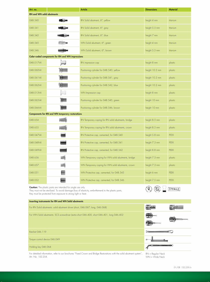
Screwing in an RN solid abutment with subsequent impression taking and temporary restoration
1. Insert the RN solid abutment into the driver and screw it into the implant. Note: WN solid abutments must be screwed into the WN implant using the SCS screwdriver.
2. Position the ratchet with attached torque control device and stabilize with the holding key.
3. Tighten the abutment with a force of 35 Ncm and remove the instruments again.
1. Attach impression cap to implant (make sure it “clicks” into place). If it is correctly seated, the impression cap is easy to turn on the implant.
2. Insert the positioning cylinder into the impression cap. Check that it is seated without any gap.
3. Take the impression with elastomer impression material (vinyl polysiloxane or polyether rubber). Impression, e.g. for RN (gray, height 5.5 mm) and WN (green, height 4.0 mm) following removal from the mouth.
Option B: Temporary restoration with protective caps (PEEK). Protective caps are cemented on solid abutments with temporary cement.
Option A: Temporary restoration with temporary copings (plastic).
Temporary copings can be individually shortened and coated with plastic on the master cast or intraorally by the conventional technique.
Note: The method of impression taking and the temporary restoration are identical for RN and WN solid abutments.
Screwing in the abutment
Taking the impression
Temporary restoration
RN = Regular NeckWN = Wide Neck
Art. no. Article Dimensions Material
RN and WN solid abutments
048.540 RN Solid abutment, 6°, yellow height 4 mm titanium
048.541 RN Solid abutment, 6°, gray height 5.5 mm titanium
048.542 RN Solid abutment, 6°, blue height 7 mm titanium
048.545 WN Solid abutment, 6°, green height 4 mm titanium
048.546 WN Solid abutment, 6°, brown height 5.5 mm titanium
Color-coded components for RN and WN impressions
048.017V4 RN impression cap height 8 mm plastic
048.060V4 Positioning cylinder for 048.540, yellow height 10.2 mm plastic
048.061V4 Positioning cylinder for 048.541, gray height 10.2 mm plastic
048.062V4 Positioning cylinder for 048.542, blue height 10.2 mm plastic
048.013V4 WN Impression cap height 8 mm plastic
048.065V4 Positioning cylinder for 048.545, green height 10 mm plastic
048.066V4 Positioning cylinder for 048.546, brown height 10 mm plastic
Components for RN and WN temporary restorations
048.654 RN Temporary coping for RN solid abutments, bridge height 8.5 mm plastic
048.655 RN Temporary coping for RN solid abutments, crown height 8.5 mm plastic
048.047V4 RN Protective cap, cemented, for 048.540 height 5.8 mm PEEK
048.048V4 RN Protective cap, cemented, for 048.541 height 7.3 mm PEEK
048.049V4 RN Protective cap, cemented, for 048.542 height 8.8 mm PEEK
048.656 WN Temporary coping for WN solid abutments, bridge height 7.3 mm plastic
048.657 WN Temporary coping for WN solid abutments, crown height 7.3 mm plastic
048.051 WN Protective cap, cemented, for 048.545 height 6 mm PEEK
048.052 WN Protective cap, cemented, for 048.546 height 7.5 mm PEEK
Caution: The plastic parts are intended for single use only. They must not be sterilized. To avoid damage (loss of elasticity, embrittlement) to the plastic parts, they must be protected from exposure to strong light or heat.
Inserting instruments for RN and WN Solid abutments
For RN Solid abutments: solid abutment driver (short, 046.067; long, 046.068)
For WN Solid abutments: SCS screwdriver (extra short 046.400, short 046.401, long 046.402
Ratchet 046.119
Torque control device 046.049
Holding key 046.064
For detailed information, refer to our brochures “Fixed Crown and Bridge Restorations with the solid abutment system”, Art. No. 152.254.
01/08 152.259/e

INSTRUCTIONS FOR THE DENTal TECHNICIaN
Fabrication of a mesostructure with the RN synOcta® gold abutment and a cement-retained crown
Fabrication of the mesostructure
1. In order to design the emergence profile optimally on the neck of the crown, a gingival mask should be made on the master cast.
2. attach the RN synOcta® gold abutment to the analog, ensuring that the abutment is aligned in the octagon of the analog. Then hand-tighten the screw with an SCS screwdriver.
3. If required, the modeling aid can be shortened occlusally to suit the anatomical conditions.
5. Check for correct spacing with the silicone index from the wax-up.
6. For reasons of hygiene, the mesostructure/crown cement gap must not be more than 2.0 mm below the gingiva.
7. Embed the mesostructure. Do not use a wetting agent! To prevent the cast-on alloy over-flowing, it is essential to clean the slender edge of the coping and the internal configuration thoroughly with alcohol.
8. Cast the mesostructure in the con-ventional way. Do not use speed investment materials! Follow the instructions for use provided by the manufacturer of the invest-ment material and cast-on alloy!
9. Carefully devest the casting using only ultrasound, water jet or pickling. Do not sandblast!
10. Finish the mesostructure. Polish the subgingival part.
4. Make a wax model of the meso-structure on the abutment. Minimum wax thickness 0.7 mm.

RN = Regular Neck
Art. No. Article Dimensions Material
RN synOcta® gold abutment for transocclusal screw-retained or cement-retained crowns
048.642 RN synOcta® gold abutment for premounted modeling aid (including screw*)
height 14.1 mm Ceramicor/burn-out plastic/titanium
*also available as spare part art. No. 048.356
For detailed information, refer to our brochure “Crown and Bridge Restorations with the synOcta® Prosthetic System”, art. No. 152.255.
Fabrication of the cement-retained crown
11. Block out the screw channel and model the crown.
12. Invest, cast and veneer the crown in the conventional way.
13. a The mesostructure with the finished crown.
13. b
01/08 152.259/e

![Efficacy of gutta-percha solvents used in endodontic ...revodonto.bvsalud.org/pdf/rsbo/v10n4/a09v10n4.pdf · endodontic treatment failure [9]. The clinical diagnosis of the pulp and](https://static.fdocuments.us/doc/165x107/5ed5a14f1b7fdd786a1b5e23/efficacy-of-gutta-percha-solvents-used-in-endodontic-endodontic-treatment-failure.jpg)


![Apexification Using MTA : A Challenging ApproachApexification using MTA was planned. Gutta Percha was removed w.r.t. 11 [Figure 3] and working length was determined(23mm) .[Figure](https://static.fdocuments.us/doc/165x107/5f159340e64c873f23089f2c/apexification-using-mta-a-challenging-apexification-using-mta-was-planned-gutta.jpg)