
Instructions for service - Duerkopp Adler · Conversion or changes to the machine must be...
34
Instructions for service 4260 - 6 Minerva Boskovice, a.s., SokolskÆ 60, CZ - 680 17 Boskovice Tel.: +420-501-453434, 453433, 494111 Fax: +420-501-452165 http://www.minerva-boskovice.com Edition: 05/2002 Printed in Czech Republic 735 342 000 499
Transcript of Instructions for service - Duerkopp Adler · Conversion or changes to the machine must be...

Instructions for service
4260 - 6
Minerva Boskovice, a.s., Sokolská 60, CZ - 680 17 BoskoviceTel.: +420-501-453434, 453433, 494111 Fax: +420-501-452165 http://www.minerva-boskovice.com
Edition: 05/2002 Printed in Czech Republic 735 342 000 499
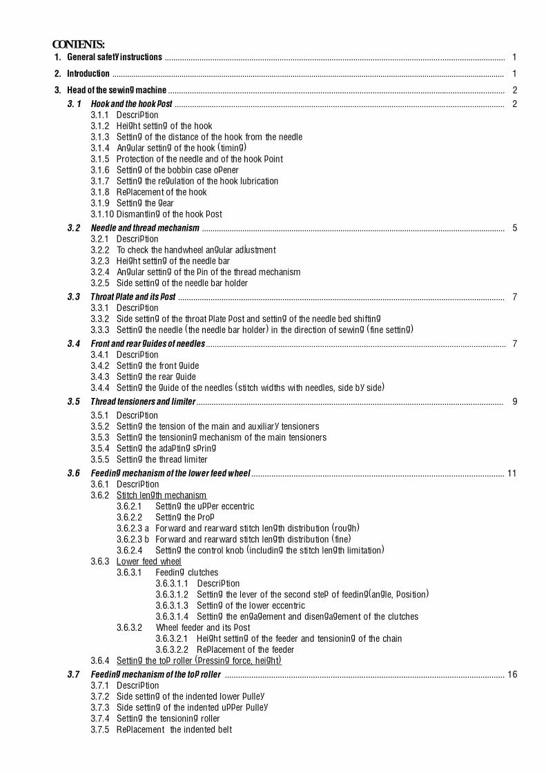
CONTENTS:1. General safety instructions ............................................................................................................................................................. 1
2. Introduction ........................................................................................................................................................................................... 1
3. Head of the sewing machine ........................................................................................................................................................... 2
3. 1 Hook and the hook post ........................................................................................................................................................ 23.1.1 Description3.1.2 Height setting of the hook3.1.3 Setting of the distance of the hook from the needle3.1.4 Angular setting of the hook (timing)3.1.5 Protection of the needle and of the hook point3.1.6 Setting of the bobbin case opener3.1.7 Setting the regulation of the hook lubrication3.1.8 Replacement of the hook3.1.9 Setting the gear3.1.10 Dismantling of the hook post
3.2 Needle and thread mechanism .............................................................................................................................................. 53.2.1 Description3.2.2 To check the handwheel angular adjustment3.2.3 Height setting of the needle bar3.2.4 Angular setting of the pin of the thread mechanism3.2.5 Side setting of the needle bar holder
3.3 Throat plate and its post ...................................................................................................................................................... 73.3.1 Description3.3.2 Side setting of the throat plate post and setting of the needle bed shifting3.3.3 Setting the needle (the needle bar holder) in the direction of sewing (fine setting)
3.4 Front and rear guides of needles ......................................................................................................................................... 73.4.1 Description3.4.2 Setting the front guide3.4.3 Setting the rear guide3.4.4 Setting the guide of the needles (stitch widths with needles, side by side)
3.5 Thread tensioners and limiter ............................................................................................................................................. 9
3.5.1 Description3.5.2 Setting the tension of the main and auxiliary tensioners3.5.3 Setting the tensioning mechanism of the main tensioners3.5.4 Setting the adapting spring3.5.5 Setting the thread limiter
3.6 Feeding mechanism of the lower feed wheel .................................................................................................................. 113.6.1 Description3.6.2 Stitch length mechanism
3.6.2.1 Setting the upper eccentric3.6.2.2 Setting the prop3.6.2.3 a Forward and rearward stitch length distribution (rough)3.6.2.3 b Forward and rearward stitch length distribution (fine)3.6.2.4 Setting the control knob (including the stitch length limitation)
3.6.3 Lower feed wheel3.6.3.1 Feeding clutches
3.6.3.1.1 Description3.6.3.1.2 Setting the lever of the second step of feeding(angle, position)3.6.3.1.3 Setting of the lower eccentric3.6.3.1.4 Setting the engagement and disengagement of the clutches
3.6.3.2 Wheel feeder and its post3.6.3.2.1 Height setting of the feeder and tensioning of the chain3.6.3.2.2 Replacement of the feeder
3.6.4 Setting the top roller (pressing force, height)
3.7 Feeding mechanism of the top roller ............................................................................................................................... 163.7.1 Description3.7.2 Side setting of the indented lower pulley3.7.3 Side setting of the indented upper pulley3.7.4 Setting the tensioning roller3.7.5 Replacement the indented belt

3.7.6 Setting the feeding difference3.7.7 Replacement of friction wheels of the drive conversion unit3.7.8 Top roller
3.7.8.1 Selection of the top roller diameter3.7.8.2 Forward, rearward and side setting3.7.8.3 Setting the gear clearance and in the mounting of the top roller3.7.8.4 Replacement of the top roller
3.8 Setting the top roller lift ..................................................................................................................................................... 20
3.9 Bobbin winder ..................................................................................................................................................................... 213.9.1 Description3.9.2 Setting the bobbin winder stop3.9.3 Setting the friction gear
3.10 Safety clutch ......................................................................................................................................................................... 223.10.1 Description3.10.2 Setting the disengaging moment
3.11 Indented belt transmission ............................................................................................................................................... 223.11.1 Setting the tensioning roller of the indented belt3.11.2 Replacing the indented belt
3.12 V-belt, motor - head ............................................................................................................................................................ 233.12.1 Tensioning3.12.2 Replacing the V-Belt
3.13 Driving toothed belt.............................................................................................................................................................. 233.13.1 To exchange the driving toothed belt
3.14 Lubrication ............................................................................................................................................................................. 243.14.1 Description3.14.2 Refilling oil3.14.3 Multiple oil use
4. Thread trimming ............................................................................................................................................................................... 254.1 Description of the trimming mechanism4.2 Setting the pickup roller4.3 Setting the cam4.4 Setting the fork4.5 Setting the moving knife4.6 Setting the fixed knife4.7 Setting the retaining spring of the hook thread4.8 Setting the switching of the electromagnets
5. Lifting the top roller by electromagnet ...................................................................................................................................... 275.1 Description5.2 Setting the electromagnet pin5.3 Setting the electromagnet current5.4 Assembly of the top roller lifting electromagnet
6. Backtacking using electromagnet ................................................................................................................................................ 286.1 Description6.2 Electromagnet height setting6.3 Setting the position of push-buttons6.4 Change of the function push-buttons
7. Connecting the electric elements on the machine head ....................................................................................................... 29
8. Drive, control panel, position sensor ....................................................................................................................................... 29
9. Lighting ............................................................................................................................................................................................ 299.1 Mounting on the machine head9.2 Lamp replacement
10. Maintenance (table of operations) ............................................................................................................................................. 30
11. Setting the machine according to the sewing category .......................................................................................................... 3011.1 Introduction11.2 Table of setting the machine according to the sewing category11.3 Table of possible stitch widths of needles according to the sewing category

1
1. General safety instructions
The non-observance of the following safety instructions can cause bodily injuries or damages to the machine.
1. The machine must only be commissioned of the instruction book and operated by persons with appropriate training.
2. Before putting into service also read the safety rules and instructions of the motor supplier.
3. The machine must be used only for the purpose intended. Use of the machine without the safety devices is not permitted. Observeall the relevant safety regulations.
4. When gauge parts are exchanged (e.g. needle, top roller, needle plate, feed dog and bobbin) when treading, when theworkplace is left, and during service work, the machine must be disconnected from the mains by switching off the masterswitch or disconnecting the mains plug.
5. Daily servicing work must be carried out only by appropriately trained persons.
6. Repairs, conversion and special maintenance work must only be carried out by technicians or persons with appropriate training.
7. For service or repair work on pneumatic systems the machine must be disconnected from the compressed air supply system.Exceptions to this are only adjustments and functions checks made by appropriately trained technicians.
8. Work on the electrical equipment must be carried out only by electricians or appropriately trained persons.
9. Work on parts and systems under electric current is not permitted, except as specified in regulations DIN VDE 0105.
10. Conversion or changes to the machine must be authorized by us and made only in adherence to all safety regulations.
11. For repairs, only replacement parts approved by us must be used.
12. Commissioning of the sewing head is prohibited until such time as the entire sewing unit is found to comply with EC directives.
It is absolutely necessary to respect the safety instructions marked by these signs.Danger of bodily injuries !Please note also the general safety instructions.
IMPORTANT WARNING
In spite of all safety measures made on the machines, inappropriate actions of the operator may lead to dangerous situations. In industrialsewing machines Minerva, attention should be paid to the following still remaining possible sources of injury:
1. Moving sewing needle- risk of injury when sewing with raised pressure foot or top roller, because the finger guard is then positioned too high.
2. Moving thread take-up lever- risk of injury when inadvertently or intentionally inserting the finger(s) between the thread take-up lever and its guard.
3. Moving pressure member- risk of injury when holding sewn work in immediate vicinity of the pressure member and beginning to insert under the pressure
member a considerably thicker sewn work portion,- risk of injury when sinking the pressure member.
4. When switched off, the clutch motor slows down by inertia but would be reactivated by an accidental treading down of themotor treadle. To avoid such risk, it is advised to hold the handwheel by hand and slightly to depress the motor treadle.
2. Introduction
This service book contains instruction for regulating the mechanisms of the sewing machine head.
The instructions for use and for putting the machine into operation and for the control of the stopmotor are not included in this servicebook, but they are supplied as separate publications.
This service book is universal for all subclasses of the machine - it contains setting procedures for all elements which may be placed onthe machine of the given class. When the supplied subclass of this machine does not include some element, then it is possible to leave outthe respective parts of the instructions. The optional equipments of the machine and the respective configurations of the subclasses ofthe machine are given in the operating instructions.
This sewing machine disposes of a large extent of its use. The machine should be set with respect to the parameters of the sewn material,the sewing thread etc. The setting for the individual categories is given in the chapter 11.2.
For setting the machine, simple setting aids are used which are included in the accessory of the machine. Besides these aids, universalmeasuring devices are used, such as slide calliper, feeler gauges and dynamometer for measuring the thread tension.

2
3. Head of the sewing machine
3.1 Hook and the hook post
3.1.1 DescriptionThe hook (1) is mounted on the shaft (2) and is driven by the gear(3) from the shaft (4).The shaft of the hook (2) is mounted on the top in a sliding bearingand, on the bottom, in a needle bearing.The hook is provided with a lever (6) which is tilted when removingthe bobbin (7). The protecting sheet (8) protects against thecollision of the needle with the hook point. The bobbin case opener(9) is driven by the eccentric (10) on the shaft (2).The lubricating tube (11), on which a lubricating wick is fastenedin the tube (12), feeds oil for lubricating the sliding bearing (5) ofthe eccentric (10) and the hook path.The screws (13) serve for taking up the clearance of the gear. Thescrews (14) fasten the post to the bedplate.The lubricating felt (15) is connected by the wick (16) with themain lubricating system and serves for lubricating the gear (3).
3.1.2 Height setting of the hookThe designated distance �A� should be 6.1 mm.
Caution! Danger of injury!Switch off the main switch ! Before starting the settingoperation, wait until the motor stops!
- Loosen both screws (2).- By turning the screws (3 and 4), set the required distance�A�.
After having set it, tighten carefully the screws.- By axial shifting of the gear wheel (5), set the axial clearance
in such a way that this clearance is the least possible, butsufficient for turning easily the hook.
- Tighten carefully the screws (2). Caution ! One of these screwsmust bear on the flat of the shaft 6).
3.1.3 Setting the distance of the hook fromthe needle
The hook point (1) is set up to the maximum distance of 0.1mm from the bottom of the needle recess (2). For the sewingcategories 1 and 2, the needle size 90 is set, for the sewingcategories 3 and 4, it is the needle size 160.
Caution! Danger of injury!Switch off the main switch ! Before starting the settingoperation, wait until the motor stops!
- Shift the plate (3).- Loosen only one screw (4).- Loosen the screws (5) and tighten them only slightly.- Shift the hook post (6) at the determined distance between the
needle and the hook point.- Tighten carefully the screw (4) (be sure not to damage the
threads!)- Tighten duly the screws (5).- Check up the setting using a narrow strip of thin paper and
proceed to the eventual correction of setting.
Caution!When changing substantially the sewing catego-ry, the protecting sheet of the hook (7) should beset up.
1
2
34
67
89
10
11
12
5
13
14
15
16
6
45
5
3
1
7
max. 0,1
2
4
5
A34
2
6
A

3
3.1.4 Angular setting of the hook (timing)The hook is to be angularly set in such a way that the hookpoint (1) is opposite the needle at the moment, when theneedle shifts by 2.5 mm from its bottom dead center. Thiscorresponds to the 2O5° on the scale of the handwheel (3).
Caution! Danger of injury!Switch off the main switch! Before starting the settingoperation, wait until the motor stops!
- Remove the throat plate.- Turn the handwheel (3) to the 2O5° and fix it with the screw
(4) which is component part ot the accessory of the machine(tighten it carefully).
- Loosen the screws (5).- Turn the hook into the required position.- Set up the distance of about 0,5 mm between the gear wheel
(6) and the pin (7).- Tighten to the maximum the screws (5).
3.1.5 Protection of the needle and of the hook pointThe protecting sheet (1) is to be set up in such a way that theclearance between the protecting sheet and the needle (2) is theleast possible.
Caution ! Danger of injury!Switch off the main switch! Before starting the settingoperation, wait until the motor stops!
- Remove the throat plate and the movable trimming knife.- Unscrew the screw (3).- Put the screwdriver into the hole of the screw (3) and, using the
regulating screw, set up the required clearance between theneedle (2) and the protecting sheet (1). When turning to theright, the protecting sheet shifts out from the groowe andinversely.
- Check up the protecting effect in pushing against the needle inthe sense of the arrow (5). The hook point must not catch theneedle. If so, set up the protecting effect, correct eventually thesetting of the distance of the hook point from the needle accord-ing to the paragraph 3.1.3.
- Screw in the screw (3).
3.1.6 Setting of the bobbin case openerThe bobbin case opener (1) is to be set in such a way that, at themoment when the opener is in its dead centre, there would be aclearance �A� between the opener (1) and the projection (2),whereas the finger (3) bears on the projection (4), �A� = 0.7 mmfor the sewing category 1 and 2, �A� = 0.3 mm for the sewingcategory 3 and 4.
Caution ! Danger of injury!Switch off the main switch! Before starting the settingoperation, wait until the motor stops!
- Remove the sheet guard of the hook post.- On the handwheel (5), set the angle of 295° (the hook is in
its dead centre).- Loosen the screw (6).- Turn the eccentric (7) in such a way that the required clearance
between the elements (1) and (2) is attained.- Set the height of the eccentric (7) in such a way that it is in its
highest position in retaining the minimum clearance betweenthe slide (8) and the fork (9).
- Tighten duly the screw (6).
12
3
4
205o
5 7
6 ~ 0,5
1
2
5
31
1
A
2
3
4
6
5
A
295o
7
8
69

4
3.1.7 Setting the regulation of the hook lubricationBy turning the lubricating tube (1) in the sense of the arrow(2), the size of the contacting surface between the wick (3)and the felt insert (4) is regulated. In this way, the speed of thecapillary lift of oil into the felt insert (5) is influenced, fromwhich oil is wiped on the surface (6) and is driven by centrifugalforce into the hook path (7).Setting of full lubrication- Turn the screw (8) into the position (9).Setting of limited lubrication- Turn the screw (8) into the position (10).After having ended the regulation, set the height of the lubricatingtube (1) at 0.4 mm from the eccentric (11).
3.1.8 Replacement of the hook
Caution! Danger of injury!Switch off the main switch ! Before starting the settingoperation, weit until the motor stops!
- Remove the throat plate and the trimming knife.- Unscrew the screws (1) and remove the gib (2).- After having suitably turned a bit the hook, remove the bobbin
case (3).- Unscrew thorougly the screw (4).- Remove the body of the hook (5) upwards.- When mounting, the procedure is inverse.
3.1.9 Setting the gearThe mutual angular orientation of the gear wheel (1) relativeto the gear wheel (2) should ensure the accessibility of thescrew (5) at the moment when the hook point comes to lieopposite the needle (4). The wheel (2) is to be set with its gearrim symmetrically to the centre of the gear wheel (1). Theclearance between the gear wheels is to be the least possible.
Caution ! Danger of injury!Switch off the main switch! Before starting the settingoperation, wait until the motor stops!
- Set the angle of 2O5° on the handwheel (6) and lock it with thescrew (7).
- On the removed post of the hook (8), according to the pa-ragraph 3.1.10, the hook point (3) is to be turned a bitaccording to the illustration.
- Turn the gear wheel (2) into the suitable position and insert thepost of the hook into the machine according to the respectivearrows. Check up, whether the screw (5) is accessible and,if not, repeat the procedure.
- Set the the distance of the hook from the needle according tothe paragraph 3.1.3.
- Set the precise angular displacement of the hook according tothe paragraph 3.1.4.
- Loosen the screw (10) and tighten them slightly.- Set the clearence in the gear in turning the screws (9). Check
up, whether the gear has a clearance during the whole revolutionof the hook. Turn the handwheel step by step by 15° and, witheach step, grasp the hook and try, if there is an angular deadtravel. Tighten carefully the screws (9).
- Tighten duly the screws (10) and try anew the clearance of thegear.
1
2
3
4
5
4
3
6
205o
7
10
9
8
109
1
5
2
~ 0,5
1
5
2
~ 0,5
12
1
34
56 7
110,
4
8
10
9
15 o

5
3.1.10 Dismantling of the hook postWhen dismantling the post (1), the supplies of lubricating oilare to be disconnected first, the fastening screws unscrewedand, thereafter, the post is removed.
Caution ! Danger of injury!Switch off the main switch! Before starting the settingoperation, wait until the motor stops!
- Unscrew the screw (2).- Push the lubricating tube (3) downwards into the post.- Disconnect the hose with the wick.- Loosen only one screw (5).- Unscrew the screws (6).- Shift the post in the sense of the arrows and remove it out from
the machine.- When mounting it, proceed inversely. Make sure that the
wicks in the tubes are in contact with the other wicks leadingoil into the box (7).
3.2 Needle and thread mechanism
3.2.1 DescriptionThe take-up lever (1) is mounted in ball bearings, both at the spotof its suspending on the connecting rod (2) and in the mountingon the loop (12). The take-up lever is of aluminum and is providedwith a stuck-in eye for two threads. The connecting rod (2) ismounted on the pin (3). The needle bar holder (4) is mountedthrough the pin (5) in a rotating way in the arm (6). In its upperpart, the holder is fastened with the screw (7).The connecting rod (10) of the needle bar (11) on the loop(12) is mounted in a ball bearing and it is slidingly mountedon the needle bar carrier. The mechanism is lubricated by meansof a central-wick lubricating system.
3.2.2 To check the handwheel angular adjustmentThe handwheel (5) must be situated in its precise positionrelative to the needle and thread mechanism. This position isgiven by a pin (2), which locks the connecting rod of theneedle rod (1) through a hole in the arm (3). In this position,the indicator (6) of the handwheel must show �O�. The positionis fixed by the handwheel screw (4) contacting a small flatsurface provided on the upper shaft.The correct adjustment of the angular position has been car-ried out at the producer�s.
Caution ! Danger of injury!Switch off the main switch! Before starting thesetting operation, wait until the motor stops!
1
2
3
45
6
0o
1
5
6
6
3
2
1
7
11
45
10
3
1
27
12
6

6
3.2.3 Height setting of the needle barAt the moment, when the hook point passes around the needle,the upper edge of the needle eye must be about 1 mm belowthe hook point. In an opposite case, it is necessary to set theheight of the needle bar as follows:
Caution ! Danger of injury!Switch off the main switch! Before starting the settingoperation, wait until the motor stops!
- Remove the front guard.- Loosen the screw (1) of the needle bar carrier.- Set the correct height of the needle bar and tighten anew the
screw (1).
Caution !An incorrect setting of the needle bar height maycause the striking of the hook point against the needle.
3.2.4 Angular setting the pin of the threadmechanism
The hinged pin (2) of the connecting rod (3) can be set inthree positions (the pin has got 3 flats ground for the screw):- for the hook of small diameter (value �A� � minimum)- for the hook of large diameter , sewing category 100 and
200 (value �A� = medium)- for the hook of large diameter, sewing category 300 and
400 (value �A� � maximum)The value �A� is to be measured in the bottom position of thetake-up lever. Set the pin of the connecting rod as follows:
Caution! Danger of injury!Switch off the main switch! Before starting thesetting operation, wait until the motor stops!
- Remove the front guard.- Set the lowest (bottom) position of the take-up lever.- Loosen the screw (1) of the pin (2) of the connecting rod (3).- The position of the take-up lever is changed when turning
the pin (2).- Set the pin (2)into the corresponding position and tighten
anew the screw (1).The correct position is given by the flat on the pin (2), onwhich the screw (1) is to be tightened.
3.2.5 Side setting of the needle bar holderThe correct position of this holder is in such case, when the needlebar is lined up with the presser-foot bar. The needle bar holdercan be set as follows:
Caution! Danger of injury!Switch off the main switch! Before starting the settingoperation, wait until the motor stops!
- Loosen the screw (1) of the pin (2).- Loosen the screw (3) of the pin (4).- In shifting the pin (2) set the needle bar holder on the measure
�A� = 7.5 mm (distance of the front faces of the arm and ofthe needle bar holder) /at the same time the pin (4) shifts/.
- The guide pin (4) is to be set in such a way that the needlebar holder moves easily.
- Tighten the screws (1 and 3).
1
2
3
A
1
A
2
34
11

7
3.3 Throat plate and its post
3.3.1 DescriptionThe throat plate (1) is always for the given stitch width ofneedles and universal for all respective categories of sewing(see Tab. sewing equipments - Spare parts list).In the throat plate there is mounted an exchangeable throatplate insert (2). For each stitch width of needles, it is possibleto supply several throat plate inserts differing one fromanother by the width of the piercing hole.
3.3.2 Side setting of the throat plate post andsetting of the needle bed shifting
The throat plate post (1) and the needle holder (2) are to bemutually positioned in such a way, so that, with the givenstitch width �A�, both needles pass through the centres of theneedle penetration holes.
Caution! Danger of injury!Switch off the main switch! Before starting thesetting operation, wait until the motor stops!
- Loosen the screw (3) of the needle bar carrier.- Shift the needle bed (2) in such a way, so that the required
stitch width of needles �A" is attained.- Tighten up the screw (3) and check up the setting.- Loosen the screws (4) /from the rear side of the post too/.- Shift the post (1) in the right direction in such a way, so that
both needles pass through the centres of the needle pene-tration holes.
- Tighten up the screws (4) and check up the correctness ofsetting.
3.3.3 Setting the needle (the needle bar holder) inthe direction of sewing (fine setting)
Caution! Danger of injury!Switch off the main switch! Before starting thesetting operation, wait until the motor stops!
- Loosen the screw (5).- In turning the needle bar holder (7), set the needle against
the centres of the needle penetration holes.- Tighten up the screw (5) and check up the setting.
Caution!A faulty setting may cause bending or breaking ofneedles against the throat plate insert.
3.4 Front and rear guides of needles3.4.1 DescriptionThe front guide (1) and the rear guide (2) are used togetherfor stitch widths of a tandem arrangement. For stitch widthswith needles side by side, the rear guide (3) is used only. Allguides serve for holding the sewn material against the throatplate. In addition to this, they contribute to a as well andprotect the needles in guiding them into the piercing holes.
1
2
1
2
4
3
6
5
A
12
3

8
3.4.2 Setting the front guideThe front guide is universal for tandem stitch widths and forall categories of sewing. It should be set in such a way that,from the point of view of the operator, it protects the rightneedle from the left-hand side. In the that, when backwardstitching, it could not negatively influence the stitch locking.Its correct height is set up according to the sewn material1-2 mm above the bottom edge of the feeding wheel. Forharder materials, it is set a bit lower and inversely.
Caution! Danger of injury!Switch off the main switch! Before starting thesetting operation, wait until the motor stops!
- Loosen the screw (4) and set the correct height of the guide(1). Tighten then the screw.
- Loosen the screw (5) and set the guide (1) in the directionof sewing in front of the left needle at the moment, whenthe needle starts piercing the material and set, at the sametime, the side clearance between the guide and the right-hand needle, tighten then the screw.
- Check up the influence of the setting on the stitch locking.
3.4.3 Setting the rear guideFor different stitch widths of needles there is always used, forall sewing categories, the respective guide (in each sewingset there is supplied a corresponding guide). The rear guideprotects the left needle from the right-hand side. It is to be setin such a way in the direction of sewing that it favourablyinfluences the stitch locking even when sewing the radii. Itscorrect height is set 1-2 mm above the bottom edge of thefeeding wheel, namely according to the hardness of the sewnmaterial.
Caution! Danger of injury!Switch off the main switch! Before starting thesetting operation, wait until the motor stops!
- Loosen the screw (6) and set the guide (2) in the directionof sewing behind the right needle at the moment when theneedle leaves the sewn material, tighten up the screw.
- Loosen the screws (7) and set the guide in its correct heightand, at the same time, set the side clearance between theguide and the left needle, tighten up the screw.
- Check up the influence of setting on the stitch locking.
3.4.4 Setting the guide of the needles (stitchwidths with needles, side by side)
The side setting of the guide is to be done starting from theaxis of the stitch width of the needles, that is to say that theclearances between both needles and the guide must be thesame. The correct height of the guide is set up according tothe sewn material, 1-2 mm above the bottom edge of thefeeding wheel. In the sense of sewing, the guide is to be set insuch a way that the contact of the guide with the material is atthe same spot as the contact of the feeding wheel with thematerial.
Caution! Danger of injury!Switch off the main switch! Before starting thesetting operation, wait until the motor stops!
- Loosen the screws (7) and set the guide (3) into the axis ofthe stitch width of the needles and set the guide in itscorrect height, tighten the screws.
- Loosen the screw (6) and set the guide in the direction ofsewing according to the feeding wheel, tighten the screw.
- Check up the influence of setting on the stitch locking.
7
6
3
1
4
5
6
2
7

9
3.5 Thread tensioners and limiter
3.5.1 DescriptionThe main tensioner (1) serves for creating the tension of thethreads when tightening the stitch. The auxiliary tensioner (2)reduces the risk of pulling out of the thread after the threadtrimming when removing the sewn material, when the threadis passed through this material and when the main tensioneris relieved. The main tensioner is relieved by the mechanismcontrolled by the shaft of the presser foot lifting (3), on whichthe lever (4), is mounted which shifts the prop (5), whichpushes the metal sheet lever (6). This lever shifts the pin (7)and this pin pushes onto the washer (8) and relieves the spring(9).With the machines provided with a thread trimming device,the main tensioner (1) is relieved as well when switching onthe electromagnet (10), when its armature (11) pushes againstthe lever (6). The mechanism of the adapting spring (12)maintains the thread in its tensioned state when passingthrough the hook. The thread limiter (13) limits the length ofthe thread fed by the take-up lever when moving from theupper to the bottom dead centre to get a controlled passingof the thread through the hook.
3.5.2 Setting the tension of the main and auxiliarytensioners
The tension of the main thread tensioner is regulated by meansof the nut (1). The force of tensioning the thread is measuredby the dynamometer (2) as it is shown on the illustration. Thesize of this force differs according to the category of sewingand is indicated in the par. 11.2.The tension of the auxiliary tensioner is regulated using thenut (3). It should be the least possible, but sufficient forunthreading the thread from the sewn material when removingthe sewn material from the pressing element without leavingthe tensioner.
3.5.3 Setting the tensioning mechanism ofthe main tensioners
The nut (1) must be screwed off in such a way that the metalsheet lever (2) bears on the plate (3) and, at the same time, thelever (4) is not limited by the prop (5) in its rotation. The lever(4) must be fixed against the shaft (6) in such a way that,when the presser foot is in its lowest position, the nut (1)bears on the metal sheet lever (2) with its minimum clearance.
Caution ! Danger of injury!Switch off the main switch! Before starting the settingoperation, wait until the motor stops!
- Unscrew thoroughly the nuts (7) and loosen the screw (8).- Put in one line the axis of the shaft (6), the axis (9) and the axis
of the spherical surface of the nut (1).- Unscrew the nut (1), until the metal sheet lever (2) strikes
against the plate (3). However, the lever (4) must rotate freelyin the sense of the arrows in both senses.
- Screw in the nuts (7) almost to the stop.- Remove the sewn material and lower the presser foot.- Turn the lever (4) in the sense of the arrow up to the stop.- Return the lever (4) a bit back and tighten the screw (8).
68
3
1
7
2
5
94
6
8
2
4
1
7
P
3
1
2
P
3 2 1
4 5
7
6 11 8 9
2
113
12
10

10
3.5.4 Setting the adapting springThe mechanism of the adapting springs is to be set up in sucha way that, when unscrewing the nut (1) up to the stop againstthe washer (2), the conical springs (3) remain under the tensionwhich is to be set up by shifting the adjusting ring (4) lockedby the screw (1O).The angular setting thereof is to be done in such a way thatthe angle �A� = 45°. The axial setting is to be done in such away that the plate (5) and the plate (6) are at the mutual distanceequal to the measure �C�= 3 mm.The washers (7) are to be oriented in such a way, so that thedistance �B� = 1 to 1.5 mm. The bushings (8) are to be orientedin such a way that the adapting springs (9) are tensed up by90° from their free state.
Caution! Danger of injury!Switch off the main switch! Before starting the settingoperation, wait until the motor stops!
- Unscrew the nut (1) up to the stop towards the washer (2).- Loosen the screw (10), push heavily the ring (4) against the
washer (2) and tighten the screw (10).- Mount the mechanism of the adapting spring into the machine
in such a way, so that the pieces (5 and 6) are at the distance�C� = 3 mm, set the angle �A� = 45° and tighten the screw(11).
- Turn the washers with their noses (7) in such a way that thedistance �B� = 3 mm is attained.
- Put the screwdriver into the slit in the bushing (8) and turn it incounterclockwise direction, until the spring (9) touches slightlythe nose of the washer (7). Turn then still the bushing (8) by1/4 revolution.
- Tighten the nut (1). In this way, the whole mechanism im-mobilizes.
3.5.5 Setting the thread limiterThe thread limiter is to be set in such a way that, when sewing andpassing the thread through the most distant point of the hook,the spring (2) shifts by about 1/4 to 3/4 length of its total length.This means that the thicker will be the sewn material and the longerwill be the stitch length, the more will be the limiter shifted in thesense of the arrow and inversely. Under standard sewingconditions, the thread limiter is set in its tested positions dependingon the sewing category in accordance with the chapter 11.
Caution! Danger of injury!Switch off the main switch! Before starting thesetting operation, wait until the motor stops!
- Tighten the screw (3).- Set the thread limiter (1) in such a way that the screw (3)
is situated above some letter according to the chapter 11.- Tighten the screw (3).
3
1
2
1
5
6
11
C
9
F
BA
10 8 7 1
4 2
7
33

11
3.6 Feeding mechanism of the lower feed wheel
3.6.1 DescriptionThe feeding mechanism is formed by the leverage (1) whichis driven from the main shaft through the eccentric with connectionrod (2). The feeding movement is transmitted by the shaft (3)by means of the draw bar (5) onto the clutch of the bottomwheel feed (7).The engaging and the disengaging function of the clutch (7)is controlled from the lower shaft (8) through the eccentric withthe connecting rod (9) and through the wedge coupling (10).The feeding movement is transmitted by the shaft (11) throughthe chain transmission (12) onto the wheel feeder (13).The stitch length is set by the knob (14) through the leverage (15)to the feeding mechanism (1).
3.6.2 Stitch length mechanism
3.6.2.1 Setting the upper eccentricThe eccentric (1) is to be set at the respective angle in such away, so that the movement of the needle bar and the feedingby the wheel feeder are correctly phase shifted one againstthe other. This refers to the angle of 90° on the handwheel (2),when the setting stick (3) is engaged into the eccentric (1)and leans from above against the feeding shaft (4).
Caution! Danger of injury!Switch off the main switch! Before starting the settingoperation, wait until the motor stops!
- Set the angle 90° on the handwheel (2) and lock it with thescrew (5) which is included in the accessory of the machine(tighten it carefully).
- Insert the setting stick (3) into the hole in the eccentric (1)and prop it against the feeding shaft (4).
- Shift axially the eccentric on the shaft up to its extremeposition to the right or to the left and place it in the mediumposition.
- Tighten the screws of the eccentric (6) to the utmost (onescrew first and, in turning a bit the handwheel, another screwtoo).
3.6.2.2 Setting the propIn this machine with a wheel feed, the prop (1) is mounted in thepits (A and C) as per the drawing.
3.6.2.3a Forward and rearward stitch lengthdistribution (rough)
The cam (1) is to be set at the respective angle in such a way thatthe stirrup (6) is oriented in such a position, so that the connectingrods (7 and 8) are in a line with a thoroughly screwed in knob (9)and with turning the handwheel at 0°. This setting can be doneonly after having set the top eccentric according to the pa-ragraph 3.6.2.1.
Caution! Danger of injury!Switch off the main switch! Before starting the settingoperation, wait until the motor stops!
- Set the zero stitch /screw in the knob (9) to the bottom ofthe cam (1)/.
- Set the angle 0° on the handwheel and lock it with the screw(4).
- Turn the screw (3) in the respective sense in such a way thatthe connecting rods (7 and 8) are in a line and tighten thescrew (2).
1
3
4
5
2
90o
6
3
2
19
4
0o
6 7 8
CD
AB
1
15
3
5
13
12
14
11 10
8
7
2
1
9

12
3.6.2.3b Forward and rearward stitch lengthdistribution (fine)
When setting the maximum length of the stitch, the forward andthe rearward stitch length must be equal with the maximum errorof ± 5 %. This setting can be done only after having set thewheel feed (par. 3.6.4.1.2).
Caution! Danger of injury!switch off the main switch! Before starting the settingoperation, wait until the motor stops!
- Set the maximum stitch length .- Place a suitable material under the presser foot and mark therein
the forward and the rearward stitch length.- With an unequal length of the stitch, proceed to the correction
of setting by turning the screws (2 and 3). When tightening thescrew (3), the forward length of the stitch is shortened andinversely. When tightening the screw (2), the forward stitchlength is lenghtened. Tighten the screw (2).
3.6.2.4 Setting the control knob (including thestitch length limitation)
The control knob (1) is to be set up in such a way that, whenturning in the counterclockwise sense up to the stop, themaximum stitch length valid for the given sewing categoryand the stitch width is attained. The scale on the control knobis to be oriented in such a position that the respective maxi-mum stitch length on the scale is against the marking on themachine arm.
Caution! Danger of injury!Switch off the main switch! Before starting the settingoperation, wait until the motor stops!
- Screw in the screw of the control knob in such a way thatthe spherical surface of the screw (3) bears on the seat ofthe cam (4).
- Loosen the screw (5) and turn the control knob in the clockwisedirection, until the pin (6) of the knob (1) bears on the pin(7). Tighten firmly the screw (5).
- The control knob (1) is to be set to the maximum stitchlength corresponding to the respective sewing category andto the given stitch width. Check up the set up length by asewing test.
- Loosen the screw (5) and turn the control knob in thecounterclockwise sense, until the pin (6) of the knob (1)bears on the pin (7). Tighten firmly the screw (5). Check itup by a sewing test.
- Put a screwdriver into the hole (8) of the scale (2) and adjustthe scale in such a way that the respective maximum stitchlength on the scale is against the marking on the machinearm.
125
34
6 7
5
12 8
3
2

13
3.6.3 Lower feed wheel3.6.3.1 Feeding clutches3.6.3.1.1 DescriptionThe feeding clutch with machines without the needle feedingis identical with the clutch for the needle feeding. Thedifference is in its function.Feeding is namely realized here byone step. For this reason, the clutch lid (1) is firmly anchoredby the draw bar (2) and by the pin (15) in the machine arm.The rotating motion of the shaft (6) is produced from theoscillating motion of the draw bar (3) through the lever (14),the star (4) and the driving disk (5) firmly connected with theshaft (6).The clutch is coupled by means of the wedge (7) onthe connecting rod (8) through the eccentric (9) which is placedon the lower shaft (10).In the position, when the wedge is disengaged, the star (4)is shifted out from the frictioning engagement with the lining ofthe carrier plate (5) by means of the spring washer (11). The plate(5) lining is then pushed by means of a flat profiled spring (2)against the cover of the clutch (1).In this phase, the shaft (6) is connected with the cover of theclutch (1) which is connected with the machine arm, so thatthe shaft (6) does not rotate and, consequently does not feedthe sewn work.In the position, when the wedge is disengaged, the star (4)is pushed against the plate (5) lining and, at the same time,the friction connection with the cover of the clutch (1) isdisconnected. In this phase, the shaft (6) is connected withthe star (4) and is rotating, which means that it is feeding.Within a short instant, when engaging and disengaging withthe carrier plate (5), there are in a friction engagement boththe cover (1) and also the star (4), namely in the dead centre ofthe connecting rod (3). The setting of the change-over ofclutches is done by tightening or by loosening the nut (13).
3.6.3.1.2 Setting the lever of the feeding(angle, position)
The feeding lever (1) must be set in such a way, so that, whenthe needle is in its lower dead centre, the axis of a part of thestar (2) coincides with the axis of the screw (3).
Caution! Danger of injury!Switch off the main switch! Before starting thesetting operation, wait until the motor stops!
Lever (1) displacement- Loosen the screw (6).- Set the maximum stitch length.- Set the angle 180° on the handwheel.- Unscrew the screw (5) and put the needle shank in its hole.- Turn the lever (1) until the needle drops into the clutch disk (2).- Side set the lever (1) to the measure �A�= 0.5 to 1 mm.- Tighten the screw (6).- Screw in the screw (5) and seal it with the Loctite cement.
7 8 1 4
25A
3
9
1
13
7
4 12
511
6
10
82
14
15
3
23
5
8
6
1

14
3.6.3.1.3 Setting of the lower eccentricThe rotation of the eccentric (3) must be delayed in phase by1/4 revolution against the rotation of the eccentric of the stitchlength. This corresponds to the angle of 244° on the handwheel(1), when the setting pin (4) is put into the eccentric (3) whichis in contact with the indented belt (5).
Caution! Danger of injury!Switch off the main switch! Before starting thesetting operation, wait until the motor stops!
- Set 244° on the handwheel (1) and lock it with the screw(2), which is included in the accessory of the machine(tighten it carefully).
- Put the setting stick (4) into the hole in the eccentric (3) andprop it from below against the indented belt (5).
- Set eccentric (3) axially.- Tighten it the utmost the screws of the eccentric (6).- By means of the handwheel, turn the eccentric (3) into the marked
position and check in this position the clearance �A� = 0.05,proceed eventually to its correction by a new side setting ofthe eccentric.
3.6.3.1.4 Setting the engagement anddisengagement of the clutches
The nut (7) is to be side set in such a way that the shifting ofthe clutches is done at the moment when the clutch disks (3)do not move, which means, when they are at the dead centerof their oscillating movement. This corresponds to the angle90° on the handwheel.
Caution! Danger of injury!Switch off the main switch! Before starting the settingoperation, wait until the motor stops!
- Loosen the screws of the indented pulley of feeding and shift itto the left.
- Set the maximum stitch length.- Set the angle 90° on the handwheel and lock it with the
screw (2). which is included in the accessory of the machine(tighten it carefully).
- Loosen three screws (6) in the nut (7) and unscrew it by2 mm to the left.
- Tighten slowly the nut (7), until it strikes against the axialbearing (9). (At this moment, the tightening momentincreases in jumps) and tighten the screws (6).
- Set the hand wheel on 85° and depress the backtackinglever, the feeder should turn against the sewing direction.Set then the hand wheel on 95°, the feeder should not rotate.If not being so, correct the side setting of the nut (7). Whenthe clutches shift too soon, turn a bit the nut (7) to the rightand inversely.
- Tighten the screws (6).- Return the indented pulley in its original place according to the
paragraph 3.7.2.
1
2
90o
67
9 3
3
6
45
A
244o
2
1

15
3.6.3.2 Wheel feeder and its post
3.6.3.2.1 Height setting of the feeder and tension-ing of the chain
The wheel feeder (1) is to be set in such a way that the pointsof its teeth overtop the throat plate by �X�= 0.3 to 0.7 mm.When sewing soft and thick materials, it is necessary toincrease the value �X�, until a good quality of feeding isattained, but only to the measure of not deteriorating thebeginning of sewing after the carried out thread trimming.With every correction of the teeth height, the tension of thechain (2) is to be corrected.
Caution! Dangere of injury!Switch off the main switch! Before starting the settingoperation, wait until the motor stops!
- Loosen the screw (3).- Loosen the screw (4).- Loosen or tighten the screw (5) and push simultaneously with
finger the feeder (1) downwards, until the required height ofthe teeth �X� of the wheel feeder is attained.
- Tighten then still the screw (5) by 45° (1/8 revolution).- Tension the tensioner (6) up to the stop. Be careful in side
shifting it to the centre of the chain. Tighten the screw (3).- Loosen the screw (5) by 45° (1/8 revolution), into its original
position. In this way, the optimal clearance of the chaintransmission is attained.
- Tighten the screw (4).- Correct the set height of the top roller according to the
par. 3.6.5.
3.6.3.2.2 Replacement of the feederFor the replacement of the wheel feeder (change of the wheelfeeder according to the machine setting - see par. 11.2 - settingof the machine - feeder - pitch of the teeth).
Caution! Danger of injury!Switch off the main switch! Before starting the settingoperation, wait until the motor stops!
- Unscrew the screws (1) and remove the throat plate (2).- Dismantle the hook of the left-hand post (see 3.1.8).- In pulling upwards (securing by a spring), pull out the feeder
(3) with the guide (4).- Replace the feeder (3).- Insert the feeder with the guide into the groove of the holder
(5).- Mount the hook of the left-hand post (see 3.1.8).- Mount the throat plate (2) and tighten up the screws (1).- Check up, if the spring (6) pushes the guide (4) with the
feeder (3) against the wheel (8).- In the opposite case, loosen the screws (9),tense up the
spring in such a way,so that the guide (4) with the feeder (3)is pushed against the wheel (8) and tighten the screws (9).
3
6
2
X
4
5
1
1
6
9
34
582 1

16
4
3
5
1
26
3.6.4 Setting the top roller (pressing force, height)When lowering the top roller (1), set the clearance �A� betweenthe feeder (5) and the top roller to the maximum of 0.2 mm.Set the pressing force of the top roller (1) so as to avoid theslippage of the sewn material when feeding it.Method of setting the height of the top roller:- Lower by hand the presser bar (3) with the top roller (1)
above the wheel feeder (5).- Loosen the screw (4) and set the required value �A� (0.2 mm).- Tighten the screw (4).Setting the force of the top roller (1).- In screwing in the screw (2),the force of the top roller is
increased and inversely.
3.7 Feeding mechanism of the top roller3.7.1 DescriptionThe starting movement for the drive of the top roller feeder is thebottom feeding shaft. From this shaft, the movement is transmittedby the indented belt (1) onto the top feeding shaft (2). A componentpart of the transmission by indented belt is the pulley (3), thetensioning roller (4), the roller (5) and the pulley (6). Startingfrom the shaft (2), the movement is further transmitted throughthe friction wheels (7 and 8) of drive conversion unit onto thearticulated shaft (9). From this articulated shaft, the movementis transmitted by a cone transmission, situated in the holder(10), onto the feeder wheel (11). The drive conversion unitserves for compensating the differences in feeding by thedriven top roller and by the lower feed wheeler. By turning thescrew (12), the change of the gear speed ratio is attained.After having set in accordance with the par. 3.6.6, the screw(12) in the holder (13) is to be locked by the nut (14). Thepressure of the friction wheels (7 and 8) is ensured by thecompression spring in the shaft (2). To avoid a completepushing out from the arm, the shaft is locked by a stirrup ring(17). The shaft of the friction wheel (8) is mounted in thescrew (12) on needle bearings. The articulated shaft (9)contains two joints (15) and a telescopic part (16). Both theseelements secure the lifting and the tilting of the top roller.
3.7.2 Side setting of the indented lower pulleyThe pulley must be set up in such a way that the belt passesthrough the centre of the passing hole in the bedplate. Thesetting operation is to be done as follows:
Caution! Danger of injury!Switch off the main switch! Before starting the settingoperation, wait until the motor stops!
- Loosen the screws (1) of the pulley (2).- Loosen the screw (3) of the tensioning roller (4)- Set the pulley (2) in such a way that the belt (5) passes through
the centre of the passing hole in the bedplate (6).- Tighten the screws (1).- Set the tensioning roller (4) axially in such a way that the belt
(5) is set at the middle of the tensioning roller (4).- Set the tensioning roller (see par. 3.7.4).- Tighten up the screw (3) of the tensioning roller (4).
2
4
3
1
5 A
62
5
1
4
3
159
16
15
1011
178131214
7

17
3.7.3 Side setting of the indented upper pulleyThe pulley is to be set in such a way that the indented belt isnot crossed and the pulleys are in line. The setting thereof isto be done as follows:
Caution! Danger of injury!Switch off the main switch! Before starting thesetting operation, wait until the motor stops!
- Loosen the screws (1) of the pulley (2).- Set the pulley (2) in such a way that the distance of 5 mm
is attained in accordance with the illustration.- Tighten the screws (1).
3.7.4 Setting the tensioning rollerThe tensioning roller of the indented belt of the top feedingis mounted in a rotary way on the bedplate. The belt must be ten-sioned as needed in such a way that there is ensured the correctfunction of the transmission. Insufficient tension can causeskipping of the teeth, on the contrary, excessive tensioningenormously loads the mounting of the top shaft. The setting thereofis to be done as follows:
Caution! Danger of injury!Switch off the main switch! Before starting thesetting operation, wait until the motor stops!
- Loosen the screw (1) securing the lever of the tensioning roller(2).
- Tension the belt as needed (theoretically, in applying the forceof 10 N in the middle of the belt with the deflection of 4 mm).
- Tighten the screw (1).
2
1
1
2
5

18
3.7.5 Replacement the indented beltBefore replacing the indented belt, the bottom feeding shaftis to be removed. The procedure is as follows:
Caution! Danger of injury!Switch off the main switch! Before starting thesetting operation, wait until the motor stops!
- Loosen the screw (1) of the tensioning roller (2) and loosen it.- Loosen the screws (3) of the pulley (4) and shift it to the left in
such a way that the screws (5 and 6) of the feeding clutch (7)are accessible.
- Loosen the screws (5 and 6).- Loosen the screw (8) of the axial ring (9).- Loosen the screws (10) of the chain wheel (11).- Push the shaft (12) to the left in such a way that it is out of the
pulley (4).- Remove the pulley (4).- Remove the front guard.- Loosen and unscrew the screw (4) of the holder of the wheel
(15) and remove it from the holder (24).- Loosen the screws (16 and 17) of the holder (18).- Remove the holder (18) together with the holder (15) and
articulated shaft (13) from the machine.- Loosen the screws (19) of the pulley (20).- Remove the retaining ring (21) from the shaft (22).- Hold the pulley (20) and pull out the feeding shaft (22) from
the arm in such a way that it is possible to remove theindented belt (23) from the arm of the machine.
- Replace the belt with a new one and proceed to the assembly(inverted procedure of dismantling).
- Proceed to the setting operation according to the par. 3.7.2,3.7.3 and 3.7.4.
3.7.6 Setting the feeding differenceThe size of feeding by the driven top roller is regulated by meansof a regulating screw. The top roller feeding is to be set in cases,when a difference between the size of the top and bottom feedingof the sewn material is evident. This will show up in upward ordownward bending of the sewn parts. It is therefore necessary,when bending the sewn parts:1. upwards - to increase the feeding performance of the top roller.2. downwards - to reduce the feeding performance of the toproller.This setting operation is done as follows:- Loosen the locking nut (1) of the adjusting screw (2).- Turn the screw to the left (in increasing so the feeding perfor-
mance of the top roller) or to the right (in reducing so the feedingperformance of the top roller).
- Test the result of this setting in sewing.- Tighten the locking nut (1).- The standard setting for the zero difference is 3 mm (see
Fig.) - the gap between the front faces of the screw (2) andthe nut (1).
1110 12 438912
5 6 7
2415
14
2122
23
20
19
13
17
18
16
2
1
3

19
3.7.7 Replacement of friction wheels of the driveconversion unit
The worn friction wheels (1 and 2) of the drive conversion unit areto be replaced. This is done as follows:
Caution! Danger of injury!Switch off the main switch! Before starting the settingoperation, wait until the motor stops!
- Remove the front guard.- Loosen and unscrew the screw (3) from the holder of the wheel
(4) and remove it from the holder (5).- Loosen the screws (6 and 7) of the holder (8) and remove the
holder (8) with the telescopic shaft (9) and the driven wheelfrom the machine.
- In pulling it out, remove the telescopic shaft (9) from the holder(8).
- Loosen and unscrew the screw (10) and remove the shaft(11) with the friction wheel (12) from the telescopic shaft.
- Press out the pin (13) from the shaft (11) and the wheel(12).
- Replace the wheel (12) by a new one and proceed to a reassembly(an inverse procedure to the dismantling).
- Loosen the screw (14) of the conic friction wheel (15).- Remove the wheel (15) and replace it.- Proceed to a reassembly (an inverse procedure to dismantling).
3.7.8 Top roller3.7.8.1 Selection of the top roller diameterThe machine can be supplied with two types of top roller,namely with the diameter of 25 mm and with the diameter of35 mm. The suitability of the diameter used depends on thetype of sewing and on the concrete technological operation.There are in general valid the following principles for theselection of the wheel diameter:ø 25 mm - for sewing small radiiø 35 mm - for sewing straight sections or big radii
- for sewing with great passages to thicker materials
3.7.8.2 Forward, rearward and side settingThe top roller must be in a defined position in relation to theneedle:a)view (see Fig. 1) - the value �X� depends on the diameter of
use top roller (ø 25 - 6.5 mm; ø 35 - 10.5 mm), it is measuredfrom the the needle bar up to the roller edge when turningthe handwheel to the 180° of the scale against the indicator
b)view (see Fig. 2) - the wheel edge must fit with the edge ofthe left needle operture at the spot of the left needle punch.
These values are to be set as follows:
Caution! Danger of injury!Switch off the main switch! Before starting the settingoperation, wait until the motor stops!
- Loosen the screw (1).- By shifting the holder (2) with the top roller (3) in the groove of
the holder (4) set the required value �X� and tighten the screw(1).- Loosen the screw (5)- By shifting the holder (2) in the holder (6) set the bottom edge
of the roller to the edge of the needle operture.- Tighten the screw (5).
9
7
10
8
6
35
11
1415
13
12
4
X
3
2
6
5
1
4
obr. 2obr. 1

20
3.7.8.3 Setting the gear clearanceand in the mounting of the top roller
In the cone gear of the drive of the top roller, the minimumclearance must be set. A too small clearance will increase thefriction resistance of the gear, the excessive clearance willinfluence the inaccuracy of feeding. The top roller itself ismounted on balls. With this type of mounting,it is alsonecessary to set the minimal possible radial clearance.The given clearances are set as follows:
Caution! Danger of injury!Switch off the main switch! Before starting the settingoperation, wait until the motor stops!
Clearance in the wheel mounting- Loosen three screws (5) /only slightly/.- Using the screw (4) set the minimum clearance in the top
roller mounting (2) /it must easily rotate without any rubbingand with a minimum clearance/.
- Tighten the screws (5), check the set up clearance, even-tually, repeat the setting procedure.
Clearance in the conic gear- Loosen the screw (1), in shifting the wheel, resp. the holder
(3) in the holder groove (6), set the minimum clearance,the pinion (7) must be pushed up to the holder bottom (6).
- Tighten the screw (1), check the set up clearance.
3.7.8.4 Replacement of the top rollerWhen replacing the top roller, proceed as follows:
Caution! Danger of injury!Switch off the main switch! Before starting the settingoperation, wait until the motor stops!
- Unscrew the screw (1).- Unscrew the screw (3) with the washer (2).- Remove the driven top roller with the holder (4) from the holder
(5) and from the articulated shaft (8).- Mount another top roller in inverted procedure to dismantling.- Set the top roller according to the par. 3.7.8.2.
3.8 Setting the top roller liftThe maximum lift of the top roller when lifting the foot withknee lever or with electromagnet is to be �A� = 12.5mm.
Caution! Danger of injury!Switch off the main switch! Before starting thesetting operation, wait until the motor stops!
- Place a cube (1) having the height of �A� = 12.5 ± 0.7 mmunder the top roller.
- Screw in thoroughly downwards the screw (2).- Tighten slightly the screw (3) in such a way that the lever (4)
turns on the shaft (5) with a certain friction moment.- Push with the screwdriver on the lever (4), until it attains
the wall inside the arm of the sewing machine. In thisposition, tighten duly the screw (3).
- Check the axial clearance of the shaft (5) which should bethe least possible.
- Set the normal pressure force of the top roller.
4
5 3 2
1 A
6
3
1
42
5
4
3
1
2
7
5
6

21
3.9 Bobbin winder
3.9.1 DescriptionThe winder (bobbin winder) winds a reserve of the hook thread.It is driven by a spring-mounted friction gear, which stopsafter having filled the bobbin.An ideal winding is attained with a sufficient pretension of thethread obtained on the thread guide (4) and with 1 mm under thediameter of the bobbin. The shaft is mounted in a swinging wayand the friction gear is put into engagement by means of a pickuplever (1) and a cam. The winder is fixed on the machine arm bytwo screws (3). The thread is passed through according to theillustration, the thread is cut off after having stopped the windingoperation using the cutting device (5).
3.9.2 Setting the bobbin winder stopThe moment of interrupting the winding is determined by themutual position of the pickup lever (1) and the cam (5) on acommon shaft.The cam is locked in its functional position by the screw (6). Themutual position is to be set on a not incorporated winder in sucha way that in the moment, when the pickup lever leaves the spaceof the bobbin, the pressing function of the cam on the windersshaft is interrupted and it moves in the sense of the arrow. A finesetting is to be done on an incorporated condition in the machine.Using the screw (2), the position of the friction part of the pickuplever (1) is adapted. In opening the lever, the stopping function isaccelerated. Its inverse function delays it. A test is to be done afterhaving inserted the bobbin, when passing the thread through thedevice and when winding at the running of the machine.
3.9.3 Setting the friction gearThe friction gear is formed frontally by the disk (8) on themain top shaft of the machine and by the disk (7) with a rubberring on the shaft of the winder.
Caution! Danger of injury!Switch off the main switch! Before starting the settingoperation, wait until the motor stops!
- Proceed to the setting operation with a removed rear guard.- The winder is in its stopped position.- Loosen two screws (9) in the disk (8) through the hole in the
arm.- By shifting axially the disk in the sense A, B, set the disks of the
winder (7) at the distance of 0.5 mm from the rubber ring.- Tighten the screws (9) in the disk (8).- Put the winder in its working position and proceed to a winding
test.- Mount the rear guard.
5
1
4
3
2
7
8
9
A B
1
6
52

22
3.10 Safety clutch
3.10.1 DescriptionThe machine is provided with a safety clutch which enablesthe turning through of the lower belt wheel (1) on the hub ofthe lower shaft (2), when the hook is blocked. This blockingoccurs due to the penetration of thread into the hook path.With current running, this clutch should not disengage duringthe normal running. The mutual connection of the belt wheel(1) with the hub is enabled by the pins (5) which fit with theirconic ends into the holes of the belt wheel. The pins are pushedby the springs (4). Putting the clutch in its working position,eventual checking its correct position are to be done inblocking the hook using a screwdriver and in turning a bit thehandwheel.
3.10.2 Setting the disengaging moment
Caution! Danger of injury!Switch off the main switch! Before starting the settingoperation, wait until the motor stops!
The moment of 8 to 9 Nm is correctly set, when the screwed inadjusting screws (3) come to lie 0.5 to 1.5 mm under the faceof the hub (2). When the clutch disengages during a normalrun, the screws are to be turned by one thread to the right anda test is to be done during the running. In an opposite case,when the hook is blocked, but the clutch does not disengage,the disengaging moment of the clutch is to be reduced inturning the screws to the left.
Caution!The clutch guarantees only one mutual positionof the hub of the lower shaft (2) and that of thebelt wheel (1). No checking according to the gauge
marks is needed. Putting the clutch out of operation by excessivetightening of the screws (3) can cause, when blocking the hook,the destruction of the gear within the drive of the hook.
3.11 Indented belt transmission
3.11.1 Setting the tensioning roller of theindented belt
The optimum tension of the indented belt (1) is attained insetting the tensioning roller (2) in such position, when theroller applies the pressure of F = 20 N against the belt. Theroller must be side set in such a way that the edge of theindented belt does not overlap over the edge of the roller.
Caution! Danger of injury!Switch off the main switch! Before starting the settingoperation, wait until the motor stops!
- Remove the handwheel and the belt guard, remove the V-belt.- Unlock the fastening of the loop, on which the roller (2)
is mounted in such a way that the loop turns freely.- Lift the roller (2) upwards and, thereafter, using the dynamo-
meter (4), pull horizontally the roller in applying the force of2O N. In this position, tighten the fastening screw (3).
- Check the side shifting of the roller.
1
2
3
4
5 1
4
3
2
23
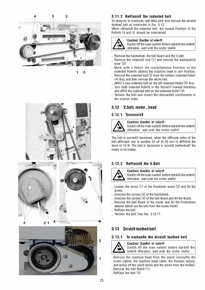
3.11.2 Replacing the indented beltTo observe: in machines with Mini-stop first remove the drivingtoothed belt as instructed in par. 3.13.When replacing the indented belt, the mutual position of thepulleys (4 and 5) should be maintained.
Caution! Danger of injury!Switch off the main switch! Before starting the settingoperation, wait until the motor stops!
- Remove the handwheel, the belt guard and the V-belt.- Remove the retaining ring (1) and remove the backtacking
lever (2).- Mark with a pencil the instantaneous position of the
indented pulleys against the machine head in any position.- Remove the indented belt (3) from the bottom indented pulley
(4) first, and then remove the whole belt.- Apply a new indented belt on the top indented pulley (5) first.- Turn both indented pulleys in the formerly marked positions
and apply the indented belt on the indented pulley (4).- Tension the belt and mount the dismantled components in
the inverse order.
3.12 V-belt, motor - head
3.12.1 Tensioning
Caution! Danger of injury!Switch off the main switch! Before starting the settingoperation, wait until the motor stops!
The belt is correctly tensioned, when the opposite sides of thebelt approach one to another by up to 20 mm in applying theforce of 10 N. The belt is tensioned in turning respectively themotor in its holder.
3.12.2 Replacing the V-Belt
Caution! Danger of injury!Switch off the main switch! before starting the settingoperation, wait until the motor stops!
- Loosen the screw (1) of the positioner arrest (2) and tilt thearrest.
- Unscrew the screws (3) of the handwheel.- Unscrew the screws (4) of the belt guard and tilt the guard.- Remove the belt guard of the motor and tilt the protections
against falling out the belt from the motor pulley.- Replace the belt.- Tension the belt (see par. 3.12.1).
3.13 Driving toothed belt
3.13.1 To exchange the driving toothed belt
Caution! Danger of injury!Switch off the main switch! before starting thesetting operation, wait until the motor stops!
- Remove the machine head from the stand (uncouple themotor cables, the machine head cable, the position sensor,and screw off the wood screw and the screw from the hinges).
- Remove the belt guard (1).- Replace the belt (2).
3 2 1 4
51
4 3 2
10 N
10 N
l - 20mm
2
1

24
3.14 Lubrication
3.14.1 DescriptionIn the main lubrication reservoir (1) there is a suction wick (2)which wipes against the shaft (3). The wick (4) collects oilfrom the shaft (3) and feeds it into the wick (5) whichdistributes oil to the lubricated spots. The left branch lubricatesthe needle and the thread mechanisms. The right branchlubricates the mechanism of the stitch length and, thereafter,pushed into the box (11). The wick (6) sucks off the excessiveoil from the needle and the thread mechanisms and alsopushed into the box (11). The lubrication reservoir (7) feedsoil through the wicks (8) for lubricating the hooks. The wick(9) lubricates the shifting wedge of the feed clutch. The wicks(10) lubricates the gears of the hooks drives.
3.14.2 Refilling oilFor lubricating the machine oil Esso SP-NK 10 is used orother oil with the same quality. When putting the machineinto operation, each mechanism of the machine is to belubricated with several drops of oil. Oil is only refilled thereafterinto the oil reservoirs using an oil can into the holes in the oillevel indicators. The oil reservoir (1) is to be filled up to thehalf of its content. The oil reservoir (2) is filled up to the pouringholes.
3.14.3 Multiple oil useOil which runs into the oil cup is collected in the collector (1) andmay be reused for refilling the oil reservoirs in the machine - seepar. 3.1.4.2.The oil collector (1) with the collected oil is uscrewed and the toppart of the oil can (2) which is added in the machine packing isscrewed in. Oil is then refilled into the reservoirs on the machinehead and everything is put into the original condition.
2
1
1
2
1
5 4 3 2
1
7 6
1 5
8
91110

25
4. Thread trimming4.1 Description of the trimming mechanismDuring the trimming cycle, the moving trimming knife (1), inan opportune moment, hooks up the sewing threads and pullsthem in the sense of the arrow (A) against the fixed knife (2)until the threads are trimmed. The spring (3) holds the hookthread after being trimmed off. The moving knife (1) is mountedon the shaft (4) which turns by means of the lever (5) underthe effect of the fork (6) fixed on the shaft (7) which is shiftedby the electromagnet (8) from its starting position in the senseof the arrow (B). When moving back in the sense of the arrow(C), the shaft (7) is shifted by the cam (9) through the pickuproller (10) into the starting position. The spring (11) maintainsthe mechanism in its starting position. The electromagnet(12), in an opportune moment, loosens the main tensioner(13). At the end of the trimming cycle, both electromagnets (8and 12) are switched off.
4.2 Setting the pickup rollerThe holder of the pickup roller (1) is to be fixed in such a way thatit is positioned, in its starting position, between the shaft (2) andthe shaft (3), the respective gap �A� = 0.2 to O.4 mm.
Caution! Danger of injury!Switch off the main switch! Before starting the settingoperation, wait until the motor stops!
- With the loosened screw (4), put the holder of the pickuproller (1) up to the stop against the bracket (5) and, at thesame time, the shaft (2) up to the stop against the shaft(3).
- With the holder (1) held on the stop, shift the shaft (2) insuch a way that there appears the gap �A� = 0.2 to 0.4 mm,and tighten the screw (4).
- Check the gap �A� in shifting the armature (6).
4.3 Setting the camThe position of the cam (1) against the shaft (2) is to be such,so that when the adjusting pin is in contact with the shaft (4),the protractor scale of the handwheel (6) shows just the angleof 108°. If the pickup roller (5) is in its starting position ofrest, the clerarance between the roller (5) and the cam (1)should be as small as possible but sufficient to prevent thecam from getting into accidental contact with the roller.
Caution! Danger of injury!Switch off the main switch! Before starting the settingoperation, wait until the motor stops!
- Set the angle of 108° on the handwheel (6) and lock it withthe screw (7) which is included in the accessory of themachine (tighten with care).
- Shift the pickup roller (5) in the sense of the arrow up to thestop.
- Insert the adjusting pin (3), which is included in the acces-sory, into the cam and turn the cam, until the pin (3) getsthe contact with the shaft (4).
- Insert a gauge having the thickness of 0.1 mm between thecam (1) and the pickup roller (2) and shift the cam againstthe gauge up to the stop. Tighten then the screw (8).
- Loosen the blocking of the handwheel, turn a bit the camand tighten the second fastening screw of the cam too.
2 3 1
4
B
C
11 10 865
12
13
97
A
2 A
1 3 64
5
513824
6
7
108o
13

26
4.4 Setting the forkIn the starting position of rest of the trimming mechanism,when the holder (1) is in contact with the bracket (2), the axisof the fork (3) must intersect the axis of the shaft (4).
Caution! Danger of injury!Switch off the main switch! Before starting the settingoperation, wait until the motor stops!
- Shift the shaft (5), until the holder (1) strikes the bracket (2).- Loosen the screw (6).- Shift the fork (3) in such a way that its axis intersects the axis of
the shaft (4).- Tighten the screw (6).
4.5 Setting the moving knifeThe moving trimming knife (1) is to be placed in its startingposition at rest with its end at the distance of the measure�A�= 0.1 to 0.5 mm from the edge of the fixed trimming knife (2).The height setting is to be such that its top surface is 1.8 mmbelow the top surface of the throat plate.
Caution! Danger of injury!Switch off the main switch! Before starting the settingoperation, wait until the motor stops!
- Loosen the screws (4 and 5).- Turn the moving trimming knife (1) in the sense of the arrow
and set it in height. Tighten the screw (5).- Turn the moving trimming knife (1) into its starting position
in such a way that the measure�A� = 0.1 to 0.5 mm isattained. Tighten the screw (4).
4.6 Setting the fixed knifeThe fixed trimming knife (1) is to be tensed up by the screw(2) in such a way that it bears on the moving trimming knife inthe 1/2 of its length. The knives need not to trim untensionedthreads.
Caution! Danger of injury!Switch off the main switch. Before starting the settingoperation, wait until the motor stops!
- Set the angle of 300° on the handwheel (4).- Shift by hand the moving knife (3) into the marked position.- By turning the screw (2), try to set the tensing up of the fixed
trimming knife (1).- Check the bearing spot of the moving trimming knife (3) on
the fixed trimming knife (1) and give it a correction, if needed.
21
563
4
4
5
1/2
1/2
2
1
3
2
1
A
4
300o
3
12
27
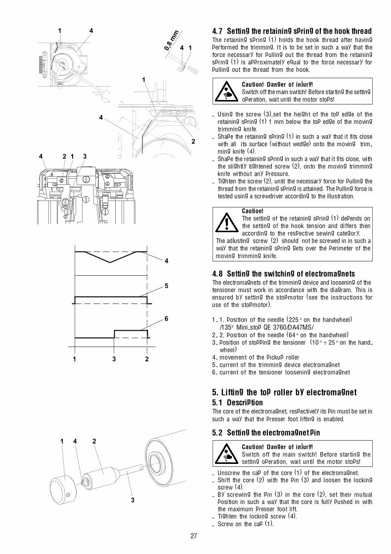
4.7 Setting the retaining spring of the hook threadThe retaining spring (1) holds the hook thread after havingperformed the trimming. It is to be set in such a way that theforce necessary for pulling out the thread from the retainingspring (1) is approximately equal to the force necessary forpulling out the thread from the hook.
Caution! Danger of injury!Switch off the main switch! Before starting the settingoperation, wait until the motor stops!
- Using the screw (3),set the height of the top edge of theretaining spring (1) 1 mm below the top edge of the movingtrimming knife.
- Shape the retaining spring (1) in such a way that it fits closewith all its surface (without wedge) onto the moving trim-ming knife (4).
- Shape the retaining spring in such a way that it fits close, withthe slightly tightened screw (2), onto the moving trimmingknife without any pressure.
- Tighten the screw (2), until the necessary force for pulling thethread from the retaining spring is attained. The pulling force istested using a screwdriver according to the illustration.
Caution!The setting of the retaining spring (1) depends onthe setting of the hook tension and differs thenaccording to the respective sewing category.
The adjusting screw (2) should not be screwed in in such away that the retaining spring gets over the perimeter of themoving trimming knife.
4.8 Setting the switching of electromagnetsThe electromagnets of the trimming device and loosening of thetensioner must work in accordance with the diagram. This isensured by setting the stopmotor (see the instructions foruse of the stopmotor).
1- 1. position of the needle (225° on the handwheel)/135o Mini-stop QE 3760/DA47MS/
2- 2. position of the needle (64° on the handwheel)3- position of stopping the tensioner (10° ÷ 25° on the hand-
wheel)4- movement of the pickup roller5- current of the trimming device electromagnet6- current of the tensioner loosening electromagnet
5. Lifting the top roller by electromagnet5.1 DescriptionThe core of the electromagnet, respectively its pin must be set insuch a way that the presser foot lifting is enabled.
5.2 Setting the electromagnet pin
Caution! Danger of injury!Switch off the main switch! Before starting thesetting operation, wait until the motor stops!
- Unscrew the cap of the core (1) of the electromagnet.- Shift the core (2) with the pin (3) and loosen the locking
screw (4).- By screwing the pin (3) in the core (2), set their mutual
position in such a way that the core is fully pushed in withthe maximum presser foot lift.
- Tighten the locking screw (4).- Screw on the cap (1).
4
5
6
1 3 2
241
3
4
14
1
2
0,8
mm41
2 314

28
5.3 Setting the electromagnet currentThe time response of the current of electromag. has 2 phases:- initial switching on (0,2 ÷ 0,5 s) - the maximum force- maintaining (when keying)
It is necessary to set max. 40 % of keying (see instru-ctions for use of the stopmotor). With a higher valuethereof and with a long period of the presser foot
in its lifted position there is a danger of electromagnetoverheating.
5.4 Aseembly of the top roller liftingelectromagnet
Caution! Danger of injury!Switch off the main switch! Before starting the settingoperation, wait until the motor stops!
- Remove the rear guard (3).- Using the screws (1), fasten the electromagnet (2) on the rear
guard (3) with the given orientation of the outlet cable (4).- Mount the rear guard (3).- Connect the outlet cable (see par.7).- Set the pin of the electromaghet (see par. 5.2).- Set the current of the electromagnet (see par.5.3).
6. Backtacking using electromagnet6.1 DescriptionThe position of the electromagnet with regard to the backtackinglever must be set in such a way that it enables the maximum stitchlength when sewing in forward and in rearward sense. If thisposition is not correct, the length of the stitch will be shortened inone or the other feed direction.
6.2 Electromagnet height setting
Caution! Danger of injury!Switch off the main switch! Before starting the settingoperation, wait until the motor stops!
- Set the maximum stitch length.- Set the position of the electromagnet (2) against the midpoint
of the grooves (1) of the guard (3).- Mount the guard (3) on the head (the bar must have a clearance
between the stop on the backtacking lever and the extreme topposition at least of 0,5 mm).
- The backtacking lever (4) is to be shifted into its bottom position(the bar (5) is to be in contact with the backtacking lever (4) ).
6.3 Setting the position of push-buttons
Caution! Danger of injury!Switch off the main switch! Before starting thesetting operation, wait until the motor stops!
- By loosening the screws (1), it is possible to set the height ofthe push-button holder.
6.4 Change of the function of push-buttonsThe Function of the push-buttons can be changed in accordancewith the possibilities given by the stopmotor (see instructionfor use of stopmotor).
1
3
4
2
12
34
5
2
1
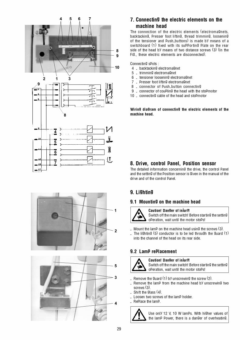
29
7. Connecting the electric elements on themachine head
The connection of the electric elements (electromagnets,backtacking, presser foot lifting, thread trimming, looseningof the tensioner and push-buttons) is made by means of aswitchboard (1) fixed with its supporting plate on the rearside of the head by means of two distance screws (3) (In theFig., these electric elements are disconnected).
Connecting spots :4 - backtacking electromagnet5 - trimming electromagnet6 - tensioner loosening electromagnet7 - presser foot lifting electromagnet8 - connector of push-button connecting9 - connector of coupling the head with the stopmotor
10 - connecting cable of the head and stopmotor
Wiring diagram of connecting the electric elements of themachine head.
8. Drive, control panel, position sensorThe detailed information concerning the drive, the control paneland the setting of the position sensor is given in the manual of thedrive and of the control panel.
9. Lighting
9.1 Mounting on the machine head
Caution! Danger of injury!Switch off the main switch! Before starting the settingoperation, wait until the motor stops!
- Mount the lamp on the machine head using the screws (3).- The lighting (5) conductor is to be led through the guard (1)
into the channel of the head on its rear side.
9.2 Lamp replacement
Caution! Danger of injury!Switch off the main switch! Before starting the settingoperation, wait until the motor stops!
- Remove the guard (1) by unscrewing the screw (2).- Remove the lamp from the machine head by unscrewing two
screws (3).- Shift the glass (4).- Loosen two screws of the lamp holder.- Replace the lamp.
Use only 12 V, 10 W lamps. With higher values ofthe lamp power, there is a danger of overheating.
4 5 6 7
10
89
2 1 3
5
3
4
1
2
9
8
4
5
6
7
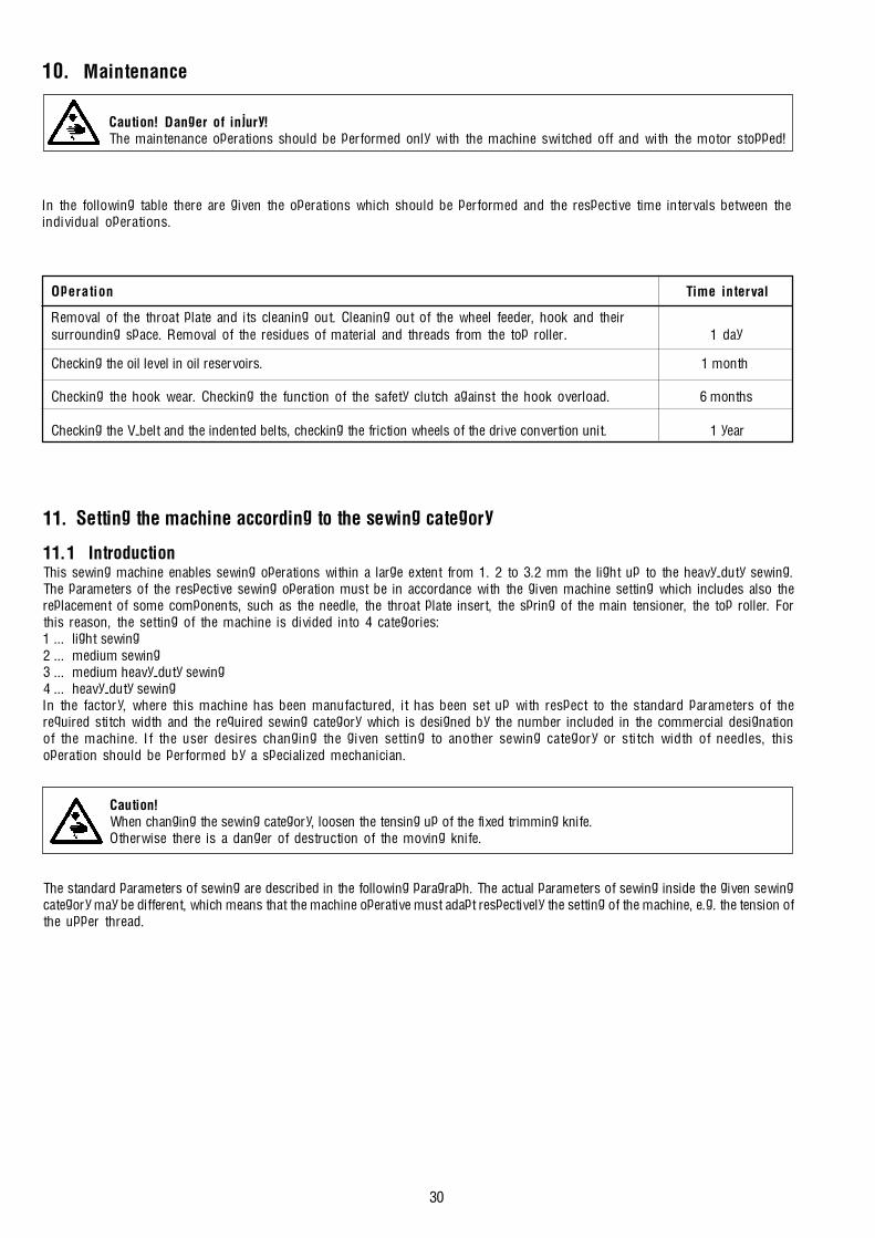
30
Operation Time interval
Removal of the throat plate and its cleaning out. Cleaning out of the wheel feeder, hook and theirsurrounding space. Removal of the residues of material and threads from the top roller. 1 day
Checking the oil level in oil reservoirs. 1 month
Checking the hook wear. Checking the function of the safety clutch against the hook overload. 6 months
Checking the V-belt and the indented belts, checking the friction wheels of the drive convertion unit. 1 year
11. Setting the machine according to the sewing category
11.1 IntroductionThis sewing machine enables sewing operations within a large extent from 1. 2 to 3.2 mm the light up to the heavy-duty sewing.The parameters of the respective sewing operation must be in accordance with the given machine setting which includes also thereplacement of some components, such as the needle, the throat plate insert, the spring of the main tensioner, the top roller. Forthis reason, the setting of the machine is divided into 4 categories:1 ... light sewing2 ... medium sewing3 ... medium heavy-duty sewing4 ... heavy-duty sewingIn the factory, where this machine has been manufactured, it has been set up with respect to the standard parameters of therequired stitch width and the required sewing category which is designed by the number included in the commercial designationof the machine. If the user desires changing the given setting to another sewing category or stitch width of needles, thisoperation should be performed by a specialized mechanician.
Caution!When changing the sewing category, loosen the tensing up of the fixed trimming knife.Otherwise there is a danger of destruction of the moving knife.
The standard parameters of sewing are described in the following paragraph. The actual parameters of sewing inside the given sewingcategory may be different, which means that the machine operative must adapt respectively the setting of the machine, e.g. the tension ofthe upper thread.
10. Maintenance
Caution! Danger of injury!The maintenance operations should be performed only with the machine switched off and with the motor stopped!
In the following table there are given the operations which should be performed and the respective time intervals between theindividual operations.
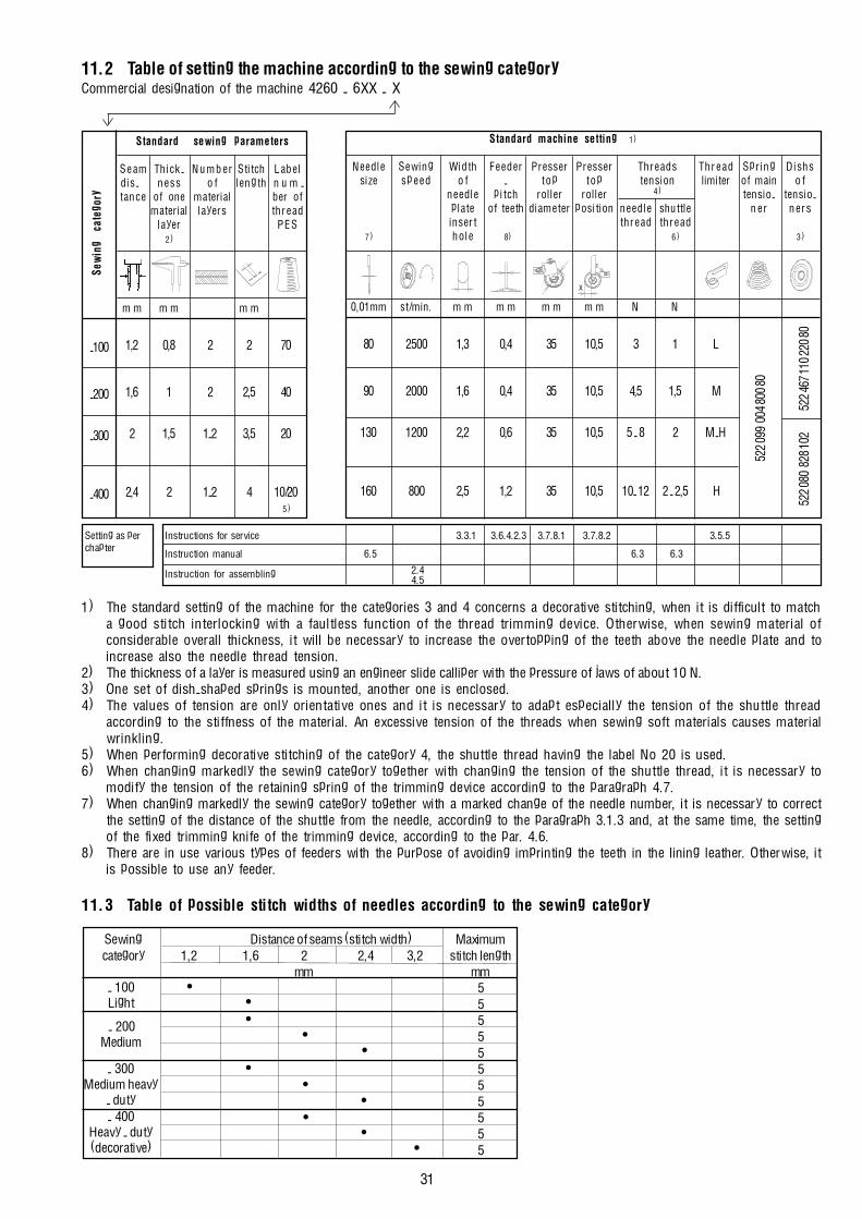
31
11.2 Table of setting the machine according to the sewing categoryCommercial designation of the machine 4260 - 6XX - X
1) The standard setting of the machine for the categories 3 and 4 concerns a decorative stitching, when it is difficult to matcha good stitch interlocking with a faultless function of the thread trimming device. Otherwise, when sewing material ofconsiderable overall thickness, it will be necessary to increase the overtopping of the teeth above the needle plate and toincrease also the needle thread tension.
2) The thickness of a layer is measured using an engineer slide calliper with the pressure of jaws of about 10 N.3) One set of dish-shaped springs is mounted, another one is enclosed.4) The values of tension are only orientative ones and it is necessary to adapt especially the tension of the shuttle thread
according to the stiffness of the material. An excessive tension of the threads when sewing soft materials causes materialwrinkling.
5) When performing decorative stitching of the category 4, the shuttle thread having the label No 20 is used.6) When changing markedly the sewing category together with changing the tension of the shuttle thread, it is necessary to
modify the tension of the retaining spring of the trimming device according to the paragraph 4.7.7) When changing markedly the sewing category together with a marked change of the needle number, it is necessary to correct
the setting of the distance of the shuttle from the needle, according to the paragraph 3.1.3 and, at the same time, the settingof the fixed trimming knife of the trimming device, according to the par. 4.6.
8) There are in use various types of feeders with the purpose of avoiding imprinting the teeth in the lining leather. Otherwise, itis possible to use any feeder.
11.3 Table of possible stitch widths of needles according to the sewing category
Sewing Distance of seams (stitch width) Maximumcategory 1,2 1,6 2 2,4 3,2 stitch length
mm mm55555555555
- 100Light
- 200Medium
- 300Medium heavy
- duty- 400
Heavy - duty(decorative)
•••
••
••
••
••
Standard machine setting 1)
Needle Sewing Width Feeder Presser Presser Threads Thread Spring Dishssize speed o f - t op top tension limiter of main o f
needle pitch roller roller 4) tensio- tensio-plate of teeth diameter position needle shuttle ne r nersinsert thread thread
7) hole 8) 6 ) 3 )
0,01mm st/min. m m m m m m m m N N
80 2500 1,3 0,4 35 10,5 3 1 L
90 2000 1,6 0,4 35 10,5 4,5 1,5 M
130 1200 2,2 0,6 35 10,5 5 - 8 2 M - H
160 800 2,5 1,2 35 10,5 10- 12 2 - 2,5 H
Standard sewing parameters
Seam Thick- Number Stitch Labeldis- ness o f length n u m -tance of one material ber of
material layers threadlayer PES
2)
m m m m m m
1,2 0,8 2 2 70
1,6 1 2 2,5 40
2 1,5 1-2 3,5 20
2,4 2 1-2 4 10/205)
-100
-200
-300
-400
522 0
99 0
04 80
0 80
522 4
67 11
0 220
8052
2 080
828
102
Setting as per Instructions for service 3.3.1 3.6.4.2.3 3.7.8.1 3.7.8.2 3.5.5chapter
Instruction manual 6.5 6.3 6.3
Instruction for assembling 2.44.5
X
Sew
ing
cate
gory