
Instructions for: Petrol Engine Twin Camshaft Setting ... · Instructions for: Petrol Engine Twin...
8
Instructions for: Petrol Engine Twin Camshaft Setting / Locking Tool Kit - (incorporating Vanos Alignment) - BMW N42 & N46 Engines Model No: VS4800 Associated kit: Camshaft/Carrier Bracket Remover & Installer Tool Kit Model No: VS4815 1. SAFETY INSTRUCTIONS Thank you for purchasing a Sealey product. Manufactured to a high standard this product will, if used according to these instructions and properly maintained, give you years of trouble free performance. IMPORTANT: PLEASE READ THESE INSTRUCTIONS CAREFULLY. NOTE THE SAFE OPERATIONALREQUIREMENTS, WARNINGS AND CAUTIONS. USE THE PRODUCT CORRECTLY AND WITH CARE FOR THE PURPOSE FOR WHICH IT IS INTENDED. FAILURE TO DO SO MAY CAUSE DAMAGE AND/OR PERSONAL INJURY AND WILL INVALIDATE THE WARRANTY. PLEASE KEEP INSTRUCTIONS SAFE FOR FUTURE USE. WARNING! Ensure Health and Safety, local authority and general workshop practice regulations are adhered to when using tools. DO NOT use tools if damaged. Maintain tools in good and clean condition for best and safest performance. Ensure that a vehicle which has been jacked up is adequately supported with axle stands. Wear approved eye protection. A full range of personal safety equipment is available from your Sealey dealer. Wear suitable clothing to avoid snagging. Do not wear jewellery and tie back long hair. Account for all tools, locking bolts, pins and parts being used and do not leave them in or near the engine. WARNING! Incorrect or out of phase camshaft timing can result in contact between valve head and piston crown causing damage to the engine. IMPORTANT: These instructions are provided as a guide only. Always refer to the vehicle manufacturer’s service instructions, or a proprietary manual, to establish the current procedure and data. 2. INTRODUCTION & APPLICATIONS 2.1 Introduction The N42 and N46 1.8 & 2.0 twin camshaft petrol engines have Vanos variable camshaft timing units on both inlet and exhaust camshafts and the BMW Valvetronic system which varies the timing and the lift of the inlet valves (Fig.1). The Valvetronic layout incorporates a conventional inlet camshaft and a secondary eccentric shaft, with intermediate levers and followers, activated by a stepper motor. The stepper motor changes the phases of the eccentric shaft, altering the action of the inlet valves. All these are housed in a camshaft carrier bracket in the cylinder head. VS4800 Engine Setting/Locking Tool Kit covers:- * Engine timing - checking and adjustment * Vanos Unit - removal, installation and alignment. VS4815 is an Associated Specialised Tool Kit which, when used in conjunction with VS4800 Kit, provides: * for removal, installation of camshafts plus dismantling and re-building of the camshaft carrier bracket / Valvetronic assembly. 2.2 Applications BMW N42 and N46 Twin Camshaft Petrol engines with Valvetronic system in: BMW: 1 Series (E87) 118i and 120i (04-), 3 Series (E46) 316i/316ti, 318i, 318Ti (01-), B18/B20 engines. VS4800 & VS4815 - 1 - 191206 VS4815 VS4800 3. CONTENTS 3.1. VS4800 Engine Setting/Locking Tool Kit: 1 VS4801 Flywheel TDC Locking Pin 2 VS4802 Camshaft Turning Tool 3 VS4803 Timing Chain Tensioner Pre-Load Tool 4 VS4804 Vanos Alignment Plate VS4805 Camshaft Setting Plate Assembly - items 5 to 7: 5 VS4805-1 Camshaft Setting Plate (Inlet) 6 VS4805-2 Camshaft Setting Plate (Exhaust) 7 VS4805-3 Camshaft Setting Plate Securing Screw -- VS4800/84 Case and Insert
Transcript of Instructions for: Petrol Engine Twin Camshaft Setting ... · Instructions for: Petrol Engine Twin...
Instructions for: Petrol Engine Twin Camshaft Setting/ Locking Tool Kit - (incorporating Vanos Alignment) -
BMW N42 & N46 Engines Model No: VS4800Associated kit: Camshaft/Carrier Bracket Remover &Installer Tool Kit Model No: VS4815
1. SAFETY INSTRUCTIONS
Thank you for purchasing a Sealey product. Manufactured to a high standard this product will, if used according to these instructions and properly maintained, give you years of trouble free performance.
IMPORTANT: PLEASE READ THESE INSTRUCTIONS CAREFULLY. NOTE THE SAFE OPERATIONAL REQUIREMENTS, WARNINGS AND CAUTIONS.USE THE PRODUCT CORRECTLY AND WITH CARE FOR THE PURPOSE FOR WHICH IT IS INTENDED. FAILURE TO DO SO MAY CAUSE DAMAGEAND/OR PERSONAL INJURY AND WILL INVALIDATE THE WARRANTY. PLEASE KEEP INSTRUCTIONS SAFE FOR FUTURE USE.
WARNING! Ensure Health and Safety, local authority and general workshop practice regulations are adhered to when using tools.DO NOT use tools if damaged.
Maintain tools in good and clean condition for best and safest performance.Ensure that a vehicle which has been jacked up is adequately supported with axle stands.Wear approved eye protection. A full range of personal safety equipment is available from your Sealey dealer.Wear suitable clothing to avoid snagging. Do not wear jewellery and tie back long hair.Account for all tools, locking bolts, pins and parts being used and do not leave them in or near the engine.WARNING! Incorrect or out of phase camshaft timing can result in contact between valve head and piston crown causing damage to the engine.
IMPORTANT: These instructions are provided as a guide only. Alwaysrefer to the vehicle manufacturer’s service instructions, or a proprietarymanual, to establish the current procedure and data.
2. INTRODUCTION & APPLICATIONS2.1 IntroductionThe N42 and N46 1.8 & 2.0 twin camshaft petrol engines have Vanosvariable camshaft timing units on both inlet and exhaust camshafts andthe BMW Valvetronic system which varies the timing and the lift of theinlet valves (Fig.1). The Valvetronic layout incorporates a conventional inlet camshaft and asecondary eccentric shaft, with intermediate levers and followers,activated by a stepper motor. The stepper motor changes the phases ofthe eccentric shaft, altering the action of the inlet valves. All these arehoused in a camshaft carrier bracket in the cylinder head.VS4800 Engine Setting/Locking Tool Kit covers:- * Engine timing - checking and adjustment* Vanos Unit - removal, installation and alignment.VS4815 is an Associated Specialised Tool Kit which, when used inconjunction with VS4800 Kit, provides:* for removal, installation of camshafts plus dismantling
and re-building of the camshaft carrier bracket / Valvetronic assembly.
2.2 ApplicationsBMW N42 and N46 Twin Camshaft Petrol engines with Valvetronicsystem in:BMW:1 Series (E87) 118i and 120i (04-),3 Series (E46) 316i/316ti, 318i, 318Ti (01-),B18/B20 engines.
VS4800 & VS4815 - 1 - 191206
VS4815
VS4800
3. CONTENTS 3.1. VS4800 Engine Setting/Locking Tool Kit:1 VS4801 Flywheel TDC Locking Pin2 VS4802 Camshaft Turning Tool3 VS4803 Timing Chain Tensioner Pre-Load Tool4 VS4804 Vanos Alignment Plate
VS4805 Camshaft Setting Plate Assembly - items 5 to 7:5 VS4805-1 Camshaft Setting Plate (Inlet)6 VS4805-2 Camshaft Setting Plate (Exhaust)7 VS4805-3 Camshaft Setting Plate Securing Screw-- VS4800/84 Case and Insert
4. INSTRUCTIONS
3.2. VS4815 Camshaft/Carrier Bracket Remover & Installer Tool Kit:
8 VS4814 Torsion Spring Remover/Installer9 VS4816 Inlet Camshaft Securing Tool (Front)10 VS4817 Inlet Camshaft Securing Tool (Rear)11 VS4818 Intermediate Lever Clamp Set (8)12 VS4819 Camshaft/Carrier Bracket Mounting Fixture-- VS4815/84 Case and Insert
SECTION 1: - Use of VS4800 Kit - Engine Timing Checking andAdjustment, and Vanos Alignment.
4.1 Checking camshaft timing
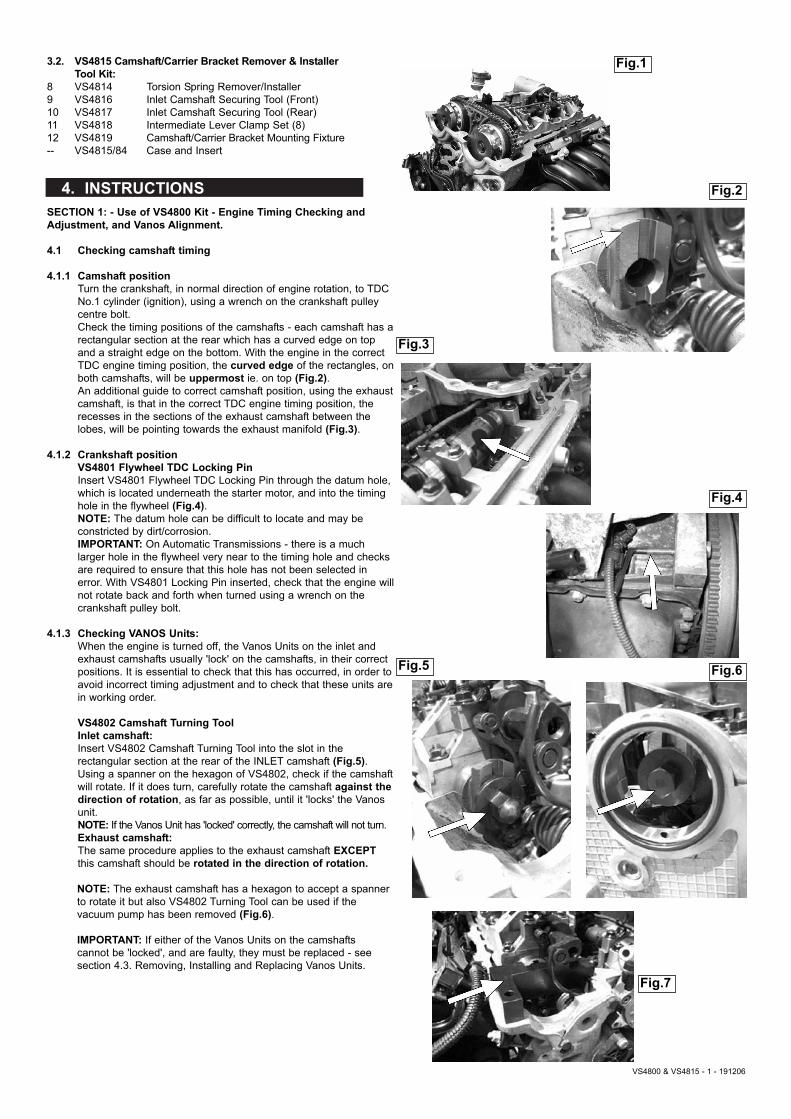
4.1.1 Camshaft positionTurn the crankshaft, in normal direction of engine rotation, to TDC No.1 cylinder (ignition), using a wrench on the crankshaft pulley centre bolt.Check the timing positions of the camshafts - each camshaft has arectangular section at the rear which has a curved edge on top and a straight edge on the bottom. With the engine in the correct TDC engine timing position, the curved edge of the rectangles, onboth camshafts, will be uppermost ie. on top (Fig.2).An additional guide to correct camshaft position, using the exhaustcamshaft, is that in the correct TDC engine timing position, the recesses in the sections of the exhaust camshaft between the lobes, will be pointing towards the exhaust manifold (Fig.3).
4.1.2 Crankshaft positionVS4801 Flywheel TDC Locking PinInsert VS4801 Flywheel TDC Locking Pin through the datum hole, which is located underneath the starter motor, and into the timing hole in the flywheel (Fig.4).NOTE: The datum hole can be difficult to locate and may be constricted by dirt/corrosion.IMPORTANT: On Automatic Transmissions - there is a much larger hole in the flywheel very near to the timing hole and checks are required to ensure that this hole has not been selected in error. With VS4801 Locking Pin inserted, check that the engine willnot rotate back and forth when turned using a wrench on the crankshaft pulley bolt.
4.1.3 Checking VANOS Units:When the engine is turned off, the Vanos Units on the inlet and exhaust camshafts usually 'lock' on the camshafts, in their correct positions. It is essential to check that this has occurred, in order toavoid incorrect timing adjustment and to check that these units arein working order.
VS4802 Camshaft Turning Tool Inlet camshaft:Insert VS4802 Camshaft Turning Tool into the slot in the rectangular section at the rear of the INLET camshaft (Fig.5).Using a spanner on the hexagon of VS4802, check if the camshaftwill rotate. If it does turn, carefully rotate the camshaft against the direction of rotation, as far as possible, until it 'locks' the Vanos unit. NOTE: If the Vanos Unit has 'locked' correctly, the camshaft will not turn.Exhaust camshaft:The same procedure applies to the exhaust camshaft EXCEPT this camshaft should be rotated in the direction of rotation.
NOTE: The exhaust camshaft has a hexagon to accept a spanner to rotate it but also VS4802 Turning Tool can be used if the vacuum pump has been removed (Fig.6).
IMPORTANT: If either of the Vanos Units on the camshafts cannot be 'locked', and are faulty, they must be replaced - see section 4.3. Removing, Installing and Replacing Vanos Units.
Fig.4
Fig.7
VS4800 & VS4815 - 1 - 191206
Fig.3
Fig.2
Fig.5 Fig.6
Fig.1
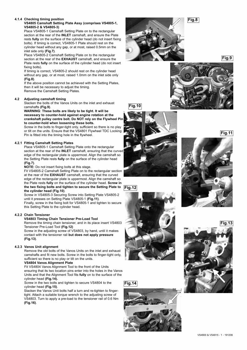
Fig.10
Fig.11
Fig.12
4.1.4 Checking timing positionVS4805 Camshaft Setting Plate Assy (comprises VS4805-1, VS4805-2 & VS4805-3)Place VS4805-1 Camshaft Setting Plate on to the rectangular section at the rear of the INLET camshaft, and ensure the Plate rests fully on the surface of the cylinder head (do not insert fixing bolts). If timing is correct, VS4805-1 Plate should rest on the cylinder head without any gap, or at most, raised 0.5mm on the inlet side only (Fig.7).Place VS4805-2 Camshaft Setting Plate on to the rectangular section at the rear of the EXHAUST camshaft, and ensure the Plate rests fully on the surface of the cylinder head (do not insert fixing bolts).If timing is correct, VS4805-2 should rest on the cylinder head without any gap, or at most, raised 1.0mm on the inlet side only (Fig.8). If the above position cannot be achieved with the Setting Plates, then it will be necessary to adjust the timing. Remove the Camshaft Setting Plates.
4.2 Adjusting camshaft timingSlacken the bolts of the Vanos Units on the inlet and exhaust camshafts (Fig.9).WARNING: These bolts are likely to be tight. It will be necessary to counter-hold against engine rotation at the crankshaft pulley centre bolt. Do NOT rely on the Flywheel Pinto counter-hold when loosening these bolts.Screw in the bolts to finger-tight only, sufficient so there is no play or tilt on the units. Ensure that the VS4801 Flywheel TDC Locking Pin is fitted into the timing hole in the flywheel.
4.2.1 Fitting Camshaft Setting PlatesPlace VS4805-1 Camshaft Setting Plate onto the rectangular section at the rear of the INLET camshaft, ensuring that the curvededge of the rectangular plate is uppermost. Align the camshaft so the Setting Plate rests fully on the surface of the cylinder head (Fig.7).NOTE: Do not insert fixing bolts at this stage.Fit VS4805-2 Camshaft Setting Plate on to the rectangular section at the rear of the EXHAUST camshaft, ensuring that the curved edge of the rectangular plate is uppermost. Align the camshaft so the Plate rests fully on the surface of the cylinder head. Screw in the two fixing bolts and tighten to secure the Setting Plate to the cylinder head (Fig.10).Screw in VS4805-3 Securing Screw into Setting Plate VS4805-2 until it presses on Setting Plate VS4805-1 (Fig.11).Finally, screw in the fixing bolt for VS4805-1 and tighten to secure this Setting Plate to the cylinder head.
4.2.2 Chain TensionerVS4803 Timing Chain Tensioner Pre-Load ToolRemove the timing chain tensioner, and in its place insert VS4803 Tensioner Pre-Load Tool (Fig.12)Screw in the adjusting screw of VS4803, by hand, until it makes contact with the tensioner rail but does not apply pressure(Fig.13).
4.2.3 Vanos Unit alignmentRemove the old bolts of the Vanos Units on the inlet and exhaust camshafts and fit new bolts. Screw in the bolts to finger-tight only, sufficient so there is no play or tilt on the units.VS4804 Vanos Alignment PlateFit VS4804 Vanos Alignment Tool to the front of the Units ensuring that its two location pins enter into the holes in the VanosUnits and that the Alignment Tool fits fully on to the surface of the cylinder head (Fig.14). Screw in the two bolts and tighten to secure VS4804 to the cylinder head (Fig.15).Slacken the Vanos Unit bolts half a turn and re-tighten to finger-tight. Attach a suitable torque wrench to the adjusting screw of VS4803. Turn to apply a pre-load to the tensioner rail of 0.6 Nm(Fig.16).
VS4800 & VS4815 - 1 - 191206
Fig.8
Fig.9
Fig.13
Fig.14
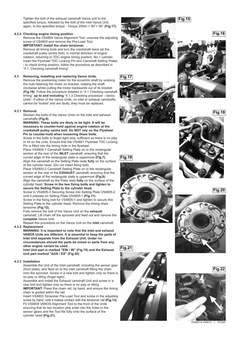
Tighten the bolt of the exhaust camshaft Vanos unit to the specified torque, followed by the bolt of the inlet Vanos Unit, again, to the specified torque - Torque 20Nm + 90°+ 90° (Fig.17).
4.2.4 Checking engine timing positionRemove the VS4804 Vanos Alignment Tool, unscrew the adjustingscrew of VS4803 and remove the Pre-Load Tool.IMPORTANT: Install the chain tensioner.Remove all timing tools and turn the crankshaft twice (at the crankshaft pulley centre bolt), in normal direction of engine rotation, returning to TDC engine timing position, No.1 cylinder.Insert the Flywheel TDC Locking Pin and Camshaft Setting Plates- to check timing position, follow the procedure as described in “4.1. Checking camshaft timing”.
4.3 Removing, installing and replacing Vanos Units.Remove the positioning motor for the eccentric shaft by undoing the nuts retaining the motor on bracket, rotating the shaft clockwise whilst pulling the motor backwards out of its bracket (Fig.18). Follow the procedure detailed in “4.1 Checking camshafttiming” up to and including “4.1.3 Checking procedure - Vanos Units”. If either of the Vanos Units, on inlet or exhaust camshafts, cannot be 'locked' and are faulty, they must be replaced.
4.3.1 RemovalSlacken the bolts of the Vanos Units on the inlet and exhaust camshafts (Fig.9).WARNING: These bolts are likely to be tight. It will be necessary to counter-hold against engine rotation at the crankshaft pulley centre bolt. Do NOT rely on the Flywheel Pin to counter-hold when loosening these bolts.Screw in the bolts to finger-tight only, sufficient so there is no play or tilt on the units. Ensure that the VS4801 Flywheel TDC LockingPin is fitted into the timing hole in the flywheel.Place VS4805-1 Camshaft Setting Plate on to the rectangular section at the rear of the INLET camshaft, ensuring that the curved edge of the rectangular plate is uppermost (Fig.7).Align the camshaft so the Setting Plate rests fully on the surface of the cylinder head. (Do not insert fixing bolt).Place VS4805-2 Camshaft Setting Plate on to the rectangular section at the rear of the EXHAUST camshaft, ensuring that the curved edge of the rectangular plate is uppermost (Fig.8).Align the camshaft so the Plate rests fully on the surface of the cylinder head. Screw in the two fixing bolts and tighten to secure the Setting Plate to the cylinder head.Screw in VS4805-3 Securing Screw into Setting Plate VS4805-2 until it presses on Setting Plate VS4805-1 (Fig.11).Screw in the fixing bolt for VS4805-1 and tighten to secure this Setting Plate to the cylinder head. Remove the timing chain tensioner (Fig.12),Fully remove the bolt of the Vanos Unit on the exhaustcamshaft. Lift chain off the sprocket and feed out and remove the complete Vanos Unit.Repeat this procedure on the Vanos Unit on the inlet camshaft.
4.3.2 ReplacementWARNING: It is important to note that the Inlet and exhaust VANOS Units are different. It is essential to keep the parts of Inlet Unit separate from the Exhaust Unit. Under no circumstances should the parts be mixed or parts from any other engine variant be used.Inlet Unit part is marked "EIN / IN" (Fig.19) and the Exhaust Unit part marked "AUS / EX" (Fig.20)
4.3.3 InstallationAssemble the Unit of the Inlet camshaft, including the sensor gear(front plate), and feed on to the inlet camshaft fitting the chain onto the sprocket. Screw in a new bolt and tighten only so there isno play or tilting (finger-tight).Assemble and install the Exhaust camshaft Unit and screw in a new bolt and tighten only so there is no play or tilting.IMPORTANT: Press the chain rail, by hand, and ensure the timingchain is guided within the rail.Insert VS4803 Tensioner Pre-Load Tool and screw in the adjustingscrew by hand, until it makes contact with the tensioner rail (Fig.13).Fit VS4804 VANOS Alignment Tool to the front of the Units ensuring that its two location pins enter into the holes in the sensor gears and the Tool fits fully onto the surface of the cylinder head (Fig.21).
VS4800 & VS4815 - 1 - 191206
Fig.17
Fig.16
Fig.15
Fig.18
Fig.19
Fig.20
Fig.21
Fig.22
VS4800 & VS4815 - 1 - 191206
Screw in the two bolts to secure VS4804 Tool to the cylinder head and tighten (Fig.15). Unscrew the bolts of the Vanos Units half turn and then tighten to finger-tight, ensuring that there is no play or tilting of the Vanosunits.Attach a suitable torque wrench to the adjusting screw of AST4803and turn to pre-load the tensioner rail to 0.6 Nm (Fig.16).Tighten the bolt of the exhaust camshaft Vanos unit to the specified torque, followed by the bolt of the inlet Vanos Unit, again, to the specified torque - Torque 20Nm + 90° + 90°. (Fig.17)
4.3.4 Checking engine timing positionRemove VS4804 Alignment Tool, Unscrew the adjusting screw of VS4803 and remove the Pre-Load ToolIMPORTANT: Install the chain tensioner.Remove all timing tools and turn the crankshaft twice (at crankshaft pulley centre bolt), in normal direction of engine rotation, returning to TDC engine timing position, No.1 cylinder.Insert the Flywheel TDC Locking Pin and Camshaft Setting Plates to check timing position as described in "4.1 Checking camshaft timing".
SECTION 2: - use of VS4815 Kit - Removing and Installing Camshaft/Carrier BracketRemoval, installation plus dis-assembly and re-building the camshafts/carrier bracket assembly requires Kit VS4815 used in conjunction with VS4800 Engine Setting/Locking Tool Kit. The Carrier, Inlet Camshaft and Eccentric Shaft must be "clamped" together and removed from the cylinder head as one assembly, prior to further dis-assembly being carried out on the workbench fixture. VS4815 Camshaft/Carrier Bracket Remover & Installer Tool Kit ComprisesVS4814 Torsion Spring Remover/InstallerVS4816 Inlet Camshaft Securing Tool (Front)VS4817 Inlet Camshaft Securing Tool (Rear)VS4818 Intermediate Lever Clamp Set (8)VS4819 Camshaft/Carrier Bracket Mounting Fixture
4.4 Dis-assembly and removal of the Camshaft/Carrier Bracket
4.4.1 Preparing for removal of the Carrier Assembly
IMPORTANT: In order to remove the Inlet camshaft and carrier assembly the Vanos Units must be removed - for procedure, refer to “4.3 Removing, Installing and replacing Vanos Units" and follow procedure for "Removal".NOTE: In following procedure for removal of the Vanos Units at this point, the Camshaft Setting Plate Assembly will be installed.Detach the pulse generator plug for the inlet camshaft (Fig.22).Remove the access plug (for lower screw of the chain guide) and unscrew and remove the chain guide screw (Fig.23 & Fig.24).NOTE: Ensure screwdriver has a firm attachment to the screw as itis withdrawn, as screw can fall into the engine.Unscrew and remove the upper screw of the chain guide (Fig.25).Remove the chain guide. NOTE: Guide is held in place by 4 lugs and will need to be carefullycompressed to release the lugs, for removal of the guide.Unscrew and remove the banjo bolt of the oil supply pipe (exhaust camshaft). (This is so the pipe can be pushed backwards and out of the way, once the Camshaft Setting Plate Assembly has been removed), (Fig.26).Remove complete VS4805 Camshaft Setting Plate Assembly and push the oil supply pipe towards the rear, approx 20mm (Fig.27).Rotate the eccentric shaft, via the hexagon, to reduce the amount of tension on the torsion spring and fit a cable tie to the spring (Fig.28).Pull the spring back slightly to lift it off its roller (Fig.29), and then allow the spring to move slowly forward and passed the roller, to relieve the tension (Fig.30).IMPORTANT: Rotate the eccentric shaft, at the hexagon provided, to minimum stroke position - turn fully clockwise.
Fig.23
Fig.24
Fig.25
Fig.26
Fig.27
Fig.28
Fig.29
Fig.30
Fig.31
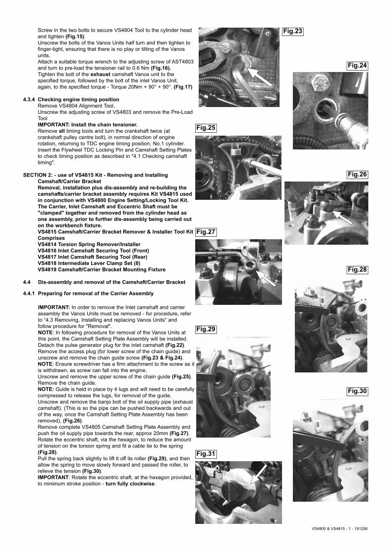
4.4.2 Securing the camshaft to the carrier bracket assemblyWARNING: Risk of injury and engine damage - This part of the application involves the removal of the camshaft carrier bracket and inlet camshaft assembly which incorporates heavy torsion springs under compression. This should not be attempted without the use of the specialised tools in VS4815 Kit, and the service procedure should be strictly adhered to.VS4816 Inlet Camshaft Securing Tool (Front)VS4817 Inlet Camshaft Securing Tool (Rear)Securing tools VS4816 and VS4817are used to retain the inlet camshaft to the carrier bracket assembly when it is being removed from the cylinder head.Fit VS4816 Camshaft Securing Tool (Front) onto the front of the inlet camshaft ensuring it locates fully and correctly onto 'lip' of the cylinder head and secure in place with its locking screw fully screwed into the internal thread in the end of the camshaft (Fig.31). Fit VS4817 Camshaft Securing Tool (Rear) on to the back of the inlet camshaft by screwing its locking bolt into the internal thread inthe end of the eccentric shaft (pinch tight only at first) and locating the 'domed' nut attached to the end of its locking screw, into the large countersink of the hole in the rectangular section in the rear of the inlet camshaft. Tighten the 'domed nut' screw, by hand, to 'lock' the tool onto the camshaft. Tighten the locking bolt into the eccentric shaft (Fig.32).
4.4.3 Clamping of the Torsion SpringsWARNING: Prior to releasing the nuts retaining the carrier bracket, the intermediate levers MUST BE secured in position.VS4818 Intermediate Levers Clamp Set (8 per set)All 8 x Clamps of VS4818 Set MUST BE fitted. Attach the Clamps to the bottom of the levers and secure the top of the Clamps onto the oil supply pipe (Fig.33).WARNING: Ensure ALL Intermediate Levers are securely clamped.
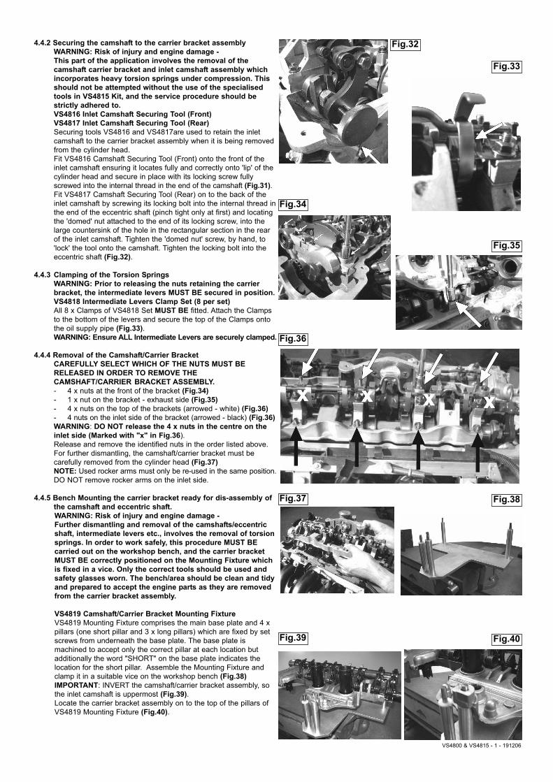
4.4.4 Removal of the Camshaft/Carrier BracketCAREFULLY SELECT WHICH OF THE NUTS MUST BE RELEASED IN ORDER TO REMOVE THE CAMSHAFT/CARRIER BRACKET ASSEMBLY. - 4 x nuts at the front of the bracket (Fig.34)- 1 x nut on the bracket - exhaust side (Fig.35)- 4 x nuts on the top of the brackets (arrowed - white) (Fig.36)- 4 nuts on the inlet side of the bracket (arrowed - black) (Fig.36)WARNING: DO NOT release the 4 x nuts in the centre on the inlet side (Marked with "x" in Fig.36).Release and remove the identified nuts in the order listed above.For further dismantling, the camshaft/carrier bracket must be carefully removed from the cylinder head (Fig.37)NOTE: Used rocker arms must only be re-used in the same position.DO NOT remove rocker arms on the inlet side.
4.4.5 Bench Mounting the carrier bracket ready for dis-assembly of the camshaft and eccentric shaft.WARNING: Risk of injury and engine damage - Further dismantling and removal of the camshafts/eccentric shaft, intermediate levers etc., involves the removal of torsion springs. In order to work safely, this procedure MUST BE carried out on the workshop bench, and the carrier bracket MUST BE correctly positioned on the Mounting Fixture which is fixed in a vice. Only the correct tools should be used and safety glasses worn. The bench/area should be clean and tidy and prepared to accept the engine parts as they are removed from the carrier bracket assembly.
VS4819 Camshaft/Carrier Bracket Mounting FixtureVS4819 Mounting Fixture comprises the main base plate and 4 x pillars (one short pillar and 3 x long pillars) which are fixed by set screws from underneath the base plate. The base plate is machined to accept only the correct pillar at each location but additionally the word "SHORT" on the base plate indicates the location for the short pillar. Assemble the Mounting Fixture and clamp it in a suitable vice on the workshop bench (Fig.38)IMPORTANT: INVERT the camshaft/carrier bracket assembly, so the inlet camshaft is uppermost (Fig.39).Locate the carrier bracket assembly on to the top of the pillars of VS4819 Mounting Fixture (Fig.40).
Fig.32
Fig.33
Fig.34
Fig.35
Fig.36
Fig.37 Fig.38
Fig.39 Fig.40
VS4800 & VS4815 - 1 - 191206
4.4.6 Removal of the Torsion SpringsWARNING: Whilst the torsion springs are still installed, Securing Tools VS4816 and VS4817 which are retaining the inlet camshaft MUST NOT be removed.Only after ALL the torsion springs have been de-tensioned and removed can the inlet camshaft be safely removed.Remove each of the torsion springs in turn and whilst removing thespring, also remove the Intermediate Lever. Store in strict order so they are re-fitted to the same cylinder position when re-assembling. Used Intermediate Levers can only be reused in the same position.
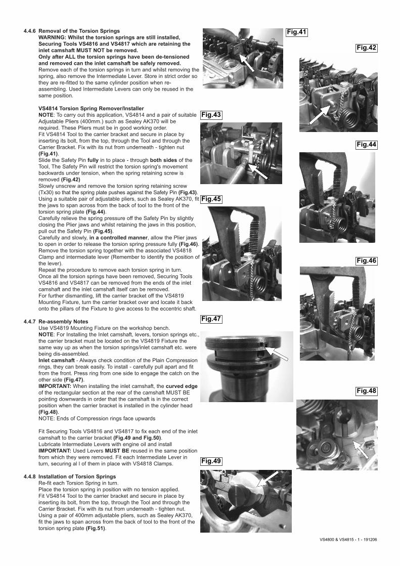
VS4814 Torsion Spring Remover/InstallerNOTE: To carry out this application, VS4814 and a pair of suitable Adjustable Pliers (400mm.) such as Sealey AK370 will be required. These Pliers must be in good working order.Fit VS4814 Tool to the carrier bracket and secure in place by inserting its bolt, from the top, through the Tool and through the Carrier Bracket. Fix with its nut from underneath - tighten nut (Fig.41).Slide the Safety Pin fully in to place - through both sides of the Tool, The Safety Pin will restrict the torsion spring's movement backwards under tension, when the spring retaining screw is removed (Fig.42)Slowly unscrew and remove the torsion spring retaining screw (Tx30) so that the spring plate pushes against the Safety Pin (Fig.43).Using a suitable pair of adjustable pliers, such as Sealey AK370, fitthe jaws to span across from the back of tool to the front of the torsion spring plate (Fig.44). Carefully relieve the spring pressure off the Safety Pin by slightly closing the Plier jaws and whilst retaining the jaws in this position, pull out the Safety Pin (Fig.45). Carefully and slowly, in a controlled manner, allow the Plier jaws to open in order to release the torsion spring pressure fully (Fig.46).Remove the torsion spring together with the associated VS4818 Clamp and intermediate lever (Remember to identify the position ofthe lever).Repeat the procedure to remove each torsion spring in turn.Once all the torsion springs have been removed, Securing Tools VS4816 and VS4817 can be removed from the ends of the inlet camshaft and the inlet camshaft itself can be removed.For further dismantling, lift the carrier bracket off the VS4819 Mounting Fixture, turn the carrier bracket over and locate it back onto the pillars of the Fixture to give access to the eccentric shaft.
4.4.7 Re-assembly NotesUse VS4819 Mounting Fixture on the workshop bench.NOTE: For Installing the Inlet camshaft, levers, torsion springs etc.,the carrier bracket must be located on the VS4819 Fixture the same way up as when the torsion springs/inlet camshaft etc. were being dis-assembled.Inlet camshaft - Always check condition of the Plain Compression rings, they can break easily. To install - carefully pull apart and fit from the front. Press ring from one side to engage the catch on theother side (Fig.47).IMPORTANT: When installing the inlet camshaft, the curved edgeof the rectangular section at the rear of the camshaft MUST BE pointing downwards in order that the camshaft is in the correct position when the carrier bracket is installed in the cylinder head (Fig.48).NOTE: Ends of Compression rings face upwards
Fit Securing Tools VS4816 and VS4817 to fix each end of the inlet camshaft to the carrier bracket (Fig.49 and Fig.50).Lubricate Intermediate Levers with engine oil and installIMPORTANT: Used Levers MUST BE reused in the same position from which they were removed. Fit each Intermediate Lever in turn, securing al l of them in place with VS4818 Clamps.
4.4.8 Installation of Torsion SpringsRe-fit each Torsion Spring in turn.Place the torsion spring in position with no tension applied.Fit VS4814 Tool to the carrier bracket and secure in place by inserting its bolt, from the top, through the Tool and through the Carrier Bracket. Fix with its nut from underneath - tighten nut.Using a pair of 400mm adjustable pliers, such as Sealey AK370,fit the jaws to span across from the back of tool to the front of the torsion spring plate (Fig.51).
Fig.43
Fig.44
Fig.45
Fig.46
Fig.47
Fig.48
Fig.49
Fig.41
Fig.42
VS4800 & VS4815 - 1 - 191206
01284 75750001284 703534 [email protected]
Sole UK DistributorSealey Group,Bury St. Edmunds, Suffolk.
www.sealey.co.ukWeb
NOTE: It is our policy to continually improve products and as such we reserve the right to alter data, specifications and component parts without prior notice.
IMPORTANT: No liability is accepted for incorrect use of this product. WARRANTY: Guarantee is 12 months from purchase date, proof of which will be required for any claim. INFORMATION: For a copy of our latest catalogue and promotions call us on 01284 757525 and leave your full name and address, including postcode.
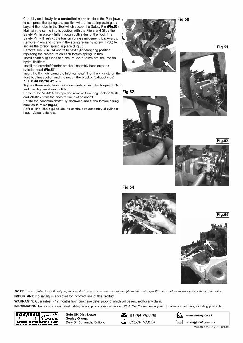
Carefully and slowly, in a controlled manner, close the Plier jaws to compress the spring to a position where the spring plate goes beyond the holes in the Tool which accept the Safety Pin (Fig.52). Maintain the spring in this position with the Pliers and Slide the Safety Pin in place - fully through both sides of the Tool, The Safety Pin will restrict the torsion spring's movement, backwards.Remove Pliers and screw in the spring retaining screw (Tx30) to secure the torsion spring in place (Fig.53).Remove Tool VS4814 and fit to next cylinder/spring position, repeating the procedure on each torsion spring, in turn.Install spark plug tubes and ensure rocker arms are secured on hydraulic lifters.Install the camshaft/carrier bracket assembly back onto the cylinder head (Fig.54).Insert the 8 x nuts along the inlet camshaft line, the 4 x nuts on thefront bearing section and the nut on the bracket (exhaust side) ALL FINGER-TIGHT only.Tighten these nuts, from inside outwards to an initial torque of 5Nmand then tighten down to 10Nm.Remove the VS4818 Clamps and remove Securing Tools VS4816 and VS4817 from the ends of the inlet camshaft.Rotate the eccentric shaft fully clockwise and fit the torsion spring back on to roller (fig.55).Refit oil line, chain guide etc., to continue re-assembly of cylinder head, Vanos units etc.
Fig.54
Fig.55
Fig.52
Fig.53
Fig.51
Fig.50
VS4800 & VS4815 - 1 - 191206