INSTRUCTIONS AND PARTS LIST SHAW-BOX Rope Electric Hoists. Page 2 12578 Figure A. ... For...
20
SHA SHA SHA SHA SHAW-BO -BO -BO -BO -BOX LIFT-TECH INTERNATIONAL Division of Columbus McKinnon MUSKEGON, MICHIGAN 49443 APRIL, 1993 COPYRIGHT 1991, LIFT-TECH INTERNATIONAL, INC. PART NO. 113533-76 INSTRUCTIONS INSTRUCTIONS INSTRUCTIONS INSTRUCTIONS INSTRUCTIONS AND AND AND AND AND P PAR AR AR AR ARTS LIST TS LIST TS LIST TS LIST TS LIST SHA SHA SHA SHA SHAW W W-BO -BO -BO -BO -BOX X X ® MOTOR DRIVEN MOTOR DRIVEN MOTOR DRIVEN MOTOR DRIVEN MOTOR DRIVEN TRA TRA TRA TRA TRAVERSE ARRANGEMENT VERSE ARRANGEMENT VERSE ARRANGEMENT VERSE ARRANGEMENT VERSE ARRANGEMENT For 5 thr For 5 thr For 5 thr For 5 thr For 5 thru 10 T u 10 T u 10 T u 10 T u 10 Ton on on on on Series 700 Deck Mounted Series 700 Deck Mounted Series 700 Deck Mounted Series 700 Deck Mounted Series 700 Deck Mounted Wir ir ir ir ire Rope Electric Hoists e Rope Electric Hoists e Rope Electric Hoists e Rope Electric Hoists e Rope Electric Hoists
Transcript of INSTRUCTIONS AND PARTS LIST SHAW-BOX Rope Electric Hoists. Page 2 12578 Figure A. ... For...

SHASHASHASHASHAWWWWW-BO-BO-BO-BO-BOXXXXXLIFT-TECH INTERNATIONALDivision of Columbus McKinnonMUSKEGON, MICHIGAN 49443
APRIL, 1993 COPYRIGHT 1991, LIFT-TECH INTERNATIONAL, INC. PART NO. 113533-76
INSTRUCTIONSINSTRUCTIONSINSTRUCTIONSINSTRUCTIONSINSTRUCTIONSANDANDANDANDAND
PPPPPARARARARARTS LISTTS LISTTS LISTTS LISTTS LIST
SHASHASHASHASHAWWWWW-BO-BO-BO-BO-BOXXXXX ®
MOTOR DRIVENMOTOR DRIVENMOTOR DRIVENMOTOR DRIVENMOTOR DRIVENTRATRATRATRATRAVERSE ARRANGEMENTVERSE ARRANGEMENTVERSE ARRANGEMENTVERSE ARRANGEMENTVERSE ARRANGEMENT
For 5 thrFor 5 thrFor 5 thrFor 5 thrFor 5 thru 10 Tu 10 Tu 10 Tu 10 Tu 10 Tononononon
Series 700 Deck MountedSeries 700 Deck MountedSeries 700 Deck MountedSeries 700 Deck MountedSeries 700 Deck Mounted
WWWWWiririririre Rope Electric Hoistse Rope Electric Hoistse Rope Electric Hoistse Rope Electric Hoistse Rope Electric Hoists

Page 2
1257
8
Fig
ure
A.

Page 3
THE INFORMATION CONTAINED IN THIS MANUAL ISFOR INFORMATIONAL PURPOSES ONLY AND LIFT-TECH INTERNATIONAL, INC. DOES NOT WARRANTOR OTHERWISE GUARANTEE (IMPLIEDLY OR EX-PRESSLY) ANYTHING OTHER THAN THE COM-PONENTS THAT LIFT-TECH MANUFACTURES AND AS-SUMES NO LEGAL RESPONSIBILITY (INCLUDING,BUT NOT LIMITED TO CONSEQUENTIAL DAMAGES)FOR INFORMATION CONTAINED IN THIS MANUAL.
TO BUILD MOTOR DRIVEN TRAVERSEARRANGEMENT
GENERAL
The following items are required for assembly of the tra-verse arrangement: One Series 700 deck mounted wirerope electric hoist, one driver truck, one trailer truck, onegear box and one motor, an optional brake may be fur-nished. The builder will have to furnish the material re-quired for mounting the electrical enclosure and, if re-quired, material for mounting a resistor. The resistor isrequired for three speed hoists only.
The builder must also furnish a means of supplying powerto the traverse. This will be collectors, festooned cable orcable reel.
MOUNTING HOIST
Although some traverse trucks have more than one set ofmounting holes for the hoist, the specified hoist will matchonly one set of holes.
Place trucks, with mounting pads up, on supports thatallow the wheels to hang free. Orient the trucks as shownin Figure A. With the gear case note (stenciled on trucks)at the same end of both trucks, the driver truck is on theright as the traverse is viewed from the gear case side.
Lower the hoist, with the gear case side properly orientedto the notes on the trucks, onto the trucks, adjusting thedistance between the trucks to match the hoist mounting
Figure B.
holes. Bolt hoist down with hardware furnished with trucks.See Figure B.
MOUNTING CONTROL PANEL
Refer to Figure C. If hoist is single or two speed, builderneed supply only item A and four bolts, lockwashers andnuts (item H, J and K) for securing control panel.
For a three speed hoist, all the material listed in Figure Cis required. The additional material is required for thesecondary resistor.
Using first quality steel, free of rust and mill scale, fabri-cate the required material and assemble on the trailertruck as shown on Figure C. It is strongly recommendedthat any welding be done by qualified welders.
The control module for traverse control is mounted in thecontrol panel.
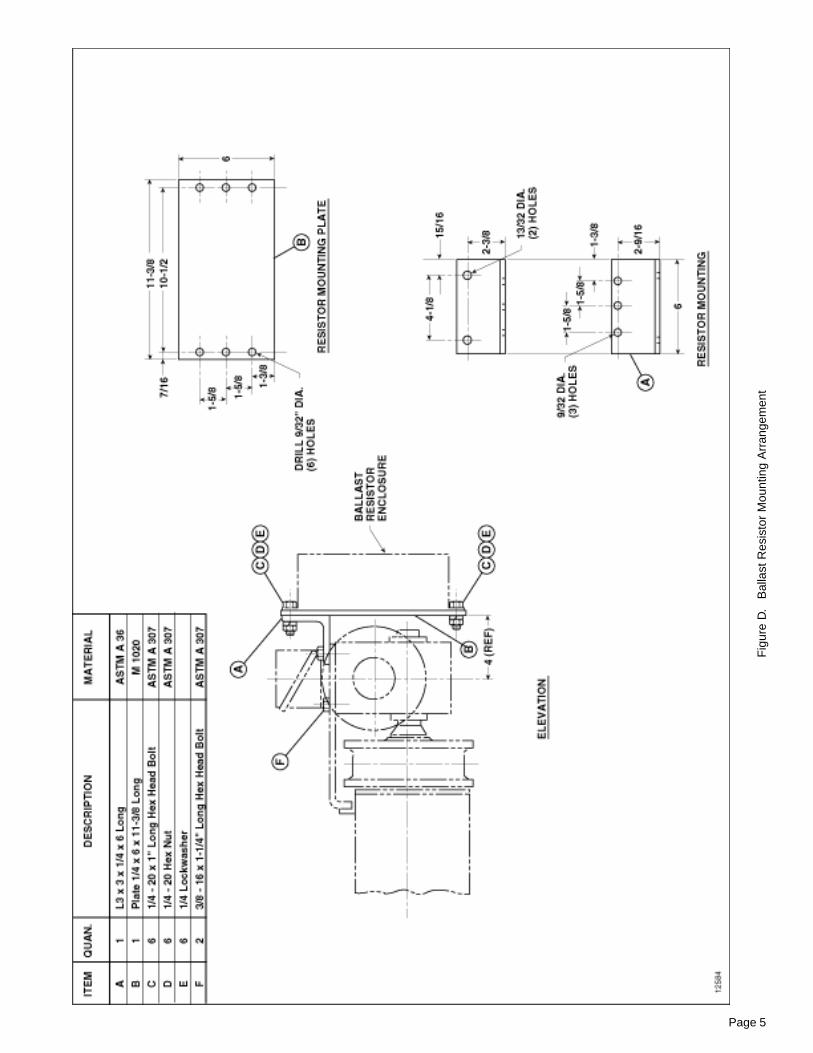
BALLAST RESISTOR MOUNTING – OPTIONAL
The ballast resistor for the traverse is an optional item. Ifordered, all material listed in Figure D is required formounting and must be furnished by the builder.
Using first quality steel, free of rust and mill scale, fabri-cate the required material, and then assemble the mate-rial on the traverse gear case unit as shown in Figure D.
ELECTRICAL
The traverse wiring diagrams are shown in 113533-78.

Page 4
Fig
ure
C.
Ele
ctric
al E
nclo
sure
and
Res
isto
r M
ount
ing
Arr
ange
men
t
Page 5
Fig
ure
D.
Bal
last
Res
isto
r M
ount
ing
Arr
ange
men
t

Page 6
Consult the Manufacturer for the traverse weight and otherrequired information before attempting installation.
Before installing traverse on bridge, lock runwayconductor disconnect switch in open (poweroff) position.
Total weight of traverse and hoist should be checkedagainst lifting equipment selected for erection of traverse.
Immediately after traverse is placed on the traverse rails,check wheel flange clearances to the rail. Clearancebetween side of rail head and inside flange of wheel willbe 1/4" for a 25# ASCE traverse rail with wheel centeredon rail.
CONNECTING TRAVERSE TO ELECTRICALSERVICE: Traverse wiring diagrams are shown in113533-78.
Verify that traverse is furnished for the same voltage,frequency and phase as the traverse power supply.Do not operate traverse until “Pre-Operation Checks”below are made.
PRE-OPERATION CHECKS: After the hoist traverse unitis connected to electrical service, the following pre-operation checks should be made before operation:
1. Check collector system for proper adjustment tomaintain proper contact with conductors or check alongspan for possible interference if power supply is cable reelor festooned cable.
2. Make certain traverse stops have been installed andthat they are correctly located.
3. Check truck axles and oil level of gear box. If lubricantis required, see LUBRICATION on page 11.
4. Inspect the traverse to make certain all boltedattachments are properly tightened and all electricalconnections are secure.
5. The hoist unit should be checked as instructed in theHoist Manufacturer’s Instruction Manual. Check to makesure that traverse wheels have proper clearance to railsfor freedom of operation.
6. The traverse wheels and the flange surface of cranerails on which traverse wheels roll should be free of paintto provide proper electrical ground. If the environment inwhich the crane will operate is such as to impair thecontact between traverse wheel and crane girder, an extraconductor should be provided for grounding purposes.
NOTE: This instruction also applies to the bridgewheel and runway rail.
CAUTION
WARNING
INSTALLATION OF MOTOR DRIVENTRAVERSE ARRANGEMENT
This manual contains important information to help you tooperate, maintain, and service the traverse arrangementof your crane trolley. The hoist is covered in a separatemanual.
We recommend that you study the contents thoroughlybefore putting the traverse into use. With proper installation,application of correct operating procedures, and practicingthe recommended maintenance suggestions you will beassured maximum service from your traverse.
The traverses described in this manual are intended forindoor service. Traverses to be used for outdoor servicerequire special consideration.
IMPORTANT!
When ordering replacement parts be sure to include withyour order, the KEY NUMBERS, which are identifiedelsewhere in this manual.
Information given in this manual is subject to changewithout notice.
GENERAL DESCRIPTION
GENERAL: These traverses are designed to operate onparallel bridge girders with 25# ASCE rails. Motor andcontrol are designed for 208V, 230V, 460V or 575V – 3phase – 60 hertz power supply. The traverse is equippedwith a single or two speed motor, controlled from a pendantpush button station. The push button may be located onthe bridge or hoist traverse unit. Traverses described herein,are built in rated loads from 5 thru 10 tons.
BASIC CONSTRUCTION: The traverse frame is of rolledsteel welded construction. The frame consists of two trucksrigidly bolted to the hoist.
The traverse is driven by a motor and gear box attachedto one truck. This drives the truck axle by a hollow shaftkeyed to the axle.
INSTALLATION
GENERAL: Bridge girders on which these traverses willoperate must be amply strong to support traverse, hoistingequipment and rated load. Traverse rails should be leveland parallel within ± 1/4". Rail joints must be smooth andheld firmly in alignment either by bolted splice bars orwelding. Rails should be securely fastened to the bridgegirders.
INSTALLING: The installation of the traverse on the craneshall be performed only by qualified installer.
For information regarding attaching, lifting and moving theloads during installation, refer to ANSI B30.2.0, Section 2-3.2 and other applicable codes.
Page 7
OPERATION
OPERATOR QUALIFICATIONS: Safe and efficient craneoperation requires skill, extreme care and good judgement,alertness, concentration and knowledge of and rigidadherence to proven safety rules and practices. No personshould be permitted to operate a crane or hoist:
1. who does not possess above characteristics.
2. who is not qualified or has handicaps that couldadversely affect such operation.
3. who has not been properly instructed.
4. who has not been informed and does not have athorough knowledge of all applicable safe operatingpractices, including those in this book as well as hitchingequipment and practices.
NOTE: See applicable National, State and LocalSafety Codes and regulations for additionalrequirements relating to Safe Operating Practices,including American National Standards ANSIB30.2.0 and ANSI B30.16 as published byAmerican Society of Mechanical Engineers.
OPERATING RULES: Operating rules listed below arean earnest effort to encourage SAFETY and are notintended to take precedence over individual plant safetyrules and regulations or rules set forth by various applicablecodes.
A good operator operates his crane as smoothly aspossible and knows and follows the suggested rules belowfor safe, efficient crane handling.
Take time to become familiar with performance and allfunctions of the crane including safety devices.
Hitch loads securely. This is the joint responsibility of thehitcher and the crane operator. Never lift load withloose slings or with sling hooks attached to cranehook.
I f the brakes do not hold, do not operate crane. Reportdefect immediately to supervisor.
Never leave load hanging from crane or hoist when notattended.
Know the safe capacity of crane and chain slings, ropeslings, etc. Do not make lifts above safe capacity ofcrane or slings.
See that the immediate area is clear before moving aload. Do not lift loads over persons.
Avoid bumping other cranes on a runway unlessspecifically authorized to do so. Never move or bumpanother crane having a warning sign displayed.
First be sure to hoist load high enough to clear allworkmen and obstructions before moving bridge ortrolley.
Energize each motion gradually and avoid abrupt, jerkymovements of the load.
Take up slack from sling and hoisting cables beforelifting load.
Yield to people in a working area; allow them time to getout of danger.
Follow operating and maintenance procedures describedin manufacturer’s manuals to operate and maintainbridge, traverse and hoist.
I nspect crane frequently. Be alert for unusual or erraticconditions. Be certain the crane is SAFE to operate atall times.
Repair electrical apparatus or make other major repairsonly when specifically authorized to do so. Do notchange fuse sizes. Never attempt to close a switchhaving a “DO NOT OPERATE” sign or card attached.
Stop crane, hoist or traverse under normal operatingconditions before engaging limit switches. Limit switchesare safety devices and should not be used as a normaloperating control.
Traverse the bridge and traverse to a position directlyover the load before starting to hoist. The hoistingchain or rope should be kept vertical to avoid swingingthe load as the lift is started.
Make sure all INSTALLATION AND OPERATIONCHECKS have been made before turning on power.
LEARNING THE CONTROLS: After making certain thetraverse is completely and properly installed with traverseconnected to power supply and all pre-operation checksmade, the operator should learn the controls.
CAUTION
Page 8
Sixth – Operate traverse from one end of bridge to theother, checking for obstructions or interferences. Proceedwith CAUTION and be prepared to stop short of anyobstructions. If traverse power is interrupted during traversetravel, check traverse collectors for proper contact withbridge conductors.
Lock main runway disconnect switch in open(power off) position before attempting to adjustcross collectors or conductors.
Seventh – After making certain that all building andstructural clearances are adequate, practice going “Left”and “Right” with push button depressed. Note the stoppingdistance of the trolley without load.
After becoming familiar with these motions, the operatorcan now depress the hoist “Up” button.
If, when depressing hoist “Up” button, the hookshould lower – STOP AT ONCE – Do not attemptto operate again. Report this condition to propersupervisor for correction with instructionsfurnished with your hoist manual.
Depress the “Down” button, with hook moving downwardon multi-speed hoists, try to feel the steps in relation tospeed increase as push button is depressed further.
Hook may be lowered until TWO FULL WRAPS of cableremain on the drum. Note position of hook and NEVERLOWER HOOK BELOW THIS POSITION. (Some hoistsmay have a lower limit switch which will stop hoist whenthis position is reached. Consult Hoist Manufacturer’sManual.)
Depress the hoist “Up” button and slowly return the hookto near its high position. Continue to raise hook by slowlyinching. CAREFULLY OBSERVE the relationship of thehook block and the bottom of the hoist frame. The hoistupper limit switch, when working properly should causethe hoist up motion to stop and/or reverse direction.
Do not contact or strike hoist frame with hookblock. If hoist motion is not interrupted by limitswitch, stop hoist by removing finger frombutton and/or depressing the STOP button. Donot attempt further operation until limit switchis operable. Consult Hoist Manufacturer’sInstructions.
Repeat upper limit switch test described above at fullspeed.
WARNING
WARNING
WARNING
WARNING
The operator should locate the runway disconnect andmake sure this switch is locked open (POWER OFF). Theoperator should now operate the various push buttons toget the “feel” and determine that they do not bind or stickin any position. The operator should become familiar withpush button location for their respective motions as wellas “start” and “stop” buttons which operate the crane mainline contactor. The main line contactor will shut off powerto all motions.
If any push button binds or sticks in any position– Do not turn power on – Determine the causeof malfunction and correct before operatingcrane.
OPERATING THE CONTROLS (NO LOAD): Havinginspected and tried the pendant push button station, thecrane operator is now ready to try the crane under power.
First – Close the crane runway disconnect switch.
Second – Close the crane disconnect switch.
Third – Press the start-push button which will close themain line contactor, applying power to all control devices.The traverse is now ready for further testing.
The traverse is powered by a single or two speed motor.There is one button for each direction, labeled “Left” and“Right”. Depressing either button will cause traverse tooperate.
ALWAYS ALLOW TRAVERSE TO COME TO ACOMPLETE STOP BEFORE CHANGINGDIRECTION. ABRUPT CHANGE OF TRAVERSEDIRECTION WHILE IN MOTION, MAY CAUSEADVERSE OPERATING CHARACTERISTICS ORDAMAGE TO TRAVERSE AND DRIVECOMPONENTS.
Fourth – Momentarily depress traverse “Left” button.Check to be certain motor runs in the proper direction.Momentarily depress “Right” button. Check direction. Toreverse directions, interchange leads L1 and L2 in thetraverse panel.
Lock crane main switch open (power off) beforereversing leads.
Fifth – To check that electrical connections have beenproperly made, operate traverse cautiously on bridge.Watch for any obstructions or interferences betweentraverse and building parts. Depress “Left” button slightly– traverse will travel along bridge.
WARNING
CAUTION
Page 9
WARNING
WARNING
During this test and under any other operatingcondition – OPERATOR SHOULD NEVER BEPOSITIONED UNDER THE HOOK OR LOAD.
NOTE: Jogging is used excessively by someoperators for making “inching” crane movements.AVOID EXCESSIVE USE OF JOGGING SINCEIT MAY CAUSE PREMATURE BURNING OFCONTACT TIPS AND MOTOR OVERHEATING.
THIS EQUIPMENT IS NOT DESIGNED ORSUITABLE AS A POWER SOURCE FOR LIFTINGOR LOWERING PERSONS.
OPERATING THE CONTROLS (WITH LOAD): Makecertain hook is high enough to clear any obstructionsbelow. Move the bridge to a position directly over the load,and operate in the following sequence:
STEP 1: Spot the traverse and hoist over the load. Ifcontrol is suspended from the bridge, hand signals maybe required from ONE authorized floor man at the load.Be certain load to be lifted is properly hitched and doesnot exceed the rated capacity of the hoist, traverse orbridge.
STEP 2: Slowly raise the hook until slack has been takenout of slings. When floor man signals and operator issatisfied load is secure in sling, he lifts the load slowlyuntil clear. Now, hoisting speed can be increased andmaintained until load is clear of all obstructions or floorman gives the signal to stop.
STEP 3: Starting slowly and increasing speed as distancepermits, move the bridge toward the point where the loadis to be lowered. The stopping distance will be greaterthan with no load on the hook.
STEP 4: Learn to judge the stopping distance of thebridge and traverse, both with light loads and full loads.This will enable you to “spot” loads with the minimumamount of jogging.
NOTE: Refer to hoist manual for completeoperating instructions for hoist.
RESPONSIBILITY FOR SAFE OPERATION: Each craneoperator should be held directly responsible for the safeoperation of his crane. The crane operator should STOPthe crane and refuse to handle loads when:
1. there is any doubt as to SAFETY;
2. any unusual vibrations or sounds are noticed beforeor when starting the lift or traverse motions;
3. there are arguments or disagreements with floor manor hitchers;
4. he feels ill or is not alert.
WARNING
WARNINGINSPECTION
The crane should be inspected at the beginning of eachshift. All functional mechanisms should be in good workingorder. Check limit switches, brakes, electrical equipment,and other SAFETY devices. Check crane operation withoutload. Any unusual sounds, vibrations, anything wrong orapparently wrong should be reported to the operators’supervisor immediately. Inspect hoist as recommended inmanufacture’s hoist manual.
Do not operate a crane, hoist or traverse havingunusual vibrations, sounds, warnings or withanything wrong or apparently wrong. Dangermay be present that the crane operator cannotsee. Determine and correct cause of unusualconditions and make certain the crane can beoperated SAFELY.
Complete inspection of the crane is to be performed atleast every six months and more frequently whenconditions require. Inspect areas listed below and anyother area which may be adversely affected due to activity,severity of service and crane environment that could causeunsafe crane operation.
Always lock main switch in open (power off)position before inspection.
Items to be inspected include, but are not limited to:
1. All functional operating mechanisms for maladjustmentinterfering with crane operation.
2. Operating parts for excessive wear.
3. All safety devices for malfunction.
4. All connections and mountings for loose bolts, nuts orother fasteners for tightness.
5. All structural members for deformation, cracks,corrosion.
6. All electrical apparatus, including control contactors,limit switches, push button stations for signs of pittedcontact points, wear or deteriorations.
7. All hoists and traverses installed on the crane inaccordance with manufacture's recommendations.
Written, dated and signed inspection reports should bemaintained on all critical items (such as safety devices,brakes, hooks, ropes, chains, etc.). All worn, damaged ormalfunctioning parts should be repaired or replaced tomaintain a SAFE operating crane. Warning labels affixedto the crane, hoist or traverse should be kept clean andvisible at all times. Warning labels should be replaced ifloose or illegible. A typical inspection Schedule andMaintenance Report Form is shown on Page 10.

Page 10
INSPECTION SCHEDULE AND MAINTENANCE REPORTCRANE SERIAL NO. (MFGRS) _______________________ CUSTOMER CRANE IDENTITY NO. _______________________RATED LOAD __________________ LOCATION IN PLANT __________________________________
TYPE ________________________ THIS INSPECTION IS MONTHLY � ANNUAL �
VOLTAGE _____________________ SEMI-ANNUAL �
INSPECTED BY: ________________ DATE _____________
*Recom- CONDITIONCOMPONENT, UNIT OR PART mended (Check column best indicating condition when CORRECTIVE ACTION
and location Inspection part or unit is inspected. Use note column to NOTESInterval the right if condition is not listed below.)
MO
NTH
LY
SE
MI-A
NN
UA
L
AN
NUA
L
GO
OD
AD
JUS
TME
NT
RE
QU
IRE
D
RE
PAIR
RE
QU
IRE
D(L
oose
Par
ts o
rW
ires
)
RE
PLA
CE
ME
NT
RE
QU
IRE
D(W
orn
or D
amag
ed)
LUB
RIC
ATIO
NR
EQ
UIR
ED
(Low
Oil
or G
reas
e,R
ust o
r C
orro
sion
)
CLE
AN
ING
OR
PAIN
TIN
GR
EQ
UIR
ED
LOC
ATIO
N
COMPONENT,UNIT OR
PART
(Indicate corrective action taken during inspection and note date. Forcorrective action to be done after inspection, a designated person mustdetermine that the existing deficiency does not constitute a safety hazardbefore allowing unit to operate. When corrective action is completed,describe and note date in this column.)
DATE
Motor
Gears & Bearings
Wheels
Trucks
Girders & Connections
Footwalk & Handrail
Motor
Motor Brake
Mechanical Load Brake
Overload Clutch
Couplings
Gear, Shafts & Bearings
Upper Block
Lower Block
Hook & Throat Opening X Record Hook Throat Opening
Hoist Rope
Rope Drum
Guards
Limit Switch
Bridge Panel
Trolley Panel
Hoist Panel
Pushbutton
Wiring
Motor
Brake (when so equipped)
Couplings
Gear, Shafts & Bearings
Frame
Wheels
Bumpers
Guards
Conductors
Collectors
Monorail Joints
Monorail
Main Conductors
Main Collectors
General Condition
Load Attachment Chains
Rope Slings & Connections
Change Gearcase Lub.
Grounding Faults
HO
IST
TRO
LLE
YM
ISC
.R
UN
WAY
SC
ON
TRO
LPA
NE
LS A
ND
PU
SH
BU
TTO
NB
RID
GE
* See text for DAILY & WEEKLY REQUIREMENTS. SIGNED & DATED REPORT REQUIRED – OSHA.
INSPECTION INTERVAL. X MAGNETIC PARTICLE OR EQUIVALENT EXAMINATION REQUIRED.
Typical Inspection Schedule and Maintenance Report form.User must adjust inspection interval and components to suit his individual conditions and usage. 12382A

Page 11
MAINTENANCE
GENERAL: Maintenance services required on traversesare, for the most part, simple periodic inspections andadjustments. Procedures for lubrication, routine adjust-ments and replacement of parts, if required, are describedin the following paragraphs.
LUBRICATION: Motor bearings are lubricated for the lifeof the bearing and require no additional lubrication.
Axle bearings are lubricated for the life of the bearing andrequire no additional lubrication.
The gear box attached to the motor requires gear case oilhaving a viscosity at 210½F of 125-150 SSU, viscosityindex at 90 and a pour point of 25½F (AGMA #7 Com-pound) at an ambient temperature of 50½ to 125½F. Forambient temperatures outside this range, refer to the Manu-facturer for recommendations.
General oiling should be performed every three months toprevent rusting and provide limited lubrication for pointsnot having lubrication fittings nor considered normal wearpoints. Pins, levers, rods, hinges and other linkages andmoving parts, where rusting could occur and interferewith normal operation, should be oiled with a few drops ofoil. (Examples include, collector pins and linkage, limitswitch linkage, cable carriers, etc. Also see instructionsfurnished with hoist.)
The frequency of oil changes in the gearhead unit andaxle bearing lubrication is dependent on crane usage. Theuser should establish a lubrication interval based on indi-vidual conditions of usage and environment (includingairborne dirt, chemical dust, moisture, etc.), but this inter-val should never exceed six months. Also, drain and refillgear box after first 100 hours of operation.
For hoist lubrication instructions refer to HoistManufacturer’s Service Manual.
WHEEL REMOVAL(Refer to parts illustration, Figure 2.)
To remove wheels, follow steps 1 through 6 listed below:
1. Remove any load from hook.
Make sure that traverse is adequately supportedso that it cannot drop when wheel is removed.Also lock main runway disconnect switch inopen (power off) position when working onwheels adjacent to runway conductors.
2. Remove load from wheel axle. This can be accom-plished by jacking a small distance, just enough to clearthe wheel flanges.
3. Wheel (Ref. No. 2) is held in position by retaining ring
WARNING
WARNING
(Ref. No. 1), in a groove in the axle. Remove retainingring.
4. Wheel is now free. Remove by sliding horizontally offaxle, maintaining a secure hold so that wheel does notfall.
5. Remove key (Ref. No. 4).
6. Replace wheels in reverse procedure of disassembly.
Wheel at motor may be removed by using the aboveprocedure after the motor and gear box have been re-moved.
AXLE REMOVAL(Refer to parts illustration, Figure 2.)
To remove axle, follow steps 1 through 4 listed below:
1. Remove both wheels on truck as described above.
2. One side of truck has a retaining ring (Ref. No. 7),securing the axle bearing (Ref. No. 3). The axle (Ref. No.5) may be removed by pushing axle toward opposite sideof truck. Maintain a secure hold on the axle so that it doesnot fall.
3. If required, retaining ring may also be removed allow-ing removal of both bearings.
4. Replace axle in reverse procedure of disassembly.
It is recommended that bearings be replaced wheneverreplacing wheels or axles.
The axle at the motor may be removed by using theabove procedure after the motor and gear box have beenremoved.
GEAR BOX REMOVAL(Refer to parts illustration, Figure 1.)
Main runway disconnect switch should be lockedopen (power off) before working on gearmotor.
To remove gear box:
1. Disconnect wiring and conduit at conduit box on mo-tor.
2. Remove the four bolts and lockwashers holding thetop of the gear box to the mounting plate on the drivertruck.
3. Slide gear box and motor off axle extension takingcare not to drop it.
4. Remove key (Ref. No. 2).
5. Remove four bolts and lockwashers (Ref. Nos. 3 and4) to separate motor from gear box.
6. Reassemble in reverse.

Page 12
ELECTRICAL
Main runway disconnect switch should be lockedopen (power off) before working on electricalequipment.
1. Motors
a. The traverse is driven by a single or two speedmotor with a single worm gear box. The worm gear re-tards speed with power off and, therefore, a traverse brakeis not normally furnished.
It is recommended that if any work is required, the motorbe returned to the crane builder.
b. For hoist motor, consult the hoist literature.
WARNING
2. Traverse Control Panel
a. For wiring diagrams for traverse panel, see113533-78.
b. All connections should be checked frequently fortightness.
c. Contactors should be replaced as a completeunit.
3. Optional Brake
If brake is furnished, reference brake literature for mainte-nance and replacement.
4. Hoist Panel, Brakes, Limit Switches
Consult hoist literature for maintenance and spare partliterature.
NOTES

Page 13
REPLACEMENT PARTS
The following parts list and illustrations cover standardmodel SHAW-BOX traverses. Typical units are used as thebasis for the exploded parts illustrations; therefore, certainvariations may occur from the parts information given. Forthis reason always give the catalog number, model num-ber, motor horsepower, voltage, phase and frequency whenordering replacement parts. For motors, gear boxes, andelectrical components, give complete nameplate data.
INDEX OF PARTS ILLUSTRATIONSFigure Page
Title No. No.
Driver Truck .......................................................................................................................................... 1 14
Trailer Truck ......................................................................................................................................... 2 15
Motor and Gear Box ............................................................................................................................ 3 16
Traverse Controls for Single Speed Trolley .......................................................................................... 4 17
Traverse Controls for Two Speed Trolley .............................................................................................. 5 18
NOTES
The factory recommends complete replacement of themotor or gear box.
The numbers assigned to the parts of our variousassemblies in our parts list are not the part num-bers used in manufacturing the part. They areidentification numbers, that when given with thecatalog number, permits us to identify, select ormanufacture, and ship the correct part needed.
Page 14
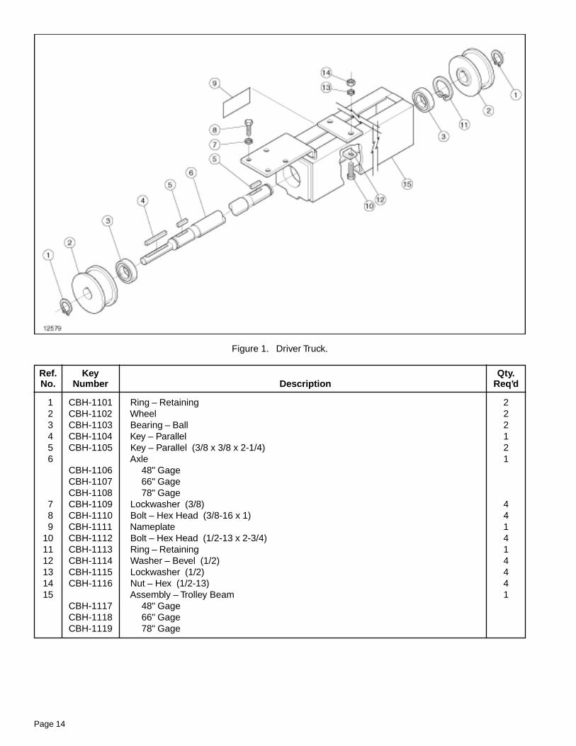
Figure 1. Driver Truck.
Ref. Key Qty.No. Number Description Req’d
1 CBH-1101 Ring – Retaining 22 CBH-1102 Wheel 23 CBH-1103 Bearing – Ball 24 CBH-1104 Key – Parallel 15 CBH-1105 Key – Parallel (3/8 x 3/8 x 2-1/4) 26 Axle 1
CBH-1106 48" GageCBH-1107 66" GageCBH-1108 78" Gage
7 CBH-1109 Lockwasher (3/8) 48 CBH-1110 Bolt – Hex Head (3/8-16 x 1) 49 CBH-1111 Nameplate 1
10 CBH-1112 Bolt – Hex Head (1/2-13 x 2-3/4) 411 CBH-1113 Ring – Retaining 112 CBH-1114 Washer – Bevel (1/2) 413 CBH-1115 Lockwasher (1/2) 414 CBH-1116 Nut – Hex (1/2-13) 415 Assembly – Trolley Beam 1
CBH-1117 48" GageCBH-1118 66" GageCBH-1119 78" Gage
Page 15
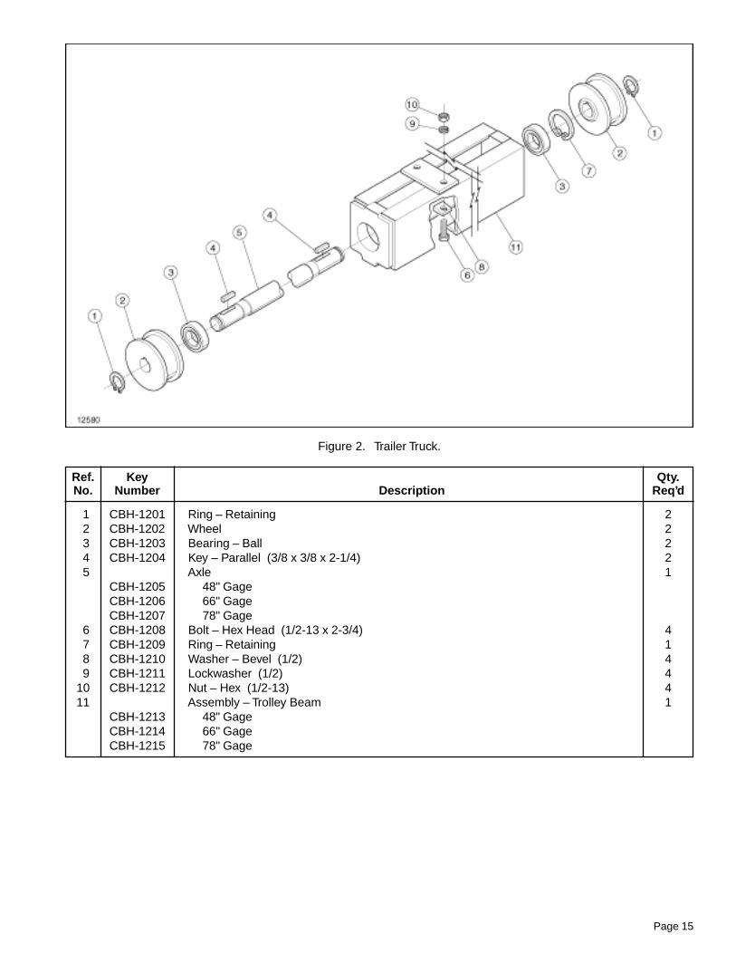
Figure 2. Trailer Truck.
Ref. Key Qty.No. Number Description Req’d
1 CBH-1201 Ring – Retaining 22 CBH-1202 Wheel 23 CBH-1203 Bearing – Ball 24 CBH-1204 Key – Parallel (3/8 x 3/8 x 2-1/4) 25 Axle 1
CBH-1205 48" GageCBH-1206 66" GageCBH-1207 78" Gage
6 CBH-1208 Bolt – Hex Head (1/2-13 x 2-3/4) 47 CBH-1209 Ring – Retaining 18 CBH-1210 Washer – Bevel (1/2) 49 CBH-1211 Lockwasher (1/2) 4
10 CBH-1212 Nut – Hex (1/2-13) 411 Assembly – Trolley Beam 1
CBH-1213 48" GageCBH-1214 66" GageCBH-1215 78" Gage
Page 16
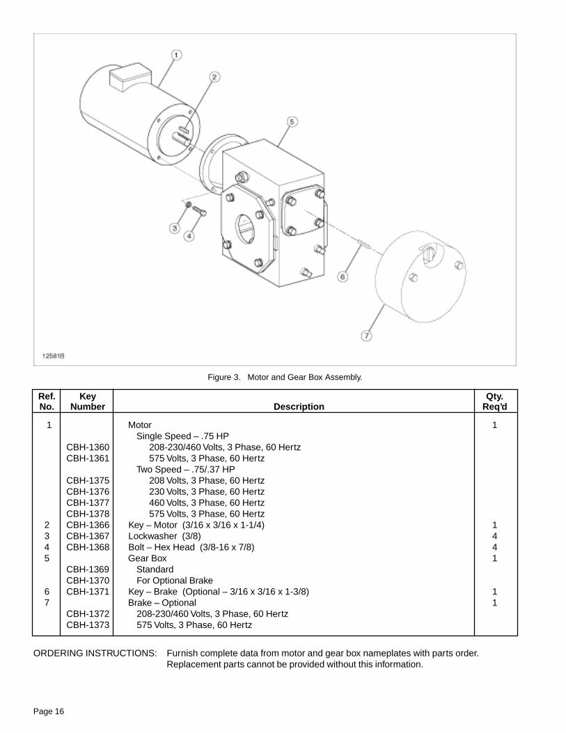
Figure 3. Motor and Gear Box Assembly.
Ref. Key Qty.No. Number Description Req’d
1 Motor 1Single Speed – .75 HP
CBH-1360 208-230/460 Volts, 3 Phase, 60 HertzCBH-1361 575 Volts, 3 Phase, 60 Hertz
Two Speed – .75/.37 HPCBH-1375 208 Volts, 3 Phase, 60 HertzCBH-1376 230 Volts, 3 Phase, 60 HertzCBH-1377 460 Volts, 3 Phase, 60 HertzCBH-1378 575 Volts, 3 Phase, 60 Hertz
2 CBH-1366 Key – Motor (3/16 x 3/16 x 1-1/4) 13 CBH-1367 Lockwasher (3/8) 44 CBH-1368 Bolt – Hex Head (3/8-16 x 7/8) 45 Gear Box 1
CBH-1369 StandardCBH-1370 For Optional Brake
6 CBH-1371 Key – Brake (Optional – 3/16 x 3/16 x 1-3/8) 17 Brake – Optional 1
CBH-1372 208-230/460 Volts, 3 Phase, 60 HertzCBH-1373 575 Volts, 3 Phase, 60 Hertz
ORDERING INSTRUCTIONS: Furnish complete data from motor and gear box nameplates with parts order.Replacement parts cannot be provided without this information.
Page 17
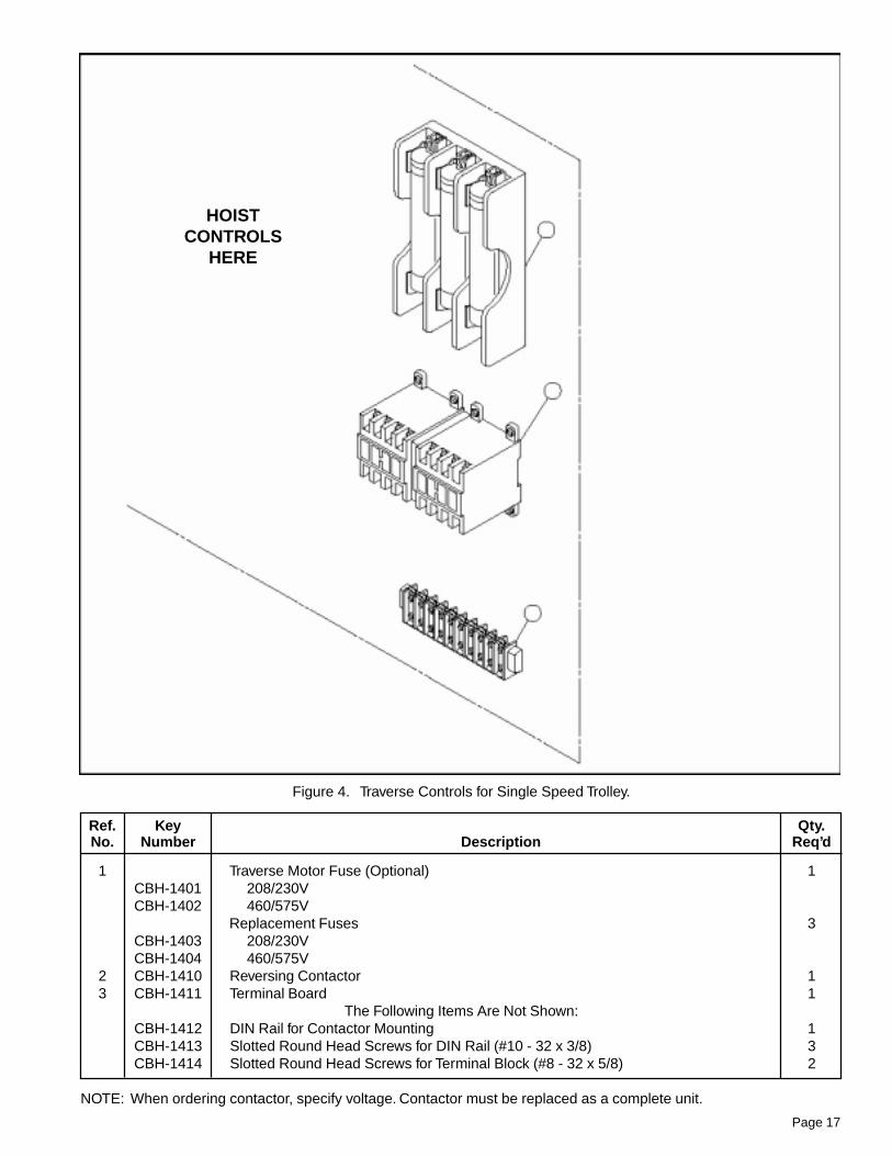
Figure 4. Traverse Controls for Single Speed Trolley.
Ref. Key Qty.No. Number Description Req’d
1 Traverse Motor Fuse (Optional) 1CBH-1401 208/230VCBH-1402 460/575V
Replacement Fuses 3CBH-1403 208/230VCBH-1404 460/575V
2 CBH-1410 Reversing Contactor 13 CBH-1411 Terminal Board 1
The Following Items Are Not Shown:CBH-1412 DIN Rail for Contactor Mounting 1CBH-1413 Slotted Round Head Screws for DIN Rail (#10 - 32 x 3/8) 3CBH-1414 Slotted Round Head Screws for Terminal Block (#8 - 32 x 5/8) 2
NOTE: When ordering contactor, specify voltage. Contactor must be replaced as a complete unit.
HOISTCONTROLS
HERE

Page 18
Ref. Part Qty.No. Number Description Req’d
1 Traverse Motor Fuse (Optional) 1CBH-1401 208/230VCBH-1402 460/575V
Replacement Fuses 3CBH-1403 208/230VCBH-1404 460/575V
2 CBH-1410 Reversing Contactor 13 CBH-1411 Terminal Board 14 CBH-1511 Time Delay Relay 15 CBH-1512 Fast Contactor 1
The Following Items Are Not Shown:CBH-1412 DIN Rail for Contactor Mounting 1CBH-1413 Slotted Round Head Screws for DIN Rail (#10 - 32 x 3/8) 3CBH-1414 Slotted Round Head Screws for Terminal Block (#8 - 32 x 5/8) 2CBH-1513 Slotted Round Head Screws for Time Delay Relay (#8 - 32 x 7/8) 2
NOTE: When ordering contactors, specify voltage. Contactors must be replaced as a complete unit.
Figure 5. Traverse Controls for Two Speed Trolley.

Page 19
NOTES

LIFT-TECH INTERNATIONALDivision of Columbus McKinnonMUSKEGON, MICHIGAN 49443
WARRANTY
Recommended Spare Partsfor Your SHAW-BOX Traverse
Certain parts of your traverse will, in time, require replacement under normal wear conditions. It issuggested that the following parts be purchased for your traverse as spares for future use.
Description Quantity
Contactor 1
Traverse Fuses (If Furnished) 3
Axle Bearings 4
NOTE: When ordering parts always furnish Catalog Number and Part Number.
Parts of your traverse are available from your local authorized SHAW-BOX repair station. For the locationof your nearest repair station, write:
In USA In CanadaLIFT-TECH INTERNATIONAL, INC. Lift-Tech InternationalPO BOX 769 Cranes & Hoist, Inc.MUSKEGON MI 49443-0769 53-D Cowansview Road
Cambridge, Ontario N1R 7L2
or phone: 616-733-0821 519-621-3201
WARRANTY AND LIMITATION OF REMEDY AND LIABILITY
A. Seller warrants that its products and parts, when shipped, andits work (including installation, construction and start-up), whenperformed, will meet applicable specifications, will be of goodquality and will be free from defects in material and workmanship.All claims for defective products or parts under this warranty mustbe made in writing immediately upon discovery and, in any event,within one (1) year from shipment of the applicable item unlessSeller specifically assumes installation, construction or start-upresponsibility. All claims for defective products or parts when Sellerspecifically assumes installation, construction or start-up responsi-bility, and all claims for defective work must be made in writingimmediately upon discovery and, in any event, within one (1) yearfrom completion of the applicable work by Seller, provided; how-ever, all claims for defective products and parts must be made inwriting no later than eighteen (18) months after shipment. Defectiveitems must be held for Seller’s inspection and returned to theoriginal f.o.b. point upon request. THE FOREGOING IS EXPRESSLYIN LIEU OF ALL OTHER WARRANTIES WHATSOEVER, EX-PRESS, IMPLIED AND STATUTORY, INCLUDING, WITHOUTLIMITATION, THE IMPLIED WARRANTIES OF MERCHANTABIL-ITY AND FITNESS.
B. Upon Buyer’s submission of a claim as provided above and itssubstantiation, Seller shall at its option either (i) repair or replace itsproduct, part or work at either the original f.o.b. point of delivery orat Seller’s authorized service station nearest Buyer or (ii) refund anequitable portion of the purchase price.
C. This warranty is contingent upon Buyer’s proper maintenanceand care of Seller’s products, and does not extend to fair wear andtear. Seller reserves the right to void warranty in event of Buyer’suse of inappropriate materials in the course of repair or mainte-nance, or if Seller’s products have been dismantled prior tosubmission to Seller for warranty inspection.
D. The foregoing is Seller’s only obligation and Buyer’s exclusiveremedy for breach of warranty, and is Buyer’s exclusive remedyhereunder by way of breach of contract, tort, strict liability orotherwise. In no event shall Buyer be entitled to or Seller liable forincidental or consequential damages. Any action for breach of thisagreement must be commenced within one (1) year after the causeof action has accrued.