Instructions 95-8502 - Biblioteket HSN · PDF fileInstructions 95-8502 Protect•ir...
21
Instructions 95-8502 Protect•ir Multispectrum IR Flame Detector X3300 Detector Electronics Corporation 6901 West 110th Street • Minneapolis, Minnesota 55438 USA Tel: 952.941.5665 or 800.765.3473 • Fax: 952.829.8750 9/00 95-8502
Transcript of Instructions 95-8502 - Biblioteket HSN · PDF fileInstructions 95-8502 Protect•ir...

Instructions 95-8502
Protect•ir Multispectrum IR Flame Detector
X3300
Detector Electronics Corporation6901 West 110th Street • Minneapolis, Minnesota 55438 USATel: 952.941.5665 or 800.765.3473 • Fax: 952.829.8750 9/00 95-8502

IMPORTANTBe sure to read and understand the entireinstruction manual before installing or operating theflame detection system.
WARNINGDo not open the detector assembly in a hazardousarea when power is applied. The detector containsno user serviceable components and should neverbe opened. Doing so could disturb critical opticalalignment and calibration parameters, possiblycausing serious damage. This type of damagecould be undetected and could result in failure tosee a fire and/or false alarm.
CAUTIONThe wiring procedures in this manual are intendedto ensure proper functioning of the device undernormal conditions. However, because of the manyvariations in wiring codes and regulations, totalcompliance to these ordinances cannot beguaranteed. Be certain that all wiring complieswith the NEC as well as all local ordinances. If indoubt, consult the authority having jurisdictionbefore wiring the system. Installation must bedone by a properly trained person.
CAUTIONTo prevent unwanted actuation or alarm,extinguishing devices must be disconnected priorto performing detection system tests ormaintenance.
ATTENTIONRemove protective cap from front of the detectorbefore activating the system.
ATTENTIONObserve precautions for handling electrostaticsensitive devices.
ATTENTIONThe X3300 includes the Automatic Optical Integrity(oi) feature — a calibrated performance test that isautomatically performed once per minute to verifycomplete detector operation capabilities. Notesting with an external test lamp is required.
DESCRIPTION
The X3300 Protect•ir is a multispectrum infrared (IR)flame detector. It provides unsurpassed detection offires from light to heavy hydrocarbon fuels combinedwith the highest degree of false alarm rejection. Thedetector is suitable for use in indoor and outdoorapplications with NEMA 4X/IP66 classifications as wellas EExd/EExe explosion-proof ratings.
The X3300 contains three IR sensors, signal processingcircuitry, and fire and fault relays. A tricolor LED on thedetector faceplate indicates normal, fire alarm, and faultconditions.
Protect•ir
Multispectrum IR Flame Detector
X3300
©Detector Electronics Corporation 2000 9/00 95-8502
DET-TRONICS®
*oi is Detector Electronics' Trademark for its patented OpticalIntegrity Systems, U.S. Patent 3,952,196, United Kingdom Patent1,534,969, Canada Patent 1,059,598.
INSTRUCTIONS

Factory configurable options include:
• Automatic or Manual Optical Integrity (oi)
• Fire and Fault Relay Operation
– Normally Open (N.O.) or Normally Closed (N.C.)Contacts
– Normally Energized or Normally De-Energized (Firerelay)
– Latching or Non-latching.
• 4 to 20 mA output.
Table 2—Factory Configuration Options (Not Changeable in the Field)
Option Available Configurations
Sensitivity • Detects 1 square foot gasoline fire at 210 feet (very highsensitivity) or 100 feet (medium sensitivity).
Optical Integrity (oi) * Automatic oi - Automatically checks internal circuitry andcleanliness of viewing windows to ensure proper operation.If a fault condition exists, the amber Fault LED lights.
• Manual oi - Cleanliness of viewing windows test can bemanually initiated by closing an external switch that is elec-trically connected between the oi lead and circuit ground.Warning: Successful Manual oi test results in fire alarmrelay activation and red Alarm LED lights.
• Internal circuitry is automatically tested independent of theManual oi test
Fire Relay Latching/Non-Latching • Latching - Relay remains in “Fire” condition after fire hasbeen detected until X3300 power is cycled.
* Non-latching - Relay remains in “Fire” condition only as longas a fire is being detected.
Normally Energized/De-Energized • Normally Energized - Fire relay is energized in non-alarm(no fire) condition.
* Normally De-Energized - Fire relay is de-energized in non-alarm (no fire) condition.
Contacts Normally Open/Closed * Normally Open - Fire relay contacts are open in non-alarm(no fire) condition.
• Normally Closed - Fire relay contacts are closed in non-alarm (no fire) condition.
Fault Relay Latching/Non-Latching • Latching - Relay remains in “Fault” condition after fault hasbeen detected until X3300 power is cycled.
* Non-latching - Relay remains in “Fault” condition only aslong as a fault is being detected.
Normally Energized * Normally Energized - Fault relay is energized with no faultpresent.
Contacts Normally Open/Closed * Normally Open - Fault relay contacts are open when fault ispresent.
• Normally Closed - Fault relay contacts are closed whenfault is present.
4 to 20 mA Output • Current output level indicates detector status condition.
* Standard Configuration2
Detector Status LED Indicator
Power On/Normal Operation Green (no fault or fire alarm)
Fault Yellow
Fire (Alarm) Red
Medium Sensitivity Two Yellow FlashesDuring Power-up
Very High Sensitivity Four Yellow FlashesDuring Power-up
Table 1—Detector Status Indicator

Refer to the “Ordering Information“ section for acomplete list of available options and accessories.
Table 1 indicates the condition of the LED for eachdetector status. The LED is non-latching. Fire and Faultrelay condition for each detector status variesaccording to the factory configuration.
FACTORY CONFIGURATION OPTIONS
The X3300 is configured at the factory to operate asspecified when ordered. Refer to the descriptions inTable 2 for a functional explanation of eachconfiguration option.
NOTEFactory configurable options cannot be changed inthe field.
4 TO 20 MA OUTPUT
This option provides a 4 to 20 mA dc current output fortransmitting detector status information to other devices.The circuit can be wired in either an isolated or non-isolated configuration and can drive a maximum loopresistance of 500 ohms from 18 to 19.9 volts dc and 600ohms from 20 to 32 volts dc. Table 3 indicates thedetector status conditions represented by the variouscurrent levels. The output is calibrated at the factory,with no need for field calibration.
NOTE
The output of the 4 to 20 mA current loop is notmonitored by the fault detection circuitry of theX3300. Therefore, an open circuit on the loop willnot cause the detector status LED to indicate afault.
GENERAL APPLICATIONINFORMATION
RESPONSE CHARACTERISTICS
Response is dependent on the type of fuel, thetemperature of the fuel, and the time required for the fireto come to equilibrium. As with all fire tests, resultsmust be interpreted according to an individualapplication.
See Appendix A for fire test results.
IMPORTANT APPLICATION CONSIDERATIONS
In applying any type of sensing device as a firedetector, it is important to know of any conditions thatcan prevent the device from responding to fire, and alsoto know what other sources besides fire can cause thedevice to respond.
Welding
Arc welding should not be performed within 40 feet ofthe long range detector (10 feet for medium rangedetector). It is recommended that the system bebypassed during welding operations in situations wherethe possibility of a false alarm cannot be tolerated. Gaswelding mandates system bypass, since the gas torchis an actual fire. Arc welding rods can contain organicbinder materials in the flux that burn during the weldingoperation and are detectable by the X3300. Weldingrods with clay binders do not burn and will not bedetected by the X3300.
Artificial Lighting
The X3300 should not be located within 3 feet ofartificial lights. Artificial lights should not be positionedso that they are pointed directly at the detector.
EMI/RFI Interference
The X3300 is resistant to interference by EMI and RFI. Itwill not respond to a 5 watt walkie-talkie at distancesgreater than 1 foot. Do not operate a walkie-talkie within1 foot of the X3300.
Non-Carbon Fires
The X3300 is a multiple spectrum IR device withdetection limited to carbonaceous fuels. It should notbe used to detect fires that do not contain carbon, suchas hydrogen, sulfur and burning metals.
3 95-8502
Current Level Detector Status
0 mA Open Circuit1 mA General Fault2 mA Oi Fault3 mA Hi Background IR4 mA Normal Operation
20 mA Alarm
Table 3—Detector Status Conditions Indicated by Current Level

INSTALLATION
DETECTOR POSITIONING
Detectors should be positioned to provide the bestunobstructed view of the area to be protected. Thefollowing factors should also be taken into consideration:
• Identify all high risk fire ignition sources.
• Be sure that enough detectors are used to adequatelycover the hazardous area.
• Locate and position the detector so that the firehazard(s) are within both the field of view anddetection range of the device. Refer to Appendix Afor specific information.
• Be sure that the unit is easily accessible for cleaningand other periodic servicing.
• For outdoor applications, the detector should beaimed downward at least 10 to 20 degrees to allowlens openings to drain. See Figure 1.
• For best performance, the detector should bemounted on a rigid surface in a low vibration area.
• Dense fog, rain or ice can absorb IR radiation andreduce the sensitivity of the detector.
• Although IR detectors are less affected by smoke thanother detectors, the X3300 should not be placedwhere rising combustion products can obscure itsvision. If smoke is expected before fire, smoke orother alternative detectors should be used inconjunction with the X3300. For indoor applications, ifdense smoke is expected to accumulate at the onsetof a fire, mount the detector on a side wall at least afew feet (approximately 1 meter) down from theceiling.
• If possible, fire tests should be conducted to verifycorrect detector positioning and coverage.
WIRING REQUIREMENTS
WIRE SIZE AND TYPE
The system should be wired using a 14 to 22 gauge (1.3to 0.5 mm2) cable. The wire size selected should bebased on the number of detectors connected, thesupply voltage and the cable length. A minimum inputvoltage of 18 vdc must be present at the X3300.
The use of shielded cable is recommended to protectagainst interference caused by EMI and RFI. Whenusing cables with shields, terminate the shields asshown in Figures 6 through 8.
In applications where the wiring cable is installed inconduit, the conduit should not be used for wiring toother electrical equipment.
CAUTIONInstallation of the detector and wiring should beperformed only by qualified personnel.
PROTECTION AGAINST MOISTURE DAMAGE
It is important to take proper precautions duringinstallation to ensure that moisture will not come incontact with the electrical connections or componentsof the system. The wiring pigtail for the X3300 is factorysealed for easy installation onto a junction box whereelectrical connections are made. The integrity of thesystem regarding moisture protection must bemaintained for proper operation and is the responsibilityof the installer.
If conduit is used, drains must be installed at watercollection points to automatically drain accumulatedmoisture. Conduit breathers should be installed atupper locations to provide ventilation and allow watervapor to escape. At least one breather should be usedwith each drain.
4
Figure 1—Detector Orientation Relative to Horizon
CENTER AXIS OF DETECTOR FIELD OF VIEW
CENTER AXIS OF DETECTOR FIELD OF VIEW
INCORRECT
CORRECT
NOTE: DETECTOR MUST ALWAYS BE AIMEDDOWNWARD AT LEAST 10 TO 20 DEGREES.
B1974

Conduit raceways should be inclined so that water willflow to low points for drainage and will not collect insideenclosures or on conduit seals. If this is not possible,install conduit drains above the seals to prevent thecollection of water or install a drain loop below thedetector with a conduit drain at the lowest point of theloop.
The detector is factory sealed. Conduit seals are notrequired for compliance with explosion-proof installationrequirements.
MOUNTING AND WIRING PROCEDURERefer to the procedure below and the listed figures tomount and wire the X3300.
Figure 1 – Detector Orientation Relative to HorizonFigure 2 – Wiring Terminal IdentificationFigure 3 – X3300 with Q9003 Swivel MountFigure 4 – Front View of the X3300Figure 5 – X3300 Terminal BlockFigure 6 – A Typical SystemFigure 7 – X3300 Detector with 4 to 20 mA Output
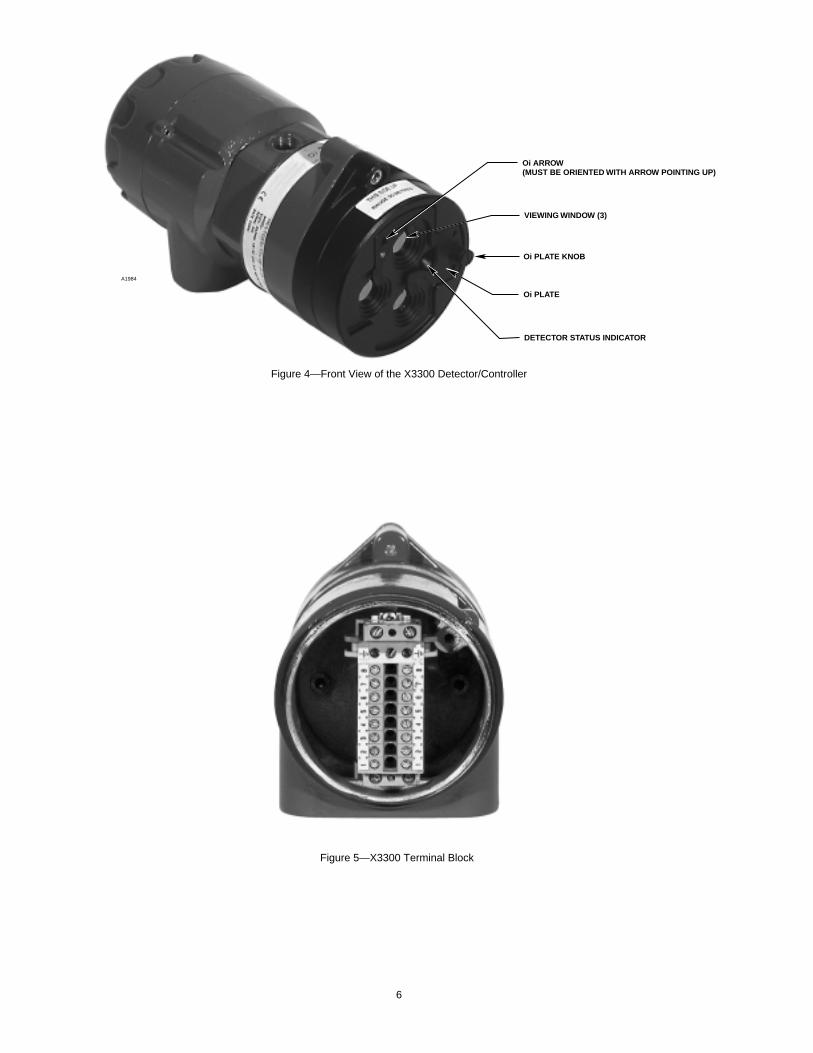
oi PLATE ORIENTATION
Refer to Figure 4 and insure that the oi plate will beoriented as shown when the X3300 is mounted andsighted. This will ensure proper operation of the oisystem and will also minimize the accumulation ofmoisture and contaminants between the oi plate andthe viewing windows. The oi plate includes an arrow,which should be pointed in the up direction, indicatingthat the oi plate and detector are correctly oriented.
IMPORTANTThe oi plate must be securely tightened to ensureproper operation of the oi system.
INSTALLATION USING Q9003 MOUNTINGBRACKET
1. Install the swivel mounting bracket assembly on thewall or ceiling. The installation surface should befree of vibration. Refer to Figure 8 for dimensions ofthe Q9003 swivel mount.
2. Make field connections following local ordinancesand guidelines in this manual. Refer to Figures 2and 6. If the detector is equipped with 4 to 20 mAoutput, refer to Figure 7.
NOTEConnect the shield to power supply minus (circuitground) at the detector end. At the fire panel end,connect the shield and power supply minus tochassis ground through a 0.47 µF 400 Volt non-polarized capacitor (not supplied).
3. Check all field wiring to be sure that the properconnections have been made.
IMPORTANTDo not test any wiring connected to the detectorwith a meg-ohmmeter. Disconnect wiring at thedetector before checking system wiring forcontinuity.
4. Make the final sighting adjustments and ensure thatthe mounting bracket hardware is tight.
5 95-8502
COLOR FUNCTION
RELAY 4 TO 20 MA
WHITE
BLACK
RED
COLOR
WHITE
BLACK
RED
GRAY
PURPLE
BROWN
BLUE
GREEN GREEN
MANUAL Oi
DC –
DC+
FUNCTION
MANUAL Oi
DC –
DC+
FAULT NO
FAULT C
FIRE NO
FIRE C
CHASSIS CHASSIS
WHT/BRN
WHT/RED
4 TO 20 (–)
4 TO 20 (+)
A1977
1
2
3
4
5
6
7
8
TERMI-NAL #
Figure 2—Wiring Terminal Identification
Figure 3—X3300 with Q9003 Mounting Bracket
6
Oi ARROW(MUST BE ORIENTED WITH ARROW POINTING UP)
VIEWING WINDOW (3)
Oi PLATE KNOB
Oi PLATE
DETECTOR STATUS INDICATOR
A1984
Figure 4—Front View of the X3300 Detector/Controller
Figure 5—X3300 Terminal Block

7 95-8502
X3300
B1978
FIRE ALARM PANEL
ALARM
24 VDC+
–
oi
–
+
FAULT RELAY 1
ALARM RELAY 2
WIRING NOTES:
1 FAULT RELAYS SHOWN HAVE BEEN SPECIFIED (WHEN ORDERED) TO HAVE NORMALLY CLOSED CONTACTS AND TO BE NORMALLY ENERGIZED WITH NO FAULT PRESENT.
2 ALARM RELAYS SHOWN HAVE BEEN SPECIFIED (WHEN ORDERED) TO HAVE NORMALLY OPEN CONTACTS AND TO BE NORMALLY DE-ENERGIZED WITH NO ALARM CONDITION PRESENT.
3 INDIVIDUAL MANUAL oi TEST SWITCHES CAN BE INSTALLED REMOTELY OR A DETECTOR SELECTOR AND ACTIVATION SWITCH CAN BE INSTALLED AT THE FIRE PANEL. TEST SWITCHES ARE NOT SUPPLIED.
4 END OF LINE DEVICE SUPPLIED BY PANEL.
END OFLINE DEVICE 4
oi TEST 3
.47 µF/400 VFILM CAPACITOR
GREEN
COLOR
RELAY 4 TO 20 MA
WHITE
BLACK
RED
GRAY
PURPLE
BROWN
BLUE
GREEN
FUNCTION
MANUAL Oi
DC –
DC+
FAULT NO
FAULT C
FIRE NO
FIRE C
CHASSIS
COLOR
WHITE
BLACK
RED
GREEN
WHT/BRN
WHT/RED
FUNCTION
MANUAL Oi
DC –
DC+
CHASSIS
4 TO 20 (–)
4 TO 20 (+)
(4)
(1)
(2)
(3)
(5)
(6)
(7)
1
2
3
4
5
6
7
8
TERMI-NAL #
Figure 6—A Typical System
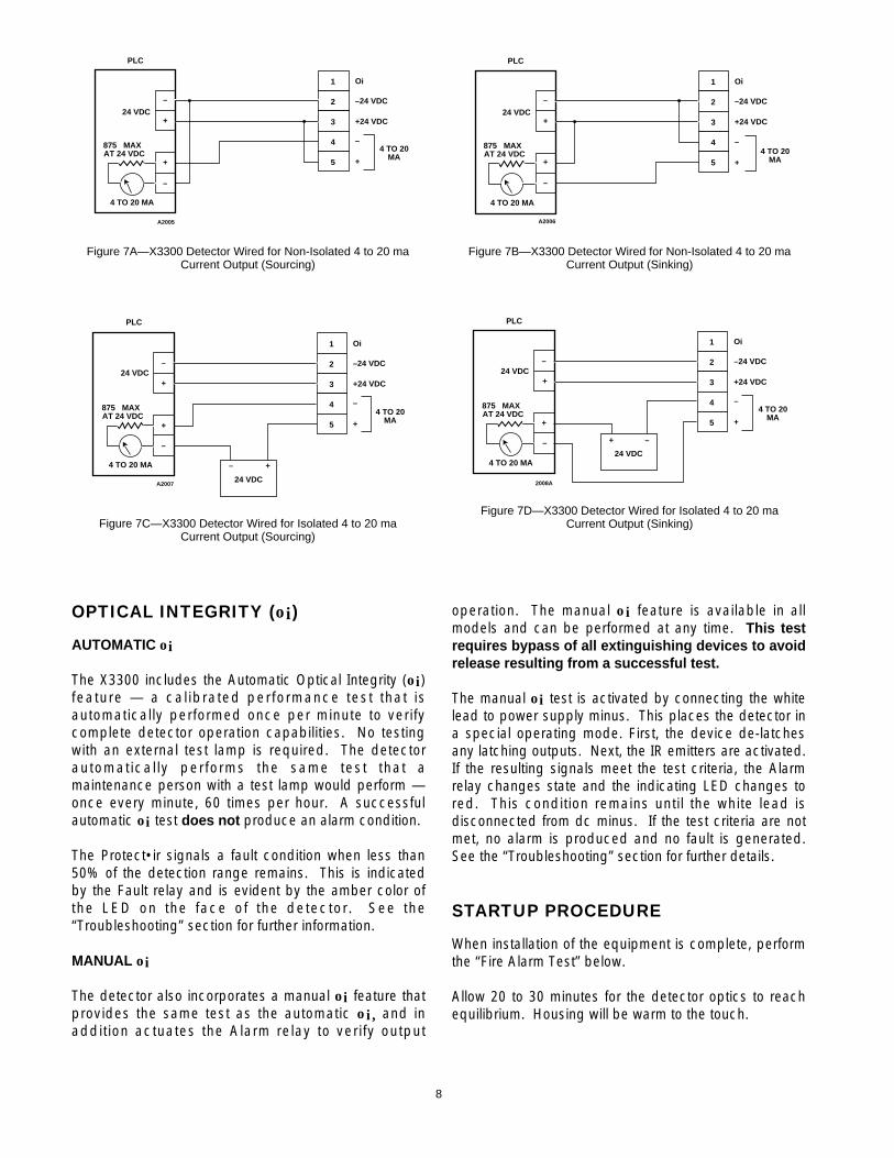
OPTICAL INTEGRITY (oi)
AUTOMATIC oi
The X3300 includes the Automatic Optical Integrity (oi)feature — a calibrated performance test that isautomatically performed once per minute to verifycomplete detector operation capabilities. No testingwith an external test lamp is required. The detectorautomatically performs the same test that amaintenance person with a test lamp would perform —once every minute, 60 times per hour. A successfulautomatic oi test does not produce an alarm condition.
The Protect•ir signals a fault condition when less than50% of the detection range remains. This is indicatedby the Fault relay and is evident by the amber color ofthe LED on the face of the detector. See the“Troubleshooting” section for further information.
MANUAL oi
The detector also incorporates a manual oi feature thatprovides the same test as the automatic oi, and inaddition actuates the Alarm relay to verify output
operation. The manual oi feature is available in allmodels and can be performed at any time. This testrequires bypass of all extinguishing devices to avoidrelease resulting from a successful test.
The manual oi test is activated by connecting the whitelead to power supply minus. This places the detector ina special operating mode. First, the device de-latchesany latching outputs. Next, the IR emitters are activated.If the resulting signals meet the test criteria, the Alarmrelay changes state and the indicating LED changes tored. This condition remains until the white lead isdisconnected from dc minus. If the test criteria are notmet, no alarm is produced and no fault is generated.See the “Troubleshooting” section for further details.
STARTUP PROCEDURE
When installation of the equipment is complete, performthe “Fire Alarm Test” below.
Allow 20 to 30 minutes for the detector optics to reachequilibrium. Housing will be warm to the touch.
8
24 VDC
4 TO 20 MA
PLC
–
+
875 MAXAT 24 VDC
–
–
4 TO 20MA
Oi
–24 VDC
+24 VDC
1
2
3
4
5 +
+
A2005
Figure 7A—X3300 Detector Wired for Non-Isolated 4 to 20 maCurrent Output (Sourcing)
24 VDC
4 TO 20 MA
PLC
–
+
875 MAXAT 24 VDC
–
–
4 TO 20MA
Oi
–24 VDC
+24 VDC
1
2
3
4
5 +
+
A2006
Figure 7B—X3300 Detector Wired for Non-Isolated 4 to 20 maCurrent Output (Sinking)
24 VDC
4 TO 20 MA
PLC
– +
24 VDC
–
+
875 MAXAT 24 VDC
–
–
4 TO 20MA
Oi
–24 VDC
+24 VDC
1
2
3
4
5 +
+
A2007
Figure 7C—X3300 Detector Wired for Isolated 4 to 20 maCurrent Output (Sourcing)
24 VDC
4 TO 20 MA
PLC
–+
24 VDC–
+
875 MAXAT 24 VDC
–
–
4 TO 20MA
Oi
–24 VDC
+24 VDC
1
2
3
4
5 +
+
2008A
Figure 7D—X3300 Detector Wired for Isolated 4 to 20 maCurrent Output (Sinking)

FIRE ALARM TEST
1. Disable any extinguishing equipment that isconnected to the system.
2. Apply input power to the system.
3. Connect the oi test line to dc minus for 5 to 10seconds or perform a pan fire test. The alarm relaywill change states and the red alarm LED willilluminate when the device goes into an alarmcondition.
4. Disengage the oi test line or extinguish the test fire.If the Alarm relay is configured for the standardnon-latching operation, it will change states and thered LED will turn off. If the unit has latching relays,they can be reset by removing input power (0.1second minimum).
5. Repeat this test for all detectors in the system. If aunit fails the test, refer to the “Troubleshooting”section.
6. Verify that all detectors in the system are properlyaimed at the area to be protected.
7. Enable extinguishing equipment when the test iscomplete.
TROUBLESHOOTING
WARNINGThe detector contains no user serviceablecomponents and should never be opened.
1. Disable any extinguishing equipment that isconnected to the unit.
2. Inspect the viewing windows for contamination andclean as necessary. The detector is relativelyinsensitive to airborne contaminants, however, thickdeposits of ice, dirt, or oil will reduce sensitivity.(Refer to the “Maintenance” section for completeinformation regarding cleaning of the detectorviewing window.)
3. Check input power to the unit.
4 If the fire system has a logging function, check thefire panel log for relay status and/or 4 to 20 mAoutput information. See Table 4.
5. Turn off the input power to the detector and checkall wiring for continuity. Important: Disconnectwiring at the detector before checking systemwiring for continuity.
9 95-8502
10.7 INCHES(27.2 CM)
7.8 INCHES(19.8 CM)
3.9 INCHES(9.9 CM)
3.9 INCHES(9.9 CM)
3.0 INCHES(7.6 CM)
3.0 INCHES(7.6 CM)
0.4 INCH DIA.(1.0 CM)
A1981
Figure 8—Q9003 Mounting Bracket Dimensions in Inches (CM)

6. If all wiring checks out and cleaning of the oiplate/window did not correct the fault condition,check for high levels of background IR radiation bycovering the detector with the factory suppliedcover or aluminum foil. If the fault condition clearswithin 6 minutes or less, extreme background IR ispresent. Re-adjust the view of the detector awayfrom the IR source or relocate the detector.
If none of these actions corrects the problem, return thedetector to the factory for repair.
NOTESince the entire unit must be returned to thefactory for repair, it is highly recommended that acomplete spare be kept on hand for f ieldreplacement to ensure continuous protection.
PERIODIC CHECKOUT PROCEDURE
Periodic testing is not required when the detector isconfigured for automatic optical integrity testing. If theX3300 is configured for manual oi operation, acheckout of the system using the oi feature should beperformed on a regularly scheduled basis to ensure thatthe system is operating properly. To test the system,perform the “Fire Alarm Test” as described in the“Startup Procedure” section of this manual.
MAINTENANCE
IMPORTANTPeriodic flamepath inspections are notrecommended since the product is not intended tobe serviced and provides proper ingress protectionto eliminate potential deterioration of the flamepaths.
WARNINGThe detector contains no user serviceablecomponents and should never be opened.
To maintain maximum sensitivity, the viewing windowsof the X3300 must be kept relatively clean. Refer to theprocedure below for instructions.
CLEANING PROCEDURE
CAUTIONDisable any extinguishing equipment that isconnected to the unit to prevent unwantedactuation.
To clean the window and oi plate, use Det-Tronicswindow cleaner (part number 001680-001) and a softcloth or tissue and refer to the procedure below.
1. Disable any extinguishing equipment that isconnected to the unit.
2. Since the X3300 is less affected by contaminationthan other detectors, removal of the oi plate isneeded only under extreme conditions. In addition,it is not necessary to achieve perfect cleanliness,because IR is not significantly absorbed by slightfilms of oil and/or salt. If a fault condition is stillindicated after cleaning, remove and clean the oiplate using the procedure below.
3. Clean all three viewing windows and reflectorsurfaces thoroughly using a clean cloth, cottonswab or tissue and Det-Tronics window cleaningsolution. If a stronger solution is needed, isopropylalcohol may be used.
Oi PLATE REMOVAL
1. Remove the oi plate from the detector by looseningthe oi plate knob.
2. Thoroughly clean the oi plate reflective surfaces,holding it by its edges to avoid leaving fingerprintson the inside reflective surface.
3. Re-install the oi plate. Ensure that the plate is flaton the detector surface. Tighten the oi plate knobsecurely (40 oz/inches).
NOTEIf the oi plate is removed, be sure to install theoriginal oi plate. oi plates are not interchangeableand should not be mixed with oi plates from otherdetectors.
NOTEIf corrosive contaminants in the atmosphere causethe oi plate surface to deteriorate to the extent thatit is no longer possible to restore it to its originalcondition, it must be replaced. Consult factory foroi plate replacement procedure.
10
Current Level Status Action
0 mA Open Circuit Check wiring connections.
1 mA General Fault Cycle power.
2 mA Oi Fault Clean windows.
3 mA Hi Background IR Remove IR source oraim detector away from IR source.
4 mA Normal Operation
20 mA Alarm
Table 4—Troubleshooting Guide

FEATURES
• Long detection range to carbonaceous fires.
• Maximum false alarm rejection capability.
• Maintains the capability to respond to a fire in thepresence of modulated blackbody radiation withoutfalse alarm.
• Heated optics for increased resistance to moistureand ice.
• Factory sealed device eliminates need for explosion-proof conduit seal.
• One-hand oi plate removal for easy maintenance evenin the most difficult locations.
• Automatic and manual optical integrity (oi) testing.
• Fire and fault relays standard.
• Tricolor LED indicates normal operation, fire and faultconditions.
• Factory available fire and fault relay operation:latching/non-latching, energized/de-energized (firerelay only), normally open/normally closed.
• 4 to 20 mA isolated output.
• Other mounting options include mounting directly ontomost junction boxes using a simple adapter, or theuse of a swivel union or swivel mount available fromDet-Tronics.
• Operates under adverse weather conditions and indirty environments.
• Flame-proof/increased safety detector housing.Meets CENELEC and DNV certification requirements.
• Class A wiring per NFPA-72.
• Meets NFPA-33 response requirement for under 0.5second (available when option selected).
• 5 year warranty.
SPECIFICATIONS
OPERATING VOLTAGE— 24 volts dc nominal (18 vdc minimum, 32 vdcmaximum).
POWER CONSUMPTION—9.0 watts maximum.
POWER UP TIME—Fault indication clears after 0.5 second; device is readyto indicate an alarm condition after 30 seconds.
OUTPUT RELAYS—Fire Alarm relay, Form C, 5 amperes at 30 vdc:
The Fire Alarm relay is factory configurable fornormally open or normally closed contacts, normallyenergized or normally de-energized operation, andlatching or non-latching operation.
Fault relay, Form C, 5 amperes at 30 vdc: The Fault relay is factory configurable for normallyopen or normally closed contacts, normallyenergized or normally de-energized operation, andlatching or non-latching operation.
CURRENT OUTPUT (Not available with relays)—4 to 20 milliampere dc current, with a maximum loopresistance of 500 ohms from 18 to 19.9 volts dc and 600ohms from 20 to 32 volts dc.
TEMPERATURE RANGE—Operating: –40°F to +158°F (–40°C to +70°C).Storage: –67°F to +185°F (–55°C to +85°C).
HUMIDITY RANGE—0 to 95% relative humidity, can withstand 100%condensing humidity for short periods of time.
CONE OF VISION—The detector has a 90° cone of vision (horizontal) withthe highest sensitivity lying along the central axis.Unlike conventional detectors, the X3300 provides fullcoverage at a minimum of 70% of the maximumdetection distance.Perfect cone of vision for methane fire detection — 100feet on and off axis. See Figures 9A to 9K.
RESPONSE TIME—Can respond to fires in under 0.5 second at reduceddistances (50 feet). Response times at maximumdistance are typically under 10 seconds.
ENCLOSURE MATERIAL—Aluminum (red-painted) or 316 stainless steel.
DIMENSIONS—See Figure 10.
WIRING—14 AWG (1.5 mm2) to 22 AWG (0.3 mm2) shieldedcable is recommended.Important: 18 vdc minimum must be available at thedetector.
MOUNTING THREADS—Two sizes available: 3/4 inch NPT or M25.
11 95-8502

SHIPPING WEIGHT (Approximate)—Aluminum: 2.4 pounds (1.1 kilograms).Stainless Steel: 4.8 pounds (2.2 kilograms).
CERTIFICATION—
CENELEC: EEx d e IIC T6(Tamb = –40°C to +60°C).EEx d e IIC T5(Tamb = –40°C to +70°C).IP66.
DNV: Compliance to DNV Certification Notes No. 2.4.
CE: Conforms to all relevant European norms.
NOTEOperational performance verified from -40°C to+70°C.
WARRANTY PERIOD—5 years, sensor and electronics.
12
4.08 (103.6)
3.23 (82.04)
3.23 (82.04)
7.4 (188)
A1982
Figure 10—X3300 Dimensions in Inches (mm)
0°
15°
45°
15°
30°
30°
DETECTOR VERTICAL FIELD OF VIEWWITH DETECTOR AT 45° FROM HORIZONTAL.
0°15°15°
30°
45°
30°
45°150 ft
150 ft
120 ft
120 ft
90 ft
90 ft
60 ft
60 ft
30 ft
210 ft
210 ft
180 ft
180 ft
Figure 9A—Field of View at Indicated Distance in Feet for Gasolineat Very High Sensitivity
0°15°
30°
45°
15°30°
45°
100 ft90 ft
90 ft
80 ft
80 ft
50 ft
50 ft
40 ft
40 ft
30 ft20 ft10 ft
0°
15°
45°
15°
30°
30°
DETECTOR VERTICAL FIELD OF VIEWWITH DETECTOR AT 45° FROM HORIZONTAL.
70 ft
70 ft
60 ft
60 ft
100 ft
30 ft20 ft10 ft
Figure 9B—Field of View at Indicated Distance in Feet for Methaneat Very High Sensitivity

13 95-8502
15°30°
45°
15°30°
45°
150 ft135 ft120 ft
75 ft60 ft45 ft30 ft15 ft
105 ft90 ft
Figure 9C—Field of View at Indicated Distance in Feet forMethanol at Very High Sensitivity
0°15°15°
30°
45°
30°
45°150 ft
120 ft
90 ft
60 ft
30 ft
210 ft
180 ft
Figure 9E—Field of View at Indicated Distance in Feet for JP-5 at Very High Sensitivity
15°30°
45°
15°30°
45°
150 ft135 ft120 ft
75 ft60 ft45 ft30 ft15 ft
105 ft90 ft
Figure 9D—Field of View at Indicated Distance in Feet for Diesel at Very High Sensitivity
0°15°
30°
45°
15°30°
45°
100 ft90 ft80 ft
50 ft40 ft30 ft20 ft10 ft
70 ft60 ft
Figure 9F—Field of View at Indicated Distance in Feet for Gasolineat Medium Sensitivity
0°15°15°
30°
45°
30°
45°50 ft
40 ft
30 ft
20 ft
10 ft
70 ft
60 ft
Figure 9J—Field of View at Indicated Distance in Feet for Diesel at Medium Sensitivity
0°15°15°
30°
45°
30°
45°50 ft
40 ft
30 ft
20 ft
10 ft
65 ft60 ft
Figure 9G—Field of View at Indicated Distance in Feet for Methaneat Medium Sensitivity
0°15°15°
30°
45°
30°
45°50 ft
40 ft
30 ft
20 ft
10 ft
70 ft
60 ft
Figure 9H—Field of View at Indicated Distance in Feet forMethanol at Medium Sensitivity
0°15°
30°
45°
15°30°
45°
100 ft90 ft80 ft
50 ft40 ft30 ft20 ft10 ft
70 ft60 ft
Figure 9K—Field of View at Indicated Distance in Feet for JP-5 at Medium Sensitivity

REPLACEMENT PARTS
The detector is not designed to be repaired in the field.If a problem should develop, refer to theTroubleshooting section. If it is determined that theproblem is caused by an electronic defect, the devicemust be returned to the factory for repair.
DEVICE REPAIR AND RETURN
Prior to returning devices, contact the nearest localDetector Electronics office so that a Service Ordernumber can be assigned. A written statementdescribing the malfunction must accompany thereturned device or component to expedite finding thecause of the failure.
Pack the unit properly. Use sufficient packing materialin addition to an antistatic bag or aluminum-backedcardboard as protection from electrostatic discharge.
Return all equipment transportation prepaid to thefactory in Minneapolis.
NOTESince the entire unit must be returned to thefactory for repair, it is highly recommended that acomplete spare be kept on hand for f ieldreplacement to ensure continuous protection.
ORDERING INFORMATION
When ordering, refer to Table 5, Ordering FactoryConfiguration. For further information on the function ofeach configuration option, refer to Table 2.
ACCESSORIES
Q9003 Swivel Mount Assembly is recommended formounting the detector when using flexible electricalconduit.
REPLACEMENT PARTS
Part Number Description001680-001 Window cleaner squeeze bottle
(package of six bottles)006918-001 oi plate107427-049 O-ring 400525-006 Bolts (2)005143-001 Silicone-free grease
For assistance in ordering a system to f i t yourapplication, please contact:
Detector Electronics Corporation6901 West 110th StreetMinneapolis, Minnesota 55438 USAOperator: (952) 941-5665 or (800) 765-FIRECustomer Service: (952) 946-6491Fax: (952) 829-8750Web site: www.detronics.comE-mail: [email protected]
14
Table 5—Ordering Factory Configuration Options
Option Available Configurations
Optical Integrity (oi) * Automatic oi/manual oi• Manual oi (only)
Fire Relay • Latching
* Non-latching
• Normally Energized
* Normally De-Energized
* Normally Open
• Normally Closed
Fault Relay • Latching
* Non-latching
* Normally Energized
* Normally Open
• Normally Closed
4 to 20 mA Output • With Fire and Fault Relay
* Standard Configuration

15 95-8502
APPENDIX A
Response Characteristics of the X3300
RESPONSE CHARACTERISTICS:
Fuel Size Distance Average Response Time (feet) (seconds)
Gasoline 1 x 1 foot 100 6.0
Gasoline 1 x 1 foot 50 3.8
Diesel** 1 x 1 foot 70 7.4
Methanol 1 x 1 foot 70 9.7
Methane 30 inch plume 65 2.4
Methane 30 inch plume 55 0.8
JP-5** 2 x 2 foot 100 5.7
** 10 second pre-burn from ignition.
Medium Sensitivity
Fuel Size Distance Average Response Time (feet) (seconds)
Gasoline 1 x 1 foot 210* 8.4
Gasoline 1 x 1 foot 100 1.4
Diesel** 1 x 1 foot 150* 9.6
Methanol 1 x 1 foot 150* 5.7
Methane 30 inch plume 100 2.5
JP-5** 2 x 2 foot 210* 8.5
JP-5** 2 x 2 foot 100 2.6
Office 18” x 16” x 10” 100 4.5Paper 0.5 lb.
Corrugated 18” x 36” 100 15.8Panel
* Outdoor test condition.** 10 second pre-burn from ignition.
Very High Sensitivity
16
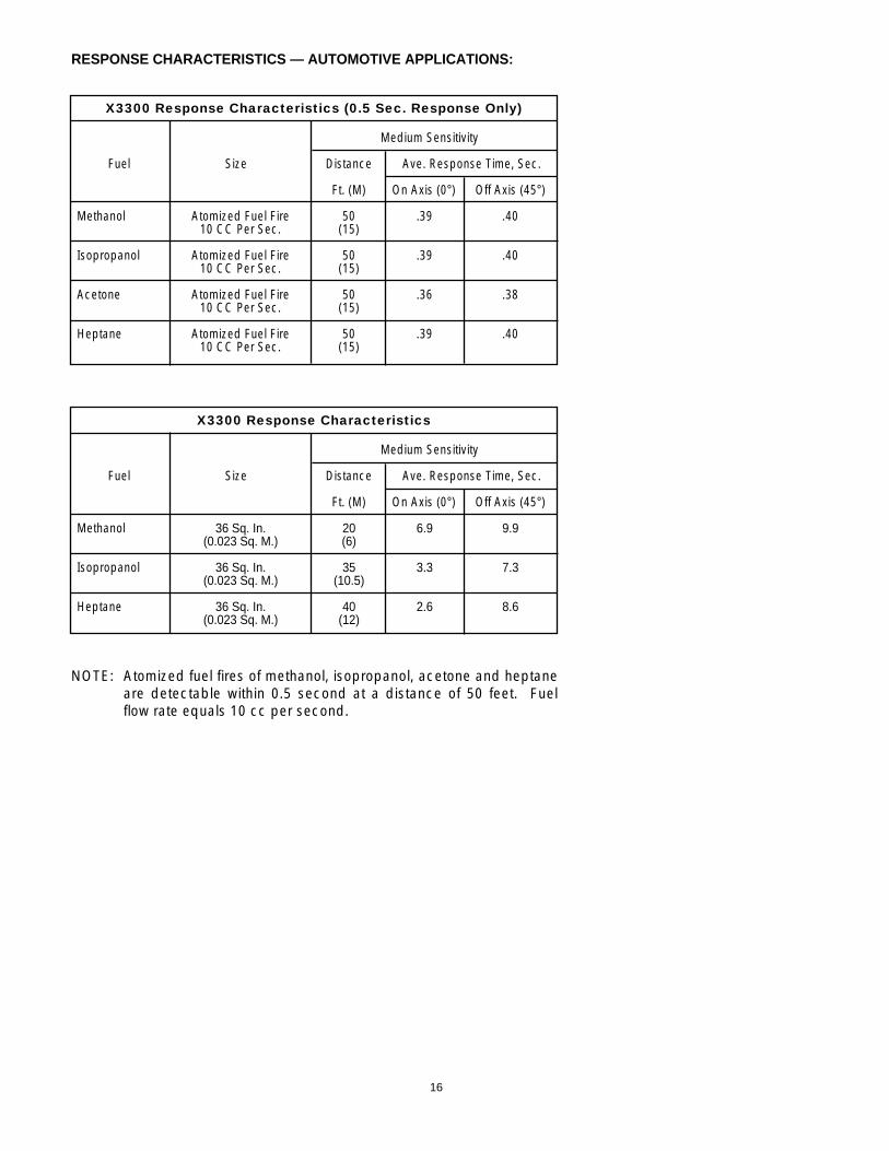
X3300 Response Characteristics (0.5 Sec. Response Only)
Medium Sensitivity
Fuel Size Distance Ave. Response Time, Sec.
Ft. (M) On Axis (0°) Off Axis (45°)
Methanol Atomized Fuel Fire 50 .39 .4010 CC Per Sec. (15)
Isopropanol Atomized Fuel Fire 50 .39 .4010 CC Per Sec. (15)
Acetone Atomized Fuel Fire 50 .36 .3810 CC Per Sec. (15)
Heptane Atomized Fuel Fire 50 .39 .4010 CC Per Sec. (15)
RESPONSE CHARACTERISTICS — AUTOMOTIVE APPLICATIONS:
X3300 Response Characteristics
Medium Sensitivity
Fuel Size Distance Ave. Response Time, Sec.
Ft. (M) On Axis (0°) Off Axis (45°)
Methanol 36 Sq. In. 20 6.9 9.9(0.023 Sq. M.) (6)
Isopropanol 36 Sq. In. 35 3.3 7.3(0.023 Sq. M.) (10.5)
Heptane 36 Sq. In. 40 2.6 8.6(0.023 Sq. M.) (12)
NOTE: Atomized fuel fires of methanol, isopropanol, acetone and heptaneare detectable within 0.5 second at a distance of 50 feet. Fuelflow rate equals 10 cc per second.

OPTICAL FAULT:The detector generated an optical fault in the presence of contamination on any single or combination of lenssurfaces verifying that the detector performs an optical integrity (oi) test for each sensor. Upon removal of thecontaminant the detector fault was cleared and the detector was verified to detect a fire.
RESPONSE CHARACTERISTICS IN THE PRESENCE OF FALSE ALARM SOURCES:
17 95-8502
False Alarm Source Distance Fire Source Distance Average Response Time (feet) (feet) (seconds)
Sunlight, direct, modulated, reflected — 6-inch propane 6 < 4
Vibration N/A 6-inch propane 6 < 10
Radio frequency interference 1 6-inch propane 12 < 1
Arc welding 40 1 x 1 foot gasoline 40 3.1
6 kw heater, modulated 100 1 x 1 foot gasoline 100 1.9
6 kw heater, modulated 10 1 x 1 foot gasoline 100 5.3
250 w vapor lamp, modulated 3 1 x 1 foot gasoline 100 2.7
300 w incandescent lamp, modulated 3 1 x 1 foot gasoline 100 3.6
500 w unshielded quartz halogen lamp, modulated 8 1 x 1 foot gasoline 100 2.7
1500 w electric radiant heater, modulated 10 1 x 1 foot gasoline 100 4.2
Two 34 w florescent lamps, modulated 3 1 x 1 foot gasoline 100 1.7
Very High Sensitivity
False Alarm Source Distance Fire Source Distance Average Response Time (feet) (feet) (seconds)
Sunlight, direct, modulated, reflected — 6-inch propane 6 < 4
Vibration* N/A 6-inch propane 6 < 10
Radio frequency interference 1 6-inch propane 6 < 1
Arc welding 10 1 x 1 foot gasoline 10 0.2
6 kw heater, modulated 100 1 x 1 foot gasoline 100 5.0
6 kw heater, modulated 10 1 x 1 foot gasoline 100 10.7
250 w vapor lamp, modulated 3 1 x 1 foot gasoline 100 7.1
300 w incandescent lamp, modulated 3 1 x 1 foot gasoline 100 9.6
500 w unshielded quartz halogen lamp, modulated 8 1 x 1 foot gasoline 100 6.3
1500 w electric radiant heater, modulated 10 1 x 1 foot gasoline 90 6.4
Two 34 w florescent lamps, modulated 3 1 x 1 foot gasoline 100 4.6
Medium Sensitivity
* Fire was verified with very high sensitivity only.

18
FALSE ALARM IMMUNITY:
False Alarm Source Distance Modulated Response Un-modulated Response(feet)
Sunlight, direct, modulated, reflected — No alarm No alarm
Vibration N/A No alarm N/A
Radio frequency interference 1 No alarm (keyed) No alarm (steady)
Arc welding 40 No alarm No alarm
6 kw heater, modulated 3 No alarm No alarm
250 w vapor lamp, modulated 3 No alarm No alarm
300 w incandescent lamp, modulated 3 No alarm No alarm
500 w unshielded quartz halogen lamp, modulated 8 No alarm No alarm
1500 w electric radiant heater, modulated 3 No alarm No alarm
Two 34 w florescent lamps, modulated 3 No alarm No alarm
Very High Sensitivity
False Alarm Source Distance Modulated Response Un-modulated Response(feet)
Sunlight, direct, modulated, reflected — No alarm No alarm
Vibration N/A No alarm N/A
Radio frequency interference 1 No alarm (keyed) No alarm (steady)
Arc welding 10 No alarm No alarm
6 kw heater, modulated 3 No alarm No alarm
250 w vapor lamp, modulated 3 No alarm No alarm
300 w incandescent lamp, modulated 3 No alarm No alarm
500 w unshielded quartz halogen lamp, modulated 8 No alarm No alarm
1500 w electric radiant heater, modulated 3 No alarm No alarm
Two 34 w florescent lamps, modulated 3 No alarm No alarm
Medium Sensitivity

19 95-8502
FIELD OF VIEW:
Fuel Size Distance Horizontal Avg. Horiz. Response Time Vertical Avg. Vert. Response Time(feet) (degrees) (seconds) (degrees) (seconds)
Gasoline 1 x 1 foot 150 +45 11.9 +45 8.5–45 9.5 –30 6.0
Gasoline 1 x 1 foot 100 +45 3.5 +45 4.2–45 4.0 –30 3.2
Diesel** 1 x 1 foot 100 +45 2.2 +45 2.1–45 4.4 –30 2.8
Methanol 1 x 1 foot 110 +45 8.5 +45 9.5–45 9.2 –30 4.3
Methane 30 inch plume 100 +45 1.9 +45 3.5–45 4.3 –30 2.0
JP-5** 2 x 2 feet 180* +45 13.3 +45 10.4–45 17.3 –30 5.0
JP-5** 2 x 2 feet 90 +45 2.9 +45 1.4–45 4.1 –30 2.5
Office 18” x 16” x 10” 80 +45 6.4 +45 8.2Paper 0.5 lb. –45 9.8 –30 6.0
Corrugated 18” x 36” 80 +45 15.6 +45 14.7Panel –45 12.2 –30 10.6
Very High Sensitivity
Fuel Size Distance Horizontal Avg. Horiz. Response Time Vertical Avg. Vert. Response Time(feet) (degrees) (seconds) (degrees) (seconds)
Gasoline 1 x 1 foot 75 +45 9.5 +45 6.4–45 9.5 –30 5.4
Gasoline 1 x 1 foot 50 +45 3.8 +45 4.1–45 3.8 –30 3.1
Diesel** 1 x 1 foot 60 +45 4.5 +45 5.5–45 6.8 –30 2.1
Methanol 1 x 1 foot 45 +45 9.0 +45 9.8–45 9.7 –30 6.6
Methane 30 inch plume 45 +45 4.4 +45 2.0–45 0.9 –30 0.5
Methane 30 inch plume 40 +45 1.7 +45 3.4–45 0.4 –30 1.4
JP-5** 2 x 2 feet 90 +45 2.9 +45 3.4–45 8.1 –30 2.5
Medium Sensitivity
* Outdoor test condition.** 10 second flame pre-burn from ignition.
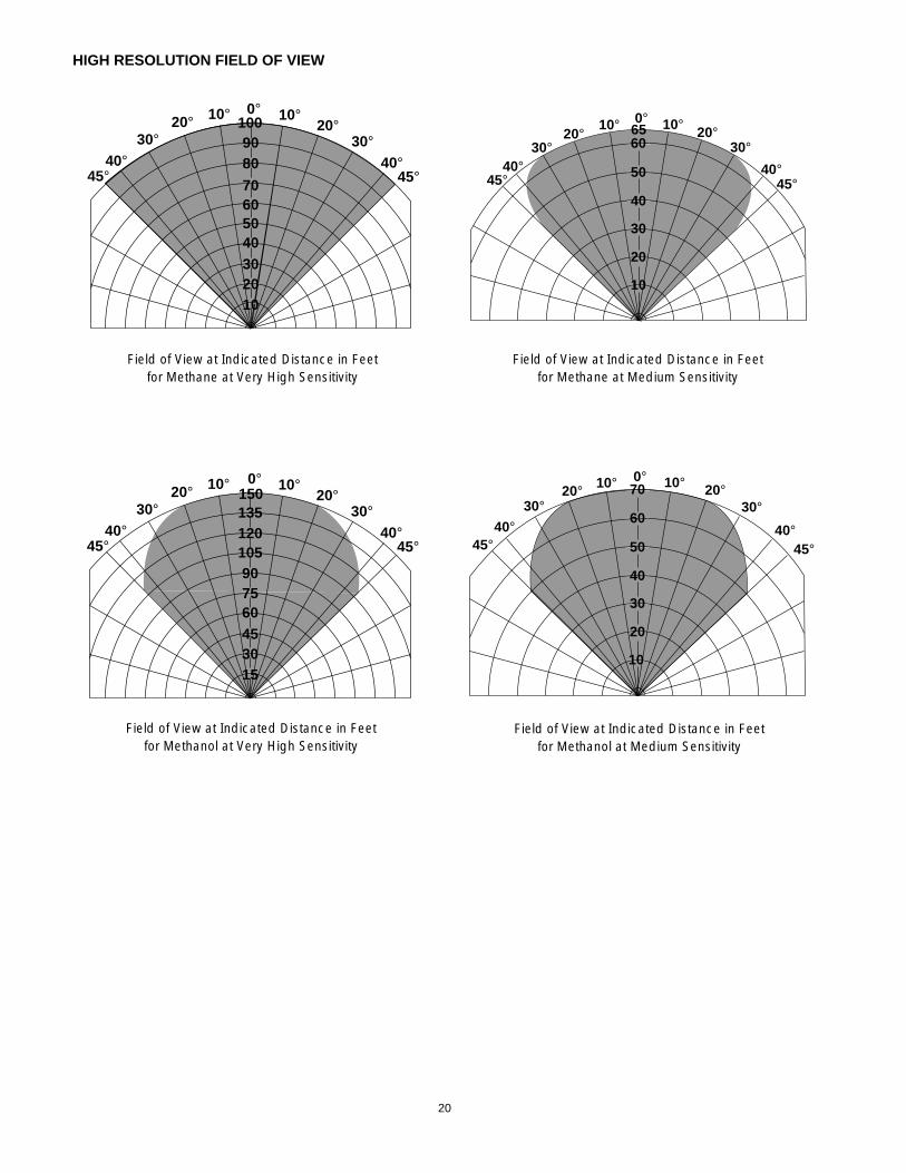
HIGH RESOLUTION FIELD OF VIEW
20
0°20°20°
30°
45°
30°
45°
1009080
5040302010
7060
40°40°
10° 10°
Field of View at Indicated Distance in Feetfor Methane at Very High Sensitivity
0°20°20°
30°
45°
30°
45°50
40
30
20
10
70
6040°40°
10° 10°
Field of View at Indicated Distance in Feetfor Methanol at Medium Sensitivity
0°20°20°
30°
45°
30°
45°
150135120
7560453015
10590
40°40°
10° 10°
Field of View at Indicated Distance in Feetfor Methanol at Very High Sensitivity
0°20°20°
30°
45°
30°
45°50
40
30
20
10
6560
40°40°
10° 10°
Field of View at Indicated Distance in Feetfor Methane at Medium Sensitivity