Instruction Sheet Learning Guide-36
177
Ethiopian TVET-System BASIC ELECTRICAL/ELECTRONIC EQUIPMENT SERVICING Level I Based on May 2011 Occupational standards October, 2019
Transcript of Instruction Sheet Learning Guide-36

Ethiopian TVET-System
BASIC ELECTRICALELECTRONIC
EQUIPMENT SERVICING Level I
Based on May 2011 Occupational standards
October 2019
EEL BEE1
Version01
Page No2 Copyright Ethiopia Federal TVET Agency
Module Title TESTING ELECTRICALampELECTRONIC PARTS
TTLM Code EEL BEE1TTLM 0919 v1
This module includes the following Learning Guides
LG36 Plan and prepare to identifytest electricalelectronic part
LG Code EEL BEE1 M10 LO1LG-36
LG37-Identifying and testing Electricalelectronic parts
LG Code EEL BEE1 M10 LO2LG-37
LG38- Test the construction of electrical electronic circuits
LG Code EEL BEE1 M10 LO3LG-38
EEL BEE1
Version01
Page No3 Copyright Ethiopia Federal TVET Agency
Instruction Sheet LG36 Plan and prepare to identifytest electrical electronic part
This learning guide is developed to provide you the necessary information regarding the
following content coverage and topics
Checking materials according to specifications and tasks
Selecting appropriate tools and test instrument according to task
requirements
Planning task to ensure occupational health and safety (OHS) guidelines
and following procedures
Identifying and preparing Electricalelectronic parts
Testing and de-solderingsoldering of electronic parts
This guide will also assist you to attain the learning outcome stated in the cover page
Specifically upon completion of this Learning Guide you will be able to-
Check materials according to specifications and tasks
Select appropriate tools and test instrument according to task requirements
Plan task to ensure occupational health and safety (OHS) guidelines and
following procedures
Identify and prepare Electricalelectronic parts correctly for testing de-
solderingsoldering of electronic parts in accordance with instructions and work
procedures
Learning Instructions
1 Read the specific objectives of this Learning Guide
2 Follow the instructions described below 3 to 6
3 Read the information written in the information ldquoSheet 1 Sheet 2 Sheet 3 and Sheet
4sheet 5rdquo in page 3 13 20 23nd 30 respectively
4 Accomplish the ldquoSelf-check 1 Self-check 2 Self-check 3 and Self-check 4rdquo rdquoin page
12 19 2224 and 33 respectively
EEL BEE1
Version01
Page No4 Copyright Ethiopia Federal TVET Agency
5 If you earned a satisfactory evaluation from the ldquoSelf-checkrdquo proceed to ldquoOperation
Sheet 1 Operation Sheet 2 and Operation Sheet 3 rdquoin page ---
6 Do the ldquoLAP testrdquo in page ndash --
11 Concept of Specification (spec)
Exact statement of the particular needs to be satisfied or essential characteristics that a
customer requires (in a good material method process service system or work) and
which a vendor must deliver Specifications are written usually in a manner that enables
both parties (andor an independent certifier) to measure the degree of conformance
They are however not the same as control limits (which allow fluctuations within a
range) and conformance to them does not necessarily mean quality (which is a
predictable degree of dependability and uniformity)
12 Types of specification
Specifications are divided generally into two main categories
(1) Performance specifications conform to known customer requirements such as
keeping a rooms temperature within a specified range
(2) Technical specifications express the level of performance of the individual units and
are subdivided into (a) individual unit specifications which state boundaries
(parameters) of the units performance consisting of a nominal (desired or mandated)
value and tolerance (allowable departure from the nominal value (b) acceptable quality
level which states limits that are to be satisfied by most of the units but a certain
percentage of the units is allowed to exceed those limits and (c) distribution
specifications which define an acceptable statistical distribution (in terms of mean
deviation and standard Deviation) for each unit and are used by a producer to monitor
its production processes
13 Importance of specification
When completing a job for someone else you should always try and follow every
specification so you can get future work from them
You may have to make sure that you follow every specification when you are trying to
set up a new factory
Information Sheet-1 Checking materials according to specifications and tasks
EEL BEE1
Version01
Page No5 Copyright Ethiopia Federal TVET Agency
It is not only sufficient to plan the required materials tools and equipments for the
lesson it needs to check and identify which of them are defect free (normal) to be
maintaining easily and not to be maintained In addition to the above consumable
components it is intended that the following consumable materials tools and testing
instruments which are going to be used in this UC are listed in the table below The
details list of these materials tools and instruments (with their specification quantities
items to traineersquos ratio) are present in Annex ldquoResource Requirementrdquo in the
corresponding curriculum Hence based on both these information the trainer can
prepare consumable materials tools and equipment request detail plan before the
practical training time
Page 6 of 177
Federal TVET Agency
AuthorCopyright
TVET program title Basic ElectricalElectronic Equipment Servicing L -1
Version -1 October 2019
Table 1 examples of some materials with their specification and tasks
Materials Specification Tasks Picture image of materials
Soldering lead We provide soldering
wire of grade
6337snpb6238604
05050 and 4060
08mm 1mm
-used to attach a wire to the pin of
a component on the rear of PCB
Flux Rosin used as flux for soldering A flux pen used for electronics rework Multicore solder containing flux Wire freshly coated with solder still immersed in molten rosin Flux
-is a chemical cleaning agent flowing agent or purifying agent Fluxes may have more than one function at a time
Page 7 of 177
Federal TVET Agency
AuthorCopyright
TVET program title Basic ElectricalElectronic Equipment Servicing L -1
Version -1 October 2019
Cables 3x25mm2
3x4mm2
-an assembly one or more wires
which may be insulated used for
transmission electrical power or
signal
Printed circuit
board (PCB)
PCB materials Conductive ink Laminate materials BT-Epoxy Composite epoxy material CEM-15 Cyanate Ester FR-2 FR-4 the most common PCB material Polyimide PTFE Polytetrafluoroethylene (Teflon)
A printed circuit board ( PCB ) mechanically supports and electrically connects electronic components or electrical components using conductive tracks pads and other features Etched from one or more sheet layers of copper laminated onto andor between sheet layers of a non-conductive substrate Components are generally soldered onto the PCB to both electrically connect and mechanically fasten them to it
Page 8 of 177
Federal TVET Agency
AuthorCopyright
TVET program title Basic ElectricalElectronic Equipment Servicing L -1
Version -1 October 2019
ElectricalElectr
onic parts and
components
(resistor diode
transistor
capacitor etc)
1kohm 10w
Wires 1mm215mm2 and
25mm2
-Used for transmission of
electricity or electrical
signals
ACDC power
supply
Total Max Power 250 W Total Max Current 208 A Input Voltage 90 V to 264 V Output Voltage 12 V to 528 V Outputs Single Size (L x W x H) 4000 x 2000 x 1290 Warranty 3 years Operating
A power supply is an electrical device that supplies electric power to an electrical load The primary function of a power supply is to convert electric current from a source to the correct voltage current and frequency to power the load As a result power supplies are sometimes referred to
as electric power converters
Page 9 of 177
Federal TVET Agency
AuthorCopyright
TVET program title Basic ElectricalElectronic Equipment Servicing L -1
Version -1 October 2019
Temperature -20 to 70 degC
Data book ECG book -is a document that summarizes the performance and other characteristics of a product machine component (eg an electronic component ) material a subsystem (eg a power supply ) or software in sufficient detail that allows a buyer to understand what the product and a design engineer to understand the role of the component in the overall system
Soldering iron Specifications Max Temp 460degc Min Temp Room Terperature Temperature Control No Voltage 230V Watts 20-50W Colour Hot Rod Red Bit type out-of-box Chisel 50W Rated Plug Round Indian Type
-It supplies heat to melt solder so that it can flow into the joint between two workpieces A soldering iron is composed of a heated metal tip and an insulated handle Heating is often achieved electrically by passing an electric current (supplied through an electrical cord or battery cables) through a resistive heating element
Page 10 of 177
Federal TVET Agency
AuthorCopyright
TVET program title Basic ElectricalElectronic Equipment Servicing L -1
Version -1 October 2019
Soldering Sucker
Length 19cm
Diameter 2cm
Solders can be removed using a vacuum plunger (on the right) and a soldering iron In electronics desoldering is the removal of solder and components from a circuit board for troubleshooting repair replacement and salvage
Page 11 of 177
Federal TVET Agency
AuthorCopyright
TVET program title Basic ElectricalElectronic Equipment Servicing L -1
Version -1 October 2019
Directions Answer all the questions listed below
I Match column ldquoArdquo with column ldquoBrdquo
ldquoArdquo
________1 Specifications
ldquo Brdquo
A It supplies heat to melt solder so that it can flow into the joint between two workpieces
________2 Soldering Sucker
B Express the level of performance of the individual units
________3 Data book C Removes solders using a vacuum plunger
________4 Flux D is a chemical cleaning agent flowing agent or purifying agent
________5 Soldering iron
E Is a document that summarizes the performance and other characteristics of a
product machine component
Self-Check -1
Written Test
Note Satisfactory rating - 3 points Unsatisfactory - below 3 points
You can ask you teacher for the copy of the correct answers
Page 12 of 177
Federal TVET Agency
AuthorCopyright
TVET program title Basic ElectricalElectronic Equipment Servicing L -1
Version -1 October 2019
21
Int
roduction to Selecting appropriate tools and test instrument
The following table shows tools and instruments which are appropriate to perform the
electricalelectronic tasks given under this topic
Table 2 tools and instruments
Tools Test instrument amp other
equipments
Consumable materials
Different Pliers Multimeter Wire Cable
Screw Drivers Megger Solder lead Flux
Wrenches Frequency meter PCB
Pipe cutter Inductance meter
Steel rule Oscilloscope
Power supply
Soldering gun
Digital IC Tester
22 Types of appropriate tools and test instrument
Tools
Pliers are available with both insulated and uninsulated handles which are used in
handling and twisting wires The handle insulation is not considered sufficient
protection alone Other safety precaution must be observed Common types of pliers
are
Figure 1 different kind of pliers
Information Sheet-2 Selecting appropriate tools and test instrument
Page 13 of 177
Federal TVET Agency
AuthorCopyright
TVET program title Basic ElectricalElectronic Equipment Servicing L -1
Version -1 October 2019
Screw drivers come in various sizes and shapes They are used to drive and pull out
screws They are made of insulated handles with either sharp or square tips The width
of the screw driver should match the width of the screw slot Common types of screw
d
r
i
v
e
r
s
a
r
e
Figure
F Figure 2 different screw drivers
Drilling Equipment is needed to make holes in building structure for passage of wires
and conduit in both new and old installation indoor or outdoor wiring Common types of
drilling tools and equipments are
Page 14 of 177
Federal TVET Agency
AuthorCopyright
TVET program title Basic ElectricalElectronic Equipment Servicing L -1
Version -1 October 2019
Figure 3 different kinds of drilling equipments
Figure 4 different kinds of soldering tools
Hammers are used to drive and pull out nails They are made of either hard steel or
plastic Common examples of hammer are
Figure 5 Different kinds of hammers
Measuring tools and instrument- The electrician uses the following
measuring tools and instruments to measure value of voltage current
and resistance wire length opening sizes of wire conduit and other
items
Page 15 of 177
Federal TVET Agency
AuthorCopyright
TVET program title Basic ElectricalElectronic Equipment Servicing L -1
Version -1 October 2019
Figure 6 tools and measuring instruments
Page 16 of 177
Federal TVET Agency
AuthorCopyright
TVET program title Basic ElectricalElectronic Equipment Servicing L -1
Version -1 October 2019
Directi
ons
Answer all the questions listed below
Choose the best answer from the given choices
1 _______are used in handling and twisting wires
A Pliers B wrenches C screw drivers D hammers
2 Which of the following tool is used to make holes in building structure for passage of
wires and conduit in both new and old installation indoor or outdoor wiring
A Hammers B wrenches C drilling equipment D soldering gun
3 ______ are used to drive and pull out nails
A Pliers B hammers C wrenches D screw drivers
4 _______ are used to drive and pull out screws
A Pliers B wrenches C screw drivers D hammers
5 Which of the following is not an example of instruments to measure electrical
quantities
A Ammeter B ohmmeter C galvanometer D pliers
Self-Check -2
Written Test
Score = ___________
Rating ____________
Note Satisfactory rating - 3 points Unsatisfactory - below 3 points
You can ask you teacher for the copy of the correct answers
Page 17 of 177
Federal TVET Agency
AuthorCopyright
TVET program title Basic ElectricalElectronic Equipment Servicing L -1
Version -1 October 2019
Information Sheet-3 Planning task to ensure occupational health and safety
31 Introduction to planning task to ensure occupational health and safety
The purpose of an OHS program is to prevent injuries and occupational diseases and to deal
effectively with any accidents or incidents that occur
Incorporating safe work practices into workplace activities
Safe work practices
Safe work practices and procedures are necessary to ensure that the workplace in the work
shop is a safe as possible for yourself your friends resources(materials tools and
equipments) Safe work practices are designed to ensure that OHS regulations are obeyed in
the workplace Safe work practices are ways of doing your work safely The main safe work
practices you have to know are-
a Use correct manual handling method
b Use personal protective equipments as required
c Use tools and measuring instrument in correct handling and Appling method
d Use safe posture and movement
e Avoid getting tired by taking rest and rotating tasks
f Use hazardousdangerous equipments safely such as sharp knife hot surfaces
electrical appliances
g Handle hazardous substances safely
h Pay attention to safety signs
i Identify and remove or control hazards from your own work area
Hazard control responsibilities(OHS rules)
Identify potential hazards through regular inspections and either eliminate or control the
hazards with Out delay
Remedy any workplace conditions that are hazardous to worker health or safety
Develop written safe work procedures
Encourage workers to express concerns and suggest improvements on health and safety
issuesfor example through safety talks meetingsor consultation with worker representatives
Page 18 of 177
Federal TVET Agency
AuthorCopyright
TVET program title Basic ElectricalElectronic Equipment Servicing L -1
Version -1 October 2019
Directi
ons
Answer all the questions listed below
I Write true or false for the following statements
1 Safe work practices and procedures are necessary to ensure that the workplace in the
work shop is a safe as possible for yourself your friends and resources
2 One of an example of Safe work practices is to use correct manual handling method
3 Safe work practices are not designed to ensure that OHS regulations are obeyed in the
workplace
4 Safe work practices are ways of doing your work safely
5 Potential hazards can be identified through regular inspection
Name _________________________ Date _______________
Self-Check -3
Written Test
Score = ___________
Rating ____________
Note Satisfactory rating - 3 points Unsatisfactory - below 3 points
You can ask you teacher for the copy of the correct answers
Page 19 of 177
Federal TVET Agency
AuthorCopyright
TVET program title Basic ElectricalElectronic Equipment Servicing L -1
Version -1 October 2019
41 I
ntr
od
uction to Identifying and preparing Electricalelectronic parts
An electronic circuit is composed of various types of components Some of these components
are termed as active components because they take part in the transformation of the energy
while other components which only dissipate or store energy are called as passive
components The vacuum tubes rectifier transistors are some of the common active while
the resistances which dissipate the power and energy storing elements such as capacitances
and inductances are known as passive elements The transformers may be regarded as a
matching device The success of any electronic circuit depends not only on proper selection
of the active elements but on the passive and matching elements too The proper function of
an active device is decided by the proper values of these passive elements
42 Types of electricalelectronic components
Electricalelectronic componentsparts are categorized in two groups
These are
Active elements-those generate (transform) energy such as vacuum tube
diode transistor IC rectifier Active components or semiconductor devices rely
on a source of energy and usually can inject power into a circuit
Semiconductor
Devices have made the electronic equipment to operate at very high
speed and reducing the size of the equipment All the semiconductor
devices is consist of p and n type of semiconductors and their
junctions
Passive elements-those do not generate energy rather they dissipate or store
energy Passive components cant introduce net energy into the circuit As a
Information Sheet-4 Identifying and preparing Electrical Electronic parts
Page 20 of 177
Federal TVET Agency
AuthorCopyright
TVET program title Basic ElectricalElectronic Equipment Servicing L -1
Version -1 October 2019
consequence they cant amplify but it can increase the power of a signal a
voltage or current by a transformer or resonant circuit Passive components
include such as resistors capacitors inductors and transformers
Passive Components resistors capacitors inductors and transformers
Active components Transistor diode thyristors etc
Logic gates(NOT OR AND etc
Logic gates are the basic building blocks of any digital system It is an electronic
circuit having one or more than one input and only one output The relationship
between the input and the output is based on certain logic Based on this logic
gates are named as AND gate OR gate NOT gate etc
In this module we will be concentrating on the fundamentals of digital and
analogue circuits We should start by ensuring that you understand the difference
between a digital signal and an analogue signal
An analogue signal
This is a signal that can have any value between the minimum and maximum of the
power supply Changes between values can occur slowly or rapidly depending on the system
involved Graphically this is represented by a graph similar to that shown below
Figure 7 Analogue signal
A digital signal
Voltage (V)
time (s)
Max
Min
Page 21 of 177
Federal TVET Agency
AuthorCopyright
TVET program title Basic ElectricalElectronic Equipment Servicing L -1
Version -1 October 2019
This is a signal that can only have two finite values usually at the minimum and maximum of
the power supply Changes between these two values occur instantaneously Graphically this
is represented by a graph similar to that shown below
Figure 8 digital signal
For the time being we will concentrate on digital systems We have to introduce some more
terms that are used to describe digital signals because there are a number of different power
supplies available which may cause confusion if we start to talk about outputs being at a
particular voltage
Therefore there is a standard terminology used when dealing with digital systems as we have
here When an input or output signal is at the minimum power supply voltage (usually 0V) this
is referred to as a LOW signal or LOGIC 0 signal When an input or output signal is at the
maximum power supply voltage this is referred to as a HIGH signal or LOGIC 1 signal
So now that we understand the terms lets start by looking at the basic building block of all
digital systems the logic gate
The term logic gate actually gives a clue as to the function of these devices in an electronic
circuit lsquoLogicrsquo implies some sort of rational thought process taking place and a lsquogatersquo in
everyday language allows something through when it is opened
Voltage (V)
time (s)
Max
Min
Page 22 of 177
Federal TVET Agency
AuthorCopyright
TVET program title Basic ElectricalElectronic Equipment Servicing L -1
Version -1 October 2019
A Logic Gate in an electronic sense makes a lsquologicalrsquo decision based upon a set of rules and
if the appropriate conditions are met then the gate is opened and an output signal is
produced
Logic gates are therefore the decision making units in electronic systems and there are many
different types for different applications
Integrated Circuit
An integrated circuit or IC is small chip that can function as an amplifier oscillator timer
microprocessor or even computer memory An IC is a small wafer usually made of silicon
that can hold anywhere from hundreds to millions of transistors resistors and capacitors
These extremely small electronics can perform calculations and store data using either digital
or analog technology
Digital ICs use logic gates which work only with values of ones and zeros A low signal sent
to to a component on a digital IC will result in a value of 0 while a high signal creates a value
of 1
Digital ICs are the kind you will usually find in computers networking equipment and most
consumer electronics Analog or linear ICs work with continuous values This means a
component on a linear IC can take a value of any kind and output another value The term
linear is used since the output value is a linear function of the input For example a
component on a linear
IC may multiple an incoming values by a factor of 25 and output the result Linear ICs are
typically used in audio and radio frequency amplification
Data book Reading skill
A data book is a collection of datasheets in printed book form from a single manufacturer
Nomograms tables and charts supply information on international frequencies the
production and transmission of communication signals passive and active components and
circuits mathematical formulas and symbols and the principle of physics
For anyone who doesnrsquot know Data books are a common class of books published specially
long running ones in which the creative team put out vital andor non- vital statistics
concerning characters events backgrounds consequences abilities and plot-lines for the
respective title
Page 23 of 177
Federal TVET Agency
AuthorCopyright
TVET program title Basic ElectricalElectronic Equipment Servicing L -1
Version -1 October 2019
Directions Answer all the questions listed below
I Write true or false for the following statements
Match column ldquoArdquo with column ldquoBrdquo
ldquoArdquo ldquoBrdquo
1 A collection of datasheets in printed book
form from a single manufacturer
A Logic gate
2 Small chip that can function as an amplifier
oscillator timer microprocessor or even
computer memory
B Data book
3 The basic building blocks of any digital
system
C Passive components
4 Do not generate energy rather they dissipate
or store energy
D Integrated circuit
5 a signal that can only have two finite values
usually at the minimum and maximum of the
power supply
E Digital signal
Self-Check -4
Written Test
Score = ___________
Rating ____________
Note Satisfactory rating - 3 points Unsatisfactory - below 3 points
You can ask you teacher for the copy of the correct answers
Page 24 of 177
Federal TVET Agency
AuthorCopyright
TVET program title Basic ElectricalElectronic Equipment Servicing L -1
Version -1 October 2019
51 I
ntro
duction to testing and de-solderingsoldering of electronic parts
Testing is essential to clear the doubt whether the component has actually got defected or
not Many a time a component which has been thought to be faulty is found correct on
isolated testing Many times the value of components gets deviated in resulting in voltage or
current variations It is required that the service technician is aware of correct procedure of
testing of the components
The electronic circuits have the assembly of both active and passive components The correct
test procedure of testing any component requires full knowledge of its construction and
behavior Testing involves the measuring parameters of the components and comparing
these measured values with the actual values of the parameter required of the component If
there is big mismatch between the measured and the correct values supposed of it then the
component is faulty
A component may be classified as passive or active A passive component as ones that
cannot supply energy themselves whereas a battery would be seen as an active component
since it truly acts as a source of energy
52 De-solderingsoldering of electronic parts
Solder
Solder is a low-melting alloy especially one based on lead and tin used for joining
less fusible metal 53
Soldering
Soldering is joining with this alloy Prior to soldering it is a good idea to have all components
organized as it will make populating the PCB more efficient
Information Sheet-5 Testing and de-solderingsoldering of electronic parts
Introduction
Page 25 of 177
Federal TVET Agency
AuthorCopyright
TVET program title Basic ElectricalElectronic Equipment Servicing L -1
Version -1 October 2019
Soldering quality and performance vary depending on tip geometry board thickness
temperature flux type solder type technique etc
Soldering Iron
Soldering iron is an essential tool for soldering A soldering iron should give sufficient heat to
melt solder by heat transfer when the iron tip is applied to be soldered The selection of the
soldering iron can be made as regard to its tip size shape and wattage The tips are made
in shape of pencil flat and rectangular Soldering irons have different wattages depending
on the types of work required Example 25W 40W 60W 100W etc
Soldering Techniques
Soldering is the act of heating two metals (a pad and a lead) and a solder alloy to form a
solder joint As the joint cools a strong electrical and mechanical connection is formed
Select the correct tip and tip temperature (see previous sections)
Turn on the system wait for the tip to heat up (5-10 seconds)
Clean the tip on a sponge with the following qualities
Damp not drymdashuse de-ionized water
Clean not dirty
Sulfur-free (do not use household sponges)
Contact the terminal and the pad simultaneously and feed wire core solder into the
joint
Do not feed solder into the tip while you solder Feeding solder into one part of the tip
may cause the flux to activate in only one spot This feeding may cause a hole in the
iron plating of the tip
Hold the tip steady until the joint is filled evenly with solder
Do not rub the tip against the lead
Do not apply too much pressure to the joint
Good contact with a wet surface is sufficient to pass heat efficiently into the solder joint
Page 26 of 177
Federal TVET Agency
AuthorCopyright
TVET program title Basic ElectricalElectronic Equipment Servicing L -1
Version -1 October 2019
After soldering clean the tip on the sponge tin the tip with RMA solder and turn the
system off
Flux
Flux is a cleaning agent to remove oxidation during soldering Heating a metal uses rapid
oxidation Oxidation prevents solder from reacting chemically with a metal Flux cleans the
metal by removing the oxide layer
Page 27 of 177
Federal TVET Agency
AuthorCopyright
TVET program title Basic ElectricalElectronic Equipment Servicing L -1
Version -1 October 2019
Directi
ons Answer all the questions listed below
I Write true or false for the given statements bellow
1 Soldering is the act of heating two metals and a solder alloy to form a solder joint
2 It is possible to feed solder into the tip while you solder
3 Soldering iron is used to remove oxidation during soldering
4 Selecting the correct tip and tip temperature is one of an example of soldering
technique
5 Testing is essential to clear the doubt whether the component has actually got
defected or not
Name _________________________ Date _______________
Self-Check -5 Written Test
Score = ___________
Rating ____________
Note Satisfactory rating - 3 points Unsatisfactory - below 3 points
You can ask you teacher for the copy of the correct answers
Page 28 of 177
Federal TVET Agency
AuthorCopyright
TVET program title Basic ElectricalElectronic Equipment Servicing L -1
Version -1 October 2019
Instruction Sheet LG37-Identifying and testing Electricalelectronic parts
This learning guide is developed to provide you the necessary information regarding the
following content coverage and topics
Observing safety procedures in using appropriate personal protective equipment
and hand toolstest instrument at all times
Undertaking work safely
Identifying Important ElectricalElectronic Componentsparts
Using appropriate range of methods in testing electrical electronic circuits amp parts
Following correct use of testmeasuring instrument
Confirming the electricalelectronic parts data function and value of
partscomponent specification Observe safety procedures in using appropriate
personal protective equipment and hand toolstest instrument at all times
This guide will also assist you to attain the learning outcome stated in the cover page
Specifically upon completion of this Learning Guide you will be able to-
Observing safety procedures in using appropriate personal protective equipment
and hand toolstest instrument at all times
Undertake work safely
Identify Important ElectricalElectronic Componentsparts
Use appropriate range of methods in testing electrical electronic circuits amp parts
Follow correct use of testmeasuring instrument
Confirm the electricalelectronic parts data function and value of partscomponent
specification
Learning Instructions
1 Read the specific objectives of this Learning Guide
2 Follow the instructions described below 3 to 6
3 The information written in the information ldquoSheet 1 Sheet 2 Sheet 3 and Sheet 4---
rdquoin page --- --- --- and --- respectively
4 Accomplish the ldquoSelf-check 1 Self-check t 2 Self-check 3 and Self-check 4rdquo ---rdquoin
page --- --- --- and --- respectively
Page 29 of 177
Federal TVET Agency
AuthorCopyright
TVET program title Basic ElectricalElectronic Equipment Servicing L -1
Version -1 October 2019
5 If you earned a satisfactory evaluation from the ldquoSelf-checkrdquo proceed to ldquoOperation
Sheet 1 Operation Sheet 2 and Operation Sheet 3 rdquoin page ---
6 Do the ldquoLAP testrdquo in page ndash ---
Information Sheet-1 Observing safety procedures in using appropriate personal
protective equipment and hand toolstest instrument at all times
Page 30 of 177
Federal TVET Agency
AuthorCopyright
TVET program title Basic ElectricalElectronic Equipment Servicing L -1
Version -1 October 2019
11 Introduction to Observing safety procedures in using appropriate personal protective
equipment and hand toolstest instrument at all times
Observing safety procedures in using appropriate personal protective
equipment
Personal Protective Equipment shall be controlled and maintained in good order by ensuring
- Personnel undertake regular inspections of their PPE and if required repair or replace Personnel shall not use PPE which is not in good working order
- PPE that either does not comply with specifications or is damaged shall be removed from use and tagged Out of Service
- PPE that is not of a disposable nature is regularly cleaned and where applicable kept in hygienic or controlled conditions Storage facilities appropriate for the equipment type shall be provided for all such PPE after or between uses
- PPE must be worn correctly and should not create secondary safety or health risks which cannot be appropriately controlled
- The use of one type of PPE should not adversely affect the use of another type of PPE For example the use of safety glasses should not take away from the effectiveness of ear muffs from preventing the muff from sitting around the whole ear
- PPE must comply with relevant Ethiopian Standards or if one does not exist another recognized standard such as EN or ANSI
- PPE must be worn and used as designed any deviation from the intended design specifications may render it useless and may not provide the protection that was intended by the manufacturer The user must ensure that structural interference or alteration of PPE does not occur and
- Composite toe cap safety footwear and safety helmets that have sustained a significant impact must be replaced irrespective of visible damage being present
Goggles
Goggles - Goggles or safety glasses are forms of protective eyewear that usually
enclose or protect the area surrounding the eye in order to prevent particulates water or
chemicals from striking the eyes
Page 31 of 177
Federal TVET Agency
AuthorCopyright
TVET program title Basic ElectricalElectronic Equipment Servicing L -1
Version -1 October 2019
Fig11 Different types of goggles
Gloves
GLOVE - is a garment covering the hand Gloves have separate sheaths or openings for each
finger and the thumb
Gloves protect and comfort hands against cold or heat damage by friction abrasion or
chemicals and disease or in turn to provide a guard for what a bare hand should not touch
Fig 12 Different types of gloves
Safe procedures in using toolstest instrument
Hand tools get little attention in the safety world as we focus more on the safe use of power
tools Discussing the safe use of power tools is important because power tool accidents
account for 400000 emergency room visits per year but hand tools can cause over exertion
and injuries to hands and eyes if not used properly
Hand Tool Hazards
Hand tools are so common in workplaces itrsquos easy to forget the hazards Here are some
examples of accidents that can occur if hand tools are misused If a screwdriver is used as a
chisel the handle or tip may break and fly off hitting the user or other employees If a wooden
Page 32 of 177
Federal TVET Agency
AuthorCopyright
TVET program title Basic ElectricalElectronic Equipment Servicing L -1
Version -1 October 2019
handle on a tool such as a hammer or an ax is loose splintered or cracked the head of the
tool may fly off striking the user or other employees
If the jaw of a wrench is sprung the wrench might slip causing a hand injury If struck
(hammered) tools (eg chisels wedges or drift pins) have mushroomed heads the heads
might shatter on impact sending sharp fragments flying toward the user or other employees
If a hammer is left on the floor it could cause a slip trip or fall
Test Your Hand Tool Safety Procedures
Answer the following ten questions to see how well you are protecting your employees from
potential hand tool accidents
1 Are hand tools that develop mushroomed heads such as chisels or punches reconditioned
or replaced as necessary
2 Are broken or fractured handles on hammers axes or similar equipment replaced
promptly
3 Are tools secured when an employee is working from height
4 Do employees use appropriate safety glasses face shields and similar equipment when
using hand tools or equipment that might produce flying materials or be subject to breakage
5 Are jacks checked periodically to ensure they are in good operating condition
6 Are tool handles wedged tightly in the heads of all tools
7 Are tool cutting edges kept sharp so that tools will cut smoothly without binding or skipping
8 Do employees use eye and face protection when they strike or tempered tools bits or
nails
9 Are employees trained on how to use the tools and how to select the right tool for the job
10 Do employees put tools back where they belong after use
Consider the Role Ergonomics Plays in Hand Tool Use
Page 33 of 177
Federal TVET Agency
AuthorCopyright
TVET program title Basic ElectricalElectronic Equipment Servicing L -1
Version -1 October 2019
Directions Answer all the questions listed below
I Match column ldquoArdquo with column ldquoBrdquo
ldquoArdquo ldquoBrdquo
1 A garment covering the hand have separate sheaths or openings for each finger and the thumb
A Personal protective equipment
2 Safety glasses are forms of protective eyewear
B Glove
3 PPE C Goggle
Self-Check -1
Written Test
Page 34 of 177
Federal TVET Agency
AuthorCopyright
TVET program title Basic ElectricalElectronic Equipment Servicing L -1
Version -1 October 2019
Information Sheet-2 Undertaking work safely
21 Introduction to Undertaking work safely
SAFE WORK PRACTICES
A safe work environment is not enough to control all electric hazards You must also work
safely Safe work practices help you control your risk of death from workplace hazards If you
are working on electrical circuits or with electrical tools and equipment you need to use safe
work practices
- Before you begin a task ask yourself
- What could go wrong
- Do I have the knowledge tools and experience to do this work safely
All workers should be very familiar with the safety procedures for their jobs You must know how to
use specific controls that help keep you safe You must also use good judgment and common sense
Cleaning
Score = ___________
Rating ____________
Note Satisfactory rating - 2 points Unsatisfactory - below 2 points
You can ask you teacher for the copy of the correct answers
Page 35 of 177
Federal TVET Agency
AuthorCopyright
TVET program title Basic ElectricalElectronic Equipment Servicing L -1
Version -1 October 2019
- Clean the tools immediately after use
- Wash the tools using water A wire brush may be useful to loosen the soil stuck to the blades
- Avoid the risk of spreading pathogens while the tools are being cleaned
- Coat the blades with light oil like WD-40 on areas prone to rust
Lubrication is the process or technique employed to reduce friction between and
wear of one or both surfaces in proximity and moving relative to each other by
interposing a substance called a lubricant in between them The lubricant can be a
solid (eg Molybdenum disulfide MoS2)a solidliquid dispersion a liquid such as oil or
water a liquid-liquid dispersion (a grease) or a gas
- With fluid lubricants the applied load is either carried by pressure generated within
the liquid due to the frictional viscous resistance to motion of the lubricating fluid
between the surfaces or by the liquid being pumped under pressure between the
surfaces
- Lubrication can also describe the phenomenon where reduction of friction occurs
unintentionally which can be hazardous such as hydroplaning on a road
Storage
Store tools in a dry sheltered environment Place tools on a rack for easy safety and easy
access
Place similar tools close together so that workers can see easily the available tool
Directions Answer all the questions listed below
I Say True or False
1 If you are working on electrical circuits or with electrical tools and equipment you need to use safe
work practices
2 Store tools not in a dry sheltered environment
Self-Check -2
Written Test
Page 36 of 177
Federal TVET Agency
AuthorCopyright
TVET program title Basic ElectricalElectronic Equipment Servicing L -1
Version -1 October 2019
3 When cleaning tools avoid the risk of spreading pathogens
4 Lubrication is the process or technique employed to reduce friction between and wear of one or
both
5 Similar tools should be placed close together so that workers can see easily the available tools
31 Introduction to Identifying Important ElectricalElectronic Componentsparts
Electricalelectronic theory
Basic electrical quantities (VIRPW)
The nature of electricity
All atoms consist of protons neutrons and electrons The protons which have positive
electrical charges and the neutrons which have no electrical charge are contained within
the nucleus Removed from the nucleus are minute negatively charged particles called
electrons Atoms of different materials differ from one another by having different numbers
of protons neutrons and electrons An equal number of protons and electrons exist within
an atom and it is said to be electrically balanced as the positive and negative charges
cancel each other out When there are more than two electrons in an atom the electrons
are arranged into shells at various distances from the nucleus
Information Sheet-3 Identifying Important ElectricalElectronic Componentsparts
Score = ___________
Rating ____________
Note Satisfactory rating - 3 points Unsatisfactory - below 3points
You can ask you teacher for the copy of the correct answers
Page 37 of 177
Federal TVET Agency
AuthorCopyright
TVET program title Basic ElectricalElectronic Equipment Servicing L -1
Version -1 October 2019
All atoms are bound together by powerful forces of attraction existing between the nucleus
and its electrons Electrons in the outer shell of an atom however are attracted to their
nucleus less powerfully than are electrons whose shells are nearer the nucleus It is
possible for an atom to lose an electron
The atom which is now called an ion is not now electrically balanced but is positively
charged and is thus able to attract an electron to itself from another atom Electrons that
move from one atom to another are called free electrons and such random motion can
continue indefinitely However if an electric pressure or voltage is applied across any
material there is a tendency for electrons to move in a particular direction This movement
of free electrons known as drift constitutes an electric current flow Thus current is the
rate of movement of charge
Conductors
Conductors are materials with electrons that are loosely electron bounds to their atoms or
materials that permit free motion of a large number of electrons Atoms with only one
valence electron such as copper silver and gold are examples of good conductors Most
metals are good conductors
Insulators
Insulators or nonconductors are materials with electron that are tightly bound to their
atoms and require large amount of energy to free them from the influence of the nucleus
The atoms of good insulators have their valence electrons which mean they are more
than half filled Any energy applied to such an atom will be distributed among a relatively
large number of electrons Examples of insulators are rubber plastics glass etc
CURRENT
The movement or the flow of electrons is called current To produce current the electrons
must be moved by a potential difference Current is represented by the letter symbol I
The basic unit in which current is measured is the ampere (A) One ampere of current is
defined as the movement of one coulomb past any point of a conductor during one second
of time
The unit used to measure the quantity of electrical charge Q is called the coulomb C
(where 1 coulomb= 624x1018electrons)
If the drift of electrons in a conductor takes place at the rate of one coulomb per second
the resulting current is said to be a current of one ampere
Thus 1 ampere =1 coulomb per second or1A=1Cs
Hence 1 coulomb =1 ampere second or 1C=1As
Page 38 of 177
Federal TVET Agency
AuthorCopyright
TVET program title Basic ElectricalElectronic Equipment Servicing L -1
Version -1 October 2019
Generally if I is the current in amperes and t the time in seconds during which the current
flows then Ixt represents the quantity of electrical charge in coulombs ie quantity of
electrical charge transferred Q=Itimest coulombs
Alternating Current amp Direct Current
Direct current
Direct current (DC) is the unidirectional flow of electric charge Direct current is produced by
sources such as batteries power supplies thermocouples solar cells or dynamos Direct
current may be obtained from an alternating current supply by use of a rectifier which
contains electronic elements (usually) or electromechanical elements (historically) that allow
current to flow only in one direction Direct current may be converted into alternating current
with an inverter or a motor-generator set
Direct current is used to charge batteries and as power supply for electronic systems Very
large quantities of direct-current power are used in production of aluminum and other
electrochemical processes It is also used for some railways especially in urban areas High-
voltage direct current is used to transmit large amounts of power from remote generation sites
or to interconnect alternating current power grids
Page 39 of 177
Federal TVET Agency
AuthorCopyright
TVET program title Basic ElectricalElectronic Equipment Servicing L -1
Version -1 October 2019
Fig 31 Dc current
The supply of current for electrical devices may come from a direct current (DC)
source or an alternating current (AC) source In a direct current circuit electrons
flow continuously in one direction from the source of power through a conductor to
a load and back to the source of power Voltage polarity for a direct current source
remains constant DC power sources include batteries and DC generators
Alternating current
By contrast an AC generator makes electrons flow first in one direction then in
another In fact an AC generator reverses its terminal polarities many times a
second causing current to change direction with each reversal
AC Sine Wave Alternating voltage and current vary continuously The graphic
representation for AC is a sine wave A sine wave can represent current or voltage
There are two axes The vertical axis represents the direction and magnitude of
current or voltage The horizontal axis represents time
+Direction
-Direction
Fig 32 Ac current
Page 40 of 177
Federal TVET Agency
AuthorCopyright
TVET program title Basic ElectricalElectronic Equipment Servicing L -1
Version -1 October 2019
When the waveform is above the time axis current is flowing in one direction This is
referred to as the positive direction When the waveform is below the time axis
current is flowing in the opposite direction This is referred to as the negative
direction A sine wave moves through a complete rotation of 360 degrees which is
referred to as one cycle Alternating current goes through many of these cycles
each second
Potential difference and resistance
Potential difference
Also called Electromotive Force Pressure of electricity or the amount of force it takes to move
electrons Measured in volts
For a continuous current to flow between two points in a circuit a potential difference (pd) or
voltage V is required between them a complete conducting path is necessary to and from
the source of electrical energy The unit of pd is the volt V
Fig 33 ammeter and voltmeter connection
Figure shows a cell connected across a filament lamp Current flow by convention is
considered as flowing from the positive terminal of the cell around the circuit to the
negative terminal
Resistance-Anything that impedes or slows the flow of electrons Measured in
ohms The flow of electric current is subject to friction This friction or
opposition is called resistance Rand is the property of a conductor that limits
current The unit of resistance is the ohm 1 ohm is defined as the resistance
which will have a current of 1ampere flowing through it when 1 volt is connected
across it
Page 41 of 177
Federal TVET Agency
AuthorCopyright
TVET program title Basic ElectricalElectronic Equipment Servicing L -1
Version -1 October 2019
Electrical power
Electrical power is the rate of energy consumption in an electrical circuit Power P in an electrical circuit is given by the product of potential difference V and current I The unit of
power is the watt W
Electrical
energy
If the power is measured in watts and the time in seconds then the unit of energy is watt-
seconds or joules If the power is measured in kilowatts and the time in hours then the unit
of energy is kilowatt-hours often called the lsquounit of electricityrsquo The lsquoelectricity meterrsquo in
the home records the number of kilowatt-hours used and is thus an energy meter
Example A 12 V battery is connected across a load
having a resistance of 40Ω Determine the current
flowing in the load the power consumed and the energy dissipated in 2 minutes
Page 42 of 177
Federal TVET Agency
AuthorCopyright
TVET program title Basic ElectricalElectronic Equipment Servicing L -1
Version -1 October 2019
Example2 A source of emf of15 V supplies a current of 2 A for six minutes How much
energy is provided in this time
Multiples and sub-multiples
Currents voltages and resistances can often be very large or very small Thus multiples
and submultiples of units are often used as stated in chapter 1 The most common ones
with an example of each are listed in Table 21
Basic electrical electronic circuits
Series circuit
Parallel circuit
Series-parallel circuit
Ohms Law
For many conductors of electricity the electric current which will flow through them is directly
proportional to the voltage applied to them When a microscopic view of Ohms law is taken it is
found to depend upon the fact that the drift velocity of charges through the material is proportional
to the electric field in the conductor The ratio of voltage to current is called the resistance and if
Page 43 of 177
Federal TVET Agency
AuthorCopyright
TVET program title Basic ElectricalElectronic Equipment Servicing L -1
Version -1 October 2019
the ratio is constant over a wide range of voltages the material is said to be an ohmic material If
the material can be characterized by such a resistance then the current can be predicted from the
relationship
Voltage Law
The voltage changes around any closed loop must sum to zero No matter what path you
take through an electric circuit if you return to your starting point you must measure the
same voltage constraining the net change around the loop to be zero Since voltage is
electric potential energy per unit charge the voltage law can be seen to be a consequence
of conservation of energy The voltage law has great practical utility in the analysis of
electric circuits It is used in conjunction with the current law in many circuit analysis tasks
Current Law
The electric current in amperes which flows into any junction in an electric circuit is equal
to the current which flows out This can be seen to be just a statement of conservation of
charge Since you do not lose any charge during the flow process around the circuit the
Page 44 of 177
Federal TVET Agency
AuthorCopyright
TVET program title Basic ElectricalElectronic Equipment Servicing L -1
Version -1 October 2019
total current in any cross-section of the circuit is the same Along with the voltage law this
law is a powerful tool for the analysis of electric circuits
Resistance
The electrical resistance of a circuit component or device is defined as the ratio of
the voltage applied to the electric current which flows through it
If the resistance is constant over a considerable range of voltage then Ohms law I
= VR can be used to predict the behavior of the material Although the definition
above involves DC current and voltage the same definition holds for the AC
application of resistors
Whether or not a material obeys Ohms law its resistance can be described in terms of its
bulk resistivity The resistivity and thus the resistance is temperature dependent Over
sizable ranges of temperature this temperature dependence can be predicted from a
temperature coefficient of resistance
Page 45 of 177
Federal TVET Agency
AuthorCopyright
TVET program title Basic ElectricalElectronic Equipment Servicing L -1
Version -1 October 2019
Resistivity and Conductivity
The electrical resistance of a wire would be expected to be greater for a longer wire less
for a wire of larger cross sectional area and would be expected to depend upon the
material out of which the wire is made Experimentally the dependence upon these
properties is a straightforward one for a wide range of conditions and the resistance of a
wire can be expressed as
The factor in the resistance which takes into account the nature of the material is the
resistivity Although it is temperature dependent it can be used at a given temperature to
calculate the resistance of a wire of given geometry
The inverse of resistivity is called conductivity There are contexts where the use of
conductivity is more convenient
Electrical conductivity = σ = 1ρ
Resistivity Calculation
The electrical resistance of a wire would be expected to be greater for a longer wire less for a
wire of larger cross sectional area and would be expected to depend upon the material out of
which the wire is made (resistivity) Experimentally the dependence upon these properties is
a straightforward one for a wide range of conditions and the resistance of a wire can be
expressed as
Page 46 of 177
Federal TVET Agency
AuthorCopyright
TVET program title Basic ElectricalElectronic Equipment Servicing L -1
Version -1 October 2019
Resistance = resistivity x lengtharea
Enter data and then click on the quantity you wish to calculate in the active formula above
Unspecified parameters will default to values typical of 10 meters of 12 copper wire Upon
changes the values will not be forced to be consistent until you click on the quantity you wish
to calculate
Standard wire gauges
Table of resistivities
The factor in the resistance which takes into account the nature of the material is the
resistivity Although it is temperature dependent it can be used at a given temperature to
calculate the resistance of a wire of given geometry
The combination rules for any number of resistors in series or parallel can be derived with the
use of Ohms Law the voltage law and the current law
Basic electrical electronic circuits
Page 47 of 177
Federal TVET Agency
AuthorCopyright
TVET program title Basic ElectricalElectronic Equipment Servicing L -1
Version -1 October 2019
Series circuit
Fig 34 series and parallel connection of resistors
DC Series Circuit
Series circuit has more than one resistor (anything that uses electricity to do work) and gets
its name from only having one path for the charges to move along Charges must move in
series first going to one resistor then the next If one of the items in the circuit is broken then
no charge will move through the circuit because there is only one path There is no alternative
route Old style electric holiday lights were often wired in series If one bulb burned out the
whole string of lights went off
Fig 35 series connection of lamps
The following rules apply t o a series circuit
1 The sum of the potential drops equals the potential rise of the source
VT=V1+V2+V3helliphelliphelliphelliphellip
Page 48 of 177
Federal TVET Agency
AuthorCopyright
TVET program title Basic ElectricalElectronic Equipment Servicing L -1
Version -1 October 2019
2 The current is the same everywhere in the series circuit
It=I1=I2=I3=I4helliphelliphelliphellip
3 The total resistance of the circuit (also called effective resistance) is equal to the sum
of the individual resistances
RT = R1+R2+R3helliphelliphellip
Example Series Problems
Fig 36 series connected resistors
From the Figure Find
a) Total Resistance
b) Current in the Circuit
c) Voltage Drop in R2
Solution
a) RT= R1+R2+R3= 3k+10k+5k=18K ohms
b) It= VtRt=9V18K= 05mA
c) VR2= ItR2=05mA10Kohms =5 volts
Parallel circuit
Page 49 of 177
Federal TVET Agency
AuthorCopyright
TVET program title Basic ElectricalElectronic Equipment Servicing L -1
Version -1 October 2019
DC Parallel Circuit
Comparison of parallel and series circuits with the same resistors and the same battery
voltage applied
Fig Two resistors in series and in parallel
Parallel circuit
A parallel circuit has more than one resistor (anything that uses electricity to do work)
and gets its name from having multiple (parallel) paths to move along Charges can
move through any of several paths If one of the items in the circuit is broken then no
charge will move through that path but other paths will continue to have charges flow
through them Parallel circuits are found in most household electrical wiring This is
done so that lights dont stop working just because you turned your TV off
Fig 37 parallel circuit
The following rules apply to a parallel circuit
Page 50 of 177
Federal TVET Agency
AuthorCopyright
TVET program title Basic ElectricalElectronic Equipment Servicing L -1
Version -1 October 2019
1 The potential drops of each branch equal the potential rise of the source
Vt=V1=V2=V3=Vhelliphelliphelliphelliphelliphelliphelliphelliphelliphellip
2 The total current is equal to the sum of the currents in the branches
It=I1+I2+I3+Ihelliphelliphelliphelliphelliphelliphellip
The inverse of the total resistance of the circuit (also called effective resistance) is equal to
the sum of the inverses of the individual resistances
Example Problem
Find Rt
Given
Vt=5VIt=1A
Solution
Rt=VtIt=5V1A=5ohms
or
Rt=R1R2(R1+R2)=1010(10+10)=10020=5ohms
Page 51 of 177
Federal TVET Agency
AuthorCopyright
TVET program title Basic ElectricalElectronic Equipment Servicing L -1
Version -1 October 2019
Comparison of parallel and series circuits with the same resistors and the same battery
voltage applied
Fig 38 comparison of parallel and series circuit
Series-parallel circuit
Series ndashParallel Combination
A series ndashparallel circuit consists of combinations of both series and parallel Its is important
to know how the circuit was arrange in terms of series and parallel
Example
Find-
a) Rt
b) It
Page 52 of 177
Federal TVET Agency
AuthorCopyright
TVET program title Basic ElectricalElectronic Equipment Servicing L -1
Version -1 October 2019
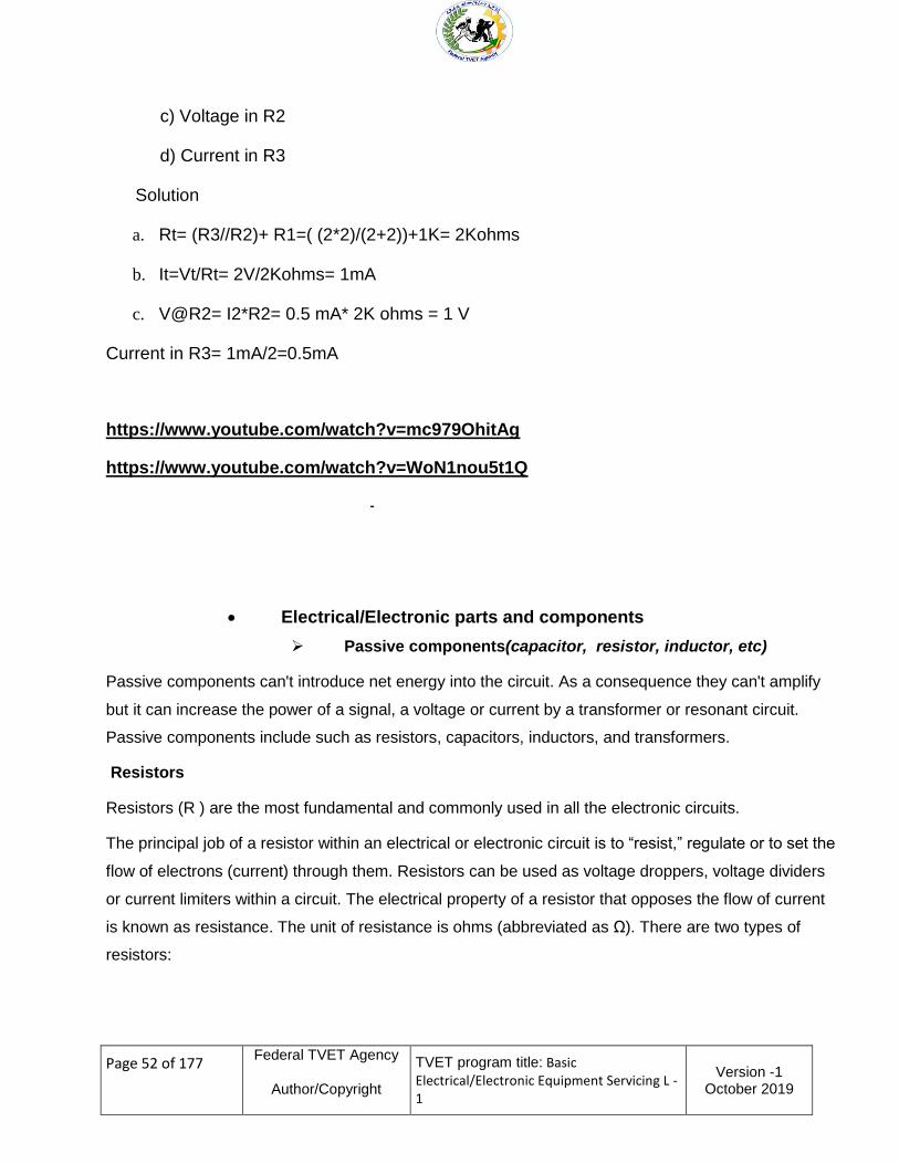
c) Voltage in R2
d) Current in R3
Solution
a Rt= (R3R2)+ R1=( (22)(2+2))+1K= 2Kohms
b It=VtRt= 2V2Kohms= 1mA
c VR2= I2R2= 05 mA 2K ohms = 1 V
Current in R3= 1mA2=05mA
httpswwwyoutubecomwatchv=mc979OhitAg
httpswwwyoutubecomwatchv=WoN1nou5t1Q
-
ElectricalElectronic parts and components
Passive components(capacitor resistor inductor etc)
Passive components cant introduce net energy into the circuit As a consequence they cant amplify
but it can increase the power of a signal a voltage or current by a transformer or resonant circuit
Passive components include such as resistors capacitors inductors and transformers
Resistors
Resistors (R ) are the most fundamental and commonly used in all the electronic circuits
The principal job of a resistor within an electrical or electronic circuit is to ldquoresistrdquo regulate or to set the
flow of electrons (current) through them Resistors can be used as voltage droppers voltage dividers
or current limiters within a circuit The electrical property of a resistor that opposes the flow of current
is known as resistance The unit of resistance is ohms (abbreviated as Ω) There are two types of
resistors
Page 53 of 177
Federal TVET Agency
AuthorCopyright
TVET program title Basic ElectricalElectronic Equipment Servicing L -1
Version -1 October 2019
Fixed resistors and
Variable resistors
Fixed resistors
Fixed resistors are those for which the value of resistance is fixed(eg carbon composition resistors
and wire wound resistors) Fixed resistors have a fixed value of resistance which is displayed in
the form of color coding for carbon resistors while it is written on the wire-wound resistors
Resistor color code
The resistance of the resistor and its tolerance are marked on the resistor with color code bands that
denotes the resistance value There are 3 types of color codes
4 bands digit digit multiplier tolerance
5 bands digit digit digit multiplier tolerance
6 bands digit digit digit multiplier tolerance temperature coefficient
Table1 Color code and tolerance
1st
Digit
2nd
Digit
3rd
Digit Multiplier Tolerance
Temperature
Coefficient
4bands
1
2
3
4
5bands 1 2 3 4 5
6bands 1 2 3 4 5 6
Black 0 0 0 times100
Brown 1 1 1 times101 plusmn1 100 ppmordmK
Red 2 2 2 times102 plusmn2 50 ppmordmK
Orange 3 3 3 times103 +3 15 ppmordmK
Yellow 4 4 4 times104 +4 25 ppmordmK
Page 54 of 177
Federal TVET Agency
AuthorCopyright
TVET program title Basic ElectricalElectronic Equipment Servicing L -1
Version -1 October 2019
Green 5 5 5 times105 plusmn05
Blue 6 6 6 times106 plusmn025 10 ppmordmK
Violet 7 7 7 times107 plusmn01 5 ppmordmK
Grey 8 8 8 times108 plusmn005
White 9 9 9 times109
Silver times10-2 plusmn10
Gold times10-1 plusmn5
None plusmn20
Figure 39 Resistor color code
Typical Example on How to Calculate the Resistor Color Codes
Reading from left to right the first band close to the edge gives the first digit in the
numerical value of R The next band marks the second digit The third band is then
decimal multiplier which gives the number of zeros after the two digits
The first band is red for 2 and the next band is violet for 7The red multiplier in the third
band means add two zeroes to 27The result can be illustrated as follows
Page 55 of 177
Federal TVET Agency
AuthorCopyright
TVET program title Basic ElectricalElectronic Equipment Servicing L -1
Version -1 October 2019
Therefore thisRvalueis2700Ωwithtolerance+5theresistortolerancemeans
theamountbywhichtheactualRcanbedifferentfromthecolour-codedvalueFor
instance thealoneresistorvalue2700Ωresistorwith+5percenttolerancecanhave
resistance 5 percent above or below the coded value
This R therefore is between 2565Ω and2835ΩThe calculations are as follows
5 percent of 2700 is 005 x 2700 = 135
For +5 percent the value is 2700 + 135 = 2835 Ω
For -5 percent the valueis2700- 135 = 2565 Ω
Variable Resistors whose resistances values can be changed from zero to
maximum with the help of a movable arm Variable resistors also called
potentiometers or rheostats employ a movable metal blade resting alone
gain go resistive film You can change the resistance by turning the knob
A wire wound potentiometer (pot) that can dissipate 5 and more watts is often referred to as a
rheostat The resistance wire is wound on an open ring of ceramic which is covered with
vitreous enable except for the track of the wiper arm Rheostats are used to control motor
speeds x-ray tube voltages ovens and many other high power applications
Variable resistor (potentiometer)
Fig 310 variable resistor
Page 56 of 177
Federal TVET Agency
AuthorCopyright
TVET program title Basic ElectricalElectronic Equipment Servicing L -1
Version -1 October 2019
a Semi variable Resistors (preset) whose value changed slightly whenever it is trimmed by
screw driver
Fig 311 variable resistor preset symbol
A small plastic screwdriver or similar tool is required to adjust presets
These are miniature versions of the standard variable resistor They are designed to be
mounted directly on to the circuit board and tuned only when the circuit is built For example
to set the colors of Computer Monitor by turning the preset in the Cathode Ray Tube (CRT)
board
Presets are much cheaper than standard variable resistors so they are sometimes
used in electronic projects where a standard variable resistor would normally be
used
Capacitor
Capacitor also known as condenser is one of the most essential components in
designing an electronic circuit Radio television and monitor circuits use a number of
capacitors Capacitor has a tendency to store electrical charge and then release it as
current in the circuit where it is connected So the use of capacitor is to store and then
release electrical charge This concept may sound simple enough but it has important
applications when the capacitor is combined with other components (inductors resistors)in
filter or timing circuits Capacitor is symbolized as shown in below and it is denoted by a
Page 57 of 177
Federal TVET Agency
AuthorCopyright
TVET program title Basic ElectricalElectronic Equipment Servicing L -1
Version -1 October 2019
letter C
HOW A CAPACITOR WORKS
There are two ways to describe how a capacitor works Both are correct and you have to combine
them to get a full picture
A capacitor has INFINITE resistance between one lead and the other
This means no current flows through a capacitor But it works in another way
Suppose you have a strong magnet on one side of a door and a piece of metal on the other By sliding
the magnet up and down of the door the metal rises and falls
The metal can be connected to a pump and you can pump water by sliding the magnet up and down
A capacitor works in exactly the same way
If you raise a voltage on one lead of a capacitor the other lead will rise to the same voltage
It works just like the magnetic field of the magnet through a door
The next concept is this
Capacitors are equivalent to a tiny rechargeable battery
They store energy when the supply-voltage is present and release it when the supply drops
These two concepts can be used in many ways and thats why capacitors perform tasks such as
filtering time-delays passing a signal from one stage to another and create many different effects in a
circuit
Unit of capacitance
Capacitance is measure in farads (F)Practically farad is a large unit The smaller units are
microfarads nano-farads and Pico-farads
1 microfarad= 11000000 farad
1 nano farad=11000000000 farad
1 Pico farad=11000000000000 farad
Page 58 of 177
Federal TVET Agency
AuthorCopyright
TVET program title Basic ElectricalElectronic Equipment Servicing L -1
Version -1 October 2019
So 001microF = 10nF = 10000pF
Micro farad can be written as MFD MF or microF or simply M Nano-farad is written as
NFPico-faradiswrittenasPFCapacitorsratedinpico-faradsarefoundinRFand
highfrequencycircuitsCapacitorsratedinmicrofaradsareincorporatedinlow- frequency and
DC circuits like power supplies audio amplifiers and digital and timer circuits
Construction
Different types for different applications
Choose for capacitance size voltage rating leakage series resistance
F
i
g
3
1
2
capacitors
Types of capacitors
There are basically two types of capacitors ie
Non-Polarized Capacitor
MICA
Paper
Ceramic
Polyester
Polystyrene
P
o
l
Page 59 of 177
Federal TVET Agency
AuthorCopyright
TVET program title Basic ElectricalElectronic Equipment Servicing L -1
Version -1 October 2019
arized Capacitor
Electrolytic capacitor
Tantalum capacitor
Fig313 different types of capacitors
Non-polarized capacitors mean that they can be inserted in to a circuit in any orientation
While polarized capacitors must be inserted in the proper orientation with
respecttoappliedvoltageIfthepolarizescapacitorsisconnectedinopposite polarity it may
explode
Voltage Rating of Capacitors
Capacitors also have a voltage rating usually stated as WV for working voltage or WVDC
This rating specifies the maximum voltage that can be applied across the capacitors
without puncturing the dielectric Voltage ratings for general purpose paper mica and
ceramic capacitors are typically 200 to 500VDC Ceramic capacitors with ratings of 1to5kv
are also available Electrolytic capacitors are commonly used in 25 50 100 150and 450v
ratings In addition 6 and 10V electrolytic capacitors are often used in transistor circuits
CAUTION
If a capacitor has a voltage rating of 63v do not put it in a 100v circuit as the insulation (called the
dielectric) will be punctured and the capacitor will short-circuit
Page 60 of 177
Federal TVET Agency
AuthorCopyright
TVET program title Basic ElectricalElectronic Equipment Servicing L -1
Version -1 October 2019
Its ok to replace a 022uF 50WV capacitor with 022uF 250WVDC
SAFETY
A capacitor can store a charge for a period of time after the equipment is turned off
High voltage electrolytic caps can pose a safety hazard These capacitors are in power supplies and
some have a resistor across them called a bleed resistor to discharge the cap after power is switched
off
If a bleed resistor is not present the cap can retain a charge after the equipment is unplugged
How to discharge a capacitor
Do not use a screwdriver to short between the terminals as this will damage the capacitor internally
and the screwdriver
Use a 1k 3watt or 5watt resistor or 100watt bulb on jumper leads and keep them connected for a few
seconds to fully discharge the electro
Test it with a voltmeter to make sure all the energy has been removed
Before testing any capacitors especially electrolytic you should look to see if any are damaged
overheated or leaking Swelling at the top of an electrolytic indicates heating and pressure inside the
case and will result in drying out of the electrolyte Any hot or warm electrolytic indicates leakage and
ceramic capacitors with portions missing indicates something has gone wrong
How to read capacitor numeric code
The non-polarized capacitor of nominal value of less than 1000pF is usually plain marked
For instant for a 220pF capacitor it will be marked 220only For capacitance values of
1000pF or more a three digit code is used The first two digits represent the two
significant digits and the third digit represents the decimal multiplier For instance 102
represents a capacitance of 10x10sup2=1000pFand104 represents a capacitance of
10x104=100000pF=01microF Basically it has the same calculation method as resistor
Page 61 of 177
Federal TVET Agency
AuthorCopyright
TVET program title Basic ElectricalElectronic Equipment Servicing L -1
Version -1 October 2019
Fig 314 ceramic capacitor
Example 1 What is the capacitance value of these capacitors marked
a22=gt22 microfarad
b330=gt330 microfarad
c471=gt47x10= 470 microfarad
d562=gt56x10sup2 = 5600 microfarad or 56 nanofarad
e103=gt10x10sup3 = 10000 microfarad or 10nanofarad
f224=gt microfarad22x10 = 220000 microfarad or 220 nanofarad or 22
g 335=gt33x10=3300000picofarador3300nanofarador33 microfarad
Electrolytic capacitor shave their capacitance voltage rating and polarity printed on the
case as shown in Figure below
Fig15 polarity of capacitors
Value of color coded capacitor can be determined in similar way as that of color coded
resistor except the voltage rating of capacitor can be indicated in the color code technique
Page 62 of 177
Federal TVET Agency
AuthorCopyright
TVET program title Basic ElectricalElectronic Equipment Servicing L -1
Version -1 October 2019
Fig16 capacitor color code
Capacitance Tolerance
Ceramicdiskcapacitorsforgeneralapplicationsusuallyhaveatoleranceof+20
percentPapercapacitorsusuallyhaveatoleranceof+10percentForcloser tolerances
micacapacitorsareusedIthastolerancevalueof+2to20percentThe
letterafterthecapacitancenumericalcodeindicatesthetoleranceieM=20
K=10J=5Soa103Kcapacitorisa10000pFor10nFor0010microF10 capacitor with 10
tolerance
ElectrolyticcapacitorshaveawidetoleranceForinstanta100microFelectrolyticwith tolerance of
ntilde10 percent +20 percent may have a capacitance of 90 to 120microF
Capacitor Equations
bullA capacitor holds charge Q proportional to the voltage across it
bullT h e capacitance C(units of Farads) is set by the construction of the capacitor
Page 63 of 177
Federal TVET Agency
AuthorCopyright
TVET program title Basic ElectricalElectronic Equipment Servicing L -1
Version -1 October 2019
Capacitor behavior
Current through capacitor proportional to rate of change in voltage across it
Capacitors act to resist changes in voltage
Capacitor current can change (very) quickly
Capacitors store energy
Table 31 symbols of capacitors
Page 64 of 177
Federal TVET Agency
AuthorCopyright
TVET program title Basic ElectricalElectronic Equipment Servicing L -1
Version -1 October 2019
INDUCTORS
Like capacitors inductors also store energy in one part of AC cycle and return it during the
next part of the cycle
Inductance is that property of a device that reacts against a change in current through the
device Inductors are components designed for use in circuits to resist changes in current and
thus serve important control functions
Inductor designed is based on the principle that a varying magnetic field induces a voltage in
any conductor in that field Thus a practical inductor may simply be a coil wire The current in
each loop of the coil produces a magnetic field that passes through neighboring loops If the
current through the coil is constant the magnetic field is constant and no action takes place A
change in the current however produces a change in the magnetic field The energy
absorbed or released from the changing magnetic field reacts against the change in current
and this is exhibited as
Page 65 of 177
Federal TVET Agency
AuthorCopyright
TVET program title Basic ElectricalElectronic Equipment Servicing L -1
Version -1 October 2019
in induced voltage (electromotive force emf) which is counter to the change in applied
voltage The inductor thus behaves as an impedance to ac current
Fig 317 Inductors
The counter emf is directly proportional to the rate of change of current through the coil (V=L [∆i∆t])
The proportionality constant is the inductance L which has the unit of henrys (H) In an ac circuit as
shown in the inductor offers reactance to alternating current The inductive reactance XL has the units
of ohms and is given by
Inductor behavior
Voltage across inductor is proportional to the rate of change of current through it
Inductors act to resist changes in current
Page 66 of 177
Federal TVET Agency
AuthorCopyright
TVET program title Basic ElectricalElectronic Equipment Servicing L -1
Version -1 October 2019
bullInductor voltage can change quickly
bullInductors store energy
Transformer
Fig 318 transformer
A transformer is an electrical device that transfers energy between two or more circuits
through electromagnetic induction
A varying current in the transformers primary winding creates a varying magnetic flux in the
core and a varying magnetic field impinging on the secondary winding This varying magnetic
field at the secondary induces a varying electromotive force (emf) or voltage in the secondary
winding The primary and secondary windings are wrapped around a core of infinitely high
magnetic permeability So that all of the magnetic flux passes through both the primary and
secondary windings
Types of transformers
Page 67 of 177
Federal TVET Agency
AuthorCopyright
TVET program title Basic ElectricalElectronic Equipment Servicing L -1
Version -1 October 2019
Fig 319 Core form = core type shell form = shell type
Closed-core transformers are constructed in core form or shell form When windings
surround the core the transformer is core form when windings are surrounded by the core
the transformer is shell form Shell form design mostly used for distribution transformer
applications due to the relative ease in stacking the core around winding coils Core form
design is more economical than shell form design for high voltage power transformer
applications at the lower end of their voltage and power rating ranges (less than or equal to
nominally 230 kV or 75 MVA) At higher voltage and power ratings shell form transformers
tend to be more prevalent Shell form design tends to be preferred for extra high voltage and
higher MVA applications because though more labor-intensive to manufacture shell form
transformers are characterized as having inherently better kVA-to-weight ratio better short-
circuit strength characteristics and higher immunity to transit damage
Active components
Active components diode transistors ICs gates
Diodes General purpose diode Rectifier diode Zener diode LED photo diode
Page 68 of 177
Federal TVET Agency
AuthorCopyright
TVET program title Basic ElectricalElectronic Equipment Servicing L -1
Version -1 October 2019
Diode is unidirectional PN-junction electronics device used in many applications Such astie
Converting AC power from the 60Hz line into DC power for radios televisions
telephone answering machines computers and many other electronic devices
Converting radio frequency signals into audible signals in radios
Used as rectifier in DC Power Supplies
In Demodulation or Detector Circuits
In clamping networks used as DC Restorers
In clipping circuits used for waveform generation
As switches in digital logic circuit
Fig 320 A pndashn junction is a boundary or interface between two types of semiconductor
material
p-type and n-type inside a single crystal of semiconductor pndashn junctions are elementary building
blocks of most semiconductor electronic devices such as diodes transistors solar cells LEDs
and integrated circuits After joining p-type and n-type semiconductors electrons from the n region
near the pndashn interface tend to diffuse into the p region The regions nearby the pndashn interfaces lose
their neutrality and become charged forming the space charge region or depletion layer
Function
Diodes allow electricity to flow in only one direction The arrow of the circuit symbol shows the
direction in which the current can flow
Forward Voltage Drop
Page 69 of 177
Federal TVET Agency
AuthorCopyright
TVET program title Basic ElectricalElectronic Equipment Servicing L -1
Version -1 October 2019
When a forward voltage is applied to diode a small voltage experiences across a conducting diode it
is called the forward voltage drop and is about 07V for all normal diodes which are made from
silicon The forward voltage drop of a diode is almost constant whatever the current passing through
the diode so they have a very steep characteristic (current-voltage graph)
Fig 321 forward voltage drop
Reverse Voltage
When a reverse voltage is applied a perfect diode does not conduct but all real diodes leak a very tiny
current of a few microA or less This can be ignored in most circuits because it will be very much smaller
than the current flowing in the forward direction However all diodes have a maximum reverse
voltage (usually 50V or more) and if this is exceeded the diode will fail and pass a large current in the
reverse direction this is called breakdown
Ordinary diodes can be split into two types Signal diodes which pass small currents of 100mA or less
and Rectifier diodes which can pass large currents In addition there are other types of diodes as such
LEDs Zener diodes Tunnel diode PIN diode Photo diode and Varicap diode etc
Signal diodes (small current)
Signal diodes are used to process information (electrical signals) in circuits so they are only required
to pass small currents of up to 100mA
General purpose signal diodes such as the 1N4148 are made from silicon and have a forward voltage
drop of 07V
Page 70 of 177
Federal TVET Agency
AuthorCopyright
TVET program title Basic ElectricalElectronic Equipment Servicing L -1
Version -1 October 2019
Germanium diodes such as the OA90 have a lower forward voltage drop of 02V and this makes
them suitable to use in radio circuits as detectors which extract the audio signal from the weak radio
signal
For general use where the size of the forward voltage drop is less important silicon diodes are better
because they are less easily damaged by heat when soldering they have a lower resistance when
conducting and they have very low leakage currents when a reverse voltage is applied
Biasing of Diode the process of applying an external voltage is called as ldquobiasingrdquo
There are two ways in which we can bias a pn junction diode
Forward bias
Reverse bias
Forward Bias ndash The voltage potential is connected positive (+ve) to the P-type material and negative
(-ve) to the N-type material across the diode which has the effect of Decreasing the PN junction
diodesrsquos width Reverse Bias ndash The voltage potential is connected negative (-ve) to the P-type
material and positive (+ve) to the N-type material across the diode which has the effect of Increasing
the PN junction diodersquos width
Fig322 Forward amp Reverse bias amp V-I characteristics of PN junction Diode
Forward Biased PN Junction Diode
When a diode is connected in a Forward Bias condition a negative voltage is applied to the
n-type material and a positive voltage is applied to the p-type material If this external voltage
becomes greater than the value of the potential barrier approx 07 volts for silicon and 03
Page 71 of 177
Federal TVET Agency
AuthorCopyright
TVET program title Basic ElectricalElectronic Equipment Servicing L -1
Version -1 October 2019
volts for germanium the potential barriers opposition will be overcome and current will start to
flow
Reverse
Fig23 Forward biasing voltage
Biased PN Junction Diode
When a diode is connected in a Reverse Bias condition a positive voltage is applied to the N type
material and a negative voltage is applied to the P-type material The positive voltage applied to the N-
type material attracts electrons towards the positive electrode and away from the junction while the
holes in the P-type end are also attracted away from the junction towards the negative electrode Thus
The depletion layer grows wider due to a lack of electrons and holes and presents a high impedance
path almost an insulator
The result is that a high potential barrier is created thus preventing current from flowing through the
semiconductor material
A high resistance value to the PN junction and practically zero current flows through the junction
diode with an increase in bias voltage However a very small leakage current does flow through the
junction which can be measured in microamperes ( microA )
Page 72 of 177
Federal TVET Agency
AuthorCopyright
TVET program title Basic ElectricalElectronic Equipment Servicing L -1
Version -1 October 2019
Fig 324 Reverse biasing voltage
Junction Diode Summary
The PN junction region of a Junction Diode has the following important characteristics
Semiconductors contain two types of mobile charge carriers Holes and Electrons
The holes are positively charged while the electrons negatively charged
A semiconductor may be doped with donor impurities such as Antimony (N-type doping) so
that it contains mobile charges which are primarily electrons
A semiconductor may be doped with acceptor impurities such as Boron (P-type doping) so that
it contains mobile charges which are mainly holes
The junction region itself has no charge carriers and is known as the depletion region
The junction (depletion) region has a physical thickness that varies with the applied voltage
When a diode is Zero Biased no external energy source is applied and a natural
Potential Barrier is developed across a depletion layer which is approximately 05 to 07v for silicon
diodes and approximately 03 of a volt for germanium diodes
When a junction diode is Forward Biased the thickness of the depletion region reduces and
the diode acts like a short circuit allowing full current to flow
When a junction diode is Reverse Biased the thickness of the depletion region increases and
the diode acts like an open circuit
Page 73 of 177
Federal TVET Agency
AuthorCopyright
TVET program title Basic ElectricalElectronic Equipment Servicing L -1
Version -1 October 2019
Fig 325 Voltage-current characteristics of silicon and germanium diodes and its symbol
Rectifier diode- Convert AC to DC
The conversion of bidirectional alternating current (ac) into unidirectional direct current (dc)is called
rectification Electronic devices can convert ac power into dc power with very high efficiency
Half wave rectifier In this type the rectifier conducts current only during the + ve half cycles of the
ac supply In this type the rectifier utilizes both half cycles of ac input voltage to produce the dc
output
Fig 326 Half wave rectifier
Page 74 of 177
Federal TVET Agency
AuthorCopyright
TVET program title Basic ElectricalElectronic Equipment Servicing L -1
Version -1 October 2019
Here ndash ve half cycles are suppressed ie during ndashve half cycle no current passes through the diode
hence no voltage appears across the load
Max rectifier Efficiency= Max dc output power ac input power =406
Full Wave Rectifier
a) Full Wave Rectifier(Centre Tapped Type)
During the positive half cycle of the supply(look at the following figure a) diodeD1 conducts while
diodeD2 is reverse biased and the current flows through the load as shown Similarly during the
negative half cycle of the supply diodeD2 conducts while diodeD1 is reverse biased and the current
flows through the load as shown
b) Bridge Full wave rectifier
Fig327 Full wave rectifier
During the positive half cycle of the supply(look at figure b above) diodes D1 and D2 conduct in
series while diodes D3 and D4 are reverse biased and the current flows through the load as shown
below
Page 75 of 177
Federal TVET Agency
AuthorCopyright
TVET program title Basic ElectricalElectronic Equipment Servicing L -1
Version -1 October 2019
During the negative half cycle of the supply diodes D3 and D4 conduct in series but diodes D1 and
D2 switch ldquoOFFrdquo as they are now reversing biased The current flowing through the load is the same
direction as before
Notice the detail discussion about rectifier is presented in UC ldquoACDC Power supplyrdquo
Zener diodes
Zener diodes or as they may sometimes be called reference diodes operate like an ordinary diode in
the forward bias direction They have the normal turn on voltage of 06 volts for a silicon diode
However in the reverse direction their operation is rather different Zener diodes are used to maintain a
fixed voltage They are designed to breakdown in a reliable and nondestructive way so that they can
be used in reverse to maintain a fixed voltage across their terminals The diagram shows how they
are connected with a resistor in series to limit the current
Zener diodes can be distinguished from ordinary diodes by their code and breakdown voltage which
are printed on them Zener diode codes begin BZX or BZY Their breakdown voltage is printed with
V in place of a decimal point so 4V7 means 47V for example Some of Zener diodes are rated by
their breakdown voltage and maximum power
The minimum voltage available is 27V
Power ratings of 400mW and 13W are common
Zener v-i characteristic
The vi characteristic of the Zener to voltage reference diode is the key to its operation In the forward
direction the diode performs like any other but it is in the reverse direction where its specific
performance parameters can be utilized
Page 76 of 177
Federal TVET Agency
AuthorCopyright
TVET program title Basic ElectricalElectronic Equipment Servicing L -1
Version -1 October 2019
Fig 28 Characteristics of zener diode
Application of Zener
Used in Voltage Stabilizer Clipper Circuit Reference voltage limiter circuits
Simple Zener diode circuit for voltage regulator
When used in a regulator circuit the Zener diode must have the current entering it limited If a perfect
voltage source was placed across it then it would draw excessive current once the
Break down voltage had been reached To overcome this Zener diode must be driven by a current
source This will limit the current to the chosen value The value of the series resistor is simple to
calculate It is simply the voltage across the resistor divided by the current required The level of
Zener current can be chosen to suit the circuit and the Zener diode used
Fig 328 Zener diode in regulator circuit
Page 77 of 177
Federal TVET Agency
AuthorCopyright
TVET program title Basic ElectricalElectronic Equipment Servicing L -1
Version -1 October 2019
Light emitting diode (LED)
A light emitting diode (LED) is known to be one of the best optoelectronic devices The device is
capable of emitting a fairly narrow bandwidth of visible or invisible light when its internal diode junction
attains a forward electric current or voltage The visible lights that an LED emits are usually orange
red yellow or green The invisible light includes the infrared light
We know that a P-N junction can connect the absorbed light energy into its proportional electric
current The same process is reversed here That is the P-N junction emits light when energy is
applied on it This phenomenon is generally called electro luminance which can be defined as the
emission of light from a semi-conductor under the influence of an electric field The charge carriers
recombine in a forward P-N junction as the electrons cross from the N-region and recombine with the
holes existing in the P-region Free electrons are in the conduction band of energy levels while holes
are in the valence energy band Thus the energy level of the holes will be lesser than the energy levels
of the electrons Some part of the energy must be dissipated in order to recombine the electrons and
the holes This energy is emitted in the form of heat and light
The electrons dissipate energy in the form of heat for silicon and germanium diodes But in Galium-
Arsenide-phosphorous (GaAsP) and Gallium-phosphorous (GaP) semiconductors the electrons
dissipate energy by emitting photons
LED Circuit Symbol
The circuit symbol of LED consists of two arrow marks which indicate the radiation emitted by the
diode
Page 78 of 177
Federal TVET Agency
AuthorCopyright
TVET program title Basic ElectricalElectronic Equipment Servicing L -1
Version -1 October 2019
Fig 330 The forward bias Voltage-Current (V-I) curve and the output characteristics curve is
shown in the figure above
LED as an Indicator
The circuit shown below is one of the main applications of LED The circuit is designed by wiring it in
inverse parallel with a normal diode to prevent the device from being reverse biased The value of the
series resistance should be half relative to that o f a DC circuit
Fig 331 LED Circuit
Advantages of LED
Page 79 of 177
Federal TVET Agency
AuthorCopyright
TVET program title Basic ElectricalElectronic Equipment Servicing L -1
Version -1 October 2019
Very low voltage and current are enough to drive the LED
Voltage range ndash 1 to 2 volts
Current ndash 5 to 20 milli amperes
Total power output will be less than 150 milli watts
The response time is very less ndash only about 10 nanoseconds
The device does not need any heating and warm up time
Miniature in size and hence light weight
Have a rugged construction and hence can withstand shock and vibrations
An LED has a life span of more than 20 years
Disadvantages
A slight excess in voltage or current can damage the device
The device is known to have a much wider bandwidth compared to the laser
The temperature depends on the radiant output power and wavelength
Photodiodes
A photodiode is a semiconductor device that converts light into current The current is generated
when photons are absorbed in the photodiode A small amount of current is also produced when no
light is present
A photodiode is a diode optimized to produce an electron current flow in response to irradiation by
ultraviolet visible or infrared light Silicon is most often used to fabricate photodiodes though
germanium and gallium arsenide can be used The junction through which light enters the
semiconductor must be thin enough to pass most of the light on to the active region (depletion region)
where light is converted to electron hole pairs
Page 80 of 177
Federal TVET Agency
AuthorCopyright
TVET program title Basic ElectricalElectronic Equipment Servicing L -1
Version -1 October 2019
In photo diode construction shown in the figure bellow shallow P-type diffusion into an N-type wafer
produces a PN junction near the surface of the wafer
The P-type layer needs to be thin to pass as much light as possible A heavy N+ diffusion on the back
of the wafer makes contact with metallization The top metallization may be a fine grid of metallic
fingers on the top of the wafer for large cells In small photodiodes the top contact might be a sole
bond wire contacting the bare P-type silicon top
Fig 332 Photodiode Schematic symbol and cross section (below Photo diodes)
Applications
Photodiodes are used in consumer electronics devices such as compact disc players smoke
detectors and the receivers for infrared remote control devices used to control equipment from
televisions to air conditioners For many applications either photodiodes or photoconductors may be
used Either type of photo sensor may be used for light measurement as in camera light meters or to
respond to light levels as in switching on street lighting after dark
Page 81 of 177
Federal TVET Agency
AuthorCopyright
TVET program title Basic ElectricalElectronic Equipment Servicing L -1
Version -1 October 2019
Photodiodes may contain optical filters built-in lenses and may have large or small surface areas
Photodiodes usually have a slower response time as its surface area increases The common
traditional solar cell used to generate electric solar power is a large area photodiode
Transistors
Transistors are solid-state active non-linear devices that facilitate signal amplification and act as
switching (controlling) device
There are two main classes of transistors bipolar-junction transistors (BJT) and field-effect transistors
(FET)
Bipolar Junction Transistors (BJT)
If we join together two individual signal diodes back-to-back this will give us two PN-junctions
connected together in series that share a common P or N terminal The fusion of these two diodes
produces a three layer two junctions three terminal device forming the basis of a bipolar junction
Transistor or BJT for short
The word Transistor is an acronym and is a combination of the words Transfer Varistor used to
describe their mode of operation way back in their early days of development There are two basic
types of bipolar transistor construction NPN and PNP which basically describes the physical
arrangement of the P-type and N-type semiconductor materials from which they are made
The Bipolar Transistor basic construction consists of two PN-junctions producing three connecting
terminals with each terminal being given a name to identify it from the other two These three terminals
are known and labeled as the Emitter (E ) the Base ( B ) and the Collector ( C ) respectively
Page 82 of 177
Federal TVET Agency
AuthorCopyright
TVET program title Basic ElectricalElectronic Equipment Servicing L -1
Version -1 October 2019
Fig 333 BJT construction
The construction and circuit symbols for both the NPN and PNP bipolar transistor are given above with
the arrow in the circuit symbol always showing the direction of conventional current flow between the
base terminal and its emitter terminal The direction of the arrow always points from the positive P-type
region to the negative N-type region for both transistor types exactly the same as for the standard
diode symbol
Bipolar Transistors are current regulating devices that control the amount of current flowing through
them in proportion to the amount of biasing voltage applied to their base terminal acting like a current-
controlled switch The principle of operation of the two transistors types NPN and PNP is exactly the
same the only difference being in their biasing and the polarity of the power supply for each type
Transistors are three terminal active devices made from different semiconductor materials that has an
ability to change between an insulator or a conductor states by the application of a small signal
voltage between base and emitter which enables it to have two basic functions switching (digital
Page 83 of 177
Federal TVET Agency
AuthorCopyright
TVET program title Basic ElectricalElectronic Equipment Servicing L -1
Version -1 October 2019
electronics) or amplification (analogue electronics) Then bipolar transistors have the ability to
operate within three different regions
1 Active Region - the transistor operates as an amplifier and Ic = szligIb
2 Saturation - the transistor is fully-ON operating as a switch and Ic = I(saturation)
3 Cut-off - the transistor is fully-OFF operating as a switch and Ic = 0
Fig3 35 Output characteristic curves for a typical BJT
Integrated circuits
An integrated circuit (IC) sometimes called a chip or microchip is a semiconductor wafer on which
thousands or millions of tiny resistors capacitors and transistors are fabricated An IC can function as
an amplifier oscillator timer counter computer memory or microprocessor A particular IC is
categorized as either linear analog or digital depending on its intended application
Page 84 of 177
Federal TVET Agency
AuthorCopyright
TVET program title Basic ElectricalElectronic Equipment Servicing L -1
Version -1 October 2019
ICs are of Linear digital and mixed types Linear ICs have continuously variable output (theoretically
capable of attaining an infinite number of states) that depends on the input signal level As the term
implies the output signal level is a linear function of the input signal level Linear ICs are used as
audio-frequency (AF) and radio-frequency (RF) amplifiers The operational amplifier (op amp) is a
common device in these applications
Digital ICs operate at only a few defined levels or states rather than over a continuous range of signal
amplitudes These devices are used in computers computer networks modems and frequency
counters The fundamental building blocks of digital ICs are logic gates which work with binary data
that is signals that have only two different states called low (logic 0) and high (logic 1) or OFF and
ON or this can be represented by False and True
Page 85 of 177
Federal TVET Agency
AuthorCopyright
TVET program title Basic ElectricalElectronic Equipment Servicing L -1
Version -1 October 2019
Truth Table
Digital gates use one or more inputs to produce an output
Truth tables are the easiest way of describing how a gate behaves The truth table gives the
state of the output for all possible values of inputs
Conventionally letters ABChellipetc are used for inputs and Q for output
Page 86 of 177
Federal TVET Agency
AuthorCopyright
TVET program title Basic ElectricalElectronic Equipment Servicing L -1
Version -1 October 2019
Page 87 of 177
Federal TVET Agency
AuthorCopyright
TVET program title Basic ElectricalElectronic Equipment Servicing L -1
Version -1 October 2019
Universal Gates
A universal gate is a gate which can implement any Boolean function without need to use any other
gate type
The NAND and NOR gates are universal gates
In practice this is advantageous since NAND and NOR gates are economical and easier to fabricate
and are the basic gates used in all IC digital logic families
In fact an AND gate is typically implemented as a NAND gate followed by an inverter not the other
way around
Likewise an OR gate is typically implemented as a NOR gate followed by an inverter not the other
way around
NAND Gate is a Universal Gate
To prove that any Boolean function can be implemented using only NAND gates we will show that the
AND OR and NOT operations can be performed using only these gates
Implementing an Inverter Using only NAND Gate
The figure shows two ways in which a NAND gate can be used as an inverter (NOT gate)
Page 88 of 177
Federal TVET Agency
AuthorCopyright
TVET program title Basic ElectricalElectronic Equipment Servicing L -1
Version -1 October 2019
1 All NAND input pins connect to the input signal A gives an output Arsquo
2 One NAND input pin is connected to the input signal A while all other input pins are connected to
logic 1 The output will be Arsquo
Implementing AND Using only NAND Gates
An AND gate can be replaced by NAND gates as shown in the figure (The AND is replaced by a
NAND gate with its output complemented by a NAND gate inverter)
Implementing OR Using only NAND Gates
Page 89 of 177
Federal TVET Agency
AuthorCopyright
TVET program title Basic ElectricalElectronic Equipment Servicing L -1
Version -1 October 2019
An OR gate can be replaced by NAND gates as shown in the figure (The OR gate is replaced by a
NAND gate with all its inputs complemented by NAND gate inverters)
Thus the NAND gate is a universal gate since it can implement the AND OR and NOT
functions
Implementing an Inverter Using only NOR Gate
The figure shows two ways in which a NOR gate can be used as an inverter (NOT gate)
1 All NOR input pins connect to the input signal A gives an output Arsquo
2 One NOR input pin is connected to the input signal A while all other input pins are connected to
logic 0 The output will be Arsquo
Page 90 of 177
Federal TVET Agency
AuthorCopyright
TVET program title Basic ElectricalElectronic Equipment Servicing L -1
Version -1 October 2019
Implementing OR Using only NOR Gates
An OR gate can be replaced by NOR gates as shown in the figure (The OR is replaced by a NOR
gate with its output complemented by a NOR gate inverter)
Implementing AND Using only NOR Gates
An AND gate can be replaced by NOR gates as shown in the figure (The AND gate is replaced by a
NOR gate with all its inputs complemented by NOR gate inverters)
Thus the NOR gate is a universal gate since it can implement the AND OR and
NOT functions
Equivalent Gates
The shown figure summarizes important cases of gate equivalence Note that bubbles indicate a
complement operation (inverter)
Page 91 of 177
Federal TVET Agency
AuthorCopyright
TVET program title Basic ElectricalElectronic Equipment Servicing L -1
Version -1 October 2019
A NAND gate is equivalent to an inverted-input OR gate
An AND gate is equivalent to an inverted-input NOR gate
A NOR gate is equivalent to an inverted-input AND gate
An OR gate is equivalent to an inverted-input NAND gate
Two NOT gates in series are same as a buffer because they cancel each other as Arsquorsquo =
A
Page 92 of 177
Federal TVET Agency
AuthorCopyright
TVET program title Basic ElectricalElectronic Equipment Servicing L -1
Version -1 October 2019
Self-Check -3 Written Test
Directions Answer all the questions listed below
I Choose the best option amp circle the letter of your choice
1 What is the name for the flow of electrons in an electric circuit
A Voltage B Resistance C Capacitance D Current
2 Which of the following will remain the same in all parts of a series circuit
(A) Voltage (B) Current (C) Power (D) Resistance
3 A battery is a source of (A) DC voltage (B) 1 φ AC voltage (C) 3 φ AC voltage (D)
AC or DC voltage
4 What is the name of the pressure that forces electrons to flow through a circuit
A Magneto motive force or inductance B Electromotive force or voltage
C Farad force or capacitance D Thermal force or heat
5 What limits the current that flows through a circuit for a particular applied DC voltage
Page 93 of 177
Federal TVET Agency
AuthorCopyright
TVET program title Basic ElectricalElectronic Equipment Servicing L -1
Version -1 October 2019
A Reliance B Reactance C Saturation D Resistance
6 What are three good electrical conductors
A Copper gold mica B Gold silver wood
C Gold silver aluminum D Copper aluminum paper
7 What are four good electrical insulators
A Glass air plastic porcelain B Glass wood copper porcelain
C Paper glass air aluminum D Plastic rubber wood carbon
____8 Which of the following symbols represents a NOR gate
A) B) B)
C) D)
___ 9 What type of logic gate does this symbol represent
A) Exclusive OR C) OR
B) Exclusive NOR D) NOR
10 ----------is a semiconductor device that converts light into current
A Rectifier Diode B A photodiode CZener diode D Tunnel Diode
Score = ___________
Rating ____________
Note Satisfactory rating 10 and above
points Unsatisfactory - below 10 points
Page 94 of 177
Federal TVET Agency
AuthorCopyright
TVET program title Basic ElectricalElectronic Equipment Servicing L -1
Version -1 October 2019
Information Sheet-4 Using appropriate range of methods in testing electrical electronic
circuits amp parts
41 Introduction
Digital multimeter is the most common testing instrument used to test every
electronic component In order to test these components it is important to know
the different ranges of multimeter shown below
Page 95 of 177
Federal TVET Agency
AuthorCopyright
TVET program title Basic ElectricalElectronic Equipment Servicing L -1
Version -1 October 2019
42 Using appropriate range of methods in testing electrical electronic circuits
TESTING AC AND DC SOURCE
In order to accurately test AC and DC voltage we use the digital meter as it shows more precise
reading than the analogue meter Set your multi meter to its appropriate function (DCV or ACV) then
select the proper range Note an auto ranging digital meter will select its own range Place your test
leads across (in parallel with) the part under test as shown in all the photos below and read voltage
directly from the panel meter
Page 96 of 177
Federal TVET Agency
AuthorCopyright
TVET program title Basic ElectricalElectronic Equipment Servicing L -1
Version -1 October 2019
Using appropriate range of methods in testing electrical electronic parts
Testing and troubleshooting are the areas of maintenance that require the greatest technical
skill
Testing procedures are referred to as measurements tests and checks The definitions of
these terms often overlap depending on their use and the results obtained
Electronic devices are simplified as components in which electrical conduction takes place by
motions of electrons through them
Page 97 of 177
Federal TVET Agency
AuthorCopyright
TVET program title Basic ElectricalElectronic Equipment Servicing L -1
Version -1 October 2019
Analog and Digital meters behave quite differently when testing linear and nonlinear devices
like diodes and transistors Analog multimeter or VOM (Volt Ohm milliammeter) is the most
widely used electrical instrument in design development repair service and maintenance
laboratories It is usually a moving coil meter which by switching and the selection of probe
jacks can become a dc voltmeter an AC voltmeter and DC milli-ameteror an ohm meter
Digital Multi-meters are characterized by high input impedance and better accuracy and
resolution They usually have auto-ranging auto-polarity and auto-zero facilities which means
that the user need only set the function switch and get the reading The digital multimeter
converts an input analog signal into its digital equivalent and displays it
Safety Considerations
None of the tests described in this document require probing live circuits Safety guidelines for
high voltage andor line powered equipment first
Page 98 of 177
Federal TVET Agency
AuthorCopyright
TVET program title Basic ElectricalElectronic Equipment Servicing L -1
Version -1 October 2019
Before touching probing or unsoldering any component make sure the equipment is
unplugged and any large capacitors have been safely discharged Not only can coming in
contact with a live circuit or charged capacitor run your entire day your test equipment could
be damaged or destroyed as well
Testing (measuring) resistors
1 Adjust the meter in resistance range which is greater than the expected value
2 Turn a circuit off before measuring resistance
3 Hold the leads of the meter across the resistor legs
4 Read the values of the resistor
If the reading is equal to the expected one the resistor is normal and we can use the reading
but if the value is unexpectedly large (infinite) or very small (approximately zero) it is expected
to be open or short circuit faulty respectively
Notice if a resistor is not disconnected from the circuit during measurement and any voltage
is present the value of resistance will be incorrect You cannot measure a component while it
is in-circuit You should disconnect at least one of the leg of the resistor to be measure from a
circuit
Page 99 of 177
Federal TVET Agency
AuthorCopyright
TVET program title Basic ElectricalElectronic Equipment Servicing L -1
Version -1 October 2019
This is because the meter is actually measuring a voltage across a component and calling it
a resistance
The voltage comes from the battery inside the meter If any other voltage is present the meter
will produce a false reading If you are measuring the resistance of a component while still in
circuit (with the power off) the reading will be lower than the true reading
1 Do not measure the resistance of a battery The resistance of a battery (called the internal
impedance) is not measured as shown in the diagrams above It is measured by creating a current-
flow and measuring the voltage across the battery Placing a multimeter set to resistance (across a
battery) will destroy the meter
2 Do not try to measure the resistance of any voltage or any supply
A BURNT RESISTOR - normally and technically called a burnt-out resistor
The resistance of a burnt resistor can sometimes be determined by scraping away the outer coating -
if the resistor has a spiral of resistance-material You may be able to find a spot where the spiral has
been damaged
Page 100 of 177
Federal TVET Agency
AuthorCopyright
TVET program title Basic ElectricalElectronic Equipment Servicing L -1
Version -1 October 2019
Clean the spot (burnt section of the spiral) very carefully and make sure you can get a good contact
with the spiral and the tip of your probe Measure from one lead of the resistor to the end of the
damaged spiral Then measure from the other lead to the other end of the spiral
Add the two values and you have an approximate value for the resistor You can add a small amount
for the damaged section
This process works very well for damaged wire-wound resistors They can be pulled apart and each
section of the resistance-wire (nichrome wire) measured and added to get the full resistance
There is another way to determine the value of a damaged resistor
Get a set of resistors of the same wattage as the damaged component and start with a high value Its
handy to know if the resistor is in the range 10ohm to 100ohms or 1k to 10k etc but this is not
essential
Start with a very high value and turn the circuit ON You can perform voltage tests and if you know the
expected output voltage decrease the resistance until this voltage is obtained
If you do not know the expected voltage keep reducing the value of resistance until the circuit works
as designed
This is the best advice in a situation where you do not know the value of a resistor
Page 101 of 177
Federal TVET Agency
AuthorCopyright
TVET program title Basic ElectricalElectronic Equipment Servicing L -1
Version -1 October 2019
There is a third way to determine the value and this requires measuring the voltage drop across the
resistor and the current-flow By multiplying the two you will get a wattage and this must be less than
the wattage of the resistor being replaced
TESTING POTENTIOMETERS (variable resistors)
To check the value of a variable resistor it should be removed from circuit or at least 2 legs should be
removed A Rheostat is a variable resistor using only one end and the middle connected to a circuit
The resistance between the two outside pins is the value marked on the component and the center leg
will change from nearly zero to the full resistance as the shaft is rotated Pots generally suffer from
crackle when turned and this can be fixed by spraying up the shaft and into the pot via the shaft with
a tube fixed to a can of spray-lubricant (contact cleaner)
Pre-set pots and trim pots are miniature versions of a potentiometer and they are all tested the
same
TESTING A CAPACITOR
There are two things you can test with a multimeter
1 A short-circuit within the capacitor
2 Capacitor values above 1u
You can test capacitors in-circuit for short-circuits Use the x1 ohms range
To test a capacitor for leakage you need to remove it or at least one lead must be removed from the
circuit Use the x10k range on an analogue or digital multimeter
For values above 1u you can determine if the capacitor is charging by using an analogue meter The
needle will initially move across the scale to indicate the cap is charging then go to no deflection
Any permanent deflection of the needle will indicate leakage
You can reverse the probes to see if the needle moves in the opposite direction This indicates it has
been charged Values below 1u will not respond to charging and the needle will not deflect
Page 102 of 177
Federal TVET Agency
AuthorCopyright
TVET program title Basic ElectricalElectronic Equipment Servicing L -1
Version -1 October 2019
This does not work with a digital meter as the resistance range does not output any current and the
electrolytic does not charge
Rather than spending money on a capacitance meter it is cheaper to replace any suspect capacitor or
electrolytic
Capacitors can produce very unusual faults and no piece of test equipment is going to detect the
problem
In most cases it is a simple matter to solder another capacitor across the suspect component and
view or listen to the result
This saves all the worry of removing the component and testing it with equipment that cannot possibly
give you an accurate reading when the full voltage and current is not present
Finding the Value of a Capacitor
If you want to find the value of a surface-mount capacitor or one where the markings have been
removed you will need a CAPACITANCE METER Here is a simple circuit that can be added to your
meter to read capacitor values from 10p to 10u
ADD-ON CAPACITANCE METER
Page 103 of 177
Federal TVET Agency
AuthorCopyright
TVET program title Basic ElectricalElectronic Equipment Servicing L -1
Version -1 October 2019
REPLACING A CAPACITOR
Always replace a capacitor with the exact same type
A capacitor may be slightly important in a circuit or it might be extremely critical
A manufacturer may have taken years to select the right type of capacitor due to previous failures
A capacitor just doesnt have a value of capacitance
It may also has an effect called tightening of the rails
In other words a capacitor has the ability to react quickly and either absorb or deliver energy to
prevent spikes or fluctuations on the rail
This is due to the way it is constructed Some capacitors are simply plates of metal film while others
are wound in a coil Some capacitors are large while others are small
They all react differently when the voltage fluctuates
Not only this but some capacitors are very stable and all these features go into the decision for the
type of capacitor to use
You can completely destroy the operation of a circuit by selecting the wrong type of capacitor
No capacitor is perfect and when it gets charged or discharged it appears to have a small value of
resistance in series with the value of capacitance This is known as
ESR and stands for EQUIVALENT SERIES RESISTANCE This effectively makes the capacitor
slightly slower to charge and discharge
The only solution is to replace a capacitor with an identical type
However if you get more than one repair with identical faults you should ask other technicians if the
original capacitor comes from a faulty batch
Some capacitor is suitable for high frequencies others for low frequencies
TESTING COILS INDUCTORS and YOKES
Page 104 of 177
Federal TVET Agency
AuthorCopyright
TVET program title Basic ElectricalElectronic Equipment Servicing L -1
Version -1 October 2019
You can test this component for continuity between the ends of the winding and also make sure there
is no continuity between the winding and the core
It is important to understand the turns are insulated but a slight fracture in the insulation can cause two
turns to touch each other and this is called a SHORTED TURN or you can say the inductor has
SHORTED TURNS
When this happens the inductor allows the circuit to draw MORE CURRENT This causes the fuse to
blow
The quickest way to check an inductor is to replace it but if you want to measure the inductance you
can use an INDUCTANCE METER You can then compare the inductance with a known good
component
An inductor with a shorted turn will have a very low or zero inductance however you may not be able
to detect the fault when it is not working in a circuit as the fault may be created by a high voltage
generated between two of the turns
Faulty yokes (both horizontal and vertical windings) can cause the picture to reduce in size andor
bend or produce a single horizontal line
A TV or monitor screen is the best piece of Test Equipment as it has identified the fault It is pointless
trying to test the windings further as you will not be able to test them under full operating conditions
MEASURING AND TESTING INDUCTORS
Inductors are measured with an INDUCTANCE METER but the value of some inductors is very small
and some Inductance Meters do not give an accurate reading
The solution is to measure a larger inductor and note the reading Now put the two inductors in
SERIES and the values ADD UP - just like resistors in SERIES This way you can measure very small
inductors
TESTING ACTIVE COMPONENTS
TESTING DIODES
Page 105 of 177
Federal TVET Agency
AuthorCopyright
TVET program title Basic ElectricalElectronic Equipment Servicing L -1
Version -1 October 2019
Diodes can have 4 different faults
1 Open circuit in both directions
2 Low resistance in both directions
3 Leaky
4 Breakdown under load
TESTING A DIODE ON AN ANALOGUE METER
Testing a diode with an Analogue Multimeter can be done on any of the resistance ranges [The high
resistance range is best - it sometimes has a high voltage battery for this range but this does not affect
our testing]
There are two things you must remember
1 When the diode is measured in one direction the needle will not move at all The technical term for
this is the diode is reverse biased It will not allow any current to flow Thus the needle will not move
When the diode is connected around the other way the needle will swing to the right (move up scale)
to about 80 of the scale This position represents the voltage drop across the junction of the diode
and is NOT a resistance value If you change the resistance range the needle will move to a slightly
different position due to the resistances inside the meter The technical term for this is the diode is
forward biased This indicates the diode is not faulty
Page 106 of 177
Federal TVET Agency
AuthorCopyright
TVET program title Basic ElectricalElectronic Equipment Servicing L -1
Version -1 October 2019
The needle will swing to a slightly different position for a normal diode compared to a Schottky diode
This is due to the different junction voltage drops
However we are only testing the diode at very low voltage and it may break-down
when fitted to a circuit due to a higher voltage being present or due to a high current flowing
2 The leads of an Analogue Multimeter have the positive of the battery connected
to the black probe and the readings of a good diode are shown in the following two diagrams
TESTING A DIODE ON A DIGITAL METER
Testing a diode with a Digital Meter must be done on the DIODE setting as a digital meter does not
deliver a current through the probes on some of the resistance settings and will not produce an
accurate reading
The best thing to do with a suspect diode is to replace it This is because a diode has a number of
characteristics that cannot be tested with simple equipment Some diodes have a fast recovery for
use in high frequency circuits They conduct very quickly and turn off very quickly so the waveform is
processed accurately and efficiently
If the diode is replaced with an ordinary diode it will heat up as does not have the high-speed
characteristic
Page 107 of 177
Federal TVET Agency
AuthorCopyright
TVET program title Basic ElectricalElectronic Equipment Servicing L -1
Version -1 October 2019
Other diodes have a low drop across them and if an ordinary is used it will heat up
Most diodes fail by going SHORT-CIRCUIT This can be detected by a low resistance (x1 or x10
Ohms range) in both directions
A diode can also go OPEN CIRCUIT To locate this fault place an identical diode across the diode
being tested
A leaky diode can be detected by a low reading in one direction and a slight reading the other
direction
However this type of fault can only be detected when the circuit is working The output of the circuit will
be low and sometimes the diode heats up (more than normal)
A diode can go open under full load conditions and perform intermittently
Testing BJT Using Analog Meter
Step 1 - FINDING THE BASE and Determining NPN or PNP
Get an unknown transistor and test it with a multimeter set to x10
Try the 6 combinations and when you have the black probe on a pin and the red probe touches the
other pins and the meter swings nearly full scale you have an NPN transistor The black probe is
BASE
If the red probe touches a pin and the black probe produces a swing on the other two pins you have a
PNP transistor The red probe is BASE
If the needle swings FULL SCALE or if it swings for more than 2 readings the transistor is FAULTY
Page 108 of 177
Federal TVET Agency
AuthorCopyright
TVET program title Basic ElectricalElectronic Equipment Servicing L -1
Version -1 October 2019
Step 2 - FINDING THE COLLECTOR and EMITTER
1 Set the meter to x10k
For an NPN transistor place the leads on the transistor and when you press hard on the two leads
shown in the diagram below the needle will swing almost full scale
You have found collector Base and emitter
For a PNP transistor set the meter to x10k place the leads on the transistor and when you press
hard on the two leads shown in the diagram below the needle will swing almost full scale
Page 109 of 177
Federal TVET Agency
AuthorCopyright
TVET program title Basic ElectricalElectronic Equipment Servicing L -1
Version -1 October 2019
You have found collector Base and emitter
Notice In the same way you can test using digital multimeter but the black lead is negative and the
red lead is positive
SIMPLEST TRANSISTOR TESTER
The simplest transistor tester uses a 9v battery 1k resistor and a LED (any color)
Keep trying a transistor in all different combinations until you get one of the circuits below When you
push on the two leads the LED will get brighter
The transistor will be NPN or PNP and the leads will be identified
The leads of some transistors will need to be bent so the pins are in the same positions as shown in
the diagrams This helps you see how the transistor is being turned on
This works with NPN PNP transistors and Darlington transistors
Page 110 of 177
Federal TVET Agency
AuthorCopyright
TVET program title Basic ElectricalElectronic Equipment Servicing L -1
Version -1 October 2019
TRANSISTOR FAILURE
Transistor can fail in a number of ways They have forward and reverse voltage ratings and once
these are exceeded the transistor will ZENER or conduct and may fail In some cases a high voltage
will puncture the transistor and it will fail instantly In fact it will fail much faster via a voltage-spike
than a current overload
It may fail with a short between any leads with a collector-emitter short being the most common
However failures will also create shorts between all three leads
A shorted transistor will allow a large current to flow and cause other components to heat up
Transistors can also develop an open circuit between base and collector base and emitter or collector
and emitter
The first step in identifying a faulty transistor is to check for signs of overheating It may appear to be
burnt melted or exploded When the equipment is switched off you can touch the transistor to see if it
feels unusually hot The amount of heat you feel should be proportional to the size of the transistors
heat sink If the transistor has no heat sink yet is very hot you can suspect a problem
Do Not Touch A Transistor If It Is Part Of A Circuit That Carries 240vac
Always switch off the equipment before touching any components
Testing ICrsquos (Chips)
ANALOGUE CHIPS (also see above)
Page 111 of 177
Federal TVET Agency
AuthorCopyright
TVET program title Basic ElectricalElectronic Equipment Servicing L -1
Version -1 October 2019
Analogue chips are AUDIO chips or AMPLIFIER chips
To test these chips you will need three pieces of test equipment
1 A multimeter - this can be digital or analogue
2 A Signal Injector
3 A Mini Bench Amplifier
Start by locating the power pin with a multimeter
If the chip is receiving a voltage you can use the Mini Bench Amplifier to detect an output
Connect the Ground Lead of the Mini Bench Amplifier to 0v and touch the Probe tip on each of the
pins
You will hear faint audio on the Input pin and very loud audio on the Output pin
If no input is detected you can use a Signal Injector to produce a tone
Connect the clip of the Signal Injector to 0v and the probe to the input pin of the amplifier chip At the
same time connect the Mini Bench Amplifier to the output pin and you will hear a very loud tone
These pieces of test equipment can also be used to diagnose an amplifier circuit constructed with
individual components
Page 112 of 177
Federal TVET Agency
AuthorCopyright
TVET program title Basic ElectricalElectronic Equipment Servicing L -1
Version -1 October 2019
Amplifier circuits using discrete components are very hard to trouble-shoot and these pieces of test
equipment make it very easy
DIGITAL CHIPS
It is always best to have data on the chip you are testing but if this is not available you will need three
pieces of equipment
1 A multimeter - this can be digital or analogue
2 A Logic Probe
3 A logic Pulser
Firstly test the chip to see if power is being delivered This might be anything from 3v3
to 15v
Place the negative lead of the multimeter on the earth rail of the project - this might
be the chassis or the track around the edge of the board or some point that is obviously 0v
Try all the pins of the chip and if you get a reading the chip will have supply
Identify pin 1 of the chip by looking for the cut-out at the end of the chip and you may find a small
dimple below the cut-out (or notch) This is pin 1 and the power pin can be directly above or any of
the other pins
Next you need to know if a signal is entering the chip
For this you will need a LOGIC PROBE
A Logic Probe is connected to the same voltage as the chip so it will detect a HIGH and illuminate a
red LED
Connect the Logic Probe and touch the tip of the probe on each pin
Page 113 of 177
Federal TVET Agency
AuthorCopyright
TVET program title Basic ElectricalElectronic Equipment Servicing L -1
Version -1 October 2019
You will not know if a signal is an input or output however if you get two or more active pins you can
assume one is input and the other is output If none of the pins are active you can assume the signal
is not reaching this IC
If only one pin is active you can assume the chip is called a CLOCK (or Clock Generator) This type of
chip produces pulses If more than two pins are active you can assume the chip is performing its
function and unless you can monitor all the pins at the same time you dont know what is happening
This is about all you can do without any data on the chip
If you have data on the chip you can identify the input(s) and output(s)
A Logic Probe on each of these pins will identify activity
A Logic Probe has 3 LEDs Red LED indicates a HIGH Green indicates a LOW and
Orange indicates a PULSE (activity)
Some Logic Probes include a piezo and you can hear what is happening so you dont take your eyes
off the probe-tip
It is important not to let the probe tip slip between the pins and create a short-circuit
LOGIC PULSER
If you have a board or a single chip and want to create activity (clock pulses) you can use a Logic
Pulser This piece of test equipment will produce a stream of pulses that can be injected into the clock-
line (clock input) of a chip
You can then use a Logic Probe at the same time on the outputs to observe the operation of the chip
You can also use the Mini Bench Amplifier to detect noise or activity on the inputs and outputs of
digital chips
This only applies if the frequency is in the audio range such as scanning a keyboard or switches or a
display
Page 114 of 177
Federal TVET Agency
AuthorCopyright
TVET program title Basic ElectricalElectronic Equipment Servicing L -1
Version -1 October 2019
This is how to approach servicingtesting in a general way There are thousands of digital chips and if
you want to test a specific chip for its exact performance you will need to set-up a test-bed
Testing Some Electrical Components
Generally the test to be performed before a new installation or an addition to an existing
installation is connected to the supply mains are follows
Insulation Resistance
The insulation resistance between the wiring and earth will all fuses (breakers) and
lamps in and all switches lsquoONrsquo
The insulation resistance between the conductors with all lamps out and all
switches lsquoONrsquo
Testing of polarity of switches
Testing of earth continuity path
Testing of earth-electrode resistance
Testing of Switches
Switches are used in electronic systems for power lsquoONrsquo and lsquoOFFrsquo The common types of
switches used in electronic equipment are-
Push-Button and Toggle Switches
Power Switches
Slide Switches
Rotary Switches
Key Lock Switches
In the field of electricalelectronic the most common switch are toggle switch
Selecting a Switch - There are three important features to consider when selecting a switch
Contacts (eg single pole double throw)
Ratings (maximum voltage and current)
Page 115 of 177
Federal TVET Agency
AuthorCopyright
TVET program title Basic ElectricalElectronic Equipment Servicing L -1
Version -1 October 2019
Method of Operation (toggle slide key etc)
Switch Contacts - Several terms are used to describe switch contacts
Pole - number of switch contact sets
Throw - number of conducting positions single or double
Way - number of conducting positions three or more
Momentary - switch returns to its normal position when released
Open - off position contacts not conducting
Closed - on position contacts conducting there may be several on positions
Causes of malfunctioning of switches - the defects occurring in various switches used in
electronic equipment most of often can be characterized as follows-
Broken contacts
Burned contacts
Shorted contacts
Defective spring
Burned switch body
EEL BEE1
Version01
Page No116 Copyright Ethiopia Federal TVET Agency
Testing of Circuit breakers
It is a device designed to open and close a circuit by non-automatic means and to open the
circuit automatically on a predetermined over current without injury to itself when properly
applied within its rating A circuit breaker is combination device composed of a manual switch
and an over current device A circuit breaker has several advantages over any type of fuse
In the event of fault or overloaded all the poles are simultaneously disconnected from the
supply
Overloaded and time-lags are capable of adjustment within limits
The circuit can be closed again quickly onto the fault safety Circuit breakers are rated in
amperes just as fuses are rated
Like fuse breakers are tested in open air to carry 110 of their rated loads indefinitely without
tripping
Testing of Relays
A relay is an electrically operated switch Current flowing through the coil of the relay
creates a magnetic field which attracts a lever and changes the switch contacts Relays allow
one circuit to switch a second circuit which can be completely separate from the first For
example a low voltage battery circuit can use a relay to switch a 230V AC mains circuit
There is no electrical connection inside the relay between the two circuits the link is magnetic
and mechanical
Relays are usually Single Pole Double throw (SPDT) or Double Pole Double Throw (DPDT)
but they can have many more sets of switch contacts for example relays with 4 sets of
changeover contacts are readily available
The suppliers catalogue should show you the relays connections The coil will be obvious
and it may be connected either way round Relay coils produce brief high voltage spikes
when they are switched off and this can destroy transistors and ICs in the circuit To prevent
damage you must connect a protection diode across the relay coil
The relays switch connections are usually labelled COM NC and NO
COM = Common always connect to this it is the moving part of the switch
NC = Normally Closed COM is connected to this when the relay coil is off
NO = Normally Open COM is connected to this when the relay coil is on
EEL BEE1
Version01
Page No117 Copyright Ethiopia Federal TVET Agency
Connect to COM and NO if you want the switched circuit to be on when the relay
coil is on
Connect to COM and NC if you want the switched circuit to be on when the relay
coil is off
Choosing a relay-You need to consider several features when choosing a relay
Physical size and pin arrangement - If you are choosing a relay for an existing PCB
you will need to ensure that its dimensions and pin arrangement are suitable
Coil voltage - The relays coil voltage rating and resistance must suit the circuit
powering the relay coil Many relays have a coil rated for a 12V supply but 5V and 24V
relays are also readily available Some relays operate perfectly well with a supply
voltage which is a little lower than their rated value
Coil resistance - The circuit must be able to supply the current required by the relay
coil You can use Ohms law to calculate the current
Relay coil current = supply voltage
coil resistance
For example A 12V supply relay with a coil resistance of 400 passes a current of
30mA This is OK for a 555 timer IC (maximum output current 200mA) but it is too
much for most ICs and they will require a transistor to amplify the current
Switch ratings (voltage and current)- the relays switch contacts must be suitable
for the circuit they are to control You will need to check the voltage and current
ratings Note that the voltage rating is usually higher for AC for example 5A at 24V
DC or 125V AC
Switch contact arrangement (SPDT DPDT etc)- Most relays are SPDT or DPDT which are often described as single pole changeover (SPCO) or double pole changeover (DPCO) Relays and transistors compared like relays transistors can be used as an electrically operated switch
Advantages of relays
Relays can switch AC and DC transistors can only switch DC
Relays can switch higher voltages than standard transistors
Relays are often a better choice for switching large currents (gt 5A)
Relays can switch many contacts at once
EEL BEE1
Version01
Page No118 Copyright Ethiopia Federal TVET Agency
Disadvantages of relays
Relays are bulkier than transistors for switching small currents
Relays cannot switch rapidly (except reed relays) transistors can switch many times
per second
Relays use more power due to the current flowing through their coil
Relays require more current than many ICs can provide so a low power transistor
may be needed to switch the current for the relays coil
Self-Check - 4 Written Test
Directions Answer all the questions listed below
I Choose the best option amp circle the letter of your choice
1 A leaky diode can be detected by a low reading in one direction and a slight reading the other
direction
2 A shorted transistor will allow a large current to flow and cause other components to heat up
EEL BEE1
Version01
Page No119 Copyright Ethiopia Federal TVET Agency
3 Transistors can also develop an open circuit between base and collector base and emitter or
collector and emitter
4 An inductor with a shorted turn will have a very low or zero inductance
5 Capacitors can produce very unusual faults and no piece of test equipment is going to detect the
problem
51 Introduction to correct use of Testmeasuring instrument
52 Types of correct use testmeasuring instrument
Capacitance meter
A capacitance meter is a piece of electronic test equipment used to measure capacitance
mainly of discrete capacitors Depending on the sophistication of the meter it may display the
capacitance only or it may also measure a number of other parameters such as leakage
equivalent series resistance (ESR) and inductance For most purposes and in most cases
the capacitor must be disconnected from circuit ESR can usually be measured in circuit
Information Sheet-5 Following correct use of testmeasuring instrument
Score = ___________
Rating ____________
Note Satisfactory rating - 3 points Unsatisfactory - below 3 points
You can ask you teacher for the copy of the correct answers
EEL BEE1
Version01
Page No120 Copyright Ethiopia Federal TVET Agency
Simple checks without a true capacitance meter
Some checks can be made without a specialized instrument particularly on aluminium
electrolytic capacitors which tend to be of high capacitance and to be subject to poor leakage
A multimeter in a resistance range can detect a short-circuited capacitor (very low resistance)
or one with very high leakage (high resistance but lower than it should be an ideal capacitor
has infinite DC resistance) A crude idea of the capacitance can be derived with an analog
multimeter in a high resistance range by observing the needle when first connected current
will flow to charge the capacitor and the needle will kick from infinite indicated resistance to
a relatively low value and then drift up to infinity The amplitude of the kick is an indication of
capacitance Interpreting results requires some experience or comparison with a good
capacitor and depends upon the particular meter and range used
Simple and non-bridge meters
Many DVMs (digital volt meters) have a capacitance-measuring function These usually
operate by charging and discharging the capacitor under test with a known current and
measuring the rate of rise of the resulting voltage the slower the rate of rise the larger the
capacitance DVMs can usually measure capacitance from nanofarads to a few hundred
microfarads but wider ranges are not unusual
Measure the capacity of rotary capacitor with digital multimeter
Cmin = 29 pF
C = 269 pF
EEL BEE1
Version01
Page No121 Copyright Ethiopia Federal TVET Agency
Cmax = 520 pF
It is also possible to measure capacitance by passing a known high-frequency alternating
current through the device under test and measuring the resulting voltage across it (does not
work for polarised capacitors)
When troubleshooting circuit problems a few problems are intermittent or only show up with
the working voltage applied and are not revealed by measurements with equipment
however sophisticated which uses low test voltages Some problems are revealed by using a
freezer spray and observing the effect on circuit operation Ultimately in difficult cases
routine replacement of capacitors (relatively cheap components) is easier than arranging
measurements of all relevant parameters in working conditions
Some more specialized instruments measure capacitance over a wide range using the
techniques described above and can also measure other parameters Low stray and
parasitic capacitance can be measured if a low enough range is available Leakage current is
measured by applying a direct voltage and measuring the current in the normal way
Ammeter
An ammeter (from Ampere Meter) is a measuring instrument used to measure the current in
a circuit Electric currents are measured in amperes (A) hence the name Instruments used
to measure smaller currents in the milliampere or microampere range are designated as
milliammeters or microammeters Early ammeters were laboratory instruments which relied
on the Earths magnetic field for operation By the late 19th century improved instruments
were designed which could be mounted in any position and allowed accurate measurements
in electric power systems It is generally represented by letter A in a circle
Digital
In much the same way as the analogue ammeter formed the basis for a wide variety of
derived meters including voltmeters the basic mechanism for a digital meter is a digital
voltmeter mechanism and other types of meter are built around this
Digital ammeter designs use a shunt resistor to produce a calibrated voltage proportional to
the current flowing This voltage is then measured by a digital voltmeter through use of an
analog to digital converter (ADC) the digital display is calibrated to display the current
EEL BEE1
Version01
Page No122 Copyright Ethiopia Federal TVET Agency
through the shunt Such instruments are often calibrated to indicate the RMS value for a sine
wave only but many designs will indicate true RMS within limitations of the wave crest factor
There is also a range of devices referred to as integrating ammeters In these ammeters the
current is summed over time giving as a result the product of current and time which is
proportional to the electrical charge transferred with that current These can be used for
metering energy (the charge needs to be multiplied by the voltage to give energy) or for
estimating the charge of a battery or capacitor
Pico ammeter
A picoammeter or pico ammeter measures very low electric current usually from the
picoampere range at the lower end to the milliampere range at the upper end Picoammeters
are used for sensitive measurements where the current being measured is below the
theoretical limits of sensitivity of other devices such as Multimeters
Most picoammeters use a virtual short technique and have several different measurement
range that must be switched between to cover multiple decades of measurement Other
modern picoammeters use log compression and a current sink method that eliminates
range switching and associated voltage spikes[8] Special design and usage considerations
must be observed in order to reduce leakage current which may swamp measurements such
as special insulators and driven shields Triaxial cable is often used for probe connections
Application
The majority of ammeters are either connected in series with the circuit carrying the current to
be measured (for small fractional amperes) or have their shunt resistors connected similarly
in series In either case the current passes through the meter or (mostly) through its shunt
Ammeters must not be connected directly across a voltage source since their internal
resistance is very low and excess current would flow Ammeters are designed for a low
voltage drop across their terminals much less than one volt the extra circuit losses produced
by the ammeter are called its burden on the measured circuit
Ordinary Weston-type meter movements can measure only milliamperes at most because
the springs and practical coils can carry only limited currents To measure larger currents a
resistor called a shunt is placed in parallel with the meter The resistances of shunts are in
the integer to fractional milliohm range Nearly all of the current flows through the shunt and
only a small fraction flow through the meter This allows the meter to measure large currents
Traditionally the meter used with a shunt has a full-scale deflection (FSD) of 50 mV so
shunts are typically designed to produce a voltage drop of 50 mV when carrying their full
rated current
EEL BEE1
Version01
Page No123 Copyright Ethiopia Federal TVET Agency
Ayrton shunt switching principle
Transistor tester
Transistor testers are instruments for testing the electrical behavior of transistors and solid-
state diodes
Types of tester
There are three types of transistor testers each performing a unique operation
Quick-check in-circuit checker
Service type tester
Laboratory-standard tester
In addition curve tracers are reliable indicators of transistor performance
Circuit Tester
A circuit tester is used to check whether a transistor which has previously been performing
properly in a circuit is still operational The transistors ability to amplify is taken as a rough
index of its performance This type of tester indicates to a technician whether the transistor is
dead or still operative The advantage of this tester is that the transistor does not have to be
removed from the circuit
Service type transistor testers
These devices usually perform three types of checks
Forward-current gainor beta of transistor
Base-to-collector leakage current with emitter open(ico)
Short circuits from collector to emitter and base
EEL BEE1
Version01
Page No124 Copyright Ethiopia Federal TVET Agency
Some service testers include a gono-go feature indicating a pass when a certain hfe is
exceeded These are useful but fail some functional but low hfe transistors
Some also provide a means of identifying transistor elements if these are unknown The
tester has all these features and can check solid-state devices in and out of circuit
Transistor hfe varies fairly widely with Ic so measurements with the service type tester give
readings that can differ quite a bit from the hfe in the transistors real life application Hence
these testers are useful but cant be regarded as giving accurate real-life hfe values
Laboratory-standard transistor tester or Analyser
This type of tester is used for measuring transistor parameters dynamically under various
operating conditions The readings they give are absolute Among the important
characteristics measured are
Icbo collector current with emitter open (Common base)
ac beta (Common emitter)
Rin (Input resistance)
Transistor testers have the necessary controls and switches for making the proper voltage
current and signal settings A meter with a calibrated good and bad scale is on the front
In addition these transistor testers are designed to check the solid-state diodes There are
also testers for checking high transistor and rectifiers
LCR meter
Handheld LCR meter
Bench top LCR meter with 4-wire (Kelvin sensing) fixture
EEL BEE1
Version01
Page No125 Copyright Ethiopia Federal TVET Agency
An LCR meter is a type of electronic test equipment used to measure the inductance (L)
capacitance (C) and resistance (R) of an electronic component[1] In the simpler versions of
this instrument the impedance was measured internally and converted for display to the
corresponding capacitance or inductance value Readings should be reasonably accurate if
the capacitor or inductor device under test does not have a significant resistive component of
impedance More advanced designs measure true inductance or capacitance as well as the
equivalent series resistance of capacitors and the Q factor of inductive components
Operation
Usually the device under test (DUT) is subjected to an AC voltage source The meter
measures the voltage across and the current through the DUT From the ratio of these the
meter can determine the magnitude of the impedance The phase angle between the voltage
and current is also measured in more advanced instruments in combination with the
impedance the equivalent capacitance or inductance and resistance of the DUT can be
calculated and displayed The meter must assume either a parallel or a series model for
these two elements An ideal capacitor has no characteristics other than capacitance but
there are no physical ideal capacitors All real capacitors have a little inductance a little
resistance and some defects causing inefficiency These can be seen as inductance or
resistance in series with the ideal capacitor or in parallel with it and so likewise with
inductors Even resistors can have inductance (especially if they are wire wound types) and
capacitance as a consequence of the way they are constructed The most useful assumption
and the one usually adopted is that LR measurements have the elements in series (as is
necessarily the case in an inductors coil) and that CR measurements have the elements in
parallel (as is necessarily the case between a capacitors plates) Leakage is a special case
in capacitors as the leakage is necessarily across the capacitor plates that is in series
An LCR meter can also be used to measure the inductance variation with respect to the rotor
position in permanent magnet machines (However care must be taken as some LCR
meters will be damaged by the generated EMF produced by turning the rotor of a permanent-
magnet motor in particular those intended for electronic component measurements)
Handheld LCR meters typically have selectable test frequencies of 100 Hz 120 Hz 1 kHz
10 kHz and 100 kHz for top end meters The display resolution and measurement range
capability will typically change with the applied test frequency since the circuitry is more
sensitive or less for a given component (ie an inductor or capacitor) as the test frequency
changes
EEL BEE1
Version01
Page No126 Copyright Ethiopia Federal TVET Agency
Multimeter
An analog multimeter the Sanwa YX360TRF
A multimeter or a multitester also known as a VOM (volt-ohm-milliammeter) is an
electronic measuring instrument that combines several measurement functions in one unit A
typical multimeter can measure voltage current and resistance Analog multimeters uses a
microammeter with a moving pointer to display readings Digital multimeters (DMM DVOM)
have a numeric display and may also show a graphical bar representing the measured
value Digital multimeters are now far more common due to their lower cost and greater
precision but analog multimeters are still preferable in some cases for example when
monitoring a rapidly varying value
A multimeter can be a hand-held device useful for basic fault finding and field service work or
a bench instrument which can measure to a very high degree of accuracy Multimeters are
available in a wide range of features and prices
EEL BEE1
Version01
Page No127 Copyright Ethiopia Federal TVET Agency
History
1920s pocket multimeter Avometer Model 8
Operation
A multimeter is the combination of a DC voltmeter AC voltmeter ammeter and ohmmeter
An un-amplified analog multimeter combines a meter movement range resistors and
switches VTVMs are amplified analog meters and contain active circuitry
Probes
Multimeter test leads
A multimeter can use many different test probes to connect to the circuit or device under test
Crocodile clips retractable hook clips and pointed probes are the three most common types
Tweezer probes are used for closely spaced test points as for instance surface-mount
devices The connectors are attached to flexible well insulated leads terminated with
connectors appropriate for the meter Probes are connected to portable meters typically by
shrouded or recessed banana jacks while benchtop meters may use banana jacks or BNC
connectors 2 mm plugs and binding posts have also been used at times but are less
commonly used today Indeed safety ratings now require shrouded banana jacks
EEL BEE1
Version01
Page No128 Copyright Ethiopia Federal TVET Agency
The banana jacks are typically placed with a standardized center-to-center distance of 3frasl4 in
(19 mm) to allow standard adapters or devices such as voltage multiplier or thermocouple
probes to be plugged in
Clamp meters
Clamp meters clamp around a conductor carrying a current to measure without the need to
connect the meter in series with the circuit or make metallic contact at all Those for AC
measurement use the transformer principle clamp-on meters to measure small current or
direct current require more exotic sensors like for example hall effect based systems that
measure the non changing magnetic field to determine the current
Ohmmeter
An ohmmeter is an electrical instrument that measures electrical resistance the opposition
to an electric current Micro-ohmmeters (microhmmeter or micro ohmmeter) make low
resistance measurements Megohmmeters (also a trademarked device Megger) measure
large values of resistance The unit of measurement for resistance is ohms (Ω)
EEL BEE1
Version01
Page No129 Copyright Ethiopia Federal TVET Agency
An analog ohmmeter
A more accurate type of ohmmeter has an electronic circuit that passes a constant current (I)
through the resistance and another circuit that measures the voltage (V) across the
resistance These measurements are then digitized with an analog digital converter (adc)
after which a microcontroller or microprocessor make the division of the current and voltage
according to Ohms Law and then decode these to a display to offer the user a reading of the
resistance value theyre measuring at that instant Since these type of meters already
measure current voltage and resistance all at once these type of circuits are often used in
digital multimeters
Precision ohmmeters
For high-precision measurements of very small resistances the above types of meter are
inadequate This is partly because the change in deflection itself is small when the resistance
measured is too small in proportion to the intrinsic resistance of the ohmmeter (which can be
dealt with through current division) but mostly because the meters reading is the sum of the
resistance of the measuring leads the contact resistances and the resistance being
measured To reduce this effect a precision ohmmeter has four terminals called Kelvin
contacts Two terminals carry the current from and to the meter while the other two allow the
meter to measure the voltage across the resistor In this arrangement the power source is
connected in series with the resistance to be measured through the external pair of terminals
while the second pair connects in parallel with the galvanometer which measures the voltage
drop With this type of meter any voltage drop due to the resistance of the first pair of leads
and their contact resistances is ignored by the meter This four terminal measurement
technique is called Kelvin sensing after William Thomson Lord Kelvin who invented the
Kelvin bridge in 1861 to measure very low resistances The Four-terminal sensing method
can also be utilized to conduct accurate measurements of low resistances
EEL BEE1
Version01
Page No130 Copyright Ethiopia Federal TVET Agency
Oscilloscope
Oscilloscope cathode-ray tube
The interior of a cathode-ray tube for use in an oscilloscope are 1 Deflection plates 2
Electron gun 3 Electron beam 4 Focusing coil 5 Phosphor-coated inner side of the
screen
An oscilloscope displaying capacitor discharge
An oscilloscope previously called an oscillograph and informally known as a scope or o-
scope CRO (for cathode-ray oscilloscope) or DSO (for the more modern digital storage
oscilloscope) is a type of electronic test instrument that graphically displays varying signal
EEL BEE1
Version01
Page No131 Copyright Ethiopia Federal TVET Agency
voltages usually as a two-dimensional plot of one or more signals as a function of time
Other signals (such as sound or vibration) can be converted to voltages and displayed
Oscilloscopes display the change of an electrical signal over time with voltage and time as
the Y- and X-axes respectively on a calibrated scale The waveform can then be analyzed
for properties such as amplitude frequency rise time time interval distortion and others
Modern digital instruments may calculate and display these properties directly Originally
calculation of these values required manually measuring the waveform against the scales
built into the screen of the instrument[3]
The oscilloscope can be adjusted so that repetitive signals can be observed as a continuous
shape on the screen A storage oscilloscope can capture a single event and display it
continuously so the user can observe events that would otherwise appear too briefly to see
directly
Oscilloscopes are used in the sciences medicine engineering automotive and the
telecommunications industry General-purpose instruments are used for maintenance of
electronic equipment and laboratory work Special-purpose oscilloscopes may be used for
such purposes as analyzing an automotive ignition system or to display the waveform of the
heartbeat as an electrocardiogram
Early oscilloscopes used cathode ray tubes (CRTs) as their display element (hence they
were commonly referred to as CROs) and linear amplifiers for signal processing Storage
oscilloscopes used special storage CRTs to maintain a steady display of a single brief signal
CROs were later largely superseded by digital storage oscilloscopes (DSOs) with thin panel
displays fast analog-to-digital converters and digital signal processors DSOs without
integrated displays (sometimes known as digitisers) are available at lower cost and use a
general-purpose digital computer to process and display waveforms
Features and uses
Basic oscilloscope
EEL BEE1
Version01
Page No132 Copyright Ethiopia Federal TVET Agency
Description
The basic oscilloscope as shown in the illustration is typically divided into four sections the
display vertical controls horizontal controls and trigger controls The display is usually a CRT
(historically) or LCD panel laid out with horizontal and vertical reference lines called the
graticule CRT displays also have controls for focus intensity and beam finder
The vertical section controls the amplitude of the displayed signal This section has a volts-
per-division (VoltsDiv) selector knob an ACDCGround selector switch and the vertical
(primary) input for the instrument Additionally this section is typically equipped with the
vertical beam position knob
The horizontal section controls the time base or sweep of the instrument The primary
control is the Seconds-per-Division (SecDiv) selector switch Also included is a horizontal
input for plotting dual X-Y axis signals The horizontal beam position knob is generally located
in this section
The trigger section controls the start event of the sweep The trigger can be set to
automatically restart after each sweep or can be configured to respond to an internal or
external event The principal controls of this section are the source and coupling selector
switches and an external trigger input (EXT Input) and level adjustment
In addition to the basic instrument most oscilloscopes are supplied with a probe The probe
connects to any input on the instrument and typically has a resistor of ten times the
oscilloscopes input impedance This results in a 1 (-10X) attenuation factor this helps to
isolate the capacitive load presented by the probe cable from the signal being measured
Some probes have a switch allowing the operator to bypass the resistor when appropriate
Wattmeter
Wattmeter
EEL BEE1
Version01
Page No133 Copyright Ethiopia Federal TVET Agency
The wattmeter is an instrument for measuring the electric power (or the supply rate of
electrical energy) in watts of any given circuit Electromagnetic wattmeters are used for
measurement of utility frequency and audio frequency power other types are required for
radio frequency measurements
Electrodynamic
Early wattmeter on display at the Historic Archive and Museum of Mining in Pachuca Mexico
The traditional analog wattmeter is an electrodynamic instrument The device consists of a
pair of fixed coils known as current coils and a movable coil known as the potential coil
The current coils are connected in series with the circuit while the potential coil is connected
in parallel Also on analog wattmeters the potential coil carries a needle that moves over a
scale to indicate the measurement A current flowing through the current coil generates an
electromagnetic field around the coil The strength of this field is proportional to the line
current and in phase with it The potential coil has as a general rule a high-value resistor
connected in series with it to reduce the current that flows through it
The result of this arrangement is that on a DC circuit the deflection of the needle is
proportional to both the current (I) and the voltage (V) thus conforming to the equation P=VI
For AC power current and voltage may not be in phase owing to the delaying effects of
circuit inductance or capacitance On an AC circuit the deflection is proportional to the
average instantaneous product of voltage and current thus measuring active power P=VI
cos φ Here cosφ represents the power factor which shows that the power transmitted may
be less than the apparent power obtained by multiplying the readings of a voltmeter and
ammeter in the same circuit
The two circuits of a wattmeter can be damaged by excessive current The ammeter and
voltmeter are both vulnerable to overheating mdash in case of an overload their pointers will be
driven off scale mdash but in the wattmeter either or even both the current and potential circuits
can overheat without the pointer approaching the end of the scale This is because the
position of the pointer depends on the power factor voltage and current Thus a circuit with a
low power factor will give a low reading on the wattmeter even when both of its circuits are
EEL BEE1
Version01
Page No134 Copyright Ethiopia Federal TVET Agency
loaded to the maximum safety limit Therefore a wattmeter is rated not only in watts but also
in volts and amperes
A typical wattmeter in educational labs has two voltage coils (pressure coils) and a current
coil The two pressure coils can be connected in series or parallel to change the ranges of the
wattmeter The pressure coil can also be tapped to change the meters range If the pressure
coil has range of 300 volts the half of it can be used so that the range becomes 150 volts
Electronic
Siemens electrodynamometer circa 1910 F = Fixed coil D = Movable coil S = Spiral spring
T = Torsion head M = Mercury cups I = Index needle
Prodigit Model 2000MU (UK version) shown in use and displaying a reading of 10 watts
being consumed by the appliance
Electronic wattmeters are used for direct small power measurements or for power
measurements at frequencies beyond the range of electrodynamometer-type instruments
Digital
A modern digital wattmeter samples the voltage and current thousands of times a second
For each sample the voltage is multiplied by the current at the same instant the average
over at least one cycle is the real power The real power divided by the apparent volt-
amperes (VA) is the power factor A computer circuit uses the sampled values to calculate
RMS voltage RMS current VA power (watts) power factor and kilowatt-hours The
readings may be displayed on the device retained to provide a log and calculate averages
EEL BEE1
Version01
Page No135 Copyright Ethiopia Federal TVET Agency
or transmitted to other equipment for further use Wattmeters vary considerably in correctly
calculating energy consumption especially when real power is much lower than VA (highly
reactive loads eg electric motors) Simple meters may be calibrated to meet specified
accuracy only for sinusoidal waveforms Waveforms for switched-mode power supplies as
used for much electronic equipment may be very far from sinusoidal leading to unknown and
possibly large errors at any power This may not be specified in the meters manual
Watthour meters
Itron Open Way wattmeter with two-way communications for remote reading in use by DTE
Energy
An instrument which measures electrical energy in watt hours is essentially a wattmeter
which accumulates or averages readings Digital electronic instruments measure many
parameters and can be used where a wattmeter is needed volts currentin amperes
apparent instantaneous power actual power power factor energy in [k]Wmiddoth over a period of
time and cost of electricity consumed
EEL BEE1
Version01
Page No136 Copyright Ethiopia Federal TVET Agency
Voltmeter
Demonstration analog voltmeter
A voltmeter is an instrument used for measuring electrical potential difference between two
points in an electric circuit Analog voltmeters move a pointer across a scale in proportion to
the voltage of the circuit digital voltmeters give a numerical display of voltage by use of an
analog to digital converter
A voltmeter in a circuit diagram is represented by the letter V in a circle
Voltmeters are made in a wide range of styles Instruments permanently mounted in a panel
are used to monitor generators or other fixed apparatus Portable instruments usually
equipped to also measure current and resistance in the form of a multimeter are standard
test instruments used in electrical and electronics work Any measurement that can be
converted to a voltage can be displayed on a meter that is suitably calibrated for example
pressure temperature flow or level in a chemical process plant
General purpose analog voltmeters may have an accuracy of a few percent of full scale and
are used with voltages from a fraction of a volt to several thousand volts Digital meters can
be made with high accuracy typically better than 1 Specially calibrated test instruments
have higher accuracies with laboratory instruments capable of measuring to accuracies of a
few parts per million Meters using amplifiers can measure tiny voltages of microvolts or less
Part of the problem of making an accurate voltmeter is that of calibration to check its
accuracy In laboratories the Weston Cell is used as a standard voltage for precision work
Precision voltage references are available based on electronic circuits
EEL BEE1
Version01
Page No137 Copyright Ethiopia Federal TVET Agency
Analog voltmeter
Digital voltmeter
Two digital voltmeters Note the 40 microvolt difference between the two measurements an
offset of 34 parts per million
A digital voltmeter (DVM) measures an unknown input voltage by converting the voltage to
a digital value and then displays the voltage in numeric form DVMs are usually designed
around a special type of analog-to-digital converter called an integrating converter
DVM measurement accuracy is affected by many factors including temperature input
impedance and DVM power supply voltage variations Less expensive DVMs often have
input resistance on the order of 10 MΩ Precision DVMs can have input resistances of 1 GΩ
or higher for the lower voltage ranges (eg less than 20 V) To ensure that a DVMs accuracy
EEL BEE1
Version01
Page No138 Copyright Ethiopia Federal TVET Agency
is within the manufacturers specified tolerances it must be periodically calibrated against a
voltage standard such as the Weston cell
The first digital voltmeter was invented and produced by Andrew Kay of Non-Linear Systems
(and later founder of Kaypro) in 1954[1]
Frequency counter
A frequency counter is an electronic instrument or component of one that is used for
measuring frequency Frequency counters usually measure the number of cycles of
oscillation or pulses per second in a periodic electronic signal Such an instrument is
sometimes referred to as a cymometer particularly one of Chinese manufacture
Systron-Donner frequency counter from 1973 with Nixie tube display
Operating principle
Most frequency counters work by using a counter which accumulates the number of events
occurring within a specific period of time After a preset period known as the gate time (1
second for example) the value in the counter is transferred to a display and the counter is
reset to zero If the event being measured repeats itself with sufficient stability and the
frequency is considerably lower than that of the clock oscillator being used the resolution of
the measurement can be greatly improved by measuring the time required for an entire
number of cycles rather than counting the number of entire cycles observed for a pre-set
duration (often referred to as the reciprocal technique) The internal oscillator which provides
the time signals is called the timebase and must be calibrated very accurately
If the event to be counted is already in electronic form simple interfacing to the instrument is
all that is required More complex signals may need some conditioning to make them suitable
for counting Most general purpose frequency counters will include some form of amplifier
filtering and shaping circuitry at the input DSP technology sensitivity control and hysteresis
are other techniques to improve performance Other types of periodic events that are not
inherently electronic in nature will need to be converted using some form of transducer For
example a mechanical event could be arranged to interrupt a light beam and the counter
made to count the resulting pulses
Frequency counters designed for radio frequencies (RF) are also common and operate on
the same principles as lower frequency counters Often they have more range before they
EEL BEE1
Version01
Page No139 Copyright Ethiopia Federal TVET Agency
overflow For very high (microwave) frequencies many designs use a high-speed prescaler
to bring the signal frequency down to a point where normal digital circuitry can operate The
displays on such instruments take this into account so they still display the correct value
Microwave frequency counters can currently measure frequencies up to almost 56 GHz
Above these frequencies the signal to be measured is combined in a mixer with the signal
from a local oscillator producing a signal at the difference frequency which is low enough to
be measured directly
Directions Answer all the questions listed below
I Say True Or False
1 A capacitance meter is a piece of electronic test equipment used to measure
capacitance mainly of discrete capacitors
Self-Check -5 Written Test
EEL BEE1
Version01
Page No140 Copyright Ethiopia Federal TVET Agency
2 An ammeter (from Ampere Meter) is a measuring instrument used to measure the current in a
circuit
3 Transistor testers are instruments for testing the electrical behavior of transistors and
solid-state diodes
4 An LCR meter is a type of electronic test equipment used to measure the inductance
(L) Capacitance (C) and resistance (R) of an electronic component
5 Clamp meters clamp around a conductor carrying a current to measure without the need to
connect the meter in series with the circuit or make metallic contact at all
6 Oscilloscope is a type of electronic test instrument that graphically displays varying
signal voltages usually as a two-dimensional plot of one or more signals as a function
of time
Note Satisfactory rating - 3 points Unsatisfactory - below 3 points
61 Introduction electricalelectronic parts data function and value of
partscomponent specification
A data sheet data-sheet or spec sheet is a document that summarizes the performance
and other characteristics of a product machine component (eg an electronic component )
material a subsystem (eg a power supply) or software in sufficient detail that allows a
Information Sheet-6 Confirming the electricalelectronic parts data function and
value of partscomponent specification
Score = ___________
Rating ____________
EEL BEE1
Version01
Page No141 Copyright Ethiopia Federal TVET Agency
buyer to understand what the product and a design engineer to understand the role of the
component in the overall system Typically a datasheet is created by the manufacturer and
begins with an introductory page describing the rest of the document followed by listings of
specific characteristics with further information on the connectivity of the devices In cases
where there is relevant source code to include it is usually attached near the end of the
document or separated into another file Data-sheets are created stored and distributed via
Product information management or Product data management systems
Depending on the specific purpose a datasheet may offer an average value a typical value
a typical range engineering tolerances or a nominal value The type and source of data are
usually stated on the datasheet
A datasheet is usually used for the commercial or technical communication to describe the
characteristics of an item or product It can be published by the manufacturer to help people
choose products or to help use the products By contrast a technical specification is an
explicit set of requirements to be satisfied by a material product or service
The ideal datasheet specifies characteristics in a formal structure according to a strict
taxonomy that allows the information to be processed by a machine Such machine readable
descriptions can facilitate information retrieval display design testing interfacing
verification system discovery and e-commerce Examples include Open Ice cat data-sheets
transducer electronic data sheets for describing sensor characteristics and Electronic device
descriptions in CAN open or descriptions in markup languages such as Sensor ML
62 Types of Datasheet
Product data-sheet information
A product data-sheet (PDS) like any data-sheet has a different data model per category It
typically contains Identifiers like manufacturer amp manufacturer product code GTIN
Classification data such as UNSPSC Descriptions such as marketing texts Specifications
Product images Feature logos Reasons-to-buy Leaflets typically as PDFs Manuals typically
in PDF Product videos 3D objects and other rich media assets
In Open Icecat the global open catalogue or open content project in which hundreds of
manufacturers and thousands of e-commerce sellers participate the data models of tens of
thousands of taxonomy classes are defined and millions of free PDSs can be found
conforming these data-sheet data models
Material Safety Data Sheets
A Material Safety Data Sheet (MSDS) Safety Data Sheet (SDS) or Product Safety Data
Sheet (PSDS) is an important component of product stewardship and occupational safety
and health These are required by agencies such as OSHA in its Hazard Communication
Standard 29 CFR 19101200 It provides workers with ways to allow them to work in a safe
manner and gives them physical data (melting point boiling point flash point etc) toxicity
health effects first aid reactivity storage disposal protective equipment and spill-handling
EEL BEE1
Version01
Page No142 Copyright Ethiopia Federal TVET Agency
procedures The MSDSs differ from country to country as different countries have different
regulations In some jurisdictions it is compulsory for the SDS to state the chemicals risks
safety and effect on the environment
The SDSs are a commonly used classification for logging information on chemicals chemical
compounds and chemical mixtures The SDSs often include the safe use of the chemical
and the hazardous nature of the chemical Anytime chemicals are used these data sheets will
be found
There is a need to have an internationally recognized symbol when describing hazardous
substances Labels can include hazard symbols such as the European Union standard black
diagonal cross on an orange background used to denote a harmful substance
The purpose of an SDS is not so that the general public will have a knowledge of how to read
and understand it but more so that it can be used in an occupational setting to allow workers
to be able to work with it
Chemical data
Data sheets and pages are available for specific properties of chemicals in
Chemical elements data references example Melting points of the elements (data page)
Specific materials have technical data in individual sheets such as Ethanol (data page) this
includes subjects such as structure and properties thermodynamic properties spectral data
vapor pressure etc Other chemical data sheets are available from individual producers of
chemicals often on their web pages
Data sheets for automobiles
Data sheets for automobiles may be described under several names such as features specs
engineering data technical summary etc They help communicate the technical information
about a car to potential buyers and are useful for comparisons with similar cars They might
include critical inside and outside dimensions weight fuel efficiency engine and drive train
towing capability safety features and options warranty etc
Similar Documents
Brochure focuses more on the benefits and advantages of a products and states less details
especially less quantitative parameters to describe the product The beginning parts of a
brochure and a datasheet for the same product may look the same and include the name of
the product manufacturers name logo and contact details brief description photo of
scheme of the product
Catalog presents a variety of products and in comparison to datasheets that presents one
product or a relatively small group of similar products Catalog may present many of the
parameters that are stated in the datasheets of the products but usually catalogs are not as
comprehensive as datasheets
EEL BEE1
Version01
Page No143 Copyright Ethiopia Federal TVET Agency
User guide deals more with the step-by-step usage of a products and may include a brief or
complete list of parameters that describe the product usually as an appendix for the actual
user guide document
Application notes is a document that gives more specific details on using a component in a
specific application or relating to a particular process (eg the physical assembly of a
product containing the component) Application notes are especially useful for giving
guidance on more unusual uses of a particular component which would be irrelevant to many
readers of the more widely read datasheet application notes may either be appended to a
datasheet or presented as a separate document
A technical specification is an explicit set of requirements to be satisfied by a material
product or service
63 Component replacement
If you cant get an exact replacement refer to a component substitution guide to identify a near
equivalent
The important parameters are
1 Voltage
2 Current
3 Wattage
4 Maximum frequency of operation
The replacement part should have parameters equal to or higher than the original
Points to remember
- Polarity of the components
- At least the same voltage current and wattage rating
- Low frequency or high frequency type
- Check the pin out of the replacement part
- Use a desoldering pump to remove the component to prevent damage to the printed circuit board
- Fit the heat sink
- Check the mica washer and use heat-sink compound
- Tighten the nutbolt - not too tight or too loose
EEL BEE1
Version01
Page No144 Copyright Ethiopia Federal TVET Agency
- Horizontal output transistors with an integrated diode should be replaced with the same type
63 Specification
A specification often refers to a set of documented requirements to be satisfied by a material
design product or service[1] A specification is often a type of technical standard
There are different types of technical or engineering specifications (specs) and the term is
used differently in different technical contexts They often refer to particular documents
andor particular information within them The word specification is broadly defined as to
state explicitly or in detail or to be specific
Using the term specification without a clear indication of what kind is confusing and
considered bad practice
according to whom
A requirement specification is a documented requirement or set of documented
requirements to be satisfied by a given material design product service etc [2] It is a
common early part of engineering design and product development processes in many
fields
A functional specification is a kind of requirement specification and may show functional
block diagrams[ citation needed]
A design or product specification describes the features of the solutions for the Requirement
Specification referring to either a designed solution or final produced solution It is often used
to guide fabricationproduction Sometimes the term specification is here used in connection
with a data sheet (or spec sheet) which may be confusing A data sheet describes the
technical characteristics of an item or product often published by a manufacturer to help
people choose or use the products A data sheet is not a technical specification in the sense
of informing how to produce
An in-servicerdquo or maintained as specification specifies the conditions of a system or object
after years of operation including the effects of wear and maintenance (configuration
changes)
Specifications are a type of technical standard that may be developed by any of various kinds
of organizations both public and private Example organization types include a corporation
a consortium (a small group of corporations) a trade association (an industry-wide group of
corporations) a national government (including its military regulatory agencies and national
laboratories and institutes) a professional association (society) a purpose-made standards
organization such as ISO or vendor-neutral developed generic requirements It is common
for one organization to refer to (reference call out cite ) the standards of another Voluntary
standards may become mandatory if adopted by a government or business contract
Table 61 an example of function of various resistors
EEL BEE1
Version01
Page No145 Copyright Ethiopia Federal TVET Agency
Directions Answer all the questions listed below
I Say True Or False
1 A Material Safety Data Sheet (MSDS) Safety Data Sheet (SDS) or Product Safety Data
Sheet (PSDS) is an important component of product stewardship and occupational safety
and health
2 Data sheets for automobiles help to communicate the technical information about a car to
potential buyers and are useful for comparisons with similar cars They might
3 Catalog presents a variety of products and in comparison to datasheets it presents one
product or a relatively small group of similar products
4 A design or product specification describes the features of the solutions for the
Requirement Specification referring to either a designed solution or final produced solution
Note Satisfactory rating - 3 points Unsatisfactory - below 3 points
Self-Check -6 Written Test
EEL BEE1
Version01
Page No146 Copyright Ethiopia Federal TVET Agency
Operation Title Testing a resistor
Steps
1 Switch ldquoONrdquo the multimeter and point selector switch in ldquoΩrdquo section
2 Connect the leads to ldquoVΩrdquo and ldquoCOMrdquo sockets
3 Read the indicated color code value indicated in Schematic symbol then select the Ohm-scale
within but not away below the indicated value
4 Set the multi-tester in resistance (ohms) mode with higher rating mode
5 Place the black probe of the multi-meter in one terminal of the resistor
6 Place the red probe of the multi-meter in the other terminal of the resistor
7 Observe the needle point of the multi-meter If the needle deflects from zero to infinite or close
to the indicated value then the resistor is good
8 While no resistance reading at all on the ohmmeter scale settings means that the resistor is
open
9 A zero resistance reading on all ohmmeter scale settings means that the resistor is shorted
Operation Title-Testing Potentiometer and Preset
Operation Sheet 1
Using appropriate range of methods in testing electrical
electronic circuits amp parts
Score = ___________
Rating ____________
EEL BEE1
Version01
Page No147 Copyright Ethiopia Federal TVET Agency
Steps
1 Set the multimeter to resistance measurement section
2 Plug Connect the leads to ldquoVΩrdquo and ldquoCOMrdquo sockets
3 Connect the tips of multimeter leads to terminal 1 and 3 of the multimeter
4 The multimeter should show the resistance equal to rating or maximum value of the
potentiometer
5 Now connect one tip of multimeter probe to terminal 1 and the other to central sliding
contact terminal 2
6 When the spindle is rotated towards terminal 1 the resistance value should go on
decreasing up to zero
7 When the spindle is rotated away from terminal 1 the multimeter should show increasing
resistance
8 Next connect the multimeter probes to terminal 3 and central contact 2
9 When the spindle is rotated towards terminal 3 the multimeter should show decreasing
resistance And when the spindle is rotated away from the terminal 3 the multimeter
should show increasing resistance to the maximum value of potentiometer rating
Operation Title- Capacitor testing
EEL BEE1
Version01
Page No148 Copyright Ethiopia Federal TVET Agency
Steps
1 Discharge the capacitor by placing a resistor across the two legs of the capacitor the resistor
value can be around 22 to 47kilo ohms or shorting the two terminals of the capacitor if it is small
power Before doing it make sure that you wear your goggles
2 Set the multimeter to Rx10 or Rx1K scale or in resistance (ohms) mode with higher rating
mode
3 Place the black probe of the multi-meter in the negative terminal of the capacitor
4 Place the red probe of the multi-meter in the positive terminal of the capacitor
5 Observe the needle point of the multi-meter If the needle deflects from zero to infinite then the
capacitor is good
A good indication for electrolytic capacitor shows the meter needle deflecting towards zero
and moves back again to infinite resistance position
For ceramic Mylar and other capacitor with a capacitance with less than 10 uF the meter will
not deflect at all
A defective indication for an electrolytic capacitor shows that the meter will rest on zero and
remain stationary at a point which is an indication that the capacitor is shorted
Operation Title- Testing Inductors and Transformers
Steps
1 Set the multi-meter to X1 or select the lowest range of resistance the multimeter should show
very low resistance A good and working coil have a reading
2 If the multi-meter shows the ldquoopenrdquo it means the coil wire or the end terminal is disconnected
3 If the multi-meter shows ldquozerordquo resistance the insulation may be damaged Without any
reading means the coil is open or busted
Testing of Transformers
EEL BEE1
Version01
Page No149 Copyright Ethiopia Federal TVET Agency
Steps
1 Select the lowest range of the resistance
2 Measure the resistance of the Primary winding and the secondary winding this will be very low
resistance like inductors
3 Connect one probe of multimeter lead to a primary wire connector and second to the secondary
wire the multimeter should show ldquoopenrdquo if the multimeter shows low or zero resistance the
primary and the secondary coils are mutually shorted
4 Connect one probe of multimeter to primary and the other to the core of transformer the
multimeter should show open or infinite resistance Repeat this step for secondary winding the
result should be the same
Operation Title- Diode testing
Steps
1 Set the multi-tester in resistance (ohms) mode with lowest rating mode
2 Connect the positive probe of the multi-meter to the anode and the negative probe to the cathode
A good indication will show the meter deflected very little or shows a low resistance this can be from
tens of ohms to few hundreds of ohms depending on the voltage in the leads
3 Then connect the positive probe to the cathode and the negative probe to the anode of the diode A
good indication will show the meter does not deflected or there is no any reading
A defective indication shows that the meter wont deflect at all even when the probes are reversed
Or the meter deflects at the same time or almost the same resistance reading for both steps Some
digital multimeter have diode checking facility in them which is marked ldquo rdquo on multimeter If
multimeter is switched to this position the multimeter should show 05 to 08V for silicon and 02 to 04
for Germanium in forward bias and open in reverse bias
Operation Title- Transistor testing
p n p
EEL BEE1
Version01
Page No150 Copyright Ethiopia Federal TVET Agency
Steps
1 Set the multi-tester in resistance (ohms) mode with higher rating mode
2 Place the black probe of the multi-meter in the center terminal of the transistor for a
PNP type transistor
3 Place the red probe of the multi-meter in the other terminal of the transistor
4 Observe the needle point of the multi-meter If the needle deflects from zero to
infinite then the two terminals of the transistor is good
5 Now remove the red probe of the multi-meter and then put it in the otherremaining
terminal of the transistor
6 Observe the needle point of the multi-meter If the needle deflects from zero to
infinite then the two terminals of the transistor is good
7 Place the red probe of the multi-meter in the center terminal of the transistor for a
NPN type transistor
8 Measure the resistance between base and emitter by connecting the black probe to
the emitter the junction will be forward biased the multi-meter shows low
resistance If the terminal is exchange the junction will be reverse bias the multi-
meter shows open or infinite resistance
9 Measure the resistance between base and collector by connecting the black probe
to the collector the junction will be forward biased the multimeter shows low
resistance If the terminal is exchange the junction will be reverse bias the
multimeter shows open or infinite resistance
10 Measure resistance between collector and emitter terminals in both direction the
multi-meter shows open
Some defective indications of transistors
Resistance between any pair of the terminals is less than 10 ohms means that the transistor is
shorted
Resistance between base and emitter or base collector for both the forward and reverse
application of ohmmeter probes is infinity (meter needle dont deflect) means that the transistor
is open
LAP Test Practical Demonstration
EEL BEE1
Version01
Page No151 Copyright Ethiopia Federal TVET Agency
Name _____________________________ Date ________________
Time started ________________________ Time finished ________________
Instructions Given necessary templates tools and materials you are
required to perform the following tasks within --- hour
Task 1- Test the following passive components for open short its normal operation
A Fixed resistor carbon resistors wire wound resistors
B Variable resistor rheostat potentiometer
C Inductor transformer
D Capacitor polarized non polarized
Task 2 test the following active components for open short and its normal operation
A Diode rectifier Zener and LED
B Transistor BJT
Instruction Sheet LG38- Test the construction of electrical electronic circuits
This learning guide is developed to provide you the necessary information regarding the
following content coverage and topics
Conducting testing of the completed construction of electricalelectronic circuits
Checking the accurate operation of the constructed circuit
Responding unplanned events or conditions
This guide will also assist you to attain the learning outcome stated in the cover page
Specifically upon completion of this Learning Guide you will be able to-
Conduct testing of the completed construction of electricalelectronic circuits ifor
compliance with specifications and regulations using appropriate procedures and
equipment
Check the accurate operation of the constructed circuit
EEL BEE1
Version01
Page No152 Copyright Ethiopia Federal TVET Agency
respond unplanned events or conditions to in accordance with established
procedures
Learning Instructions
1 Read the specific objectives of this Learning Guide
2 Follow the instructions described below 3 to 6
3 Read the information written in the information ldquoSheet 1 Sheet 2 Sheet 3 and
Sheet 4sheet 5rdquo in page 3 11 16 19 and 25 respectively
4 Accomplish the ldquoSelf-check 1 Self-check 2 Self-check 3 and Self-check 4rdquo rdquoin
page 10 15 1824 and 28 respectively
5 If you earned a satisfactory evaluation from the ldquoSelf-checkrdquo proceed to ldquoOperation
Sheet 1 Operation Sheet 2 and Operation Sheet 3 rdquoin page --
6 Do the ldquoLAP testrdquo in page ndash ---
Information Sheet-1 Test The Construction of Electrical
Electronic Circuits
11 Introduction to Test the Construction of Electrical Electronic
Circuits
Testing an electrical device or electrical circuit is the process of checking the actual
operational condition of it It is the process of comparing the actual reading (value against
the standard (true) value In order to know the actual value the device under question
should be measured The convenient electrical parameter to be measured in a circuit with
the presence of power is voltage
How to test voltage and current
In most electronic troubleshooting and repair you will rarely take current measurements
Most general purpose digital millimetersrsquo allow you to measure AC current (ACA or Iac)
and DC current (DCAorIdc) in a circuit although there are often few ranges to choose
from Normally analogue meter do not have the AC current range As with voltage
EEL BEE1
Version01
Page No153 Copyright Ethiopia Federal TVET Agency
measurements current is measured in a working circuit with power applied but current
must be measured in series with the circuit or component under test You can take many
voltage-measurements in a circuit You can measure across a component or between
any point in a circuit and either the positive rail or earth rail (0v rail)
Testing voltage
(Adjusting voltmeter range)
Fig 11 adjusting the range of voltmeter
Analogue multimeter can measure both DC voltages (marked DCV or Vdc) and AC
voltages (marked ACV or Vac) It is important to remember that voltage (either AC or DC)
must be measured in parallel with the desired circuit or component Never interrupt a
circuit and attempt to measure voltage in series with other components
Any such reading would be meaningless and your circuit may note ven function
Measuring (testing) DC voltage of Battery
EEL BEE1
Version01
Page No154 Copyright Ethiopia Federal TVET Agency
Fig 12 steps to measure supply of the battery
Testing Socket AC voltage
In order to accurately test AC and DC voltage use the digitalmeter as it shows more
precise reading than the analogue meter Set your multimeter to its appropriate function
(DCV or ACV) then select the proper range Note an auto ranging digital meter will select
its own range Place your test leads across (in parallel with) the part under test as shown
in all the photos below and read voltage directly from the pane meter
How to take voltage measurement in electronic equipment (circuit)
If you want to test voltage in electronic equipment your meter black probe must connect
to the chassis as shown in the photo below The red probe then can be use to touch on
the DC voltage points Note you must have a good understanding about electronic circuit
and safety before you do any voltage testing
EEL BEE1
Version01
Page No155 Copyright Ethiopia Federal TVET Agency
Fig 13 taking measurement of voltage in electronic circuit
Warning A switch mode power supply has primary and secondary section In order
tochecksecondaryvoltagethemeterrsquosblackprobehavetoconnecttocoldground (chassis
ground) and if you want to test on the primary voltage the black probe have to connect to
primary ground If you are not familiar of what I am saying please ignore this test or get a
repair friend to assist you
Perform current Test
Ammeter range adjustment
Fig14 an ammeter range adjustment
Inserting ammeter in series however is not always an easy task In many cases
you must physically interrupt a circuit at the point you wish to measure and then
connect test lea across the break Although it may be easy to interrupt a circuit
keep in mind that you must also put the circuit back together
Set your multimeter to the desired function (DCA or ACA) and select the
appropriate range If you are unsure set the meter to its largest range Make sure
that the meter can handle the amount of current you are expecting
Turn off all power to a circuit before inserting a current meter as shown in Fig
below Insert the meter and reapply power Read Current directly from the panel
meter
EEL BEE1
Version01
Page No156 Copyright Ethiopia Federal TVET Agency
Fig 16 measuring current in a circuit
Caution
Never try to read current in parallel Placing a current meter in parallel can cause a
short circuit across a component that can damage the part the circuit under test
or your multimeter
Continuity or short circuit test
Continuity checks ensure are liable low resistance connection between two
points
For example check the continuity of a cable between two connectors to ensure
that both ends are connected properly Set your analogue multimeter to a low
resistance
scale(X1Ohms)short(touch)theredandtheblackprobestogetherthepointerwill go to
zero ohm If it is not zero adjust the zero adjuster for bringing the pointer to exact
zero Ohms
Fig 17 short circuit and open circuit test
Now connect the two probes to the points where the short or continuity is to be checked
as shown in the photo in previous page If the meter shows zero Ohm it means the
continuity is present or the connection internally not brokenIdeallya good continuity
should be about 0 Ohm
You can also use a digital meter (as shown below) that has the buzzer sound to test the
EEL BEE1
Version01
Page No157 Copyright Ethiopia Federal TVET Agency
connection If you heard the buzzer sound while measuring the wire or connection this
means that the connection or internal wire is good
Fig 18 continuity test
In the following amplifier circuit the 5 most important voltage-measurements are shown Voltage A
is across the electrets microphone It should be between 20mV and
500mV Voltage B should be about 06v Voltage C should be about half-rail voltage This allows
the transistor to amplify both the positive and negative parts of the waveform Voltage D should be
about 1-3v Voltage E should be the battery voltage of 12v
Testing Power supply unit stage by stage test
EEL BEE1
Version01
Page No158 Copyright Ethiopia Federal TVET Agency
Let assume the above power supply does not have voltage output at the load side check(test) stage
by stage as follows using multimeter and compare the meter reading with their corresponding true
values until you get where the fault is
1 Adjust your multimeter at AC range and gt220v
2 Measure AC power at the socket or between point A and B (VAB)
3 Check fuse Perform continuity test
4 Measure transformer output (reduced AC voltage)between point C and D (VCD )
5 Adjust your meter at voltage greater than the expected rectifier output
in DC voltage range
6 Measure DC voltage between point E and FG and H K and J to know the actual rectifier
output regulator output filter output respectively
Testing Rectifier Circuit
Applying the same technique which you use in power supply measuring section to investigate
the normal condition of AC and DC voltage at their corresponding points and to diagnosis open circuit
fault
EEL BEE1
Version01
Page No159 Copyright Ethiopia Federal TVET Agency
Measure AC voltage across point A and B and DC rectifier output voltage between Points C and D
compare each actual (measured) values with their corresponding expected true values If the rectifier
circuit is expected to have faulty component(s) disconnect the power supply and de-solder the
expected faulty diode to test it by applying diode testing technique(as discussed before)
If the fault is expected in any other part of the circuit perform continuity test starting from the source
side to the load side on each paths (positive and negative(0) lines) separately until you get where the
open circuit is
Directions Answer all the questions listed below
1 Never try to read current in parallel (2 point )
A True BFalse 2 If you want to test voltage in electronic equipment your meter black probe must connect to the
chassis (2 pt )
A False B True
3 write the steps of Continituity test step (2 point )
Self-Check -1
Written Test
Score = ___________
Rating ____________
Note Satisfactory rating - 3 points Unsatisfactory - below 3 points
You can ask you teacher for the copy of the correct answers
EEL BEE1
Version01
Page No160 Copyright Ethiopia Federal TVET Agency
1
Electricalelectronic circuit
Power supply
Power supplies are electronic circuits designed to convert ac to dc at any desired level Almost all
power supplies are composed of four sections transformer rectifier filter and regulator Figure A -
Block diagram of a basic power supply
The first section is the TRANSFORMER The transformer steps up or steps down the input line
voltage and isolates the power supply from the power line The RECTIFIER section converts the
alternating current input signal to a pulsating direct current However pulsating dc is not desirable For
this reason a FILTER section is used to convert pulsating dc to a purer more desirable form of dc
voltage The final section the REGULATOR maintains the output of the power supply at a constant
level in spite of large changes in load current or input line voltages
Information Sheet-2 Checking the accurate operation of the constructed circuit
EEL BEE1
Version01
Page No161 Copyright Ethiopia Federal TVET Agency
Figure B - Block diagram of a basic power supply
On figure B an input signal of 115 volts ac is applied to the primary of the transformer The
transformer is a step-up transformer with a turnrsquos ratio of 13 The output for this transformer will be
115 volts ac X 3 = 345 volts ac (peak-to-peak) at the output Because each diode in the rectifier
section conducts for 180 degrees of the 360-degree input the output of the rectifier will be one-half or
approximately 173 volts of pulsating dc The filter section a network of resistors capacitors or
inductors controls the rise and fall time of the varying signal consequently the signal remains at a
more constant dc level The output of the filter is a signal of 110 volts dc The regulator maintains its
output at a constant 110-volt dc level which is used by the electronic equipment (more commonly
called the load)
Common types of transformers
Step-up step-down center-tapped
Figure - Common types of transformers
Rectifier
Rectification is the conversion of an alternating current to a pulsating direct current Rectification
occurs in both a half-wave and a full-wave rectifier
The Half-Wave Rectifier
The half-wave rectifier uses only one diode During the positive alternation of input voltage the
sine wave applied to the diode makes the anode positive with respect to the cathode The diode
then conducts and current (I) flows from the negative supply lead (the secondary of the
transformer) through the ammeter through the diode and to the positive supply lead
EEL BEE1
Version01
Page No162 Copyright Ethiopia Federal TVET Agency
Figure - Simple half-wave rectifier and its output waveform
During the negative alternation of input voltage (dotted polarity signs) the anode is driven
negative and the diode cannot conduct During which time no current flows in the circuit Current
that flows in pulses in the same direction is called PULSATING DC
Rms Peak and Average Values
A comparison of the rms peak and average values of the types of waveforms associated with
the half-wave rectifier Ac voltages are normally specified in terms of their rms values Thus 115-
volt ac power source is mentioned is specifying the rms value of 115 volts ac
The peak value is always higher than the rms value In fact
Epeak = Erms X 1414 therefore
Epeak = 115 volts ac X 1414
Epeak = 1626 volts
Erms = Epeak X 707
Figure - Comparison of Epeak to Eavgin a half-wave rectifier
The average voltage (Eavg) is determined by the equation
WhereEavg= Epeak X 318
ThusEavg = 1626 X 318
Eavg = 517 volts
Full-Wave Rectifier
EEL BEE1
Version01
Page No163 Copyright Ethiopia Federal TVET Agency
A full-wave rectifier is a device that has two or more diodes arranged so that load current flows
in the same direction during each half cycle of the ac supply
Figure simple full-wave rectifier
The transformer supplies the source voltage for two diode rectifiers D1 and D2 This power
transformer has a center-tapped high-voltage secondary winding that is divided into two equal
parts (W1 and W2) W1 provides the source voltage for D1 and W2 provides the source voltage
for D2 At the specific instant of time shown in the figure the anode voltage on D2 is negative
and D2 cannot conduct Since the anode of D1 is positive D1 conducts it acts like a closed
switch causing current to flow through the load resistor in the direction shown by the arrow View
B shows the next half cycle of secondary voltage Now the polarities across W1 and W2 are
reversed During this alternation the anode of D1 is driven negative and D1 cannot conduct
The anode of D2 is positive permitting D2 to conduct Notice that the anode current of D2
passes through the load resistor in the same direction as the current of D1 did Since both
alternations of the input voltage cycle are used the circuit is called a FULL-WAVE RECTIFIER
In terms of peak value the average value of current and voltage at the output of the full-wave
rectifier is twice as great as that at the output of the half-wave rectifier The average current or
voltage is 637 percent (or 0637) of the peak current or voltage
Figure 4-7 - Peak and average values for a full-wave rectifier
As an equation Where
Emax = the peak value of the load voltage pulse
Eavg = 0637 X Emax (the average load voltage)
Imax = The peak value of the load current pulse
Iavg = 0637 X Imax (the average load current)
Example The total voltage across the high-voltage secondary of a transformer used to supply a
full-wave rectifier is 300 volts Find the average load voltage
EEL BEE1
Version01
Page No164 Copyright Ethiopia Federal TVET Agency
Solution Since the total secondary voltage (ES) is 300 volts each diode is supplied one half of
this value or 150 volts Because the secondary voltage is an rms value the peak load voltage
is
Emax = 1414 X ES
Emax = 1414 X 150
Emax = 212 volts
The average load voltage is
Eavg = 0637 X Emax
Eavg = 0637 X 212
Eavg = 135 volts
The Bridge Rectifier
When four diodes are connected as shown in figure below the circuit is called a BRIDGE
RECTIFIER
Figure - Bridge rectifier
Let us assume the transformer is working properly and there is a positive potential at point A and
a negative potential at point B The positive potential at point A will forward bias D3 and reverse
bias D4 The negative potential at point B will forward bias D1 and reverse bias D2 At this time
D3 and D1 are forward biased and will allow current flow to pass through them D4 and D2 are
reverse biased and will block current flow The path for current flow is from point B through D1
up through RL through D3 through the secondary of the transformer back to point B This path
is indicated by the solid arrows Waveforms (1) and (2) can be observed across D1 and D3
One-half cycle later the polarity across the secondary of the transformer reverses forward
biasing D2 and D4 and reverse biasing D1 and D3 Current flow will now be from point A
through D4 up through RL through D2 through the secondary of T1 and back to point A This
path is indicated by the broken arrows Waveforms (3) and (4) can be observed across D2 and
D4 You should have noted that the current flow through RL is always in the same direction In
flowing through RL this current develops a voltage corresponding to that shown in waveform (5)
One advantage of a bridge rectifier over a conventional full-wave rectifier is that with a given
transformer the bridge rectifier produces a voltage output that is nearly twice that of the
conventional full-wave circuit
EEL BEE1
Version01
Page No165 Copyright Ethiopia Federal TVET Agency
FILTERS
While the output of a rectifier is a pulsating dc most electronic circuits require a substantially
pure dc for proper operation Filtering is accomplished by the use of capacitors inductors
andor resistors in various combinations Inductors are used as series impedances to oppose
the flow of alternating (pulsating dc) current Capacitors are used as shunt elements to bypass
the alternating components of the signal around the load (to ground) Resistors are used in
place of inductors in low current applications
REGULATORS
The output of a power supply varies with changes in input voltage and circuit load current
requirements Circuits that maintain power supply voltages or current outputs within specified
limits or tolerances are called REGULATORS because many electronic equipment require
operating voltages and currents that must remain constant Regulator circuits sense changes in
output voltages and compensate for the changes
Figure - Block diagram of a power supply and regulator
Series and Shunt Voltage Regulators
Basic voltage regulators are classified as either SERIES or SHUNT depending on the location
or position of the regulating element(s) in relation to the circuit load resistance
Figure - Series voltage regulator Shunt voltage regulator
Amplifier
EEL BEE1
Version01
Page No166 Copyright Ethiopia Federal TVET Agency
These transistors are found in different types of applications such as power regulators motor
controllers audio amplifiers etc Many opto-isolator circuits are made with Darlington transistors to
have high current
Self-Check -2
Written Test
EEL BEE1
Version01
Page No167 Copyright Ethiopia Federal TVET Agency
Directions Answer all the questions listed below
I Say True or False
1 The transformer steps up or steps down the input line voltage and isolates the power supply from
the power line
2 The RECTIFIER section converts the alternating current input signal to a pulsating direct current
3 FILTER section is used to convert pulsating dc to a purer more desirable form of dc voltage
4 REGULATOR maintains the output of the power supply at a constant level in spite of large changes
in load current or input line voltages
capacity at the output stage Let us look in brief about this transistor with applications
Unplanned Events
Information Sheet-3 Responding unplanned events or conditions
Score = ___________
Rating ____________
Note Satisfactory rating - 2 points Unsatisfactory - below 2 points
You can ask you teacher for the copy of the correct answers
EEL BEE1
Version01
Page No168 Copyright Ethiopia Federal TVET Agency
Introduction Unplanned events are episodes that are not expected to occur during the
Projectrsquos normal Construction and Operational Phase activities such as
accidents The Project follows safety and engineering design criteria that aim to
avoid unplanned events that could lead to adverse environmental socio-
economic or health and safety impacts
Installing single Phase system resulting in an Unplanned Event
(Commissioning and Operational Phase)
Unplanned learning occurs when an event occurs that causes a learning activity to be undertaken or carried out without any prior thought or planning (eg through reading a journal undertaking an activity or task or a discussion with a colleague owing to an interaction during your normal working day)
Table 1 Installing single Phase system resulting in an Unplanned Event (Commissioning
and Operational Phase)
EEL BEE1
Version01
Page No169 Copyright Ethiopia Federal TVET Agency
Activity
Event
Receptors
Installing single phase system
Environmental
Socio Economic amp Health
short circuit X X
Fires and explosions
X
X
Shock amp injury
X
Death
X
EEL BEE1
Version01
Page No170 Copyright Ethiopia Federal TVET Agency
In order to prevent the potential adverse environmental effects of accidental erosion and
sedimentation events erosion and sediment control measures are a key management
feature used during Construction and Operation These measures will be in place to
minimize the potential for erodible soils exposed during Construction and Operation activities
from eroding and for silt-laden water to enter water courses or wetlands and affect water and
wetland quality Typical erosion and sediment control measures include but are not limited
to the use of geotextile fabric straw hydro seeding silt fences straw bale barriers diversion
berms and sediment traps
Based on these considerations the potential accidents malfunctions and unplanned events
that were considered by the Study Team for the Sisson Project are
Loss of Containment from Tailings Storage Facility (TSF)
Erosion and Sediment Control Failure
Pipeline Leak
On-Site Hazardous Materials Spill
Release of Off-Specification Effluent from the Water Treatment Plant
Failure of a Water Management Pond
Failure of a Water Management Pond Pump
Off-Site Trucking Accident
Vehicle Collision
Uncontrolled Explosion
Fire
Failure of a Water Management Pond
A failure of a water management pond is defined as a significant failure of one of the
embankments of these ponds or of the liner placed at the bottom of it that leads to the
release of large quantities of mine contact water andor seepage into the receiving
environment
Uncontrolled Explosion
An uncontrolled explosion is defined as an unmanaged or uncontrolled detonation of
explosives or inadvertently combined emulsion constituents or detonators associated with
blasting of the open pit or quarry or the detonation of explosives resulting in property
damage from fly rock or higher-than-Standard-practice vibration levels As considered by
EEL BEE1
Version01
Page No171 Copyright Ethiopia Federal TVET Agency
Moose Mountain Technical Services as experts in open pit design and pit optimization this
scenario was not considered to be credible in consideration of normal industry practice and the design
basis for the Project Their analysis follows
Erosion and Sediment Control Failure
On-Site Hazardous Material Spill
An On-Site Hazardous Material Spill is a spill of materials associated with the Project
that is considered to be hazardous due to its inherent physical or chemical properties
or because of its toxicity flammability corrosiveness or explosiveness
The following measures will be in place to reduce or eliminate the potential for a
major release arising from an on-site hazardous material spill
the storage of liquid hazardous materials within buildings in secure and
Contained areas
the provision of impermeable containment berms (or other forms of
secondary containment)
placement of protective barriers as appropriate
siting of such facilities in locations that represent a relatively low risk and
afford an opportunity
for containment during emergency response
provision of alarms on secondary containment measures
careful implementation of fuel transfer operations and
Provision of an emergency response plan for the immediate isolation and
clean-up of a release
Aquatic Environment
Any accidental releases of off-specification effluent will be short-term (ie12 hours
maximum) and while there may be some uptake from various aquatic species this
short-term exposure is not anticipated to exceed the significance criteria for the Aquatic
Environment
Off-Site Trucking Accident
An Off-Site Trucking Accident is defined as a vehicle accident resulting in the spill of
materials associated with the Project during the Construction or Operation phase that
occurs on roads beyond the PDA including provincial highways and existing forest
resource roads that will be used to access the Project site It includes a spill of
petroleum products (eg gasoline or diesel) chemicals
(eg reagents) andor concentrate or APT outside of the Project site An Off-Site
Trucking Accident resulting in a spill of these materials has the potential to affect both
land and water
Vehicle Collision
A Vehicle Collision is defined as a Project-related vehicle accident occurring on the
road transportation network leading to or from the Project site A vehicle collision would
pose a danger to the public workers traveling to and from the Project site and wildlife
EEL BEE1
Version01
Page No172 Copyright Ethiopia Federal TVET Agency
crossing or otherwise using access roads a vehicle collision defined herein as a
collision between two vehicles or pedestrian strike can result in property damage
injury to people involved and in extreme cases mortality
EEL BEE1
Version01
Page No173 Copyright Ethiopia Federal TVET Agency
Self-Check -3 Written Test
Directions Answer all the questions listed below
I Say true or false for the following questions
1 Unplanned events are episodes that are not expected to occur during the Projectrsquos
normal Construction and Operational Phase activities
2 One of an example of unplanned event is accident
3 The Project follows safety and engineering design criteria that aim to avoid unplanned
events
4 It is impossible to respond to unplanned events or conditions
5 Electricalfires and explosions could lead to adverse environmental socio-economic or
health and safety impacts
Operation Sheet 1 Test The Construction of Electrical Electronic Circuits
Operation title techniques of testing complete construction of electricalelectronc
circuit
EEL BEE1
Version01
Page No174 Copyright Ethiopia Federal TVET Agency
Step1 connect the four diodes as bridge rectifier
Step2 connect one terminal of the transformer between D1 and D2
Step3 connect another terminal of the transformer between D3 and D4
Step4 connect (-) terminal of the capacitor c1 between D1 and D3 GND of the regulator IC
(-) terminal of c2 and one terminal of the resistor
Step5 connect (+) terminal of c1 between D1 and D4vi of the regulator IC
Step6 connect vo of the regulator IC with (+)terminal of c2 and one terminal of the resistor
Step7 connect the primary of the transformer with Ac 220v supply
Step 8 test the circuit by measuring the output voltage across RL and across other points
Step9 measure the Dc current that flows in the RL
EEL BEE1
Version01
Page No175 Copyright Ethiopia Federal TVET Agency
LAP TEST
NAME_________________ DATE_____________
TIME STARTED_________ TIME FINISHING________
INSTRUCTION-select appropriate tools and materials
- Construct the circuit as shown in the fig
- Test bridge rectifier
- Check the out puts at different points
The trainer will be evaluating at the finishing of the work
Complete power supply (without regulator)
EEL BEE1
Version01
Page No176 Copyright Ethiopia Federal TVET Agency
The trainers who developed this TTLM
No Name work PlaceRegion Edu
Background
Experience
in TVET
Addresses
1 Tesfahun Ayalew BGRS Assosa polytechnic College Msc in
ElCommEn
10 Year Technogps44gmailcom
0912132308
2 Ayano Assefa Dabube Arbaminchi polytechnic College Msc in powEn 9 Year assefahulegmailcom
0920062670
3 Zekairas Sisay Harari -polytechnic College Bsc in Cont and
powEn
6 year gselam17gmailco
0913344201
4 Gashaew Nugisue Addise Ababa akaki polytechnic College Msc in ContEn 9 Year Kena1445gmailcom
0911982009
5 Mokennen GHawariat Oromia Adama polytechnic College Msc in control
technology
27 years Leulmoke45gmailcom
0911027886
6 Yohannise Fetene ANRS Kombolcha Industrial poly TVET College Msc in
ElCommEn
12 Year 0991642905
EEL BEE1
Version01
Page No177 Copyright Ethiopia Federal TVET Agency

EEL BEE1
Version01
Page No2 Copyright Ethiopia Federal TVET Agency
Module Title TESTING ELECTRICALampELECTRONIC PARTS
TTLM Code EEL BEE1TTLM 0919 v1
This module includes the following Learning Guides
LG36 Plan and prepare to identifytest electricalelectronic part
LG Code EEL BEE1 M10 LO1LG-36
LG37-Identifying and testing Electricalelectronic parts
LG Code EEL BEE1 M10 LO2LG-37
LG38- Test the construction of electrical electronic circuits
LG Code EEL BEE1 M10 LO3LG-38
EEL BEE1
Version01
Page No3 Copyright Ethiopia Federal TVET Agency
Instruction Sheet LG36 Plan and prepare to identifytest electrical electronic part
This learning guide is developed to provide you the necessary information regarding the
following content coverage and topics
Checking materials according to specifications and tasks
Selecting appropriate tools and test instrument according to task
requirements
Planning task to ensure occupational health and safety (OHS) guidelines
and following procedures
Identifying and preparing Electricalelectronic parts
Testing and de-solderingsoldering of electronic parts
This guide will also assist you to attain the learning outcome stated in the cover page
Specifically upon completion of this Learning Guide you will be able to-
Check materials according to specifications and tasks
Select appropriate tools and test instrument according to task requirements
Plan task to ensure occupational health and safety (OHS) guidelines and
following procedures
Identify and prepare Electricalelectronic parts correctly for testing de-
solderingsoldering of electronic parts in accordance with instructions and work
procedures
Learning Instructions
1 Read the specific objectives of this Learning Guide
2 Follow the instructions described below 3 to 6
3 Read the information written in the information ldquoSheet 1 Sheet 2 Sheet 3 and Sheet
4sheet 5rdquo in page 3 13 20 23nd 30 respectively
4 Accomplish the ldquoSelf-check 1 Self-check 2 Self-check 3 and Self-check 4rdquo rdquoin page
12 19 2224 and 33 respectively
EEL BEE1
Version01
Page No4 Copyright Ethiopia Federal TVET Agency
5 If you earned a satisfactory evaluation from the ldquoSelf-checkrdquo proceed to ldquoOperation
Sheet 1 Operation Sheet 2 and Operation Sheet 3 rdquoin page ---
6 Do the ldquoLAP testrdquo in page ndash --
11 Concept of Specification (spec)
Exact statement of the particular needs to be satisfied or essential characteristics that a
customer requires (in a good material method process service system or work) and
which a vendor must deliver Specifications are written usually in a manner that enables
both parties (andor an independent certifier) to measure the degree of conformance
They are however not the same as control limits (which allow fluctuations within a
range) and conformance to them does not necessarily mean quality (which is a
predictable degree of dependability and uniformity)
12 Types of specification
Specifications are divided generally into two main categories
(1) Performance specifications conform to known customer requirements such as
keeping a rooms temperature within a specified range
(2) Technical specifications express the level of performance of the individual units and
are subdivided into (a) individual unit specifications which state boundaries
(parameters) of the units performance consisting of a nominal (desired or mandated)
value and tolerance (allowable departure from the nominal value (b) acceptable quality
level which states limits that are to be satisfied by most of the units but a certain
percentage of the units is allowed to exceed those limits and (c) distribution
specifications which define an acceptable statistical distribution (in terms of mean
deviation and standard Deviation) for each unit and are used by a producer to monitor
its production processes
13 Importance of specification
When completing a job for someone else you should always try and follow every
specification so you can get future work from them
You may have to make sure that you follow every specification when you are trying to
set up a new factory
Information Sheet-1 Checking materials according to specifications and tasks
EEL BEE1
Version01
Page No5 Copyright Ethiopia Federal TVET Agency
It is not only sufficient to plan the required materials tools and equipments for the
lesson it needs to check and identify which of them are defect free (normal) to be
maintaining easily and not to be maintained In addition to the above consumable
components it is intended that the following consumable materials tools and testing
instruments which are going to be used in this UC are listed in the table below The
details list of these materials tools and instruments (with their specification quantities
items to traineersquos ratio) are present in Annex ldquoResource Requirementrdquo in the
corresponding curriculum Hence based on both these information the trainer can
prepare consumable materials tools and equipment request detail plan before the
practical training time
Page 6 of 177
Federal TVET Agency
AuthorCopyright
TVET program title Basic ElectricalElectronic Equipment Servicing L -1
Version -1 October 2019
Table 1 examples of some materials with their specification and tasks
Materials Specification Tasks Picture image of materials
Soldering lead We provide soldering
wire of grade
6337snpb6238604
05050 and 4060
08mm 1mm
-used to attach a wire to the pin of
a component on the rear of PCB
Flux Rosin used as flux for soldering A flux pen used for electronics rework Multicore solder containing flux Wire freshly coated with solder still immersed in molten rosin Flux
-is a chemical cleaning agent flowing agent or purifying agent Fluxes may have more than one function at a time
Page 7 of 177
Federal TVET Agency
AuthorCopyright
TVET program title Basic ElectricalElectronic Equipment Servicing L -1
Version -1 October 2019
Cables 3x25mm2
3x4mm2
-an assembly one or more wires
which may be insulated used for
transmission electrical power or
signal
Printed circuit
board (PCB)
PCB materials Conductive ink Laminate materials BT-Epoxy Composite epoxy material CEM-15 Cyanate Ester FR-2 FR-4 the most common PCB material Polyimide PTFE Polytetrafluoroethylene (Teflon)
A printed circuit board ( PCB ) mechanically supports and electrically connects electronic components or electrical components using conductive tracks pads and other features Etched from one or more sheet layers of copper laminated onto andor between sheet layers of a non-conductive substrate Components are generally soldered onto the PCB to both electrically connect and mechanically fasten them to it
Page 8 of 177
Federal TVET Agency
AuthorCopyright
TVET program title Basic ElectricalElectronic Equipment Servicing L -1
Version -1 October 2019
ElectricalElectr
onic parts and
components
(resistor diode
transistor
capacitor etc)
1kohm 10w
Wires 1mm215mm2 and
25mm2
-Used for transmission of
electricity or electrical
signals
ACDC power
supply
Total Max Power 250 W Total Max Current 208 A Input Voltage 90 V to 264 V Output Voltage 12 V to 528 V Outputs Single Size (L x W x H) 4000 x 2000 x 1290 Warranty 3 years Operating
A power supply is an electrical device that supplies electric power to an electrical load The primary function of a power supply is to convert electric current from a source to the correct voltage current and frequency to power the load As a result power supplies are sometimes referred to
as electric power converters
Page 9 of 177
Federal TVET Agency
AuthorCopyright
TVET program title Basic ElectricalElectronic Equipment Servicing L -1
Version -1 October 2019
Temperature -20 to 70 degC
Data book ECG book -is a document that summarizes the performance and other characteristics of a product machine component (eg an electronic component ) material a subsystem (eg a power supply ) or software in sufficient detail that allows a buyer to understand what the product and a design engineer to understand the role of the component in the overall system
Soldering iron Specifications Max Temp 460degc Min Temp Room Terperature Temperature Control No Voltage 230V Watts 20-50W Colour Hot Rod Red Bit type out-of-box Chisel 50W Rated Plug Round Indian Type
-It supplies heat to melt solder so that it can flow into the joint between two workpieces A soldering iron is composed of a heated metal tip and an insulated handle Heating is often achieved electrically by passing an electric current (supplied through an electrical cord or battery cables) through a resistive heating element
Page 10 of 177
Federal TVET Agency
AuthorCopyright
TVET program title Basic ElectricalElectronic Equipment Servicing L -1
Version -1 October 2019
Soldering Sucker
Length 19cm
Diameter 2cm
Solders can be removed using a vacuum plunger (on the right) and a soldering iron In electronics desoldering is the removal of solder and components from a circuit board for troubleshooting repair replacement and salvage
Page 11 of 177
Federal TVET Agency
AuthorCopyright
TVET program title Basic ElectricalElectronic Equipment Servicing L -1
Version -1 October 2019
Directions Answer all the questions listed below
I Match column ldquoArdquo with column ldquoBrdquo
ldquoArdquo
________1 Specifications
ldquo Brdquo
A It supplies heat to melt solder so that it can flow into the joint between two workpieces
________2 Soldering Sucker
B Express the level of performance of the individual units
________3 Data book C Removes solders using a vacuum plunger
________4 Flux D is a chemical cleaning agent flowing agent or purifying agent
________5 Soldering iron
E Is a document that summarizes the performance and other characteristics of a
product machine component
Self-Check -1
Written Test
Note Satisfactory rating - 3 points Unsatisfactory - below 3 points
You can ask you teacher for the copy of the correct answers
Page 12 of 177
Federal TVET Agency
AuthorCopyright
TVET program title Basic ElectricalElectronic Equipment Servicing L -1
Version -1 October 2019
21
Int
roduction to Selecting appropriate tools and test instrument
The following table shows tools and instruments which are appropriate to perform the
electricalelectronic tasks given under this topic
Table 2 tools and instruments
Tools Test instrument amp other
equipments
Consumable materials
Different Pliers Multimeter Wire Cable
Screw Drivers Megger Solder lead Flux
Wrenches Frequency meter PCB
Pipe cutter Inductance meter
Steel rule Oscilloscope
Power supply
Soldering gun
Digital IC Tester
22 Types of appropriate tools and test instrument
Tools
Pliers are available with both insulated and uninsulated handles which are used in
handling and twisting wires The handle insulation is not considered sufficient
protection alone Other safety precaution must be observed Common types of pliers
are
Figure 1 different kind of pliers
Information Sheet-2 Selecting appropriate tools and test instrument
Page 13 of 177
Federal TVET Agency
AuthorCopyright
TVET program title Basic ElectricalElectronic Equipment Servicing L -1
Version -1 October 2019
Screw drivers come in various sizes and shapes They are used to drive and pull out
screws They are made of insulated handles with either sharp or square tips The width
of the screw driver should match the width of the screw slot Common types of screw
d
r
i
v
e
r
s
a
r
e
Figure
F Figure 2 different screw drivers
Drilling Equipment is needed to make holes in building structure for passage of wires
and conduit in both new and old installation indoor or outdoor wiring Common types of
drilling tools and equipments are
Page 14 of 177
Federal TVET Agency
AuthorCopyright
TVET program title Basic ElectricalElectronic Equipment Servicing L -1
Version -1 October 2019
Figure 3 different kinds of drilling equipments
Figure 4 different kinds of soldering tools
Hammers are used to drive and pull out nails They are made of either hard steel or
plastic Common examples of hammer are
Figure 5 Different kinds of hammers
Measuring tools and instrument- The electrician uses the following
measuring tools and instruments to measure value of voltage current
and resistance wire length opening sizes of wire conduit and other
items
Page 15 of 177
Federal TVET Agency
AuthorCopyright
TVET program title Basic ElectricalElectronic Equipment Servicing L -1
Version -1 October 2019
Figure 6 tools and measuring instruments
Page 16 of 177
Federal TVET Agency
AuthorCopyright
TVET program title Basic ElectricalElectronic Equipment Servicing L -1
Version -1 October 2019
Directi
ons
Answer all the questions listed below
Choose the best answer from the given choices
1 _______are used in handling and twisting wires
A Pliers B wrenches C screw drivers D hammers
2 Which of the following tool is used to make holes in building structure for passage of
wires and conduit in both new and old installation indoor or outdoor wiring
A Hammers B wrenches C drilling equipment D soldering gun
3 ______ are used to drive and pull out nails
A Pliers B hammers C wrenches D screw drivers
4 _______ are used to drive and pull out screws
A Pliers B wrenches C screw drivers D hammers
5 Which of the following is not an example of instruments to measure electrical
quantities
A Ammeter B ohmmeter C galvanometer D pliers
Self-Check -2
Written Test
Score = ___________
Rating ____________
Note Satisfactory rating - 3 points Unsatisfactory - below 3 points
You can ask you teacher for the copy of the correct answers
Page 17 of 177
Federal TVET Agency
AuthorCopyright
TVET program title Basic ElectricalElectronic Equipment Servicing L -1
Version -1 October 2019
Information Sheet-3 Planning task to ensure occupational health and safety
31 Introduction to planning task to ensure occupational health and safety
The purpose of an OHS program is to prevent injuries and occupational diseases and to deal
effectively with any accidents or incidents that occur
Incorporating safe work practices into workplace activities
Safe work practices
Safe work practices and procedures are necessary to ensure that the workplace in the work
shop is a safe as possible for yourself your friends resources(materials tools and
equipments) Safe work practices are designed to ensure that OHS regulations are obeyed in
the workplace Safe work practices are ways of doing your work safely The main safe work
practices you have to know are-
a Use correct manual handling method
b Use personal protective equipments as required
c Use tools and measuring instrument in correct handling and Appling method
d Use safe posture and movement
e Avoid getting tired by taking rest and rotating tasks
f Use hazardousdangerous equipments safely such as sharp knife hot surfaces
electrical appliances
g Handle hazardous substances safely
h Pay attention to safety signs
i Identify and remove or control hazards from your own work area
Hazard control responsibilities(OHS rules)
Identify potential hazards through regular inspections and either eliminate or control the
hazards with Out delay
Remedy any workplace conditions that are hazardous to worker health or safety
Develop written safe work procedures
Encourage workers to express concerns and suggest improvements on health and safety
issuesfor example through safety talks meetingsor consultation with worker representatives
Page 18 of 177
Federal TVET Agency
AuthorCopyright
TVET program title Basic ElectricalElectronic Equipment Servicing L -1
Version -1 October 2019
Directi
ons
Answer all the questions listed below
I Write true or false for the following statements
1 Safe work practices and procedures are necessary to ensure that the workplace in the
work shop is a safe as possible for yourself your friends and resources
2 One of an example of Safe work practices is to use correct manual handling method
3 Safe work practices are not designed to ensure that OHS regulations are obeyed in the
workplace
4 Safe work practices are ways of doing your work safely
5 Potential hazards can be identified through regular inspection
Name _________________________ Date _______________
Self-Check -3
Written Test
Score = ___________
Rating ____________
Note Satisfactory rating - 3 points Unsatisfactory - below 3 points
You can ask you teacher for the copy of the correct answers
Page 19 of 177
Federal TVET Agency
AuthorCopyright
TVET program title Basic ElectricalElectronic Equipment Servicing L -1
Version -1 October 2019
41 I
ntr
od
uction to Identifying and preparing Electricalelectronic parts
An electronic circuit is composed of various types of components Some of these components
are termed as active components because they take part in the transformation of the energy
while other components which only dissipate or store energy are called as passive
components The vacuum tubes rectifier transistors are some of the common active while
the resistances which dissipate the power and energy storing elements such as capacitances
and inductances are known as passive elements The transformers may be regarded as a
matching device The success of any electronic circuit depends not only on proper selection
of the active elements but on the passive and matching elements too The proper function of
an active device is decided by the proper values of these passive elements
42 Types of electricalelectronic components
Electricalelectronic componentsparts are categorized in two groups
These are
Active elements-those generate (transform) energy such as vacuum tube
diode transistor IC rectifier Active components or semiconductor devices rely
on a source of energy and usually can inject power into a circuit
Semiconductor
Devices have made the electronic equipment to operate at very high
speed and reducing the size of the equipment All the semiconductor
devices is consist of p and n type of semiconductors and their
junctions
Passive elements-those do not generate energy rather they dissipate or store
energy Passive components cant introduce net energy into the circuit As a
Information Sheet-4 Identifying and preparing Electrical Electronic parts
Page 20 of 177
Federal TVET Agency
AuthorCopyright
TVET program title Basic ElectricalElectronic Equipment Servicing L -1
Version -1 October 2019
consequence they cant amplify but it can increase the power of a signal a
voltage or current by a transformer or resonant circuit Passive components
include such as resistors capacitors inductors and transformers
Passive Components resistors capacitors inductors and transformers
Active components Transistor diode thyristors etc
Logic gates(NOT OR AND etc
Logic gates are the basic building blocks of any digital system It is an electronic
circuit having one or more than one input and only one output The relationship
between the input and the output is based on certain logic Based on this logic
gates are named as AND gate OR gate NOT gate etc
In this module we will be concentrating on the fundamentals of digital and
analogue circuits We should start by ensuring that you understand the difference
between a digital signal and an analogue signal
An analogue signal
This is a signal that can have any value between the minimum and maximum of the
power supply Changes between values can occur slowly or rapidly depending on the system
involved Graphically this is represented by a graph similar to that shown below
Figure 7 Analogue signal
A digital signal
Voltage (V)
time (s)
Max
Min
Page 21 of 177
Federal TVET Agency
AuthorCopyright
TVET program title Basic ElectricalElectronic Equipment Servicing L -1
Version -1 October 2019
This is a signal that can only have two finite values usually at the minimum and maximum of
the power supply Changes between these two values occur instantaneously Graphically this
is represented by a graph similar to that shown below
Figure 8 digital signal
For the time being we will concentrate on digital systems We have to introduce some more
terms that are used to describe digital signals because there are a number of different power
supplies available which may cause confusion if we start to talk about outputs being at a
particular voltage
Therefore there is a standard terminology used when dealing with digital systems as we have
here When an input or output signal is at the minimum power supply voltage (usually 0V) this
is referred to as a LOW signal or LOGIC 0 signal When an input or output signal is at the
maximum power supply voltage this is referred to as a HIGH signal or LOGIC 1 signal
So now that we understand the terms lets start by looking at the basic building block of all
digital systems the logic gate
The term logic gate actually gives a clue as to the function of these devices in an electronic
circuit lsquoLogicrsquo implies some sort of rational thought process taking place and a lsquogatersquo in
everyday language allows something through when it is opened
Voltage (V)
time (s)
Max
Min
Page 22 of 177
Federal TVET Agency
AuthorCopyright
TVET program title Basic ElectricalElectronic Equipment Servicing L -1
Version -1 October 2019
A Logic Gate in an electronic sense makes a lsquologicalrsquo decision based upon a set of rules and
if the appropriate conditions are met then the gate is opened and an output signal is
produced
Logic gates are therefore the decision making units in electronic systems and there are many
different types for different applications
Integrated Circuit
An integrated circuit or IC is small chip that can function as an amplifier oscillator timer
microprocessor or even computer memory An IC is a small wafer usually made of silicon
that can hold anywhere from hundreds to millions of transistors resistors and capacitors
These extremely small electronics can perform calculations and store data using either digital
or analog technology
Digital ICs use logic gates which work only with values of ones and zeros A low signal sent
to to a component on a digital IC will result in a value of 0 while a high signal creates a value
of 1
Digital ICs are the kind you will usually find in computers networking equipment and most
consumer electronics Analog or linear ICs work with continuous values This means a
component on a linear IC can take a value of any kind and output another value The term
linear is used since the output value is a linear function of the input For example a
component on a linear
IC may multiple an incoming values by a factor of 25 and output the result Linear ICs are
typically used in audio and radio frequency amplification
Data book Reading skill
A data book is a collection of datasheets in printed book form from a single manufacturer
Nomograms tables and charts supply information on international frequencies the
production and transmission of communication signals passive and active components and
circuits mathematical formulas and symbols and the principle of physics
For anyone who doesnrsquot know Data books are a common class of books published specially
long running ones in which the creative team put out vital andor non- vital statistics
concerning characters events backgrounds consequences abilities and plot-lines for the
respective title
Page 23 of 177
Federal TVET Agency
AuthorCopyright
TVET program title Basic ElectricalElectronic Equipment Servicing L -1
Version -1 October 2019
Directions Answer all the questions listed below
I Write true or false for the following statements
Match column ldquoArdquo with column ldquoBrdquo
ldquoArdquo ldquoBrdquo
1 A collection of datasheets in printed book
form from a single manufacturer
A Logic gate
2 Small chip that can function as an amplifier
oscillator timer microprocessor or even
computer memory
B Data book
3 The basic building blocks of any digital
system
C Passive components
4 Do not generate energy rather they dissipate
or store energy
D Integrated circuit
5 a signal that can only have two finite values
usually at the minimum and maximum of the
power supply
E Digital signal
Self-Check -4
Written Test
Score = ___________
Rating ____________
Note Satisfactory rating - 3 points Unsatisfactory - below 3 points
You can ask you teacher for the copy of the correct answers
Page 24 of 177
Federal TVET Agency
AuthorCopyright
TVET program title Basic ElectricalElectronic Equipment Servicing L -1
Version -1 October 2019
51 I
ntro
duction to testing and de-solderingsoldering of electronic parts
Testing is essential to clear the doubt whether the component has actually got defected or
not Many a time a component which has been thought to be faulty is found correct on
isolated testing Many times the value of components gets deviated in resulting in voltage or
current variations It is required that the service technician is aware of correct procedure of
testing of the components
The electronic circuits have the assembly of both active and passive components The correct
test procedure of testing any component requires full knowledge of its construction and
behavior Testing involves the measuring parameters of the components and comparing
these measured values with the actual values of the parameter required of the component If
there is big mismatch between the measured and the correct values supposed of it then the
component is faulty
A component may be classified as passive or active A passive component as ones that
cannot supply energy themselves whereas a battery would be seen as an active component
since it truly acts as a source of energy
52 De-solderingsoldering of electronic parts
Solder
Solder is a low-melting alloy especially one based on lead and tin used for joining
less fusible metal 53
Soldering
Soldering is joining with this alloy Prior to soldering it is a good idea to have all components
organized as it will make populating the PCB more efficient
Information Sheet-5 Testing and de-solderingsoldering of electronic parts
Introduction
Page 25 of 177
Federal TVET Agency
AuthorCopyright
TVET program title Basic ElectricalElectronic Equipment Servicing L -1
Version -1 October 2019
Soldering quality and performance vary depending on tip geometry board thickness
temperature flux type solder type technique etc
Soldering Iron
Soldering iron is an essential tool for soldering A soldering iron should give sufficient heat to
melt solder by heat transfer when the iron tip is applied to be soldered The selection of the
soldering iron can be made as regard to its tip size shape and wattage The tips are made
in shape of pencil flat and rectangular Soldering irons have different wattages depending
on the types of work required Example 25W 40W 60W 100W etc
Soldering Techniques
Soldering is the act of heating two metals (a pad and a lead) and a solder alloy to form a
solder joint As the joint cools a strong electrical and mechanical connection is formed
Select the correct tip and tip temperature (see previous sections)
Turn on the system wait for the tip to heat up (5-10 seconds)
Clean the tip on a sponge with the following qualities
Damp not drymdashuse de-ionized water
Clean not dirty
Sulfur-free (do not use household sponges)
Contact the terminal and the pad simultaneously and feed wire core solder into the
joint
Do not feed solder into the tip while you solder Feeding solder into one part of the tip
may cause the flux to activate in only one spot This feeding may cause a hole in the
iron plating of the tip
Hold the tip steady until the joint is filled evenly with solder
Do not rub the tip against the lead
Do not apply too much pressure to the joint
Good contact with a wet surface is sufficient to pass heat efficiently into the solder joint
Page 26 of 177
Federal TVET Agency
AuthorCopyright
TVET program title Basic ElectricalElectronic Equipment Servicing L -1
Version -1 October 2019
After soldering clean the tip on the sponge tin the tip with RMA solder and turn the
system off
Flux
Flux is a cleaning agent to remove oxidation during soldering Heating a metal uses rapid
oxidation Oxidation prevents solder from reacting chemically with a metal Flux cleans the
metal by removing the oxide layer
Page 27 of 177
Federal TVET Agency
AuthorCopyright
TVET program title Basic ElectricalElectronic Equipment Servicing L -1
Version -1 October 2019
Directi
ons Answer all the questions listed below
I Write true or false for the given statements bellow
1 Soldering is the act of heating two metals and a solder alloy to form a solder joint
2 It is possible to feed solder into the tip while you solder
3 Soldering iron is used to remove oxidation during soldering
4 Selecting the correct tip and tip temperature is one of an example of soldering
technique
5 Testing is essential to clear the doubt whether the component has actually got
defected or not
Name _________________________ Date _______________
Self-Check -5 Written Test
Score = ___________
Rating ____________
Note Satisfactory rating - 3 points Unsatisfactory - below 3 points
You can ask you teacher for the copy of the correct answers
Page 28 of 177
Federal TVET Agency
AuthorCopyright
TVET program title Basic ElectricalElectronic Equipment Servicing L -1
Version -1 October 2019
Instruction Sheet LG37-Identifying and testing Electricalelectronic parts
This learning guide is developed to provide you the necessary information regarding the
following content coverage and topics
Observing safety procedures in using appropriate personal protective equipment
and hand toolstest instrument at all times
Undertaking work safely
Identifying Important ElectricalElectronic Componentsparts
Using appropriate range of methods in testing electrical electronic circuits amp parts
Following correct use of testmeasuring instrument
Confirming the electricalelectronic parts data function and value of
partscomponent specification Observe safety procedures in using appropriate
personal protective equipment and hand toolstest instrument at all times
This guide will also assist you to attain the learning outcome stated in the cover page
Specifically upon completion of this Learning Guide you will be able to-
Observing safety procedures in using appropriate personal protective equipment
and hand toolstest instrument at all times
Undertake work safely
Identify Important ElectricalElectronic Componentsparts
Use appropriate range of methods in testing electrical electronic circuits amp parts
Follow correct use of testmeasuring instrument
Confirm the electricalelectronic parts data function and value of partscomponent
specification
Learning Instructions
1 Read the specific objectives of this Learning Guide
2 Follow the instructions described below 3 to 6
3 The information written in the information ldquoSheet 1 Sheet 2 Sheet 3 and Sheet 4---
rdquoin page --- --- --- and --- respectively
4 Accomplish the ldquoSelf-check 1 Self-check t 2 Self-check 3 and Self-check 4rdquo ---rdquoin
page --- --- --- and --- respectively
Page 29 of 177
Federal TVET Agency
AuthorCopyright
TVET program title Basic ElectricalElectronic Equipment Servicing L -1
Version -1 October 2019
5 If you earned a satisfactory evaluation from the ldquoSelf-checkrdquo proceed to ldquoOperation
Sheet 1 Operation Sheet 2 and Operation Sheet 3 rdquoin page ---
6 Do the ldquoLAP testrdquo in page ndash ---
Information Sheet-1 Observing safety procedures in using appropriate personal
protective equipment and hand toolstest instrument at all times
Page 30 of 177
Federal TVET Agency
AuthorCopyright
TVET program title Basic ElectricalElectronic Equipment Servicing L -1
Version -1 October 2019
11 Introduction to Observing safety procedures in using appropriate personal protective
equipment and hand toolstest instrument at all times
Observing safety procedures in using appropriate personal protective
equipment
Personal Protective Equipment shall be controlled and maintained in good order by ensuring
- Personnel undertake regular inspections of their PPE and if required repair or replace Personnel shall not use PPE which is not in good working order
- PPE that either does not comply with specifications or is damaged shall be removed from use and tagged Out of Service
- PPE that is not of a disposable nature is regularly cleaned and where applicable kept in hygienic or controlled conditions Storage facilities appropriate for the equipment type shall be provided for all such PPE after or between uses
- PPE must be worn correctly and should not create secondary safety or health risks which cannot be appropriately controlled
- The use of one type of PPE should not adversely affect the use of another type of PPE For example the use of safety glasses should not take away from the effectiveness of ear muffs from preventing the muff from sitting around the whole ear
- PPE must comply with relevant Ethiopian Standards or if one does not exist another recognized standard such as EN or ANSI
- PPE must be worn and used as designed any deviation from the intended design specifications may render it useless and may not provide the protection that was intended by the manufacturer The user must ensure that structural interference or alteration of PPE does not occur and
- Composite toe cap safety footwear and safety helmets that have sustained a significant impact must be replaced irrespective of visible damage being present
Goggles
Goggles - Goggles or safety glasses are forms of protective eyewear that usually
enclose or protect the area surrounding the eye in order to prevent particulates water or
chemicals from striking the eyes
Page 31 of 177
Federal TVET Agency
AuthorCopyright
TVET program title Basic ElectricalElectronic Equipment Servicing L -1
Version -1 October 2019
Fig11 Different types of goggles
Gloves
GLOVE - is a garment covering the hand Gloves have separate sheaths or openings for each
finger and the thumb
Gloves protect and comfort hands against cold or heat damage by friction abrasion or
chemicals and disease or in turn to provide a guard for what a bare hand should not touch
Fig 12 Different types of gloves
Safe procedures in using toolstest instrument
Hand tools get little attention in the safety world as we focus more on the safe use of power
tools Discussing the safe use of power tools is important because power tool accidents
account for 400000 emergency room visits per year but hand tools can cause over exertion
and injuries to hands and eyes if not used properly
Hand Tool Hazards
Hand tools are so common in workplaces itrsquos easy to forget the hazards Here are some
examples of accidents that can occur if hand tools are misused If a screwdriver is used as a
chisel the handle or tip may break and fly off hitting the user or other employees If a wooden
Page 32 of 177
Federal TVET Agency
AuthorCopyright
TVET program title Basic ElectricalElectronic Equipment Servicing L -1
Version -1 October 2019
handle on a tool such as a hammer or an ax is loose splintered or cracked the head of the
tool may fly off striking the user or other employees
If the jaw of a wrench is sprung the wrench might slip causing a hand injury If struck
(hammered) tools (eg chisels wedges or drift pins) have mushroomed heads the heads
might shatter on impact sending sharp fragments flying toward the user or other employees
If a hammer is left on the floor it could cause a slip trip or fall
Test Your Hand Tool Safety Procedures
Answer the following ten questions to see how well you are protecting your employees from
potential hand tool accidents
1 Are hand tools that develop mushroomed heads such as chisels or punches reconditioned
or replaced as necessary
2 Are broken or fractured handles on hammers axes or similar equipment replaced
promptly
3 Are tools secured when an employee is working from height
4 Do employees use appropriate safety glasses face shields and similar equipment when
using hand tools or equipment that might produce flying materials or be subject to breakage
5 Are jacks checked periodically to ensure they are in good operating condition
6 Are tool handles wedged tightly in the heads of all tools
7 Are tool cutting edges kept sharp so that tools will cut smoothly without binding or skipping
8 Do employees use eye and face protection when they strike or tempered tools bits or
nails
9 Are employees trained on how to use the tools and how to select the right tool for the job
10 Do employees put tools back where they belong after use
Consider the Role Ergonomics Plays in Hand Tool Use
Page 33 of 177
Federal TVET Agency
AuthorCopyright
TVET program title Basic ElectricalElectronic Equipment Servicing L -1
Version -1 October 2019
Directions Answer all the questions listed below
I Match column ldquoArdquo with column ldquoBrdquo
ldquoArdquo ldquoBrdquo
1 A garment covering the hand have separate sheaths or openings for each finger and the thumb
A Personal protective equipment
2 Safety glasses are forms of protective eyewear
B Glove
3 PPE C Goggle
Self-Check -1
Written Test
Page 34 of 177
Federal TVET Agency
AuthorCopyright
TVET program title Basic ElectricalElectronic Equipment Servicing L -1
Version -1 October 2019
Information Sheet-2 Undertaking work safely
21 Introduction to Undertaking work safely
SAFE WORK PRACTICES
A safe work environment is not enough to control all electric hazards You must also work
safely Safe work practices help you control your risk of death from workplace hazards If you
are working on electrical circuits or with electrical tools and equipment you need to use safe
work practices
- Before you begin a task ask yourself
- What could go wrong
- Do I have the knowledge tools and experience to do this work safely
All workers should be very familiar with the safety procedures for their jobs You must know how to
use specific controls that help keep you safe You must also use good judgment and common sense
Cleaning
Score = ___________
Rating ____________
Note Satisfactory rating - 2 points Unsatisfactory - below 2 points
You can ask you teacher for the copy of the correct answers
Page 35 of 177
Federal TVET Agency
AuthorCopyright
TVET program title Basic ElectricalElectronic Equipment Servicing L -1
Version -1 October 2019
- Clean the tools immediately after use
- Wash the tools using water A wire brush may be useful to loosen the soil stuck to the blades
- Avoid the risk of spreading pathogens while the tools are being cleaned
- Coat the blades with light oil like WD-40 on areas prone to rust
Lubrication is the process or technique employed to reduce friction between and
wear of one or both surfaces in proximity and moving relative to each other by
interposing a substance called a lubricant in between them The lubricant can be a
solid (eg Molybdenum disulfide MoS2)a solidliquid dispersion a liquid such as oil or
water a liquid-liquid dispersion (a grease) or a gas
- With fluid lubricants the applied load is either carried by pressure generated within
the liquid due to the frictional viscous resistance to motion of the lubricating fluid
between the surfaces or by the liquid being pumped under pressure between the
surfaces
- Lubrication can also describe the phenomenon where reduction of friction occurs
unintentionally which can be hazardous such as hydroplaning on a road
Storage
Store tools in a dry sheltered environment Place tools on a rack for easy safety and easy
access
Place similar tools close together so that workers can see easily the available tool
Directions Answer all the questions listed below
I Say True or False
1 If you are working on electrical circuits or with electrical tools and equipment you need to use safe
work practices
2 Store tools not in a dry sheltered environment
Self-Check -2
Written Test
Page 36 of 177
Federal TVET Agency
AuthorCopyright
TVET program title Basic ElectricalElectronic Equipment Servicing L -1
Version -1 October 2019
3 When cleaning tools avoid the risk of spreading pathogens
4 Lubrication is the process or technique employed to reduce friction between and wear of one or
both
5 Similar tools should be placed close together so that workers can see easily the available tools
31 Introduction to Identifying Important ElectricalElectronic Componentsparts
Electricalelectronic theory
Basic electrical quantities (VIRPW)
The nature of electricity
All atoms consist of protons neutrons and electrons The protons which have positive
electrical charges and the neutrons which have no electrical charge are contained within
the nucleus Removed from the nucleus are minute negatively charged particles called
electrons Atoms of different materials differ from one another by having different numbers
of protons neutrons and electrons An equal number of protons and electrons exist within
an atom and it is said to be electrically balanced as the positive and negative charges
cancel each other out When there are more than two electrons in an atom the electrons
are arranged into shells at various distances from the nucleus
Information Sheet-3 Identifying Important ElectricalElectronic Componentsparts
Score = ___________
Rating ____________
Note Satisfactory rating - 3 points Unsatisfactory - below 3points
You can ask you teacher for the copy of the correct answers
Page 37 of 177
Federal TVET Agency
AuthorCopyright
TVET program title Basic ElectricalElectronic Equipment Servicing L -1
Version -1 October 2019
All atoms are bound together by powerful forces of attraction existing between the nucleus
and its electrons Electrons in the outer shell of an atom however are attracted to their
nucleus less powerfully than are electrons whose shells are nearer the nucleus It is
possible for an atom to lose an electron
The atom which is now called an ion is not now electrically balanced but is positively
charged and is thus able to attract an electron to itself from another atom Electrons that
move from one atom to another are called free electrons and such random motion can
continue indefinitely However if an electric pressure or voltage is applied across any
material there is a tendency for electrons to move in a particular direction This movement
of free electrons known as drift constitutes an electric current flow Thus current is the
rate of movement of charge
Conductors
Conductors are materials with electrons that are loosely electron bounds to their atoms or
materials that permit free motion of a large number of electrons Atoms with only one
valence electron such as copper silver and gold are examples of good conductors Most
metals are good conductors
Insulators
Insulators or nonconductors are materials with electron that are tightly bound to their
atoms and require large amount of energy to free them from the influence of the nucleus
The atoms of good insulators have their valence electrons which mean they are more
than half filled Any energy applied to such an atom will be distributed among a relatively
large number of electrons Examples of insulators are rubber plastics glass etc
CURRENT
The movement or the flow of electrons is called current To produce current the electrons
must be moved by a potential difference Current is represented by the letter symbol I
The basic unit in which current is measured is the ampere (A) One ampere of current is
defined as the movement of one coulomb past any point of a conductor during one second
of time
The unit used to measure the quantity of electrical charge Q is called the coulomb C
(where 1 coulomb= 624x1018electrons)
If the drift of electrons in a conductor takes place at the rate of one coulomb per second
the resulting current is said to be a current of one ampere
Thus 1 ampere =1 coulomb per second or1A=1Cs
Hence 1 coulomb =1 ampere second or 1C=1As
Page 38 of 177
Federal TVET Agency
AuthorCopyright
TVET program title Basic ElectricalElectronic Equipment Servicing L -1
Version -1 October 2019
Generally if I is the current in amperes and t the time in seconds during which the current
flows then Ixt represents the quantity of electrical charge in coulombs ie quantity of
electrical charge transferred Q=Itimest coulombs
Alternating Current amp Direct Current
Direct current
Direct current (DC) is the unidirectional flow of electric charge Direct current is produced by
sources such as batteries power supplies thermocouples solar cells or dynamos Direct
current may be obtained from an alternating current supply by use of a rectifier which
contains electronic elements (usually) or electromechanical elements (historically) that allow
current to flow only in one direction Direct current may be converted into alternating current
with an inverter or a motor-generator set
Direct current is used to charge batteries and as power supply for electronic systems Very
large quantities of direct-current power are used in production of aluminum and other
electrochemical processes It is also used for some railways especially in urban areas High-
voltage direct current is used to transmit large amounts of power from remote generation sites
or to interconnect alternating current power grids
Page 39 of 177
Federal TVET Agency
AuthorCopyright
TVET program title Basic ElectricalElectronic Equipment Servicing L -1
Version -1 October 2019
Fig 31 Dc current
The supply of current for electrical devices may come from a direct current (DC)
source or an alternating current (AC) source In a direct current circuit electrons
flow continuously in one direction from the source of power through a conductor to
a load and back to the source of power Voltage polarity for a direct current source
remains constant DC power sources include batteries and DC generators
Alternating current
By contrast an AC generator makes electrons flow first in one direction then in
another In fact an AC generator reverses its terminal polarities many times a
second causing current to change direction with each reversal
AC Sine Wave Alternating voltage and current vary continuously The graphic
representation for AC is a sine wave A sine wave can represent current or voltage
There are two axes The vertical axis represents the direction and magnitude of
current or voltage The horizontal axis represents time
+Direction
-Direction
Fig 32 Ac current
Page 40 of 177
Federal TVET Agency
AuthorCopyright
TVET program title Basic ElectricalElectronic Equipment Servicing L -1
Version -1 October 2019
When the waveform is above the time axis current is flowing in one direction This is
referred to as the positive direction When the waveform is below the time axis
current is flowing in the opposite direction This is referred to as the negative
direction A sine wave moves through a complete rotation of 360 degrees which is
referred to as one cycle Alternating current goes through many of these cycles
each second
Potential difference and resistance
Potential difference
Also called Electromotive Force Pressure of electricity or the amount of force it takes to move
electrons Measured in volts
For a continuous current to flow between two points in a circuit a potential difference (pd) or
voltage V is required between them a complete conducting path is necessary to and from
the source of electrical energy The unit of pd is the volt V
Fig 33 ammeter and voltmeter connection
Figure shows a cell connected across a filament lamp Current flow by convention is
considered as flowing from the positive terminal of the cell around the circuit to the
negative terminal
Resistance-Anything that impedes or slows the flow of electrons Measured in
ohms The flow of electric current is subject to friction This friction or
opposition is called resistance Rand is the property of a conductor that limits
current The unit of resistance is the ohm 1 ohm is defined as the resistance
which will have a current of 1ampere flowing through it when 1 volt is connected
across it
Page 41 of 177
Federal TVET Agency
AuthorCopyright
TVET program title Basic ElectricalElectronic Equipment Servicing L -1
Version -1 October 2019
Electrical power
Electrical power is the rate of energy consumption in an electrical circuit Power P in an electrical circuit is given by the product of potential difference V and current I The unit of
power is the watt W
Electrical
energy
If the power is measured in watts and the time in seconds then the unit of energy is watt-
seconds or joules If the power is measured in kilowatts and the time in hours then the unit
of energy is kilowatt-hours often called the lsquounit of electricityrsquo The lsquoelectricity meterrsquo in
the home records the number of kilowatt-hours used and is thus an energy meter
Example A 12 V battery is connected across a load
having a resistance of 40Ω Determine the current
flowing in the load the power consumed and the energy dissipated in 2 minutes
Page 42 of 177
Federal TVET Agency
AuthorCopyright
TVET program title Basic ElectricalElectronic Equipment Servicing L -1
Version -1 October 2019
Example2 A source of emf of15 V supplies a current of 2 A for six minutes How much
energy is provided in this time
Multiples and sub-multiples
Currents voltages and resistances can often be very large or very small Thus multiples
and submultiples of units are often used as stated in chapter 1 The most common ones
with an example of each are listed in Table 21
Basic electrical electronic circuits
Series circuit
Parallel circuit
Series-parallel circuit
Ohms Law
For many conductors of electricity the electric current which will flow through them is directly
proportional to the voltage applied to them When a microscopic view of Ohms law is taken it is
found to depend upon the fact that the drift velocity of charges through the material is proportional
to the electric field in the conductor The ratio of voltage to current is called the resistance and if
Page 43 of 177
Federal TVET Agency
AuthorCopyright
TVET program title Basic ElectricalElectronic Equipment Servicing L -1
Version -1 October 2019
the ratio is constant over a wide range of voltages the material is said to be an ohmic material If
the material can be characterized by such a resistance then the current can be predicted from the
relationship
Voltage Law
The voltage changes around any closed loop must sum to zero No matter what path you
take through an electric circuit if you return to your starting point you must measure the
same voltage constraining the net change around the loop to be zero Since voltage is
electric potential energy per unit charge the voltage law can be seen to be a consequence
of conservation of energy The voltage law has great practical utility in the analysis of
electric circuits It is used in conjunction with the current law in many circuit analysis tasks
Current Law
The electric current in amperes which flows into any junction in an electric circuit is equal
to the current which flows out This can be seen to be just a statement of conservation of
charge Since you do not lose any charge during the flow process around the circuit the
Page 44 of 177
Federal TVET Agency
AuthorCopyright
TVET program title Basic ElectricalElectronic Equipment Servicing L -1
Version -1 October 2019
total current in any cross-section of the circuit is the same Along with the voltage law this
law is a powerful tool for the analysis of electric circuits
Resistance
The electrical resistance of a circuit component or device is defined as the ratio of
the voltage applied to the electric current which flows through it
If the resistance is constant over a considerable range of voltage then Ohms law I
= VR can be used to predict the behavior of the material Although the definition
above involves DC current and voltage the same definition holds for the AC
application of resistors
Whether or not a material obeys Ohms law its resistance can be described in terms of its
bulk resistivity The resistivity and thus the resistance is temperature dependent Over
sizable ranges of temperature this temperature dependence can be predicted from a
temperature coefficient of resistance
Page 45 of 177
Federal TVET Agency
AuthorCopyright
TVET program title Basic ElectricalElectronic Equipment Servicing L -1
Version -1 October 2019
Resistivity and Conductivity
The electrical resistance of a wire would be expected to be greater for a longer wire less
for a wire of larger cross sectional area and would be expected to depend upon the
material out of which the wire is made Experimentally the dependence upon these
properties is a straightforward one for a wide range of conditions and the resistance of a
wire can be expressed as
The factor in the resistance which takes into account the nature of the material is the
resistivity Although it is temperature dependent it can be used at a given temperature to
calculate the resistance of a wire of given geometry
The inverse of resistivity is called conductivity There are contexts where the use of
conductivity is more convenient
Electrical conductivity = σ = 1ρ
Resistivity Calculation
The electrical resistance of a wire would be expected to be greater for a longer wire less for a
wire of larger cross sectional area and would be expected to depend upon the material out of
which the wire is made (resistivity) Experimentally the dependence upon these properties is
a straightforward one for a wide range of conditions and the resistance of a wire can be
expressed as
Page 46 of 177
Federal TVET Agency
AuthorCopyright
TVET program title Basic ElectricalElectronic Equipment Servicing L -1
Version -1 October 2019
Resistance = resistivity x lengtharea
Enter data and then click on the quantity you wish to calculate in the active formula above
Unspecified parameters will default to values typical of 10 meters of 12 copper wire Upon
changes the values will not be forced to be consistent until you click on the quantity you wish
to calculate
Standard wire gauges
Table of resistivities
The factor in the resistance which takes into account the nature of the material is the
resistivity Although it is temperature dependent it can be used at a given temperature to
calculate the resistance of a wire of given geometry
The combination rules for any number of resistors in series or parallel can be derived with the
use of Ohms Law the voltage law and the current law
Basic electrical electronic circuits
Page 47 of 177
Federal TVET Agency
AuthorCopyright
TVET program title Basic ElectricalElectronic Equipment Servicing L -1
Version -1 October 2019
Series circuit
Fig 34 series and parallel connection of resistors
DC Series Circuit
Series circuit has more than one resistor (anything that uses electricity to do work) and gets
its name from only having one path for the charges to move along Charges must move in
series first going to one resistor then the next If one of the items in the circuit is broken then
no charge will move through the circuit because there is only one path There is no alternative
route Old style electric holiday lights were often wired in series If one bulb burned out the
whole string of lights went off
Fig 35 series connection of lamps
The following rules apply t o a series circuit
1 The sum of the potential drops equals the potential rise of the source
VT=V1+V2+V3helliphelliphelliphelliphellip
Page 48 of 177
Federal TVET Agency
AuthorCopyright
TVET program title Basic ElectricalElectronic Equipment Servicing L -1
Version -1 October 2019
2 The current is the same everywhere in the series circuit
It=I1=I2=I3=I4helliphelliphelliphellip
3 The total resistance of the circuit (also called effective resistance) is equal to the sum
of the individual resistances
RT = R1+R2+R3helliphelliphellip
Example Series Problems
Fig 36 series connected resistors
From the Figure Find
a) Total Resistance
b) Current in the Circuit
c) Voltage Drop in R2
Solution
a) RT= R1+R2+R3= 3k+10k+5k=18K ohms
b) It= VtRt=9V18K= 05mA
c) VR2= ItR2=05mA10Kohms =5 volts
Parallel circuit
Page 49 of 177
Federal TVET Agency
AuthorCopyright
TVET program title Basic ElectricalElectronic Equipment Servicing L -1
Version -1 October 2019
DC Parallel Circuit
Comparison of parallel and series circuits with the same resistors and the same battery
voltage applied
Fig Two resistors in series and in parallel
Parallel circuit
A parallel circuit has more than one resistor (anything that uses electricity to do work)
and gets its name from having multiple (parallel) paths to move along Charges can
move through any of several paths If one of the items in the circuit is broken then no
charge will move through that path but other paths will continue to have charges flow
through them Parallel circuits are found in most household electrical wiring This is
done so that lights dont stop working just because you turned your TV off
Fig 37 parallel circuit
The following rules apply to a parallel circuit
Page 50 of 177
Federal TVET Agency
AuthorCopyright
TVET program title Basic ElectricalElectronic Equipment Servicing L -1
Version -1 October 2019
1 The potential drops of each branch equal the potential rise of the source
Vt=V1=V2=V3=Vhelliphelliphelliphelliphelliphelliphelliphelliphelliphellip
2 The total current is equal to the sum of the currents in the branches
It=I1+I2+I3+Ihelliphelliphelliphelliphelliphelliphellip
The inverse of the total resistance of the circuit (also called effective resistance) is equal to
the sum of the inverses of the individual resistances
Example Problem
Find Rt
Given
Vt=5VIt=1A
Solution
Rt=VtIt=5V1A=5ohms
or
Rt=R1R2(R1+R2)=1010(10+10)=10020=5ohms
Page 51 of 177
Federal TVET Agency
AuthorCopyright
TVET program title Basic ElectricalElectronic Equipment Servicing L -1
Version -1 October 2019
Comparison of parallel and series circuits with the same resistors and the same battery
voltage applied
Fig 38 comparison of parallel and series circuit
Series-parallel circuit
Series ndashParallel Combination
A series ndashparallel circuit consists of combinations of both series and parallel Its is important
to know how the circuit was arrange in terms of series and parallel
Example
Find-
a) Rt
b) It
Page 52 of 177
Federal TVET Agency
AuthorCopyright
TVET program title Basic ElectricalElectronic Equipment Servicing L -1
Version -1 October 2019
c) Voltage in R2
d) Current in R3
Solution
a Rt= (R3R2)+ R1=( (22)(2+2))+1K= 2Kohms
b It=VtRt= 2V2Kohms= 1mA
c VR2= I2R2= 05 mA 2K ohms = 1 V
Current in R3= 1mA2=05mA
httpswwwyoutubecomwatchv=mc979OhitAg
httpswwwyoutubecomwatchv=WoN1nou5t1Q
-
ElectricalElectronic parts and components
Passive components(capacitor resistor inductor etc)
Passive components cant introduce net energy into the circuit As a consequence they cant amplify
but it can increase the power of a signal a voltage or current by a transformer or resonant circuit
Passive components include such as resistors capacitors inductors and transformers
Resistors
Resistors (R ) are the most fundamental and commonly used in all the electronic circuits
The principal job of a resistor within an electrical or electronic circuit is to ldquoresistrdquo regulate or to set the
flow of electrons (current) through them Resistors can be used as voltage droppers voltage dividers
or current limiters within a circuit The electrical property of a resistor that opposes the flow of current
is known as resistance The unit of resistance is ohms (abbreviated as Ω) There are two types of
resistors
Page 53 of 177
Federal TVET Agency
AuthorCopyright
TVET program title Basic ElectricalElectronic Equipment Servicing L -1
Version -1 October 2019
Fixed resistors and
Variable resistors
Fixed resistors
Fixed resistors are those for which the value of resistance is fixed(eg carbon composition resistors
and wire wound resistors) Fixed resistors have a fixed value of resistance which is displayed in
the form of color coding for carbon resistors while it is written on the wire-wound resistors
Resistor color code
The resistance of the resistor and its tolerance are marked on the resistor with color code bands that
denotes the resistance value There are 3 types of color codes
4 bands digit digit multiplier tolerance
5 bands digit digit digit multiplier tolerance
6 bands digit digit digit multiplier tolerance temperature coefficient
Table1 Color code and tolerance
1st
Digit
2nd
Digit
3rd
Digit Multiplier Tolerance
Temperature
Coefficient
4bands
1
2
3
4
5bands 1 2 3 4 5
6bands 1 2 3 4 5 6
Black 0 0 0 times100
Brown 1 1 1 times101 plusmn1 100 ppmordmK
Red 2 2 2 times102 plusmn2 50 ppmordmK
Orange 3 3 3 times103 +3 15 ppmordmK
Yellow 4 4 4 times104 +4 25 ppmordmK
Page 54 of 177
Federal TVET Agency
AuthorCopyright
TVET program title Basic ElectricalElectronic Equipment Servicing L -1
Version -1 October 2019
Green 5 5 5 times105 plusmn05
Blue 6 6 6 times106 plusmn025 10 ppmordmK
Violet 7 7 7 times107 plusmn01 5 ppmordmK
Grey 8 8 8 times108 plusmn005
White 9 9 9 times109
Silver times10-2 plusmn10
Gold times10-1 plusmn5
None plusmn20
Figure 39 Resistor color code
Typical Example on How to Calculate the Resistor Color Codes
Reading from left to right the first band close to the edge gives the first digit in the
numerical value of R The next band marks the second digit The third band is then
decimal multiplier which gives the number of zeros after the two digits
The first band is red for 2 and the next band is violet for 7The red multiplier in the third
band means add two zeroes to 27The result can be illustrated as follows
Page 55 of 177
Federal TVET Agency
AuthorCopyright
TVET program title Basic ElectricalElectronic Equipment Servicing L -1
Version -1 October 2019
Therefore thisRvalueis2700Ωwithtolerance+5theresistortolerancemeans
theamountbywhichtheactualRcanbedifferentfromthecolour-codedvalueFor
instance thealoneresistorvalue2700Ωresistorwith+5percenttolerancecanhave
resistance 5 percent above or below the coded value
This R therefore is between 2565Ω and2835ΩThe calculations are as follows
5 percent of 2700 is 005 x 2700 = 135
For +5 percent the value is 2700 + 135 = 2835 Ω
For -5 percent the valueis2700- 135 = 2565 Ω
Variable Resistors whose resistances values can be changed from zero to
maximum with the help of a movable arm Variable resistors also called
potentiometers or rheostats employ a movable metal blade resting alone
gain go resistive film You can change the resistance by turning the knob
A wire wound potentiometer (pot) that can dissipate 5 and more watts is often referred to as a
rheostat The resistance wire is wound on an open ring of ceramic which is covered with
vitreous enable except for the track of the wiper arm Rheostats are used to control motor
speeds x-ray tube voltages ovens and many other high power applications
Variable resistor (potentiometer)
Fig 310 variable resistor
Page 56 of 177
Federal TVET Agency
AuthorCopyright
TVET program title Basic ElectricalElectronic Equipment Servicing L -1
Version -1 October 2019
a Semi variable Resistors (preset) whose value changed slightly whenever it is trimmed by
screw driver
Fig 311 variable resistor preset symbol
A small plastic screwdriver or similar tool is required to adjust presets
These are miniature versions of the standard variable resistor They are designed to be
mounted directly on to the circuit board and tuned only when the circuit is built For example
to set the colors of Computer Monitor by turning the preset in the Cathode Ray Tube (CRT)
board
Presets are much cheaper than standard variable resistors so they are sometimes
used in electronic projects where a standard variable resistor would normally be
used
Capacitor
Capacitor also known as condenser is one of the most essential components in
designing an electronic circuit Radio television and monitor circuits use a number of
capacitors Capacitor has a tendency to store electrical charge and then release it as
current in the circuit where it is connected So the use of capacitor is to store and then
release electrical charge This concept may sound simple enough but it has important
applications when the capacitor is combined with other components (inductors resistors)in
filter or timing circuits Capacitor is symbolized as shown in below and it is denoted by a
Page 57 of 177
Federal TVET Agency
AuthorCopyright
TVET program title Basic ElectricalElectronic Equipment Servicing L -1
Version -1 October 2019
letter C
HOW A CAPACITOR WORKS
There are two ways to describe how a capacitor works Both are correct and you have to combine
them to get a full picture
A capacitor has INFINITE resistance between one lead and the other
This means no current flows through a capacitor But it works in another way
Suppose you have a strong magnet on one side of a door and a piece of metal on the other By sliding
the magnet up and down of the door the metal rises and falls
The metal can be connected to a pump and you can pump water by sliding the magnet up and down
A capacitor works in exactly the same way
If you raise a voltage on one lead of a capacitor the other lead will rise to the same voltage
It works just like the magnetic field of the magnet through a door
The next concept is this
Capacitors are equivalent to a tiny rechargeable battery
They store energy when the supply-voltage is present and release it when the supply drops
These two concepts can be used in many ways and thats why capacitors perform tasks such as
filtering time-delays passing a signal from one stage to another and create many different effects in a
circuit
Unit of capacitance
Capacitance is measure in farads (F)Practically farad is a large unit The smaller units are
microfarads nano-farads and Pico-farads
1 microfarad= 11000000 farad
1 nano farad=11000000000 farad
1 Pico farad=11000000000000 farad
Page 58 of 177
Federal TVET Agency
AuthorCopyright
TVET program title Basic ElectricalElectronic Equipment Servicing L -1
Version -1 October 2019
So 001microF = 10nF = 10000pF
Micro farad can be written as MFD MF or microF or simply M Nano-farad is written as
NFPico-faradiswrittenasPFCapacitorsratedinpico-faradsarefoundinRFand
highfrequencycircuitsCapacitorsratedinmicrofaradsareincorporatedinlow- frequency and
DC circuits like power supplies audio amplifiers and digital and timer circuits
Construction
Different types for different applications
Choose for capacitance size voltage rating leakage series resistance
F
i
g
3
1
2
capacitors
Types of capacitors
There are basically two types of capacitors ie
Non-Polarized Capacitor
MICA
Paper
Ceramic
Polyester
Polystyrene
P
o
l
Page 59 of 177
Federal TVET Agency
AuthorCopyright
TVET program title Basic ElectricalElectronic Equipment Servicing L -1
Version -1 October 2019
arized Capacitor
Electrolytic capacitor
Tantalum capacitor
Fig313 different types of capacitors
Non-polarized capacitors mean that they can be inserted in to a circuit in any orientation
While polarized capacitors must be inserted in the proper orientation with
respecttoappliedvoltageIfthepolarizescapacitorsisconnectedinopposite polarity it may
explode
Voltage Rating of Capacitors
Capacitors also have a voltage rating usually stated as WV for working voltage or WVDC
This rating specifies the maximum voltage that can be applied across the capacitors
without puncturing the dielectric Voltage ratings for general purpose paper mica and
ceramic capacitors are typically 200 to 500VDC Ceramic capacitors with ratings of 1to5kv
are also available Electrolytic capacitors are commonly used in 25 50 100 150and 450v
ratings In addition 6 and 10V electrolytic capacitors are often used in transistor circuits
CAUTION
If a capacitor has a voltage rating of 63v do not put it in a 100v circuit as the insulation (called the
dielectric) will be punctured and the capacitor will short-circuit
Page 60 of 177
Federal TVET Agency
AuthorCopyright
TVET program title Basic ElectricalElectronic Equipment Servicing L -1
Version -1 October 2019
Its ok to replace a 022uF 50WV capacitor with 022uF 250WVDC
SAFETY
A capacitor can store a charge for a period of time after the equipment is turned off
High voltage electrolytic caps can pose a safety hazard These capacitors are in power supplies and
some have a resistor across them called a bleed resistor to discharge the cap after power is switched
off
If a bleed resistor is not present the cap can retain a charge after the equipment is unplugged
How to discharge a capacitor
Do not use a screwdriver to short between the terminals as this will damage the capacitor internally
and the screwdriver
Use a 1k 3watt or 5watt resistor or 100watt bulb on jumper leads and keep them connected for a few
seconds to fully discharge the electro
Test it with a voltmeter to make sure all the energy has been removed
Before testing any capacitors especially electrolytic you should look to see if any are damaged
overheated or leaking Swelling at the top of an electrolytic indicates heating and pressure inside the
case and will result in drying out of the electrolyte Any hot or warm electrolytic indicates leakage and
ceramic capacitors with portions missing indicates something has gone wrong
How to read capacitor numeric code
The non-polarized capacitor of nominal value of less than 1000pF is usually plain marked
For instant for a 220pF capacitor it will be marked 220only For capacitance values of
1000pF or more a three digit code is used The first two digits represent the two
significant digits and the third digit represents the decimal multiplier For instance 102
represents a capacitance of 10x10sup2=1000pFand104 represents a capacitance of
10x104=100000pF=01microF Basically it has the same calculation method as resistor
Page 61 of 177
Federal TVET Agency
AuthorCopyright
TVET program title Basic ElectricalElectronic Equipment Servicing L -1
Version -1 October 2019
Fig 314 ceramic capacitor
Example 1 What is the capacitance value of these capacitors marked
a22=gt22 microfarad
b330=gt330 microfarad
c471=gt47x10= 470 microfarad
d562=gt56x10sup2 = 5600 microfarad or 56 nanofarad
e103=gt10x10sup3 = 10000 microfarad or 10nanofarad
f224=gt microfarad22x10 = 220000 microfarad or 220 nanofarad or 22
g 335=gt33x10=3300000picofarador3300nanofarador33 microfarad
Electrolytic capacitor shave their capacitance voltage rating and polarity printed on the
case as shown in Figure below
Fig15 polarity of capacitors
Value of color coded capacitor can be determined in similar way as that of color coded
resistor except the voltage rating of capacitor can be indicated in the color code technique
Page 62 of 177
Federal TVET Agency
AuthorCopyright
TVET program title Basic ElectricalElectronic Equipment Servicing L -1
Version -1 October 2019
Fig16 capacitor color code
Capacitance Tolerance
Ceramicdiskcapacitorsforgeneralapplicationsusuallyhaveatoleranceof+20
percentPapercapacitorsusuallyhaveatoleranceof+10percentForcloser tolerances
micacapacitorsareusedIthastolerancevalueof+2to20percentThe
letterafterthecapacitancenumericalcodeindicatesthetoleranceieM=20
K=10J=5Soa103Kcapacitorisa10000pFor10nFor0010microF10 capacitor with 10
tolerance
ElectrolyticcapacitorshaveawidetoleranceForinstanta100microFelectrolyticwith tolerance of
ntilde10 percent +20 percent may have a capacitance of 90 to 120microF
Capacitor Equations
bullA capacitor holds charge Q proportional to the voltage across it
bullT h e capacitance C(units of Farads) is set by the construction of the capacitor
Page 63 of 177
Federal TVET Agency
AuthorCopyright
TVET program title Basic ElectricalElectronic Equipment Servicing L -1
Version -1 October 2019
Capacitor behavior
Current through capacitor proportional to rate of change in voltage across it
Capacitors act to resist changes in voltage
Capacitor current can change (very) quickly
Capacitors store energy
Table 31 symbols of capacitors
Page 64 of 177
Federal TVET Agency
AuthorCopyright
TVET program title Basic ElectricalElectronic Equipment Servicing L -1
Version -1 October 2019
INDUCTORS
Like capacitors inductors also store energy in one part of AC cycle and return it during the
next part of the cycle
Inductance is that property of a device that reacts against a change in current through the
device Inductors are components designed for use in circuits to resist changes in current and
thus serve important control functions
Inductor designed is based on the principle that a varying magnetic field induces a voltage in
any conductor in that field Thus a practical inductor may simply be a coil wire The current in
each loop of the coil produces a magnetic field that passes through neighboring loops If the
current through the coil is constant the magnetic field is constant and no action takes place A
change in the current however produces a change in the magnetic field The energy
absorbed or released from the changing magnetic field reacts against the change in current
and this is exhibited as
Page 65 of 177
Federal TVET Agency
AuthorCopyright
TVET program title Basic ElectricalElectronic Equipment Servicing L -1
Version -1 October 2019
in induced voltage (electromotive force emf) which is counter to the change in applied
voltage The inductor thus behaves as an impedance to ac current
Fig 317 Inductors
The counter emf is directly proportional to the rate of change of current through the coil (V=L [∆i∆t])
The proportionality constant is the inductance L which has the unit of henrys (H) In an ac circuit as
shown in the inductor offers reactance to alternating current The inductive reactance XL has the units
of ohms and is given by
Inductor behavior
Voltage across inductor is proportional to the rate of change of current through it
Inductors act to resist changes in current
Page 66 of 177
Federal TVET Agency
AuthorCopyright
TVET program title Basic ElectricalElectronic Equipment Servicing L -1
Version -1 October 2019
bullInductor voltage can change quickly
bullInductors store energy
Transformer
Fig 318 transformer
A transformer is an electrical device that transfers energy between two or more circuits
through electromagnetic induction
A varying current in the transformers primary winding creates a varying magnetic flux in the
core and a varying magnetic field impinging on the secondary winding This varying magnetic
field at the secondary induces a varying electromotive force (emf) or voltage in the secondary
winding The primary and secondary windings are wrapped around a core of infinitely high
magnetic permeability So that all of the magnetic flux passes through both the primary and
secondary windings
Types of transformers
Page 67 of 177
Federal TVET Agency
AuthorCopyright
TVET program title Basic ElectricalElectronic Equipment Servicing L -1
Version -1 October 2019
Fig 319 Core form = core type shell form = shell type
Closed-core transformers are constructed in core form or shell form When windings
surround the core the transformer is core form when windings are surrounded by the core
the transformer is shell form Shell form design mostly used for distribution transformer
applications due to the relative ease in stacking the core around winding coils Core form
design is more economical than shell form design for high voltage power transformer
applications at the lower end of their voltage and power rating ranges (less than or equal to
nominally 230 kV or 75 MVA) At higher voltage and power ratings shell form transformers
tend to be more prevalent Shell form design tends to be preferred for extra high voltage and
higher MVA applications because though more labor-intensive to manufacture shell form
transformers are characterized as having inherently better kVA-to-weight ratio better short-
circuit strength characteristics and higher immunity to transit damage
Active components
Active components diode transistors ICs gates
Diodes General purpose diode Rectifier diode Zener diode LED photo diode
Page 68 of 177
Federal TVET Agency
AuthorCopyright
TVET program title Basic ElectricalElectronic Equipment Servicing L -1
Version -1 October 2019
Diode is unidirectional PN-junction electronics device used in many applications Such astie
Converting AC power from the 60Hz line into DC power for radios televisions
telephone answering machines computers and many other electronic devices
Converting radio frequency signals into audible signals in radios
Used as rectifier in DC Power Supplies
In Demodulation or Detector Circuits
In clamping networks used as DC Restorers
In clipping circuits used for waveform generation
As switches in digital logic circuit
Fig 320 A pndashn junction is a boundary or interface between two types of semiconductor
material
p-type and n-type inside a single crystal of semiconductor pndashn junctions are elementary building
blocks of most semiconductor electronic devices such as diodes transistors solar cells LEDs
and integrated circuits After joining p-type and n-type semiconductors electrons from the n region
near the pndashn interface tend to diffuse into the p region The regions nearby the pndashn interfaces lose
their neutrality and become charged forming the space charge region or depletion layer
Function
Diodes allow electricity to flow in only one direction The arrow of the circuit symbol shows the
direction in which the current can flow
Forward Voltage Drop
Page 69 of 177
Federal TVET Agency
AuthorCopyright
TVET program title Basic ElectricalElectronic Equipment Servicing L -1
Version -1 October 2019
When a forward voltage is applied to diode a small voltage experiences across a conducting diode it
is called the forward voltage drop and is about 07V for all normal diodes which are made from
silicon The forward voltage drop of a diode is almost constant whatever the current passing through
the diode so they have a very steep characteristic (current-voltage graph)
Fig 321 forward voltage drop
Reverse Voltage
When a reverse voltage is applied a perfect diode does not conduct but all real diodes leak a very tiny
current of a few microA or less This can be ignored in most circuits because it will be very much smaller
than the current flowing in the forward direction However all diodes have a maximum reverse
voltage (usually 50V or more) and if this is exceeded the diode will fail and pass a large current in the
reverse direction this is called breakdown
Ordinary diodes can be split into two types Signal diodes which pass small currents of 100mA or less
and Rectifier diodes which can pass large currents In addition there are other types of diodes as such
LEDs Zener diodes Tunnel diode PIN diode Photo diode and Varicap diode etc
Signal diodes (small current)
Signal diodes are used to process information (electrical signals) in circuits so they are only required
to pass small currents of up to 100mA
General purpose signal diodes such as the 1N4148 are made from silicon and have a forward voltage
drop of 07V
Page 70 of 177
Federal TVET Agency
AuthorCopyright
TVET program title Basic ElectricalElectronic Equipment Servicing L -1
Version -1 October 2019
Germanium diodes such as the OA90 have a lower forward voltage drop of 02V and this makes
them suitable to use in radio circuits as detectors which extract the audio signal from the weak radio
signal
For general use where the size of the forward voltage drop is less important silicon diodes are better
because they are less easily damaged by heat when soldering they have a lower resistance when
conducting and they have very low leakage currents when a reverse voltage is applied
Biasing of Diode the process of applying an external voltage is called as ldquobiasingrdquo
There are two ways in which we can bias a pn junction diode
Forward bias
Reverse bias
Forward Bias ndash The voltage potential is connected positive (+ve) to the P-type material and negative
(-ve) to the N-type material across the diode which has the effect of Decreasing the PN junction
diodesrsquos width Reverse Bias ndash The voltage potential is connected negative (-ve) to the P-type
material and positive (+ve) to the N-type material across the diode which has the effect of Increasing
the PN junction diodersquos width
Fig322 Forward amp Reverse bias amp V-I characteristics of PN junction Diode
Forward Biased PN Junction Diode
When a diode is connected in a Forward Bias condition a negative voltage is applied to the
n-type material and a positive voltage is applied to the p-type material If this external voltage
becomes greater than the value of the potential barrier approx 07 volts for silicon and 03
Page 71 of 177
Federal TVET Agency
AuthorCopyright
TVET program title Basic ElectricalElectronic Equipment Servicing L -1
Version -1 October 2019
volts for germanium the potential barriers opposition will be overcome and current will start to
flow
Reverse
Fig23 Forward biasing voltage
Biased PN Junction Diode
When a diode is connected in a Reverse Bias condition a positive voltage is applied to the N type
material and a negative voltage is applied to the P-type material The positive voltage applied to the N-
type material attracts electrons towards the positive electrode and away from the junction while the
holes in the P-type end are also attracted away from the junction towards the negative electrode Thus
The depletion layer grows wider due to a lack of electrons and holes and presents a high impedance
path almost an insulator
The result is that a high potential barrier is created thus preventing current from flowing through the
semiconductor material
A high resistance value to the PN junction and practically zero current flows through the junction
diode with an increase in bias voltage However a very small leakage current does flow through the
junction which can be measured in microamperes ( microA )
Page 72 of 177
Federal TVET Agency
AuthorCopyright
TVET program title Basic ElectricalElectronic Equipment Servicing L -1
Version -1 October 2019
Fig 324 Reverse biasing voltage
Junction Diode Summary
The PN junction region of a Junction Diode has the following important characteristics
Semiconductors contain two types of mobile charge carriers Holes and Electrons
The holes are positively charged while the electrons negatively charged
A semiconductor may be doped with donor impurities such as Antimony (N-type doping) so
that it contains mobile charges which are primarily electrons
A semiconductor may be doped with acceptor impurities such as Boron (P-type doping) so that
it contains mobile charges which are mainly holes
The junction region itself has no charge carriers and is known as the depletion region
The junction (depletion) region has a physical thickness that varies with the applied voltage
When a diode is Zero Biased no external energy source is applied and a natural
Potential Barrier is developed across a depletion layer which is approximately 05 to 07v for silicon
diodes and approximately 03 of a volt for germanium diodes
When a junction diode is Forward Biased the thickness of the depletion region reduces and
the diode acts like a short circuit allowing full current to flow
When a junction diode is Reverse Biased the thickness of the depletion region increases and
the diode acts like an open circuit
Page 73 of 177
Federal TVET Agency
AuthorCopyright
TVET program title Basic ElectricalElectronic Equipment Servicing L -1
Version -1 October 2019
Fig 325 Voltage-current characteristics of silicon and germanium diodes and its symbol
Rectifier diode- Convert AC to DC
The conversion of bidirectional alternating current (ac) into unidirectional direct current (dc)is called
rectification Electronic devices can convert ac power into dc power with very high efficiency
Half wave rectifier In this type the rectifier conducts current only during the + ve half cycles of the
ac supply In this type the rectifier utilizes both half cycles of ac input voltage to produce the dc
output
Fig 326 Half wave rectifier
Page 74 of 177
Federal TVET Agency
AuthorCopyright
TVET program title Basic ElectricalElectronic Equipment Servicing L -1
Version -1 October 2019
Here ndash ve half cycles are suppressed ie during ndashve half cycle no current passes through the diode
hence no voltage appears across the load
Max rectifier Efficiency= Max dc output power ac input power =406
Full Wave Rectifier
a) Full Wave Rectifier(Centre Tapped Type)
During the positive half cycle of the supply(look at the following figure a) diodeD1 conducts while
diodeD2 is reverse biased and the current flows through the load as shown Similarly during the
negative half cycle of the supply diodeD2 conducts while diodeD1 is reverse biased and the current
flows through the load as shown
b) Bridge Full wave rectifier
Fig327 Full wave rectifier
During the positive half cycle of the supply(look at figure b above) diodes D1 and D2 conduct in
series while diodes D3 and D4 are reverse biased and the current flows through the load as shown
below
Page 75 of 177
Federal TVET Agency
AuthorCopyright
TVET program title Basic ElectricalElectronic Equipment Servicing L -1
Version -1 October 2019
During the negative half cycle of the supply diodes D3 and D4 conduct in series but diodes D1 and
D2 switch ldquoOFFrdquo as they are now reversing biased The current flowing through the load is the same
direction as before
Notice the detail discussion about rectifier is presented in UC ldquoACDC Power supplyrdquo
Zener diodes
Zener diodes or as they may sometimes be called reference diodes operate like an ordinary diode in
the forward bias direction They have the normal turn on voltage of 06 volts for a silicon diode
However in the reverse direction their operation is rather different Zener diodes are used to maintain a
fixed voltage They are designed to breakdown in a reliable and nondestructive way so that they can
be used in reverse to maintain a fixed voltage across their terminals The diagram shows how they
are connected with a resistor in series to limit the current
Zener diodes can be distinguished from ordinary diodes by their code and breakdown voltage which
are printed on them Zener diode codes begin BZX or BZY Their breakdown voltage is printed with
V in place of a decimal point so 4V7 means 47V for example Some of Zener diodes are rated by
their breakdown voltage and maximum power
The minimum voltage available is 27V
Power ratings of 400mW and 13W are common
Zener v-i characteristic
The vi characteristic of the Zener to voltage reference diode is the key to its operation In the forward
direction the diode performs like any other but it is in the reverse direction where its specific
performance parameters can be utilized
Page 76 of 177
Federal TVET Agency
AuthorCopyright
TVET program title Basic ElectricalElectronic Equipment Servicing L -1
Version -1 October 2019
Fig 28 Characteristics of zener diode
Application of Zener
Used in Voltage Stabilizer Clipper Circuit Reference voltage limiter circuits
Simple Zener diode circuit for voltage regulator
When used in a regulator circuit the Zener diode must have the current entering it limited If a perfect
voltage source was placed across it then it would draw excessive current once the
Break down voltage had been reached To overcome this Zener diode must be driven by a current
source This will limit the current to the chosen value The value of the series resistor is simple to
calculate It is simply the voltage across the resistor divided by the current required The level of
Zener current can be chosen to suit the circuit and the Zener diode used
Fig 328 Zener diode in regulator circuit
Page 77 of 177
Federal TVET Agency
AuthorCopyright
TVET program title Basic ElectricalElectronic Equipment Servicing L -1
Version -1 October 2019
Light emitting diode (LED)
A light emitting diode (LED) is known to be one of the best optoelectronic devices The device is
capable of emitting a fairly narrow bandwidth of visible or invisible light when its internal diode junction
attains a forward electric current or voltage The visible lights that an LED emits are usually orange
red yellow or green The invisible light includes the infrared light
We know that a P-N junction can connect the absorbed light energy into its proportional electric
current The same process is reversed here That is the P-N junction emits light when energy is
applied on it This phenomenon is generally called electro luminance which can be defined as the
emission of light from a semi-conductor under the influence of an electric field The charge carriers
recombine in a forward P-N junction as the electrons cross from the N-region and recombine with the
holes existing in the P-region Free electrons are in the conduction band of energy levels while holes
are in the valence energy band Thus the energy level of the holes will be lesser than the energy levels
of the electrons Some part of the energy must be dissipated in order to recombine the electrons and
the holes This energy is emitted in the form of heat and light
The electrons dissipate energy in the form of heat for silicon and germanium diodes But in Galium-
Arsenide-phosphorous (GaAsP) and Gallium-phosphorous (GaP) semiconductors the electrons
dissipate energy by emitting photons
LED Circuit Symbol
The circuit symbol of LED consists of two arrow marks which indicate the radiation emitted by the
diode
Page 78 of 177
Federal TVET Agency
AuthorCopyright
TVET program title Basic ElectricalElectronic Equipment Servicing L -1
Version -1 October 2019
Fig 330 The forward bias Voltage-Current (V-I) curve and the output characteristics curve is
shown in the figure above
LED as an Indicator
The circuit shown below is one of the main applications of LED The circuit is designed by wiring it in
inverse parallel with a normal diode to prevent the device from being reverse biased The value of the
series resistance should be half relative to that o f a DC circuit
Fig 331 LED Circuit
Advantages of LED
Page 79 of 177
Federal TVET Agency
AuthorCopyright
TVET program title Basic ElectricalElectronic Equipment Servicing L -1
Version -1 October 2019
Very low voltage and current are enough to drive the LED
Voltage range ndash 1 to 2 volts
Current ndash 5 to 20 milli amperes
Total power output will be less than 150 milli watts
The response time is very less ndash only about 10 nanoseconds
The device does not need any heating and warm up time
Miniature in size and hence light weight
Have a rugged construction and hence can withstand shock and vibrations
An LED has a life span of more than 20 years
Disadvantages
A slight excess in voltage or current can damage the device
The device is known to have a much wider bandwidth compared to the laser
The temperature depends on the radiant output power and wavelength
Photodiodes
A photodiode is a semiconductor device that converts light into current The current is generated
when photons are absorbed in the photodiode A small amount of current is also produced when no
light is present
A photodiode is a diode optimized to produce an electron current flow in response to irradiation by
ultraviolet visible or infrared light Silicon is most often used to fabricate photodiodes though
germanium and gallium arsenide can be used The junction through which light enters the
semiconductor must be thin enough to pass most of the light on to the active region (depletion region)
where light is converted to electron hole pairs
Page 80 of 177
Federal TVET Agency
AuthorCopyright
TVET program title Basic ElectricalElectronic Equipment Servicing L -1
Version -1 October 2019
In photo diode construction shown in the figure bellow shallow P-type diffusion into an N-type wafer
produces a PN junction near the surface of the wafer
The P-type layer needs to be thin to pass as much light as possible A heavy N+ diffusion on the back
of the wafer makes contact with metallization The top metallization may be a fine grid of metallic
fingers on the top of the wafer for large cells In small photodiodes the top contact might be a sole
bond wire contacting the bare P-type silicon top
Fig 332 Photodiode Schematic symbol and cross section (below Photo diodes)
Applications
Photodiodes are used in consumer electronics devices such as compact disc players smoke
detectors and the receivers for infrared remote control devices used to control equipment from
televisions to air conditioners For many applications either photodiodes or photoconductors may be
used Either type of photo sensor may be used for light measurement as in camera light meters or to
respond to light levels as in switching on street lighting after dark
Page 81 of 177
Federal TVET Agency
AuthorCopyright
TVET program title Basic ElectricalElectronic Equipment Servicing L -1
Version -1 October 2019
Photodiodes may contain optical filters built-in lenses and may have large or small surface areas
Photodiodes usually have a slower response time as its surface area increases The common
traditional solar cell used to generate electric solar power is a large area photodiode
Transistors
Transistors are solid-state active non-linear devices that facilitate signal amplification and act as
switching (controlling) device
There are two main classes of transistors bipolar-junction transistors (BJT) and field-effect transistors
(FET)
Bipolar Junction Transistors (BJT)
If we join together two individual signal diodes back-to-back this will give us two PN-junctions
connected together in series that share a common P or N terminal The fusion of these two diodes
produces a three layer two junctions three terminal device forming the basis of a bipolar junction
Transistor or BJT for short
The word Transistor is an acronym and is a combination of the words Transfer Varistor used to
describe their mode of operation way back in their early days of development There are two basic
types of bipolar transistor construction NPN and PNP which basically describes the physical
arrangement of the P-type and N-type semiconductor materials from which they are made
The Bipolar Transistor basic construction consists of two PN-junctions producing three connecting
terminals with each terminal being given a name to identify it from the other two These three terminals
are known and labeled as the Emitter (E ) the Base ( B ) and the Collector ( C ) respectively
Page 82 of 177
Federal TVET Agency
AuthorCopyright
TVET program title Basic ElectricalElectronic Equipment Servicing L -1
Version -1 October 2019
Fig 333 BJT construction
The construction and circuit symbols for both the NPN and PNP bipolar transistor are given above with
the arrow in the circuit symbol always showing the direction of conventional current flow between the
base terminal and its emitter terminal The direction of the arrow always points from the positive P-type
region to the negative N-type region for both transistor types exactly the same as for the standard
diode symbol
Bipolar Transistors are current regulating devices that control the amount of current flowing through
them in proportion to the amount of biasing voltage applied to their base terminal acting like a current-
controlled switch The principle of operation of the two transistors types NPN and PNP is exactly the
same the only difference being in their biasing and the polarity of the power supply for each type
Transistors are three terminal active devices made from different semiconductor materials that has an
ability to change between an insulator or a conductor states by the application of a small signal
voltage between base and emitter which enables it to have two basic functions switching (digital
Page 83 of 177
Federal TVET Agency
AuthorCopyright
TVET program title Basic ElectricalElectronic Equipment Servicing L -1
Version -1 October 2019
electronics) or amplification (analogue electronics) Then bipolar transistors have the ability to
operate within three different regions
1 Active Region - the transistor operates as an amplifier and Ic = szligIb
2 Saturation - the transistor is fully-ON operating as a switch and Ic = I(saturation)
3 Cut-off - the transistor is fully-OFF operating as a switch and Ic = 0
Fig3 35 Output characteristic curves for a typical BJT
Integrated circuits
An integrated circuit (IC) sometimes called a chip or microchip is a semiconductor wafer on which
thousands or millions of tiny resistors capacitors and transistors are fabricated An IC can function as
an amplifier oscillator timer counter computer memory or microprocessor A particular IC is
categorized as either linear analog or digital depending on its intended application
Page 84 of 177
Federal TVET Agency
AuthorCopyright
TVET program title Basic ElectricalElectronic Equipment Servicing L -1
Version -1 October 2019
ICs are of Linear digital and mixed types Linear ICs have continuously variable output (theoretically
capable of attaining an infinite number of states) that depends on the input signal level As the term
implies the output signal level is a linear function of the input signal level Linear ICs are used as
audio-frequency (AF) and radio-frequency (RF) amplifiers The operational amplifier (op amp) is a
common device in these applications
Digital ICs operate at only a few defined levels or states rather than over a continuous range of signal
amplitudes These devices are used in computers computer networks modems and frequency
counters The fundamental building blocks of digital ICs are logic gates which work with binary data
that is signals that have only two different states called low (logic 0) and high (logic 1) or OFF and
ON or this can be represented by False and True
Page 85 of 177
Federal TVET Agency
AuthorCopyright
TVET program title Basic ElectricalElectronic Equipment Servicing L -1
Version -1 October 2019
Truth Table
Digital gates use one or more inputs to produce an output
Truth tables are the easiest way of describing how a gate behaves The truth table gives the
state of the output for all possible values of inputs
Conventionally letters ABChellipetc are used for inputs and Q for output
Page 86 of 177
Federal TVET Agency
AuthorCopyright
TVET program title Basic ElectricalElectronic Equipment Servicing L -1
Version -1 October 2019
Page 87 of 177
Federal TVET Agency
AuthorCopyright
TVET program title Basic ElectricalElectronic Equipment Servicing L -1
Version -1 October 2019
Universal Gates
A universal gate is a gate which can implement any Boolean function without need to use any other
gate type
The NAND and NOR gates are universal gates
In practice this is advantageous since NAND and NOR gates are economical and easier to fabricate
and are the basic gates used in all IC digital logic families
In fact an AND gate is typically implemented as a NAND gate followed by an inverter not the other
way around
Likewise an OR gate is typically implemented as a NOR gate followed by an inverter not the other
way around
NAND Gate is a Universal Gate
To prove that any Boolean function can be implemented using only NAND gates we will show that the
AND OR and NOT operations can be performed using only these gates
Implementing an Inverter Using only NAND Gate
The figure shows two ways in which a NAND gate can be used as an inverter (NOT gate)
Page 88 of 177
Federal TVET Agency
AuthorCopyright
TVET program title Basic ElectricalElectronic Equipment Servicing L -1
Version -1 October 2019
1 All NAND input pins connect to the input signal A gives an output Arsquo
2 One NAND input pin is connected to the input signal A while all other input pins are connected to
logic 1 The output will be Arsquo
Implementing AND Using only NAND Gates
An AND gate can be replaced by NAND gates as shown in the figure (The AND is replaced by a
NAND gate with its output complemented by a NAND gate inverter)
Implementing OR Using only NAND Gates
Page 89 of 177
Federal TVET Agency
AuthorCopyright
TVET program title Basic ElectricalElectronic Equipment Servicing L -1
Version -1 October 2019
An OR gate can be replaced by NAND gates as shown in the figure (The OR gate is replaced by a
NAND gate with all its inputs complemented by NAND gate inverters)
Thus the NAND gate is a universal gate since it can implement the AND OR and NOT
functions
Implementing an Inverter Using only NOR Gate
The figure shows two ways in which a NOR gate can be used as an inverter (NOT gate)
1 All NOR input pins connect to the input signal A gives an output Arsquo
2 One NOR input pin is connected to the input signal A while all other input pins are connected to
logic 0 The output will be Arsquo
Page 90 of 177
Federal TVET Agency
AuthorCopyright
TVET program title Basic ElectricalElectronic Equipment Servicing L -1
Version -1 October 2019
Implementing OR Using only NOR Gates
An OR gate can be replaced by NOR gates as shown in the figure (The OR is replaced by a NOR
gate with its output complemented by a NOR gate inverter)
Implementing AND Using only NOR Gates
An AND gate can be replaced by NOR gates as shown in the figure (The AND gate is replaced by a
NOR gate with all its inputs complemented by NOR gate inverters)
Thus the NOR gate is a universal gate since it can implement the AND OR and
NOT functions
Equivalent Gates
The shown figure summarizes important cases of gate equivalence Note that bubbles indicate a
complement operation (inverter)
Page 91 of 177
Federal TVET Agency
AuthorCopyright
TVET program title Basic ElectricalElectronic Equipment Servicing L -1
Version -1 October 2019
A NAND gate is equivalent to an inverted-input OR gate
An AND gate is equivalent to an inverted-input NOR gate
A NOR gate is equivalent to an inverted-input AND gate
An OR gate is equivalent to an inverted-input NAND gate
Two NOT gates in series are same as a buffer because they cancel each other as Arsquorsquo =
A
Page 92 of 177
Federal TVET Agency
AuthorCopyright
TVET program title Basic ElectricalElectronic Equipment Servicing L -1
Version -1 October 2019
Self-Check -3 Written Test
Directions Answer all the questions listed below
I Choose the best option amp circle the letter of your choice
1 What is the name for the flow of electrons in an electric circuit
A Voltage B Resistance C Capacitance D Current
2 Which of the following will remain the same in all parts of a series circuit
(A) Voltage (B) Current (C) Power (D) Resistance
3 A battery is a source of (A) DC voltage (B) 1 φ AC voltage (C) 3 φ AC voltage (D)
AC or DC voltage
4 What is the name of the pressure that forces electrons to flow through a circuit
A Magneto motive force or inductance B Electromotive force or voltage
C Farad force or capacitance D Thermal force or heat
5 What limits the current that flows through a circuit for a particular applied DC voltage
Page 93 of 177
Federal TVET Agency
AuthorCopyright
TVET program title Basic ElectricalElectronic Equipment Servicing L -1
Version -1 October 2019
A Reliance B Reactance C Saturation D Resistance
6 What are three good electrical conductors
A Copper gold mica B Gold silver wood
C Gold silver aluminum D Copper aluminum paper
7 What are four good electrical insulators
A Glass air plastic porcelain B Glass wood copper porcelain
C Paper glass air aluminum D Plastic rubber wood carbon
____8 Which of the following symbols represents a NOR gate
A) B) B)
C) D)
___ 9 What type of logic gate does this symbol represent
A) Exclusive OR C) OR
B) Exclusive NOR D) NOR
10 ----------is a semiconductor device that converts light into current
A Rectifier Diode B A photodiode CZener diode D Tunnel Diode
Score = ___________
Rating ____________
Note Satisfactory rating 10 and above
points Unsatisfactory - below 10 points
Page 94 of 177
Federal TVET Agency
AuthorCopyright
TVET program title Basic ElectricalElectronic Equipment Servicing L -1
Version -1 October 2019
Information Sheet-4 Using appropriate range of methods in testing electrical electronic
circuits amp parts
41 Introduction
Digital multimeter is the most common testing instrument used to test every
electronic component In order to test these components it is important to know
the different ranges of multimeter shown below
Page 95 of 177
Federal TVET Agency
AuthorCopyright
TVET program title Basic ElectricalElectronic Equipment Servicing L -1
Version -1 October 2019
42 Using appropriate range of methods in testing electrical electronic circuits
TESTING AC AND DC SOURCE
In order to accurately test AC and DC voltage we use the digital meter as it shows more precise
reading than the analogue meter Set your multi meter to its appropriate function (DCV or ACV) then
select the proper range Note an auto ranging digital meter will select its own range Place your test
leads across (in parallel with) the part under test as shown in all the photos below and read voltage
directly from the panel meter
Page 96 of 177
Federal TVET Agency
AuthorCopyright
TVET program title Basic ElectricalElectronic Equipment Servicing L -1
Version -1 October 2019
Using appropriate range of methods in testing electrical electronic parts
Testing and troubleshooting are the areas of maintenance that require the greatest technical
skill
Testing procedures are referred to as measurements tests and checks The definitions of
these terms often overlap depending on their use and the results obtained
Electronic devices are simplified as components in which electrical conduction takes place by
motions of electrons through them
Page 97 of 177
Federal TVET Agency
AuthorCopyright
TVET program title Basic ElectricalElectronic Equipment Servicing L -1
Version -1 October 2019
Analog and Digital meters behave quite differently when testing linear and nonlinear devices
like diodes and transistors Analog multimeter or VOM (Volt Ohm milliammeter) is the most
widely used electrical instrument in design development repair service and maintenance
laboratories It is usually a moving coil meter which by switching and the selection of probe
jacks can become a dc voltmeter an AC voltmeter and DC milli-ameteror an ohm meter
Digital Multi-meters are characterized by high input impedance and better accuracy and
resolution They usually have auto-ranging auto-polarity and auto-zero facilities which means
that the user need only set the function switch and get the reading The digital multimeter
converts an input analog signal into its digital equivalent and displays it
Safety Considerations
None of the tests described in this document require probing live circuits Safety guidelines for
high voltage andor line powered equipment first
Page 98 of 177
Federal TVET Agency
AuthorCopyright
TVET program title Basic ElectricalElectronic Equipment Servicing L -1
Version -1 October 2019
Before touching probing or unsoldering any component make sure the equipment is
unplugged and any large capacitors have been safely discharged Not only can coming in
contact with a live circuit or charged capacitor run your entire day your test equipment could
be damaged or destroyed as well
Testing (measuring) resistors
1 Adjust the meter in resistance range which is greater than the expected value
2 Turn a circuit off before measuring resistance
3 Hold the leads of the meter across the resistor legs
4 Read the values of the resistor
If the reading is equal to the expected one the resistor is normal and we can use the reading
but if the value is unexpectedly large (infinite) or very small (approximately zero) it is expected
to be open or short circuit faulty respectively
Notice if a resistor is not disconnected from the circuit during measurement and any voltage
is present the value of resistance will be incorrect You cannot measure a component while it
is in-circuit You should disconnect at least one of the leg of the resistor to be measure from a
circuit
Page 99 of 177
Federal TVET Agency
AuthorCopyright
TVET program title Basic ElectricalElectronic Equipment Servicing L -1
Version -1 October 2019
This is because the meter is actually measuring a voltage across a component and calling it
a resistance
The voltage comes from the battery inside the meter If any other voltage is present the meter
will produce a false reading If you are measuring the resistance of a component while still in
circuit (with the power off) the reading will be lower than the true reading
1 Do not measure the resistance of a battery The resistance of a battery (called the internal
impedance) is not measured as shown in the diagrams above It is measured by creating a current-
flow and measuring the voltage across the battery Placing a multimeter set to resistance (across a
battery) will destroy the meter
2 Do not try to measure the resistance of any voltage or any supply
A BURNT RESISTOR - normally and technically called a burnt-out resistor
The resistance of a burnt resistor can sometimes be determined by scraping away the outer coating -
if the resistor has a spiral of resistance-material You may be able to find a spot where the spiral has
been damaged
Page 100 of 177
Federal TVET Agency
AuthorCopyright
TVET program title Basic ElectricalElectronic Equipment Servicing L -1
Version -1 October 2019
Clean the spot (burnt section of the spiral) very carefully and make sure you can get a good contact
with the spiral and the tip of your probe Measure from one lead of the resistor to the end of the
damaged spiral Then measure from the other lead to the other end of the spiral
Add the two values and you have an approximate value for the resistor You can add a small amount
for the damaged section
This process works very well for damaged wire-wound resistors They can be pulled apart and each
section of the resistance-wire (nichrome wire) measured and added to get the full resistance
There is another way to determine the value of a damaged resistor
Get a set of resistors of the same wattage as the damaged component and start with a high value Its
handy to know if the resistor is in the range 10ohm to 100ohms or 1k to 10k etc but this is not
essential
Start with a very high value and turn the circuit ON You can perform voltage tests and if you know the
expected output voltage decrease the resistance until this voltage is obtained
If you do not know the expected voltage keep reducing the value of resistance until the circuit works
as designed
This is the best advice in a situation where you do not know the value of a resistor
Page 101 of 177
Federal TVET Agency
AuthorCopyright
TVET program title Basic ElectricalElectronic Equipment Servicing L -1
Version -1 October 2019
There is a third way to determine the value and this requires measuring the voltage drop across the
resistor and the current-flow By multiplying the two you will get a wattage and this must be less than
the wattage of the resistor being replaced
TESTING POTENTIOMETERS (variable resistors)
To check the value of a variable resistor it should be removed from circuit or at least 2 legs should be
removed A Rheostat is a variable resistor using only one end and the middle connected to a circuit
The resistance between the two outside pins is the value marked on the component and the center leg
will change from nearly zero to the full resistance as the shaft is rotated Pots generally suffer from
crackle when turned and this can be fixed by spraying up the shaft and into the pot via the shaft with
a tube fixed to a can of spray-lubricant (contact cleaner)
Pre-set pots and trim pots are miniature versions of a potentiometer and they are all tested the
same
TESTING A CAPACITOR
There are two things you can test with a multimeter
1 A short-circuit within the capacitor
2 Capacitor values above 1u
You can test capacitors in-circuit for short-circuits Use the x1 ohms range
To test a capacitor for leakage you need to remove it or at least one lead must be removed from the
circuit Use the x10k range on an analogue or digital multimeter
For values above 1u you can determine if the capacitor is charging by using an analogue meter The
needle will initially move across the scale to indicate the cap is charging then go to no deflection
Any permanent deflection of the needle will indicate leakage
You can reverse the probes to see if the needle moves in the opposite direction This indicates it has
been charged Values below 1u will not respond to charging and the needle will not deflect
Page 102 of 177
Federal TVET Agency
AuthorCopyright
TVET program title Basic ElectricalElectronic Equipment Servicing L -1
Version -1 October 2019
This does not work with a digital meter as the resistance range does not output any current and the
electrolytic does not charge
Rather than spending money on a capacitance meter it is cheaper to replace any suspect capacitor or
electrolytic
Capacitors can produce very unusual faults and no piece of test equipment is going to detect the
problem
In most cases it is a simple matter to solder another capacitor across the suspect component and
view or listen to the result
This saves all the worry of removing the component and testing it with equipment that cannot possibly
give you an accurate reading when the full voltage and current is not present
Finding the Value of a Capacitor
If you want to find the value of a surface-mount capacitor or one where the markings have been
removed you will need a CAPACITANCE METER Here is a simple circuit that can be added to your
meter to read capacitor values from 10p to 10u
ADD-ON CAPACITANCE METER
Page 103 of 177
Federal TVET Agency
AuthorCopyright
TVET program title Basic ElectricalElectronic Equipment Servicing L -1
Version -1 October 2019
REPLACING A CAPACITOR
Always replace a capacitor with the exact same type
A capacitor may be slightly important in a circuit or it might be extremely critical
A manufacturer may have taken years to select the right type of capacitor due to previous failures
A capacitor just doesnt have a value of capacitance
It may also has an effect called tightening of the rails
In other words a capacitor has the ability to react quickly and either absorb or deliver energy to
prevent spikes or fluctuations on the rail
This is due to the way it is constructed Some capacitors are simply plates of metal film while others
are wound in a coil Some capacitors are large while others are small
They all react differently when the voltage fluctuates
Not only this but some capacitors are very stable and all these features go into the decision for the
type of capacitor to use
You can completely destroy the operation of a circuit by selecting the wrong type of capacitor
No capacitor is perfect and when it gets charged or discharged it appears to have a small value of
resistance in series with the value of capacitance This is known as
ESR and stands for EQUIVALENT SERIES RESISTANCE This effectively makes the capacitor
slightly slower to charge and discharge
The only solution is to replace a capacitor with an identical type
However if you get more than one repair with identical faults you should ask other technicians if the
original capacitor comes from a faulty batch
Some capacitor is suitable for high frequencies others for low frequencies
TESTING COILS INDUCTORS and YOKES
Page 104 of 177
Federal TVET Agency
AuthorCopyright
TVET program title Basic ElectricalElectronic Equipment Servicing L -1
Version -1 October 2019
You can test this component for continuity between the ends of the winding and also make sure there
is no continuity between the winding and the core
It is important to understand the turns are insulated but a slight fracture in the insulation can cause two
turns to touch each other and this is called a SHORTED TURN or you can say the inductor has
SHORTED TURNS
When this happens the inductor allows the circuit to draw MORE CURRENT This causes the fuse to
blow
The quickest way to check an inductor is to replace it but if you want to measure the inductance you
can use an INDUCTANCE METER You can then compare the inductance with a known good
component
An inductor with a shorted turn will have a very low or zero inductance however you may not be able
to detect the fault when it is not working in a circuit as the fault may be created by a high voltage
generated between two of the turns
Faulty yokes (both horizontal and vertical windings) can cause the picture to reduce in size andor
bend or produce a single horizontal line
A TV or monitor screen is the best piece of Test Equipment as it has identified the fault It is pointless
trying to test the windings further as you will not be able to test them under full operating conditions
MEASURING AND TESTING INDUCTORS
Inductors are measured with an INDUCTANCE METER but the value of some inductors is very small
and some Inductance Meters do not give an accurate reading
The solution is to measure a larger inductor and note the reading Now put the two inductors in
SERIES and the values ADD UP - just like resistors in SERIES This way you can measure very small
inductors
TESTING ACTIVE COMPONENTS
TESTING DIODES
Page 105 of 177
Federal TVET Agency
AuthorCopyright
TVET program title Basic ElectricalElectronic Equipment Servicing L -1
Version -1 October 2019
Diodes can have 4 different faults
1 Open circuit in both directions
2 Low resistance in both directions
3 Leaky
4 Breakdown under load
TESTING A DIODE ON AN ANALOGUE METER
Testing a diode with an Analogue Multimeter can be done on any of the resistance ranges [The high
resistance range is best - it sometimes has a high voltage battery for this range but this does not affect
our testing]
There are two things you must remember
1 When the diode is measured in one direction the needle will not move at all The technical term for
this is the diode is reverse biased It will not allow any current to flow Thus the needle will not move
When the diode is connected around the other way the needle will swing to the right (move up scale)
to about 80 of the scale This position represents the voltage drop across the junction of the diode
and is NOT a resistance value If you change the resistance range the needle will move to a slightly
different position due to the resistances inside the meter The technical term for this is the diode is
forward biased This indicates the diode is not faulty
Page 106 of 177
Federal TVET Agency
AuthorCopyright
TVET program title Basic ElectricalElectronic Equipment Servicing L -1
Version -1 October 2019
The needle will swing to a slightly different position for a normal diode compared to a Schottky diode
This is due to the different junction voltage drops
However we are only testing the diode at very low voltage and it may break-down
when fitted to a circuit due to a higher voltage being present or due to a high current flowing
2 The leads of an Analogue Multimeter have the positive of the battery connected
to the black probe and the readings of a good diode are shown in the following two diagrams
TESTING A DIODE ON A DIGITAL METER
Testing a diode with a Digital Meter must be done on the DIODE setting as a digital meter does not
deliver a current through the probes on some of the resistance settings and will not produce an
accurate reading
The best thing to do with a suspect diode is to replace it This is because a diode has a number of
characteristics that cannot be tested with simple equipment Some diodes have a fast recovery for
use in high frequency circuits They conduct very quickly and turn off very quickly so the waveform is
processed accurately and efficiently
If the diode is replaced with an ordinary diode it will heat up as does not have the high-speed
characteristic
Page 107 of 177
Federal TVET Agency
AuthorCopyright
TVET program title Basic ElectricalElectronic Equipment Servicing L -1
Version -1 October 2019
Other diodes have a low drop across them and if an ordinary is used it will heat up
Most diodes fail by going SHORT-CIRCUIT This can be detected by a low resistance (x1 or x10
Ohms range) in both directions
A diode can also go OPEN CIRCUIT To locate this fault place an identical diode across the diode
being tested
A leaky diode can be detected by a low reading in one direction and a slight reading the other
direction
However this type of fault can only be detected when the circuit is working The output of the circuit will
be low and sometimes the diode heats up (more than normal)
A diode can go open under full load conditions and perform intermittently
Testing BJT Using Analog Meter
Step 1 - FINDING THE BASE and Determining NPN or PNP
Get an unknown transistor and test it with a multimeter set to x10
Try the 6 combinations and when you have the black probe on a pin and the red probe touches the
other pins and the meter swings nearly full scale you have an NPN transistor The black probe is
BASE
If the red probe touches a pin and the black probe produces a swing on the other two pins you have a
PNP transistor The red probe is BASE
If the needle swings FULL SCALE or if it swings for more than 2 readings the transistor is FAULTY
Page 108 of 177
Federal TVET Agency
AuthorCopyright
TVET program title Basic ElectricalElectronic Equipment Servicing L -1
Version -1 October 2019
Step 2 - FINDING THE COLLECTOR and EMITTER
1 Set the meter to x10k
For an NPN transistor place the leads on the transistor and when you press hard on the two leads
shown in the diagram below the needle will swing almost full scale
You have found collector Base and emitter
For a PNP transistor set the meter to x10k place the leads on the transistor and when you press
hard on the two leads shown in the diagram below the needle will swing almost full scale
Page 109 of 177
Federal TVET Agency
AuthorCopyright
TVET program title Basic ElectricalElectronic Equipment Servicing L -1
Version -1 October 2019
You have found collector Base and emitter
Notice In the same way you can test using digital multimeter but the black lead is negative and the
red lead is positive
SIMPLEST TRANSISTOR TESTER
The simplest transistor tester uses a 9v battery 1k resistor and a LED (any color)
Keep trying a transistor in all different combinations until you get one of the circuits below When you
push on the two leads the LED will get brighter
The transistor will be NPN or PNP and the leads will be identified
The leads of some transistors will need to be bent so the pins are in the same positions as shown in
the diagrams This helps you see how the transistor is being turned on
This works with NPN PNP transistors and Darlington transistors
Page 110 of 177
Federal TVET Agency
AuthorCopyright
TVET program title Basic ElectricalElectronic Equipment Servicing L -1
Version -1 October 2019
TRANSISTOR FAILURE
Transistor can fail in a number of ways They have forward and reverse voltage ratings and once
these are exceeded the transistor will ZENER or conduct and may fail In some cases a high voltage
will puncture the transistor and it will fail instantly In fact it will fail much faster via a voltage-spike
than a current overload
It may fail with a short between any leads with a collector-emitter short being the most common
However failures will also create shorts between all three leads
A shorted transistor will allow a large current to flow and cause other components to heat up
Transistors can also develop an open circuit between base and collector base and emitter or collector
and emitter
The first step in identifying a faulty transistor is to check for signs of overheating It may appear to be
burnt melted or exploded When the equipment is switched off you can touch the transistor to see if it
feels unusually hot The amount of heat you feel should be proportional to the size of the transistors
heat sink If the transistor has no heat sink yet is very hot you can suspect a problem
Do Not Touch A Transistor If It Is Part Of A Circuit That Carries 240vac
Always switch off the equipment before touching any components
Testing ICrsquos (Chips)
ANALOGUE CHIPS (also see above)
Page 111 of 177
Federal TVET Agency
AuthorCopyright
TVET program title Basic ElectricalElectronic Equipment Servicing L -1
Version -1 October 2019
Analogue chips are AUDIO chips or AMPLIFIER chips
To test these chips you will need three pieces of test equipment
1 A multimeter - this can be digital or analogue
2 A Signal Injector
3 A Mini Bench Amplifier
Start by locating the power pin with a multimeter
If the chip is receiving a voltage you can use the Mini Bench Amplifier to detect an output
Connect the Ground Lead of the Mini Bench Amplifier to 0v and touch the Probe tip on each of the
pins
You will hear faint audio on the Input pin and very loud audio on the Output pin
If no input is detected you can use a Signal Injector to produce a tone
Connect the clip of the Signal Injector to 0v and the probe to the input pin of the amplifier chip At the
same time connect the Mini Bench Amplifier to the output pin and you will hear a very loud tone
These pieces of test equipment can also be used to diagnose an amplifier circuit constructed with
individual components
Page 112 of 177
Federal TVET Agency
AuthorCopyright
TVET program title Basic ElectricalElectronic Equipment Servicing L -1
Version -1 October 2019
Amplifier circuits using discrete components are very hard to trouble-shoot and these pieces of test
equipment make it very easy
DIGITAL CHIPS
It is always best to have data on the chip you are testing but if this is not available you will need three
pieces of equipment
1 A multimeter - this can be digital or analogue
2 A Logic Probe
3 A logic Pulser
Firstly test the chip to see if power is being delivered This might be anything from 3v3
to 15v
Place the negative lead of the multimeter on the earth rail of the project - this might
be the chassis or the track around the edge of the board or some point that is obviously 0v
Try all the pins of the chip and if you get a reading the chip will have supply
Identify pin 1 of the chip by looking for the cut-out at the end of the chip and you may find a small
dimple below the cut-out (or notch) This is pin 1 and the power pin can be directly above or any of
the other pins
Next you need to know if a signal is entering the chip
For this you will need a LOGIC PROBE
A Logic Probe is connected to the same voltage as the chip so it will detect a HIGH and illuminate a
red LED
Connect the Logic Probe and touch the tip of the probe on each pin
Page 113 of 177
Federal TVET Agency
AuthorCopyright
TVET program title Basic ElectricalElectronic Equipment Servicing L -1
Version -1 October 2019
You will not know if a signal is an input or output however if you get two or more active pins you can
assume one is input and the other is output If none of the pins are active you can assume the signal
is not reaching this IC
If only one pin is active you can assume the chip is called a CLOCK (or Clock Generator) This type of
chip produces pulses If more than two pins are active you can assume the chip is performing its
function and unless you can monitor all the pins at the same time you dont know what is happening
This is about all you can do without any data on the chip
If you have data on the chip you can identify the input(s) and output(s)
A Logic Probe on each of these pins will identify activity
A Logic Probe has 3 LEDs Red LED indicates a HIGH Green indicates a LOW and
Orange indicates a PULSE (activity)
Some Logic Probes include a piezo and you can hear what is happening so you dont take your eyes
off the probe-tip
It is important not to let the probe tip slip between the pins and create a short-circuit
LOGIC PULSER
If you have a board or a single chip and want to create activity (clock pulses) you can use a Logic
Pulser This piece of test equipment will produce a stream of pulses that can be injected into the clock-
line (clock input) of a chip
You can then use a Logic Probe at the same time on the outputs to observe the operation of the chip
You can also use the Mini Bench Amplifier to detect noise or activity on the inputs and outputs of
digital chips
This only applies if the frequency is in the audio range such as scanning a keyboard or switches or a
display
Page 114 of 177
Federal TVET Agency
AuthorCopyright
TVET program title Basic ElectricalElectronic Equipment Servicing L -1
Version -1 October 2019
This is how to approach servicingtesting in a general way There are thousands of digital chips and if
you want to test a specific chip for its exact performance you will need to set-up a test-bed
Testing Some Electrical Components
Generally the test to be performed before a new installation or an addition to an existing
installation is connected to the supply mains are follows
Insulation Resistance
The insulation resistance between the wiring and earth will all fuses (breakers) and
lamps in and all switches lsquoONrsquo
The insulation resistance between the conductors with all lamps out and all
switches lsquoONrsquo
Testing of polarity of switches
Testing of earth continuity path
Testing of earth-electrode resistance
Testing of Switches
Switches are used in electronic systems for power lsquoONrsquo and lsquoOFFrsquo The common types of
switches used in electronic equipment are-
Push-Button and Toggle Switches
Power Switches
Slide Switches
Rotary Switches
Key Lock Switches
In the field of electricalelectronic the most common switch are toggle switch
Selecting a Switch - There are three important features to consider when selecting a switch
Contacts (eg single pole double throw)
Ratings (maximum voltage and current)
Page 115 of 177
Federal TVET Agency
AuthorCopyright
TVET program title Basic ElectricalElectronic Equipment Servicing L -1
Version -1 October 2019
Method of Operation (toggle slide key etc)
Switch Contacts - Several terms are used to describe switch contacts
Pole - number of switch contact sets
Throw - number of conducting positions single or double
Way - number of conducting positions three or more
Momentary - switch returns to its normal position when released
Open - off position contacts not conducting
Closed - on position contacts conducting there may be several on positions
Causes of malfunctioning of switches - the defects occurring in various switches used in
electronic equipment most of often can be characterized as follows-
Broken contacts
Burned contacts
Shorted contacts
Defective spring
Burned switch body
EEL BEE1
Version01
Page No116 Copyright Ethiopia Federal TVET Agency
Testing of Circuit breakers
It is a device designed to open and close a circuit by non-automatic means and to open the
circuit automatically on a predetermined over current without injury to itself when properly
applied within its rating A circuit breaker is combination device composed of a manual switch
and an over current device A circuit breaker has several advantages over any type of fuse
In the event of fault or overloaded all the poles are simultaneously disconnected from the
supply
Overloaded and time-lags are capable of adjustment within limits
The circuit can be closed again quickly onto the fault safety Circuit breakers are rated in
amperes just as fuses are rated
Like fuse breakers are tested in open air to carry 110 of their rated loads indefinitely without
tripping
Testing of Relays
A relay is an electrically operated switch Current flowing through the coil of the relay
creates a magnetic field which attracts a lever and changes the switch contacts Relays allow
one circuit to switch a second circuit which can be completely separate from the first For
example a low voltage battery circuit can use a relay to switch a 230V AC mains circuit
There is no electrical connection inside the relay between the two circuits the link is magnetic
and mechanical
Relays are usually Single Pole Double throw (SPDT) or Double Pole Double Throw (DPDT)
but they can have many more sets of switch contacts for example relays with 4 sets of
changeover contacts are readily available
The suppliers catalogue should show you the relays connections The coil will be obvious
and it may be connected either way round Relay coils produce brief high voltage spikes
when they are switched off and this can destroy transistors and ICs in the circuit To prevent
damage you must connect a protection diode across the relay coil
The relays switch connections are usually labelled COM NC and NO
COM = Common always connect to this it is the moving part of the switch
NC = Normally Closed COM is connected to this when the relay coil is off
NO = Normally Open COM is connected to this when the relay coil is on
EEL BEE1
Version01
Page No117 Copyright Ethiopia Federal TVET Agency
Connect to COM and NO if you want the switched circuit to be on when the relay
coil is on
Connect to COM and NC if you want the switched circuit to be on when the relay
coil is off
Choosing a relay-You need to consider several features when choosing a relay
Physical size and pin arrangement - If you are choosing a relay for an existing PCB
you will need to ensure that its dimensions and pin arrangement are suitable
Coil voltage - The relays coil voltage rating and resistance must suit the circuit
powering the relay coil Many relays have a coil rated for a 12V supply but 5V and 24V
relays are also readily available Some relays operate perfectly well with a supply
voltage which is a little lower than their rated value
Coil resistance - The circuit must be able to supply the current required by the relay
coil You can use Ohms law to calculate the current
Relay coil current = supply voltage
coil resistance
For example A 12V supply relay with a coil resistance of 400 passes a current of
30mA This is OK for a 555 timer IC (maximum output current 200mA) but it is too
much for most ICs and they will require a transistor to amplify the current
Switch ratings (voltage and current)- the relays switch contacts must be suitable
for the circuit they are to control You will need to check the voltage and current
ratings Note that the voltage rating is usually higher for AC for example 5A at 24V
DC or 125V AC
Switch contact arrangement (SPDT DPDT etc)- Most relays are SPDT or DPDT which are often described as single pole changeover (SPCO) or double pole changeover (DPCO) Relays and transistors compared like relays transistors can be used as an electrically operated switch
Advantages of relays
Relays can switch AC and DC transistors can only switch DC
Relays can switch higher voltages than standard transistors
Relays are often a better choice for switching large currents (gt 5A)
Relays can switch many contacts at once
EEL BEE1
Version01
Page No118 Copyright Ethiopia Federal TVET Agency
Disadvantages of relays
Relays are bulkier than transistors for switching small currents
Relays cannot switch rapidly (except reed relays) transistors can switch many times
per second
Relays use more power due to the current flowing through their coil
Relays require more current than many ICs can provide so a low power transistor
may be needed to switch the current for the relays coil
Self-Check - 4 Written Test
Directions Answer all the questions listed below
I Choose the best option amp circle the letter of your choice
1 A leaky diode can be detected by a low reading in one direction and a slight reading the other
direction
2 A shorted transistor will allow a large current to flow and cause other components to heat up
EEL BEE1
Version01
Page No119 Copyright Ethiopia Federal TVET Agency
3 Transistors can also develop an open circuit between base and collector base and emitter or
collector and emitter
4 An inductor with a shorted turn will have a very low or zero inductance
5 Capacitors can produce very unusual faults and no piece of test equipment is going to detect the
problem
51 Introduction to correct use of Testmeasuring instrument
52 Types of correct use testmeasuring instrument
Capacitance meter
A capacitance meter is a piece of electronic test equipment used to measure capacitance
mainly of discrete capacitors Depending on the sophistication of the meter it may display the
capacitance only or it may also measure a number of other parameters such as leakage
equivalent series resistance (ESR) and inductance For most purposes and in most cases
the capacitor must be disconnected from circuit ESR can usually be measured in circuit
Information Sheet-5 Following correct use of testmeasuring instrument
Score = ___________
Rating ____________
Note Satisfactory rating - 3 points Unsatisfactory - below 3 points
You can ask you teacher for the copy of the correct answers
EEL BEE1
Version01
Page No120 Copyright Ethiopia Federal TVET Agency
Simple checks without a true capacitance meter
Some checks can be made without a specialized instrument particularly on aluminium
electrolytic capacitors which tend to be of high capacitance and to be subject to poor leakage
A multimeter in a resistance range can detect a short-circuited capacitor (very low resistance)
or one with very high leakage (high resistance but lower than it should be an ideal capacitor
has infinite DC resistance) A crude idea of the capacitance can be derived with an analog
multimeter in a high resistance range by observing the needle when first connected current
will flow to charge the capacitor and the needle will kick from infinite indicated resistance to
a relatively low value and then drift up to infinity The amplitude of the kick is an indication of
capacitance Interpreting results requires some experience or comparison with a good
capacitor and depends upon the particular meter and range used
Simple and non-bridge meters
Many DVMs (digital volt meters) have a capacitance-measuring function These usually
operate by charging and discharging the capacitor under test with a known current and
measuring the rate of rise of the resulting voltage the slower the rate of rise the larger the
capacitance DVMs can usually measure capacitance from nanofarads to a few hundred
microfarads but wider ranges are not unusual
Measure the capacity of rotary capacitor with digital multimeter
Cmin = 29 pF
C = 269 pF
EEL BEE1
Version01
Page No121 Copyright Ethiopia Federal TVET Agency
Cmax = 520 pF
It is also possible to measure capacitance by passing a known high-frequency alternating
current through the device under test and measuring the resulting voltage across it (does not
work for polarised capacitors)
When troubleshooting circuit problems a few problems are intermittent or only show up with
the working voltage applied and are not revealed by measurements with equipment
however sophisticated which uses low test voltages Some problems are revealed by using a
freezer spray and observing the effect on circuit operation Ultimately in difficult cases
routine replacement of capacitors (relatively cheap components) is easier than arranging
measurements of all relevant parameters in working conditions
Some more specialized instruments measure capacitance over a wide range using the
techniques described above and can also measure other parameters Low stray and
parasitic capacitance can be measured if a low enough range is available Leakage current is
measured by applying a direct voltage and measuring the current in the normal way
Ammeter
An ammeter (from Ampere Meter) is a measuring instrument used to measure the current in
a circuit Electric currents are measured in amperes (A) hence the name Instruments used
to measure smaller currents in the milliampere or microampere range are designated as
milliammeters or microammeters Early ammeters were laboratory instruments which relied
on the Earths magnetic field for operation By the late 19th century improved instruments
were designed which could be mounted in any position and allowed accurate measurements
in electric power systems It is generally represented by letter A in a circle
Digital
In much the same way as the analogue ammeter formed the basis for a wide variety of
derived meters including voltmeters the basic mechanism for a digital meter is a digital
voltmeter mechanism and other types of meter are built around this
Digital ammeter designs use a shunt resistor to produce a calibrated voltage proportional to
the current flowing This voltage is then measured by a digital voltmeter through use of an
analog to digital converter (ADC) the digital display is calibrated to display the current
EEL BEE1
Version01
Page No122 Copyright Ethiopia Federal TVET Agency
through the shunt Such instruments are often calibrated to indicate the RMS value for a sine
wave only but many designs will indicate true RMS within limitations of the wave crest factor
There is also a range of devices referred to as integrating ammeters In these ammeters the
current is summed over time giving as a result the product of current and time which is
proportional to the electrical charge transferred with that current These can be used for
metering energy (the charge needs to be multiplied by the voltage to give energy) or for
estimating the charge of a battery or capacitor
Pico ammeter
A picoammeter or pico ammeter measures very low electric current usually from the
picoampere range at the lower end to the milliampere range at the upper end Picoammeters
are used for sensitive measurements where the current being measured is below the
theoretical limits of sensitivity of other devices such as Multimeters
Most picoammeters use a virtual short technique and have several different measurement
range that must be switched between to cover multiple decades of measurement Other
modern picoammeters use log compression and a current sink method that eliminates
range switching and associated voltage spikes[8] Special design and usage considerations
must be observed in order to reduce leakage current which may swamp measurements such
as special insulators and driven shields Triaxial cable is often used for probe connections
Application
The majority of ammeters are either connected in series with the circuit carrying the current to
be measured (for small fractional amperes) or have their shunt resistors connected similarly
in series In either case the current passes through the meter or (mostly) through its shunt
Ammeters must not be connected directly across a voltage source since their internal
resistance is very low and excess current would flow Ammeters are designed for a low
voltage drop across their terminals much less than one volt the extra circuit losses produced
by the ammeter are called its burden on the measured circuit
Ordinary Weston-type meter movements can measure only milliamperes at most because
the springs and practical coils can carry only limited currents To measure larger currents a
resistor called a shunt is placed in parallel with the meter The resistances of shunts are in
the integer to fractional milliohm range Nearly all of the current flows through the shunt and
only a small fraction flow through the meter This allows the meter to measure large currents
Traditionally the meter used with a shunt has a full-scale deflection (FSD) of 50 mV so
shunts are typically designed to produce a voltage drop of 50 mV when carrying their full
rated current
EEL BEE1
Version01
Page No123 Copyright Ethiopia Federal TVET Agency
Ayrton shunt switching principle
Transistor tester
Transistor testers are instruments for testing the electrical behavior of transistors and solid-
state diodes
Types of tester
There are three types of transistor testers each performing a unique operation
Quick-check in-circuit checker
Service type tester
Laboratory-standard tester
In addition curve tracers are reliable indicators of transistor performance
Circuit Tester
A circuit tester is used to check whether a transistor which has previously been performing
properly in a circuit is still operational The transistors ability to amplify is taken as a rough
index of its performance This type of tester indicates to a technician whether the transistor is
dead or still operative The advantage of this tester is that the transistor does not have to be
removed from the circuit
Service type transistor testers
These devices usually perform three types of checks
Forward-current gainor beta of transistor
Base-to-collector leakage current with emitter open(ico)
Short circuits from collector to emitter and base
EEL BEE1
Version01
Page No124 Copyright Ethiopia Federal TVET Agency
Some service testers include a gono-go feature indicating a pass when a certain hfe is
exceeded These are useful but fail some functional but low hfe transistors
Some also provide a means of identifying transistor elements if these are unknown The
tester has all these features and can check solid-state devices in and out of circuit
Transistor hfe varies fairly widely with Ic so measurements with the service type tester give
readings that can differ quite a bit from the hfe in the transistors real life application Hence
these testers are useful but cant be regarded as giving accurate real-life hfe values
Laboratory-standard transistor tester or Analyser
This type of tester is used for measuring transistor parameters dynamically under various
operating conditions The readings they give are absolute Among the important
characteristics measured are
Icbo collector current with emitter open (Common base)
ac beta (Common emitter)
Rin (Input resistance)
Transistor testers have the necessary controls and switches for making the proper voltage
current and signal settings A meter with a calibrated good and bad scale is on the front
In addition these transistor testers are designed to check the solid-state diodes There are
also testers for checking high transistor and rectifiers
LCR meter
Handheld LCR meter
Bench top LCR meter with 4-wire (Kelvin sensing) fixture
EEL BEE1
Version01
Page No125 Copyright Ethiopia Federal TVET Agency
An LCR meter is a type of electronic test equipment used to measure the inductance (L)
capacitance (C) and resistance (R) of an electronic component[1] In the simpler versions of
this instrument the impedance was measured internally and converted for display to the
corresponding capacitance or inductance value Readings should be reasonably accurate if
the capacitor or inductor device under test does not have a significant resistive component of
impedance More advanced designs measure true inductance or capacitance as well as the
equivalent series resistance of capacitors and the Q factor of inductive components
Operation
Usually the device under test (DUT) is subjected to an AC voltage source The meter
measures the voltage across and the current through the DUT From the ratio of these the
meter can determine the magnitude of the impedance The phase angle between the voltage
and current is also measured in more advanced instruments in combination with the
impedance the equivalent capacitance or inductance and resistance of the DUT can be
calculated and displayed The meter must assume either a parallel or a series model for
these two elements An ideal capacitor has no characteristics other than capacitance but
there are no physical ideal capacitors All real capacitors have a little inductance a little
resistance and some defects causing inefficiency These can be seen as inductance or
resistance in series with the ideal capacitor or in parallel with it and so likewise with
inductors Even resistors can have inductance (especially if they are wire wound types) and
capacitance as a consequence of the way they are constructed The most useful assumption
and the one usually adopted is that LR measurements have the elements in series (as is
necessarily the case in an inductors coil) and that CR measurements have the elements in
parallel (as is necessarily the case between a capacitors plates) Leakage is a special case
in capacitors as the leakage is necessarily across the capacitor plates that is in series
An LCR meter can also be used to measure the inductance variation with respect to the rotor
position in permanent magnet machines (However care must be taken as some LCR
meters will be damaged by the generated EMF produced by turning the rotor of a permanent-
magnet motor in particular those intended for electronic component measurements)
Handheld LCR meters typically have selectable test frequencies of 100 Hz 120 Hz 1 kHz
10 kHz and 100 kHz for top end meters The display resolution and measurement range
capability will typically change with the applied test frequency since the circuitry is more
sensitive or less for a given component (ie an inductor or capacitor) as the test frequency
changes
EEL BEE1
Version01
Page No126 Copyright Ethiopia Federal TVET Agency
Multimeter
An analog multimeter the Sanwa YX360TRF
A multimeter or a multitester also known as a VOM (volt-ohm-milliammeter) is an
electronic measuring instrument that combines several measurement functions in one unit A
typical multimeter can measure voltage current and resistance Analog multimeters uses a
microammeter with a moving pointer to display readings Digital multimeters (DMM DVOM)
have a numeric display and may also show a graphical bar representing the measured
value Digital multimeters are now far more common due to their lower cost and greater
precision but analog multimeters are still preferable in some cases for example when
monitoring a rapidly varying value
A multimeter can be a hand-held device useful for basic fault finding and field service work or
a bench instrument which can measure to a very high degree of accuracy Multimeters are
available in a wide range of features and prices
EEL BEE1
Version01
Page No127 Copyright Ethiopia Federal TVET Agency
History
1920s pocket multimeter Avometer Model 8
Operation
A multimeter is the combination of a DC voltmeter AC voltmeter ammeter and ohmmeter
An un-amplified analog multimeter combines a meter movement range resistors and
switches VTVMs are amplified analog meters and contain active circuitry
Probes
Multimeter test leads
A multimeter can use many different test probes to connect to the circuit or device under test
Crocodile clips retractable hook clips and pointed probes are the three most common types
Tweezer probes are used for closely spaced test points as for instance surface-mount
devices The connectors are attached to flexible well insulated leads terminated with
connectors appropriate for the meter Probes are connected to portable meters typically by
shrouded or recessed banana jacks while benchtop meters may use banana jacks or BNC
connectors 2 mm plugs and binding posts have also been used at times but are less
commonly used today Indeed safety ratings now require shrouded banana jacks
EEL BEE1
Version01
Page No128 Copyright Ethiopia Federal TVET Agency
The banana jacks are typically placed with a standardized center-to-center distance of 3frasl4 in
(19 mm) to allow standard adapters or devices such as voltage multiplier or thermocouple
probes to be plugged in
Clamp meters
Clamp meters clamp around a conductor carrying a current to measure without the need to
connect the meter in series with the circuit or make metallic contact at all Those for AC
measurement use the transformer principle clamp-on meters to measure small current or
direct current require more exotic sensors like for example hall effect based systems that
measure the non changing magnetic field to determine the current
Ohmmeter
An ohmmeter is an electrical instrument that measures electrical resistance the opposition
to an electric current Micro-ohmmeters (microhmmeter or micro ohmmeter) make low
resistance measurements Megohmmeters (also a trademarked device Megger) measure
large values of resistance The unit of measurement for resistance is ohms (Ω)
EEL BEE1
Version01
Page No129 Copyright Ethiopia Federal TVET Agency
An analog ohmmeter
A more accurate type of ohmmeter has an electronic circuit that passes a constant current (I)
through the resistance and another circuit that measures the voltage (V) across the
resistance These measurements are then digitized with an analog digital converter (adc)
after which a microcontroller or microprocessor make the division of the current and voltage
according to Ohms Law and then decode these to a display to offer the user a reading of the
resistance value theyre measuring at that instant Since these type of meters already
measure current voltage and resistance all at once these type of circuits are often used in
digital multimeters
Precision ohmmeters
For high-precision measurements of very small resistances the above types of meter are
inadequate This is partly because the change in deflection itself is small when the resistance
measured is too small in proportion to the intrinsic resistance of the ohmmeter (which can be
dealt with through current division) but mostly because the meters reading is the sum of the
resistance of the measuring leads the contact resistances and the resistance being
measured To reduce this effect a precision ohmmeter has four terminals called Kelvin
contacts Two terminals carry the current from and to the meter while the other two allow the
meter to measure the voltage across the resistor In this arrangement the power source is
connected in series with the resistance to be measured through the external pair of terminals
while the second pair connects in parallel with the galvanometer which measures the voltage
drop With this type of meter any voltage drop due to the resistance of the first pair of leads
and their contact resistances is ignored by the meter This four terminal measurement
technique is called Kelvin sensing after William Thomson Lord Kelvin who invented the
Kelvin bridge in 1861 to measure very low resistances The Four-terminal sensing method
can also be utilized to conduct accurate measurements of low resistances
EEL BEE1
Version01
Page No130 Copyright Ethiopia Federal TVET Agency
Oscilloscope
Oscilloscope cathode-ray tube
The interior of a cathode-ray tube for use in an oscilloscope are 1 Deflection plates 2
Electron gun 3 Electron beam 4 Focusing coil 5 Phosphor-coated inner side of the
screen
An oscilloscope displaying capacitor discharge
An oscilloscope previously called an oscillograph and informally known as a scope or o-
scope CRO (for cathode-ray oscilloscope) or DSO (for the more modern digital storage
oscilloscope) is a type of electronic test instrument that graphically displays varying signal
EEL BEE1
Version01
Page No131 Copyright Ethiopia Federal TVET Agency
voltages usually as a two-dimensional plot of one or more signals as a function of time
Other signals (such as sound or vibration) can be converted to voltages and displayed
Oscilloscopes display the change of an electrical signal over time with voltage and time as
the Y- and X-axes respectively on a calibrated scale The waveform can then be analyzed
for properties such as amplitude frequency rise time time interval distortion and others
Modern digital instruments may calculate and display these properties directly Originally
calculation of these values required manually measuring the waveform against the scales
built into the screen of the instrument[3]
The oscilloscope can be adjusted so that repetitive signals can be observed as a continuous
shape on the screen A storage oscilloscope can capture a single event and display it
continuously so the user can observe events that would otherwise appear too briefly to see
directly
Oscilloscopes are used in the sciences medicine engineering automotive and the
telecommunications industry General-purpose instruments are used for maintenance of
electronic equipment and laboratory work Special-purpose oscilloscopes may be used for
such purposes as analyzing an automotive ignition system or to display the waveform of the
heartbeat as an electrocardiogram
Early oscilloscopes used cathode ray tubes (CRTs) as their display element (hence they
were commonly referred to as CROs) and linear amplifiers for signal processing Storage
oscilloscopes used special storage CRTs to maintain a steady display of a single brief signal
CROs were later largely superseded by digital storage oscilloscopes (DSOs) with thin panel
displays fast analog-to-digital converters and digital signal processors DSOs without
integrated displays (sometimes known as digitisers) are available at lower cost and use a
general-purpose digital computer to process and display waveforms
Features and uses
Basic oscilloscope
EEL BEE1
Version01
Page No132 Copyright Ethiopia Federal TVET Agency
Description
The basic oscilloscope as shown in the illustration is typically divided into four sections the
display vertical controls horizontal controls and trigger controls The display is usually a CRT
(historically) or LCD panel laid out with horizontal and vertical reference lines called the
graticule CRT displays also have controls for focus intensity and beam finder
The vertical section controls the amplitude of the displayed signal This section has a volts-
per-division (VoltsDiv) selector knob an ACDCGround selector switch and the vertical
(primary) input for the instrument Additionally this section is typically equipped with the
vertical beam position knob
The horizontal section controls the time base or sweep of the instrument The primary
control is the Seconds-per-Division (SecDiv) selector switch Also included is a horizontal
input for plotting dual X-Y axis signals The horizontal beam position knob is generally located
in this section
The trigger section controls the start event of the sweep The trigger can be set to
automatically restart after each sweep or can be configured to respond to an internal or
external event The principal controls of this section are the source and coupling selector
switches and an external trigger input (EXT Input) and level adjustment
In addition to the basic instrument most oscilloscopes are supplied with a probe The probe
connects to any input on the instrument and typically has a resistor of ten times the
oscilloscopes input impedance This results in a 1 (-10X) attenuation factor this helps to
isolate the capacitive load presented by the probe cable from the signal being measured
Some probes have a switch allowing the operator to bypass the resistor when appropriate
Wattmeter
Wattmeter
EEL BEE1
Version01
Page No133 Copyright Ethiopia Federal TVET Agency
The wattmeter is an instrument for measuring the electric power (or the supply rate of
electrical energy) in watts of any given circuit Electromagnetic wattmeters are used for
measurement of utility frequency and audio frequency power other types are required for
radio frequency measurements
Electrodynamic
Early wattmeter on display at the Historic Archive and Museum of Mining in Pachuca Mexico
The traditional analog wattmeter is an electrodynamic instrument The device consists of a
pair of fixed coils known as current coils and a movable coil known as the potential coil
The current coils are connected in series with the circuit while the potential coil is connected
in parallel Also on analog wattmeters the potential coil carries a needle that moves over a
scale to indicate the measurement A current flowing through the current coil generates an
electromagnetic field around the coil The strength of this field is proportional to the line
current and in phase with it The potential coil has as a general rule a high-value resistor
connected in series with it to reduce the current that flows through it
The result of this arrangement is that on a DC circuit the deflection of the needle is
proportional to both the current (I) and the voltage (V) thus conforming to the equation P=VI
For AC power current and voltage may not be in phase owing to the delaying effects of
circuit inductance or capacitance On an AC circuit the deflection is proportional to the
average instantaneous product of voltage and current thus measuring active power P=VI
cos φ Here cosφ represents the power factor which shows that the power transmitted may
be less than the apparent power obtained by multiplying the readings of a voltmeter and
ammeter in the same circuit
The two circuits of a wattmeter can be damaged by excessive current The ammeter and
voltmeter are both vulnerable to overheating mdash in case of an overload their pointers will be
driven off scale mdash but in the wattmeter either or even both the current and potential circuits
can overheat without the pointer approaching the end of the scale This is because the
position of the pointer depends on the power factor voltage and current Thus a circuit with a
low power factor will give a low reading on the wattmeter even when both of its circuits are
EEL BEE1
Version01
Page No134 Copyright Ethiopia Federal TVET Agency
loaded to the maximum safety limit Therefore a wattmeter is rated not only in watts but also
in volts and amperes
A typical wattmeter in educational labs has two voltage coils (pressure coils) and a current
coil The two pressure coils can be connected in series or parallel to change the ranges of the
wattmeter The pressure coil can also be tapped to change the meters range If the pressure
coil has range of 300 volts the half of it can be used so that the range becomes 150 volts
Electronic
Siemens electrodynamometer circa 1910 F = Fixed coil D = Movable coil S = Spiral spring
T = Torsion head M = Mercury cups I = Index needle
Prodigit Model 2000MU (UK version) shown in use and displaying a reading of 10 watts
being consumed by the appliance
Electronic wattmeters are used for direct small power measurements or for power
measurements at frequencies beyond the range of electrodynamometer-type instruments
Digital
A modern digital wattmeter samples the voltage and current thousands of times a second
For each sample the voltage is multiplied by the current at the same instant the average
over at least one cycle is the real power The real power divided by the apparent volt-
amperes (VA) is the power factor A computer circuit uses the sampled values to calculate
RMS voltage RMS current VA power (watts) power factor and kilowatt-hours The
readings may be displayed on the device retained to provide a log and calculate averages
EEL BEE1
Version01
Page No135 Copyright Ethiopia Federal TVET Agency
or transmitted to other equipment for further use Wattmeters vary considerably in correctly
calculating energy consumption especially when real power is much lower than VA (highly
reactive loads eg electric motors) Simple meters may be calibrated to meet specified
accuracy only for sinusoidal waveforms Waveforms for switched-mode power supplies as
used for much electronic equipment may be very far from sinusoidal leading to unknown and
possibly large errors at any power This may not be specified in the meters manual
Watthour meters
Itron Open Way wattmeter with two-way communications for remote reading in use by DTE
Energy
An instrument which measures electrical energy in watt hours is essentially a wattmeter
which accumulates or averages readings Digital electronic instruments measure many
parameters and can be used where a wattmeter is needed volts currentin amperes
apparent instantaneous power actual power power factor energy in [k]Wmiddoth over a period of
time and cost of electricity consumed
EEL BEE1
Version01
Page No136 Copyright Ethiopia Federal TVET Agency
Voltmeter
Demonstration analog voltmeter
A voltmeter is an instrument used for measuring electrical potential difference between two
points in an electric circuit Analog voltmeters move a pointer across a scale in proportion to
the voltage of the circuit digital voltmeters give a numerical display of voltage by use of an
analog to digital converter
A voltmeter in a circuit diagram is represented by the letter V in a circle
Voltmeters are made in a wide range of styles Instruments permanently mounted in a panel
are used to monitor generators or other fixed apparatus Portable instruments usually
equipped to also measure current and resistance in the form of a multimeter are standard
test instruments used in electrical and electronics work Any measurement that can be
converted to a voltage can be displayed on a meter that is suitably calibrated for example
pressure temperature flow or level in a chemical process plant
General purpose analog voltmeters may have an accuracy of a few percent of full scale and
are used with voltages from a fraction of a volt to several thousand volts Digital meters can
be made with high accuracy typically better than 1 Specially calibrated test instruments
have higher accuracies with laboratory instruments capable of measuring to accuracies of a
few parts per million Meters using amplifiers can measure tiny voltages of microvolts or less
Part of the problem of making an accurate voltmeter is that of calibration to check its
accuracy In laboratories the Weston Cell is used as a standard voltage for precision work
Precision voltage references are available based on electronic circuits
EEL BEE1
Version01
Page No137 Copyright Ethiopia Federal TVET Agency
Analog voltmeter
Digital voltmeter
Two digital voltmeters Note the 40 microvolt difference between the two measurements an
offset of 34 parts per million
A digital voltmeter (DVM) measures an unknown input voltage by converting the voltage to
a digital value and then displays the voltage in numeric form DVMs are usually designed
around a special type of analog-to-digital converter called an integrating converter
DVM measurement accuracy is affected by many factors including temperature input
impedance and DVM power supply voltage variations Less expensive DVMs often have
input resistance on the order of 10 MΩ Precision DVMs can have input resistances of 1 GΩ
or higher for the lower voltage ranges (eg less than 20 V) To ensure that a DVMs accuracy
EEL BEE1
Version01
Page No138 Copyright Ethiopia Federal TVET Agency
is within the manufacturers specified tolerances it must be periodically calibrated against a
voltage standard such as the Weston cell
The first digital voltmeter was invented and produced by Andrew Kay of Non-Linear Systems
(and later founder of Kaypro) in 1954[1]
Frequency counter
A frequency counter is an electronic instrument or component of one that is used for
measuring frequency Frequency counters usually measure the number of cycles of
oscillation or pulses per second in a periodic electronic signal Such an instrument is
sometimes referred to as a cymometer particularly one of Chinese manufacture
Systron-Donner frequency counter from 1973 with Nixie tube display
Operating principle
Most frequency counters work by using a counter which accumulates the number of events
occurring within a specific period of time After a preset period known as the gate time (1
second for example) the value in the counter is transferred to a display and the counter is
reset to zero If the event being measured repeats itself with sufficient stability and the
frequency is considerably lower than that of the clock oscillator being used the resolution of
the measurement can be greatly improved by measuring the time required for an entire
number of cycles rather than counting the number of entire cycles observed for a pre-set
duration (often referred to as the reciprocal technique) The internal oscillator which provides
the time signals is called the timebase and must be calibrated very accurately
If the event to be counted is already in electronic form simple interfacing to the instrument is
all that is required More complex signals may need some conditioning to make them suitable
for counting Most general purpose frequency counters will include some form of amplifier
filtering and shaping circuitry at the input DSP technology sensitivity control and hysteresis
are other techniques to improve performance Other types of periodic events that are not
inherently electronic in nature will need to be converted using some form of transducer For
example a mechanical event could be arranged to interrupt a light beam and the counter
made to count the resulting pulses
Frequency counters designed for radio frequencies (RF) are also common and operate on
the same principles as lower frequency counters Often they have more range before they
EEL BEE1
Version01
Page No139 Copyright Ethiopia Federal TVET Agency
overflow For very high (microwave) frequencies many designs use a high-speed prescaler
to bring the signal frequency down to a point where normal digital circuitry can operate The
displays on such instruments take this into account so they still display the correct value
Microwave frequency counters can currently measure frequencies up to almost 56 GHz
Above these frequencies the signal to be measured is combined in a mixer with the signal
from a local oscillator producing a signal at the difference frequency which is low enough to
be measured directly
Directions Answer all the questions listed below
I Say True Or False
1 A capacitance meter is a piece of electronic test equipment used to measure
capacitance mainly of discrete capacitors
Self-Check -5 Written Test
EEL BEE1
Version01
Page No140 Copyright Ethiopia Federal TVET Agency
2 An ammeter (from Ampere Meter) is a measuring instrument used to measure the current in a
circuit
3 Transistor testers are instruments for testing the electrical behavior of transistors and
solid-state diodes
4 An LCR meter is a type of electronic test equipment used to measure the inductance
(L) Capacitance (C) and resistance (R) of an electronic component
5 Clamp meters clamp around a conductor carrying a current to measure without the need to
connect the meter in series with the circuit or make metallic contact at all
6 Oscilloscope is a type of electronic test instrument that graphically displays varying
signal voltages usually as a two-dimensional plot of one or more signals as a function
of time
Note Satisfactory rating - 3 points Unsatisfactory - below 3 points
61 Introduction electricalelectronic parts data function and value of
partscomponent specification
A data sheet data-sheet or spec sheet is a document that summarizes the performance
and other characteristics of a product machine component (eg an electronic component )
material a subsystem (eg a power supply) or software in sufficient detail that allows a
Information Sheet-6 Confirming the electricalelectronic parts data function and
value of partscomponent specification
Score = ___________
Rating ____________
EEL BEE1
Version01
Page No141 Copyright Ethiopia Federal TVET Agency
buyer to understand what the product and a design engineer to understand the role of the
component in the overall system Typically a datasheet is created by the manufacturer and
begins with an introductory page describing the rest of the document followed by listings of
specific characteristics with further information on the connectivity of the devices In cases
where there is relevant source code to include it is usually attached near the end of the
document or separated into another file Data-sheets are created stored and distributed via
Product information management or Product data management systems
Depending on the specific purpose a datasheet may offer an average value a typical value
a typical range engineering tolerances or a nominal value The type and source of data are
usually stated on the datasheet
A datasheet is usually used for the commercial or technical communication to describe the
characteristics of an item or product It can be published by the manufacturer to help people
choose products or to help use the products By contrast a technical specification is an
explicit set of requirements to be satisfied by a material product or service
The ideal datasheet specifies characteristics in a formal structure according to a strict
taxonomy that allows the information to be processed by a machine Such machine readable
descriptions can facilitate information retrieval display design testing interfacing
verification system discovery and e-commerce Examples include Open Ice cat data-sheets
transducer electronic data sheets for describing sensor characteristics and Electronic device
descriptions in CAN open or descriptions in markup languages such as Sensor ML
62 Types of Datasheet
Product data-sheet information
A product data-sheet (PDS) like any data-sheet has a different data model per category It
typically contains Identifiers like manufacturer amp manufacturer product code GTIN
Classification data such as UNSPSC Descriptions such as marketing texts Specifications
Product images Feature logos Reasons-to-buy Leaflets typically as PDFs Manuals typically
in PDF Product videos 3D objects and other rich media assets
In Open Icecat the global open catalogue or open content project in which hundreds of
manufacturers and thousands of e-commerce sellers participate the data models of tens of
thousands of taxonomy classes are defined and millions of free PDSs can be found
conforming these data-sheet data models
Material Safety Data Sheets
A Material Safety Data Sheet (MSDS) Safety Data Sheet (SDS) or Product Safety Data
Sheet (PSDS) is an important component of product stewardship and occupational safety
and health These are required by agencies such as OSHA in its Hazard Communication
Standard 29 CFR 19101200 It provides workers with ways to allow them to work in a safe
manner and gives them physical data (melting point boiling point flash point etc) toxicity
health effects first aid reactivity storage disposal protective equipment and spill-handling
EEL BEE1
Version01
Page No142 Copyright Ethiopia Federal TVET Agency
procedures The MSDSs differ from country to country as different countries have different
regulations In some jurisdictions it is compulsory for the SDS to state the chemicals risks
safety and effect on the environment
The SDSs are a commonly used classification for logging information on chemicals chemical
compounds and chemical mixtures The SDSs often include the safe use of the chemical
and the hazardous nature of the chemical Anytime chemicals are used these data sheets will
be found
There is a need to have an internationally recognized symbol when describing hazardous
substances Labels can include hazard symbols such as the European Union standard black
diagonal cross on an orange background used to denote a harmful substance
The purpose of an SDS is not so that the general public will have a knowledge of how to read
and understand it but more so that it can be used in an occupational setting to allow workers
to be able to work with it
Chemical data
Data sheets and pages are available for specific properties of chemicals in
Chemical elements data references example Melting points of the elements (data page)
Specific materials have technical data in individual sheets such as Ethanol (data page) this
includes subjects such as structure and properties thermodynamic properties spectral data
vapor pressure etc Other chemical data sheets are available from individual producers of
chemicals often on their web pages
Data sheets for automobiles
Data sheets for automobiles may be described under several names such as features specs
engineering data technical summary etc They help communicate the technical information
about a car to potential buyers and are useful for comparisons with similar cars They might
include critical inside and outside dimensions weight fuel efficiency engine and drive train
towing capability safety features and options warranty etc
Similar Documents
Brochure focuses more on the benefits and advantages of a products and states less details
especially less quantitative parameters to describe the product The beginning parts of a
brochure and a datasheet for the same product may look the same and include the name of
the product manufacturers name logo and contact details brief description photo of
scheme of the product
Catalog presents a variety of products and in comparison to datasheets that presents one
product or a relatively small group of similar products Catalog may present many of the
parameters that are stated in the datasheets of the products but usually catalogs are not as
comprehensive as datasheets
EEL BEE1
Version01
Page No143 Copyright Ethiopia Federal TVET Agency
User guide deals more with the step-by-step usage of a products and may include a brief or
complete list of parameters that describe the product usually as an appendix for the actual
user guide document
Application notes is a document that gives more specific details on using a component in a
specific application or relating to a particular process (eg the physical assembly of a
product containing the component) Application notes are especially useful for giving
guidance on more unusual uses of a particular component which would be irrelevant to many
readers of the more widely read datasheet application notes may either be appended to a
datasheet or presented as a separate document
A technical specification is an explicit set of requirements to be satisfied by a material
product or service
63 Component replacement
If you cant get an exact replacement refer to a component substitution guide to identify a near
equivalent
The important parameters are
1 Voltage
2 Current
3 Wattage
4 Maximum frequency of operation
The replacement part should have parameters equal to or higher than the original
Points to remember
- Polarity of the components
- At least the same voltage current and wattage rating
- Low frequency or high frequency type
- Check the pin out of the replacement part
- Use a desoldering pump to remove the component to prevent damage to the printed circuit board
- Fit the heat sink
- Check the mica washer and use heat-sink compound
- Tighten the nutbolt - not too tight or too loose
EEL BEE1
Version01
Page No144 Copyright Ethiopia Federal TVET Agency
- Horizontal output transistors with an integrated diode should be replaced with the same type
63 Specification
A specification often refers to a set of documented requirements to be satisfied by a material
design product or service[1] A specification is often a type of technical standard
There are different types of technical or engineering specifications (specs) and the term is
used differently in different technical contexts They often refer to particular documents
andor particular information within them The word specification is broadly defined as to
state explicitly or in detail or to be specific
Using the term specification without a clear indication of what kind is confusing and
considered bad practice
according to whom
A requirement specification is a documented requirement or set of documented
requirements to be satisfied by a given material design product service etc [2] It is a
common early part of engineering design and product development processes in many
fields
A functional specification is a kind of requirement specification and may show functional
block diagrams[ citation needed]
A design or product specification describes the features of the solutions for the Requirement
Specification referring to either a designed solution or final produced solution It is often used
to guide fabricationproduction Sometimes the term specification is here used in connection
with a data sheet (or spec sheet) which may be confusing A data sheet describes the
technical characteristics of an item or product often published by a manufacturer to help
people choose or use the products A data sheet is not a technical specification in the sense
of informing how to produce
An in-servicerdquo or maintained as specification specifies the conditions of a system or object
after years of operation including the effects of wear and maintenance (configuration
changes)
Specifications are a type of technical standard that may be developed by any of various kinds
of organizations both public and private Example organization types include a corporation
a consortium (a small group of corporations) a trade association (an industry-wide group of
corporations) a national government (including its military regulatory agencies and national
laboratories and institutes) a professional association (society) a purpose-made standards
organization such as ISO or vendor-neutral developed generic requirements It is common
for one organization to refer to (reference call out cite ) the standards of another Voluntary
standards may become mandatory if adopted by a government or business contract
Table 61 an example of function of various resistors
EEL BEE1
Version01
Page No145 Copyright Ethiopia Federal TVET Agency
Directions Answer all the questions listed below
I Say True Or False
1 A Material Safety Data Sheet (MSDS) Safety Data Sheet (SDS) or Product Safety Data
Sheet (PSDS) is an important component of product stewardship and occupational safety
and health
2 Data sheets for automobiles help to communicate the technical information about a car to
potential buyers and are useful for comparisons with similar cars They might
3 Catalog presents a variety of products and in comparison to datasheets it presents one
product or a relatively small group of similar products
4 A design or product specification describes the features of the solutions for the
Requirement Specification referring to either a designed solution or final produced solution
Note Satisfactory rating - 3 points Unsatisfactory - below 3 points
Self-Check -6 Written Test
EEL BEE1
Version01
Page No146 Copyright Ethiopia Federal TVET Agency
Operation Title Testing a resistor
Steps
1 Switch ldquoONrdquo the multimeter and point selector switch in ldquoΩrdquo section
2 Connect the leads to ldquoVΩrdquo and ldquoCOMrdquo sockets
3 Read the indicated color code value indicated in Schematic symbol then select the Ohm-scale
within but not away below the indicated value
4 Set the multi-tester in resistance (ohms) mode with higher rating mode
5 Place the black probe of the multi-meter in one terminal of the resistor
6 Place the red probe of the multi-meter in the other terminal of the resistor
7 Observe the needle point of the multi-meter If the needle deflects from zero to infinite or close
to the indicated value then the resistor is good
8 While no resistance reading at all on the ohmmeter scale settings means that the resistor is
open
9 A zero resistance reading on all ohmmeter scale settings means that the resistor is shorted
Operation Title-Testing Potentiometer and Preset
Operation Sheet 1
Using appropriate range of methods in testing electrical
electronic circuits amp parts
Score = ___________
Rating ____________
EEL BEE1
Version01
Page No147 Copyright Ethiopia Federal TVET Agency
Steps
1 Set the multimeter to resistance measurement section
2 Plug Connect the leads to ldquoVΩrdquo and ldquoCOMrdquo sockets
3 Connect the tips of multimeter leads to terminal 1 and 3 of the multimeter
4 The multimeter should show the resistance equal to rating or maximum value of the
potentiometer
5 Now connect one tip of multimeter probe to terminal 1 and the other to central sliding
contact terminal 2
6 When the spindle is rotated towards terminal 1 the resistance value should go on
decreasing up to zero
7 When the spindle is rotated away from terminal 1 the multimeter should show increasing
resistance
8 Next connect the multimeter probes to terminal 3 and central contact 2
9 When the spindle is rotated towards terminal 3 the multimeter should show decreasing
resistance And when the spindle is rotated away from the terminal 3 the multimeter
should show increasing resistance to the maximum value of potentiometer rating
Operation Title- Capacitor testing
EEL BEE1
Version01
Page No148 Copyright Ethiopia Federal TVET Agency
Steps
1 Discharge the capacitor by placing a resistor across the two legs of the capacitor the resistor
value can be around 22 to 47kilo ohms or shorting the two terminals of the capacitor if it is small
power Before doing it make sure that you wear your goggles
2 Set the multimeter to Rx10 or Rx1K scale or in resistance (ohms) mode with higher rating
mode
3 Place the black probe of the multi-meter in the negative terminal of the capacitor
4 Place the red probe of the multi-meter in the positive terminal of the capacitor
5 Observe the needle point of the multi-meter If the needle deflects from zero to infinite then the
capacitor is good
A good indication for electrolytic capacitor shows the meter needle deflecting towards zero
and moves back again to infinite resistance position
For ceramic Mylar and other capacitor with a capacitance with less than 10 uF the meter will
not deflect at all
A defective indication for an electrolytic capacitor shows that the meter will rest on zero and
remain stationary at a point which is an indication that the capacitor is shorted
Operation Title- Testing Inductors and Transformers
Steps
1 Set the multi-meter to X1 or select the lowest range of resistance the multimeter should show
very low resistance A good and working coil have a reading
2 If the multi-meter shows the ldquoopenrdquo it means the coil wire or the end terminal is disconnected
3 If the multi-meter shows ldquozerordquo resistance the insulation may be damaged Without any
reading means the coil is open or busted
Testing of Transformers
EEL BEE1
Version01
Page No149 Copyright Ethiopia Federal TVET Agency
Steps
1 Select the lowest range of the resistance
2 Measure the resistance of the Primary winding and the secondary winding this will be very low
resistance like inductors
3 Connect one probe of multimeter lead to a primary wire connector and second to the secondary
wire the multimeter should show ldquoopenrdquo if the multimeter shows low or zero resistance the
primary and the secondary coils are mutually shorted
4 Connect one probe of multimeter to primary and the other to the core of transformer the
multimeter should show open or infinite resistance Repeat this step for secondary winding the
result should be the same
Operation Title- Diode testing
Steps
1 Set the multi-tester in resistance (ohms) mode with lowest rating mode
2 Connect the positive probe of the multi-meter to the anode and the negative probe to the cathode
A good indication will show the meter deflected very little or shows a low resistance this can be from
tens of ohms to few hundreds of ohms depending on the voltage in the leads
3 Then connect the positive probe to the cathode and the negative probe to the anode of the diode A
good indication will show the meter does not deflected or there is no any reading
A defective indication shows that the meter wont deflect at all even when the probes are reversed
Or the meter deflects at the same time or almost the same resistance reading for both steps Some
digital multimeter have diode checking facility in them which is marked ldquo rdquo on multimeter If
multimeter is switched to this position the multimeter should show 05 to 08V for silicon and 02 to 04
for Germanium in forward bias and open in reverse bias
Operation Title- Transistor testing
p n p
EEL BEE1
Version01
Page No150 Copyright Ethiopia Federal TVET Agency
Steps
1 Set the multi-tester in resistance (ohms) mode with higher rating mode
2 Place the black probe of the multi-meter in the center terminal of the transistor for a
PNP type transistor
3 Place the red probe of the multi-meter in the other terminal of the transistor
4 Observe the needle point of the multi-meter If the needle deflects from zero to
infinite then the two terminals of the transistor is good
5 Now remove the red probe of the multi-meter and then put it in the otherremaining
terminal of the transistor
6 Observe the needle point of the multi-meter If the needle deflects from zero to
infinite then the two terminals of the transistor is good
7 Place the red probe of the multi-meter in the center terminal of the transistor for a
NPN type transistor
8 Measure the resistance between base and emitter by connecting the black probe to
the emitter the junction will be forward biased the multi-meter shows low
resistance If the terminal is exchange the junction will be reverse bias the multi-
meter shows open or infinite resistance
9 Measure the resistance between base and collector by connecting the black probe
to the collector the junction will be forward biased the multimeter shows low
resistance If the terminal is exchange the junction will be reverse bias the
multimeter shows open or infinite resistance
10 Measure resistance between collector and emitter terminals in both direction the
multi-meter shows open
Some defective indications of transistors
Resistance between any pair of the terminals is less than 10 ohms means that the transistor is
shorted
Resistance between base and emitter or base collector for both the forward and reverse
application of ohmmeter probes is infinity (meter needle dont deflect) means that the transistor
is open
LAP Test Practical Demonstration
EEL BEE1
Version01
Page No151 Copyright Ethiopia Federal TVET Agency
Name _____________________________ Date ________________
Time started ________________________ Time finished ________________
Instructions Given necessary templates tools and materials you are
required to perform the following tasks within --- hour
Task 1- Test the following passive components for open short its normal operation
A Fixed resistor carbon resistors wire wound resistors
B Variable resistor rheostat potentiometer
C Inductor transformer
D Capacitor polarized non polarized
Task 2 test the following active components for open short and its normal operation
A Diode rectifier Zener and LED
B Transistor BJT
Instruction Sheet LG38- Test the construction of electrical electronic circuits
This learning guide is developed to provide you the necessary information regarding the
following content coverage and topics
Conducting testing of the completed construction of electricalelectronic circuits
Checking the accurate operation of the constructed circuit
Responding unplanned events or conditions
This guide will also assist you to attain the learning outcome stated in the cover page
Specifically upon completion of this Learning Guide you will be able to-
Conduct testing of the completed construction of electricalelectronic circuits ifor
compliance with specifications and regulations using appropriate procedures and
equipment
Check the accurate operation of the constructed circuit
EEL BEE1
Version01
Page No152 Copyright Ethiopia Federal TVET Agency
respond unplanned events or conditions to in accordance with established
procedures
Learning Instructions
1 Read the specific objectives of this Learning Guide
2 Follow the instructions described below 3 to 6
3 Read the information written in the information ldquoSheet 1 Sheet 2 Sheet 3 and
Sheet 4sheet 5rdquo in page 3 11 16 19 and 25 respectively
4 Accomplish the ldquoSelf-check 1 Self-check 2 Self-check 3 and Self-check 4rdquo rdquoin
page 10 15 1824 and 28 respectively
5 If you earned a satisfactory evaluation from the ldquoSelf-checkrdquo proceed to ldquoOperation
Sheet 1 Operation Sheet 2 and Operation Sheet 3 rdquoin page --
6 Do the ldquoLAP testrdquo in page ndash ---
Information Sheet-1 Test The Construction of Electrical
Electronic Circuits
11 Introduction to Test the Construction of Electrical Electronic
Circuits
Testing an electrical device or electrical circuit is the process of checking the actual
operational condition of it It is the process of comparing the actual reading (value against
the standard (true) value In order to know the actual value the device under question
should be measured The convenient electrical parameter to be measured in a circuit with
the presence of power is voltage
How to test voltage and current
In most electronic troubleshooting and repair you will rarely take current measurements
Most general purpose digital millimetersrsquo allow you to measure AC current (ACA or Iac)
and DC current (DCAorIdc) in a circuit although there are often few ranges to choose
from Normally analogue meter do not have the AC current range As with voltage
EEL BEE1
Version01
Page No153 Copyright Ethiopia Federal TVET Agency
measurements current is measured in a working circuit with power applied but current
must be measured in series with the circuit or component under test You can take many
voltage-measurements in a circuit You can measure across a component or between
any point in a circuit and either the positive rail or earth rail (0v rail)
Testing voltage
(Adjusting voltmeter range)
Fig 11 adjusting the range of voltmeter
Analogue multimeter can measure both DC voltages (marked DCV or Vdc) and AC
voltages (marked ACV or Vac) It is important to remember that voltage (either AC or DC)
must be measured in parallel with the desired circuit or component Never interrupt a
circuit and attempt to measure voltage in series with other components
Any such reading would be meaningless and your circuit may note ven function
Measuring (testing) DC voltage of Battery
EEL BEE1
Version01
Page No154 Copyright Ethiopia Federal TVET Agency
Fig 12 steps to measure supply of the battery
Testing Socket AC voltage
In order to accurately test AC and DC voltage use the digitalmeter as it shows more
precise reading than the analogue meter Set your multimeter to its appropriate function
(DCV or ACV) then select the proper range Note an auto ranging digital meter will select
its own range Place your test leads across (in parallel with) the part under test as shown
in all the photos below and read voltage directly from the pane meter
How to take voltage measurement in electronic equipment (circuit)
If you want to test voltage in electronic equipment your meter black probe must connect
to the chassis as shown in the photo below The red probe then can be use to touch on
the DC voltage points Note you must have a good understanding about electronic circuit
and safety before you do any voltage testing
EEL BEE1
Version01
Page No155 Copyright Ethiopia Federal TVET Agency
Fig 13 taking measurement of voltage in electronic circuit
Warning A switch mode power supply has primary and secondary section In order
tochecksecondaryvoltagethemeterrsquosblackprobehavetoconnecttocoldground (chassis
ground) and if you want to test on the primary voltage the black probe have to connect to
primary ground If you are not familiar of what I am saying please ignore this test or get a
repair friend to assist you
Perform current Test
Ammeter range adjustment
Fig14 an ammeter range adjustment
Inserting ammeter in series however is not always an easy task In many cases
you must physically interrupt a circuit at the point you wish to measure and then
connect test lea across the break Although it may be easy to interrupt a circuit
keep in mind that you must also put the circuit back together
Set your multimeter to the desired function (DCA or ACA) and select the
appropriate range If you are unsure set the meter to its largest range Make sure
that the meter can handle the amount of current you are expecting
Turn off all power to a circuit before inserting a current meter as shown in Fig
below Insert the meter and reapply power Read Current directly from the panel
meter
EEL BEE1
Version01
Page No156 Copyright Ethiopia Federal TVET Agency
Fig 16 measuring current in a circuit
Caution
Never try to read current in parallel Placing a current meter in parallel can cause a
short circuit across a component that can damage the part the circuit under test
or your multimeter
Continuity or short circuit test
Continuity checks ensure are liable low resistance connection between two
points
For example check the continuity of a cable between two connectors to ensure
that both ends are connected properly Set your analogue multimeter to a low
resistance
scale(X1Ohms)short(touch)theredandtheblackprobestogetherthepointerwill go to
zero ohm If it is not zero adjust the zero adjuster for bringing the pointer to exact
zero Ohms
Fig 17 short circuit and open circuit test
Now connect the two probes to the points where the short or continuity is to be checked
as shown in the photo in previous page If the meter shows zero Ohm it means the
continuity is present or the connection internally not brokenIdeallya good continuity
should be about 0 Ohm
You can also use a digital meter (as shown below) that has the buzzer sound to test the
EEL BEE1
Version01
Page No157 Copyright Ethiopia Federal TVET Agency
connection If you heard the buzzer sound while measuring the wire or connection this
means that the connection or internal wire is good
Fig 18 continuity test
In the following amplifier circuit the 5 most important voltage-measurements are shown Voltage A
is across the electrets microphone It should be between 20mV and
500mV Voltage B should be about 06v Voltage C should be about half-rail voltage This allows
the transistor to amplify both the positive and negative parts of the waveform Voltage D should be
about 1-3v Voltage E should be the battery voltage of 12v
Testing Power supply unit stage by stage test
EEL BEE1
Version01
Page No158 Copyright Ethiopia Federal TVET Agency
Let assume the above power supply does not have voltage output at the load side check(test) stage
by stage as follows using multimeter and compare the meter reading with their corresponding true
values until you get where the fault is
1 Adjust your multimeter at AC range and gt220v
2 Measure AC power at the socket or between point A and B (VAB)
3 Check fuse Perform continuity test
4 Measure transformer output (reduced AC voltage)between point C and D (VCD )
5 Adjust your meter at voltage greater than the expected rectifier output
in DC voltage range
6 Measure DC voltage between point E and FG and H K and J to know the actual rectifier
output regulator output filter output respectively
Testing Rectifier Circuit
Applying the same technique which you use in power supply measuring section to investigate
the normal condition of AC and DC voltage at their corresponding points and to diagnosis open circuit
fault
EEL BEE1
Version01
Page No159 Copyright Ethiopia Federal TVET Agency
Measure AC voltage across point A and B and DC rectifier output voltage between Points C and D
compare each actual (measured) values with their corresponding expected true values If the rectifier
circuit is expected to have faulty component(s) disconnect the power supply and de-solder the
expected faulty diode to test it by applying diode testing technique(as discussed before)
If the fault is expected in any other part of the circuit perform continuity test starting from the source
side to the load side on each paths (positive and negative(0) lines) separately until you get where the
open circuit is
Directions Answer all the questions listed below
1 Never try to read current in parallel (2 point )
A True BFalse 2 If you want to test voltage in electronic equipment your meter black probe must connect to the
chassis (2 pt )
A False B True
3 write the steps of Continituity test step (2 point )
Self-Check -1
Written Test
Score = ___________
Rating ____________
Note Satisfactory rating - 3 points Unsatisfactory - below 3 points
You can ask you teacher for the copy of the correct answers
EEL BEE1
Version01
Page No160 Copyright Ethiopia Federal TVET Agency
1
Electricalelectronic circuit
Power supply
Power supplies are electronic circuits designed to convert ac to dc at any desired level Almost all
power supplies are composed of four sections transformer rectifier filter and regulator Figure A -
Block diagram of a basic power supply
The first section is the TRANSFORMER The transformer steps up or steps down the input line
voltage and isolates the power supply from the power line The RECTIFIER section converts the
alternating current input signal to a pulsating direct current However pulsating dc is not desirable For
this reason a FILTER section is used to convert pulsating dc to a purer more desirable form of dc
voltage The final section the REGULATOR maintains the output of the power supply at a constant
level in spite of large changes in load current or input line voltages
Information Sheet-2 Checking the accurate operation of the constructed circuit
EEL BEE1
Version01
Page No161 Copyright Ethiopia Federal TVET Agency
Figure B - Block diagram of a basic power supply
On figure B an input signal of 115 volts ac is applied to the primary of the transformer The
transformer is a step-up transformer with a turnrsquos ratio of 13 The output for this transformer will be
115 volts ac X 3 = 345 volts ac (peak-to-peak) at the output Because each diode in the rectifier
section conducts for 180 degrees of the 360-degree input the output of the rectifier will be one-half or
approximately 173 volts of pulsating dc The filter section a network of resistors capacitors or
inductors controls the rise and fall time of the varying signal consequently the signal remains at a
more constant dc level The output of the filter is a signal of 110 volts dc The regulator maintains its
output at a constant 110-volt dc level which is used by the electronic equipment (more commonly
called the load)
Common types of transformers
Step-up step-down center-tapped
Figure - Common types of transformers
Rectifier
Rectification is the conversion of an alternating current to a pulsating direct current Rectification
occurs in both a half-wave and a full-wave rectifier
The Half-Wave Rectifier
The half-wave rectifier uses only one diode During the positive alternation of input voltage the
sine wave applied to the diode makes the anode positive with respect to the cathode The diode
then conducts and current (I) flows from the negative supply lead (the secondary of the
transformer) through the ammeter through the diode and to the positive supply lead
EEL BEE1
Version01
Page No162 Copyright Ethiopia Federal TVET Agency
Figure - Simple half-wave rectifier and its output waveform
During the negative alternation of input voltage (dotted polarity signs) the anode is driven
negative and the diode cannot conduct During which time no current flows in the circuit Current
that flows in pulses in the same direction is called PULSATING DC
Rms Peak and Average Values
A comparison of the rms peak and average values of the types of waveforms associated with
the half-wave rectifier Ac voltages are normally specified in terms of their rms values Thus 115-
volt ac power source is mentioned is specifying the rms value of 115 volts ac
The peak value is always higher than the rms value In fact
Epeak = Erms X 1414 therefore
Epeak = 115 volts ac X 1414
Epeak = 1626 volts
Erms = Epeak X 707
Figure - Comparison of Epeak to Eavgin a half-wave rectifier
The average voltage (Eavg) is determined by the equation
WhereEavg= Epeak X 318
ThusEavg = 1626 X 318
Eavg = 517 volts
Full-Wave Rectifier
EEL BEE1
Version01
Page No163 Copyright Ethiopia Federal TVET Agency
A full-wave rectifier is a device that has two or more diodes arranged so that load current flows
in the same direction during each half cycle of the ac supply
Figure simple full-wave rectifier
The transformer supplies the source voltage for two diode rectifiers D1 and D2 This power
transformer has a center-tapped high-voltage secondary winding that is divided into two equal
parts (W1 and W2) W1 provides the source voltage for D1 and W2 provides the source voltage
for D2 At the specific instant of time shown in the figure the anode voltage on D2 is negative
and D2 cannot conduct Since the anode of D1 is positive D1 conducts it acts like a closed
switch causing current to flow through the load resistor in the direction shown by the arrow View
B shows the next half cycle of secondary voltage Now the polarities across W1 and W2 are
reversed During this alternation the anode of D1 is driven negative and D1 cannot conduct
The anode of D2 is positive permitting D2 to conduct Notice that the anode current of D2
passes through the load resistor in the same direction as the current of D1 did Since both
alternations of the input voltage cycle are used the circuit is called a FULL-WAVE RECTIFIER
In terms of peak value the average value of current and voltage at the output of the full-wave
rectifier is twice as great as that at the output of the half-wave rectifier The average current or
voltage is 637 percent (or 0637) of the peak current or voltage
Figure 4-7 - Peak and average values for a full-wave rectifier
As an equation Where
Emax = the peak value of the load voltage pulse
Eavg = 0637 X Emax (the average load voltage)
Imax = The peak value of the load current pulse
Iavg = 0637 X Imax (the average load current)
Example The total voltage across the high-voltage secondary of a transformer used to supply a
full-wave rectifier is 300 volts Find the average load voltage
EEL BEE1
Version01
Page No164 Copyright Ethiopia Federal TVET Agency
Solution Since the total secondary voltage (ES) is 300 volts each diode is supplied one half of
this value or 150 volts Because the secondary voltage is an rms value the peak load voltage
is
Emax = 1414 X ES
Emax = 1414 X 150
Emax = 212 volts
The average load voltage is
Eavg = 0637 X Emax
Eavg = 0637 X 212
Eavg = 135 volts
The Bridge Rectifier
When four diodes are connected as shown in figure below the circuit is called a BRIDGE
RECTIFIER
Figure - Bridge rectifier
Let us assume the transformer is working properly and there is a positive potential at point A and
a negative potential at point B The positive potential at point A will forward bias D3 and reverse
bias D4 The negative potential at point B will forward bias D1 and reverse bias D2 At this time
D3 and D1 are forward biased and will allow current flow to pass through them D4 and D2 are
reverse biased and will block current flow The path for current flow is from point B through D1
up through RL through D3 through the secondary of the transformer back to point B This path
is indicated by the solid arrows Waveforms (1) and (2) can be observed across D1 and D3
One-half cycle later the polarity across the secondary of the transformer reverses forward
biasing D2 and D4 and reverse biasing D1 and D3 Current flow will now be from point A
through D4 up through RL through D2 through the secondary of T1 and back to point A This
path is indicated by the broken arrows Waveforms (3) and (4) can be observed across D2 and
D4 You should have noted that the current flow through RL is always in the same direction In
flowing through RL this current develops a voltage corresponding to that shown in waveform (5)
One advantage of a bridge rectifier over a conventional full-wave rectifier is that with a given
transformer the bridge rectifier produces a voltage output that is nearly twice that of the
conventional full-wave circuit
EEL BEE1
Version01
Page No165 Copyright Ethiopia Federal TVET Agency
FILTERS
While the output of a rectifier is a pulsating dc most electronic circuits require a substantially
pure dc for proper operation Filtering is accomplished by the use of capacitors inductors
andor resistors in various combinations Inductors are used as series impedances to oppose
the flow of alternating (pulsating dc) current Capacitors are used as shunt elements to bypass
the alternating components of the signal around the load (to ground) Resistors are used in
place of inductors in low current applications
REGULATORS
The output of a power supply varies with changes in input voltage and circuit load current
requirements Circuits that maintain power supply voltages or current outputs within specified
limits or tolerances are called REGULATORS because many electronic equipment require
operating voltages and currents that must remain constant Regulator circuits sense changes in
output voltages and compensate for the changes
Figure - Block diagram of a power supply and regulator
Series and Shunt Voltage Regulators
Basic voltage regulators are classified as either SERIES or SHUNT depending on the location
or position of the regulating element(s) in relation to the circuit load resistance
Figure - Series voltage regulator Shunt voltage regulator
Amplifier
EEL BEE1
Version01
Page No166 Copyright Ethiopia Federal TVET Agency
These transistors are found in different types of applications such as power regulators motor
controllers audio amplifiers etc Many opto-isolator circuits are made with Darlington transistors to
have high current
Self-Check -2
Written Test
EEL BEE1
Version01
Page No167 Copyright Ethiopia Federal TVET Agency
Directions Answer all the questions listed below
I Say True or False
1 The transformer steps up or steps down the input line voltage and isolates the power supply from
the power line
2 The RECTIFIER section converts the alternating current input signal to a pulsating direct current
3 FILTER section is used to convert pulsating dc to a purer more desirable form of dc voltage
4 REGULATOR maintains the output of the power supply at a constant level in spite of large changes
in load current or input line voltages
capacity at the output stage Let us look in brief about this transistor with applications
Unplanned Events
Information Sheet-3 Responding unplanned events or conditions
Score = ___________
Rating ____________
Note Satisfactory rating - 2 points Unsatisfactory - below 2 points
You can ask you teacher for the copy of the correct answers
EEL BEE1
Version01
Page No168 Copyright Ethiopia Federal TVET Agency
Introduction Unplanned events are episodes that are not expected to occur during the
Projectrsquos normal Construction and Operational Phase activities such as
accidents The Project follows safety and engineering design criteria that aim to
avoid unplanned events that could lead to adverse environmental socio-
economic or health and safety impacts
Installing single Phase system resulting in an Unplanned Event
(Commissioning and Operational Phase)
Unplanned learning occurs when an event occurs that causes a learning activity to be undertaken or carried out without any prior thought or planning (eg through reading a journal undertaking an activity or task or a discussion with a colleague owing to an interaction during your normal working day)
Table 1 Installing single Phase system resulting in an Unplanned Event (Commissioning
and Operational Phase)
EEL BEE1
Version01
Page No169 Copyright Ethiopia Federal TVET Agency
Activity
Event
Receptors
Installing single phase system
Environmental
Socio Economic amp Health
short circuit X X
Fires and explosions
X
X
Shock amp injury
X
Death
X
EEL BEE1
Version01
Page No170 Copyright Ethiopia Federal TVET Agency
In order to prevent the potential adverse environmental effects of accidental erosion and
sedimentation events erosion and sediment control measures are a key management
feature used during Construction and Operation These measures will be in place to
minimize the potential for erodible soils exposed during Construction and Operation activities
from eroding and for silt-laden water to enter water courses or wetlands and affect water and
wetland quality Typical erosion and sediment control measures include but are not limited
to the use of geotextile fabric straw hydro seeding silt fences straw bale barriers diversion
berms and sediment traps
Based on these considerations the potential accidents malfunctions and unplanned events
that were considered by the Study Team for the Sisson Project are
Loss of Containment from Tailings Storage Facility (TSF)
Erosion and Sediment Control Failure
Pipeline Leak
On-Site Hazardous Materials Spill
Release of Off-Specification Effluent from the Water Treatment Plant
Failure of a Water Management Pond
Failure of a Water Management Pond Pump
Off-Site Trucking Accident
Vehicle Collision
Uncontrolled Explosion
Fire
Failure of a Water Management Pond
A failure of a water management pond is defined as a significant failure of one of the
embankments of these ponds or of the liner placed at the bottom of it that leads to the
release of large quantities of mine contact water andor seepage into the receiving
environment
Uncontrolled Explosion
An uncontrolled explosion is defined as an unmanaged or uncontrolled detonation of
explosives or inadvertently combined emulsion constituents or detonators associated with
blasting of the open pit or quarry or the detonation of explosives resulting in property
damage from fly rock or higher-than-Standard-practice vibration levels As considered by
EEL BEE1
Version01
Page No171 Copyright Ethiopia Federal TVET Agency
Moose Mountain Technical Services as experts in open pit design and pit optimization this
scenario was not considered to be credible in consideration of normal industry practice and the design
basis for the Project Their analysis follows
Erosion and Sediment Control Failure
On-Site Hazardous Material Spill
An On-Site Hazardous Material Spill is a spill of materials associated with the Project
that is considered to be hazardous due to its inherent physical or chemical properties
or because of its toxicity flammability corrosiveness or explosiveness
The following measures will be in place to reduce or eliminate the potential for a
major release arising from an on-site hazardous material spill
the storage of liquid hazardous materials within buildings in secure and
Contained areas
the provision of impermeable containment berms (or other forms of
secondary containment)
placement of protective barriers as appropriate
siting of such facilities in locations that represent a relatively low risk and
afford an opportunity
for containment during emergency response
provision of alarms on secondary containment measures
careful implementation of fuel transfer operations and
Provision of an emergency response plan for the immediate isolation and
clean-up of a release
Aquatic Environment
Any accidental releases of off-specification effluent will be short-term (ie12 hours
maximum) and while there may be some uptake from various aquatic species this
short-term exposure is not anticipated to exceed the significance criteria for the Aquatic
Environment
Off-Site Trucking Accident
An Off-Site Trucking Accident is defined as a vehicle accident resulting in the spill of
materials associated with the Project during the Construction or Operation phase that
occurs on roads beyond the PDA including provincial highways and existing forest
resource roads that will be used to access the Project site It includes a spill of
petroleum products (eg gasoline or diesel) chemicals
(eg reagents) andor concentrate or APT outside of the Project site An Off-Site
Trucking Accident resulting in a spill of these materials has the potential to affect both
land and water
Vehicle Collision
A Vehicle Collision is defined as a Project-related vehicle accident occurring on the
road transportation network leading to or from the Project site A vehicle collision would
pose a danger to the public workers traveling to and from the Project site and wildlife
EEL BEE1
Version01
Page No172 Copyright Ethiopia Federal TVET Agency
crossing or otherwise using access roads a vehicle collision defined herein as a
collision between two vehicles or pedestrian strike can result in property damage
injury to people involved and in extreme cases mortality
EEL BEE1
Version01
Page No173 Copyright Ethiopia Federal TVET Agency
Self-Check -3 Written Test
Directions Answer all the questions listed below
I Say true or false for the following questions
1 Unplanned events are episodes that are not expected to occur during the Projectrsquos
normal Construction and Operational Phase activities
2 One of an example of unplanned event is accident
3 The Project follows safety and engineering design criteria that aim to avoid unplanned
events
4 It is impossible to respond to unplanned events or conditions
5 Electricalfires and explosions could lead to adverse environmental socio-economic or
health and safety impacts
Operation Sheet 1 Test The Construction of Electrical Electronic Circuits
Operation title techniques of testing complete construction of electricalelectronc
circuit
EEL BEE1
Version01
Page No174 Copyright Ethiopia Federal TVET Agency
Step1 connect the four diodes as bridge rectifier
Step2 connect one terminal of the transformer between D1 and D2
Step3 connect another terminal of the transformer between D3 and D4
Step4 connect (-) terminal of the capacitor c1 between D1 and D3 GND of the regulator IC
(-) terminal of c2 and one terminal of the resistor
Step5 connect (+) terminal of c1 between D1 and D4vi of the regulator IC
Step6 connect vo of the regulator IC with (+)terminal of c2 and one terminal of the resistor
Step7 connect the primary of the transformer with Ac 220v supply
Step 8 test the circuit by measuring the output voltage across RL and across other points
Step9 measure the Dc current that flows in the RL
EEL BEE1
Version01
Page No175 Copyright Ethiopia Federal TVET Agency
LAP TEST
NAME_________________ DATE_____________
TIME STARTED_________ TIME FINISHING________
INSTRUCTION-select appropriate tools and materials
- Construct the circuit as shown in the fig
- Test bridge rectifier
- Check the out puts at different points
The trainer will be evaluating at the finishing of the work
Complete power supply (without regulator)
EEL BEE1
Version01
Page No176 Copyright Ethiopia Federal TVET Agency
The trainers who developed this TTLM
No Name work PlaceRegion Edu
Background
Experience
in TVET
Addresses
1 Tesfahun Ayalew BGRS Assosa polytechnic College Msc in
ElCommEn
10 Year Technogps44gmailcom
0912132308
2 Ayano Assefa Dabube Arbaminchi polytechnic College Msc in powEn 9 Year assefahulegmailcom
0920062670
3 Zekairas Sisay Harari -polytechnic College Bsc in Cont and
powEn
6 year gselam17gmailco
0913344201
4 Gashaew Nugisue Addise Ababa akaki polytechnic College Msc in ContEn 9 Year Kena1445gmailcom
0911982009
5 Mokennen GHawariat Oromia Adama polytechnic College Msc in control
technology
27 years Leulmoke45gmailcom
0911027886
6 Yohannise Fetene ANRS Kombolcha Industrial poly TVET College Msc in
ElCommEn
12 Year 0991642905
EEL BEE1
Version01
Page No177 Copyright Ethiopia Federal TVET Agency
EEL BEE1
Version01
Page No3 Copyright Ethiopia Federal TVET Agency
Instruction Sheet LG36 Plan and prepare to identifytest electrical electronic part
This learning guide is developed to provide you the necessary information regarding the
following content coverage and topics
Checking materials according to specifications and tasks
Selecting appropriate tools and test instrument according to task
requirements
Planning task to ensure occupational health and safety (OHS) guidelines
and following procedures
Identifying and preparing Electricalelectronic parts
Testing and de-solderingsoldering of electronic parts
This guide will also assist you to attain the learning outcome stated in the cover page
Specifically upon completion of this Learning Guide you will be able to-
Check materials according to specifications and tasks
Select appropriate tools and test instrument according to task requirements
Plan task to ensure occupational health and safety (OHS) guidelines and
following procedures
Identify and prepare Electricalelectronic parts correctly for testing de-
solderingsoldering of electronic parts in accordance with instructions and work
procedures
Learning Instructions
1 Read the specific objectives of this Learning Guide
2 Follow the instructions described below 3 to 6
3 Read the information written in the information ldquoSheet 1 Sheet 2 Sheet 3 and Sheet
4sheet 5rdquo in page 3 13 20 23nd 30 respectively
4 Accomplish the ldquoSelf-check 1 Self-check 2 Self-check 3 and Self-check 4rdquo rdquoin page
12 19 2224 and 33 respectively
EEL BEE1
Version01
Page No4 Copyright Ethiopia Federal TVET Agency
5 If you earned a satisfactory evaluation from the ldquoSelf-checkrdquo proceed to ldquoOperation
Sheet 1 Operation Sheet 2 and Operation Sheet 3 rdquoin page ---
6 Do the ldquoLAP testrdquo in page ndash --
11 Concept of Specification (spec)
Exact statement of the particular needs to be satisfied or essential characteristics that a
customer requires (in a good material method process service system or work) and
which a vendor must deliver Specifications are written usually in a manner that enables
both parties (andor an independent certifier) to measure the degree of conformance
They are however not the same as control limits (which allow fluctuations within a
range) and conformance to them does not necessarily mean quality (which is a
predictable degree of dependability and uniformity)
12 Types of specification
Specifications are divided generally into two main categories
(1) Performance specifications conform to known customer requirements such as
keeping a rooms temperature within a specified range
(2) Technical specifications express the level of performance of the individual units and
are subdivided into (a) individual unit specifications which state boundaries
(parameters) of the units performance consisting of a nominal (desired or mandated)
value and tolerance (allowable departure from the nominal value (b) acceptable quality
level which states limits that are to be satisfied by most of the units but a certain
percentage of the units is allowed to exceed those limits and (c) distribution
specifications which define an acceptable statistical distribution (in terms of mean
deviation and standard Deviation) for each unit and are used by a producer to monitor
its production processes
13 Importance of specification
When completing a job for someone else you should always try and follow every
specification so you can get future work from them
You may have to make sure that you follow every specification when you are trying to
set up a new factory
Information Sheet-1 Checking materials according to specifications and tasks
EEL BEE1
Version01
Page No5 Copyright Ethiopia Federal TVET Agency
It is not only sufficient to plan the required materials tools and equipments for the
lesson it needs to check and identify which of them are defect free (normal) to be
maintaining easily and not to be maintained In addition to the above consumable
components it is intended that the following consumable materials tools and testing
instruments which are going to be used in this UC are listed in the table below The
details list of these materials tools and instruments (with their specification quantities
items to traineersquos ratio) are present in Annex ldquoResource Requirementrdquo in the
corresponding curriculum Hence based on both these information the trainer can
prepare consumable materials tools and equipment request detail plan before the
practical training time
Page 6 of 177
Federal TVET Agency
AuthorCopyright
TVET program title Basic ElectricalElectronic Equipment Servicing L -1
Version -1 October 2019
Table 1 examples of some materials with their specification and tasks
Materials Specification Tasks Picture image of materials
Soldering lead We provide soldering
wire of grade
6337snpb6238604
05050 and 4060
08mm 1mm
-used to attach a wire to the pin of
a component on the rear of PCB
Flux Rosin used as flux for soldering A flux pen used for electronics rework Multicore solder containing flux Wire freshly coated with solder still immersed in molten rosin Flux
-is a chemical cleaning agent flowing agent or purifying agent Fluxes may have more than one function at a time
Page 7 of 177
Federal TVET Agency
AuthorCopyright
TVET program title Basic ElectricalElectronic Equipment Servicing L -1
Version -1 October 2019
Cables 3x25mm2
3x4mm2
-an assembly one or more wires
which may be insulated used for
transmission electrical power or
signal
Printed circuit
board (PCB)
PCB materials Conductive ink Laminate materials BT-Epoxy Composite epoxy material CEM-15 Cyanate Ester FR-2 FR-4 the most common PCB material Polyimide PTFE Polytetrafluoroethylene (Teflon)
A printed circuit board ( PCB ) mechanically supports and electrically connects electronic components or electrical components using conductive tracks pads and other features Etched from one or more sheet layers of copper laminated onto andor between sheet layers of a non-conductive substrate Components are generally soldered onto the PCB to both electrically connect and mechanically fasten them to it
Page 8 of 177
Federal TVET Agency
AuthorCopyright
TVET program title Basic ElectricalElectronic Equipment Servicing L -1
Version -1 October 2019
ElectricalElectr
onic parts and
components
(resistor diode
transistor
capacitor etc)
1kohm 10w
Wires 1mm215mm2 and
25mm2
-Used for transmission of
electricity or electrical
signals
ACDC power
supply
Total Max Power 250 W Total Max Current 208 A Input Voltage 90 V to 264 V Output Voltage 12 V to 528 V Outputs Single Size (L x W x H) 4000 x 2000 x 1290 Warranty 3 years Operating
A power supply is an electrical device that supplies electric power to an electrical load The primary function of a power supply is to convert electric current from a source to the correct voltage current and frequency to power the load As a result power supplies are sometimes referred to
as electric power converters
Page 9 of 177
Federal TVET Agency
AuthorCopyright
TVET program title Basic ElectricalElectronic Equipment Servicing L -1
Version -1 October 2019
Temperature -20 to 70 degC
Data book ECG book -is a document that summarizes the performance and other characteristics of a product machine component (eg an electronic component ) material a subsystem (eg a power supply ) or software in sufficient detail that allows a buyer to understand what the product and a design engineer to understand the role of the component in the overall system
Soldering iron Specifications Max Temp 460degc Min Temp Room Terperature Temperature Control No Voltage 230V Watts 20-50W Colour Hot Rod Red Bit type out-of-box Chisel 50W Rated Plug Round Indian Type
-It supplies heat to melt solder so that it can flow into the joint between two workpieces A soldering iron is composed of a heated metal tip and an insulated handle Heating is often achieved electrically by passing an electric current (supplied through an electrical cord or battery cables) through a resistive heating element
Page 10 of 177
Federal TVET Agency
AuthorCopyright
TVET program title Basic ElectricalElectronic Equipment Servicing L -1
Version -1 October 2019
Soldering Sucker
Length 19cm
Diameter 2cm
Solders can be removed using a vacuum plunger (on the right) and a soldering iron In electronics desoldering is the removal of solder and components from a circuit board for troubleshooting repair replacement and salvage
Page 11 of 177
Federal TVET Agency
AuthorCopyright
TVET program title Basic ElectricalElectronic Equipment Servicing L -1
Version -1 October 2019
Directions Answer all the questions listed below
I Match column ldquoArdquo with column ldquoBrdquo
ldquoArdquo
________1 Specifications
ldquo Brdquo
A It supplies heat to melt solder so that it can flow into the joint between two workpieces
________2 Soldering Sucker
B Express the level of performance of the individual units
________3 Data book C Removes solders using a vacuum plunger
________4 Flux D is a chemical cleaning agent flowing agent or purifying agent
________5 Soldering iron
E Is a document that summarizes the performance and other characteristics of a
product machine component
Self-Check -1
Written Test
Note Satisfactory rating - 3 points Unsatisfactory - below 3 points
You can ask you teacher for the copy of the correct answers
Page 12 of 177
Federal TVET Agency
AuthorCopyright
TVET program title Basic ElectricalElectronic Equipment Servicing L -1
Version -1 October 2019
21
Int
roduction to Selecting appropriate tools and test instrument
The following table shows tools and instruments which are appropriate to perform the
electricalelectronic tasks given under this topic
Table 2 tools and instruments
Tools Test instrument amp other
equipments
Consumable materials
Different Pliers Multimeter Wire Cable
Screw Drivers Megger Solder lead Flux
Wrenches Frequency meter PCB
Pipe cutter Inductance meter
Steel rule Oscilloscope
Power supply
Soldering gun
Digital IC Tester
22 Types of appropriate tools and test instrument
Tools
Pliers are available with both insulated and uninsulated handles which are used in
handling and twisting wires The handle insulation is not considered sufficient
protection alone Other safety precaution must be observed Common types of pliers
are
Figure 1 different kind of pliers
Information Sheet-2 Selecting appropriate tools and test instrument
Page 13 of 177
Federal TVET Agency
AuthorCopyright
TVET program title Basic ElectricalElectronic Equipment Servicing L -1
Version -1 October 2019
Screw drivers come in various sizes and shapes They are used to drive and pull out
screws They are made of insulated handles with either sharp or square tips The width
of the screw driver should match the width of the screw slot Common types of screw
d
r
i
v
e
r
s
a
r
e
Figure
F Figure 2 different screw drivers
Drilling Equipment is needed to make holes in building structure for passage of wires
and conduit in both new and old installation indoor or outdoor wiring Common types of
drilling tools and equipments are
Page 14 of 177
Federal TVET Agency
AuthorCopyright
TVET program title Basic ElectricalElectronic Equipment Servicing L -1
Version -1 October 2019
Figure 3 different kinds of drilling equipments
Figure 4 different kinds of soldering tools
Hammers are used to drive and pull out nails They are made of either hard steel or
plastic Common examples of hammer are
Figure 5 Different kinds of hammers
Measuring tools and instrument- The electrician uses the following
measuring tools and instruments to measure value of voltage current
and resistance wire length opening sizes of wire conduit and other
items
Page 15 of 177
Federal TVET Agency
AuthorCopyright
TVET program title Basic ElectricalElectronic Equipment Servicing L -1
Version -1 October 2019
Figure 6 tools and measuring instruments
Page 16 of 177
Federal TVET Agency
AuthorCopyright
TVET program title Basic ElectricalElectronic Equipment Servicing L -1
Version -1 October 2019
Directi
ons
Answer all the questions listed below
Choose the best answer from the given choices
1 _______are used in handling and twisting wires
A Pliers B wrenches C screw drivers D hammers
2 Which of the following tool is used to make holes in building structure for passage of
wires and conduit in both new and old installation indoor or outdoor wiring
A Hammers B wrenches C drilling equipment D soldering gun
3 ______ are used to drive and pull out nails
A Pliers B hammers C wrenches D screw drivers
4 _______ are used to drive and pull out screws
A Pliers B wrenches C screw drivers D hammers
5 Which of the following is not an example of instruments to measure electrical
quantities
A Ammeter B ohmmeter C galvanometer D pliers
Self-Check -2
Written Test
Score = ___________
Rating ____________
Note Satisfactory rating - 3 points Unsatisfactory - below 3 points
You can ask you teacher for the copy of the correct answers
Page 17 of 177
Federal TVET Agency
AuthorCopyright
TVET program title Basic ElectricalElectronic Equipment Servicing L -1
Version -1 October 2019
Information Sheet-3 Planning task to ensure occupational health and safety
31 Introduction to planning task to ensure occupational health and safety
The purpose of an OHS program is to prevent injuries and occupational diseases and to deal
effectively with any accidents or incidents that occur
Incorporating safe work practices into workplace activities
Safe work practices
Safe work practices and procedures are necessary to ensure that the workplace in the work
shop is a safe as possible for yourself your friends resources(materials tools and
equipments) Safe work practices are designed to ensure that OHS regulations are obeyed in
the workplace Safe work practices are ways of doing your work safely The main safe work
practices you have to know are-
a Use correct manual handling method
b Use personal protective equipments as required
c Use tools and measuring instrument in correct handling and Appling method
d Use safe posture and movement
e Avoid getting tired by taking rest and rotating tasks
f Use hazardousdangerous equipments safely such as sharp knife hot surfaces
electrical appliances
g Handle hazardous substances safely
h Pay attention to safety signs
i Identify and remove or control hazards from your own work area
Hazard control responsibilities(OHS rules)
Identify potential hazards through regular inspections and either eliminate or control the
hazards with Out delay
Remedy any workplace conditions that are hazardous to worker health or safety
Develop written safe work procedures
Encourage workers to express concerns and suggest improvements on health and safety
issuesfor example through safety talks meetingsor consultation with worker representatives
Page 18 of 177
Federal TVET Agency
AuthorCopyright
TVET program title Basic ElectricalElectronic Equipment Servicing L -1
Version -1 October 2019
Directi
ons
Answer all the questions listed below
I Write true or false for the following statements
1 Safe work practices and procedures are necessary to ensure that the workplace in the
work shop is a safe as possible for yourself your friends and resources
2 One of an example of Safe work practices is to use correct manual handling method
3 Safe work practices are not designed to ensure that OHS regulations are obeyed in the
workplace
4 Safe work practices are ways of doing your work safely
5 Potential hazards can be identified through regular inspection
Name _________________________ Date _______________
Self-Check -3
Written Test
Score = ___________
Rating ____________
Note Satisfactory rating - 3 points Unsatisfactory - below 3 points
You can ask you teacher for the copy of the correct answers
Page 19 of 177
Federal TVET Agency
AuthorCopyright
TVET program title Basic ElectricalElectronic Equipment Servicing L -1
Version -1 October 2019
41 I
ntr
od
uction to Identifying and preparing Electricalelectronic parts
An electronic circuit is composed of various types of components Some of these components
are termed as active components because they take part in the transformation of the energy
while other components which only dissipate or store energy are called as passive
components The vacuum tubes rectifier transistors are some of the common active while
the resistances which dissipate the power and energy storing elements such as capacitances
and inductances are known as passive elements The transformers may be regarded as a
matching device The success of any electronic circuit depends not only on proper selection
of the active elements but on the passive and matching elements too The proper function of
an active device is decided by the proper values of these passive elements
42 Types of electricalelectronic components
Electricalelectronic componentsparts are categorized in two groups
These are
Active elements-those generate (transform) energy such as vacuum tube
diode transistor IC rectifier Active components or semiconductor devices rely
on a source of energy and usually can inject power into a circuit
Semiconductor
Devices have made the electronic equipment to operate at very high
speed and reducing the size of the equipment All the semiconductor
devices is consist of p and n type of semiconductors and their
junctions
Passive elements-those do not generate energy rather they dissipate or store
energy Passive components cant introduce net energy into the circuit As a
Information Sheet-4 Identifying and preparing Electrical Electronic parts
Page 20 of 177
Federal TVET Agency
AuthorCopyright
TVET program title Basic ElectricalElectronic Equipment Servicing L -1
Version -1 October 2019
consequence they cant amplify but it can increase the power of a signal a
voltage or current by a transformer or resonant circuit Passive components
include such as resistors capacitors inductors and transformers
Passive Components resistors capacitors inductors and transformers
Active components Transistor diode thyristors etc
Logic gates(NOT OR AND etc
Logic gates are the basic building blocks of any digital system It is an electronic
circuit having one or more than one input and only one output The relationship
between the input and the output is based on certain logic Based on this logic
gates are named as AND gate OR gate NOT gate etc
In this module we will be concentrating on the fundamentals of digital and
analogue circuits We should start by ensuring that you understand the difference
between a digital signal and an analogue signal
An analogue signal
This is a signal that can have any value between the minimum and maximum of the
power supply Changes between values can occur slowly or rapidly depending on the system
involved Graphically this is represented by a graph similar to that shown below
Figure 7 Analogue signal
A digital signal
Voltage (V)
time (s)
Max
Min
Page 21 of 177
Federal TVET Agency
AuthorCopyright
TVET program title Basic ElectricalElectronic Equipment Servicing L -1
Version -1 October 2019
This is a signal that can only have two finite values usually at the minimum and maximum of
the power supply Changes between these two values occur instantaneously Graphically this
is represented by a graph similar to that shown below
Figure 8 digital signal
For the time being we will concentrate on digital systems We have to introduce some more
terms that are used to describe digital signals because there are a number of different power
supplies available which may cause confusion if we start to talk about outputs being at a
particular voltage
Therefore there is a standard terminology used when dealing with digital systems as we have
here When an input or output signal is at the minimum power supply voltage (usually 0V) this
is referred to as a LOW signal or LOGIC 0 signal When an input or output signal is at the
maximum power supply voltage this is referred to as a HIGH signal or LOGIC 1 signal
So now that we understand the terms lets start by looking at the basic building block of all
digital systems the logic gate
The term logic gate actually gives a clue as to the function of these devices in an electronic
circuit lsquoLogicrsquo implies some sort of rational thought process taking place and a lsquogatersquo in
everyday language allows something through when it is opened
Voltage (V)
time (s)
Max
Min
Page 22 of 177
Federal TVET Agency
AuthorCopyright
TVET program title Basic ElectricalElectronic Equipment Servicing L -1
Version -1 October 2019
A Logic Gate in an electronic sense makes a lsquologicalrsquo decision based upon a set of rules and
if the appropriate conditions are met then the gate is opened and an output signal is
produced
Logic gates are therefore the decision making units in electronic systems and there are many
different types for different applications
Integrated Circuit
An integrated circuit or IC is small chip that can function as an amplifier oscillator timer
microprocessor or even computer memory An IC is a small wafer usually made of silicon
that can hold anywhere from hundreds to millions of transistors resistors and capacitors
These extremely small electronics can perform calculations and store data using either digital
or analog technology
Digital ICs use logic gates which work only with values of ones and zeros A low signal sent
to to a component on a digital IC will result in a value of 0 while a high signal creates a value
of 1
Digital ICs are the kind you will usually find in computers networking equipment and most
consumer electronics Analog or linear ICs work with continuous values This means a
component on a linear IC can take a value of any kind and output another value The term
linear is used since the output value is a linear function of the input For example a
component on a linear
IC may multiple an incoming values by a factor of 25 and output the result Linear ICs are
typically used in audio and radio frequency amplification
Data book Reading skill
A data book is a collection of datasheets in printed book form from a single manufacturer
Nomograms tables and charts supply information on international frequencies the
production and transmission of communication signals passive and active components and
circuits mathematical formulas and symbols and the principle of physics
For anyone who doesnrsquot know Data books are a common class of books published specially
long running ones in which the creative team put out vital andor non- vital statistics
concerning characters events backgrounds consequences abilities and plot-lines for the
respective title
Page 23 of 177
Federal TVET Agency
AuthorCopyright
TVET program title Basic ElectricalElectronic Equipment Servicing L -1
Version -1 October 2019
Directions Answer all the questions listed below
I Write true or false for the following statements
Match column ldquoArdquo with column ldquoBrdquo
ldquoArdquo ldquoBrdquo
1 A collection of datasheets in printed book
form from a single manufacturer
A Logic gate
2 Small chip that can function as an amplifier
oscillator timer microprocessor or even
computer memory
B Data book
3 The basic building blocks of any digital
system
C Passive components
4 Do not generate energy rather they dissipate
or store energy
D Integrated circuit
5 a signal that can only have two finite values
usually at the minimum and maximum of the
power supply
E Digital signal
Self-Check -4
Written Test
Score = ___________
Rating ____________
Note Satisfactory rating - 3 points Unsatisfactory - below 3 points
You can ask you teacher for the copy of the correct answers
Page 24 of 177
Federal TVET Agency
AuthorCopyright
TVET program title Basic ElectricalElectronic Equipment Servicing L -1
Version -1 October 2019
51 I
ntro
duction to testing and de-solderingsoldering of electronic parts
Testing is essential to clear the doubt whether the component has actually got defected or
not Many a time a component which has been thought to be faulty is found correct on
isolated testing Many times the value of components gets deviated in resulting in voltage or
current variations It is required that the service technician is aware of correct procedure of
testing of the components
The electronic circuits have the assembly of both active and passive components The correct
test procedure of testing any component requires full knowledge of its construction and
behavior Testing involves the measuring parameters of the components and comparing
these measured values with the actual values of the parameter required of the component If
there is big mismatch between the measured and the correct values supposed of it then the
component is faulty
A component may be classified as passive or active A passive component as ones that
cannot supply energy themselves whereas a battery would be seen as an active component
since it truly acts as a source of energy
52 De-solderingsoldering of electronic parts
Solder
Solder is a low-melting alloy especially one based on lead and tin used for joining
less fusible metal 53
Soldering
Soldering is joining with this alloy Prior to soldering it is a good idea to have all components
organized as it will make populating the PCB more efficient
Information Sheet-5 Testing and de-solderingsoldering of electronic parts
Introduction
Page 25 of 177
Federal TVET Agency
AuthorCopyright
TVET program title Basic ElectricalElectronic Equipment Servicing L -1
Version -1 October 2019
Soldering quality and performance vary depending on tip geometry board thickness
temperature flux type solder type technique etc
Soldering Iron
Soldering iron is an essential tool for soldering A soldering iron should give sufficient heat to
melt solder by heat transfer when the iron tip is applied to be soldered The selection of the
soldering iron can be made as regard to its tip size shape and wattage The tips are made
in shape of pencil flat and rectangular Soldering irons have different wattages depending
on the types of work required Example 25W 40W 60W 100W etc
Soldering Techniques
Soldering is the act of heating two metals (a pad and a lead) and a solder alloy to form a
solder joint As the joint cools a strong electrical and mechanical connection is formed
Select the correct tip and tip temperature (see previous sections)
Turn on the system wait for the tip to heat up (5-10 seconds)
Clean the tip on a sponge with the following qualities
Damp not drymdashuse de-ionized water
Clean not dirty
Sulfur-free (do not use household sponges)
Contact the terminal and the pad simultaneously and feed wire core solder into the
joint
Do not feed solder into the tip while you solder Feeding solder into one part of the tip
may cause the flux to activate in only one spot This feeding may cause a hole in the
iron plating of the tip
Hold the tip steady until the joint is filled evenly with solder
Do not rub the tip against the lead
Do not apply too much pressure to the joint
Good contact with a wet surface is sufficient to pass heat efficiently into the solder joint
Page 26 of 177
Federal TVET Agency
AuthorCopyright
TVET program title Basic ElectricalElectronic Equipment Servicing L -1
Version -1 October 2019
After soldering clean the tip on the sponge tin the tip with RMA solder and turn the
system off
Flux
Flux is a cleaning agent to remove oxidation during soldering Heating a metal uses rapid
oxidation Oxidation prevents solder from reacting chemically with a metal Flux cleans the
metal by removing the oxide layer
Page 27 of 177
Federal TVET Agency
AuthorCopyright
TVET program title Basic ElectricalElectronic Equipment Servicing L -1
Version -1 October 2019
Directi
ons Answer all the questions listed below
I Write true or false for the given statements bellow
1 Soldering is the act of heating two metals and a solder alloy to form a solder joint
2 It is possible to feed solder into the tip while you solder
3 Soldering iron is used to remove oxidation during soldering
4 Selecting the correct tip and tip temperature is one of an example of soldering
technique
5 Testing is essential to clear the doubt whether the component has actually got
defected or not
Name _________________________ Date _______________
Self-Check -5 Written Test
Score = ___________
Rating ____________
Note Satisfactory rating - 3 points Unsatisfactory - below 3 points
You can ask you teacher for the copy of the correct answers
Page 28 of 177
Federal TVET Agency
AuthorCopyright
TVET program title Basic ElectricalElectronic Equipment Servicing L -1
Version -1 October 2019
Instruction Sheet LG37-Identifying and testing Electricalelectronic parts
This learning guide is developed to provide you the necessary information regarding the
following content coverage and topics
Observing safety procedures in using appropriate personal protective equipment
and hand toolstest instrument at all times
Undertaking work safely
Identifying Important ElectricalElectronic Componentsparts
Using appropriate range of methods in testing electrical electronic circuits amp parts
Following correct use of testmeasuring instrument
Confirming the electricalelectronic parts data function and value of
partscomponent specification Observe safety procedures in using appropriate
personal protective equipment and hand toolstest instrument at all times
This guide will also assist you to attain the learning outcome stated in the cover page
Specifically upon completion of this Learning Guide you will be able to-
Observing safety procedures in using appropriate personal protective equipment
and hand toolstest instrument at all times
Undertake work safely
Identify Important ElectricalElectronic Componentsparts
Use appropriate range of methods in testing electrical electronic circuits amp parts
Follow correct use of testmeasuring instrument
Confirm the electricalelectronic parts data function and value of partscomponent
specification
Learning Instructions
1 Read the specific objectives of this Learning Guide
2 Follow the instructions described below 3 to 6
3 The information written in the information ldquoSheet 1 Sheet 2 Sheet 3 and Sheet 4---
rdquoin page --- --- --- and --- respectively
4 Accomplish the ldquoSelf-check 1 Self-check t 2 Self-check 3 and Self-check 4rdquo ---rdquoin
page --- --- --- and --- respectively
Page 29 of 177
Federal TVET Agency
AuthorCopyright
TVET program title Basic ElectricalElectronic Equipment Servicing L -1
Version -1 October 2019
5 If you earned a satisfactory evaluation from the ldquoSelf-checkrdquo proceed to ldquoOperation
Sheet 1 Operation Sheet 2 and Operation Sheet 3 rdquoin page ---
6 Do the ldquoLAP testrdquo in page ndash ---
Information Sheet-1 Observing safety procedures in using appropriate personal
protective equipment and hand toolstest instrument at all times
Page 30 of 177
Federal TVET Agency
AuthorCopyright
TVET program title Basic ElectricalElectronic Equipment Servicing L -1
Version -1 October 2019
11 Introduction to Observing safety procedures in using appropriate personal protective
equipment and hand toolstest instrument at all times
Observing safety procedures in using appropriate personal protective
equipment
Personal Protective Equipment shall be controlled and maintained in good order by ensuring
- Personnel undertake regular inspections of their PPE and if required repair or replace Personnel shall not use PPE which is not in good working order
- PPE that either does not comply with specifications or is damaged shall be removed from use and tagged Out of Service
- PPE that is not of a disposable nature is regularly cleaned and where applicable kept in hygienic or controlled conditions Storage facilities appropriate for the equipment type shall be provided for all such PPE after or between uses
- PPE must be worn correctly and should not create secondary safety or health risks which cannot be appropriately controlled
- The use of one type of PPE should not adversely affect the use of another type of PPE For example the use of safety glasses should not take away from the effectiveness of ear muffs from preventing the muff from sitting around the whole ear
- PPE must comply with relevant Ethiopian Standards or if one does not exist another recognized standard such as EN or ANSI
- PPE must be worn and used as designed any deviation from the intended design specifications may render it useless and may not provide the protection that was intended by the manufacturer The user must ensure that structural interference or alteration of PPE does not occur and
- Composite toe cap safety footwear and safety helmets that have sustained a significant impact must be replaced irrespective of visible damage being present
Goggles
Goggles - Goggles or safety glasses are forms of protective eyewear that usually
enclose or protect the area surrounding the eye in order to prevent particulates water or
chemicals from striking the eyes
Page 31 of 177
Federal TVET Agency
AuthorCopyright
TVET program title Basic ElectricalElectronic Equipment Servicing L -1
Version -1 October 2019
Fig11 Different types of goggles
Gloves
GLOVE - is a garment covering the hand Gloves have separate sheaths or openings for each
finger and the thumb
Gloves protect and comfort hands against cold or heat damage by friction abrasion or
chemicals and disease or in turn to provide a guard for what a bare hand should not touch
Fig 12 Different types of gloves
Safe procedures in using toolstest instrument
Hand tools get little attention in the safety world as we focus more on the safe use of power
tools Discussing the safe use of power tools is important because power tool accidents
account for 400000 emergency room visits per year but hand tools can cause over exertion
and injuries to hands and eyes if not used properly
Hand Tool Hazards
Hand tools are so common in workplaces itrsquos easy to forget the hazards Here are some
examples of accidents that can occur if hand tools are misused If a screwdriver is used as a
chisel the handle or tip may break and fly off hitting the user or other employees If a wooden
Page 32 of 177
Federal TVET Agency
AuthorCopyright
TVET program title Basic ElectricalElectronic Equipment Servicing L -1
Version -1 October 2019
handle on a tool such as a hammer or an ax is loose splintered or cracked the head of the
tool may fly off striking the user or other employees
If the jaw of a wrench is sprung the wrench might slip causing a hand injury If struck
(hammered) tools (eg chisels wedges or drift pins) have mushroomed heads the heads
might shatter on impact sending sharp fragments flying toward the user or other employees
If a hammer is left on the floor it could cause a slip trip or fall
Test Your Hand Tool Safety Procedures
Answer the following ten questions to see how well you are protecting your employees from
potential hand tool accidents
1 Are hand tools that develop mushroomed heads such as chisels or punches reconditioned
or replaced as necessary
2 Are broken or fractured handles on hammers axes or similar equipment replaced
promptly
3 Are tools secured when an employee is working from height
4 Do employees use appropriate safety glasses face shields and similar equipment when
using hand tools or equipment that might produce flying materials or be subject to breakage
5 Are jacks checked periodically to ensure they are in good operating condition
6 Are tool handles wedged tightly in the heads of all tools
7 Are tool cutting edges kept sharp so that tools will cut smoothly without binding or skipping
8 Do employees use eye and face protection when they strike or tempered tools bits or
nails
9 Are employees trained on how to use the tools and how to select the right tool for the job
10 Do employees put tools back where they belong after use
Consider the Role Ergonomics Plays in Hand Tool Use
Page 33 of 177
Federal TVET Agency
AuthorCopyright
TVET program title Basic ElectricalElectronic Equipment Servicing L -1
Version -1 October 2019
Directions Answer all the questions listed below
I Match column ldquoArdquo with column ldquoBrdquo
ldquoArdquo ldquoBrdquo
1 A garment covering the hand have separate sheaths or openings for each finger and the thumb
A Personal protective equipment
2 Safety glasses are forms of protective eyewear
B Glove
3 PPE C Goggle
Self-Check -1
Written Test
Page 34 of 177
Federal TVET Agency
AuthorCopyright
TVET program title Basic ElectricalElectronic Equipment Servicing L -1
Version -1 October 2019
Information Sheet-2 Undertaking work safely
21 Introduction to Undertaking work safely
SAFE WORK PRACTICES
A safe work environment is not enough to control all electric hazards You must also work
safely Safe work practices help you control your risk of death from workplace hazards If you
are working on electrical circuits or with electrical tools and equipment you need to use safe
work practices
- Before you begin a task ask yourself
- What could go wrong
- Do I have the knowledge tools and experience to do this work safely
All workers should be very familiar with the safety procedures for their jobs You must know how to
use specific controls that help keep you safe You must also use good judgment and common sense
Cleaning
Score = ___________
Rating ____________
Note Satisfactory rating - 2 points Unsatisfactory - below 2 points
You can ask you teacher for the copy of the correct answers
Page 35 of 177
Federal TVET Agency
AuthorCopyright
TVET program title Basic ElectricalElectronic Equipment Servicing L -1
Version -1 October 2019
- Clean the tools immediately after use
- Wash the tools using water A wire brush may be useful to loosen the soil stuck to the blades
- Avoid the risk of spreading pathogens while the tools are being cleaned
- Coat the blades with light oil like WD-40 on areas prone to rust
Lubrication is the process or technique employed to reduce friction between and
wear of one or both surfaces in proximity and moving relative to each other by
interposing a substance called a lubricant in between them The lubricant can be a
solid (eg Molybdenum disulfide MoS2)a solidliquid dispersion a liquid such as oil or
water a liquid-liquid dispersion (a grease) or a gas
- With fluid lubricants the applied load is either carried by pressure generated within
the liquid due to the frictional viscous resistance to motion of the lubricating fluid
between the surfaces or by the liquid being pumped under pressure between the
surfaces
- Lubrication can also describe the phenomenon where reduction of friction occurs
unintentionally which can be hazardous such as hydroplaning on a road
Storage
Store tools in a dry sheltered environment Place tools on a rack for easy safety and easy
access
Place similar tools close together so that workers can see easily the available tool
Directions Answer all the questions listed below
I Say True or False
1 If you are working on electrical circuits or with electrical tools and equipment you need to use safe
work practices
2 Store tools not in a dry sheltered environment
Self-Check -2
Written Test
Page 36 of 177
Federal TVET Agency
AuthorCopyright
TVET program title Basic ElectricalElectronic Equipment Servicing L -1
Version -1 October 2019
3 When cleaning tools avoid the risk of spreading pathogens
4 Lubrication is the process or technique employed to reduce friction between and wear of one or
both
5 Similar tools should be placed close together so that workers can see easily the available tools
31 Introduction to Identifying Important ElectricalElectronic Componentsparts
Electricalelectronic theory
Basic electrical quantities (VIRPW)
The nature of electricity
All atoms consist of protons neutrons and electrons The protons which have positive
electrical charges and the neutrons which have no electrical charge are contained within
the nucleus Removed from the nucleus are minute negatively charged particles called
electrons Atoms of different materials differ from one another by having different numbers
of protons neutrons and electrons An equal number of protons and electrons exist within
an atom and it is said to be electrically balanced as the positive and negative charges
cancel each other out When there are more than two electrons in an atom the electrons
are arranged into shells at various distances from the nucleus
Information Sheet-3 Identifying Important ElectricalElectronic Componentsparts
Score = ___________
Rating ____________
Note Satisfactory rating - 3 points Unsatisfactory - below 3points
You can ask you teacher for the copy of the correct answers
Page 37 of 177
Federal TVET Agency
AuthorCopyright
TVET program title Basic ElectricalElectronic Equipment Servicing L -1
Version -1 October 2019
All atoms are bound together by powerful forces of attraction existing between the nucleus
and its electrons Electrons in the outer shell of an atom however are attracted to their
nucleus less powerfully than are electrons whose shells are nearer the nucleus It is
possible for an atom to lose an electron
The atom which is now called an ion is not now electrically balanced but is positively
charged and is thus able to attract an electron to itself from another atom Electrons that
move from one atom to another are called free electrons and such random motion can
continue indefinitely However if an electric pressure or voltage is applied across any
material there is a tendency for electrons to move in a particular direction This movement
of free electrons known as drift constitutes an electric current flow Thus current is the
rate of movement of charge
Conductors
Conductors are materials with electrons that are loosely electron bounds to their atoms or
materials that permit free motion of a large number of electrons Atoms with only one
valence electron such as copper silver and gold are examples of good conductors Most
metals are good conductors
Insulators
Insulators or nonconductors are materials with electron that are tightly bound to their
atoms and require large amount of energy to free them from the influence of the nucleus
The atoms of good insulators have their valence electrons which mean they are more
than half filled Any energy applied to such an atom will be distributed among a relatively
large number of electrons Examples of insulators are rubber plastics glass etc
CURRENT
The movement or the flow of electrons is called current To produce current the electrons
must be moved by a potential difference Current is represented by the letter symbol I
The basic unit in which current is measured is the ampere (A) One ampere of current is
defined as the movement of one coulomb past any point of a conductor during one second
of time
The unit used to measure the quantity of electrical charge Q is called the coulomb C
(where 1 coulomb= 624x1018electrons)
If the drift of electrons in a conductor takes place at the rate of one coulomb per second
the resulting current is said to be a current of one ampere
Thus 1 ampere =1 coulomb per second or1A=1Cs
Hence 1 coulomb =1 ampere second or 1C=1As
Page 38 of 177
Federal TVET Agency
AuthorCopyright
TVET program title Basic ElectricalElectronic Equipment Servicing L -1
Version -1 October 2019
Generally if I is the current in amperes and t the time in seconds during which the current
flows then Ixt represents the quantity of electrical charge in coulombs ie quantity of
electrical charge transferred Q=Itimest coulombs
Alternating Current amp Direct Current
Direct current
Direct current (DC) is the unidirectional flow of electric charge Direct current is produced by
sources such as batteries power supplies thermocouples solar cells or dynamos Direct
current may be obtained from an alternating current supply by use of a rectifier which
contains electronic elements (usually) or electromechanical elements (historically) that allow
current to flow only in one direction Direct current may be converted into alternating current
with an inverter or a motor-generator set
Direct current is used to charge batteries and as power supply for electronic systems Very
large quantities of direct-current power are used in production of aluminum and other
electrochemical processes It is also used for some railways especially in urban areas High-
voltage direct current is used to transmit large amounts of power from remote generation sites
or to interconnect alternating current power grids
Page 39 of 177
Federal TVET Agency
AuthorCopyright
TVET program title Basic ElectricalElectronic Equipment Servicing L -1
Version -1 October 2019
Fig 31 Dc current
The supply of current for electrical devices may come from a direct current (DC)
source or an alternating current (AC) source In a direct current circuit electrons
flow continuously in one direction from the source of power through a conductor to
a load and back to the source of power Voltage polarity for a direct current source
remains constant DC power sources include batteries and DC generators
Alternating current
By contrast an AC generator makes electrons flow first in one direction then in
another In fact an AC generator reverses its terminal polarities many times a
second causing current to change direction with each reversal
AC Sine Wave Alternating voltage and current vary continuously The graphic
representation for AC is a sine wave A sine wave can represent current or voltage
There are two axes The vertical axis represents the direction and magnitude of
current or voltage The horizontal axis represents time
+Direction
-Direction
Fig 32 Ac current
Page 40 of 177
Federal TVET Agency
AuthorCopyright
TVET program title Basic ElectricalElectronic Equipment Servicing L -1
Version -1 October 2019
When the waveform is above the time axis current is flowing in one direction This is
referred to as the positive direction When the waveform is below the time axis
current is flowing in the opposite direction This is referred to as the negative
direction A sine wave moves through a complete rotation of 360 degrees which is
referred to as one cycle Alternating current goes through many of these cycles
each second
Potential difference and resistance
Potential difference
Also called Electromotive Force Pressure of electricity or the amount of force it takes to move
electrons Measured in volts
For a continuous current to flow between two points in a circuit a potential difference (pd) or
voltage V is required between them a complete conducting path is necessary to and from
the source of electrical energy The unit of pd is the volt V
Fig 33 ammeter and voltmeter connection
Figure shows a cell connected across a filament lamp Current flow by convention is
considered as flowing from the positive terminal of the cell around the circuit to the
negative terminal
Resistance-Anything that impedes or slows the flow of electrons Measured in
ohms The flow of electric current is subject to friction This friction or
opposition is called resistance Rand is the property of a conductor that limits
current The unit of resistance is the ohm 1 ohm is defined as the resistance
which will have a current of 1ampere flowing through it when 1 volt is connected
across it
Page 41 of 177
Federal TVET Agency
AuthorCopyright
TVET program title Basic ElectricalElectronic Equipment Servicing L -1
Version -1 October 2019
Electrical power
Electrical power is the rate of energy consumption in an electrical circuit Power P in an electrical circuit is given by the product of potential difference V and current I The unit of
power is the watt W
Electrical
energy
If the power is measured in watts and the time in seconds then the unit of energy is watt-
seconds or joules If the power is measured in kilowatts and the time in hours then the unit
of energy is kilowatt-hours often called the lsquounit of electricityrsquo The lsquoelectricity meterrsquo in
the home records the number of kilowatt-hours used and is thus an energy meter
Example A 12 V battery is connected across a load
having a resistance of 40Ω Determine the current
flowing in the load the power consumed and the energy dissipated in 2 minutes
Page 42 of 177
Federal TVET Agency
AuthorCopyright
TVET program title Basic ElectricalElectronic Equipment Servicing L -1
Version -1 October 2019
Example2 A source of emf of15 V supplies a current of 2 A for six minutes How much
energy is provided in this time
Multiples and sub-multiples
Currents voltages and resistances can often be very large or very small Thus multiples
and submultiples of units are often used as stated in chapter 1 The most common ones
with an example of each are listed in Table 21
Basic electrical electronic circuits
Series circuit
Parallel circuit
Series-parallel circuit
Ohms Law
For many conductors of electricity the electric current which will flow through them is directly
proportional to the voltage applied to them When a microscopic view of Ohms law is taken it is
found to depend upon the fact that the drift velocity of charges through the material is proportional
to the electric field in the conductor The ratio of voltage to current is called the resistance and if
Page 43 of 177
Federal TVET Agency
AuthorCopyright
TVET program title Basic ElectricalElectronic Equipment Servicing L -1
Version -1 October 2019
the ratio is constant over a wide range of voltages the material is said to be an ohmic material If
the material can be characterized by such a resistance then the current can be predicted from the
relationship
Voltage Law
The voltage changes around any closed loop must sum to zero No matter what path you
take through an electric circuit if you return to your starting point you must measure the
same voltage constraining the net change around the loop to be zero Since voltage is
electric potential energy per unit charge the voltage law can be seen to be a consequence
of conservation of energy The voltage law has great practical utility in the analysis of
electric circuits It is used in conjunction with the current law in many circuit analysis tasks
Current Law
The electric current in amperes which flows into any junction in an electric circuit is equal
to the current which flows out This can be seen to be just a statement of conservation of
charge Since you do not lose any charge during the flow process around the circuit the
Page 44 of 177
Federal TVET Agency
AuthorCopyright
TVET program title Basic ElectricalElectronic Equipment Servicing L -1
Version -1 October 2019
total current in any cross-section of the circuit is the same Along with the voltage law this
law is a powerful tool for the analysis of electric circuits
Resistance
The electrical resistance of a circuit component or device is defined as the ratio of
the voltage applied to the electric current which flows through it
If the resistance is constant over a considerable range of voltage then Ohms law I
= VR can be used to predict the behavior of the material Although the definition
above involves DC current and voltage the same definition holds for the AC
application of resistors
Whether or not a material obeys Ohms law its resistance can be described in terms of its
bulk resistivity The resistivity and thus the resistance is temperature dependent Over
sizable ranges of temperature this temperature dependence can be predicted from a
temperature coefficient of resistance
Page 45 of 177
Federal TVET Agency
AuthorCopyright
TVET program title Basic ElectricalElectronic Equipment Servicing L -1
Version -1 October 2019
Resistivity and Conductivity
The electrical resistance of a wire would be expected to be greater for a longer wire less
for a wire of larger cross sectional area and would be expected to depend upon the
material out of which the wire is made Experimentally the dependence upon these
properties is a straightforward one for a wide range of conditions and the resistance of a
wire can be expressed as
The factor in the resistance which takes into account the nature of the material is the
resistivity Although it is temperature dependent it can be used at a given temperature to
calculate the resistance of a wire of given geometry
The inverse of resistivity is called conductivity There are contexts where the use of
conductivity is more convenient
Electrical conductivity = σ = 1ρ
Resistivity Calculation
The electrical resistance of a wire would be expected to be greater for a longer wire less for a
wire of larger cross sectional area and would be expected to depend upon the material out of
which the wire is made (resistivity) Experimentally the dependence upon these properties is
a straightforward one for a wide range of conditions and the resistance of a wire can be
expressed as
Page 46 of 177
Federal TVET Agency
AuthorCopyright
TVET program title Basic ElectricalElectronic Equipment Servicing L -1
Version -1 October 2019
Resistance = resistivity x lengtharea
Enter data and then click on the quantity you wish to calculate in the active formula above
Unspecified parameters will default to values typical of 10 meters of 12 copper wire Upon
changes the values will not be forced to be consistent until you click on the quantity you wish
to calculate
Standard wire gauges
Table of resistivities
The factor in the resistance which takes into account the nature of the material is the
resistivity Although it is temperature dependent it can be used at a given temperature to
calculate the resistance of a wire of given geometry
The combination rules for any number of resistors in series or parallel can be derived with the
use of Ohms Law the voltage law and the current law
Basic electrical electronic circuits
Page 47 of 177
Federal TVET Agency
AuthorCopyright
TVET program title Basic ElectricalElectronic Equipment Servicing L -1
Version -1 October 2019
Series circuit
Fig 34 series and parallel connection of resistors
DC Series Circuit
Series circuit has more than one resistor (anything that uses electricity to do work) and gets
its name from only having one path for the charges to move along Charges must move in
series first going to one resistor then the next If one of the items in the circuit is broken then
no charge will move through the circuit because there is only one path There is no alternative
route Old style electric holiday lights were often wired in series If one bulb burned out the
whole string of lights went off
Fig 35 series connection of lamps
The following rules apply t o a series circuit
1 The sum of the potential drops equals the potential rise of the source
VT=V1+V2+V3helliphelliphelliphelliphellip
Page 48 of 177
Federal TVET Agency
AuthorCopyright
TVET program title Basic ElectricalElectronic Equipment Servicing L -1
Version -1 October 2019
2 The current is the same everywhere in the series circuit
It=I1=I2=I3=I4helliphelliphelliphellip
3 The total resistance of the circuit (also called effective resistance) is equal to the sum
of the individual resistances
RT = R1+R2+R3helliphelliphellip
Example Series Problems
Fig 36 series connected resistors
From the Figure Find
a) Total Resistance
b) Current in the Circuit
c) Voltage Drop in R2
Solution
a) RT= R1+R2+R3= 3k+10k+5k=18K ohms
b) It= VtRt=9V18K= 05mA
c) VR2= ItR2=05mA10Kohms =5 volts
Parallel circuit
Page 49 of 177
Federal TVET Agency
AuthorCopyright
TVET program title Basic ElectricalElectronic Equipment Servicing L -1
Version -1 October 2019
DC Parallel Circuit
Comparison of parallel and series circuits with the same resistors and the same battery
voltage applied
Fig Two resistors in series and in parallel
Parallel circuit
A parallel circuit has more than one resistor (anything that uses electricity to do work)
and gets its name from having multiple (parallel) paths to move along Charges can
move through any of several paths If one of the items in the circuit is broken then no
charge will move through that path but other paths will continue to have charges flow
through them Parallel circuits are found in most household electrical wiring This is
done so that lights dont stop working just because you turned your TV off
Fig 37 parallel circuit
The following rules apply to a parallel circuit
Page 50 of 177
Federal TVET Agency
AuthorCopyright
TVET program title Basic ElectricalElectronic Equipment Servicing L -1
Version -1 October 2019
1 The potential drops of each branch equal the potential rise of the source
Vt=V1=V2=V3=Vhelliphelliphelliphelliphelliphelliphelliphelliphelliphellip
2 The total current is equal to the sum of the currents in the branches
It=I1+I2+I3+Ihelliphelliphelliphelliphelliphelliphellip
The inverse of the total resistance of the circuit (also called effective resistance) is equal to
the sum of the inverses of the individual resistances
Example Problem
Find Rt
Given
Vt=5VIt=1A
Solution
Rt=VtIt=5V1A=5ohms
or
Rt=R1R2(R1+R2)=1010(10+10)=10020=5ohms
Page 51 of 177
Federal TVET Agency
AuthorCopyright
TVET program title Basic ElectricalElectronic Equipment Servicing L -1
Version -1 October 2019
Comparison of parallel and series circuits with the same resistors and the same battery
voltage applied
Fig 38 comparison of parallel and series circuit
Series-parallel circuit
Series ndashParallel Combination
A series ndashparallel circuit consists of combinations of both series and parallel Its is important
to know how the circuit was arrange in terms of series and parallel
Example
Find-
a) Rt
b) It
Page 52 of 177
Federal TVET Agency
AuthorCopyright
TVET program title Basic ElectricalElectronic Equipment Servicing L -1
Version -1 October 2019
c) Voltage in R2
d) Current in R3
Solution
a Rt= (R3R2)+ R1=( (22)(2+2))+1K= 2Kohms
b It=VtRt= 2V2Kohms= 1mA
c VR2= I2R2= 05 mA 2K ohms = 1 V
Current in R3= 1mA2=05mA
httpswwwyoutubecomwatchv=mc979OhitAg
httpswwwyoutubecomwatchv=WoN1nou5t1Q
-
ElectricalElectronic parts and components
Passive components(capacitor resistor inductor etc)
Passive components cant introduce net energy into the circuit As a consequence they cant amplify
but it can increase the power of a signal a voltage or current by a transformer or resonant circuit
Passive components include such as resistors capacitors inductors and transformers
Resistors
Resistors (R ) are the most fundamental and commonly used in all the electronic circuits
The principal job of a resistor within an electrical or electronic circuit is to ldquoresistrdquo regulate or to set the
flow of electrons (current) through them Resistors can be used as voltage droppers voltage dividers
or current limiters within a circuit The electrical property of a resistor that opposes the flow of current
is known as resistance The unit of resistance is ohms (abbreviated as Ω) There are two types of
resistors
Page 53 of 177
Federal TVET Agency
AuthorCopyright
TVET program title Basic ElectricalElectronic Equipment Servicing L -1
Version -1 October 2019
Fixed resistors and
Variable resistors
Fixed resistors
Fixed resistors are those for which the value of resistance is fixed(eg carbon composition resistors
and wire wound resistors) Fixed resistors have a fixed value of resistance which is displayed in
the form of color coding for carbon resistors while it is written on the wire-wound resistors
Resistor color code
The resistance of the resistor and its tolerance are marked on the resistor with color code bands that
denotes the resistance value There are 3 types of color codes
4 bands digit digit multiplier tolerance
5 bands digit digit digit multiplier tolerance
6 bands digit digit digit multiplier tolerance temperature coefficient
Table1 Color code and tolerance
1st
Digit
2nd
Digit
3rd
Digit Multiplier Tolerance
Temperature
Coefficient
4bands
1
2
3
4
5bands 1 2 3 4 5
6bands 1 2 3 4 5 6
Black 0 0 0 times100
Brown 1 1 1 times101 plusmn1 100 ppmordmK
Red 2 2 2 times102 plusmn2 50 ppmordmK
Orange 3 3 3 times103 +3 15 ppmordmK
Yellow 4 4 4 times104 +4 25 ppmordmK
Page 54 of 177
Federal TVET Agency
AuthorCopyright
TVET program title Basic ElectricalElectronic Equipment Servicing L -1
Version -1 October 2019
Green 5 5 5 times105 plusmn05
Blue 6 6 6 times106 plusmn025 10 ppmordmK
Violet 7 7 7 times107 plusmn01 5 ppmordmK
Grey 8 8 8 times108 plusmn005
White 9 9 9 times109
Silver times10-2 plusmn10
Gold times10-1 plusmn5
None plusmn20
Figure 39 Resistor color code
Typical Example on How to Calculate the Resistor Color Codes
Reading from left to right the first band close to the edge gives the first digit in the
numerical value of R The next band marks the second digit The third band is then
decimal multiplier which gives the number of zeros after the two digits
The first band is red for 2 and the next band is violet for 7The red multiplier in the third
band means add two zeroes to 27The result can be illustrated as follows
Page 55 of 177
Federal TVET Agency
AuthorCopyright
TVET program title Basic ElectricalElectronic Equipment Servicing L -1
Version -1 October 2019
Therefore thisRvalueis2700Ωwithtolerance+5theresistortolerancemeans
theamountbywhichtheactualRcanbedifferentfromthecolour-codedvalueFor
instance thealoneresistorvalue2700Ωresistorwith+5percenttolerancecanhave
resistance 5 percent above or below the coded value
This R therefore is between 2565Ω and2835ΩThe calculations are as follows
5 percent of 2700 is 005 x 2700 = 135
For +5 percent the value is 2700 + 135 = 2835 Ω
For -5 percent the valueis2700- 135 = 2565 Ω
Variable Resistors whose resistances values can be changed from zero to
maximum with the help of a movable arm Variable resistors also called
potentiometers or rheostats employ a movable metal blade resting alone
gain go resistive film You can change the resistance by turning the knob
A wire wound potentiometer (pot) that can dissipate 5 and more watts is often referred to as a
rheostat The resistance wire is wound on an open ring of ceramic which is covered with
vitreous enable except for the track of the wiper arm Rheostats are used to control motor
speeds x-ray tube voltages ovens and many other high power applications
Variable resistor (potentiometer)
Fig 310 variable resistor
Page 56 of 177
Federal TVET Agency
AuthorCopyright
TVET program title Basic ElectricalElectronic Equipment Servicing L -1
Version -1 October 2019
a Semi variable Resistors (preset) whose value changed slightly whenever it is trimmed by
screw driver
Fig 311 variable resistor preset symbol
A small plastic screwdriver or similar tool is required to adjust presets
These are miniature versions of the standard variable resistor They are designed to be
mounted directly on to the circuit board and tuned only when the circuit is built For example
to set the colors of Computer Monitor by turning the preset in the Cathode Ray Tube (CRT)
board
Presets are much cheaper than standard variable resistors so they are sometimes
used in electronic projects where a standard variable resistor would normally be
used
Capacitor
Capacitor also known as condenser is one of the most essential components in
designing an electronic circuit Radio television and monitor circuits use a number of
capacitors Capacitor has a tendency to store electrical charge and then release it as
current in the circuit where it is connected So the use of capacitor is to store and then
release electrical charge This concept may sound simple enough but it has important
applications when the capacitor is combined with other components (inductors resistors)in
filter or timing circuits Capacitor is symbolized as shown in below and it is denoted by a
Page 57 of 177
Federal TVET Agency
AuthorCopyright
TVET program title Basic ElectricalElectronic Equipment Servicing L -1
Version -1 October 2019
letter C
HOW A CAPACITOR WORKS
There are two ways to describe how a capacitor works Both are correct and you have to combine
them to get a full picture
A capacitor has INFINITE resistance between one lead and the other
This means no current flows through a capacitor But it works in another way
Suppose you have a strong magnet on one side of a door and a piece of metal on the other By sliding
the magnet up and down of the door the metal rises and falls
The metal can be connected to a pump and you can pump water by sliding the magnet up and down
A capacitor works in exactly the same way
If you raise a voltage on one lead of a capacitor the other lead will rise to the same voltage
It works just like the magnetic field of the magnet through a door
The next concept is this
Capacitors are equivalent to a tiny rechargeable battery
They store energy when the supply-voltage is present and release it when the supply drops
These two concepts can be used in many ways and thats why capacitors perform tasks such as
filtering time-delays passing a signal from one stage to another and create many different effects in a
circuit
Unit of capacitance
Capacitance is measure in farads (F)Practically farad is a large unit The smaller units are
microfarads nano-farads and Pico-farads
1 microfarad= 11000000 farad
1 nano farad=11000000000 farad
1 Pico farad=11000000000000 farad
Page 58 of 177
Federal TVET Agency
AuthorCopyright
TVET program title Basic ElectricalElectronic Equipment Servicing L -1
Version -1 October 2019
So 001microF = 10nF = 10000pF
Micro farad can be written as MFD MF or microF or simply M Nano-farad is written as
NFPico-faradiswrittenasPFCapacitorsratedinpico-faradsarefoundinRFand
highfrequencycircuitsCapacitorsratedinmicrofaradsareincorporatedinlow- frequency and
DC circuits like power supplies audio amplifiers and digital and timer circuits
Construction
Different types for different applications
Choose for capacitance size voltage rating leakage series resistance
F
i
g
3
1
2
capacitors
Types of capacitors
There are basically two types of capacitors ie
Non-Polarized Capacitor
MICA
Paper
Ceramic
Polyester
Polystyrene
P
o
l
Page 59 of 177
Federal TVET Agency
AuthorCopyright
TVET program title Basic ElectricalElectronic Equipment Servicing L -1
Version -1 October 2019
arized Capacitor
Electrolytic capacitor
Tantalum capacitor
Fig313 different types of capacitors
Non-polarized capacitors mean that they can be inserted in to a circuit in any orientation
While polarized capacitors must be inserted in the proper orientation with
respecttoappliedvoltageIfthepolarizescapacitorsisconnectedinopposite polarity it may
explode
Voltage Rating of Capacitors
Capacitors also have a voltage rating usually stated as WV for working voltage or WVDC
This rating specifies the maximum voltage that can be applied across the capacitors
without puncturing the dielectric Voltage ratings for general purpose paper mica and
ceramic capacitors are typically 200 to 500VDC Ceramic capacitors with ratings of 1to5kv
are also available Electrolytic capacitors are commonly used in 25 50 100 150and 450v
ratings In addition 6 and 10V electrolytic capacitors are often used in transistor circuits
CAUTION
If a capacitor has a voltage rating of 63v do not put it in a 100v circuit as the insulation (called the
dielectric) will be punctured and the capacitor will short-circuit
Page 60 of 177
Federal TVET Agency
AuthorCopyright
TVET program title Basic ElectricalElectronic Equipment Servicing L -1
Version -1 October 2019
Its ok to replace a 022uF 50WV capacitor with 022uF 250WVDC
SAFETY
A capacitor can store a charge for a period of time after the equipment is turned off
High voltage electrolytic caps can pose a safety hazard These capacitors are in power supplies and
some have a resistor across them called a bleed resistor to discharge the cap after power is switched
off
If a bleed resistor is not present the cap can retain a charge after the equipment is unplugged
How to discharge a capacitor
Do not use a screwdriver to short between the terminals as this will damage the capacitor internally
and the screwdriver
Use a 1k 3watt or 5watt resistor or 100watt bulb on jumper leads and keep them connected for a few
seconds to fully discharge the electro
Test it with a voltmeter to make sure all the energy has been removed
Before testing any capacitors especially electrolytic you should look to see if any are damaged
overheated or leaking Swelling at the top of an electrolytic indicates heating and pressure inside the
case and will result in drying out of the electrolyte Any hot or warm electrolytic indicates leakage and
ceramic capacitors with portions missing indicates something has gone wrong
How to read capacitor numeric code
The non-polarized capacitor of nominal value of less than 1000pF is usually plain marked
For instant for a 220pF capacitor it will be marked 220only For capacitance values of
1000pF or more a three digit code is used The first two digits represent the two
significant digits and the third digit represents the decimal multiplier For instance 102
represents a capacitance of 10x10sup2=1000pFand104 represents a capacitance of
10x104=100000pF=01microF Basically it has the same calculation method as resistor
Page 61 of 177
Federal TVET Agency
AuthorCopyright
TVET program title Basic ElectricalElectronic Equipment Servicing L -1
Version -1 October 2019
Fig 314 ceramic capacitor
Example 1 What is the capacitance value of these capacitors marked
a22=gt22 microfarad
b330=gt330 microfarad
c471=gt47x10= 470 microfarad
d562=gt56x10sup2 = 5600 microfarad or 56 nanofarad
e103=gt10x10sup3 = 10000 microfarad or 10nanofarad
f224=gt microfarad22x10 = 220000 microfarad or 220 nanofarad or 22
g 335=gt33x10=3300000picofarador3300nanofarador33 microfarad
Electrolytic capacitor shave their capacitance voltage rating and polarity printed on the
case as shown in Figure below
Fig15 polarity of capacitors
Value of color coded capacitor can be determined in similar way as that of color coded
resistor except the voltage rating of capacitor can be indicated in the color code technique
Page 62 of 177
Federal TVET Agency
AuthorCopyright
TVET program title Basic ElectricalElectronic Equipment Servicing L -1
Version -1 October 2019
Fig16 capacitor color code
Capacitance Tolerance
Ceramicdiskcapacitorsforgeneralapplicationsusuallyhaveatoleranceof+20
percentPapercapacitorsusuallyhaveatoleranceof+10percentForcloser tolerances
micacapacitorsareusedIthastolerancevalueof+2to20percentThe
letterafterthecapacitancenumericalcodeindicatesthetoleranceieM=20
K=10J=5Soa103Kcapacitorisa10000pFor10nFor0010microF10 capacitor with 10
tolerance
ElectrolyticcapacitorshaveawidetoleranceForinstanta100microFelectrolyticwith tolerance of
ntilde10 percent +20 percent may have a capacitance of 90 to 120microF
Capacitor Equations
bullA capacitor holds charge Q proportional to the voltage across it
bullT h e capacitance C(units of Farads) is set by the construction of the capacitor
Page 63 of 177
Federal TVET Agency
AuthorCopyright
TVET program title Basic ElectricalElectronic Equipment Servicing L -1
Version -1 October 2019
Capacitor behavior
Current through capacitor proportional to rate of change in voltage across it
Capacitors act to resist changes in voltage
Capacitor current can change (very) quickly
Capacitors store energy
Table 31 symbols of capacitors
Page 64 of 177
Federal TVET Agency
AuthorCopyright
TVET program title Basic ElectricalElectronic Equipment Servicing L -1
Version -1 October 2019
INDUCTORS
Like capacitors inductors also store energy in one part of AC cycle and return it during the
next part of the cycle
Inductance is that property of a device that reacts against a change in current through the
device Inductors are components designed for use in circuits to resist changes in current and
thus serve important control functions
Inductor designed is based on the principle that a varying magnetic field induces a voltage in
any conductor in that field Thus a practical inductor may simply be a coil wire The current in
each loop of the coil produces a magnetic field that passes through neighboring loops If the
current through the coil is constant the magnetic field is constant and no action takes place A
change in the current however produces a change in the magnetic field The energy
absorbed or released from the changing magnetic field reacts against the change in current
and this is exhibited as
Page 65 of 177
Federal TVET Agency
AuthorCopyright
TVET program title Basic ElectricalElectronic Equipment Servicing L -1
Version -1 October 2019
in induced voltage (electromotive force emf) which is counter to the change in applied
voltage The inductor thus behaves as an impedance to ac current
Fig 317 Inductors
The counter emf is directly proportional to the rate of change of current through the coil (V=L [∆i∆t])
The proportionality constant is the inductance L which has the unit of henrys (H) In an ac circuit as
shown in the inductor offers reactance to alternating current The inductive reactance XL has the units
of ohms and is given by
Inductor behavior
Voltage across inductor is proportional to the rate of change of current through it
Inductors act to resist changes in current
Page 66 of 177
Federal TVET Agency
AuthorCopyright
TVET program title Basic ElectricalElectronic Equipment Servicing L -1
Version -1 October 2019
bullInductor voltage can change quickly
bullInductors store energy
Transformer
Fig 318 transformer
A transformer is an electrical device that transfers energy between two or more circuits
through electromagnetic induction
A varying current in the transformers primary winding creates a varying magnetic flux in the
core and a varying magnetic field impinging on the secondary winding This varying magnetic
field at the secondary induces a varying electromotive force (emf) or voltage in the secondary
winding The primary and secondary windings are wrapped around a core of infinitely high
magnetic permeability So that all of the magnetic flux passes through both the primary and
secondary windings
Types of transformers
Page 67 of 177
Federal TVET Agency
AuthorCopyright
TVET program title Basic ElectricalElectronic Equipment Servicing L -1
Version -1 October 2019
Fig 319 Core form = core type shell form = shell type
Closed-core transformers are constructed in core form or shell form When windings
surround the core the transformer is core form when windings are surrounded by the core
the transformer is shell form Shell form design mostly used for distribution transformer
applications due to the relative ease in stacking the core around winding coils Core form
design is more economical than shell form design for high voltage power transformer
applications at the lower end of their voltage and power rating ranges (less than or equal to
nominally 230 kV or 75 MVA) At higher voltage and power ratings shell form transformers
tend to be more prevalent Shell form design tends to be preferred for extra high voltage and
higher MVA applications because though more labor-intensive to manufacture shell form
transformers are characterized as having inherently better kVA-to-weight ratio better short-
circuit strength characteristics and higher immunity to transit damage
Active components
Active components diode transistors ICs gates
Diodes General purpose diode Rectifier diode Zener diode LED photo diode
Page 68 of 177
Federal TVET Agency
AuthorCopyright
TVET program title Basic ElectricalElectronic Equipment Servicing L -1
Version -1 October 2019
Diode is unidirectional PN-junction electronics device used in many applications Such astie
Converting AC power from the 60Hz line into DC power for radios televisions
telephone answering machines computers and many other electronic devices
Converting radio frequency signals into audible signals in radios
Used as rectifier in DC Power Supplies
In Demodulation or Detector Circuits
In clamping networks used as DC Restorers
In clipping circuits used for waveform generation
As switches in digital logic circuit
Fig 320 A pndashn junction is a boundary or interface between two types of semiconductor
material
p-type and n-type inside a single crystal of semiconductor pndashn junctions are elementary building
blocks of most semiconductor electronic devices such as diodes transistors solar cells LEDs
and integrated circuits After joining p-type and n-type semiconductors electrons from the n region
near the pndashn interface tend to diffuse into the p region The regions nearby the pndashn interfaces lose
their neutrality and become charged forming the space charge region or depletion layer
Function
Diodes allow electricity to flow in only one direction The arrow of the circuit symbol shows the
direction in which the current can flow
Forward Voltage Drop
Page 69 of 177
Federal TVET Agency
AuthorCopyright
TVET program title Basic ElectricalElectronic Equipment Servicing L -1
Version -1 October 2019
When a forward voltage is applied to diode a small voltage experiences across a conducting diode it
is called the forward voltage drop and is about 07V for all normal diodes which are made from
silicon The forward voltage drop of a diode is almost constant whatever the current passing through
the diode so they have a very steep characteristic (current-voltage graph)
Fig 321 forward voltage drop
Reverse Voltage
When a reverse voltage is applied a perfect diode does not conduct but all real diodes leak a very tiny
current of a few microA or less This can be ignored in most circuits because it will be very much smaller
than the current flowing in the forward direction However all diodes have a maximum reverse
voltage (usually 50V or more) and if this is exceeded the diode will fail and pass a large current in the
reverse direction this is called breakdown
Ordinary diodes can be split into two types Signal diodes which pass small currents of 100mA or less
and Rectifier diodes which can pass large currents In addition there are other types of diodes as such
LEDs Zener diodes Tunnel diode PIN diode Photo diode and Varicap diode etc
Signal diodes (small current)
Signal diodes are used to process information (electrical signals) in circuits so they are only required
to pass small currents of up to 100mA
General purpose signal diodes such as the 1N4148 are made from silicon and have a forward voltage
drop of 07V
Page 70 of 177
Federal TVET Agency
AuthorCopyright
TVET program title Basic ElectricalElectronic Equipment Servicing L -1
Version -1 October 2019
Germanium diodes such as the OA90 have a lower forward voltage drop of 02V and this makes
them suitable to use in radio circuits as detectors which extract the audio signal from the weak radio
signal
For general use where the size of the forward voltage drop is less important silicon diodes are better
because they are less easily damaged by heat when soldering they have a lower resistance when
conducting and they have very low leakage currents when a reverse voltage is applied
Biasing of Diode the process of applying an external voltage is called as ldquobiasingrdquo
There are two ways in which we can bias a pn junction diode
Forward bias
Reverse bias
Forward Bias ndash The voltage potential is connected positive (+ve) to the P-type material and negative
(-ve) to the N-type material across the diode which has the effect of Decreasing the PN junction
diodesrsquos width Reverse Bias ndash The voltage potential is connected negative (-ve) to the P-type
material and positive (+ve) to the N-type material across the diode which has the effect of Increasing
the PN junction diodersquos width
Fig322 Forward amp Reverse bias amp V-I characteristics of PN junction Diode
Forward Biased PN Junction Diode
When a diode is connected in a Forward Bias condition a negative voltage is applied to the
n-type material and a positive voltage is applied to the p-type material If this external voltage
becomes greater than the value of the potential barrier approx 07 volts for silicon and 03
Page 71 of 177
Federal TVET Agency
AuthorCopyright
TVET program title Basic ElectricalElectronic Equipment Servicing L -1
Version -1 October 2019
volts for germanium the potential barriers opposition will be overcome and current will start to
flow
Reverse
Fig23 Forward biasing voltage
Biased PN Junction Diode
When a diode is connected in a Reverse Bias condition a positive voltage is applied to the N type
material and a negative voltage is applied to the P-type material The positive voltage applied to the N-
type material attracts electrons towards the positive electrode and away from the junction while the
holes in the P-type end are also attracted away from the junction towards the negative electrode Thus
The depletion layer grows wider due to a lack of electrons and holes and presents a high impedance
path almost an insulator
The result is that a high potential barrier is created thus preventing current from flowing through the
semiconductor material
A high resistance value to the PN junction and practically zero current flows through the junction
diode with an increase in bias voltage However a very small leakage current does flow through the
junction which can be measured in microamperes ( microA )
Page 72 of 177
Federal TVET Agency
AuthorCopyright
TVET program title Basic ElectricalElectronic Equipment Servicing L -1
Version -1 October 2019
Fig 324 Reverse biasing voltage
Junction Diode Summary
The PN junction region of a Junction Diode has the following important characteristics
Semiconductors contain two types of mobile charge carriers Holes and Electrons
The holes are positively charged while the electrons negatively charged
A semiconductor may be doped with donor impurities such as Antimony (N-type doping) so
that it contains mobile charges which are primarily electrons
A semiconductor may be doped with acceptor impurities such as Boron (P-type doping) so that
it contains mobile charges which are mainly holes
The junction region itself has no charge carriers and is known as the depletion region
The junction (depletion) region has a physical thickness that varies with the applied voltage
When a diode is Zero Biased no external energy source is applied and a natural
Potential Barrier is developed across a depletion layer which is approximately 05 to 07v for silicon
diodes and approximately 03 of a volt for germanium diodes
When a junction diode is Forward Biased the thickness of the depletion region reduces and
the diode acts like a short circuit allowing full current to flow
When a junction diode is Reverse Biased the thickness of the depletion region increases and
the diode acts like an open circuit
Page 73 of 177
Federal TVET Agency
AuthorCopyright
TVET program title Basic ElectricalElectronic Equipment Servicing L -1
Version -1 October 2019
Fig 325 Voltage-current characteristics of silicon and germanium diodes and its symbol
Rectifier diode- Convert AC to DC
The conversion of bidirectional alternating current (ac) into unidirectional direct current (dc)is called
rectification Electronic devices can convert ac power into dc power with very high efficiency
Half wave rectifier In this type the rectifier conducts current only during the + ve half cycles of the
ac supply In this type the rectifier utilizes both half cycles of ac input voltage to produce the dc
output
Fig 326 Half wave rectifier
Page 74 of 177
Federal TVET Agency
AuthorCopyright
TVET program title Basic ElectricalElectronic Equipment Servicing L -1
Version -1 October 2019
Here ndash ve half cycles are suppressed ie during ndashve half cycle no current passes through the diode
hence no voltage appears across the load
Max rectifier Efficiency= Max dc output power ac input power =406
Full Wave Rectifier
a) Full Wave Rectifier(Centre Tapped Type)
During the positive half cycle of the supply(look at the following figure a) diodeD1 conducts while
diodeD2 is reverse biased and the current flows through the load as shown Similarly during the
negative half cycle of the supply diodeD2 conducts while diodeD1 is reverse biased and the current
flows through the load as shown
b) Bridge Full wave rectifier
Fig327 Full wave rectifier
During the positive half cycle of the supply(look at figure b above) diodes D1 and D2 conduct in
series while diodes D3 and D4 are reverse biased and the current flows through the load as shown
below
Page 75 of 177
Federal TVET Agency
AuthorCopyright
TVET program title Basic ElectricalElectronic Equipment Servicing L -1
Version -1 October 2019
During the negative half cycle of the supply diodes D3 and D4 conduct in series but diodes D1 and
D2 switch ldquoOFFrdquo as they are now reversing biased The current flowing through the load is the same
direction as before
Notice the detail discussion about rectifier is presented in UC ldquoACDC Power supplyrdquo
Zener diodes
Zener diodes or as they may sometimes be called reference diodes operate like an ordinary diode in
the forward bias direction They have the normal turn on voltage of 06 volts for a silicon diode
However in the reverse direction their operation is rather different Zener diodes are used to maintain a
fixed voltage They are designed to breakdown in a reliable and nondestructive way so that they can
be used in reverse to maintain a fixed voltage across their terminals The diagram shows how they
are connected with a resistor in series to limit the current
Zener diodes can be distinguished from ordinary diodes by their code and breakdown voltage which
are printed on them Zener diode codes begin BZX or BZY Their breakdown voltage is printed with
V in place of a decimal point so 4V7 means 47V for example Some of Zener diodes are rated by
their breakdown voltage and maximum power
The minimum voltage available is 27V
Power ratings of 400mW and 13W are common
Zener v-i characteristic
The vi characteristic of the Zener to voltage reference diode is the key to its operation In the forward
direction the diode performs like any other but it is in the reverse direction where its specific
performance parameters can be utilized
Page 76 of 177
Federal TVET Agency
AuthorCopyright
TVET program title Basic ElectricalElectronic Equipment Servicing L -1
Version -1 October 2019
Fig 28 Characteristics of zener diode
Application of Zener
Used in Voltage Stabilizer Clipper Circuit Reference voltage limiter circuits
Simple Zener diode circuit for voltage regulator
When used in a regulator circuit the Zener diode must have the current entering it limited If a perfect
voltage source was placed across it then it would draw excessive current once the
Break down voltage had been reached To overcome this Zener diode must be driven by a current
source This will limit the current to the chosen value The value of the series resistor is simple to
calculate It is simply the voltage across the resistor divided by the current required The level of
Zener current can be chosen to suit the circuit and the Zener diode used
Fig 328 Zener diode in regulator circuit
Page 77 of 177
Federal TVET Agency
AuthorCopyright
TVET program title Basic ElectricalElectronic Equipment Servicing L -1
Version -1 October 2019
Light emitting diode (LED)
A light emitting diode (LED) is known to be one of the best optoelectronic devices The device is
capable of emitting a fairly narrow bandwidth of visible or invisible light when its internal diode junction
attains a forward electric current or voltage The visible lights that an LED emits are usually orange
red yellow or green The invisible light includes the infrared light
We know that a P-N junction can connect the absorbed light energy into its proportional electric
current The same process is reversed here That is the P-N junction emits light when energy is
applied on it This phenomenon is generally called electro luminance which can be defined as the
emission of light from a semi-conductor under the influence of an electric field The charge carriers
recombine in a forward P-N junction as the electrons cross from the N-region and recombine with the
holes existing in the P-region Free electrons are in the conduction band of energy levels while holes
are in the valence energy band Thus the energy level of the holes will be lesser than the energy levels
of the electrons Some part of the energy must be dissipated in order to recombine the electrons and
the holes This energy is emitted in the form of heat and light
The electrons dissipate energy in the form of heat for silicon and germanium diodes But in Galium-
Arsenide-phosphorous (GaAsP) and Gallium-phosphorous (GaP) semiconductors the electrons
dissipate energy by emitting photons
LED Circuit Symbol
The circuit symbol of LED consists of two arrow marks which indicate the radiation emitted by the
diode
Page 78 of 177
Federal TVET Agency
AuthorCopyright
TVET program title Basic ElectricalElectronic Equipment Servicing L -1
Version -1 October 2019
Fig 330 The forward bias Voltage-Current (V-I) curve and the output characteristics curve is
shown in the figure above
LED as an Indicator
The circuit shown below is one of the main applications of LED The circuit is designed by wiring it in
inverse parallel with a normal diode to prevent the device from being reverse biased The value of the
series resistance should be half relative to that o f a DC circuit
Fig 331 LED Circuit
Advantages of LED
Page 79 of 177
Federal TVET Agency
AuthorCopyright
TVET program title Basic ElectricalElectronic Equipment Servicing L -1
Version -1 October 2019
Very low voltage and current are enough to drive the LED
Voltage range ndash 1 to 2 volts
Current ndash 5 to 20 milli amperes
Total power output will be less than 150 milli watts
The response time is very less ndash only about 10 nanoseconds
The device does not need any heating and warm up time
Miniature in size and hence light weight
Have a rugged construction and hence can withstand shock and vibrations
An LED has a life span of more than 20 years
Disadvantages
A slight excess in voltage or current can damage the device
The device is known to have a much wider bandwidth compared to the laser
The temperature depends on the radiant output power and wavelength
Photodiodes
A photodiode is a semiconductor device that converts light into current The current is generated
when photons are absorbed in the photodiode A small amount of current is also produced when no
light is present
A photodiode is a diode optimized to produce an electron current flow in response to irradiation by
ultraviolet visible or infrared light Silicon is most often used to fabricate photodiodes though
germanium and gallium arsenide can be used The junction through which light enters the
semiconductor must be thin enough to pass most of the light on to the active region (depletion region)
where light is converted to electron hole pairs
Page 80 of 177
Federal TVET Agency
AuthorCopyright
TVET program title Basic ElectricalElectronic Equipment Servicing L -1
Version -1 October 2019
In photo diode construction shown in the figure bellow shallow P-type diffusion into an N-type wafer
produces a PN junction near the surface of the wafer
The P-type layer needs to be thin to pass as much light as possible A heavy N+ diffusion on the back
of the wafer makes contact with metallization The top metallization may be a fine grid of metallic
fingers on the top of the wafer for large cells In small photodiodes the top contact might be a sole
bond wire contacting the bare P-type silicon top
Fig 332 Photodiode Schematic symbol and cross section (below Photo diodes)
Applications
Photodiodes are used in consumer electronics devices such as compact disc players smoke
detectors and the receivers for infrared remote control devices used to control equipment from
televisions to air conditioners For many applications either photodiodes or photoconductors may be
used Either type of photo sensor may be used for light measurement as in camera light meters or to
respond to light levels as in switching on street lighting after dark
Page 81 of 177
Federal TVET Agency
AuthorCopyright
TVET program title Basic ElectricalElectronic Equipment Servicing L -1
Version -1 October 2019
Photodiodes may contain optical filters built-in lenses and may have large or small surface areas
Photodiodes usually have a slower response time as its surface area increases The common
traditional solar cell used to generate electric solar power is a large area photodiode
Transistors
Transistors are solid-state active non-linear devices that facilitate signal amplification and act as
switching (controlling) device
There are two main classes of transistors bipolar-junction transistors (BJT) and field-effect transistors
(FET)
Bipolar Junction Transistors (BJT)
If we join together two individual signal diodes back-to-back this will give us two PN-junctions
connected together in series that share a common P or N terminal The fusion of these two diodes
produces a three layer two junctions three terminal device forming the basis of a bipolar junction
Transistor or BJT for short
The word Transistor is an acronym and is a combination of the words Transfer Varistor used to
describe their mode of operation way back in their early days of development There are two basic
types of bipolar transistor construction NPN and PNP which basically describes the physical
arrangement of the P-type and N-type semiconductor materials from which they are made
The Bipolar Transistor basic construction consists of two PN-junctions producing three connecting
terminals with each terminal being given a name to identify it from the other two These three terminals
are known and labeled as the Emitter (E ) the Base ( B ) and the Collector ( C ) respectively
Page 82 of 177
Federal TVET Agency
AuthorCopyright
TVET program title Basic ElectricalElectronic Equipment Servicing L -1
Version -1 October 2019
Fig 333 BJT construction
The construction and circuit symbols for both the NPN and PNP bipolar transistor are given above with
the arrow in the circuit symbol always showing the direction of conventional current flow between the
base terminal and its emitter terminal The direction of the arrow always points from the positive P-type
region to the negative N-type region for both transistor types exactly the same as for the standard
diode symbol
Bipolar Transistors are current regulating devices that control the amount of current flowing through
them in proportion to the amount of biasing voltage applied to their base terminal acting like a current-
controlled switch The principle of operation of the two transistors types NPN and PNP is exactly the
same the only difference being in their biasing and the polarity of the power supply for each type
Transistors are three terminal active devices made from different semiconductor materials that has an
ability to change between an insulator or a conductor states by the application of a small signal
voltage between base and emitter which enables it to have two basic functions switching (digital
Page 83 of 177
Federal TVET Agency
AuthorCopyright
TVET program title Basic ElectricalElectronic Equipment Servicing L -1
Version -1 October 2019
electronics) or amplification (analogue electronics) Then bipolar transistors have the ability to
operate within three different regions
1 Active Region - the transistor operates as an amplifier and Ic = szligIb
2 Saturation - the transistor is fully-ON operating as a switch and Ic = I(saturation)
3 Cut-off - the transistor is fully-OFF operating as a switch and Ic = 0
Fig3 35 Output characteristic curves for a typical BJT
Integrated circuits
An integrated circuit (IC) sometimes called a chip or microchip is a semiconductor wafer on which
thousands or millions of tiny resistors capacitors and transistors are fabricated An IC can function as
an amplifier oscillator timer counter computer memory or microprocessor A particular IC is
categorized as either linear analog or digital depending on its intended application
Page 84 of 177
Federal TVET Agency
AuthorCopyright
TVET program title Basic ElectricalElectronic Equipment Servicing L -1
Version -1 October 2019
ICs are of Linear digital and mixed types Linear ICs have continuously variable output (theoretically
capable of attaining an infinite number of states) that depends on the input signal level As the term
implies the output signal level is a linear function of the input signal level Linear ICs are used as
audio-frequency (AF) and radio-frequency (RF) amplifiers The operational amplifier (op amp) is a
common device in these applications
Digital ICs operate at only a few defined levels or states rather than over a continuous range of signal
amplitudes These devices are used in computers computer networks modems and frequency
counters The fundamental building blocks of digital ICs are logic gates which work with binary data
that is signals that have only two different states called low (logic 0) and high (logic 1) or OFF and
ON or this can be represented by False and True
Page 85 of 177
Federal TVET Agency
AuthorCopyright
TVET program title Basic ElectricalElectronic Equipment Servicing L -1
Version -1 October 2019
Truth Table
Digital gates use one or more inputs to produce an output
Truth tables are the easiest way of describing how a gate behaves The truth table gives the
state of the output for all possible values of inputs
Conventionally letters ABChellipetc are used for inputs and Q for output
Page 86 of 177
Federal TVET Agency
AuthorCopyright
TVET program title Basic ElectricalElectronic Equipment Servicing L -1
Version -1 October 2019
Page 87 of 177
Federal TVET Agency
AuthorCopyright
TVET program title Basic ElectricalElectronic Equipment Servicing L -1
Version -1 October 2019
Universal Gates
A universal gate is a gate which can implement any Boolean function without need to use any other
gate type
The NAND and NOR gates are universal gates
In practice this is advantageous since NAND and NOR gates are economical and easier to fabricate
and are the basic gates used in all IC digital logic families
In fact an AND gate is typically implemented as a NAND gate followed by an inverter not the other
way around
Likewise an OR gate is typically implemented as a NOR gate followed by an inverter not the other
way around
NAND Gate is a Universal Gate
To prove that any Boolean function can be implemented using only NAND gates we will show that the
AND OR and NOT operations can be performed using only these gates
Implementing an Inverter Using only NAND Gate
The figure shows two ways in which a NAND gate can be used as an inverter (NOT gate)
Page 88 of 177
Federal TVET Agency
AuthorCopyright
TVET program title Basic ElectricalElectronic Equipment Servicing L -1
Version -1 October 2019
1 All NAND input pins connect to the input signal A gives an output Arsquo
2 One NAND input pin is connected to the input signal A while all other input pins are connected to
logic 1 The output will be Arsquo
Implementing AND Using only NAND Gates
An AND gate can be replaced by NAND gates as shown in the figure (The AND is replaced by a
NAND gate with its output complemented by a NAND gate inverter)
Implementing OR Using only NAND Gates
Page 89 of 177
Federal TVET Agency
AuthorCopyright
TVET program title Basic ElectricalElectronic Equipment Servicing L -1
Version -1 October 2019
An OR gate can be replaced by NAND gates as shown in the figure (The OR gate is replaced by a
NAND gate with all its inputs complemented by NAND gate inverters)
Thus the NAND gate is a universal gate since it can implement the AND OR and NOT
functions
Implementing an Inverter Using only NOR Gate
The figure shows two ways in which a NOR gate can be used as an inverter (NOT gate)
1 All NOR input pins connect to the input signal A gives an output Arsquo
2 One NOR input pin is connected to the input signal A while all other input pins are connected to
logic 0 The output will be Arsquo
Page 90 of 177
Federal TVET Agency
AuthorCopyright
TVET program title Basic ElectricalElectronic Equipment Servicing L -1
Version -1 October 2019
Implementing OR Using only NOR Gates
An OR gate can be replaced by NOR gates as shown in the figure (The OR is replaced by a NOR
gate with its output complemented by a NOR gate inverter)
Implementing AND Using only NOR Gates
An AND gate can be replaced by NOR gates as shown in the figure (The AND gate is replaced by a
NOR gate with all its inputs complemented by NOR gate inverters)
Thus the NOR gate is a universal gate since it can implement the AND OR and
NOT functions
Equivalent Gates
The shown figure summarizes important cases of gate equivalence Note that bubbles indicate a
complement operation (inverter)
Page 91 of 177
Federal TVET Agency
AuthorCopyright
TVET program title Basic ElectricalElectronic Equipment Servicing L -1
Version -1 October 2019
A NAND gate is equivalent to an inverted-input OR gate
An AND gate is equivalent to an inverted-input NOR gate
A NOR gate is equivalent to an inverted-input AND gate
An OR gate is equivalent to an inverted-input NAND gate
Two NOT gates in series are same as a buffer because they cancel each other as Arsquorsquo =
A
Page 92 of 177
Federal TVET Agency
AuthorCopyright
TVET program title Basic ElectricalElectronic Equipment Servicing L -1
Version -1 October 2019
Self-Check -3 Written Test
Directions Answer all the questions listed below
I Choose the best option amp circle the letter of your choice
1 What is the name for the flow of electrons in an electric circuit
A Voltage B Resistance C Capacitance D Current
2 Which of the following will remain the same in all parts of a series circuit
(A) Voltage (B) Current (C) Power (D) Resistance
3 A battery is a source of (A) DC voltage (B) 1 φ AC voltage (C) 3 φ AC voltage (D)
AC or DC voltage
4 What is the name of the pressure that forces electrons to flow through a circuit
A Magneto motive force or inductance B Electromotive force or voltage
C Farad force or capacitance D Thermal force or heat
5 What limits the current that flows through a circuit for a particular applied DC voltage
Page 93 of 177
Federal TVET Agency
AuthorCopyright
TVET program title Basic ElectricalElectronic Equipment Servicing L -1
Version -1 October 2019
A Reliance B Reactance C Saturation D Resistance
6 What are three good electrical conductors
A Copper gold mica B Gold silver wood
C Gold silver aluminum D Copper aluminum paper
7 What are four good electrical insulators
A Glass air plastic porcelain B Glass wood copper porcelain
C Paper glass air aluminum D Plastic rubber wood carbon
____8 Which of the following symbols represents a NOR gate
A) B) B)
C) D)
___ 9 What type of logic gate does this symbol represent
A) Exclusive OR C) OR
B) Exclusive NOR D) NOR
10 ----------is a semiconductor device that converts light into current
A Rectifier Diode B A photodiode CZener diode D Tunnel Diode
Score = ___________
Rating ____________
Note Satisfactory rating 10 and above
points Unsatisfactory - below 10 points
Page 94 of 177
Federal TVET Agency
AuthorCopyright
TVET program title Basic ElectricalElectronic Equipment Servicing L -1
Version -1 October 2019
Information Sheet-4 Using appropriate range of methods in testing electrical electronic
circuits amp parts
41 Introduction
Digital multimeter is the most common testing instrument used to test every
electronic component In order to test these components it is important to know
the different ranges of multimeter shown below
Page 95 of 177
Federal TVET Agency
AuthorCopyright
TVET program title Basic ElectricalElectronic Equipment Servicing L -1
Version -1 October 2019
42 Using appropriate range of methods in testing electrical electronic circuits
TESTING AC AND DC SOURCE
In order to accurately test AC and DC voltage we use the digital meter as it shows more precise
reading than the analogue meter Set your multi meter to its appropriate function (DCV or ACV) then
select the proper range Note an auto ranging digital meter will select its own range Place your test
leads across (in parallel with) the part under test as shown in all the photos below and read voltage
directly from the panel meter
Page 96 of 177
Federal TVET Agency
AuthorCopyright
TVET program title Basic ElectricalElectronic Equipment Servicing L -1
Version -1 October 2019
Using appropriate range of methods in testing electrical electronic parts
Testing and troubleshooting are the areas of maintenance that require the greatest technical
skill
Testing procedures are referred to as measurements tests and checks The definitions of
these terms often overlap depending on their use and the results obtained
Electronic devices are simplified as components in which electrical conduction takes place by
motions of electrons through them
Page 97 of 177
Federal TVET Agency
AuthorCopyright
TVET program title Basic ElectricalElectronic Equipment Servicing L -1
Version -1 October 2019
Analog and Digital meters behave quite differently when testing linear and nonlinear devices
like diodes and transistors Analog multimeter or VOM (Volt Ohm milliammeter) is the most
widely used electrical instrument in design development repair service and maintenance
laboratories It is usually a moving coil meter which by switching and the selection of probe
jacks can become a dc voltmeter an AC voltmeter and DC milli-ameteror an ohm meter
Digital Multi-meters are characterized by high input impedance and better accuracy and
resolution They usually have auto-ranging auto-polarity and auto-zero facilities which means
that the user need only set the function switch and get the reading The digital multimeter
converts an input analog signal into its digital equivalent and displays it
Safety Considerations
None of the tests described in this document require probing live circuits Safety guidelines for
high voltage andor line powered equipment first
Page 98 of 177
Federal TVET Agency
AuthorCopyright
TVET program title Basic ElectricalElectronic Equipment Servicing L -1
Version -1 October 2019
Before touching probing or unsoldering any component make sure the equipment is
unplugged and any large capacitors have been safely discharged Not only can coming in
contact with a live circuit or charged capacitor run your entire day your test equipment could
be damaged or destroyed as well
Testing (measuring) resistors
1 Adjust the meter in resistance range which is greater than the expected value
2 Turn a circuit off before measuring resistance
3 Hold the leads of the meter across the resistor legs
4 Read the values of the resistor
If the reading is equal to the expected one the resistor is normal and we can use the reading
but if the value is unexpectedly large (infinite) or very small (approximately zero) it is expected
to be open or short circuit faulty respectively
Notice if a resistor is not disconnected from the circuit during measurement and any voltage
is present the value of resistance will be incorrect You cannot measure a component while it
is in-circuit You should disconnect at least one of the leg of the resistor to be measure from a
circuit
Page 99 of 177
Federal TVET Agency
AuthorCopyright
TVET program title Basic ElectricalElectronic Equipment Servicing L -1
Version -1 October 2019
This is because the meter is actually measuring a voltage across a component and calling it
a resistance
The voltage comes from the battery inside the meter If any other voltage is present the meter
will produce a false reading If you are measuring the resistance of a component while still in
circuit (with the power off) the reading will be lower than the true reading
1 Do not measure the resistance of a battery The resistance of a battery (called the internal
impedance) is not measured as shown in the diagrams above It is measured by creating a current-
flow and measuring the voltage across the battery Placing a multimeter set to resistance (across a
battery) will destroy the meter
2 Do not try to measure the resistance of any voltage or any supply
A BURNT RESISTOR - normally and technically called a burnt-out resistor
The resistance of a burnt resistor can sometimes be determined by scraping away the outer coating -
if the resistor has a spiral of resistance-material You may be able to find a spot where the spiral has
been damaged
Page 100 of 177
Federal TVET Agency
AuthorCopyright
TVET program title Basic ElectricalElectronic Equipment Servicing L -1
Version -1 October 2019
Clean the spot (burnt section of the spiral) very carefully and make sure you can get a good contact
with the spiral and the tip of your probe Measure from one lead of the resistor to the end of the
damaged spiral Then measure from the other lead to the other end of the spiral
Add the two values and you have an approximate value for the resistor You can add a small amount
for the damaged section
This process works very well for damaged wire-wound resistors They can be pulled apart and each
section of the resistance-wire (nichrome wire) measured and added to get the full resistance
There is another way to determine the value of a damaged resistor
Get a set of resistors of the same wattage as the damaged component and start with a high value Its
handy to know if the resistor is in the range 10ohm to 100ohms or 1k to 10k etc but this is not
essential
Start with a very high value and turn the circuit ON You can perform voltage tests and if you know the
expected output voltage decrease the resistance until this voltage is obtained
If you do not know the expected voltage keep reducing the value of resistance until the circuit works
as designed
This is the best advice in a situation where you do not know the value of a resistor
Page 101 of 177
Federal TVET Agency
AuthorCopyright
TVET program title Basic ElectricalElectronic Equipment Servicing L -1
Version -1 October 2019
There is a third way to determine the value and this requires measuring the voltage drop across the
resistor and the current-flow By multiplying the two you will get a wattage and this must be less than
the wattage of the resistor being replaced
TESTING POTENTIOMETERS (variable resistors)
To check the value of a variable resistor it should be removed from circuit or at least 2 legs should be
removed A Rheostat is a variable resistor using only one end and the middle connected to a circuit
The resistance between the two outside pins is the value marked on the component and the center leg
will change from nearly zero to the full resistance as the shaft is rotated Pots generally suffer from
crackle when turned and this can be fixed by spraying up the shaft and into the pot via the shaft with
a tube fixed to a can of spray-lubricant (contact cleaner)
Pre-set pots and trim pots are miniature versions of a potentiometer and they are all tested the
same
TESTING A CAPACITOR
There are two things you can test with a multimeter
1 A short-circuit within the capacitor
2 Capacitor values above 1u
You can test capacitors in-circuit for short-circuits Use the x1 ohms range
To test a capacitor for leakage you need to remove it or at least one lead must be removed from the
circuit Use the x10k range on an analogue or digital multimeter
For values above 1u you can determine if the capacitor is charging by using an analogue meter The
needle will initially move across the scale to indicate the cap is charging then go to no deflection
Any permanent deflection of the needle will indicate leakage
You can reverse the probes to see if the needle moves in the opposite direction This indicates it has
been charged Values below 1u will not respond to charging and the needle will not deflect
Page 102 of 177
Federal TVET Agency
AuthorCopyright
TVET program title Basic ElectricalElectronic Equipment Servicing L -1
Version -1 October 2019
This does not work with a digital meter as the resistance range does not output any current and the
electrolytic does not charge
Rather than spending money on a capacitance meter it is cheaper to replace any suspect capacitor or
electrolytic
Capacitors can produce very unusual faults and no piece of test equipment is going to detect the
problem
In most cases it is a simple matter to solder another capacitor across the suspect component and
view or listen to the result
This saves all the worry of removing the component and testing it with equipment that cannot possibly
give you an accurate reading when the full voltage and current is not present
Finding the Value of a Capacitor
If you want to find the value of a surface-mount capacitor or one where the markings have been
removed you will need a CAPACITANCE METER Here is a simple circuit that can be added to your
meter to read capacitor values from 10p to 10u
ADD-ON CAPACITANCE METER
Page 103 of 177
Federal TVET Agency
AuthorCopyright
TVET program title Basic ElectricalElectronic Equipment Servicing L -1
Version -1 October 2019
REPLACING A CAPACITOR
Always replace a capacitor with the exact same type
A capacitor may be slightly important in a circuit or it might be extremely critical
A manufacturer may have taken years to select the right type of capacitor due to previous failures
A capacitor just doesnt have a value of capacitance
It may also has an effect called tightening of the rails
In other words a capacitor has the ability to react quickly and either absorb or deliver energy to
prevent spikes or fluctuations on the rail
This is due to the way it is constructed Some capacitors are simply plates of metal film while others
are wound in a coil Some capacitors are large while others are small
They all react differently when the voltage fluctuates
Not only this but some capacitors are very stable and all these features go into the decision for the
type of capacitor to use
You can completely destroy the operation of a circuit by selecting the wrong type of capacitor
No capacitor is perfect and when it gets charged or discharged it appears to have a small value of
resistance in series with the value of capacitance This is known as
ESR and stands for EQUIVALENT SERIES RESISTANCE This effectively makes the capacitor
slightly slower to charge and discharge
The only solution is to replace a capacitor with an identical type
However if you get more than one repair with identical faults you should ask other technicians if the
original capacitor comes from a faulty batch
Some capacitor is suitable for high frequencies others for low frequencies
TESTING COILS INDUCTORS and YOKES
Page 104 of 177
Federal TVET Agency
AuthorCopyright
TVET program title Basic ElectricalElectronic Equipment Servicing L -1
Version -1 October 2019
You can test this component for continuity between the ends of the winding and also make sure there
is no continuity between the winding and the core
It is important to understand the turns are insulated but a slight fracture in the insulation can cause two
turns to touch each other and this is called a SHORTED TURN or you can say the inductor has
SHORTED TURNS
When this happens the inductor allows the circuit to draw MORE CURRENT This causes the fuse to
blow
The quickest way to check an inductor is to replace it but if you want to measure the inductance you
can use an INDUCTANCE METER You can then compare the inductance with a known good
component
An inductor with a shorted turn will have a very low or zero inductance however you may not be able
to detect the fault when it is not working in a circuit as the fault may be created by a high voltage
generated between two of the turns
Faulty yokes (both horizontal and vertical windings) can cause the picture to reduce in size andor
bend or produce a single horizontal line
A TV or monitor screen is the best piece of Test Equipment as it has identified the fault It is pointless
trying to test the windings further as you will not be able to test them under full operating conditions
MEASURING AND TESTING INDUCTORS
Inductors are measured with an INDUCTANCE METER but the value of some inductors is very small
and some Inductance Meters do not give an accurate reading
The solution is to measure a larger inductor and note the reading Now put the two inductors in
SERIES and the values ADD UP - just like resistors in SERIES This way you can measure very small
inductors
TESTING ACTIVE COMPONENTS
TESTING DIODES
Page 105 of 177
Federal TVET Agency
AuthorCopyright
TVET program title Basic ElectricalElectronic Equipment Servicing L -1
Version -1 October 2019
Diodes can have 4 different faults
1 Open circuit in both directions
2 Low resistance in both directions
3 Leaky
4 Breakdown under load
TESTING A DIODE ON AN ANALOGUE METER
Testing a diode with an Analogue Multimeter can be done on any of the resistance ranges [The high
resistance range is best - it sometimes has a high voltage battery for this range but this does not affect
our testing]
There are two things you must remember
1 When the diode is measured in one direction the needle will not move at all The technical term for
this is the diode is reverse biased It will not allow any current to flow Thus the needle will not move
When the diode is connected around the other way the needle will swing to the right (move up scale)
to about 80 of the scale This position represents the voltage drop across the junction of the diode
and is NOT a resistance value If you change the resistance range the needle will move to a slightly
different position due to the resistances inside the meter The technical term for this is the diode is
forward biased This indicates the diode is not faulty
Page 106 of 177
Federal TVET Agency
AuthorCopyright
TVET program title Basic ElectricalElectronic Equipment Servicing L -1
Version -1 October 2019
The needle will swing to a slightly different position for a normal diode compared to a Schottky diode
This is due to the different junction voltage drops
However we are only testing the diode at very low voltage and it may break-down
when fitted to a circuit due to a higher voltage being present or due to a high current flowing
2 The leads of an Analogue Multimeter have the positive of the battery connected
to the black probe and the readings of a good diode are shown in the following two diagrams
TESTING A DIODE ON A DIGITAL METER
Testing a diode with a Digital Meter must be done on the DIODE setting as a digital meter does not
deliver a current through the probes on some of the resistance settings and will not produce an
accurate reading
The best thing to do with a suspect diode is to replace it This is because a diode has a number of
characteristics that cannot be tested with simple equipment Some diodes have a fast recovery for
use in high frequency circuits They conduct very quickly and turn off very quickly so the waveform is
processed accurately and efficiently
If the diode is replaced with an ordinary diode it will heat up as does not have the high-speed
characteristic
Page 107 of 177
Federal TVET Agency
AuthorCopyright
TVET program title Basic ElectricalElectronic Equipment Servicing L -1
Version -1 October 2019
Other diodes have a low drop across them and if an ordinary is used it will heat up
Most diodes fail by going SHORT-CIRCUIT This can be detected by a low resistance (x1 or x10
Ohms range) in both directions
A diode can also go OPEN CIRCUIT To locate this fault place an identical diode across the diode
being tested
A leaky diode can be detected by a low reading in one direction and a slight reading the other
direction
However this type of fault can only be detected when the circuit is working The output of the circuit will
be low and sometimes the diode heats up (more than normal)
A diode can go open under full load conditions and perform intermittently
Testing BJT Using Analog Meter
Step 1 - FINDING THE BASE and Determining NPN or PNP
Get an unknown transistor and test it with a multimeter set to x10
Try the 6 combinations and when you have the black probe on a pin and the red probe touches the
other pins and the meter swings nearly full scale you have an NPN transistor The black probe is
BASE
If the red probe touches a pin and the black probe produces a swing on the other two pins you have a
PNP transistor The red probe is BASE
If the needle swings FULL SCALE or if it swings for more than 2 readings the transistor is FAULTY
Page 108 of 177
Federal TVET Agency
AuthorCopyright
TVET program title Basic ElectricalElectronic Equipment Servicing L -1
Version -1 October 2019
Step 2 - FINDING THE COLLECTOR and EMITTER
1 Set the meter to x10k
For an NPN transistor place the leads on the transistor and when you press hard on the two leads
shown in the diagram below the needle will swing almost full scale
You have found collector Base and emitter
For a PNP transistor set the meter to x10k place the leads on the transistor and when you press
hard on the two leads shown in the diagram below the needle will swing almost full scale
Page 109 of 177
Federal TVET Agency
AuthorCopyright
TVET program title Basic ElectricalElectronic Equipment Servicing L -1
Version -1 October 2019
You have found collector Base and emitter
Notice In the same way you can test using digital multimeter but the black lead is negative and the
red lead is positive
SIMPLEST TRANSISTOR TESTER
The simplest transistor tester uses a 9v battery 1k resistor and a LED (any color)
Keep trying a transistor in all different combinations until you get one of the circuits below When you
push on the two leads the LED will get brighter
The transistor will be NPN or PNP and the leads will be identified
The leads of some transistors will need to be bent so the pins are in the same positions as shown in
the diagrams This helps you see how the transistor is being turned on
This works with NPN PNP transistors and Darlington transistors
Page 110 of 177
Federal TVET Agency
AuthorCopyright
TVET program title Basic ElectricalElectronic Equipment Servicing L -1
Version -1 October 2019
TRANSISTOR FAILURE
Transistor can fail in a number of ways They have forward and reverse voltage ratings and once
these are exceeded the transistor will ZENER or conduct and may fail In some cases a high voltage
will puncture the transistor and it will fail instantly In fact it will fail much faster via a voltage-spike
than a current overload
It may fail with a short between any leads with a collector-emitter short being the most common
However failures will also create shorts between all three leads
A shorted transistor will allow a large current to flow and cause other components to heat up
Transistors can also develop an open circuit between base and collector base and emitter or collector
and emitter
The first step in identifying a faulty transistor is to check for signs of overheating It may appear to be
burnt melted or exploded When the equipment is switched off you can touch the transistor to see if it
feels unusually hot The amount of heat you feel should be proportional to the size of the transistors
heat sink If the transistor has no heat sink yet is very hot you can suspect a problem
Do Not Touch A Transistor If It Is Part Of A Circuit That Carries 240vac
Always switch off the equipment before touching any components
Testing ICrsquos (Chips)
ANALOGUE CHIPS (also see above)
Page 111 of 177
Federal TVET Agency
AuthorCopyright
TVET program title Basic ElectricalElectronic Equipment Servicing L -1
Version -1 October 2019
Analogue chips are AUDIO chips or AMPLIFIER chips
To test these chips you will need three pieces of test equipment
1 A multimeter - this can be digital or analogue
2 A Signal Injector
3 A Mini Bench Amplifier
Start by locating the power pin with a multimeter
If the chip is receiving a voltage you can use the Mini Bench Amplifier to detect an output
Connect the Ground Lead of the Mini Bench Amplifier to 0v and touch the Probe tip on each of the
pins
You will hear faint audio on the Input pin and very loud audio on the Output pin
If no input is detected you can use a Signal Injector to produce a tone
Connect the clip of the Signal Injector to 0v and the probe to the input pin of the amplifier chip At the
same time connect the Mini Bench Amplifier to the output pin and you will hear a very loud tone
These pieces of test equipment can also be used to diagnose an amplifier circuit constructed with
individual components
Page 112 of 177
Federal TVET Agency
AuthorCopyright
TVET program title Basic ElectricalElectronic Equipment Servicing L -1
Version -1 October 2019
Amplifier circuits using discrete components are very hard to trouble-shoot and these pieces of test
equipment make it very easy
DIGITAL CHIPS
It is always best to have data on the chip you are testing but if this is not available you will need three
pieces of equipment
1 A multimeter - this can be digital or analogue
2 A Logic Probe
3 A logic Pulser
Firstly test the chip to see if power is being delivered This might be anything from 3v3
to 15v
Place the negative lead of the multimeter on the earth rail of the project - this might
be the chassis or the track around the edge of the board or some point that is obviously 0v
Try all the pins of the chip and if you get a reading the chip will have supply
Identify pin 1 of the chip by looking for the cut-out at the end of the chip and you may find a small
dimple below the cut-out (or notch) This is pin 1 and the power pin can be directly above or any of
the other pins
Next you need to know if a signal is entering the chip
For this you will need a LOGIC PROBE
A Logic Probe is connected to the same voltage as the chip so it will detect a HIGH and illuminate a
red LED
Connect the Logic Probe and touch the tip of the probe on each pin
Page 113 of 177
Federal TVET Agency
AuthorCopyright
TVET program title Basic ElectricalElectronic Equipment Servicing L -1
Version -1 October 2019
You will not know if a signal is an input or output however if you get two or more active pins you can
assume one is input and the other is output If none of the pins are active you can assume the signal
is not reaching this IC
If only one pin is active you can assume the chip is called a CLOCK (or Clock Generator) This type of
chip produces pulses If more than two pins are active you can assume the chip is performing its
function and unless you can monitor all the pins at the same time you dont know what is happening
This is about all you can do without any data on the chip
If you have data on the chip you can identify the input(s) and output(s)
A Logic Probe on each of these pins will identify activity
A Logic Probe has 3 LEDs Red LED indicates a HIGH Green indicates a LOW and
Orange indicates a PULSE (activity)
Some Logic Probes include a piezo and you can hear what is happening so you dont take your eyes
off the probe-tip
It is important not to let the probe tip slip between the pins and create a short-circuit
LOGIC PULSER
If you have a board or a single chip and want to create activity (clock pulses) you can use a Logic
Pulser This piece of test equipment will produce a stream of pulses that can be injected into the clock-
line (clock input) of a chip
You can then use a Logic Probe at the same time on the outputs to observe the operation of the chip
You can also use the Mini Bench Amplifier to detect noise or activity on the inputs and outputs of
digital chips
This only applies if the frequency is in the audio range such as scanning a keyboard or switches or a
display
Page 114 of 177
Federal TVET Agency
AuthorCopyright
TVET program title Basic ElectricalElectronic Equipment Servicing L -1
Version -1 October 2019
This is how to approach servicingtesting in a general way There are thousands of digital chips and if
you want to test a specific chip for its exact performance you will need to set-up a test-bed
Testing Some Electrical Components
Generally the test to be performed before a new installation or an addition to an existing
installation is connected to the supply mains are follows
Insulation Resistance
The insulation resistance between the wiring and earth will all fuses (breakers) and
lamps in and all switches lsquoONrsquo
The insulation resistance between the conductors with all lamps out and all
switches lsquoONrsquo
Testing of polarity of switches
Testing of earth continuity path
Testing of earth-electrode resistance
Testing of Switches
Switches are used in electronic systems for power lsquoONrsquo and lsquoOFFrsquo The common types of
switches used in electronic equipment are-
Push-Button and Toggle Switches
Power Switches
Slide Switches
Rotary Switches
Key Lock Switches
In the field of electricalelectronic the most common switch are toggle switch
Selecting a Switch - There are three important features to consider when selecting a switch
Contacts (eg single pole double throw)
Ratings (maximum voltage and current)
Page 115 of 177
Federal TVET Agency
AuthorCopyright
TVET program title Basic ElectricalElectronic Equipment Servicing L -1
Version -1 October 2019
Method of Operation (toggle slide key etc)
Switch Contacts - Several terms are used to describe switch contacts
Pole - number of switch contact sets
Throw - number of conducting positions single or double
Way - number of conducting positions three or more
Momentary - switch returns to its normal position when released
Open - off position contacts not conducting
Closed - on position contacts conducting there may be several on positions
Causes of malfunctioning of switches - the defects occurring in various switches used in
electronic equipment most of often can be characterized as follows-
Broken contacts
Burned contacts
Shorted contacts
Defective spring
Burned switch body
EEL BEE1
Version01
Page No116 Copyright Ethiopia Federal TVET Agency
Testing of Circuit breakers
It is a device designed to open and close a circuit by non-automatic means and to open the
circuit automatically on a predetermined over current without injury to itself when properly
applied within its rating A circuit breaker is combination device composed of a manual switch
and an over current device A circuit breaker has several advantages over any type of fuse
In the event of fault or overloaded all the poles are simultaneously disconnected from the
supply
Overloaded and time-lags are capable of adjustment within limits
The circuit can be closed again quickly onto the fault safety Circuit breakers are rated in
amperes just as fuses are rated
Like fuse breakers are tested in open air to carry 110 of their rated loads indefinitely without
tripping
Testing of Relays
A relay is an electrically operated switch Current flowing through the coil of the relay
creates a magnetic field which attracts a lever and changes the switch contacts Relays allow
one circuit to switch a second circuit which can be completely separate from the first For
example a low voltage battery circuit can use a relay to switch a 230V AC mains circuit
There is no electrical connection inside the relay between the two circuits the link is magnetic
and mechanical
Relays are usually Single Pole Double throw (SPDT) or Double Pole Double Throw (DPDT)
but they can have many more sets of switch contacts for example relays with 4 sets of
changeover contacts are readily available
The suppliers catalogue should show you the relays connections The coil will be obvious
and it may be connected either way round Relay coils produce brief high voltage spikes
when they are switched off and this can destroy transistors and ICs in the circuit To prevent
damage you must connect a protection diode across the relay coil
The relays switch connections are usually labelled COM NC and NO
COM = Common always connect to this it is the moving part of the switch
NC = Normally Closed COM is connected to this when the relay coil is off
NO = Normally Open COM is connected to this when the relay coil is on
EEL BEE1
Version01
Page No117 Copyright Ethiopia Federal TVET Agency
Connect to COM and NO if you want the switched circuit to be on when the relay
coil is on
Connect to COM and NC if you want the switched circuit to be on when the relay
coil is off
Choosing a relay-You need to consider several features when choosing a relay
Physical size and pin arrangement - If you are choosing a relay for an existing PCB
you will need to ensure that its dimensions and pin arrangement are suitable
Coil voltage - The relays coil voltage rating and resistance must suit the circuit
powering the relay coil Many relays have a coil rated for a 12V supply but 5V and 24V
relays are also readily available Some relays operate perfectly well with a supply
voltage which is a little lower than their rated value
Coil resistance - The circuit must be able to supply the current required by the relay
coil You can use Ohms law to calculate the current
Relay coil current = supply voltage
coil resistance
For example A 12V supply relay with a coil resistance of 400 passes a current of
30mA This is OK for a 555 timer IC (maximum output current 200mA) but it is too
much for most ICs and they will require a transistor to amplify the current
Switch ratings (voltage and current)- the relays switch contacts must be suitable
for the circuit they are to control You will need to check the voltage and current
ratings Note that the voltage rating is usually higher for AC for example 5A at 24V
DC or 125V AC
Switch contact arrangement (SPDT DPDT etc)- Most relays are SPDT or DPDT which are often described as single pole changeover (SPCO) or double pole changeover (DPCO) Relays and transistors compared like relays transistors can be used as an electrically operated switch
Advantages of relays
Relays can switch AC and DC transistors can only switch DC
Relays can switch higher voltages than standard transistors
Relays are often a better choice for switching large currents (gt 5A)
Relays can switch many contacts at once
EEL BEE1
Version01
Page No118 Copyright Ethiopia Federal TVET Agency
Disadvantages of relays
Relays are bulkier than transistors for switching small currents
Relays cannot switch rapidly (except reed relays) transistors can switch many times
per second
Relays use more power due to the current flowing through their coil
Relays require more current than many ICs can provide so a low power transistor
may be needed to switch the current for the relays coil
Self-Check - 4 Written Test
Directions Answer all the questions listed below
I Choose the best option amp circle the letter of your choice
1 A leaky diode can be detected by a low reading in one direction and a slight reading the other
direction
2 A shorted transistor will allow a large current to flow and cause other components to heat up
EEL BEE1
Version01
Page No119 Copyright Ethiopia Federal TVET Agency
3 Transistors can also develop an open circuit between base and collector base and emitter or
collector and emitter
4 An inductor with a shorted turn will have a very low or zero inductance
5 Capacitors can produce very unusual faults and no piece of test equipment is going to detect the
problem
51 Introduction to correct use of Testmeasuring instrument
52 Types of correct use testmeasuring instrument
Capacitance meter
A capacitance meter is a piece of electronic test equipment used to measure capacitance
mainly of discrete capacitors Depending on the sophistication of the meter it may display the
capacitance only or it may also measure a number of other parameters such as leakage
equivalent series resistance (ESR) and inductance For most purposes and in most cases
the capacitor must be disconnected from circuit ESR can usually be measured in circuit
Information Sheet-5 Following correct use of testmeasuring instrument
Score = ___________
Rating ____________
Note Satisfactory rating - 3 points Unsatisfactory - below 3 points
You can ask you teacher for the copy of the correct answers
EEL BEE1
Version01
Page No120 Copyright Ethiopia Federal TVET Agency
Simple checks without a true capacitance meter
Some checks can be made without a specialized instrument particularly on aluminium
electrolytic capacitors which tend to be of high capacitance and to be subject to poor leakage
A multimeter in a resistance range can detect a short-circuited capacitor (very low resistance)
or one with very high leakage (high resistance but lower than it should be an ideal capacitor
has infinite DC resistance) A crude idea of the capacitance can be derived with an analog
multimeter in a high resistance range by observing the needle when first connected current
will flow to charge the capacitor and the needle will kick from infinite indicated resistance to
a relatively low value and then drift up to infinity The amplitude of the kick is an indication of
capacitance Interpreting results requires some experience or comparison with a good
capacitor and depends upon the particular meter and range used
Simple and non-bridge meters
Many DVMs (digital volt meters) have a capacitance-measuring function These usually
operate by charging and discharging the capacitor under test with a known current and
measuring the rate of rise of the resulting voltage the slower the rate of rise the larger the
capacitance DVMs can usually measure capacitance from nanofarads to a few hundred
microfarads but wider ranges are not unusual
Measure the capacity of rotary capacitor with digital multimeter
Cmin = 29 pF
C = 269 pF
EEL BEE1
Version01
Page No121 Copyright Ethiopia Federal TVET Agency
Cmax = 520 pF
It is also possible to measure capacitance by passing a known high-frequency alternating
current through the device under test and measuring the resulting voltage across it (does not
work for polarised capacitors)
When troubleshooting circuit problems a few problems are intermittent or only show up with
the working voltage applied and are not revealed by measurements with equipment
however sophisticated which uses low test voltages Some problems are revealed by using a
freezer spray and observing the effect on circuit operation Ultimately in difficult cases
routine replacement of capacitors (relatively cheap components) is easier than arranging
measurements of all relevant parameters in working conditions
Some more specialized instruments measure capacitance over a wide range using the
techniques described above and can also measure other parameters Low stray and
parasitic capacitance can be measured if a low enough range is available Leakage current is
measured by applying a direct voltage and measuring the current in the normal way
Ammeter
An ammeter (from Ampere Meter) is a measuring instrument used to measure the current in
a circuit Electric currents are measured in amperes (A) hence the name Instruments used
to measure smaller currents in the milliampere or microampere range are designated as
milliammeters or microammeters Early ammeters were laboratory instruments which relied
on the Earths magnetic field for operation By the late 19th century improved instruments
were designed which could be mounted in any position and allowed accurate measurements
in electric power systems It is generally represented by letter A in a circle
Digital
In much the same way as the analogue ammeter formed the basis for a wide variety of
derived meters including voltmeters the basic mechanism for a digital meter is a digital
voltmeter mechanism and other types of meter are built around this
Digital ammeter designs use a shunt resistor to produce a calibrated voltage proportional to
the current flowing This voltage is then measured by a digital voltmeter through use of an
analog to digital converter (ADC) the digital display is calibrated to display the current
EEL BEE1
Version01
Page No122 Copyright Ethiopia Federal TVET Agency
through the shunt Such instruments are often calibrated to indicate the RMS value for a sine
wave only but many designs will indicate true RMS within limitations of the wave crest factor
There is also a range of devices referred to as integrating ammeters In these ammeters the
current is summed over time giving as a result the product of current and time which is
proportional to the electrical charge transferred with that current These can be used for
metering energy (the charge needs to be multiplied by the voltage to give energy) or for
estimating the charge of a battery or capacitor
Pico ammeter
A picoammeter or pico ammeter measures very low electric current usually from the
picoampere range at the lower end to the milliampere range at the upper end Picoammeters
are used for sensitive measurements where the current being measured is below the
theoretical limits of sensitivity of other devices such as Multimeters
Most picoammeters use a virtual short technique and have several different measurement
range that must be switched between to cover multiple decades of measurement Other
modern picoammeters use log compression and a current sink method that eliminates
range switching and associated voltage spikes[8] Special design and usage considerations
must be observed in order to reduce leakage current which may swamp measurements such
as special insulators and driven shields Triaxial cable is often used for probe connections
Application
The majority of ammeters are either connected in series with the circuit carrying the current to
be measured (for small fractional amperes) or have their shunt resistors connected similarly
in series In either case the current passes through the meter or (mostly) through its shunt
Ammeters must not be connected directly across a voltage source since their internal
resistance is very low and excess current would flow Ammeters are designed for a low
voltage drop across their terminals much less than one volt the extra circuit losses produced
by the ammeter are called its burden on the measured circuit
Ordinary Weston-type meter movements can measure only milliamperes at most because
the springs and practical coils can carry only limited currents To measure larger currents a
resistor called a shunt is placed in parallel with the meter The resistances of shunts are in
the integer to fractional milliohm range Nearly all of the current flows through the shunt and
only a small fraction flow through the meter This allows the meter to measure large currents
Traditionally the meter used with a shunt has a full-scale deflection (FSD) of 50 mV so
shunts are typically designed to produce a voltage drop of 50 mV when carrying their full
rated current
EEL BEE1
Version01
Page No123 Copyright Ethiopia Federal TVET Agency
Ayrton shunt switching principle
Transistor tester
Transistor testers are instruments for testing the electrical behavior of transistors and solid-
state diodes
Types of tester
There are three types of transistor testers each performing a unique operation
Quick-check in-circuit checker
Service type tester
Laboratory-standard tester
In addition curve tracers are reliable indicators of transistor performance
Circuit Tester
A circuit tester is used to check whether a transistor which has previously been performing
properly in a circuit is still operational The transistors ability to amplify is taken as a rough
index of its performance This type of tester indicates to a technician whether the transistor is
dead or still operative The advantage of this tester is that the transistor does not have to be
removed from the circuit
Service type transistor testers
These devices usually perform three types of checks
Forward-current gainor beta of transistor
Base-to-collector leakage current with emitter open(ico)
Short circuits from collector to emitter and base
EEL BEE1
Version01
Page No124 Copyright Ethiopia Federal TVET Agency
Some service testers include a gono-go feature indicating a pass when a certain hfe is
exceeded These are useful but fail some functional but low hfe transistors
Some also provide a means of identifying transistor elements if these are unknown The
tester has all these features and can check solid-state devices in and out of circuit
Transistor hfe varies fairly widely with Ic so measurements with the service type tester give
readings that can differ quite a bit from the hfe in the transistors real life application Hence
these testers are useful but cant be regarded as giving accurate real-life hfe values
Laboratory-standard transistor tester or Analyser
This type of tester is used for measuring transistor parameters dynamically under various
operating conditions The readings they give are absolute Among the important
characteristics measured are
Icbo collector current with emitter open (Common base)
ac beta (Common emitter)
Rin (Input resistance)
Transistor testers have the necessary controls and switches for making the proper voltage
current and signal settings A meter with a calibrated good and bad scale is on the front
In addition these transistor testers are designed to check the solid-state diodes There are
also testers for checking high transistor and rectifiers
LCR meter
Handheld LCR meter
Bench top LCR meter with 4-wire (Kelvin sensing) fixture
EEL BEE1
Version01
Page No125 Copyright Ethiopia Federal TVET Agency
An LCR meter is a type of electronic test equipment used to measure the inductance (L)
capacitance (C) and resistance (R) of an electronic component[1] In the simpler versions of
this instrument the impedance was measured internally and converted for display to the
corresponding capacitance or inductance value Readings should be reasonably accurate if
the capacitor or inductor device under test does not have a significant resistive component of
impedance More advanced designs measure true inductance or capacitance as well as the
equivalent series resistance of capacitors and the Q factor of inductive components
Operation
Usually the device under test (DUT) is subjected to an AC voltage source The meter
measures the voltage across and the current through the DUT From the ratio of these the
meter can determine the magnitude of the impedance The phase angle between the voltage
and current is also measured in more advanced instruments in combination with the
impedance the equivalent capacitance or inductance and resistance of the DUT can be
calculated and displayed The meter must assume either a parallel or a series model for
these two elements An ideal capacitor has no characteristics other than capacitance but
there are no physical ideal capacitors All real capacitors have a little inductance a little
resistance and some defects causing inefficiency These can be seen as inductance or
resistance in series with the ideal capacitor or in parallel with it and so likewise with
inductors Even resistors can have inductance (especially if they are wire wound types) and
capacitance as a consequence of the way they are constructed The most useful assumption
and the one usually adopted is that LR measurements have the elements in series (as is
necessarily the case in an inductors coil) and that CR measurements have the elements in
parallel (as is necessarily the case between a capacitors plates) Leakage is a special case
in capacitors as the leakage is necessarily across the capacitor plates that is in series
An LCR meter can also be used to measure the inductance variation with respect to the rotor
position in permanent magnet machines (However care must be taken as some LCR
meters will be damaged by the generated EMF produced by turning the rotor of a permanent-
magnet motor in particular those intended for electronic component measurements)
Handheld LCR meters typically have selectable test frequencies of 100 Hz 120 Hz 1 kHz
10 kHz and 100 kHz for top end meters The display resolution and measurement range
capability will typically change with the applied test frequency since the circuitry is more
sensitive or less for a given component (ie an inductor or capacitor) as the test frequency
changes
EEL BEE1
Version01
Page No126 Copyright Ethiopia Federal TVET Agency
Multimeter
An analog multimeter the Sanwa YX360TRF
A multimeter or a multitester also known as a VOM (volt-ohm-milliammeter) is an
electronic measuring instrument that combines several measurement functions in one unit A
typical multimeter can measure voltage current and resistance Analog multimeters uses a
microammeter with a moving pointer to display readings Digital multimeters (DMM DVOM)
have a numeric display and may also show a graphical bar representing the measured
value Digital multimeters are now far more common due to their lower cost and greater
precision but analog multimeters are still preferable in some cases for example when
monitoring a rapidly varying value
A multimeter can be a hand-held device useful for basic fault finding and field service work or
a bench instrument which can measure to a very high degree of accuracy Multimeters are
available in a wide range of features and prices
EEL BEE1
Version01
Page No127 Copyright Ethiopia Federal TVET Agency
History
1920s pocket multimeter Avometer Model 8
Operation
A multimeter is the combination of a DC voltmeter AC voltmeter ammeter and ohmmeter
An un-amplified analog multimeter combines a meter movement range resistors and
switches VTVMs are amplified analog meters and contain active circuitry
Probes
Multimeter test leads
A multimeter can use many different test probes to connect to the circuit or device under test
Crocodile clips retractable hook clips and pointed probes are the three most common types
Tweezer probes are used for closely spaced test points as for instance surface-mount
devices The connectors are attached to flexible well insulated leads terminated with
connectors appropriate for the meter Probes are connected to portable meters typically by
shrouded or recessed banana jacks while benchtop meters may use banana jacks or BNC
connectors 2 mm plugs and binding posts have also been used at times but are less
commonly used today Indeed safety ratings now require shrouded banana jacks
EEL BEE1
Version01
Page No128 Copyright Ethiopia Federal TVET Agency
The banana jacks are typically placed with a standardized center-to-center distance of 3frasl4 in
(19 mm) to allow standard adapters or devices such as voltage multiplier or thermocouple
probes to be plugged in
Clamp meters
Clamp meters clamp around a conductor carrying a current to measure without the need to
connect the meter in series with the circuit or make metallic contact at all Those for AC
measurement use the transformer principle clamp-on meters to measure small current or
direct current require more exotic sensors like for example hall effect based systems that
measure the non changing magnetic field to determine the current
Ohmmeter
An ohmmeter is an electrical instrument that measures electrical resistance the opposition
to an electric current Micro-ohmmeters (microhmmeter or micro ohmmeter) make low
resistance measurements Megohmmeters (also a trademarked device Megger) measure
large values of resistance The unit of measurement for resistance is ohms (Ω)
EEL BEE1
Version01
Page No129 Copyright Ethiopia Federal TVET Agency
An analog ohmmeter
A more accurate type of ohmmeter has an electronic circuit that passes a constant current (I)
through the resistance and another circuit that measures the voltage (V) across the
resistance These measurements are then digitized with an analog digital converter (adc)
after which a microcontroller or microprocessor make the division of the current and voltage
according to Ohms Law and then decode these to a display to offer the user a reading of the
resistance value theyre measuring at that instant Since these type of meters already
measure current voltage and resistance all at once these type of circuits are often used in
digital multimeters
Precision ohmmeters
For high-precision measurements of very small resistances the above types of meter are
inadequate This is partly because the change in deflection itself is small when the resistance
measured is too small in proportion to the intrinsic resistance of the ohmmeter (which can be
dealt with through current division) but mostly because the meters reading is the sum of the
resistance of the measuring leads the contact resistances and the resistance being
measured To reduce this effect a precision ohmmeter has four terminals called Kelvin
contacts Two terminals carry the current from and to the meter while the other two allow the
meter to measure the voltage across the resistor In this arrangement the power source is
connected in series with the resistance to be measured through the external pair of terminals
while the second pair connects in parallel with the galvanometer which measures the voltage
drop With this type of meter any voltage drop due to the resistance of the first pair of leads
and their contact resistances is ignored by the meter This four terminal measurement
technique is called Kelvin sensing after William Thomson Lord Kelvin who invented the
Kelvin bridge in 1861 to measure very low resistances The Four-terminal sensing method
can also be utilized to conduct accurate measurements of low resistances
EEL BEE1
Version01
Page No130 Copyright Ethiopia Federal TVET Agency
Oscilloscope
Oscilloscope cathode-ray tube
The interior of a cathode-ray tube for use in an oscilloscope are 1 Deflection plates 2
Electron gun 3 Electron beam 4 Focusing coil 5 Phosphor-coated inner side of the
screen
An oscilloscope displaying capacitor discharge
An oscilloscope previously called an oscillograph and informally known as a scope or o-
scope CRO (for cathode-ray oscilloscope) or DSO (for the more modern digital storage
oscilloscope) is a type of electronic test instrument that graphically displays varying signal
EEL BEE1
Version01
Page No131 Copyright Ethiopia Federal TVET Agency
voltages usually as a two-dimensional plot of one or more signals as a function of time
Other signals (such as sound or vibration) can be converted to voltages and displayed
Oscilloscopes display the change of an electrical signal over time with voltage and time as
the Y- and X-axes respectively on a calibrated scale The waveform can then be analyzed
for properties such as amplitude frequency rise time time interval distortion and others
Modern digital instruments may calculate and display these properties directly Originally
calculation of these values required manually measuring the waveform against the scales
built into the screen of the instrument[3]
The oscilloscope can be adjusted so that repetitive signals can be observed as a continuous
shape on the screen A storage oscilloscope can capture a single event and display it
continuously so the user can observe events that would otherwise appear too briefly to see
directly
Oscilloscopes are used in the sciences medicine engineering automotive and the
telecommunications industry General-purpose instruments are used for maintenance of
electronic equipment and laboratory work Special-purpose oscilloscopes may be used for
such purposes as analyzing an automotive ignition system or to display the waveform of the
heartbeat as an electrocardiogram
Early oscilloscopes used cathode ray tubes (CRTs) as their display element (hence they
were commonly referred to as CROs) and linear amplifiers for signal processing Storage
oscilloscopes used special storage CRTs to maintain a steady display of a single brief signal
CROs were later largely superseded by digital storage oscilloscopes (DSOs) with thin panel
displays fast analog-to-digital converters and digital signal processors DSOs without
integrated displays (sometimes known as digitisers) are available at lower cost and use a
general-purpose digital computer to process and display waveforms
Features and uses
Basic oscilloscope
EEL BEE1
Version01
Page No132 Copyright Ethiopia Federal TVET Agency
Description
The basic oscilloscope as shown in the illustration is typically divided into four sections the
display vertical controls horizontal controls and trigger controls The display is usually a CRT
(historically) or LCD panel laid out with horizontal and vertical reference lines called the
graticule CRT displays also have controls for focus intensity and beam finder
The vertical section controls the amplitude of the displayed signal This section has a volts-
per-division (VoltsDiv) selector knob an ACDCGround selector switch and the vertical
(primary) input for the instrument Additionally this section is typically equipped with the
vertical beam position knob
The horizontal section controls the time base or sweep of the instrument The primary
control is the Seconds-per-Division (SecDiv) selector switch Also included is a horizontal
input for plotting dual X-Y axis signals The horizontal beam position knob is generally located
in this section
The trigger section controls the start event of the sweep The trigger can be set to
automatically restart after each sweep or can be configured to respond to an internal or
external event The principal controls of this section are the source and coupling selector
switches and an external trigger input (EXT Input) and level adjustment
In addition to the basic instrument most oscilloscopes are supplied with a probe The probe
connects to any input on the instrument and typically has a resistor of ten times the
oscilloscopes input impedance This results in a 1 (-10X) attenuation factor this helps to
isolate the capacitive load presented by the probe cable from the signal being measured
Some probes have a switch allowing the operator to bypass the resistor when appropriate
Wattmeter
Wattmeter
EEL BEE1
Version01
Page No133 Copyright Ethiopia Federal TVET Agency
The wattmeter is an instrument for measuring the electric power (or the supply rate of
electrical energy) in watts of any given circuit Electromagnetic wattmeters are used for
measurement of utility frequency and audio frequency power other types are required for
radio frequency measurements
Electrodynamic
Early wattmeter on display at the Historic Archive and Museum of Mining in Pachuca Mexico
The traditional analog wattmeter is an electrodynamic instrument The device consists of a
pair of fixed coils known as current coils and a movable coil known as the potential coil
The current coils are connected in series with the circuit while the potential coil is connected
in parallel Also on analog wattmeters the potential coil carries a needle that moves over a
scale to indicate the measurement A current flowing through the current coil generates an
electromagnetic field around the coil The strength of this field is proportional to the line
current and in phase with it The potential coil has as a general rule a high-value resistor
connected in series with it to reduce the current that flows through it
The result of this arrangement is that on a DC circuit the deflection of the needle is
proportional to both the current (I) and the voltage (V) thus conforming to the equation P=VI
For AC power current and voltage may not be in phase owing to the delaying effects of
circuit inductance or capacitance On an AC circuit the deflection is proportional to the
average instantaneous product of voltage and current thus measuring active power P=VI
cos φ Here cosφ represents the power factor which shows that the power transmitted may
be less than the apparent power obtained by multiplying the readings of a voltmeter and
ammeter in the same circuit
The two circuits of a wattmeter can be damaged by excessive current The ammeter and
voltmeter are both vulnerable to overheating mdash in case of an overload their pointers will be
driven off scale mdash but in the wattmeter either or even both the current and potential circuits
can overheat without the pointer approaching the end of the scale This is because the
position of the pointer depends on the power factor voltage and current Thus a circuit with a
low power factor will give a low reading on the wattmeter even when both of its circuits are
EEL BEE1
Version01
Page No134 Copyright Ethiopia Federal TVET Agency
loaded to the maximum safety limit Therefore a wattmeter is rated not only in watts but also
in volts and amperes
A typical wattmeter in educational labs has two voltage coils (pressure coils) and a current
coil The two pressure coils can be connected in series or parallel to change the ranges of the
wattmeter The pressure coil can also be tapped to change the meters range If the pressure
coil has range of 300 volts the half of it can be used so that the range becomes 150 volts
Electronic
Siemens electrodynamometer circa 1910 F = Fixed coil D = Movable coil S = Spiral spring
T = Torsion head M = Mercury cups I = Index needle
Prodigit Model 2000MU (UK version) shown in use and displaying a reading of 10 watts
being consumed by the appliance
Electronic wattmeters are used for direct small power measurements or for power
measurements at frequencies beyond the range of electrodynamometer-type instruments
Digital
A modern digital wattmeter samples the voltage and current thousands of times a second
For each sample the voltage is multiplied by the current at the same instant the average
over at least one cycle is the real power The real power divided by the apparent volt-
amperes (VA) is the power factor A computer circuit uses the sampled values to calculate
RMS voltage RMS current VA power (watts) power factor and kilowatt-hours The
readings may be displayed on the device retained to provide a log and calculate averages
EEL BEE1
Version01
Page No135 Copyright Ethiopia Federal TVET Agency
or transmitted to other equipment for further use Wattmeters vary considerably in correctly
calculating energy consumption especially when real power is much lower than VA (highly
reactive loads eg electric motors) Simple meters may be calibrated to meet specified
accuracy only for sinusoidal waveforms Waveforms for switched-mode power supplies as
used for much electronic equipment may be very far from sinusoidal leading to unknown and
possibly large errors at any power This may not be specified in the meters manual
Watthour meters
Itron Open Way wattmeter with two-way communications for remote reading in use by DTE
Energy
An instrument which measures electrical energy in watt hours is essentially a wattmeter
which accumulates or averages readings Digital electronic instruments measure many
parameters and can be used where a wattmeter is needed volts currentin amperes
apparent instantaneous power actual power power factor energy in [k]Wmiddoth over a period of
time and cost of electricity consumed
EEL BEE1
Version01
Page No136 Copyright Ethiopia Federal TVET Agency
Voltmeter
Demonstration analog voltmeter
A voltmeter is an instrument used for measuring electrical potential difference between two
points in an electric circuit Analog voltmeters move a pointer across a scale in proportion to
the voltage of the circuit digital voltmeters give a numerical display of voltage by use of an
analog to digital converter
A voltmeter in a circuit diagram is represented by the letter V in a circle
Voltmeters are made in a wide range of styles Instruments permanently mounted in a panel
are used to monitor generators or other fixed apparatus Portable instruments usually
equipped to also measure current and resistance in the form of a multimeter are standard
test instruments used in electrical and electronics work Any measurement that can be
converted to a voltage can be displayed on a meter that is suitably calibrated for example
pressure temperature flow or level in a chemical process plant
General purpose analog voltmeters may have an accuracy of a few percent of full scale and
are used with voltages from a fraction of a volt to several thousand volts Digital meters can
be made with high accuracy typically better than 1 Specially calibrated test instruments
have higher accuracies with laboratory instruments capable of measuring to accuracies of a
few parts per million Meters using amplifiers can measure tiny voltages of microvolts or less
Part of the problem of making an accurate voltmeter is that of calibration to check its
accuracy In laboratories the Weston Cell is used as a standard voltage for precision work
Precision voltage references are available based on electronic circuits
EEL BEE1
Version01
Page No137 Copyright Ethiopia Federal TVET Agency
Analog voltmeter
Digital voltmeter
Two digital voltmeters Note the 40 microvolt difference between the two measurements an
offset of 34 parts per million
A digital voltmeter (DVM) measures an unknown input voltage by converting the voltage to
a digital value and then displays the voltage in numeric form DVMs are usually designed
around a special type of analog-to-digital converter called an integrating converter
DVM measurement accuracy is affected by many factors including temperature input
impedance and DVM power supply voltage variations Less expensive DVMs often have
input resistance on the order of 10 MΩ Precision DVMs can have input resistances of 1 GΩ
or higher for the lower voltage ranges (eg less than 20 V) To ensure that a DVMs accuracy
EEL BEE1
Version01
Page No138 Copyright Ethiopia Federal TVET Agency
is within the manufacturers specified tolerances it must be periodically calibrated against a
voltage standard such as the Weston cell
The first digital voltmeter was invented and produced by Andrew Kay of Non-Linear Systems
(and later founder of Kaypro) in 1954[1]
Frequency counter
A frequency counter is an electronic instrument or component of one that is used for
measuring frequency Frequency counters usually measure the number of cycles of
oscillation or pulses per second in a periodic electronic signal Such an instrument is
sometimes referred to as a cymometer particularly one of Chinese manufacture
Systron-Donner frequency counter from 1973 with Nixie tube display
Operating principle
Most frequency counters work by using a counter which accumulates the number of events
occurring within a specific period of time After a preset period known as the gate time (1
second for example) the value in the counter is transferred to a display and the counter is
reset to zero If the event being measured repeats itself with sufficient stability and the
frequency is considerably lower than that of the clock oscillator being used the resolution of
the measurement can be greatly improved by measuring the time required for an entire
number of cycles rather than counting the number of entire cycles observed for a pre-set
duration (often referred to as the reciprocal technique) The internal oscillator which provides
the time signals is called the timebase and must be calibrated very accurately
If the event to be counted is already in electronic form simple interfacing to the instrument is
all that is required More complex signals may need some conditioning to make them suitable
for counting Most general purpose frequency counters will include some form of amplifier
filtering and shaping circuitry at the input DSP technology sensitivity control and hysteresis
are other techniques to improve performance Other types of periodic events that are not
inherently electronic in nature will need to be converted using some form of transducer For
example a mechanical event could be arranged to interrupt a light beam and the counter
made to count the resulting pulses
Frequency counters designed for radio frequencies (RF) are also common and operate on
the same principles as lower frequency counters Often they have more range before they
EEL BEE1
Version01
Page No139 Copyright Ethiopia Federal TVET Agency
overflow For very high (microwave) frequencies many designs use a high-speed prescaler
to bring the signal frequency down to a point where normal digital circuitry can operate The
displays on such instruments take this into account so they still display the correct value
Microwave frequency counters can currently measure frequencies up to almost 56 GHz
Above these frequencies the signal to be measured is combined in a mixer with the signal
from a local oscillator producing a signal at the difference frequency which is low enough to
be measured directly
Directions Answer all the questions listed below
I Say True Or False
1 A capacitance meter is a piece of electronic test equipment used to measure
capacitance mainly of discrete capacitors
Self-Check -5 Written Test
EEL BEE1
Version01
Page No140 Copyright Ethiopia Federal TVET Agency
2 An ammeter (from Ampere Meter) is a measuring instrument used to measure the current in a
circuit
3 Transistor testers are instruments for testing the electrical behavior of transistors and
solid-state diodes
4 An LCR meter is a type of electronic test equipment used to measure the inductance
(L) Capacitance (C) and resistance (R) of an electronic component
5 Clamp meters clamp around a conductor carrying a current to measure without the need to
connect the meter in series with the circuit or make metallic contact at all
6 Oscilloscope is a type of electronic test instrument that graphically displays varying
signal voltages usually as a two-dimensional plot of one or more signals as a function
of time
Note Satisfactory rating - 3 points Unsatisfactory - below 3 points
61 Introduction electricalelectronic parts data function and value of
partscomponent specification
A data sheet data-sheet or spec sheet is a document that summarizes the performance
and other characteristics of a product machine component (eg an electronic component )
material a subsystem (eg a power supply) or software in sufficient detail that allows a
Information Sheet-6 Confirming the electricalelectronic parts data function and
value of partscomponent specification
Score = ___________
Rating ____________
EEL BEE1
Version01
Page No141 Copyright Ethiopia Federal TVET Agency
buyer to understand what the product and a design engineer to understand the role of the
component in the overall system Typically a datasheet is created by the manufacturer and
begins with an introductory page describing the rest of the document followed by listings of
specific characteristics with further information on the connectivity of the devices In cases
where there is relevant source code to include it is usually attached near the end of the
document or separated into another file Data-sheets are created stored and distributed via
Product information management or Product data management systems
Depending on the specific purpose a datasheet may offer an average value a typical value
a typical range engineering tolerances or a nominal value The type and source of data are
usually stated on the datasheet
A datasheet is usually used for the commercial or technical communication to describe the
characteristics of an item or product It can be published by the manufacturer to help people
choose products or to help use the products By contrast a technical specification is an
explicit set of requirements to be satisfied by a material product or service
The ideal datasheet specifies characteristics in a formal structure according to a strict
taxonomy that allows the information to be processed by a machine Such machine readable
descriptions can facilitate information retrieval display design testing interfacing
verification system discovery and e-commerce Examples include Open Ice cat data-sheets
transducer electronic data sheets for describing sensor characteristics and Electronic device
descriptions in CAN open or descriptions in markup languages such as Sensor ML
62 Types of Datasheet
Product data-sheet information
A product data-sheet (PDS) like any data-sheet has a different data model per category It
typically contains Identifiers like manufacturer amp manufacturer product code GTIN
Classification data such as UNSPSC Descriptions such as marketing texts Specifications
Product images Feature logos Reasons-to-buy Leaflets typically as PDFs Manuals typically
in PDF Product videos 3D objects and other rich media assets
In Open Icecat the global open catalogue or open content project in which hundreds of
manufacturers and thousands of e-commerce sellers participate the data models of tens of
thousands of taxonomy classes are defined and millions of free PDSs can be found
conforming these data-sheet data models
Material Safety Data Sheets
A Material Safety Data Sheet (MSDS) Safety Data Sheet (SDS) or Product Safety Data
Sheet (PSDS) is an important component of product stewardship and occupational safety
and health These are required by agencies such as OSHA in its Hazard Communication
Standard 29 CFR 19101200 It provides workers with ways to allow them to work in a safe
manner and gives them physical data (melting point boiling point flash point etc) toxicity
health effects first aid reactivity storage disposal protective equipment and spill-handling
EEL BEE1
Version01
Page No142 Copyright Ethiopia Federal TVET Agency
procedures The MSDSs differ from country to country as different countries have different
regulations In some jurisdictions it is compulsory for the SDS to state the chemicals risks
safety and effect on the environment
The SDSs are a commonly used classification for logging information on chemicals chemical
compounds and chemical mixtures The SDSs often include the safe use of the chemical
and the hazardous nature of the chemical Anytime chemicals are used these data sheets will
be found
There is a need to have an internationally recognized symbol when describing hazardous
substances Labels can include hazard symbols such as the European Union standard black
diagonal cross on an orange background used to denote a harmful substance
The purpose of an SDS is not so that the general public will have a knowledge of how to read
and understand it but more so that it can be used in an occupational setting to allow workers
to be able to work with it
Chemical data
Data sheets and pages are available for specific properties of chemicals in
Chemical elements data references example Melting points of the elements (data page)
Specific materials have technical data in individual sheets such as Ethanol (data page) this
includes subjects such as structure and properties thermodynamic properties spectral data
vapor pressure etc Other chemical data sheets are available from individual producers of
chemicals often on their web pages
Data sheets for automobiles
Data sheets for automobiles may be described under several names such as features specs
engineering data technical summary etc They help communicate the technical information
about a car to potential buyers and are useful for comparisons with similar cars They might
include critical inside and outside dimensions weight fuel efficiency engine and drive train
towing capability safety features and options warranty etc
Similar Documents
Brochure focuses more on the benefits and advantages of a products and states less details
especially less quantitative parameters to describe the product The beginning parts of a
brochure and a datasheet for the same product may look the same and include the name of
the product manufacturers name logo and contact details brief description photo of
scheme of the product
Catalog presents a variety of products and in comparison to datasheets that presents one
product or a relatively small group of similar products Catalog may present many of the
parameters that are stated in the datasheets of the products but usually catalogs are not as
comprehensive as datasheets
EEL BEE1
Version01
Page No143 Copyright Ethiopia Federal TVET Agency
User guide deals more with the step-by-step usage of a products and may include a brief or
complete list of parameters that describe the product usually as an appendix for the actual
user guide document
Application notes is a document that gives more specific details on using a component in a
specific application or relating to a particular process (eg the physical assembly of a
product containing the component) Application notes are especially useful for giving
guidance on more unusual uses of a particular component which would be irrelevant to many
readers of the more widely read datasheet application notes may either be appended to a
datasheet or presented as a separate document
A technical specification is an explicit set of requirements to be satisfied by a material
product or service
63 Component replacement
If you cant get an exact replacement refer to a component substitution guide to identify a near
equivalent
The important parameters are
1 Voltage
2 Current
3 Wattage
4 Maximum frequency of operation
The replacement part should have parameters equal to or higher than the original
Points to remember
- Polarity of the components
- At least the same voltage current and wattage rating
- Low frequency or high frequency type
- Check the pin out of the replacement part
- Use a desoldering pump to remove the component to prevent damage to the printed circuit board
- Fit the heat sink
- Check the mica washer and use heat-sink compound
- Tighten the nutbolt - not too tight or too loose
EEL BEE1
Version01
Page No144 Copyright Ethiopia Federal TVET Agency
- Horizontal output transistors with an integrated diode should be replaced with the same type
63 Specification
A specification often refers to a set of documented requirements to be satisfied by a material
design product or service[1] A specification is often a type of technical standard
There are different types of technical or engineering specifications (specs) and the term is
used differently in different technical contexts They often refer to particular documents
andor particular information within them The word specification is broadly defined as to
state explicitly or in detail or to be specific
Using the term specification without a clear indication of what kind is confusing and
considered bad practice
according to whom
A requirement specification is a documented requirement or set of documented
requirements to be satisfied by a given material design product service etc [2] It is a
common early part of engineering design and product development processes in many
fields
A functional specification is a kind of requirement specification and may show functional
block diagrams[ citation needed]
A design or product specification describes the features of the solutions for the Requirement
Specification referring to either a designed solution or final produced solution It is often used
to guide fabricationproduction Sometimes the term specification is here used in connection
with a data sheet (or spec sheet) which may be confusing A data sheet describes the
technical characteristics of an item or product often published by a manufacturer to help
people choose or use the products A data sheet is not a technical specification in the sense
of informing how to produce
An in-servicerdquo or maintained as specification specifies the conditions of a system or object
after years of operation including the effects of wear and maintenance (configuration
changes)
Specifications are a type of technical standard that may be developed by any of various kinds
of organizations both public and private Example organization types include a corporation
a consortium (a small group of corporations) a trade association (an industry-wide group of
corporations) a national government (including its military regulatory agencies and national
laboratories and institutes) a professional association (society) a purpose-made standards
organization such as ISO or vendor-neutral developed generic requirements It is common
for one organization to refer to (reference call out cite ) the standards of another Voluntary
standards may become mandatory if adopted by a government or business contract
Table 61 an example of function of various resistors
EEL BEE1
Version01
Page No145 Copyright Ethiopia Federal TVET Agency
Directions Answer all the questions listed below
I Say True Or False
1 A Material Safety Data Sheet (MSDS) Safety Data Sheet (SDS) or Product Safety Data
Sheet (PSDS) is an important component of product stewardship and occupational safety
and health
2 Data sheets for automobiles help to communicate the technical information about a car to
potential buyers and are useful for comparisons with similar cars They might
3 Catalog presents a variety of products and in comparison to datasheets it presents one
product or a relatively small group of similar products
4 A design or product specification describes the features of the solutions for the
Requirement Specification referring to either a designed solution or final produced solution
Note Satisfactory rating - 3 points Unsatisfactory - below 3 points
Self-Check -6 Written Test
EEL BEE1
Version01
Page No146 Copyright Ethiopia Federal TVET Agency
Operation Title Testing a resistor
Steps
1 Switch ldquoONrdquo the multimeter and point selector switch in ldquoΩrdquo section
2 Connect the leads to ldquoVΩrdquo and ldquoCOMrdquo sockets
3 Read the indicated color code value indicated in Schematic symbol then select the Ohm-scale
within but not away below the indicated value
4 Set the multi-tester in resistance (ohms) mode with higher rating mode
5 Place the black probe of the multi-meter in one terminal of the resistor
6 Place the red probe of the multi-meter in the other terminal of the resistor
7 Observe the needle point of the multi-meter If the needle deflects from zero to infinite or close
to the indicated value then the resistor is good
8 While no resistance reading at all on the ohmmeter scale settings means that the resistor is
open
9 A zero resistance reading on all ohmmeter scale settings means that the resistor is shorted
Operation Title-Testing Potentiometer and Preset
Operation Sheet 1
Using appropriate range of methods in testing electrical
electronic circuits amp parts
Score = ___________
Rating ____________
EEL BEE1
Version01
Page No147 Copyright Ethiopia Federal TVET Agency
Steps
1 Set the multimeter to resistance measurement section
2 Plug Connect the leads to ldquoVΩrdquo and ldquoCOMrdquo sockets
3 Connect the tips of multimeter leads to terminal 1 and 3 of the multimeter
4 The multimeter should show the resistance equal to rating or maximum value of the
potentiometer
5 Now connect one tip of multimeter probe to terminal 1 and the other to central sliding
contact terminal 2
6 When the spindle is rotated towards terminal 1 the resistance value should go on
decreasing up to zero
7 When the spindle is rotated away from terminal 1 the multimeter should show increasing
resistance
8 Next connect the multimeter probes to terminal 3 and central contact 2
9 When the spindle is rotated towards terminal 3 the multimeter should show decreasing
resistance And when the spindle is rotated away from the terminal 3 the multimeter
should show increasing resistance to the maximum value of potentiometer rating
Operation Title- Capacitor testing
EEL BEE1
Version01
Page No148 Copyright Ethiopia Federal TVET Agency
Steps
1 Discharge the capacitor by placing a resistor across the two legs of the capacitor the resistor
value can be around 22 to 47kilo ohms or shorting the two terminals of the capacitor if it is small
power Before doing it make sure that you wear your goggles
2 Set the multimeter to Rx10 or Rx1K scale or in resistance (ohms) mode with higher rating
mode
3 Place the black probe of the multi-meter in the negative terminal of the capacitor
4 Place the red probe of the multi-meter in the positive terminal of the capacitor
5 Observe the needle point of the multi-meter If the needle deflects from zero to infinite then the
capacitor is good
A good indication for electrolytic capacitor shows the meter needle deflecting towards zero
and moves back again to infinite resistance position
For ceramic Mylar and other capacitor with a capacitance with less than 10 uF the meter will
not deflect at all
A defective indication for an electrolytic capacitor shows that the meter will rest on zero and
remain stationary at a point which is an indication that the capacitor is shorted
Operation Title- Testing Inductors and Transformers
Steps
1 Set the multi-meter to X1 or select the lowest range of resistance the multimeter should show
very low resistance A good and working coil have a reading
2 If the multi-meter shows the ldquoopenrdquo it means the coil wire or the end terminal is disconnected
3 If the multi-meter shows ldquozerordquo resistance the insulation may be damaged Without any
reading means the coil is open or busted
Testing of Transformers
EEL BEE1
Version01
Page No149 Copyright Ethiopia Federal TVET Agency
Steps
1 Select the lowest range of the resistance
2 Measure the resistance of the Primary winding and the secondary winding this will be very low
resistance like inductors
3 Connect one probe of multimeter lead to a primary wire connector and second to the secondary
wire the multimeter should show ldquoopenrdquo if the multimeter shows low or zero resistance the
primary and the secondary coils are mutually shorted
4 Connect one probe of multimeter to primary and the other to the core of transformer the
multimeter should show open or infinite resistance Repeat this step for secondary winding the
result should be the same
Operation Title- Diode testing
Steps
1 Set the multi-tester in resistance (ohms) mode with lowest rating mode
2 Connect the positive probe of the multi-meter to the anode and the negative probe to the cathode
A good indication will show the meter deflected very little or shows a low resistance this can be from
tens of ohms to few hundreds of ohms depending on the voltage in the leads
3 Then connect the positive probe to the cathode and the negative probe to the anode of the diode A
good indication will show the meter does not deflected or there is no any reading
A defective indication shows that the meter wont deflect at all even when the probes are reversed
Or the meter deflects at the same time or almost the same resistance reading for both steps Some
digital multimeter have diode checking facility in them which is marked ldquo rdquo on multimeter If
multimeter is switched to this position the multimeter should show 05 to 08V for silicon and 02 to 04
for Germanium in forward bias and open in reverse bias
Operation Title- Transistor testing
p n p
EEL BEE1
Version01
Page No150 Copyright Ethiopia Federal TVET Agency
Steps
1 Set the multi-tester in resistance (ohms) mode with higher rating mode
2 Place the black probe of the multi-meter in the center terminal of the transistor for a
PNP type transistor
3 Place the red probe of the multi-meter in the other terminal of the transistor
4 Observe the needle point of the multi-meter If the needle deflects from zero to
infinite then the two terminals of the transistor is good
5 Now remove the red probe of the multi-meter and then put it in the otherremaining
terminal of the transistor
6 Observe the needle point of the multi-meter If the needle deflects from zero to
infinite then the two terminals of the transistor is good
7 Place the red probe of the multi-meter in the center terminal of the transistor for a
NPN type transistor
8 Measure the resistance between base and emitter by connecting the black probe to
the emitter the junction will be forward biased the multi-meter shows low
resistance If the terminal is exchange the junction will be reverse bias the multi-
meter shows open or infinite resistance
9 Measure the resistance between base and collector by connecting the black probe
to the collector the junction will be forward biased the multimeter shows low
resistance If the terminal is exchange the junction will be reverse bias the
multimeter shows open or infinite resistance
10 Measure resistance between collector and emitter terminals in both direction the
multi-meter shows open
Some defective indications of transistors
Resistance between any pair of the terminals is less than 10 ohms means that the transistor is
shorted
Resistance between base and emitter or base collector for both the forward and reverse
application of ohmmeter probes is infinity (meter needle dont deflect) means that the transistor
is open
LAP Test Practical Demonstration
EEL BEE1
Version01
Page No151 Copyright Ethiopia Federal TVET Agency
Name _____________________________ Date ________________
Time started ________________________ Time finished ________________
Instructions Given necessary templates tools and materials you are
required to perform the following tasks within --- hour
Task 1- Test the following passive components for open short its normal operation
A Fixed resistor carbon resistors wire wound resistors
B Variable resistor rheostat potentiometer
C Inductor transformer
D Capacitor polarized non polarized
Task 2 test the following active components for open short and its normal operation
A Diode rectifier Zener and LED
B Transistor BJT
Instruction Sheet LG38- Test the construction of electrical electronic circuits
This learning guide is developed to provide you the necessary information regarding the
following content coverage and topics
Conducting testing of the completed construction of electricalelectronic circuits
Checking the accurate operation of the constructed circuit
Responding unplanned events or conditions
This guide will also assist you to attain the learning outcome stated in the cover page
Specifically upon completion of this Learning Guide you will be able to-
Conduct testing of the completed construction of electricalelectronic circuits ifor
compliance with specifications and regulations using appropriate procedures and
equipment
Check the accurate operation of the constructed circuit
EEL BEE1
Version01
Page No152 Copyright Ethiopia Federal TVET Agency
respond unplanned events or conditions to in accordance with established
procedures
Learning Instructions
1 Read the specific objectives of this Learning Guide
2 Follow the instructions described below 3 to 6
3 Read the information written in the information ldquoSheet 1 Sheet 2 Sheet 3 and
Sheet 4sheet 5rdquo in page 3 11 16 19 and 25 respectively
4 Accomplish the ldquoSelf-check 1 Self-check 2 Self-check 3 and Self-check 4rdquo rdquoin
page 10 15 1824 and 28 respectively
5 If you earned a satisfactory evaluation from the ldquoSelf-checkrdquo proceed to ldquoOperation
Sheet 1 Operation Sheet 2 and Operation Sheet 3 rdquoin page --
6 Do the ldquoLAP testrdquo in page ndash ---
Information Sheet-1 Test The Construction of Electrical
Electronic Circuits
11 Introduction to Test the Construction of Electrical Electronic
Circuits
Testing an electrical device or electrical circuit is the process of checking the actual
operational condition of it It is the process of comparing the actual reading (value against
the standard (true) value In order to know the actual value the device under question
should be measured The convenient electrical parameter to be measured in a circuit with
the presence of power is voltage
How to test voltage and current
In most electronic troubleshooting and repair you will rarely take current measurements
Most general purpose digital millimetersrsquo allow you to measure AC current (ACA or Iac)
and DC current (DCAorIdc) in a circuit although there are often few ranges to choose
from Normally analogue meter do not have the AC current range As with voltage
EEL BEE1
Version01
Page No153 Copyright Ethiopia Federal TVET Agency
measurements current is measured in a working circuit with power applied but current
must be measured in series with the circuit or component under test You can take many
voltage-measurements in a circuit You can measure across a component or between
any point in a circuit and either the positive rail or earth rail (0v rail)
Testing voltage
(Adjusting voltmeter range)
Fig 11 adjusting the range of voltmeter
Analogue multimeter can measure both DC voltages (marked DCV or Vdc) and AC
voltages (marked ACV or Vac) It is important to remember that voltage (either AC or DC)
must be measured in parallel with the desired circuit or component Never interrupt a
circuit and attempt to measure voltage in series with other components
Any such reading would be meaningless and your circuit may note ven function
Measuring (testing) DC voltage of Battery
EEL BEE1
Version01
Page No154 Copyright Ethiopia Federal TVET Agency
Fig 12 steps to measure supply of the battery
Testing Socket AC voltage
In order to accurately test AC and DC voltage use the digitalmeter as it shows more
precise reading than the analogue meter Set your multimeter to its appropriate function
(DCV or ACV) then select the proper range Note an auto ranging digital meter will select
its own range Place your test leads across (in parallel with) the part under test as shown
in all the photos below and read voltage directly from the pane meter
How to take voltage measurement in electronic equipment (circuit)
If you want to test voltage in electronic equipment your meter black probe must connect
to the chassis as shown in the photo below The red probe then can be use to touch on
the DC voltage points Note you must have a good understanding about electronic circuit
and safety before you do any voltage testing
EEL BEE1
Version01
Page No155 Copyright Ethiopia Federal TVET Agency
Fig 13 taking measurement of voltage in electronic circuit
Warning A switch mode power supply has primary and secondary section In order
tochecksecondaryvoltagethemeterrsquosblackprobehavetoconnecttocoldground (chassis
ground) and if you want to test on the primary voltage the black probe have to connect to
primary ground If you are not familiar of what I am saying please ignore this test or get a
repair friend to assist you
Perform current Test
Ammeter range adjustment
Fig14 an ammeter range adjustment
Inserting ammeter in series however is not always an easy task In many cases
you must physically interrupt a circuit at the point you wish to measure and then
connect test lea across the break Although it may be easy to interrupt a circuit
keep in mind that you must also put the circuit back together
Set your multimeter to the desired function (DCA or ACA) and select the
appropriate range If you are unsure set the meter to its largest range Make sure
that the meter can handle the amount of current you are expecting
Turn off all power to a circuit before inserting a current meter as shown in Fig
below Insert the meter and reapply power Read Current directly from the panel
meter
EEL BEE1
Version01
Page No156 Copyright Ethiopia Federal TVET Agency
Fig 16 measuring current in a circuit
Caution
Never try to read current in parallel Placing a current meter in parallel can cause a
short circuit across a component that can damage the part the circuit under test
or your multimeter
Continuity or short circuit test
Continuity checks ensure are liable low resistance connection between two
points
For example check the continuity of a cable between two connectors to ensure
that both ends are connected properly Set your analogue multimeter to a low
resistance
scale(X1Ohms)short(touch)theredandtheblackprobestogetherthepointerwill go to
zero ohm If it is not zero adjust the zero adjuster for bringing the pointer to exact
zero Ohms
Fig 17 short circuit and open circuit test
Now connect the two probes to the points where the short or continuity is to be checked
as shown in the photo in previous page If the meter shows zero Ohm it means the
continuity is present or the connection internally not brokenIdeallya good continuity
should be about 0 Ohm
You can also use a digital meter (as shown below) that has the buzzer sound to test the
EEL BEE1
Version01
Page No157 Copyright Ethiopia Federal TVET Agency
connection If you heard the buzzer sound while measuring the wire or connection this
means that the connection or internal wire is good
Fig 18 continuity test
In the following amplifier circuit the 5 most important voltage-measurements are shown Voltage A
is across the electrets microphone It should be between 20mV and
500mV Voltage B should be about 06v Voltage C should be about half-rail voltage This allows
the transistor to amplify both the positive and negative parts of the waveform Voltage D should be
about 1-3v Voltage E should be the battery voltage of 12v
Testing Power supply unit stage by stage test
EEL BEE1
Version01
Page No158 Copyright Ethiopia Federal TVET Agency
Let assume the above power supply does not have voltage output at the load side check(test) stage
by stage as follows using multimeter and compare the meter reading with their corresponding true
values until you get where the fault is
1 Adjust your multimeter at AC range and gt220v
2 Measure AC power at the socket or between point A and B (VAB)
3 Check fuse Perform continuity test
4 Measure transformer output (reduced AC voltage)between point C and D (VCD )
5 Adjust your meter at voltage greater than the expected rectifier output
in DC voltage range
6 Measure DC voltage between point E and FG and H K and J to know the actual rectifier
output regulator output filter output respectively
Testing Rectifier Circuit
Applying the same technique which you use in power supply measuring section to investigate
the normal condition of AC and DC voltage at their corresponding points and to diagnosis open circuit
fault
EEL BEE1
Version01
Page No159 Copyright Ethiopia Federal TVET Agency
Measure AC voltage across point A and B and DC rectifier output voltage between Points C and D
compare each actual (measured) values with their corresponding expected true values If the rectifier
circuit is expected to have faulty component(s) disconnect the power supply and de-solder the
expected faulty diode to test it by applying diode testing technique(as discussed before)
If the fault is expected in any other part of the circuit perform continuity test starting from the source
side to the load side on each paths (positive and negative(0) lines) separately until you get where the
open circuit is
Directions Answer all the questions listed below
1 Never try to read current in parallel (2 point )
A True BFalse 2 If you want to test voltage in electronic equipment your meter black probe must connect to the
chassis (2 pt )
A False B True
3 write the steps of Continituity test step (2 point )
Self-Check -1
Written Test
Score = ___________
Rating ____________
Note Satisfactory rating - 3 points Unsatisfactory - below 3 points
You can ask you teacher for the copy of the correct answers
EEL BEE1
Version01
Page No160 Copyright Ethiopia Federal TVET Agency
1
Electricalelectronic circuit
Power supply
Power supplies are electronic circuits designed to convert ac to dc at any desired level Almost all
power supplies are composed of four sections transformer rectifier filter and regulator Figure A -
Block diagram of a basic power supply
The first section is the TRANSFORMER The transformer steps up or steps down the input line
voltage and isolates the power supply from the power line The RECTIFIER section converts the
alternating current input signal to a pulsating direct current However pulsating dc is not desirable For
this reason a FILTER section is used to convert pulsating dc to a purer more desirable form of dc
voltage The final section the REGULATOR maintains the output of the power supply at a constant
level in spite of large changes in load current or input line voltages
Information Sheet-2 Checking the accurate operation of the constructed circuit
EEL BEE1
Version01
Page No161 Copyright Ethiopia Federal TVET Agency
Figure B - Block diagram of a basic power supply
On figure B an input signal of 115 volts ac is applied to the primary of the transformer The
transformer is a step-up transformer with a turnrsquos ratio of 13 The output for this transformer will be
115 volts ac X 3 = 345 volts ac (peak-to-peak) at the output Because each diode in the rectifier
section conducts for 180 degrees of the 360-degree input the output of the rectifier will be one-half or
approximately 173 volts of pulsating dc The filter section a network of resistors capacitors or
inductors controls the rise and fall time of the varying signal consequently the signal remains at a
more constant dc level The output of the filter is a signal of 110 volts dc The regulator maintains its
output at a constant 110-volt dc level which is used by the electronic equipment (more commonly
called the load)
Common types of transformers
Step-up step-down center-tapped
Figure - Common types of transformers
Rectifier
Rectification is the conversion of an alternating current to a pulsating direct current Rectification
occurs in both a half-wave and a full-wave rectifier
The Half-Wave Rectifier
The half-wave rectifier uses only one diode During the positive alternation of input voltage the
sine wave applied to the diode makes the anode positive with respect to the cathode The diode
then conducts and current (I) flows from the negative supply lead (the secondary of the
transformer) through the ammeter through the diode and to the positive supply lead
EEL BEE1
Version01
Page No162 Copyright Ethiopia Federal TVET Agency
Figure - Simple half-wave rectifier and its output waveform
During the negative alternation of input voltage (dotted polarity signs) the anode is driven
negative and the diode cannot conduct During which time no current flows in the circuit Current
that flows in pulses in the same direction is called PULSATING DC
Rms Peak and Average Values
A comparison of the rms peak and average values of the types of waveforms associated with
the half-wave rectifier Ac voltages are normally specified in terms of their rms values Thus 115-
volt ac power source is mentioned is specifying the rms value of 115 volts ac
The peak value is always higher than the rms value In fact
Epeak = Erms X 1414 therefore
Epeak = 115 volts ac X 1414
Epeak = 1626 volts
Erms = Epeak X 707
Figure - Comparison of Epeak to Eavgin a half-wave rectifier
The average voltage (Eavg) is determined by the equation
WhereEavg= Epeak X 318
ThusEavg = 1626 X 318
Eavg = 517 volts
Full-Wave Rectifier
EEL BEE1
Version01
Page No163 Copyright Ethiopia Federal TVET Agency
A full-wave rectifier is a device that has two or more diodes arranged so that load current flows
in the same direction during each half cycle of the ac supply
Figure simple full-wave rectifier
The transformer supplies the source voltage for two diode rectifiers D1 and D2 This power
transformer has a center-tapped high-voltage secondary winding that is divided into two equal
parts (W1 and W2) W1 provides the source voltage for D1 and W2 provides the source voltage
for D2 At the specific instant of time shown in the figure the anode voltage on D2 is negative
and D2 cannot conduct Since the anode of D1 is positive D1 conducts it acts like a closed
switch causing current to flow through the load resistor in the direction shown by the arrow View
B shows the next half cycle of secondary voltage Now the polarities across W1 and W2 are
reversed During this alternation the anode of D1 is driven negative and D1 cannot conduct
The anode of D2 is positive permitting D2 to conduct Notice that the anode current of D2
passes through the load resistor in the same direction as the current of D1 did Since both
alternations of the input voltage cycle are used the circuit is called a FULL-WAVE RECTIFIER
In terms of peak value the average value of current and voltage at the output of the full-wave
rectifier is twice as great as that at the output of the half-wave rectifier The average current or
voltage is 637 percent (or 0637) of the peak current or voltage
Figure 4-7 - Peak and average values for a full-wave rectifier
As an equation Where
Emax = the peak value of the load voltage pulse
Eavg = 0637 X Emax (the average load voltage)
Imax = The peak value of the load current pulse
Iavg = 0637 X Imax (the average load current)
Example The total voltage across the high-voltage secondary of a transformer used to supply a
full-wave rectifier is 300 volts Find the average load voltage
EEL BEE1
Version01
Page No164 Copyright Ethiopia Federal TVET Agency
Solution Since the total secondary voltage (ES) is 300 volts each diode is supplied one half of
this value or 150 volts Because the secondary voltage is an rms value the peak load voltage
is
Emax = 1414 X ES
Emax = 1414 X 150
Emax = 212 volts
The average load voltage is
Eavg = 0637 X Emax
Eavg = 0637 X 212
Eavg = 135 volts
The Bridge Rectifier
When four diodes are connected as shown in figure below the circuit is called a BRIDGE
RECTIFIER
Figure - Bridge rectifier
Let us assume the transformer is working properly and there is a positive potential at point A and
a negative potential at point B The positive potential at point A will forward bias D3 and reverse
bias D4 The negative potential at point B will forward bias D1 and reverse bias D2 At this time
D3 and D1 are forward biased and will allow current flow to pass through them D4 and D2 are
reverse biased and will block current flow The path for current flow is from point B through D1
up through RL through D3 through the secondary of the transformer back to point B This path
is indicated by the solid arrows Waveforms (1) and (2) can be observed across D1 and D3
One-half cycle later the polarity across the secondary of the transformer reverses forward
biasing D2 and D4 and reverse biasing D1 and D3 Current flow will now be from point A
through D4 up through RL through D2 through the secondary of T1 and back to point A This
path is indicated by the broken arrows Waveforms (3) and (4) can be observed across D2 and
D4 You should have noted that the current flow through RL is always in the same direction In
flowing through RL this current develops a voltage corresponding to that shown in waveform (5)
One advantage of a bridge rectifier over a conventional full-wave rectifier is that with a given
transformer the bridge rectifier produces a voltage output that is nearly twice that of the
conventional full-wave circuit
EEL BEE1
Version01
Page No165 Copyright Ethiopia Federal TVET Agency
FILTERS
While the output of a rectifier is a pulsating dc most electronic circuits require a substantially
pure dc for proper operation Filtering is accomplished by the use of capacitors inductors
andor resistors in various combinations Inductors are used as series impedances to oppose
the flow of alternating (pulsating dc) current Capacitors are used as shunt elements to bypass
the alternating components of the signal around the load (to ground) Resistors are used in
place of inductors in low current applications
REGULATORS
The output of a power supply varies with changes in input voltage and circuit load current
requirements Circuits that maintain power supply voltages or current outputs within specified
limits or tolerances are called REGULATORS because many electronic equipment require
operating voltages and currents that must remain constant Regulator circuits sense changes in
output voltages and compensate for the changes
Figure - Block diagram of a power supply and regulator
Series and Shunt Voltage Regulators
Basic voltage regulators are classified as either SERIES or SHUNT depending on the location
or position of the regulating element(s) in relation to the circuit load resistance
Figure - Series voltage regulator Shunt voltage regulator
Amplifier
EEL BEE1
Version01
Page No166 Copyright Ethiopia Federal TVET Agency
These transistors are found in different types of applications such as power regulators motor
controllers audio amplifiers etc Many opto-isolator circuits are made with Darlington transistors to
have high current
Self-Check -2
Written Test
EEL BEE1
Version01
Page No167 Copyright Ethiopia Federal TVET Agency
Directions Answer all the questions listed below
I Say True or False
1 The transformer steps up or steps down the input line voltage and isolates the power supply from
the power line
2 The RECTIFIER section converts the alternating current input signal to a pulsating direct current
3 FILTER section is used to convert pulsating dc to a purer more desirable form of dc voltage
4 REGULATOR maintains the output of the power supply at a constant level in spite of large changes
in load current or input line voltages
capacity at the output stage Let us look in brief about this transistor with applications
Unplanned Events
Information Sheet-3 Responding unplanned events or conditions
Score = ___________
Rating ____________
Note Satisfactory rating - 2 points Unsatisfactory - below 2 points
You can ask you teacher for the copy of the correct answers
EEL BEE1
Version01
Page No168 Copyright Ethiopia Federal TVET Agency
Introduction Unplanned events are episodes that are not expected to occur during the
Projectrsquos normal Construction and Operational Phase activities such as
accidents The Project follows safety and engineering design criteria that aim to
avoid unplanned events that could lead to adverse environmental socio-
economic or health and safety impacts
Installing single Phase system resulting in an Unplanned Event
(Commissioning and Operational Phase)
Unplanned learning occurs when an event occurs that causes a learning activity to be undertaken or carried out without any prior thought or planning (eg through reading a journal undertaking an activity or task or a discussion with a colleague owing to an interaction during your normal working day)
Table 1 Installing single Phase system resulting in an Unplanned Event (Commissioning
and Operational Phase)
EEL BEE1
Version01
Page No169 Copyright Ethiopia Federal TVET Agency
Activity
Event
Receptors
Installing single phase system
Environmental
Socio Economic amp Health
short circuit X X
Fires and explosions
X
X
Shock amp injury
X
Death
X
EEL BEE1
Version01
Page No170 Copyright Ethiopia Federal TVET Agency
In order to prevent the potential adverse environmental effects of accidental erosion and
sedimentation events erosion and sediment control measures are a key management
feature used during Construction and Operation These measures will be in place to
minimize the potential for erodible soils exposed during Construction and Operation activities
from eroding and for silt-laden water to enter water courses or wetlands and affect water and
wetland quality Typical erosion and sediment control measures include but are not limited
to the use of geotextile fabric straw hydro seeding silt fences straw bale barriers diversion
berms and sediment traps
Based on these considerations the potential accidents malfunctions and unplanned events
that were considered by the Study Team for the Sisson Project are
Loss of Containment from Tailings Storage Facility (TSF)
Erosion and Sediment Control Failure
Pipeline Leak
On-Site Hazardous Materials Spill
Release of Off-Specification Effluent from the Water Treatment Plant
Failure of a Water Management Pond
Failure of a Water Management Pond Pump
Off-Site Trucking Accident
Vehicle Collision
Uncontrolled Explosion
Fire
Failure of a Water Management Pond
A failure of a water management pond is defined as a significant failure of one of the
embankments of these ponds or of the liner placed at the bottom of it that leads to the
release of large quantities of mine contact water andor seepage into the receiving
environment
Uncontrolled Explosion
An uncontrolled explosion is defined as an unmanaged or uncontrolled detonation of
explosives or inadvertently combined emulsion constituents or detonators associated with
blasting of the open pit or quarry or the detonation of explosives resulting in property
damage from fly rock or higher-than-Standard-practice vibration levels As considered by
EEL BEE1
Version01
Page No171 Copyright Ethiopia Federal TVET Agency
Moose Mountain Technical Services as experts in open pit design and pit optimization this
scenario was not considered to be credible in consideration of normal industry practice and the design
basis for the Project Their analysis follows
Erosion and Sediment Control Failure
On-Site Hazardous Material Spill
An On-Site Hazardous Material Spill is a spill of materials associated with the Project
that is considered to be hazardous due to its inherent physical or chemical properties
or because of its toxicity flammability corrosiveness or explosiveness
The following measures will be in place to reduce or eliminate the potential for a
major release arising from an on-site hazardous material spill
the storage of liquid hazardous materials within buildings in secure and
Contained areas
the provision of impermeable containment berms (or other forms of
secondary containment)
placement of protective barriers as appropriate
siting of such facilities in locations that represent a relatively low risk and
afford an opportunity
for containment during emergency response
provision of alarms on secondary containment measures
careful implementation of fuel transfer operations and
Provision of an emergency response plan for the immediate isolation and
clean-up of a release
Aquatic Environment
Any accidental releases of off-specification effluent will be short-term (ie12 hours
maximum) and while there may be some uptake from various aquatic species this
short-term exposure is not anticipated to exceed the significance criteria for the Aquatic
Environment
Off-Site Trucking Accident
An Off-Site Trucking Accident is defined as a vehicle accident resulting in the spill of
materials associated with the Project during the Construction or Operation phase that
occurs on roads beyond the PDA including provincial highways and existing forest
resource roads that will be used to access the Project site It includes a spill of
petroleum products (eg gasoline or diesel) chemicals
(eg reagents) andor concentrate or APT outside of the Project site An Off-Site
Trucking Accident resulting in a spill of these materials has the potential to affect both
land and water
Vehicle Collision
A Vehicle Collision is defined as a Project-related vehicle accident occurring on the
road transportation network leading to or from the Project site A vehicle collision would
pose a danger to the public workers traveling to and from the Project site and wildlife
EEL BEE1
Version01
Page No172 Copyright Ethiopia Federal TVET Agency
crossing or otherwise using access roads a vehicle collision defined herein as a
collision between two vehicles or pedestrian strike can result in property damage
injury to people involved and in extreme cases mortality
EEL BEE1
Version01
Page No173 Copyright Ethiopia Federal TVET Agency
Self-Check -3 Written Test
Directions Answer all the questions listed below
I Say true or false for the following questions
1 Unplanned events are episodes that are not expected to occur during the Projectrsquos
normal Construction and Operational Phase activities
2 One of an example of unplanned event is accident
3 The Project follows safety and engineering design criteria that aim to avoid unplanned
events
4 It is impossible to respond to unplanned events or conditions
5 Electricalfires and explosions could lead to adverse environmental socio-economic or
health and safety impacts
Operation Sheet 1 Test The Construction of Electrical Electronic Circuits
Operation title techniques of testing complete construction of electricalelectronc
circuit
EEL BEE1
Version01
Page No174 Copyright Ethiopia Federal TVET Agency
Step1 connect the four diodes as bridge rectifier
Step2 connect one terminal of the transformer between D1 and D2
Step3 connect another terminal of the transformer between D3 and D4
Step4 connect (-) terminal of the capacitor c1 between D1 and D3 GND of the regulator IC
(-) terminal of c2 and one terminal of the resistor
Step5 connect (+) terminal of c1 between D1 and D4vi of the regulator IC
Step6 connect vo of the regulator IC with (+)terminal of c2 and one terminal of the resistor
Step7 connect the primary of the transformer with Ac 220v supply
Step 8 test the circuit by measuring the output voltage across RL and across other points
Step9 measure the Dc current that flows in the RL
EEL BEE1
Version01
Page No175 Copyright Ethiopia Federal TVET Agency
LAP TEST
NAME_________________ DATE_____________
TIME STARTED_________ TIME FINISHING________
INSTRUCTION-select appropriate tools and materials
- Construct the circuit as shown in the fig
- Test bridge rectifier
- Check the out puts at different points
The trainer will be evaluating at the finishing of the work
Complete power supply (without regulator)
EEL BEE1
Version01
Page No176 Copyright Ethiopia Federal TVET Agency
The trainers who developed this TTLM
No Name work PlaceRegion Edu
Background
Experience
in TVET
Addresses
1 Tesfahun Ayalew BGRS Assosa polytechnic College Msc in
ElCommEn
10 Year Technogps44gmailcom
0912132308
2 Ayano Assefa Dabube Arbaminchi polytechnic College Msc in powEn 9 Year assefahulegmailcom
0920062670
3 Zekairas Sisay Harari -polytechnic College Bsc in Cont and
powEn
6 year gselam17gmailco
0913344201
4 Gashaew Nugisue Addise Ababa akaki polytechnic College Msc in ContEn 9 Year Kena1445gmailcom
0911982009
5 Mokennen GHawariat Oromia Adama polytechnic College Msc in control
technology
27 years Leulmoke45gmailcom
0911027886
6 Yohannise Fetene ANRS Kombolcha Industrial poly TVET College Msc in
ElCommEn
12 Year 0991642905
EEL BEE1
Version01
Page No177 Copyright Ethiopia Federal TVET Agency

EEL BEE1
Version01
Page No5 Copyright Ethiopia Federal TVET Agency
It is not only sufficient to plan the required materials tools and equipments for the
lesson it needs to check and identify which of them are defect free (normal) to be
maintaining easily and not to be maintained In addition to the above consumable
components it is intended that the following consumable materials tools and testing
instruments which are going to be used in this UC are listed in the table below The
details list of these materials tools and instruments (with their specification quantities
items to traineersquos ratio) are present in Annex ldquoResource Requirementrdquo in the
corresponding curriculum Hence based on both these information the trainer can
prepare consumable materials tools and equipment request detail plan before the
practical training time
Page 6 of 177
Federal TVET Agency
AuthorCopyright
TVET program title Basic ElectricalElectronic Equipment Servicing L -1
Version -1 October 2019
Table 1 examples of some materials with their specification and tasks
Materials Specification Tasks Picture image of materials
Soldering lead We provide soldering
wire of grade
6337snpb6238604
05050 and 4060
08mm 1mm
-used to attach a wire to the pin of
a component on the rear of PCB
Flux Rosin used as flux for soldering A flux pen used for electronics rework Multicore solder containing flux Wire freshly coated with solder still immersed in molten rosin Flux
-is a chemical cleaning agent flowing agent or purifying agent Fluxes may have more than one function at a time
Page 7 of 177
Federal TVET Agency
AuthorCopyright
TVET program title Basic ElectricalElectronic Equipment Servicing L -1
Version -1 October 2019
Cables 3x25mm2
3x4mm2
-an assembly one or more wires
which may be insulated used for
transmission electrical power or
signal
Printed circuit
board (PCB)
PCB materials Conductive ink Laminate materials BT-Epoxy Composite epoxy material CEM-15 Cyanate Ester FR-2 FR-4 the most common PCB material Polyimide PTFE Polytetrafluoroethylene (Teflon)
A printed circuit board ( PCB ) mechanically supports and electrically connects electronic components or electrical components using conductive tracks pads and other features Etched from one or more sheet layers of copper laminated onto andor between sheet layers of a non-conductive substrate Components are generally soldered onto the PCB to both electrically connect and mechanically fasten them to it
Page 8 of 177
Federal TVET Agency
AuthorCopyright
TVET program title Basic ElectricalElectronic Equipment Servicing L -1
Version -1 October 2019
ElectricalElectr
onic parts and
components
(resistor diode
transistor
capacitor etc)
1kohm 10w
Wires 1mm215mm2 and
25mm2
-Used for transmission of
electricity or electrical
signals
ACDC power
supply
Total Max Power 250 W Total Max Current 208 A Input Voltage 90 V to 264 V Output Voltage 12 V to 528 V Outputs Single Size (L x W x H) 4000 x 2000 x 1290 Warranty 3 years Operating
A power supply is an electrical device that supplies electric power to an electrical load The primary function of a power supply is to convert electric current from a source to the correct voltage current and frequency to power the load As a result power supplies are sometimes referred to
as electric power converters
Page 9 of 177
Federal TVET Agency
AuthorCopyright
TVET program title Basic ElectricalElectronic Equipment Servicing L -1
Version -1 October 2019
Temperature -20 to 70 degC
Data book ECG book -is a document that summarizes the performance and other characteristics of a product machine component (eg an electronic component ) material a subsystem (eg a power supply ) or software in sufficient detail that allows a buyer to understand what the product and a design engineer to understand the role of the component in the overall system
Soldering iron Specifications Max Temp 460degc Min Temp Room Terperature Temperature Control No Voltage 230V Watts 20-50W Colour Hot Rod Red Bit type out-of-box Chisel 50W Rated Plug Round Indian Type
-It supplies heat to melt solder so that it can flow into the joint between two workpieces A soldering iron is composed of a heated metal tip and an insulated handle Heating is often achieved electrically by passing an electric current (supplied through an electrical cord or battery cables) through a resistive heating element
Page 10 of 177
Federal TVET Agency
AuthorCopyright
TVET program title Basic ElectricalElectronic Equipment Servicing L -1
Version -1 October 2019
Soldering Sucker
Length 19cm
Diameter 2cm
Solders can be removed using a vacuum plunger (on the right) and a soldering iron In electronics desoldering is the removal of solder and components from a circuit board for troubleshooting repair replacement and salvage
Page 11 of 177
Federal TVET Agency
AuthorCopyright
TVET program title Basic ElectricalElectronic Equipment Servicing L -1
Version -1 October 2019
Directions Answer all the questions listed below
I Match column ldquoArdquo with column ldquoBrdquo
ldquoArdquo
________1 Specifications
ldquo Brdquo
A It supplies heat to melt solder so that it can flow into the joint between two workpieces
________2 Soldering Sucker
B Express the level of performance of the individual units
________3 Data book C Removes solders using a vacuum plunger
________4 Flux D is a chemical cleaning agent flowing agent or purifying agent
________5 Soldering iron
E Is a document that summarizes the performance and other characteristics of a
product machine component
Self-Check -1
Written Test
Note Satisfactory rating - 3 points Unsatisfactory - below 3 points
You can ask you teacher for the copy of the correct answers
Page 12 of 177
Federal TVET Agency
AuthorCopyright
TVET program title Basic ElectricalElectronic Equipment Servicing L -1
Version -1 October 2019
21
Int
roduction to Selecting appropriate tools and test instrument
The following table shows tools and instruments which are appropriate to perform the
electricalelectronic tasks given under this topic
Table 2 tools and instruments
Tools Test instrument amp other
equipments
Consumable materials
Different Pliers Multimeter Wire Cable
Screw Drivers Megger Solder lead Flux
Wrenches Frequency meter PCB
Pipe cutter Inductance meter
Steel rule Oscilloscope
Power supply
Soldering gun
Digital IC Tester
22 Types of appropriate tools and test instrument
Tools
Pliers are available with both insulated and uninsulated handles which are used in
handling and twisting wires The handle insulation is not considered sufficient
protection alone Other safety precaution must be observed Common types of pliers
are
Figure 1 different kind of pliers
Information Sheet-2 Selecting appropriate tools and test instrument
Page 13 of 177
Federal TVET Agency
AuthorCopyright
TVET program title Basic ElectricalElectronic Equipment Servicing L -1
Version -1 October 2019
Screw drivers come in various sizes and shapes They are used to drive and pull out
screws They are made of insulated handles with either sharp or square tips The width
of the screw driver should match the width of the screw slot Common types of screw
d
r
i
v
e
r
s
a
r
e
Figure
F Figure 2 different screw drivers
Drilling Equipment is needed to make holes in building structure for passage of wires
and conduit in both new and old installation indoor or outdoor wiring Common types of
drilling tools and equipments are
Page 14 of 177
Federal TVET Agency
AuthorCopyright
TVET program title Basic ElectricalElectronic Equipment Servicing L -1
Version -1 October 2019
Figure 3 different kinds of drilling equipments
Figure 4 different kinds of soldering tools
Hammers are used to drive and pull out nails They are made of either hard steel or
plastic Common examples of hammer are
Figure 5 Different kinds of hammers
Measuring tools and instrument- The electrician uses the following
measuring tools and instruments to measure value of voltage current
and resistance wire length opening sizes of wire conduit and other
items
Page 15 of 177
Federal TVET Agency
AuthorCopyright
TVET program title Basic ElectricalElectronic Equipment Servicing L -1
Version -1 October 2019
Figure 6 tools and measuring instruments
Page 16 of 177
Federal TVET Agency
AuthorCopyright
TVET program title Basic ElectricalElectronic Equipment Servicing L -1
Version -1 October 2019
Directi
ons
Answer all the questions listed below
Choose the best answer from the given choices
1 _______are used in handling and twisting wires
A Pliers B wrenches C screw drivers D hammers
2 Which of the following tool is used to make holes in building structure for passage of
wires and conduit in both new and old installation indoor or outdoor wiring
A Hammers B wrenches C drilling equipment D soldering gun
3 ______ are used to drive and pull out nails
A Pliers B hammers C wrenches D screw drivers
4 _______ are used to drive and pull out screws
A Pliers B wrenches C screw drivers D hammers
5 Which of the following is not an example of instruments to measure electrical
quantities
A Ammeter B ohmmeter C galvanometer D pliers
Self-Check -2
Written Test
Score = ___________
Rating ____________
Note Satisfactory rating - 3 points Unsatisfactory - below 3 points
You can ask you teacher for the copy of the correct answers
Page 17 of 177
Federal TVET Agency
AuthorCopyright
TVET program title Basic ElectricalElectronic Equipment Servicing L -1
Version -1 October 2019
Information Sheet-3 Planning task to ensure occupational health and safety
31 Introduction to planning task to ensure occupational health and safety
The purpose of an OHS program is to prevent injuries and occupational diseases and to deal
effectively with any accidents or incidents that occur
Incorporating safe work practices into workplace activities
Safe work practices
Safe work practices and procedures are necessary to ensure that the workplace in the work
shop is a safe as possible for yourself your friends resources(materials tools and
equipments) Safe work practices are designed to ensure that OHS regulations are obeyed in
the workplace Safe work practices are ways of doing your work safely The main safe work
practices you have to know are-
a Use correct manual handling method
b Use personal protective equipments as required
c Use tools and measuring instrument in correct handling and Appling method
d Use safe posture and movement
e Avoid getting tired by taking rest and rotating tasks
f Use hazardousdangerous equipments safely such as sharp knife hot surfaces
electrical appliances
g Handle hazardous substances safely
h Pay attention to safety signs
i Identify and remove or control hazards from your own work area
Hazard control responsibilities(OHS rules)
Identify potential hazards through regular inspections and either eliminate or control the
hazards with Out delay
Remedy any workplace conditions that are hazardous to worker health or safety
Develop written safe work procedures
Encourage workers to express concerns and suggest improvements on health and safety
issuesfor example through safety talks meetingsor consultation with worker representatives
Page 18 of 177
Federal TVET Agency
AuthorCopyright
TVET program title Basic ElectricalElectronic Equipment Servicing L -1
Version -1 October 2019
Directi
ons
Answer all the questions listed below
I Write true or false for the following statements
1 Safe work practices and procedures are necessary to ensure that the workplace in the
work shop is a safe as possible for yourself your friends and resources
2 One of an example of Safe work practices is to use correct manual handling method
3 Safe work practices are not designed to ensure that OHS regulations are obeyed in the
workplace
4 Safe work practices are ways of doing your work safely
5 Potential hazards can be identified through regular inspection
Name _________________________ Date _______________
Self-Check -3
Written Test
Score = ___________
Rating ____________
Note Satisfactory rating - 3 points Unsatisfactory - below 3 points
You can ask you teacher for the copy of the correct answers
Page 19 of 177
Federal TVET Agency
AuthorCopyright
TVET program title Basic ElectricalElectronic Equipment Servicing L -1
Version -1 October 2019
41 I
ntr
od
uction to Identifying and preparing Electricalelectronic parts
An electronic circuit is composed of various types of components Some of these components
are termed as active components because they take part in the transformation of the energy
while other components which only dissipate or store energy are called as passive
components The vacuum tubes rectifier transistors are some of the common active while
the resistances which dissipate the power and energy storing elements such as capacitances
and inductances are known as passive elements The transformers may be regarded as a
matching device The success of any electronic circuit depends not only on proper selection
of the active elements but on the passive and matching elements too The proper function of
an active device is decided by the proper values of these passive elements
42 Types of electricalelectronic components
Electricalelectronic componentsparts are categorized in two groups
These are
Active elements-those generate (transform) energy such as vacuum tube
diode transistor IC rectifier Active components or semiconductor devices rely
on a source of energy and usually can inject power into a circuit
Semiconductor
Devices have made the electronic equipment to operate at very high
speed and reducing the size of the equipment All the semiconductor
devices is consist of p and n type of semiconductors and their
junctions
Passive elements-those do not generate energy rather they dissipate or store
energy Passive components cant introduce net energy into the circuit As a
Information Sheet-4 Identifying and preparing Electrical Electronic parts
Page 20 of 177
Federal TVET Agency
AuthorCopyright
TVET program title Basic ElectricalElectronic Equipment Servicing L -1
Version -1 October 2019
consequence they cant amplify but it can increase the power of a signal a
voltage or current by a transformer or resonant circuit Passive components
include such as resistors capacitors inductors and transformers
Passive Components resistors capacitors inductors and transformers
Active components Transistor diode thyristors etc
Logic gates(NOT OR AND etc
Logic gates are the basic building blocks of any digital system It is an electronic
circuit having one or more than one input and only one output The relationship
between the input and the output is based on certain logic Based on this logic
gates are named as AND gate OR gate NOT gate etc
In this module we will be concentrating on the fundamentals of digital and
analogue circuits We should start by ensuring that you understand the difference
between a digital signal and an analogue signal
An analogue signal
This is a signal that can have any value between the minimum and maximum of the
power supply Changes between values can occur slowly or rapidly depending on the system
involved Graphically this is represented by a graph similar to that shown below
Figure 7 Analogue signal
A digital signal
Voltage (V)
time (s)
Max
Min
Page 21 of 177
Federal TVET Agency
AuthorCopyright
TVET program title Basic ElectricalElectronic Equipment Servicing L -1
Version -1 October 2019
This is a signal that can only have two finite values usually at the minimum and maximum of
the power supply Changes between these two values occur instantaneously Graphically this
is represented by a graph similar to that shown below
Figure 8 digital signal
For the time being we will concentrate on digital systems We have to introduce some more
terms that are used to describe digital signals because there are a number of different power
supplies available which may cause confusion if we start to talk about outputs being at a
particular voltage
Therefore there is a standard terminology used when dealing with digital systems as we have
here When an input or output signal is at the minimum power supply voltage (usually 0V) this
is referred to as a LOW signal or LOGIC 0 signal When an input or output signal is at the
maximum power supply voltage this is referred to as a HIGH signal or LOGIC 1 signal
So now that we understand the terms lets start by looking at the basic building block of all
digital systems the logic gate
The term logic gate actually gives a clue as to the function of these devices in an electronic
circuit lsquoLogicrsquo implies some sort of rational thought process taking place and a lsquogatersquo in
everyday language allows something through when it is opened
Voltage (V)
time (s)
Max
Min
Page 22 of 177
Federal TVET Agency
AuthorCopyright
TVET program title Basic ElectricalElectronic Equipment Servicing L -1
Version -1 October 2019
A Logic Gate in an electronic sense makes a lsquologicalrsquo decision based upon a set of rules and
if the appropriate conditions are met then the gate is opened and an output signal is
produced
Logic gates are therefore the decision making units in electronic systems and there are many
different types for different applications
Integrated Circuit
An integrated circuit or IC is small chip that can function as an amplifier oscillator timer
microprocessor or even computer memory An IC is a small wafer usually made of silicon
that can hold anywhere from hundreds to millions of transistors resistors and capacitors
These extremely small electronics can perform calculations and store data using either digital
or analog technology
Digital ICs use logic gates which work only with values of ones and zeros A low signal sent
to to a component on a digital IC will result in a value of 0 while a high signal creates a value
of 1
Digital ICs are the kind you will usually find in computers networking equipment and most
consumer electronics Analog or linear ICs work with continuous values This means a
component on a linear IC can take a value of any kind and output another value The term
linear is used since the output value is a linear function of the input For example a
component on a linear
IC may multiple an incoming values by a factor of 25 and output the result Linear ICs are
typically used in audio and radio frequency amplification
Data book Reading skill
A data book is a collection of datasheets in printed book form from a single manufacturer
Nomograms tables and charts supply information on international frequencies the
production and transmission of communication signals passive and active components and
circuits mathematical formulas and symbols and the principle of physics
For anyone who doesnrsquot know Data books are a common class of books published specially
long running ones in which the creative team put out vital andor non- vital statistics
concerning characters events backgrounds consequences abilities and plot-lines for the
respective title
Page 23 of 177
Federal TVET Agency
AuthorCopyright
TVET program title Basic ElectricalElectronic Equipment Servicing L -1
Version -1 October 2019
Directions Answer all the questions listed below
I Write true or false for the following statements
Match column ldquoArdquo with column ldquoBrdquo
ldquoArdquo ldquoBrdquo
1 A collection of datasheets in printed book
form from a single manufacturer
A Logic gate
2 Small chip that can function as an amplifier
oscillator timer microprocessor or even
computer memory
B Data book
3 The basic building blocks of any digital
system
C Passive components
4 Do not generate energy rather they dissipate
or store energy
D Integrated circuit
5 a signal that can only have two finite values
usually at the minimum and maximum of the
power supply
E Digital signal
Self-Check -4
Written Test
Score = ___________
Rating ____________
Note Satisfactory rating - 3 points Unsatisfactory - below 3 points
You can ask you teacher for the copy of the correct answers
Page 24 of 177
Federal TVET Agency
AuthorCopyright
TVET program title Basic ElectricalElectronic Equipment Servicing L -1
Version -1 October 2019
51 I
ntro
duction to testing and de-solderingsoldering of electronic parts
Testing is essential to clear the doubt whether the component has actually got defected or
not Many a time a component which has been thought to be faulty is found correct on
isolated testing Many times the value of components gets deviated in resulting in voltage or
current variations It is required that the service technician is aware of correct procedure of
testing of the components
The electronic circuits have the assembly of both active and passive components The correct
test procedure of testing any component requires full knowledge of its construction and
behavior Testing involves the measuring parameters of the components and comparing
these measured values with the actual values of the parameter required of the component If
there is big mismatch between the measured and the correct values supposed of it then the
component is faulty
A component may be classified as passive or active A passive component as ones that
cannot supply energy themselves whereas a battery would be seen as an active component
since it truly acts as a source of energy
52 De-solderingsoldering of electronic parts
Solder
Solder is a low-melting alloy especially one based on lead and tin used for joining
less fusible metal 53
Soldering
Soldering is joining with this alloy Prior to soldering it is a good idea to have all components
organized as it will make populating the PCB more efficient
Information Sheet-5 Testing and de-solderingsoldering of electronic parts
Introduction
Page 25 of 177
Federal TVET Agency
AuthorCopyright
TVET program title Basic ElectricalElectronic Equipment Servicing L -1
Version -1 October 2019
Soldering quality and performance vary depending on tip geometry board thickness
temperature flux type solder type technique etc
Soldering Iron
Soldering iron is an essential tool for soldering A soldering iron should give sufficient heat to
melt solder by heat transfer when the iron tip is applied to be soldered The selection of the
soldering iron can be made as regard to its tip size shape and wattage The tips are made
in shape of pencil flat and rectangular Soldering irons have different wattages depending
on the types of work required Example 25W 40W 60W 100W etc
Soldering Techniques
Soldering is the act of heating two metals (a pad and a lead) and a solder alloy to form a
solder joint As the joint cools a strong electrical and mechanical connection is formed
Select the correct tip and tip temperature (see previous sections)
Turn on the system wait for the tip to heat up (5-10 seconds)
Clean the tip on a sponge with the following qualities
Damp not drymdashuse de-ionized water
Clean not dirty
Sulfur-free (do not use household sponges)
Contact the terminal and the pad simultaneously and feed wire core solder into the
joint
Do not feed solder into the tip while you solder Feeding solder into one part of the tip
may cause the flux to activate in only one spot This feeding may cause a hole in the
iron plating of the tip
Hold the tip steady until the joint is filled evenly with solder
Do not rub the tip against the lead
Do not apply too much pressure to the joint
Good contact with a wet surface is sufficient to pass heat efficiently into the solder joint
Page 26 of 177
Federal TVET Agency
AuthorCopyright
TVET program title Basic ElectricalElectronic Equipment Servicing L -1
Version -1 October 2019
After soldering clean the tip on the sponge tin the tip with RMA solder and turn the
system off
Flux
Flux is a cleaning agent to remove oxidation during soldering Heating a metal uses rapid
oxidation Oxidation prevents solder from reacting chemically with a metal Flux cleans the
metal by removing the oxide layer
Page 27 of 177
Federal TVET Agency
AuthorCopyright
TVET program title Basic ElectricalElectronic Equipment Servicing L -1
Version -1 October 2019
Directi
ons Answer all the questions listed below
I Write true or false for the given statements bellow
1 Soldering is the act of heating two metals and a solder alloy to form a solder joint
2 It is possible to feed solder into the tip while you solder
3 Soldering iron is used to remove oxidation during soldering
4 Selecting the correct tip and tip temperature is one of an example of soldering
technique
5 Testing is essential to clear the doubt whether the component has actually got
defected or not
Name _________________________ Date _______________
Self-Check -5 Written Test
Score = ___________
Rating ____________
Note Satisfactory rating - 3 points Unsatisfactory - below 3 points
You can ask you teacher for the copy of the correct answers
Page 28 of 177
Federal TVET Agency
AuthorCopyright
TVET program title Basic ElectricalElectronic Equipment Servicing L -1
Version -1 October 2019
Instruction Sheet LG37-Identifying and testing Electricalelectronic parts
This learning guide is developed to provide you the necessary information regarding the
following content coverage and topics
Observing safety procedures in using appropriate personal protective equipment
and hand toolstest instrument at all times
Undertaking work safely
Identifying Important ElectricalElectronic Componentsparts
Using appropriate range of methods in testing electrical electronic circuits amp parts
Following correct use of testmeasuring instrument
Confirming the electricalelectronic parts data function and value of
partscomponent specification Observe safety procedures in using appropriate
personal protective equipment and hand toolstest instrument at all times
This guide will also assist you to attain the learning outcome stated in the cover page
Specifically upon completion of this Learning Guide you will be able to-
Observing safety procedures in using appropriate personal protective equipment
and hand toolstest instrument at all times
Undertake work safely
Identify Important ElectricalElectronic Componentsparts
Use appropriate range of methods in testing electrical electronic circuits amp parts
Follow correct use of testmeasuring instrument
Confirm the electricalelectronic parts data function and value of partscomponent
specification
Learning Instructions
1 Read the specific objectives of this Learning Guide
2 Follow the instructions described below 3 to 6
3 The information written in the information ldquoSheet 1 Sheet 2 Sheet 3 and Sheet 4---
rdquoin page --- --- --- and --- respectively
4 Accomplish the ldquoSelf-check 1 Self-check t 2 Self-check 3 and Self-check 4rdquo ---rdquoin
page --- --- --- and --- respectively
Page 29 of 177
Federal TVET Agency
AuthorCopyright
TVET program title Basic ElectricalElectronic Equipment Servicing L -1
Version -1 October 2019
5 If you earned a satisfactory evaluation from the ldquoSelf-checkrdquo proceed to ldquoOperation
Sheet 1 Operation Sheet 2 and Operation Sheet 3 rdquoin page ---
6 Do the ldquoLAP testrdquo in page ndash ---
Information Sheet-1 Observing safety procedures in using appropriate personal
protective equipment and hand toolstest instrument at all times
Page 30 of 177
Federal TVET Agency
AuthorCopyright
TVET program title Basic ElectricalElectronic Equipment Servicing L -1
Version -1 October 2019
11 Introduction to Observing safety procedures in using appropriate personal protective
equipment and hand toolstest instrument at all times
Observing safety procedures in using appropriate personal protective
equipment
Personal Protective Equipment shall be controlled and maintained in good order by ensuring
- Personnel undertake regular inspections of their PPE and if required repair or replace Personnel shall not use PPE which is not in good working order
- PPE that either does not comply with specifications or is damaged shall be removed from use and tagged Out of Service
- PPE that is not of a disposable nature is regularly cleaned and where applicable kept in hygienic or controlled conditions Storage facilities appropriate for the equipment type shall be provided for all such PPE after or between uses
- PPE must be worn correctly and should not create secondary safety or health risks which cannot be appropriately controlled
- The use of one type of PPE should not adversely affect the use of another type of PPE For example the use of safety glasses should not take away from the effectiveness of ear muffs from preventing the muff from sitting around the whole ear
- PPE must comply with relevant Ethiopian Standards or if one does not exist another recognized standard such as EN or ANSI
- PPE must be worn and used as designed any deviation from the intended design specifications may render it useless and may not provide the protection that was intended by the manufacturer The user must ensure that structural interference or alteration of PPE does not occur and
- Composite toe cap safety footwear and safety helmets that have sustained a significant impact must be replaced irrespective of visible damage being present
Goggles
Goggles - Goggles or safety glasses are forms of protective eyewear that usually
enclose or protect the area surrounding the eye in order to prevent particulates water or
chemicals from striking the eyes
Page 31 of 177
Federal TVET Agency
AuthorCopyright
TVET program title Basic ElectricalElectronic Equipment Servicing L -1
Version -1 October 2019
Fig11 Different types of goggles
Gloves
GLOVE - is a garment covering the hand Gloves have separate sheaths or openings for each
finger and the thumb
Gloves protect and comfort hands against cold or heat damage by friction abrasion or
chemicals and disease or in turn to provide a guard for what a bare hand should not touch
Fig 12 Different types of gloves
Safe procedures in using toolstest instrument
Hand tools get little attention in the safety world as we focus more on the safe use of power
tools Discussing the safe use of power tools is important because power tool accidents
account for 400000 emergency room visits per year but hand tools can cause over exertion
and injuries to hands and eyes if not used properly
Hand Tool Hazards
Hand tools are so common in workplaces itrsquos easy to forget the hazards Here are some
examples of accidents that can occur if hand tools are misused If a screwdriver is used as a
chisel the handle or tip may break and fly off hitting the user or other employees If a wooden
Page 32 of 177
Federal TVET Agency
AuthorCopyright
TVET program title Basic ElectricalElectronic Equipment Servicing L -1
Version -1 October 2019
handle on a tool such as a hammer or an ax is loose splintered or cracked the head of the
tool may fly off striking the user or other employees
If the jaw of a wrench is sprung the wrench might slip causing a hand injury If struck
(hammered) tools (eg chisels wedges or drift pins) have mushroomed heads the heads
might shatter on impact sending sharp fragments flying toward the user or other employees
If a hammer is left on the floor it could cause a slip trip or fall
Test Your Hand Tool Safety Procedures
Answer the following ten questions to see how well you are protecting your employees from
potential hand tool accidents
1 Are hand tools that develop mushroomed heads such as chisels or punches reconditioned
or replaced as necessary
2 Are broken or fractured handles on hammers axes or similar equipment replaced
promptly
3 Are tools secured when an employee is working from height
4 Do employees use appropriate safety glasses face shields and similar equipment when
using hand tools or equipment that might produce flying materials or be subject to breakage
5 Are jacks checked periodically to ensure they are in good operating condition
6 Are tool handles wedged tightly in the heads of all tools
7 Are tool cutting edges kept sharp so that tools will cut smoothly without binding or skipping
8 Do employees use eye and face protection when they strike or tempered tools bits or
nails
9 Are employees trained on how to use the tools and how to select the right tool for the job
10 Do employees put tools back where they belong after use
Consider the Role Ergonomics Plays in Hand Tool Use
Page 33 of 177
Federal TVET Agency
AuthorCopyright
TVET program title Basic ElectricalElectronic Equipment Servicing L -1
Version -1 October 2019
Directions Answer all the questions listed below
I Match column ldquoArdquo with column ldquoBrdquo
ldquoArdquo ldquoBrdquo
1 A garment covering the hand have separate sheaths or openings for each finger and the thumb
A Personal protective equipment
2 Safety glasses are forms of protective eyewear
B Glove
3 PPE C Goggle
Self-Check -1
Written Test
Page 34 of 177
Federal TVET Agency
AuthorCopyright
TVET program title Basic ElectricalElectronic Equipment Servicing L -1
Version -1 October 2019
Information Sheet-2 Undertaking work safely
21 Introduction to Undertaking work safely
SAFE WORK PRACTICES
A safe work environment is not enough to control all electric hazards You must also work
safely Safe work practices help you control your risk of death from workplace hazards If you
are working on electrical circuits or with electrical tools and equipment you need to use safe
work practices
- Before you begin a task ask yourself
- What could go wrong
- Do I have the knowledge tools and experience to do this work safely
All workers should be very familiar with the safety procedures for their jobs You must know how to
use specific controls that help keep you safe You must also use good judgment and common sense
Cleaning
Score = ___________
Rating ____________
Note Satisfactory rating - 2 points Unsatisfactory - below 2 points
You can ask you teacher for the copy of the correct answers
Page 35 of 177
Federal TVET Agency
AuthorCopyright
TVET program title Basic ElectricalElectronic Equipment Servicing L -1
Version -1 October 2019
- Clean the tools immediately after use
- Wash the tools using water A wire brush may be useful to loosen the soil stuck to the blades
- Avoid the risk of spreading pathogens while the tools are being cleaned
- Coat the blades with light oil like WD-40 on areas prone to rust
Lubrication is the process or technique employed to reduce friction between and
wear of one or both surfaces in proximity and moving relative to each other by
interposing a substance called a lubricant in between them The lubricant can be a
solid (eg Molybdenum disulfide MoS2)a solidliquid dispersion a liquid such as oil or
water a liquid-liquid dispersion (a grease) or a gas
- With fluid lubricants the applied load is either carried by pressure generated within
the liquid due to the frictional viscous resistance to motion of the lubricating fluid
between the surfaces or by the liquid being pumped under pressure between the
surfaces
- Lubrication can also describe the phenomenon where reduction of friction occurs
unintentionally which can be hazardous such as hydroplaning on a road
Storage
Store tools in a dry sheltered environment Place tools on a rack for easy safety and easy
access
Place similar tools close together so that workers can see easily the available tool
Directions Answer all the questions listed below
I Say True or False
1 If you are working on electrical circuits or with electrical tools and equipment you need to use safe
work practices
2 Store tools not in a dry sheltered environment
Self-Check -2
Written Test
Page 36 of 177
Federal TVET Agency
AuthorCopyright
TVET program title Basic ElectricalElectronic Equipment Servicing L -1
Version -1 October 2019
3 When cleaning tools avoid the risk of spreading pathogens
4 Lubrication is the process or technique employed to reduce friction between and wear of one or
both
5 Similar tools should be placed close together so that workers can see easily the available tools
31 Introduction to Identifying Important ElectricalElectronic Componentsparts
Electricalelectronic theory
Basic electrical quantities (VIRPW)
The nature of electricity
All atoms consist of protons neutrons and electrons The protons which have positive
electrical charges and the neutrons which have no electrical charge are contained within
the nucleus Removed from the nucleus are minute negatively charged particles called
electrons Atoms of different materials differ from one another by having different numbers
of protons neutrons and electrons An equal number of protons and electrons exist within
an atom and it is said to be electrically balanced as the positive and negative charges
cancel each other out When there are more than two electrons in an atom the electrons
are arranged into shells at various distances from the nucleus
Information Sheet-3 Identifying Important ElectricalElectronic Componentsparts
Score = ___________
Rating ____________
Note Satisfactory rating - 3 points Unsatisfactory - below 3points
You can ask you teacher for the copy of the correct answers
Page 37 of 177
Federal TVET Agency
AuthorCopyright
TVET program title Basic ElectricalElectronic Equipment Servicing L -1
Version -1 October 2019
All atoms are bound together by powerful forces of attraction existing between the nucleus
and its electrons Electrons in the outer shell of an atom however are attracted to their
nucleus less powerfully than are electrons whose shells are nearer the nucleus It is
possible for an atom to lose an electron
The atom which is now called an ion is not now electrically balanced but is positively
charged and is thus able to attract an electron to itself from another atom Electrons that
move from one atom to another are called free electrons and such random motion can
continue indefinitely However if an electric pressure or voltage is applied across any
material there is a tendency for electrons to move in a particular direction This movement
of free electrons known as drift constitutes an electric current flow Thus current is the
rate of movement of charge
Conductors
Conductors are materials with electrons that are loosely electron bounds to their atoms or
materials that permit free motion of a large number of electrons Atoms with only one
valence electron such as copper silver and gold are examples of good conductors Most
metals are good conductors
Insulators
Insulators or nonconductors are materials with electron that are tightly bound to their
atoms and require large amount of energy to free them from the influence of the nucleus
The atoms of good insulators have their valence electrons which mean they are more
than half filled Any energy applied to such an atom will be distributed among a relatively
large number of electrons Examples of insulators are rubber plastics glass etc
CURRENT
The movement or the flow of electrons is called current To produce current the electrons
must be moved by a potential difference Current is represented by the letter symbol I
The basic unit in which current is measured is the ampere (A) One ampere of current is
defined as the movement of one coulomb past any point of a conductor during one second
of time
The unit used to measure the quantity of electrical charge Q is called the coulomb C
(where 1 coulomb= 624x1018electrons)
If the drift of electrons in a conductor takes place at the rate of one coulomb per second
the resulting current is said to be a current of one ampere
Thus 1 ampere =1 coulomb per second or1A=1Cs
Hence 1 coulomb =1 ampere second or 1C=1As
Page 38 of 177
Federal TVET Agency
AuthorCopyright
TVET program title Basic ElectricalElectronic Equipment Servicing L -1
Version -1 October 2019
Generally if I is the current in amperes and t the time in seconds during which the current
flows then Ixt represents the quantity of electrical charge in coulombs ie quantity of
electrical charge transferred Q=Itimest coulombs
Alternating Current amp Direct Current
Direct current
Direct current (DC) is the unidirectional flow of electric charge Direct current is produced by
sources such as batteries power supplies thermocouples solar cells or dynamos Direct
current may be obtained from an alternating current supply by use of a rectifier which
contains electronic elements (usually) or electromechanical elements (historically) that allow
current to flow only in one direction Direct current may be converted into alternating current
with an inverter or a motor-generator set
Direct current is used to charge batteries and as power supply for electronic systems Very
large quantities of direct-current power are used in production of aluminum and other
electrochemical processes It is also used for some railways especially in urban areas High-
voltage direct current is used to transmit large amounts of power from remote generation sites
or to interconnect alternating current power grids
Page 39 of 177
Federal TVET Agency
AuthorCopyright
TVET program title Basic ElectricalElectronic Equipment Servicing L -1
Version -1 October 2019
Fig 31 Dc current
The supply of current for electrical devices may come from a direct current (DC)
source or an alternating current (AC) source In a direct current circuit electrons
flow continuously in one direction from the source of power through a conductor to
a load and back to the source of power Voltage polarity for a direct current source
remains constant DC power sources include batteries and DC generators
Alternating current
By contrast an AC generator makes electrons flow first in one direction then in
another In fact an AC generator reverses its terminal polarities many times a
second causing current to change direction with each reversal
AC Sine Wave Alternating voltage and current vary continuously The graphic
representation for AC is a sine wave A sine wave can represent current or voltage
There are two axes The vertical axis represents the direction and magnitude of
current or voltage The horizontal axis represents time
+Direction
-Direction
Fig 32 Ac current
Page 40 of 177
Federal TVET Agency
AuthorCopyright
TVET program title Basic ElectricalElectronic Equipment Servicing L -1
Version -1 October 2019
When the waveform is above the time axis current is flowing in one direction This is
referred to as the positive direction When the waveform is below the time axis
current is flowing in the opposite direction This is referred to as the negative
direction A sine wave moves through a complete rotation of 360 degrees which is
referred to as one cycle Alternating current goes through many of these cycles
each second
Potential difference and resistance
Potential difference
Also called Electromotive Force Pressure of electricity or the amount of force it takes to move
electrons Measured in volts
For a continuous current to flow between two points in a circuit a potential difference (pd) or
voltage V is required between them a complete conducting path is necessary to and from
the source of electrical energy The unit of pd is the volt V
Fig 33 ammeter and voltmeter connection
Figure shows a cell connected across a filament lamp Current flow by convention is
considered as flowing from the positive terminal of the cell around the circuit to the
negative terminal
Resistance-Anything that impedes or slows the flow of electrons Measured in
ohms The flow of electric current is subject to friction This friction or
opposition is called resistance Rand is the property of a conductor that limits
current The unit of resistance is the ohm 1 ohm is defined as the resistance
which will have a current of 1ampere flowing through it when 1 volt is connected
across it
Page 41 of 177
Federal TVET Agency
AuthorCopyright
TVET program title Basic ElectricalElectronic Equipment Servicing L -1
Version -1 October 2019
Electrical power
Electrical power is the rate of energy consumption in an electrical circuit Power P in an electrical circuit is given by the product of potential difference V and current I The unit of
power is the watt W
Electrical
energy
If the power is measured in watts and the time in seconds then the unit of energy is watt-
seconds or joules If the power is measured in kilowatts and the time in hours then the unit
of energy is kilowatt-hours often called the lsquounit of electricityrsquo The lsquoelectricity meterrsquo in
the home records the number of kilowatt-hours used and is thus an energy meter
Example A 12 V battery is connected across a load
having a resistance of 40Ω Determine the current
flowing in the load the power consumed and the energy dissipated in 2 minutes
Page 42 of 177
Federal TVET Agency
AuthorCopyright
TVET program title Basic ElectricalElectronic Equipment Servicing L -1
Version -1 October 2019
Example2 A source of emf of15 V supplies a current of 2 A for six minutes How much
energy is provided in this time
Multiples and sub-multiples
Currents voltages and resistances can often be very large or very small Thus multiples
and submultiples of units are often used as stated in chapter 1 The most common ones
with an example of each are listed in Table 21
Basic electrical electronic circuits
Series circuit
Parallel circuit
Series-parallel circuit
Ohms Law
For many conductors of electricity the electric current which will flow through them is directly
proportional to the voltage applied to them When a microscopic view of Ohms law is taken it is
found to depend upon the fact that the drift velocity of charges through the material is proportional
to the electric field in the conductor The ratio of voltage to current is called the resistance and if
Page 43 of 177
Federal TVET Agency
AuthorCopyright
TVET program title Basic ElectricalElectronic Equipment Servicing L -1
Version -1 October 2019
the ratio is constant over a wide range of voltages the material is said to be an ohmic material If
the material can be characterized by such a resistance then the current can be predicted from the
relationship
Voltage Law
The voltage changes around any closed loop must sum to zero No matter what path you
take through an electric circuit if you return to your starting point you must measure the
same voltage constraining the net change around the loop to be zero Since voltage is
electric potential energy per unit charge the voltage law can be seen to be a consequence
of conservation of energy The voltage law has great practical utility in the analysis of
electric circuits It is used in conjunction with the current law in many circuit analysis tasks
Current Law
The electric current in amperes which flows into any junction in an electric circuit is equal
to the current which flows out This can be seen to be just a statement of conservation of
charge Since you do not lose any charge during the flow process around the circuit the
Page 44 of 177
Federal TVET Agency
AuthorCopyright
TVET program title Basic ElectricalElectronic Equipment Servicing L -1
Version -1 October 2019
total current in any cross-section of the circuit is the same Along with the voltage law this
law is a powerful tool for the analysis of electric circuits
Resistance
The electrical resistance of a circuit component or device is defined as the ratio of
the voltage applied to the electric current which flows through it
If the resistance is constant over a considerable range of voltage then Ohms law I
= VR can be used to predict the behavior of the material Although the definition
above involves DC current and voltage the same definition holds for the AC
application of resistors
Whether or not a material obeys Ohms law its resistance can be described in terms of its
bulk resistivity The resistivity and thus the resistance is temperature dependent Over
sizable ranges of temperature this temperature dependence can be predicted from a
temperature coefficient of resistance
Page 45 of 177
Federal TVET Agency
AuthorCopyright
TVET program title Basic ElectricalElectronic Equipment Servicing L -1
Version -1 October 2019
Resistivity and Conductivity
The electrical resistance of a wire would be expected to be greater for a longer wire less
for a wire of larger cross sectional area and would be expected to depend upon the
material out of which the wire is made Experimentally the dependence upon these
properties is a straightforward one for a wide range of conditions and the resistance of a
wire can be expressed as
The factor in the resistance which takes into account the nature of the material is the
resistivity Although it is temperature dependent it can be used at a given temperature to
calculate the resistance of a wire of given geometry
The inverse of resistivity is called conductivity There are contexts where the use of
conductivity is more convenient
Electrical conductivity = σ = 1ρ
Resistivity Calculation
The electrical resistance of a wire would be expected to be greater for a longer wire less for a
wire of larger cross sectional area and would be expected to depend upon the material out of
which the wire is made (resistivity) Experimentally the dependence upon these properties is
a straightforward one for a wide range of conditions and the resistance of a wire can be
expressed as
Page 46 of 177
Federal TVET Agency
AuthorCopyright
TVET program title Basic ElectricalElectronic Equipment Servicing L -1
Version -1 October 2019
Resistance = resistivity x lengtharea
Enter data and then click on the quantity you wish to calculate in the active formula above
Unspecified parameters will default to values typical of 10 meters of 12 copper wire Upon
changes the values will not be forced to be consistent until you click on the quantity you wish
to calculate
Standard wire gauges
Table of resistivities
The factor in the resistance which takes into account the nature of the material is the
resistivity Although it is temperature dependent it can be used at a given temperature to
calculate the resistance of a wire of given geometry
The combination rules for any number of resistors in series or parallel can be derived with the
use of Ohms Law the voltage law and the current law
Basic electrical electronic circuits
Page 47 of 177
Federal TVET Agency
AuthorCopyright
TVET program title Basic ElectricalElectronic Equipment Servicing L -1
Version -1 October 2019
Series circuit
Fig 34 series and parallel connection of resistors
DC Series Circuit
Series circuit has more than one resistor (anything that uses electricity to do work) and gets
its name from only having one path for the charges to move along Charges must move in
series first going to one resistor then the next If one of the items in the circuit is broken then
no charge will move through the circuit because there is only one path There is no alternative
route Old style electric holiday lights were often wired in series If one bulb burned out the
whole string of lights went off
Fig 35 series connection of lamps
The following rules apply t o a series circuit
1 The sum of the potential drops equals the potential rise of the source
VT=V1+V2+V3helliphelliphelliphelliphellip
Page 48 of 177
Federal TVET Agency
AuthorCopyright
TVET program title Basic ElectricalElectronic Equipment Servicing L -1
Version -1 October 2019
2 The current is the same everywhere in the series circuit
It=I1=I2=I3=I4helliphelliphelliphellip
3 The total resistance of the circuit (also called effective resistance) is equal to the sum
of the individual resistances
RT = R1+R2+R3helliphelliphellip
Example Series Problems
Fig 36 series connected resistors
From the Figure Find
a) Total Resistance
b) Current in the Circuit
c) Voltage Drop in R2
Solution
a) RT= R1+R2+R3= 3k+10k+5k=18K ohms
b) It= VtRt=9V18K= 05mA
c) VR2= ItR2=05mA10Kohms =5 volts
Parallel circuit
Page 49 of 177
Federal TVET Agency
AuthorCopyright
TVET program title Basic ElectricalElectronic Equipment Servicing L -1
Version -1 October 2019
DC Parallel Circuit
Comparison of parallel and series circuits with the same resistors and the same battery
voltage applied
Fig Two resistors in series and in parallel
Parallel circuit
A parallel circuit has more than one resistor (anything that uses electricity to do work)
and gets its name from having multiple (parallel) paths to move along Charges can
move through any of several paths If one of the items in the circuit is broken then no
charge will move through that path but other paths will continue to have charges flow
through them Parallel circuits are found in most household electrical wiring This is
done so that lights dont stop working just because you turned your TV off
Fig 37 parallel circuit
The following rules apply to a parallel circuit
Page 50 of 177
Federal TVET Agency
AuthorCopyright
TVET program title Basic ElectricalElectronic Equipment Servicing L -1
Version -1 October 2019
1 The potential drops of each branch equal the potential rise of the source
Vt=V1=V2=V3=Vhelliphelliphelliphelliphelliphelliphelliphelliphelliphellip
2 The total current is equal to the sum of the currents in the branches
It=I1+I2+I3+Ihelliphelliphelliphelliphelliphelliphellip
The inverse of the total resistance of the circuit (also called effective resistance) is equal to
the sum of the inverses of the individual resistances
Example Problem
Find Rt
Given
Vt=5VIt=1A
Solution
Rt=VtIt=5V1A=5ohms
or
Rt=R1R2(R1+R2)=1010(10+10)=10020=5ohms
Page 51 of 177
Federal TVET Agency
AuthorCopyright
TVET program title Basic ElectricalElectronic Equipment Servicing L -1
Version -1 October 2019
Comparison of parallel and series circuits with the same resistors and the same battery
voltage applied
Fig 38 comparison of parallel and series circuit
Series-parallel circuit
Series ndashParallel Combination
A series ndashparallel circuit consists of combinations of both series and parallel Its is important
to know how the circuit was arrange in terms of series and parallel
Example
Find-
a) Rt
b) It
Page 52 of 177
Federal TVET Agency
AuthorCopyright
TVET program title Basic ElectricalElectronic Equipment Servicing L -1
Version -1 October 2019
c) Voltage in R2
d) Current in R3
Solution
a Rt= (R3R2)+ R1=( (22)(2+2))+1K= 2Kohms
b It=VtRt= 2V2Kohms= 1mA
c VR2= I2R2= 05 mA 2K ohms = 1 V
Current in R3= 1mA2=05mA
httpswwwyoutubecomwatchv=mc979OhitAg
httpswwwyoutubecomwatchv=WoN1nou5t1Q
-
ElectricalElectronic parts and components
Passive components(capacitor resistor inductor etc)
Passive components cant introduce net energy into the circuit As a consequence they cant amplify
but it can increase the power of a signal a voltage or current by a transformer or resonant circuit
Passive components include such as resistors capacitors inductors and transformers
Resistors
Resistors (R ) are the most fundamental and commonly used in all the electronic circuits
The principal job of a resistor within an electrical or electronic circuit is to ldquoresistrdquo regulate or to set the
flow of electrons (current) through them Resistors can be used as voltage droppers voltage dividers
or current limiters within a circuit The electrical property of a resistor that opposes the flow of current
is known as resistance The unit of resistance is ohms (abbreviated as Ω) There are two types of
resistors
Page 53 of 177
Federal TVET Agency
AuthorCopyright
TVET program title Basic ElectricalElectronic Equipment Servicing L -1
Version -1 October 2019
Fixed resistors and
Variable resistors
Fixed resistors
Fixed resistors are those for which the value of resistance is fixed(eg carbon composition resistors
and wire wound resistors) Fixed resistors have a fixed value of resistance which is displayed in
the form of color coding for carbon resistors while it is written on the wire-wound resistors
Resistor color code
The resistance of the resistor and its tolerance are marked on the resistor with color code bands that
denotes the resistance value There are 3 types of color codes
4 bands digit digit multiplier tolerance
5 bands digit digit digit multiplier tolerance
6 bands digit digit digit multiplier tolerance temperature coefficient
Table1 Color code and tolerance
1st
Digit
2nd
Digit
3rd
Digit Multiplier Tolerance
Temperature
Coefficient
4bands
1
2
3
4
5bands 1 2 3 4 5
6bands 1 2 3 4 5 6
Black 0 0 0 times100
Brown 1 1 1 times101 plusmn1 100 ppmordmK
Red 2 2 2 times102 plusmn2 50 ppmordmK
Orange 3 3 3 times103 +3 15 ppmordmK
Yellow 4 4 4 times104 +4 25 ppmordmK
Page 54 of 177
Federal TVET Agency
AuthorCopyright
TVET program title Basic ElectricalElectronic Equipment Servicing L -1
Version -1 October 2019
Green 5 5 5 times105 plusmn05
Blue 6 6 6 times106 plusmn025 10 ppmordmK
Violet 7 7 7 times107 plusmn01 5 ppmordmK
Grey 8 8 8 times108 plusmn005
White 9 9 9 times109
Silver times10-2 plusmn10
Gold times10-1 plusmn5
None plusmn20
Figure 39 Resistor color code
Typical Example on How to Calculate the Resistor Color Codes
Reading from left to right the first band close to the edge gives the first digit in the
numerical value of R The next band marks the second digit The third band is then
decimal multiplier which gives the number of zeros after the two digits
The first band is red for 2 and the next band is violet for 7The red multiplier in the third
band means add two zeroes to 27The result can be illustrated as follows
Page 55 of 177
Federal TVET Agency
AuthorCopyright
TVET program title Basic ElectricalElectronic Equipment Servicing L -1
Version -1 October 2019
Therefore thisRvalueis2700Ωwithtolerance+5theresistortolerancemeans
theamountbywhichtheactualRcanbedifferentfromthecolour-codedvalueFor
instance thealoneresistorvalue2700Ωresistorwith+5percenttolerancecanhave
resistance 5 percent above or below the coded value
This R therefore is between 2565Ω and2835ΩThe calculations are as follows
5 percent of 2700 is 005 x 2700 = 135
For +5 percent the value is 2700 + 135 = 2835 Ω
For -5 percent the valueis2700- 135 = 2565 Ω
Variable Resistors whose resistances values can be changed from zero to
maximum with the help of a movable arm Variable resistors also called
potentiometers or rheostats employ a movable metal blade resting alone
gain go resistive film You can change the resistance by turning the knob
A wire wound potentiometer (pot) that can dissipate 5 and more watts is often referred to as a
rheostat The resistance wire is wound on an open ring of ceramic which is covered with
vitreous enable except for the track of the wiper arm Rheostats are used to control motor
speeds x-ray tube voltages ovens and many other high power applications
Variable resistor (potentiometer)
Fig 310 variable resistor
Page 56 of 177
Federal TVET Agency
AuthorCopyright
TVET program title Basic ElectricalElectronic Equipment Servicing L -1
Version -1 October 2019
a Semi variable Resistors (preset) whose value changed slightly whenever it is trimmed by
screw driver
Fig 311 variable resistor preset symbol
A small plastic screwdriver or similar tool is required to adjust presets
These are miniature versions of the standard variable resistor They are designed to be
mounted directly on to the circuit board and tuned only when the circuit is built For example
to set the colors of Computer Monitor by turning the preset in the Cathode Ray Tube (CRT)
board
Presets are much cheaper than standard variable resistors so they are sometimes
used in electronic projects where a standard variable resistor would normally be
used
Capacitor
Capacitor also known as condenser is one of the most essential components in
designing an electronic circuit Radio television and monitor circuits use a number of
capacitors Capacitor has a tendency to store electrical charge and then release it as
current in the circuit where it is connected So the use of capacitor is to store and then
release electrical charge This concept may sound simple enough but it has important
applications when the capacitor is combined with other components (inductors resistors)in
filter or timing circuits Capacitor is symbolized as shown in below and it is denoted by a
Page 57 of 177
Federal TVET Agency
AuthorCopyright
TVET program title Basic ElectricalElectronic Equipment Servicing L -1
Version -1 October 2019
letter C
HOW A CAPACITOR WORKS
There are two ways to describe how a capacitor works Both are correct and you have to combine
them to get a full picture
A capacitor has INFINITE resistance between one lead and the other
This means no current flows through a capacitor But it works in another way
Suppose you have a strong magnet on one side of a door and a piece of metal on the other By sliding
the magnet up and down of the door the metal rises and falls
The metal can be connected to a pump and you can pump water by sliding the magnet up and down
A capacitor works in exactly the same way
If you raise a voltage on one lead of a capacitor the other lead will rise to the same voltage
It works just like the magnetic field of the magnet through a door
The next concept is this
Capacitors are equivalent to a tiny rechargeable battery
They store energy when the supply-voltage is present and release it when the supply drops
These two concepts can be used in many ways and thats why capacitors perform tasks such as
filtering time-delays passing a signal from one stage to another and create many different effects in a
circuit
Unit of capacitance
Capacitance is measure in farads (F)Practically farad is a large unit The smaller units are
microfarads nano-farads and Pico-farads
1 microfarad= 11000000 farad
1 nano farad=11000000000 farad
1 Pico farad=11000000000000 farad
Page 58 of 177
Federal TVET Agency
AuthorCopyright
TVET program title Basic ElectricalElectronic Equipment Servicing L -1
Version -1 October 2019
So 001microF = 10nF = 10000pF
Micro farad can be written as MFD MF or microF or simply M Nano-farad is written as
NFPico-faradiswrittenasPFCapacitorsratedinpico-faradsarefoundinRFand
highfrequencycircuitsCapacitorsratedinmicrofaradsareincorporatedinlow- frequency and
DC circuits like power supplies audio amplifiers and digital and timer circuits
Construction
Different types for different applications
Choose for capacitance size voltage rating leakage series resistance
F
i
g
3
1
2
capacitors
Types of capacitors
There are basically two types of capacitors ie
Non-Polarized Capacitor
MICA
Paper
Ceramic
Polyester
Polystyrene
P
o
l
Page 59 of 177
Federal TVET Agency
AuthorCopyright
TVET program title Basic ElectricalElectronic Equipment Servicing L -1
Version -1 October 2019
arized Capacitor
Electrolytic capacitor
Tantalum capacitor
Fig313 different types of capacitors
Non-polarized capacitors mean that they can be inserted in to a circuit in any orientation
While polarized capacitors must be inserted in the proper orientation with
respecttoappliedvoltageIfthepolarizescapacitorsisconnectedinopposite polarity it may
explode
Voltage Rating of Capacitors
Capacitors also have a voltage rating usually stated as WV for working voltage or WVDC
This rating specifies the maximum voltage that can be applied across the capacitors
without puncturing the dielectric Voltage ratings for general purpose paper mica and
ceramic capacitors are typically 200 to 500VDC Ceramic capacitors with ratings of 1to5kv
are also available Electrolytic capacitors are commonly used in 25 50 100 150and 450v
ratings In addition 6 and 10V electrolytic capacitors are often used in transistor circuits
CAUTION
If a capacitor has a voltage rating of 63v do not put it in a 100v circuit as the insulation (called the
dielectric) will be punctured and the capacitor will short-circuit
Page 60 of 177
Federal TVET Agency
AuthorCopyright
TVET program title Basic ElectricalElectronic Equipment Servicing L -1
Version -1 October 2019
Its ok to replace a 022uF 50WV capacitor with 022uF 250WVDC
SAFETY
A capacitor can store a charge for a period of time after the equipment is turned off
High voltage electrolytic caps can pose a safety hazard These capacitors are in power supplies and
some have a resistor across them called a bleed resistor to discharge the cap after power is switched
off
If a bleed resistor is not present the cap can retain a charge after the equipment is unplugged
How to discharge a capacitor
Do not use a screwdriver to short between the terminals as this will damage the capacitor internally
and the screwdriver
Use a 1k 3watt or 5watt resistor or 100watt bulb on jumper leads and keep them connected for a few
seconds to fully discharge the electro
Test it with a voltmeter to make sure all the energy has been removed
Before testing any capacitors especially electrolytic you should look to see if any are damaged
overheated or leaking Swelling at the top of an electrolytic indicates heating and pressure inside the
case and will result in drying out of the electrolyte Any hot or warm electrolytic indicates leakage and
ceramic capacitors with portions missing indicates something has gone wrong
How to read capacitor numeric code
The non-polarized capacitor of nominal value of less than 1000pF is usually plain marked
For instant for a 220pF capacitor it will be marked 220only For capacitance values of
1000pF or more a three digit code is used The first two digits represent the two
significant digits and the third digit represents the decimal multiplier For instance 102
represents a capacitance of 10x10sup2=1000pFand104 represents a capacitance of
10x104=100000pF=01microF Basically it has the same calculation method as resistor
Page 61 of 177
Federal TVET Agency
AuthorCopyright
TVET program title Basic ElectricalElectronic Equipment Servicing L -1
Version -1 October 2019
Fig 314 ceramic capacitor
Example 1 What is the capacitance value of these capacitors marked
a22=gt22 microfarad
b330=gt330 microfarad
c471=gt47x10= 470 microfarad
d562=gt56x10sup2 = 5600 microfarad or 56 nanofarad
e103=gt10x10sup3 = 10000 microfarad or 10nanofarad
f224=gt microfarad22x10 = 220000 microfarad or 220 nanofarad or 22
g 335=gt33x10=3300000picofarador3300nanofarador33 microfarad
Electrolytic capacitor shave their capacitance voltage rating and polarity printed on the
case as shown in Figure below
Fig15 polarity of capacitors
Value of color coded capacitor can be determined in similar way as that of color coded
resistor except the voltage rating of capacitor can be indicated in the color code technique
Page 62 of 177
Federal TVET Agency
AuthorCopyright
TVET program title Basic ElectricalElectronic Equipment Servicing L -1
Version -1 October 2019
Fig16 capacitor color code
Capacitance Tolerance
Ceramicdiskcapacitorsforgeneralapplicationsusuallyhaveatoleranceof+20
percentPapercapacitorsusuallyhaveatoleranceof+10percentForcloser tolerances
micacapacitorsareusedIthastolerancevalueof+2to20percentThe
letterafterthecapacitancenumericalcodeindicatesthetoleranceieM=20
K=10J=5Soa103Kcapacitorisa10000pFor10nFor0010microF10 capacitor with 10
tolerance
ElectrolyticcapacitorshaveawidetoleranceForinstanta100microFelectrolyticwith tolerance of
ntilde10 percent +20 percent may have a capacitance of 90 to 120microF
Capacitor Equations
bullA capacitor holds charge Q proportional to the voltage across it
bullT h e capacitance C(units of Farads) is set by the construction of the capacitor
Page 63 of 177
Federal TVET Agency
AuthorCopyright
TVET program title Basic ElectricalElectronic Equipment Servicing L -1
Version -1 October 2019
Capacitor behavior
Current through capacitor proportional to rate of change in voltage across it
Capacitors act to resist changes in voltage
Capacitor current can change (very) quickly
Capacitors store energy
Table 31 symbols of capacitors
Page 64 of 177
Federal TVET Agency
AuthorCopyright
TVET program title Basic ElectricalElectronic Equipment Servicing L -1
Version -1 October 2019
INDUCTORS
Like capacitors inductors also store energy in one part of AC cycle and return it during the
next part of the cycle
Inductance is that property of a device that reacts against a change in current through the
device Inductors are components designed for use in circuits to resist changes in current and
thus serve important control functions
Inductor designed is based on the principle that a varying magnetic field induces a voltage in
any conductor in that field Thus a practical inductor may simply be a coil wire The current in
each loop of the coil produces a magnetic field that passes through neighboring loops If the
current through the coil is constant the magnetic field is constant and no action takes place A
change in the current however produces a change in the magnetic field The energy
absorbed or released from the changing magnetic field reacts against the change in current
and this is exhibited as
Page 65 of 177
Federal TVET Agency
AuthorCopyright
TVET program title Basic ElectricalElectronic Equipment Servicing L -1
Version -1 October 2019
in induced voltage (electromotive force emf) which is counter to the change in applied
voltage The inductor thus behaves as an impedance to ac current
Fig 317 Inductors
The counter emf is directly proportional to the rate of change of current through the coil (V=L [∆i∆t])
The proportionality constant is the inductance L which has the unit of henrys (H) In an ac circuit as
shown in the inductor offers reactance to alternating current The inductive reactance XL has the units
of ohms and is given by
Inductor behavior
Voltage across inductor is proportional to the rate of change of current through it
Inductors act to resist changes in current
Page 66 of 177
Federal TVET Agency
AuthorCopyright
TVET program title Basic ElectricalElectronic Equipment Servicing L -1
Version -1 October 2019
bullInductor voltage can change quickly
bullInductors store energy
Transformer
Fig 318 transformer
A transformer is an electrical device that transfers energy between two or more circuits
through electromagnetic induction
A varying current in the transformers primary winding creates a varying magnetic flux in the
core and a varying magnetic field impinging on the secondary winding This varying magnetic
field at the secondary induces a varying electromotive force (emf) or voltage in the secondary
winding The primary and secondary windings are wrapped around a core of infinitely high
magnetic permeability So that all of the magnetic flux passes through both the primary and
secondary windings
Types of transformers
Page 67 of 177
Federal TVET Agency
AuthorCopyright
TVET program title Basic ElectricalElectronic Equipment Servicing L -1
Version -1 October 2019
Fig 319 Core form = core type shell form = shell type
Closed-core transformers are constructed in core form or shell form When windings
surround the core the transformer is core form when windings are surrounded by the core
the transformer is shell form Shell form design mostly used for distribution transformer
applications due to the relative ease in stacking the core around winding coils Core form
design is more economical than shell form design for high voltage power transformer
applications at the lower end of their voltage and power rating ranges (less than or equal to
nominally 230 kV or 75 MVA) At higher voltage and power ratings shell form transformers
tend to be more prevalent Shell form design tends to be preferred for extra high voltage and
higher MVA applications because though more labor-intensive to manufacture shell form
transformers are characterized as having inherently better kVA-to-weight ratio better short-
circuit strength characteristics and higher immunity to transit damage
Active components
Active components diode transistors ICs gates
Diodes General purpose diode Rectifier diode Zener diode LED photo diode
Page 68 of 177
Federal TVET Agency
AuthorCopyright
TVET program title Basic ElectricalElectronic Equipment Servicing L -1
Version -1 October 2019
Diode is unidirectional PN-junction electronics device used in many applications Such astie
Converting AC power from the 60Hz line into DC power for radios televisions
telephone answering machines computers and many other electronic devices
Converting radio frequency signals into audible signals in radios
Used as rectifier in DC Power Supplies
In Demodulation or Detector Circuits
In clamping networks used as DC Restorers
In clipping circuits used for waveform generation
As switches in digital logic circuit
Fig 320 A pndashn junction is a boundary or interface between two types of semiconductor
material
p-type and n-type inside a single crystal of semiconductor pndashn junctions are elementary building
blocks of most semiconductor electronic devices such as diodes transistors solar cells LEDs
and integrated circuits After joining p-type and n-type semiconductors electrons from the n region
near the pndashn interface tend to diffuse into the p region The regions nearby the pndashn interfaces lose
their neutrality and become charged forming the space charge region or depletion layer
Function
Diodes allow electricity to flow in only one direction The arrow of the circuit symbol shows the
direction in which the current can flow
Forward Voltage Drop
Page 69 of 177
Federal TVET Agency
AuthorCopyright
TVET program title Basic ElectricalElectronic Equipment Servicing L -1
Version -1 October 2019
When a forward voltage is applied to diode a small voltage experiences across a conducting diode it
is called the forward voltage drop and is about 07V for all normal diodes which are made from
silicon The forward voltage drop of a diode is almost constant whatever the current passing through
the diode so they have a very steep characteristic (current-voltage graph)
Fig 321 forward voltage drop
Reverse Voltage
When a reverse voltage is applied a perfect diode does not conduct but all real diodes leak a very tiny
current of a few microA or less This can be ignored in most circuits because it will be very much smaller
than the current flowing in the forward direction However all diodes have a maximum reverse
voltage (usually 50V or more) and if this is exceeded the diode will fail and pass a large current in the
reverse direction this is called breakdown
Ordinary diodes can be split into two types Signal diodes which pass small currents of 100mA or less
and Rectifier diodes which can pass large currents In addition there are other types of diodes as such
LEDs Zener diodes Tunnel diode PIN diode Photo diode and Varicap diode etc
Signal diodes (small current)
Signal diodes are used to process information (electrical signals) in circuits so they are only required
to pass small currents of up to 100mA
General purpose signal diodes such as the 1N4148 are made from silicon and have a forward voltage
drop of 07V
Page 70 of 177
Federal TVET Agency
AuthorCopyright
TVET program title Basic ElectricalElectronic Equipment Servicing L -1
Version -1 October 2019
Germanium diodes such as the OA90 have a lower forward voltage drop of 02V and this makes
them suitable to use in radio circuits as detectors which extract the audio signal from the weak radio
signal
For general use where the size of the forward voltage drop is less important silicon diodes are better
because they are less easily damaged by heat when soldering they have a lower resistance when
conducting and they have very low leakage currents when a reverse voltage is applied
Biasing of Diode the process of applying an external voltage is called as ldquobiasingrdquo
There are two ways in which we can bias a pn junction diode
Forward bias
Reverse bias
Forward Bias ndash The voltage potential is connected positive (+ve) to the P-type material and negative
(-ve) to the N-type material across the diode which has the effect of Decreasing the PN junction
diodesrsquos width Reverse Bias ndash The voltage potential is connected negative (-ve) to the P-type
material and positive (+ve) to the N-type material across the diode which has the effect of Increasing
the PN junction diodersquos width
Fig322 Forward amp Reverse bias amp V-I characteristics of PN junction Diode
Forward Biased PN Junction Diode
When a diode is connected in a Forward Bias condition a negative voltage is applied to the
n-type material and a positive voltage is applied to the p-type material If this external voltage
becomes greater than the value of the potential barrier approx 07 volts for silicon and 03
Page 71 of 177
Federal TVET Agency
AuthorCopyright
TVET program title Basic ElectricalElectronic Equipment Servicing L -1
Version -1 October 2019
volts for germanium the potential barriers opposition will be overcome and current will start to
flow
Reverse
Fig23 Forward biasing voltage
Biased PN Junction Diode
When a diode is connected in a Reverse Bias condition a positive voltage is applied to the N type
material and a negative voltage is applied to the P-type material The positive voltage applied to the N-
type material attracts electrons towards the positive electrode and away from the junction while the
holes in the P-type end are also attracted away from the junction towards the negative electrode Thus
The depletion layer grows wider due to a lack of electrons and holes and presents a high impedance
path almost an insulator
The result is that a high potential barrier is created thus preventing current from flowing through the
semiconductor material
A high resistance value to the PN junction and practically zero current flows through the junction
diode with an increase in bias voltage However a very small leakage current does flow through the
junction which can be measured in microamperes ( microA )
Page 72 of 177
Federal TVET Agency
AuthorCopyright
TVET program title Basic ElectricalElectronic Equipment Servicing L -1
Version -1 October 2019
Fig 324 Reverse biasing voltage
Junction Diode Summary
The PN junction region of a Junction Diode has the following important characteristics
Semiconductors contain two types of mobile charge carriers Holes and Electrons
The holes are positively charged while the electrons negatively charged
A semiconductor may be doped with donor impurities such as Antimony (N-type doping) so
that it contains mobile charges which are primarily electrons
A semiconductor may be doped with acceptor impurities such as Boron (P-type doping) so that
it contains mobile charges which are mainly holes
The junction region itself has no charge carriers and is known as the depletion region
The junction (depletion) region has a physical thickness that varies with the applied voltage
When a diode is Zero Biased no external energy source is applied and a natural
Potential Barrier is developed across a depletion layer which is approximately 05 to 07v for silicon
diodes and approximately 03 of a volt for germanium diodes
When a junction diode is Forward Biased the thickness of the depletion region reduces and
the diode acts like a short circuit allowing full current to flow
When a junction diode is Reverse Biased the thickness of the depletion region increases and
the diode acts like an open circuit
Page 73 of 177
Federal TVET Agency
AuthorCopyright
TVET program title Basic ElectricalElectronic Equipment Servicing L -1
Version -1 October 2019
Fig 325 Voltage-current characteristics of silicon and germanium diodes and its symbol
Rectifier diode- Convert AC to DC
The conversion of bidirectional alternating current (ac) into unidirectional direct current (dc)is called
rectification Electronic devices can convert ac power into dc power with very high efficiency
Half wave rectifier In this type the rectifier conducts current only during the + ve half cycles of the
ac supply In this type the rectifier utilizes both half cycles of ac input voltage to produce the dc
output
Fig 326 Half wave rectifier
Page 74 of 177
Federal TVET Agency
AuthorCopyright
TVET program title Basic ElectricalElectronic Equipment Servicing L -1
Version -1 October 2019
Here ndash ve half cycles are suppressed ie during ndashve half cycle no current passes through the diode
hence no voltage appears across the load
Max rectifier Efficiency= Max dc output power ac input power =406
Full Wave Rectifier
a) Full Wave Rectifier(Centre Tapped Type)
During the positive half cycle of the supply(look at the following figure a) diodeD1 conducts while
diodeD2 is reverse biased and the current flows through the load as shown Similarly during the
negative half cycle of the supply diodeD2 conducts while diodeD1 is reverse biased and the current
flows through the load as shown
b) Bridge Full wave rectifier
Fig327 Full wave rectifier
During the positive half cycle of the supply(look at figure b above) diodes D1 and D2 conduct in
series while diodes D3 and D4 are reverse biased and the current flows through the load as shown
below
Page 75 of 177
Federal TVET Agency
AuthorCopyright
TVET program title Basic ElectricalElectronic Equipment Servicing L -1
Version -1 October 2019
During the negative half cycle of the supply diodes D3 and D4 conduct in series but diodes D1 and
D2 switch ldquoOFFrdquo as they are now reversing biased The current flowing through the load is the same
direction as before
Notice the detail discussion about rectifier is presented in UC ldquoACDC Power supplyrdquo
Zener diodes
Zener diodes or as they may sometimes be called reference diodes operate like an ordinary diode in
the forward bias direction They have the normal turn on voltage of 06 volts for a silicon diode
However in the reverse direction their operation is rather different Zener diodes are used to maintain a
fixed voltage They are designed to breakdown in a reliable and nondestructive way so that they can
be used in reverse to maintain a fixed voltage across their terminals The diagram shows how they
are connected with a resistor in series to limit the current
Zener diodes can be distinguished from ordinary diodes by their code and breakdown voltage which
are printed on them Zener diode codes begin BZX or BZY Their breakdown voltage is printed with
V in place of a decimal point so 4V7 means 47V for example Some of Zener diodes are rated by
their breakdown voltage and maximum power
The minimum voltage available is 27V
Power ratings of 400mW and 13W are common
Zener v-i characteristic
The vi characteristic of the Zener to voltage reference diode is the key to its operation In the forward
direction the diode performs like any other but it is in the reverse direction where its specific
performance parameters can be utilized
Page 76 of 177
Federal TVET Agency
AuthorCopyright
TVET program title Basic ElectricalElectronic Equipment Servicing L -1
Version -1 October 2019
Fig 28 Characteristics of zener diode
Application of Zener
Used in Voltage Stabilizer Clipper Circuit Reference voltage limiter circuits
Simple Zener diode circuit for voltage regulator
When used in a regulator circuit the Zener diode must have the current entering it limited If a perfect
voltage source was placed across it then it would draw excessive current once the
Break down voltage had been reached To overcome this Zener diode must be driven by a current
source This will limit the current to the chosen value The value of the series resistor is simple to
calculate It is simply the voltage across the resistor divided by the current required The level of
Zener current can be chosen to suit the circuit and the Zener diode used
Fig 328 Zener diode in regulator circuit
Page 77 of 177
Federal TVET Agency
AuthorCopyright
TVET program title Basic ElectricalElectronic Equipment Servicing L -1
Version -1 October 2019
Light emitting diode (LED)
A light emitting diode (LED) is known to be one of the best optoelectronic devices The device is
capable of emitting a fairly narrow bandwidth of visible or invisible light when its internal diode junction
attains a forward electric current or voltage The visible lights that an LED emits are usually orange
red yellow or green The invisible light includes the infrared light
We know that a P-N junction can connect the absorbed light energy into its proportional electric
current The same process is reversed here That is the P-N junction emits light when energy is
applied on it This phenomenon is generally called electro luminance which can be defined as the
emission of light from a semi-conductor under the influence of an electric field The charge carriers
recombine in a forward P-N junction as the electrons cross from the N-region and recombine with the
holes existing in the P-region Free electrons are in the conduction band of energy levels while holes
are in the valence energy band Thus the energy level of the holes will be lesser than the energy levels
of the electrons Some part of the energy must be dissipated in order to recombine the electrons and
the holes This energy is emitted in the form of heat and light
The electrons dissipate energy in the form of heat for silicon and germanium diodes But in Galium-
Arsenide-phosphorous (GaAsP) and Gallium-phosphorous (GaP) semiconductors the electrons
dissipate energy by emitting photons
LED Circuit Symbol
The circuit symbol of LED consists of two arrow marks which indicate the radiation emitted by the
diode
Page 78 of 177
Federal TVET Agency
AuthorCopyright
TVET program title Basic ElectricalElectronic Equipment Servicing L -1
Version -1 October 2019
Fig 330 The forward bias Voltage-Current (V-I) curve and the output characteristics curve is
shown in the figure above
LED as an Indicator
The circuit shown below is one of the main applications of LED The circuit is designed by wiring it in
inverse parallel with a normal diode to prevent the device from being reverse biased The value of the
series resistance should be half relative to that o f a DC circuit
Fig 331 LED Circuit
Advantages of LED
Page 79 of 177
Federal TVET Agency
AuthorCopyright
TVET program title Basic ElectricalElectronic Equipment Servicing L -1
Version -1 October 2019
Very low voltage and current are enough to drive the LED
Voltage range ndash 1 to 2 volts
Current ndash 5 to 20 milli amperes
Total power output will be less than 150 milli watts
The response time is very less ndash only about 10 nanoseconds
The device does not need any heating and warm up time
Miniature in size and hence light weight
Have a rugged construction and hence can withstand shock and vibrations
An LED has a life span of more than 20 years
Disadvantages
A slight excess in voltage or current can damage the device
The device is known to have a much wider bandwidth compared to the laser
The temperature depends on the radiant output power and wavelength
Photodiodes
A photodiode is a semiconductor device that converts light into current The current is generated
when photons are absorbed in the photodiode A small amount of current is also produced when no
light is present
A photodiode is a diode optimized to produce an electron current flow in response to irradiation by
ultraviolet visible or infrared light Silicon is most often used to fabricate photodiodes though
germanium and gallium arsenide can be used The junction through which light enters the
semiconductor must be thin enough to pass most of the light on to the active region (depletion region)
where light is converted to electron hole pairs
Page 80 of 177
Federal TVET Agency
AuthorCopyright
TVET program title Basic ElectricalElectronic Equipment Servicing L -1
Version -1 October 2019
In photo diode construction shown in the figure bellow shallow P-type diffusion into an N-type wafer
produces a PN junction near the surface of the wafer
The P-type layer needs to be thin to pass as much light as possible A heavy N+ diffusion on the back
of the wafer makes contact with metallization The top metallization may be a fine grid of metallic
fingers on the top of the wafer for large cells In small photodiodes the top contact might be a sole
bond wire contacting the bare P-type silicon top
Fig 332 Photodiode Schematic symbol and cross section (below Photo diodes)
Applications
Photodiodes are used in consumer electronics devices such as compact disc players smoke
detectors and the receivers for infrared remote control devices used to control equipment from
televisions to air conditioners For many applications either photodiodes or photoconductors may be
used Either type of photo sensor may be used for light measurement as in camera light meters or to
respond to light levels as in switching on street lighting after dark
Page 81 of 177
Federal TVET Agency
AuthorCopyright
TVET program title Basic ElectricalElectronic Equipment Servicing L -1
Version -1 October 2019
Photodiodes may contain optical filters built-in lenses and may have large or small surface areas
Photodiodes usually have a slower response time as its surface area increases The common
traditional solar cell used to generate electric solar power is a large area photodiode
Transistors
Transistors are solid-state active non-linear devices that facilitate signal amplification and act as
switching (controlling) device
There are two main classes of transistors bipolar-junction transistors (BJT) and field-effect transistors
(FET)
Bipolar Junction Transistors (BJT)
If we join together two individual signal diodes back-to-back this will give us two PN-junctions
connected together in series that share a common P or N terminal The fusion of these two diodes
produces a three layer two junctions three terminal device forming the basis of a bipolar junction
Transistor or BJT for short
The word Transistor is an acronym and is a combination of the words Transfer Varistor used to
describe their mode of operation way back in their early days of development There are two basic
types of bipolar transistor construction NPN and PNP which basically describes the physical
arrangement of the P-type and N-type semiconductor materials from which they are made
The Bipolar Transistor basic construction consists of two PN-junctions producing three connecting
terminals with each terminal being given a name to identify it from the other two These three terminals
are known and labeled as the Emitter (E ) the Base ( B ) and the Collector ( C ) respectively
Page 82 of 177
Federal TVET Agency
AuthorCopyright
TVET program title Basic ElectricalElectronic Equipment Servicing L -1
Version -1 October 2019
Fig 333 BJT construction
The construction and circuit symbols for both the NPN and PNP bipolar transistor are given above with
the arrow in the circuit symbol always showing the direction of conventional current flow between the
base terminal and its emitter terminal The direction of the arrow always points from the positive P-type
region to the negative N-type region for both transistor types exactly the same as for the standard
diode symbol
Bipolar Transistors are current regulating devices that control the amount of current flowing through
them in proportion to the amount of biasing voltage applied to their base terminal acting like a current-
controlled switch The principle of operation of the two transistors types NPN and PNP is exactly the
same the only difference being in their biasing and the polarity of the power supply for each type
Transistors are three terminal active devices made from different semiconductor materials that has an
ability to change between an insulator or a conductor states by the application of a small signal
voltage between base and emitter which enables it to have two basic functions switching (digital
Page 83 of 177
Federal TVET Agency
AuthorCopyright
TVET program title Basic ElectricalElectronic Equipment Servicing L -1
Version -1 October 2019
electronics) or amplification (analogue electronics) Then bipolar transistors have the ability to
operate within three different regions
1 Active Region - the transistor operates as an amplifier and Ic = szligIb
2 Saturation - the transistor is fully-ON operating as a switch and Ic = I(saturation)
3 Cut-off - the transistor is fully-OFF operating as a switch and Ic = 0
Fig3 35 Output characteristic curves for a typical BJT
Integrated circuits
An integrated circuit (IC) sometimes called a chip or microchip is a semiconductor wafer on which
thousands or millions of tiny resistors capacitors and transistors are fabricated An IC can function as
an amplifier oscillator timer counter computer memory or microprocessor A particular IC is
categorized as either linear analog or digital depending on its intended application
Page 84 of 177
Federal TVET Agency
AuthorCopyright
TVET program title Basic ElectricalElectronic Equipment Servicing L -1
Version -1 October 2019
ICs are of Linear digital and mixed types Linear ICs have continuously variable output (theoretically
capable of attaining an infinite number of states) that depends on the input signal level As the term
implies the output signal level is a linear function of the input signal level Linear ICs are used as
audio-frequency (AF) and radio-frequency (RF) amplifiers The operational amplifier (op amp) is a
common device in these applications
Digital ICs operate at only a few defined levels or states rather than over a continuous range of signal
amplitudes These devices are used in computers computer networks modems and frequency
counters The fundamental building blocks of digital ICs are logic gates which work with binary data
that is signals that have only two different states called low (logic 0) and high (logic 1) or OFF and
ON or this can be represented by False and True
Page 85 of 177
Federal TVET Agency
AuthorCopyright
TVET program title Basic ElectricalElectronic Equipment Servicing L -1
Version -1 October 2019
Truth Table
Digital gates use one or more inputs to produce an output
Truth tables are the easiest way of describing how a gate behaves The truth table gives the
state of the output for all possible values of inputs
Conventionally letters ABChellipetc are used for inputs and Q for output
Page 86 of 177
Federal TVET Agency
AuthorCopyright
TVET program title Basic ElectricalElectronic Equipment Servicing L -1
Version -1 October 2019
Page 87 of 177
Federal TVET Agency
AuthorCopyright
TVET program title Basic ElectricalElectronic Equipment Servicing L -1
Version -1 October 2019
Universal Gates
A universal gate is a gate which can implement any Boolean function without need to use any other
gate type
The NAND and NOR gates are universal gates
In practice this is advantageous since NAND and NOR gates are economical and easier to fabricate
and are the basic gates used in all IC digital logic families
In fact an AND gate is typically implemented as a NAND gate followed by an inverter not the other
way around
Likewise an OR gate is typically implemented as a NOR gate followed by an inverter not the other
way around
NAND Gate is a Universal Gate
To prove that any Boolean function can be implemented using only NAND gates we will show that the
AND OR and NOT operations can be performed using only these gates
Implementing an Inverter Using only NAND Gate
The figure shows two ways in which a NAND gate can be used as an inverter (NOT gate)
Page 88 of 177
Federal TVET Agency
AuthorCopyright
TVET program title Basic ElectricalElectronic Equipment Servicing L -1
Version -1 October 2019
1 All NAND input pins connect to the input signal A gives an output Arsquo
2 One NAND input pin is connected to the input signal A while all other input pins are connected to
logic 1 The output will be Arsquo
Implementing AND Using only NAND Gates
An AND gate can be replaced by NAND gates as shown in the figure (The AND is replaced by a
NAND gate with its output complemented by a NAND gate inverter)
Implementing OR Using only NAND Gates
Page 89 of 177
Federal TVET Agency
AuthorCopyright
TVET program title Basic ElectricalElectronic Equipment Servicing L -1
Version -1 October 2019
An OR gate can be replaced by NAND gates as shown in the figure (The OR gate is replaced by a
NAND gate with all its inputs complemented by NAND gate inverters)
Thus the NAND gate is a universal gate since it can implement the AND OR and NOT
functions
Implementing an Inverter Using only NOR Gate
The figure shows two ways in which a NOR gate can be used as an inverter (NOT gate)
1 All NOR input pins connect to the input signal A gives an output Arsquo
2 One NOR input pin is connected to the input signal A while all other input pins are connected to
logic 0 The output will be Arsquo
Page 90 of 177
Federal TVET Agency
AuthorCopyright
TVET program title Basic ElectricalElectronic Equipment Servicing L -1
Version -1 October 2019
Implementing OR Using only NOR Gates
An OR gate can be replaced by NOR gates as shown in the figure (The OR is replaced by a NOR
gate with its output complemented by a NOR gate inverter)
Implementing AND Using only NOR Gates
An AND gate can be replaced by NOR gates as shown in the figure (The AND gate is replaced by a
NOR gate with all its inputs complemented by NOR gate inverters)
Thus the NOR gate is a universal gate since it can implement the AND OR and
NOT functions
Equivalent Gates
The shown figure summarizes important cases of gate equivalence Note that bubbles indicate a
complement operation (inverter)
Page 91 of 177
Federal TVET Agency
AuthorCopyright
TVET program title Basic ElectricalElectronic Equipment Servicing L -1
Version -1 October 2019
A NAND gate is equivalent to an inverted-input OR gate
An AND gate is equivalent to an inverted-input NOR gate
A NOR gate is equivalent to an inverted-input AND gate
An OR gate is equivalent to an inverted-input NAND gate
Two NOT gates in series are same as a buffer because they cancel each other as Arsquorsquo =
A
Page 92 of 177
Federal TVET Agency
AuthorCopyright
TVET program title Basic ElectricalElectronic Equipment Servicing L -1
Version -1 October 2019
Self-Check -3 Written Test
Directions Answer all the questions listed below
I Choose the best option amp circle the letter of your choice
1 What is the name for the flow of electrons in an electric circuit
A Voltage B Resistance C Capacitance D Current
2 Which of the following will remain the same in all parts of a series circuit
(A) Voltage (B) Current (C) Power (D) Resistance
3 A battery is a source of (A) DC voltage (B) 1 φ AC voltage (C) 3 φ AC voltage (D)
AC or DC voltage
4 What is the name of the pressure that forces electrons to flow through a circuit
A Magneto motive force or inductance B Electromotive force or voltage
C Farad force or capacitance D Thermal force or heat
5 What limits the current that flows through a circuit for a particular applied DC voltage
Page 93 of 177
Federal TVET Agency
AuthorCopyright
TVET program title Basic ElectricalElectronic Equipment Servicing L -1
Version -1 October 2019
A Reliance B Reactance C Saturation D Resistance
6 What are three good electrical conductors
A Copper gold mica B Gold silver wood
C Gold silver aluminum D Copper aluminum paper
7 What are four good electrical insulators
A Glass air plastic porcelain B Glass wood copper porcelain
C Paper glass air aluminum D Plastic rubber wood carbon
____8 Which of the following symbols represents a NOR gate
A) B) B)
C) D)
___ 9 What type of logic gate does this symbol represent
A) Exclusive OR C) OR
B) Exclusive NOR D) NOR
10 ----------is a semiconductor device that converts light into current
A Rectifier Diode B A photodiode CZener diode D Tunnel Diode
Score = ___________
Rating ____________
Note Satisfactory rating 10 and above
points Unsatisfactory - below 10 points
Page 94 of 177
Federal TVET Agency
AuthorCopyright
TVET program title Basic ElectricalElectronic Equipment Servicing L -1
Version -1 October 2019
Information Sheet-4 Using appropriate range of methods in testing electrical electronic
circuits amp parts
41 Introduction
Digital multimeter is the most common testing instrument used to test every
electronic component In order to test these components it is important to know
the different ranges of multimeter shown below
Page 95 of 177
Federal TVET Agency
AuthorCopyright
TVET program title Basic ElectricalElectronic Equipment Servicing L -1
Version -1 October 2019
42 Using appropriate range of methods in testing electrical electronic circuits
TESTING AC AND DC SOURCE
In order to accurately test AC and DC voltage we use the digital meter as it shows more precise
reading than the analogue meter Set your multi meter to its appropriate function (DCV or ACV) then
select the proper range Note an auto ranging digital meter will select its own range Place your test
leads across (in parallel with) the part under test as shown in all the photos below and read voltage
directly from the panel meter
Page 96 of 177
Federal TVET Agency
AuthorCopyright
TVET program title Basic ElectricalElectronic Equipment Servicing L -1
Version -1 October 2019
Using appropriate range of methods in testing electrical electronic parts
Testing and troubleshooting are the areas of maintenance that require the greatest technical
skill
Testing procedures are referred to as measurements tests and checks The definitions of
these terms often overlap depending on their use and the results obtained
Electronic devices are simplified as components in which electrical conduction takes place by
motions of electrons through them
Page 97 of 177
Federal TVET Agency
AuthorCopyright
TVET program title Basic ElectricalElectronic Equipment Servicing L -1
Version -1 October 2019
Analog and Digital meters behave quite differently when testing linear and nonlinear devices
like diodes and transistors Analog multimeter or VOM (Volt Ohm milliammeter) is the most
widely used electrical instrument in design development repair service and maintenance
laboratories It is usually a moving coil meter which by switching and the selection of probe
jacks can become a dc voltmeter an AC voltmeter and DC milli-ameteror an ohm meter
Digital Multi-meters are characterized by high input impedance and better accuracy and
resolution They usually have auto-ranging auto-polarity and auto-zero facilities which means
that the user need only set the function switch and get the reading The digital multimeter
converts an input analog signal into its digital equivalent and displays it
Safety Considerations
None of the tests described in this document require probing live circuits Safety guidelines for
high voltage andor line powered equipment first
Page 98 of 177
Federal TVET Agency
AuthorCopyright
TVET program title Basic ElectricalElectronic Equipment Servicing L -1
Version -1 October 2019
Before touching probing or unsoldering any component make sure the equipment is
unplugged and any large capacitors have been safely discharged Not only can coming in
contact with a live circuit or charged capacitor run your entire day your test equipment could
be damaged or destroyed as well
Testing (measuring) resistors
1 Adjust the meter in resistance range which is greater than the expected value
2 Turn a circuit off before measuring resistance
3 Hold the leads of the meter across the resistor legs
4 Read the values of the resistor
If the reading is equal to the expected one the resistor is normal and we can use the reading
but if the value is unexpectedly large (infinite) or very small (approximately zero) it is expected
to be open or short circuit faulty respectively
Notice if a resistor is not disconnected from the circuit during measurement and any voltage
is present the value of resistance will be incorrect You cannot measure a component while it
is in-circuit You should disconnect at least one of the leg of the resistor to be measure from a
circuit
Page 99 of 177
Federal TVET Agency
AuthorCopyright
TVET program title Basic ElectricalElectronic Equipment Servicing L -1
Version -1 October 2019
This is because the meter is actually measuring a voltage across a component and calling it
a resistance
The voltage comes from the battery inside the meter If any other voltage is present the meter
will produce a false reading If you are measuring the resistance of a component while still in
circuit (with the power off) the reading will be lower than the true reading
1 Do not measure the resistance of a battery The resistance of a battery (called the internal
impedance) is not measured as shown in the diagrams above It is measured by creating a current-
flow and measuring the voltage across the battery Placing a multimeter set to resistance (across a
battery) will destroy the meter
2 Do not try to measure the resistance of any voltage or any supply
A BURNT RESISTOR - normally and technically called a burnt-out resistor
The resistance of a burnt resistor can sometimes be determined by scraping away the outer coating -
if the resistor has a spiral of resistance-material You may be able to find a spot where the spiral has
been damaged
Page 100 of 177
Federal TVET Agency
AuthorCopyright
TVET program title Basic ElectricalElectronic Equipment Servicing L -1
Version -1 October 2019
Clean the spot (burnt section of the spiral) very carefully and make sure you can get a good contact
with the spiral and the tip of your probe Measure from one lead of the resistor to the end of the
damaged spiral Then measure from the other lead to the other end of the spiral
Add the two values and you have an approximate value for the resistor You can add a small amount
for the damaged section
This process works very well for damaged wire-wound resistors They can be pulled apart and each
section of the resistance-wire (nichrome wire) measured and added to get the full resistance
There is another way to determine the value of a damaged resistor
Get a set of resistors of the same wattage as the damaged component and start with a high value Its
handy to know if the resistor is in the range 10ohm to 100ohms or 1k to 10k etc but this is not
essential
Start with a very high value and turn the circuit ON You can perform voltage tests and if you know the
expected output voltage decrease the resistance until this voltage is obtained
If you do not know the expected voltage keep reducing the value of resistance until the circuit works
as designed
This is the best advice in a situation where you do not know the value of a resistor
Page 101 of 177
Federal TVET Agency
AuthorCopyright
TVET program title Basic ElectricalElectronic Equipment Servicing L -1
Version -1 October 2019
There is a third way to determine the value and this requires measuring the voltage drop across the
resistor and the current-flow By multiplying the two you will get a wattage and this must be less than
the wattage of the resistor being replaced
TESTING POTENTIOMETERS (variable resistors)
To check the value of a variable resistor it should be removed from circuit or at least 2 legs should be
removed A Rheostat is a variable resistor using only one end and the middle connected to a circuit
The resistance between the two outside pins is the value marked on the component and the center leg
will change from nearly zero to the full resistance as the shaft is rotated Pots generally suffer from
crackle when turned and this can be fixed by spraying up the shaft and into the pot via the shaft with
a tube fixed to a can of spray-lubricant (contact cleaner)
Pre-set pots and trim pots are miniature versions of a potentiometer and they are all tested the
same
TESTING A CAPACITOR
There are two things you can test with a multimeter
1 A short-circuit within the capacitor
2 Capacitor values above 1u
You can test capacitors in-circuit for short-circuits Use the x1 ohms range
To test a capacitor for leakage you need to remove it or at least one lead must be removed from the
circuit Use the x10k range on an analogue or digital multimeter
For values above 1u you can determine if the capacitor is charging by using an analogue meter The
needle will initially move across the scale to indicate the cap is charging then go to no deflection
Any permanent deflection of the needle will indicate leakage
You can reverse the probes to see if the needle moves in the opposite direction This indicates it has
been charged Values below 1u will not respond to charging and the needle will not deflect
Page 102 of 177
Federal TVET Agency
AuthorCopyright
TVET program title Basic ElectricalElectronic Equipment Servicing L -1
Version -1 October 2019
This does not work with a digital meter as the resistance range does not output any current and the
electrolytic does not charge
Rather than spending money on a capacitance meter it is cheaper to replace any suspect capacitor or
electrolytic
Capacitors can produce very unusual faults and no piece of test equipment is going to detect the
problem
In most cases it is a simple matter to solder another capacitor across the suspect component and
view or listen to the result
This saves all the worry of removing the component and testing it with equipment that cannot possibly
give you an accurate reading when the full voltage and current is not present
Finding the Value of a Capacitor
If you want to find the value of a surface-mount capacitor or one where the markings have been
removed you will need a CAPACITANCE METER Here is a simple circuit that can be added to your
meter to read capacitor values from 10p to 10u
ADD-ON CAPACITANCE METER
Page 103 of 177
Federal TVET Agency
AuthorCopyright
TVET program title Basic ElectricalElectronic Equipment Servicing L -1
Version -1 October 2019
REPLACING A CAPACITOR
Always replace a capacitor with the exact same type
A capacitor may be slightly important in a circuit or it might be extremely critical
A manufacturer may have taken years to select the right type of capacitor due to previous failures
A capacitor just doesnt have a value of capacitance
It may also has an effect called tightening of the rails
In other words a capacitor has the ability to react quickly and either absorb or deliver energy to
prevent spikes or fluctuations on the rail
This is due to the way it is constructed Some capacitors are simply plates of metal film while others
are wound in a coil Some capacitors are large while others are small
They all react differently when the voltage fluctuates
Not only this but some capacitors are very stable and all these features go into the decision for the
type of capacitor to use
You can completely destroy the operation of a circuit by selecting the wrong type of capacitor
No capacitor is perfect and when it gets charged or discharged it appears to have a small value of
resistance in series with the value of capacitance This is known as
ESR and stands for EQUIVALENT SERIES RESISTANCE This effectively makes the capacitor
slightly slower to charge and discharge
The only solution is to replace a capacitor with an identical type
However if you get more than one repair with identical faults you should ask other technicians if the
original capacitor comes from a faulty batch
Some capacitor is suitable for high frequencies others for low frequencies
TESTING COILS INDUCTORS and YOKES
Page 104 of 177
Federal TVET Agency
AuthorCopyright
TVET program title Basic ElectricalElectronic Equipment Servicing L -1
Version -1 October 2019
You can test this component for continuity between the ends of the winding and also make sure there
is no continuity between the winding and the core
It is important to understand the turns are insulated but a slight fracture in the insulation can cause two
turns to touch each other and this is called a SHORTED TURN or you can say the inductor has
SHORTED TURNS
When this happens the inductor allows the circuit to draw MORE CURRENT This causes the fuse to
blow
The quickest way to check an inductor is to replace it but if you want to measure the inductance you
can use an INDUCTANCE METER You can then compare the inductance with a known good
component
An inductor with a shorted turn will have a very low or zero inductance however you may not be able
to detect the fault when it is not working in a circuit as the fault may be created by a high voltage
generated between two of the turns
Faulty yokes (both horizontal and vertical windings) can cause the picture to reduce in size andor
bend or produce a single horizontal line
A TV or monitor screen is the best piece of Test Equipment as it has identified the fault It is pointless
trying to test the windings further as you will not be able to test them under full operating conditions
MEASURING AND TESTING INDUCTORS
Inductors are measured with an INDUCTANCE METER but the value of some inductors is very small
and some Inductance Meters do not give an accurate reading
The solution is to measure a larger inductor and note the reading Now put the two inductors in
SERIES and the values ADD UP - just like resistors in SERIES This way you can measure very small
inductors
TESTING ACTIVE COMPONENTS
TESTING DIODES
Page 105 of 177
Federal TVET Agency
AuthorCopyright
TVET program title Basic ElectricalElectronic Equipment Servicing L -1
Version -1 October 2019
Diodes can have 4 different faults
1 Open circuit in both directions
2 Low resistance in both directions
3 Leaky
4 Breakdown under load
TESTING A DIODE ON AN ANALOGUE METER
Testing a diode with an Analogue Multimeter can be done on any of the resistance ranges [The high
resistance range is best - it sometimes has a high voltage battery for this range but this does not affect
our testing]
There are two things you must remember
1 When the diode is measured in one direction the needle will not move at all The technical term for
this is the diode is reverse biased It will not allow any current to flow Thus the needle will not move
When the diode is connected around the other way the needle will swing to the right (move up scale)
to about 80 of the scale This position represents the voltage drop across the junction of the diode
and is NOT a resistance value If you change the resistance range the needle will move to a slightly
different position due to the resistances inside the meter The technical term for this is the diode is
forward biased This indicates the diode is not faulty
Page 106 of 177
Federal TVET Agency
AuthorCopyright
TVET program title Basic ElectricalElectronic Equipment Servicing L -1
Version -1 October 2019
The needle will swing to a slightly different position for a normal diode compared to a Schottky diode
This is due to the different junction voltage drops
However we are only testing the diode at very low voltage and it may break-down
when fitted to a circuit due to a higher voltage being present or due to a high current flowing
2 The leads of an Analogue Multimeter have the positive of the battery connected
to the black probe and the readings of a good diode are shown in the following two diagrams
TESTING A DIODE ON A DIGITAL METER
Testing a diode with a Digital Meter must be done on the DIODE setting as a digital meter does not
deliver a current through the probes on some of the resistance settings and will not produce an
accurate reading
The best thing to do with a suspect diode is to replace it This is because a diode has a number of
characteristics that cannot be tested with simple equipment Some diodes have a fast recovery for
use in high frequency circuits They conduct very quickly and turn off very quickly so the waveform is
processed accurately and efficiently
If the diode is replaced with an ordinary diode it will heat up as does not have the high-speed
characteristic
Page 107 of 177
Federal TVET Agency
AuthorCopyright
TVET program title Basic ElectricalElectronic Equipment Servicing L -1
Version -1 October 2019
Other diodes have a low drop across them and if an ordinary is used it will heat up
Most diodes fail by going SHORT-CIRCUIT This can be detected by a low resistance (x1 or x10
Ohms range) in both directions
A diode can also go OPEN CIRCUIT To locate this fault place an identical diode across the diode
being tested
A leaky diode can be detected by a low reading in one direction and a slight reading the other
direction
However this type of fault can only be detected when the circuit is working The output of the circuit will
be low and sometimes the diode heats up (more than normal)
A diode can go open under full load conditions and perform intermittently
Testing BJT Using Analog Meter
Step 1 - FINDING THE BASE and Determining NPN or PNP
Get an unknown transistor and test it with a multimeter set to x10
Try the 6 combinations and when you have the black probe on a pin and the red probe touches the
other pins and the meter swings nearly full scale you have an NPN transistor The black probe is
BASE
If the red probe touches a pin and the black probe produces a swing on the other two pins you have a
PNP transistor The red probe is BASE
If the needle swings FULL SCALE or if it swings for more than 2 readings the transistor is FAULTY
Page 108 of 177
Federal TVET Agency
AuthorCopyright
TVET program title Basic ElectricalElectronic Equipment Servicing L -1
Version -1 October 2019
Step 2 - FINDING THE COLLECTOR and EMITTER
1 Set the meter to x10k
For an NPN transistor place the leads on the transistor and when you press hard on the two leads
shown in the diagram below the needle will swing almost full scale
You have found collector Base and emitter
For a PNP transistor set the meter to x10k place the leads on the transistor and when you press
hard on the two leads shown in the diagram below the needle will swing almost full scale
Page 109 of 177
Federal TVET Agency
AuthorCopyright
TVET program title Basic ElectricalElectronic Equipment Servicing L -1
Version -1 October 2019
You have found collector Base and emitter
Notice In the same way you can test using digital multimeter but the black lead is negative and the
red lead is positive
SIMPLEST TRANSISTOR TESTER
The simplest transistor tester uses a 9v battery 1k resistor and a LED (any color)
Keep trying a transistor in all different combinations until you get one of the circuits below When you
push on the two leads the LED will get brighter
The transistor will be NPN or PNP and the leads will be identified
The leads of some transistors will need to be bent so the pins are in the same positions as shown in
the diagrams This helps you see how the transistor is being turned on
This works with NPN PNP transistors and Darlington transistors
Page 110 of 177
Federal TVET Agency
AuthorCopyright
TVET program title Basic ElectricalElectronic Equipment Servicing L -1
Version -1 October 2019
TRANSISTOR FAILURE
Transistor can fail in a number of ways They have forward and reverse voltage ratings and once
these are exceeded the transistor will ZENER or conduct and may fail In some cases a high voltage
will puncture the transistor and it will fail instantly In fact it will fail much faster via a voltage-spike
than a current overload
It may fail with a short between any leads with a collector-emitter short being the most common
However failures will also create shorts between all three leads
A shorted transistor will allow a large current to flow and cause other components to heat up
Transistors can also develop an open circuit between base and collector base and emitter or collector
and emitter
The first step in identifying a faulty transistor is to check for signs of overheating It may appear to be
burnt melted or exploded When the equipment is switched off you can touch the transistor to see if it
feels unusually hot The amount of heat you feel should be proportional to the size of the transistors
heat sink If the transistor has no heat sink yet is very hot you can suspect a problem
Do Not Touch A Transistor If It Is Part Of A Circuit That Carries 240vac
Always switch off the equipment before touching any components
Testing ICrsquos (Chips)
ANALOGUE CHIPS (also see above)
Page 111 of 177
Federal TVET Agency
AuthorCopyright
TVET program title Basic ElectricalElectronic Equipment Servicing L -1
Version -1 October 2019
Analogue chips are AUDIO chips or AMPLIFIER chips
To test these chips you will need three pieces of test equipment
1 A multimeter - this can be digital or analogue
2 A Signal Injector
3 A Mini Bench Amplifier
Start by locating the power pin with a multimeter
If the chip is receiving a voltage you can use the Mini Bench Amplifier to detect an output
Connect the Ground Lead of the Mini Bench Amplifier to 0v and touch the Probe tip on each of the
pins
You will hear faint audio on the Input pin and very loud audio on the Output pin
If no input is detected you can use a Signal Injector to produce a tone
Connect the clip of the Signal Injector to 0v and the probe to the input pin of the amplifier chip At the
same time connect the Mini Bench Amplifier to the output pin and you will hear a very loud tone
These pieces of test equipment can also be used to diagnose an amplifier circuit constructed with
individual components
Page 112 of 177
Federal TVET Agency
AuthorCopyright
TVET program title Basic ElectricalElectronic Equipment Servicing L -1
Version -1 October 2019
Amplifier circuits using discrete components are very hard to trouble-shoot and these pieces of test
equipment make it very easy
DIGITAL CHIPS
It is always best to have data on the chip you are testing but if this is not available you will need three
pieces of equipment
1 A multimeter - this can be digital or analogue
2 A Logic Probe
3 A logic Pulser
Firstly test the chip to see if power is being delivered This might be anything from 3v3
to 15v
Place the negative lead of the multimeter on the earth rail of the project - this might
be the chassis or the track around the edge of the board or some point that is obviously 0v
Try all the pins of the chip and if you get a reading the chip will have supply
Identify pin 1 of the chip by looking for the cut-out at the end of the chip and you may find a small
dimple below the cut-out (or notch) This is pin 1 and the power pin can be directly above or any of
the other pins
Next you need to know if a signal is entering the chip
For this you will need a LOGIC PROBE
A Logic Probe is connected to the same voltage as the chip so it will detect a HIGH and illuminate a
red LED
Connect the Logic Probe and touch the tip of the probe on each pin
Page 113 of 177
Federal TVET Agency
AuthorCopyright
TVET program title Basic ElectricalElectronic Equipment Servicing L -1
Version -1 October 2019
You will not know if a signal is an input or output however if you get two or more active pins you can
assume one is input and the other is output If none of the pins are active you can assume the signal
is not reaching this IC
If only one pin is active you can assume the chip is called a CLOCK (or Clock Generator) This type of
chip produces pulses If more than two pins are active you can assume the chip is performing its
function and unless you can monitor all the pins at the same time you dont know what is happening
This is about all you can do without any data on the chip
If you have data on the chip you can identify the input(s) and output(s)
A Logic Probe on each of these pins will identify activity
A Logic Probe has 3 LEDs Red LED indicates a HIGH Green indicates a LOW and
Orange indicates a PULSE (activity)
Some Logic Probes include a piezo and you can hear what is happening so you dont take your eyes
off the probe-tip
It is important not to let the probe tip slip between the pins and create a short-circuit
LOGIC PULSER
If you have a board or a single chip and want to create activity (clock pulses) you can use a Logic
Pulser This piece of test equipment will produce a stream of pulses that can be injected into the clock-
line (clock input) of a chip
You can then use a Logic Probe at the same time on the outputs to observe the operation of the chip
You can also use the Mini Bench Amplifier to detect noise or activity on the inputs and outputs of
digital chips
This only applies if the frequency is in the audio range such as scanning a keyboard or switches or a
display
Page 114 of 177
Federal TVET Agency
AuthorCopyright
TVET program title Basic ElectricalElectronic Equipment Servicing L -1
Version -1 October 2019
This is how to approach servicingtesting in a general way There are thousands of digital chips and if
you want to test a specific chip for its exact performance you will need to set-up a test-bed
Testing Some Electrical Components
Generally the test to be performed before a new installation or an addition to an existing
installation is connected to the supply mains are follows
Insulation Resistance
The insulation resistance between the wiring and earth will all fuses (breakers) and
lamps in and all switches lsquoONrsquo
The insulation resistance between the conductors with all lamps out and all
switches lsquoONrsquo
Testing of polarity of switches
Testing of earth continuity path
Testing of earth-electrode resistance
Testing of Switches
Switches are used in electronic systems for power lsquoONrsquo and lsquoOFFrsquo The common types of
switches used in electronic equipment are-
Push-Button and Toggle Switches
Power Switches
Slide Switches
Rotary Switches
Key Lock Switches
In the field of electricalelectronic the most common switch are toggle switch
Selecting a Switch - There are three important features to consider when selecting a switch
Contacts (eg single pole double throw)
Ratings (maximum voltage and current)
Page 115 of 177
Federal TVET Agency
AuthorCopyright
TVET program title Basic ElectricalElectronic Equipment Servicing L -1
Version -1 October 2019
Method of Operation (toggle slide key etc)
Switch Contacts - Several terms are used to describe switch contacts
Pole - number of switch contact sets
Throw - number of conducting positions single or double
Way - number of conducting positions three or more
Momentary - switch returns to its normal position when released
Open - off position contacts not conducting
Closed - on position contacts conducting there may be several on positions
Causes of malfunctioning of switches - the defects occurring in various switches used in
electronic equipment most of often can be characterized as follows-
Broken contacts
Burned contacts
Shorted contacts
Defective spring
Burned switch body
EEL BEE1
Version01
Page No116 Copyright Ethiopia Federal TVET Agency
Testing of Circuit breakers
It is a device designed to open and close a circuit by non-automatic means and to open the
circuit automatically on a predetermined over current without injury to itself when properly
applied within its rating A circuit breaker is combination device composed of a manual switch
and an over current device A circuit breaker has several advantages over any type of fuse
In the event of fault or overloaded all the poles are simultaneously disconnected from the
supply
Overloaded and time-lags are capable of adjustment within limits
The circuit can be closed again quickly onto the fault safety Circuit breakers are rated in
amperes just as fuses are rated
Like fuse breakers are tested in open air to carry 110 of their rated loads indefinitely without
tripping
Testing of Relays
A relay is an electrically operated switch Current flowing through the coil of the relay
creates a magnetic field which attracts a lever and changes the switch contacts Relays allow
one circuit to switch a second circuit which can be completely separate from the first For
example a low voltage battery circuit can use a relay to switch a 230V AC mains circuit
There is no electrical connection inside the relay between the two circuits the link is magnetic
and mechanical
Relays are usually Single Pole Double throw (SPDT) or Double Pole Double Throw (DPDT)
but they can have many more sets of switch contacts for example relays with 4 sets of
changeover contacts are readily available
The suppliers catalogue should show you the relays connections The coil will be obvious
and it may be connected either way round Relay coils produce brief high voltage spikes
when they are switched off and this can destroy transistors and ICs in the circuit To prevent
damage you must connect a protection diode across the relay coil
The relays switch connections are usually labelled COM NC and NO
COM = Common always connect to this it is the moving part of the switch
NC = Normally Closed COM is connected to this when the relay coil is off
NO = Normally Open COM is connected to this when the relay coil is on
EEL BEE1
Version01
Page No117 Copyright Ethiopia Federal TVET Agency
Connect to COM and NO if you want the switched circuit to be on when the relay
coil is on
Connect to COM and NC if you want the switched circuit to be on when the relay
coil is off
Choosing a relay-You need to consider several features when choosing a relay
Physical size and pin arrangement - If you are choosing a relay for an existing PCB
you will need to ensure that its dimensions and pin arrangement are suitable
Coil voltage - The relays coil voltage rating and resistance must suit the circuit
powering the relay coil Many relays have a coil rated for a 12V supply but 5V and 24V
relays are also readily available Some relays operate perfectly well with a supply
voltage which is a little lower than their rated value
Coil resistance - The circuit must be able to supply the current required by the relay
coil You can use Ohms law to calculate the current
Relay coil current = supply voltage
coil resistance
For example A 12V supply relay with a coil resistance of 400 passes a current of
30mA This is OK for a 555 timer IC (maximum output current 200mA) but it is too
much for most ICs and they will require a transistor to amplify the current
Switch ratings (voltage and current)- the relays switch contacts must be suitable
for the circuit they are to control You will need to check the voltage and current
ratings Note that the voltage rating is usually higher for AC for example 5A at 24V
DC or 125V AC
Switch contact arrangement (SPDT DPDT etc)- Most relays are SPDT or DPDT which are often described as single pole changeover (SPCO) or double pole changeover (DPCO) Relays and transistors compared like relays transistors can be used as an electrically operated switch
Advantages of relays
Relays can switch AC and DC transistors can only switch DC
Relays can switch higher voltages than standard transistors
Relays are often a better choice for switching large currents (gt 5A)
Relays can switch many contacts at once
EEL BEE1
Version01
Page No118 Copyright Ethiopia Federal TVET Agency
Disadvantages of relays
Relays are bulkier than transistors for switching small currents
Relays cannot switch rapidly (except reed relays) transistors can switch many times
per second
Relays use more power due to the current flowing through their coil
Relays require more current than many ICs can provide so a low power transistor
may be needed to switch the current for the relays coil
Self-Check - 4 Written Test
Directions Answer all the questions listed below
I Choose the best option amp circle the letter of your choice
1 A leaky diode can be detected by a low reading in one direction and a slight reading the other
direction
2 A shorted transistor will allow a large current to flow and cause other components to heat up
EEL BEE1
Version01
Page No119 Copyright Ethiopia Federal TVET Agency
3 Transistors can also develop an open circuit between base and collector base and emitter or
collector and emitter
4 An inductor with a shorted turn will have a very low or zero inductance
5 Capacitors can produce very unusual faults and no piece of test equipment is going to detect the
problem
51 Introduction to correct use of Testmeasuring instrument
52 Types of correct use testmeasuring instrument
Capacitance meter
A capacitance meter is a piece of electronic test equipment used to measure capacitance
mainly of discrete capacitors Depending on the sophistication of the meter it may display the
capacitance only or it may also measure a number of other parameters such as leakage
equivalent series resistance (ESR) and inductance For most purposes and in most cases
the capacitor must be disconnected from circuit ESR can usually be measured in circuit
Information Sheet-5 Following correct use of testmeasuring instrument
Score = ___________
Rating ____________
Note Satisfactory rating - 3 points Unsatisfactory - below 3 points
You can ask you teacher for the copy of the correct answers
EEL BEE1
Version01
Page No120 Copyright Ethiopia Federal TVET Agency
Simple checks without a true capacitance meter
Some checks can be made without a specialized instrument particularly on aluminium
electrolytic capacitors which tend to be of high capacitance and to be subject to poor leakage
A multimeter in a resistance range can detect a short-circuited capacitor (very low resistance)
or one with very high leakage (high resistance but lower than it should be an ideal capacitor
has infinite DC resistance) A crude idea of the capacitance can be derived with an analog
multimeter in a high resistance range by observing the needle when first connected current
will flow to charge the capacitor and the needle will kick from infinite indicated resistance to
a relatively low value and then drift up to infinity The amplitude of the kick is an indication of
capacitance Interpreting results requires some experience or comparison with a good
capacitor and depends upon the particular meter and range used
Simple and non-bridge meters
Many DVMs (digital volt meters) have a capacitance-measuring function These usually
operate by charging and discharging the capacitor under test with a known current and
measuring the rate of rise of the resulting voltage the slower the rate of rise the larger the
capacitance DVMs can usually measure capacitance from nanofarads to a few hundred
microfarads but wider ranges are not unusual
Measure the capacity of rotary capacitor with digital multimeter
Cmin = 29 pF
C = 269 pF
EEL BEE1
Version01
Page No121 Copyright Ethiopia Federal TVET Agency
Cmax = 520 pF
It is also possible to measure capacitance by passing a known high-frequency alternating
current through the device under test and measuring the resulting voltage across it (does not
work for polarised capacitors)
When troubleshooting circuit problems a few problems are intermittent or only show up with
the working voltage applied and are not revealed by measurements with equipment
however sophisticated which uses low test voltages Some problems are revealed by using a
freezer spray and observing the effect on circuit operation Ultimately in difficult cases
routine replacement of capacitors (relatively cheap components) is easier than arranging
measurements of all relevant parameters in working conditions
Some more specialized instruments measure capacitance over a wide range using the
techniques described above and can also measure other parameters Low stray and
parasitic capacitance can be measured if a low enough range is available Leakage current is
measured by applying a direct voltage and measuring the current in the normal way
Ammeter
An ammeter (from Ampere Meter) is a measuring instrument used to measure the current in
a circuit Electric currents are measured in amperes (A) hence the name Instruments used
to measure smaller currents in the milliampere or microampere range are designated as
milliammeters or microammeters Early ammeters were laboratory instruments which relied
on the Earths magnetic field for operation By the late 19th century improved instruments
were designed which could be mounted in any position and allowed accurate measurements
in electric power systems It is generally represented by letter A in a circle
Digital
In much the same way as the analogue ammeter formed the basis for a wide variety of
derived meters including voltmeters the basic mechanism for a digital meter is a digital
voltmeter mechanism and other types of meter are built around this
Digital ammeter designs use a shunt resistor to produce a calibrated voltage proportional to
the current flowing This voltage is then measured by a digital voltmeter through use of an
analog to digital converter (ADC) the digital display is calibrated to display the current
EEL BEE1
Version01
Page No122 Copyright Ethiopia Federal TVET Agency
through the shunt Such instruments are often calibrated to indicate the RMS value for a sine
wave only but many designs will indicate true RMS within limitations of the wave crest factor
There is also a range of devices referred to as integrating ammeters In these ammeters the
current is summed over time giving as a result the product of current and time which is
proportional to the electrical charge transferred with that current These can be used for
metering energy (the charge needs to be multiplied by the voltage to give energy) or for
estimating the charge of a battery or capacitor
Pico ammeter
A picoammeter or pico ammeter measures very low electric current usually from the
picoampere range at the lower end to the milliampere range at the upper end Picoammeters
are used for sensitive measurements where the current being measured is below the
theoretical limits of sensitivity of other devices such as Multimeters
Most picoammeters use a virtual short technique and have several different measurement
range that must be switched between to cover multiple decades of measurement Other
modern picoammeters use log compression and a current sink method that eliminates
range switching and associated voltage spikes[8] Special design and usage considerations
must be observed in order to reduce leakage current which may swamp measurements such
as special insulators and driven shields Triaxial cable is often used for probe connections
Application
The majority of ammeters are either connected in series with the circuit carrying the current to
be measured (for small fractional amperes) or have their shunt resistors connected similarly
in series In either case the current passes through the meter or (mostly) through its shunt
Ammeters must not be connected directly across a voltage source since their internal
resistance is very low and excess current would flow Ammeters are designed for a low
voltage drop across their terminals much less than one volt the extra circuit losses produced
by the ammeter are called its burden on the measured circuit
Ordinary Weston-type meter movements can measure only milliamperes at most because
the springs and practical coils can carry only limited currents To measure larger currents a
resistor called a shunt is placed in parallel with the meter The resistances of shunts are in
the integer to fractional milliohm range Nearly all of the current flows through the shunt and
only a small fraction flow through the meter This allows the meter to measure large currents
Traditionally the meter used with a shunt has a full-scale deflection (FSD) of 50 mV so
shunts are typically designed to produce a voltage drop of 50 mV when carrying their full
rated current
EEL BEE1
Version01
Page No123 Copyright Ethiopia Federal TVET Agency
Ayrton shunt switching principle
Transistor tester
Transistor testers are instruments for testing the electrical behavior of transistors and solid-
state diodes
Types of tester
There are three types of transistor testers each performing a unique operation
Quick-check in-circuit checker
Service type tester
Laboratory-standard tester
In addition curve tracers are reliable indicators of transistor performance
Circuit Tester
A circuit tester is used to check whether a transistor which has previously been performing
properly in a circuit is still operational The transistors ability to amplify is taken as a rough
index of its performance This type of tester indicates to a technician whether the transistor is
dead or still operative The advantage of this tester is that the transistor does not have to be
removed from the circuit
Service type transistor testers
These devices usually perform three types of checks
Forward-current gainor beta of transistor
Base-to-collector leakage current with emitter open(ico)
Short circuits from collector to emitter and base
EEL BEE1
Version01
Page No124 Copyright Ethiopia Federal TVET Agency
Some service testers include a gono-go feature indicating a pass when a certain hfe is
exceeded These are useful but fail some functional but low hfe transistors
Some also provide a means of identifying transistor elements if these are unknown The
tester has all these features and can check solid-state devices in and out of circuit
Transistor hfe varies fairly widely with Ic so measurements with the service type tester give
readings that can differ quite a bit from the hfe in the transistors real life application Hence
these testers are useful but cant be regarded as giving accurate real-life hfe values
Laboratory-standard transistor tester or Analyser
This type of tester is used for measuring transistor parameters dynamically under various
operating conditions The readings they give are absolute Among the important
characteristics measured are
Icbo collector current with emitter open (Common base)
ac beta (Common emitter)
Rin (Input resistance)
Transistor testers have the necessary controls and switches for making the proper voltage
current and signal settings A meter with a calibrated good and bad scale is on the front
In addition these transistor testers are designed to check the solid-state diodes There are
also testers for checking high transistor and rectifiers
LCR meter
Handheld LCR meter
Bench top LCR meter with 4-wire (Kelvin sensing) fixture
EEL BEE1
Version01
Page No125 Copyright Ethiopia Federal TVET Agency
An LCR meter is a type of electronic test equipment used to measure the inductance (L)
capacitance (C) and resistance (R) of an electronic component[1] In the simpler versions of
this instrument the impedance was measured internally and converted for display to the
corresponding capacitance or inductance value Readings should be reasonably accurate if
the capacitor or inductor device under test does not have a significant resistive component of
impedance More advanced designs measure true inductance or capacitance as well as the
equivalent series resistance of capacitors and the Q factor of inductive components
Operation
Usually the device under test (DUT) is subjected to an AC voltage source The meter
measures the voltage across and the current through the DUT From the ratio of these the
meter can determine the magnitude of the impedance The phase angle between the voltage
and current is also measured in more advanced instruments in combination with the
impedance the equivalent capacitance or inductance and resistance of the DUT can be
calculated and displayed The meter must assume either a parallel or a series model for
these two elements An ideal capacitor has no characteristics other than capacitance but
there are no physical ideal capacitors All real capacitors have a little inductance a little
resistance and some defects causing inefficiency These can be seen as inductance or
resistance in series with the ideal capacitor or in parallel with it and so likewise with
inductors Even resistors can have inductance (especially if they are wire wound types) and
capacitance as a consequence of the way they are constructed The most useful assumption
and the one usually adopted is that LR measurements have the elements in series (as is
necessarily the case in an inductors coil) and that CR measurements have the elements in
parallel (as is necessarily the case between a capacitors plates) Leakage is a special case
in capacitors as the leakage is necessarily across the capacitor plates that is in series
An LCR meter can also be used to measure the inductance variation with respect to the rotor
position in permanent magnet machines (However care must be taken as some LCR
meters will be damaged by the generated EMF produced by turning the rotor of a permanent-
magnet motor in particular those intended for electronic component measurements)
Handheld LCR meters typically have selectable test frequencies of 100 Hz 120 Hz 1 kHz
10 kHz and 100 kHz for top end meters The display resolution and measurement range
capability will typically change with the applied test frequency since the circuitry is more
sensitive or less for a given component (ie an inductor or capacitor) as the test frequency
changes
EEL BEE1
Version01
Page No126 Copyright Ethiopia Federal TVET Agency
Multimeter
An analog multimeter the Sanwa YX360TRF
A multimeter or a multitester also known as a VOM (volt-ohm-milliammeter) is an
electronic measuring instrument that combines several measurement functions in one unit A
typical multimeter can measure voltage current and resistance Analog multimeters uses a
microammeter with a moving pointer to display readings Digital multimeters (DMM DVOM)
have a numeric display and may also show a graphical bar representing the measured
value Digital multimeters are now far more common due to their lower cost and greater
precision but analog multimeters are still preferable in some cases for example when
monitoring a rapidly varying value
A multimeter can be a hand-held device useful for basic fault finding and field service work or
a bench instrument which can measure to a very high degree of accuracy Multimeters are
available in a wide range of features and prices
EEL BEE1
Version01
Page No127 Copyright Ethiopia Federal TVET Agency
History
1920s pocket multimeter Avometer Model 8
Operation
A multimeter is the combination of a DC voltmeter AC voltmeter ammeter and ohmmeter
An un-amplified analog multimeter combines a meter movement range resistors and
switches VTVMs are amplified analog meters and contain active circuitry
Probes
Multimeter test leads
A multimeter can use many different test probes to connect to the circuit or device under test
Crocodile clips retractable hook clips and pointed probes are the three most common types
Tweezer probes are used for closely spaced test points as for instance surface-mount
devices The connectors are attached to flexible well insulated leads terminated with
connectors appropriate for the meter Probes are connected to portable meters typically by
shrouded or recessed banana jacks while benchtop meters may use banana jacks or BNC
connectors 2 mm plugs and binding posts have also been used at times but are less
commonly used today Indeed safety ratings now require shrouded banana jacks
EEL BEE1
Version01
Page No128 Copyright Ethiopia Federal TVET Agency
The banana jacks are typically placed with a standardized center-to-center distance of 3frasl4 in
(19 mm) to allow standard adapters or devices such as voltage multiplier or thermocouple
probes to be plugged in
Clamp meters
Clamp meters clamp around a conductor carrying a current to measure without the need to
connect the meter in series with the circuit or make metallic contact at all Those for AC
measurement use the transformer principle clamp-on meters to measure small current or
direct current require more exotic sensors like for example hall effect based systems that
measure the non changing magnetic field to determine the current
Ohmmeter
An ohmmeter is an electrical instrument that measures electrical resistance the opposition
to an electric current Micro-ohmmeters (microhmmeter or micro ohmmeter) make low
resistance measurements Megohmmeters (also a trademarked device Megger) measure
large values of resistance The unit of measurement for resistance is ohms (Ω)
EEL BEE1
Version01
Page No129 Copyright Ethiopia Federal TVET Agency
An analog ohmmeter
A more accurate type of ohmmeter has an electronic circuit that passes a constant current (I)
through the resistance and another circuit that measures the voltage (V) across the
resistance These measurements are then digitized with an analog digital converter (adc)
after which a microcontroller or microprocessor make the division of the current and voltage
according to Ohms Law and then decode these to a display to offer the user a reading of the
resistance value theyre measuring at that instant Since these type of meters already
measure current voltage and resistance all at once these type of circuits are often used in
digital multimeters
Precision ohmmeters
For high-precision measurements of very small resistances the above types of meter are
inadequate This is partly because the change in deflection itself is small when the resistance
measured is too small in proportion to the intrinsic resistance of the ohmmeter (which can be
dealt with through current division) but mostly because the meters reading is the sum of the
resistance of the measuring leads the contact resistances and the resistance being
measured To reduce this effect a precision ohmmeter has four terminals called Kelvin
contacts Two terminals carry the current from and to the meter while the other two allow the
meter to measure the voltage across the resistor In this arrangement the power source is
connected in series with the resistance to be measured through the external pair of terminals
while the second pair connects in parallel with the galvanometer which measures the voltage
drop With this type of meter any voltage drop due to the resistance of the first pair of leads
and their contact resistances is ignored by the meter This four terminal measurement
technique is called Kelvin sensing after William Thomson Lord Kelvin who invented the
Kelvin bridge in 1861 to measure very low resistances The Four-terminal sensing method
can also be utilized to conduct accurate measurements of low resistances
EEL BEE1
Version01
Page No130 Copyright Ethiopia Federal TVET Agency
Oscilloscope
Oscilloscope cathode-ray tube
The interior of a cathode-ray tube for use in an oscilloscope are 1 Deflection plates 2
Electron gun 3 Electron beam 4 Focusing coil 5 Phosphor-coated inner side of the
screen
An oscilloscope displaying capacitor discharge
An oscilloscope previously called an oscillograph and informally known as a scope or o-
scope CRO (for cathode-ray oscilloscope) or DSO (for the more modern digital storage
oscilloscope) is a type of electronic test instrument that graphically displays varying signal
EEL BEE1
Version01
Page No131 Copyright Ethiopia Federal TVET Agency
voltages usually as a two-dimensional plot of one or more signals as a function of time
Other signals (such as sound or vibration) can be converted to voltages and displayed
Oscilloscopes display the change of an electrical signal over time with voltage and time as
the Y- and X-axes respectively on a calibrated scale The waveform can then be analyzed
for properties such as amplitude frequency rise time time interval distortion and others
Modern digital instruments may calculate and display these properties directly Originally
calculation of these values required manually measuring the waveform against the scales
built into the screen of the instrument[3]
The oscilloscope can be adjusted so that repetitive signals can be observed as a continuous
shape on the screen A storage oscilloscope can capture a single event and display it
continuously so the user can observe events that would otherwise appear too briefly to see
directly
Oscilloscopes are used in the sciences medicine engineering automotive and the
telecommunications industry General-purpose instruments are used for maintenance of
electronic equipment and laboratory work Special-purpose oscilloscopes may be used for
such purposes as analyzing an automotive ignition system or to display the waveform of the
heartbeat as an electrocardiogram
Early oscilloscopes used cathode ray tubes (CRTs) as their display element (hence they
were commonly referred to as CROs) and linear amplifiers for signal processing Storage
oscilloscopes used special storage CRTs to maintain a steady display of a single brief signal
CROs were later largely superseded by digital storage oscilloscopes (DSOs) with thin panel
displays fast analog-to-digital converters and digital signal processors DSOs without
integrated displays (sometimes known as digitisers) are available at lower cost and use a
general-purpose digital computer to process and display waveforms
Features and uses
Basic oscilloscope
EEL BEE1
Version01
Page No132 Copyright Ethiopia Federal TVET Agency
Description
The basic oscilloscope as shown in the illustration is typically divided into four sections the
display vertical controls horizontal controls and trigger controls The display is usually a CRT
(historically) or LCD panel laid out with horizontal and vertical reference lines called the
graticule CRT displays also have controls for focus intensity and beam finder
The vertical section controls the amplitude of the displayed signal This section has a volts-
per-division (VoltsDiv) selector knob an ACDCGround selector switch and the vertical
(primary) input for the instrument Additionally this section is typically equipped with the
vertical beam position knob
The horizontal section controls the time base or sweep of the instrument The primary
control is the Seconds-per-Division (SecDiv) selector switch Also included is a horizontal
input for plotting dual X-Y axis signals The horizontal beam position knob is generally located
in this section
The trigger section controls the start event of the sweep The trigger can be set to
automatically restart after each sweep or can be configured to respond to an internal or
external event The principal controls of this section are the source and coupling selector
switches and an external trigger input (EXT Input) and level adjustment
In addition to the basic instrument most oscilloscopes are supplied with a probe The probe
connects to any input on the instrument and typically has a resistor of ten times the
oscilloscopes input impedance This results in a 1 (-10X) attenuation factor this helps to
isolate the capacitive load presented by the probe cable from the signal being measured
Some probes have a switch allowing the operator to bypass the resistor when appropriate
Wattmeter
Wattmeter
EEL BEE1
Version01
Page No133 Copyright Ethiopia Federal TVET Agency
The wattmeter is an instrument for measuring the electric power (or the supply rate of
electrical energy) in watts of any given circuit Electromagnetic wattmeters are used for
measurement of utility frequency and audio frequency power other types are required for
radio frequency measurements
Electrodynamic
Early wattmeter on display at the Historic Archive and Museum of Mining in Pachuca Mexico
The traditional analog wattmeter is an electrodynamic instrument The device consists of a
pair of fixed coils known as current coils and a movable coil known as the potential coil
The current coils are connected in series with the circuit while the potential coil is connected
in parallel Also on analog wattmeters the potential coil carries a needle that moves over a
scale to indicate the measurement A current flowing through the current coil generates an
electromagnetic field around the coil The strength of this field is proportional to the line
current and in phase with it The potential coil has as a general rule a high-value resistor
connected in series with it to reduce the current that flows through it
The result of this arrangement is that on a DC circuit the deflection of the needle is
proportional to both the current (I) and the voltage (V) thus conforming to the equation P=VI
For AC power current and voltage may not be in phase owing to the delaying effects of
circuit inductance or capacitance On an AC circuit the deflection is proportional to the
average instantaneous product of voltage and current thus measuring active power P=VI
cos φ Here cosφ represents the power factor which shows that the power transmitted may
be less than the apparent power obtained by multiplying the readings of a voltmeter and
ammeter in the same circuit
The two circuits of a wattmeter can be damaged by excessive current The ammeter and
voltmeter are both vulnerable to overheating mdash in case of an overload their pointers will be
driven off scale mdash but in the wattmeter either or even both the current and potential circuits
can overheat without the pointer approaching the end of the scale This is because the
position of the pointer depends on the power factor voltage and current Thus a circuit with a
low power factor will give a low reading on the wattmeter even when both of its circuits are
EEL BEE1
Version01
Page No134 Copyright Ethiopia Federal TVET Agency
loaded to the maximum safety limit Therefore a wattmeter is rated not only in watts but also
in volts and amperes
A typical wattmeter in educational labs has two voltage coils (pressure coils) and a current
coil The two pressure coils can be connected in series or parallel to change the ranges of the
wattmeter The pressure coil can also be tapped to change the meters range If the pressure
coil has range of 300 volts the half of it can be used so that the range becomes 150 volts
Electronic
Siemens electrodynamometer circa 1910 F = Fixed coil D = Movable coil S = Spiral spring
T = Torsion head M = Mercury cups I = Index needle
Prodigit Model 2000MU (UK version) shown in use and displaying a reading of 10 watts
being consumed by the appliance
Electronic wattmeters are used for direct small power measurements or for power
measurements at frequencies beyond the range of electrodynamometer-type instruments
Digital
A modern digital wattmeter samples the voltage and current thousands of times a second
For each sample the voltage is multiplied by the current at the same instant the average
over at least one cycle is the real power The real power divided by the apparent volt-
amperes (VA) is the power factor A computer circuit uses the sampled values to calculate
RMS voltage RMS current VA power (watts) power factor and kilowatt-hours The
readings may be displayed on the device retained to provide a log and calculate averages
EEL BEE1
Version01
Page No135 Copyright Ethiopia Federal TVET Agency
or transmitted to other equipment for further use Wattmeters vary considerably in correctly
calculating energy consumption especially when real power is much lower than VA (highly
reactive loads eg electric motors) Simple meters may be calibrated to meet specified
accuracy only for sinusoidal waveforms Waveforms for switched-mode power supplies as
used for much electronic equipment may be very far from sinusoidal leading to unknown and
possibly large errors at any power This may not be specified in the meters manual
Watthour meters
Itron Open Way wattmeter with two-way communications for remote reading in use by DTE
Energy
An instrument which measures electrical energy in watt hours is essentially a wattmeter
which accumulates or averages readings Digital electronic instruments measure many
parameters and can be used where a wattmeter is needed volts currentin amperes
apparent instantaneous power actual power power factor energy in [k]Wmiddoth over a period of
time and cost of electricity consumed
EEL BEE1
Version01
Page No136 Copyright Ethiopia Federal TVET Agency
Voltmeter
Demonstration analog voltmeter
A voltmeter is an instrument used for measuring electrical potential difference between two
points in an electric circuit Analog voltmeters move a pointer across a scale in proportion to
the voltage of the circuit digital voltmeters give a numerical display of voltage by use of an
analog to digital converter
A voltmeter in a circuit diagram is represented by the letter V in a circle
Voltmeters are made in a wide range of styles Instruments permanently mounted in a panel
are used to monitor generators or other fixed apparatus Portable instruments usually
equipped to also measure current and resistance in the form of a multimeter are standard
test instruments used in electrical and electronics work Any measurement that can be
converted to a voltage can be displayed on a meter that is suitably calibrated for example
pressure temperature flow or level in a chemical process plant
General purpose analog voltmeters may have an accuracy of a few percent of full scale and
are used with voltages from a fraction of a volt to several thousand volts Digital meters can
be made with high accuracy typically better than 1 Specially calibrated test instruments
have higher accuracies with laboratory instruments capable of measuring to accuracies of a
few parts per million Meters using amplifiers can measure tiny voltages of microvolts or less
Part of the problem of making an accurate voltmeter is that of calibration to check its
accuracy In laboratories the Weston Cell is used as a standard voltage for precision work
Precision voltage references are available based on electronic circuits
EEL BEE1
Version01
Page No137 Copyright Ethiopia Federal TVET Agency
Analog voltmeter
Digital voltmeter
Two digital voltmeters Note the 40 microvolt difference between the two measurements an
offset of 34 parts per million
A digital voltmeter (DVM) measures an unknown input voltage by converting the voltage to
a digital value and then displays the voltage in numeric form DVMs are usually designed
around a special type of analog-to-digital converter called an integrating converter
DVM measurement accuracy is affected by many factors including temperature input
impedance and DVM power supply voltage variations Less expensive DVMs often have
input resistance on the order of 10 MΩ Precision DVMs can have input resistances of 1 GΩ
or higher for the lower voltage ranges (eg less than 20 V) To ensure that a DVMs accuracy
EEL BEE1
Version01
Page No138 Copyright Ethiopia Federal TVET Agency
is within the manufacturers specified tolerances it must be periodically calibrated against a
voltage standard such as the Weston cell
The first digital voltmeter was invented and produced by Andrew Kay of Non-Linear Systems
(and later founder of Kaypro) in 1954[1]
Frequency counter
A frequency counter is an electronic instrument or component of one that is used for
measuring frequency Frequency counters usually measure the number of cycles of
oscillation or pulses per second in a periodic electronic signal Such an instrument is
sometimes referred to as a cymometer particularly one of Chinese manufacture
Systron-Donner frequency counter from 1973 with Nixie tube display
Operating principle
Most frequency counters work by using a counter which accumulates the number of events
occurring within a specific period of time After a preset period known as the gate time (1
second for example) the value in the counter is transferred to a display and the counter is
reset to zero If the event being measured repeats itself with sufficient stability and the
frequency is considerably lower than that of the clock oscillator being used the resolution of
the measurement can be greatly improved by measuring the time required for an entire
number of cycles rather than counting the number of entire cycles observed for a pre-set
duration (often referred to as the reciprocal technique) The internal oscillator which provides
the time signals is called the timebase and must be calibrated very accurately
If the event to be counted is already in electronic form simple interfacing to the instrument is
all that is required More complex signals may need some conditioning to make them suitable
for counting Most general purpose frequency counters will include some form of amplifier
filtering and shaping circuitry at the input DSP technology sensitivity control and hysteresis
are other techniques to improve performance Other types of periodic events that are not
inherently electronic in nature will need to be converted using some form of transducer For
example a mechanical event could be arranged to interrupt a light beam and the counter
made to count the resulting pulses
Frequency counters designed for radio frequencies (RF) are also common and operate on
the same principles as lower frequency counters Often they have more range before they
EEL BEE1
Version01
Page No139 Copyright Ethiopia Federal TVET Agency
overflow For very high (microwave) frequencies many designs use a high-speed prescaler
to bring the signal frequency down to a point where normal digital circuitry can operate The
displays on such instruments take this into account so they still display the correct value
Microwave frequency counters can currently measure frequencies up to almost 56 GHz
Above these frequencies the signal to be measured is combined in a mixer with the signal
from a local oscillator producing a signal at the difference frequency which is low enough to
be measured directly
Directions Answer all the questions listed below
I Say True Or False
1 A capacitance meter is a piece of electronic test equipment used to measure
capacitance mainly of discrete capacitors
Self-Check -5 Written Test
EEL BEE1
Version01
Page No140 Copyright Ethiopia Federal TVET Agency
2 An ammeter (from Ampere Meter) is a measuring instrument used to measure the current in a
circuit
3 Transistor testers are instruments for testing the electrical behavior of transistors and
solid-state diodes
4 An LCR meter is a type of electronic test equipment used to measure the inductance
(L) Capacitance (C) and resistance (R) of an electronic component
5 Clamp meters clamp around a conductor carrying a current to measure without the need to
connect the meter in series with the circuit or make metallic contact at all
6 Oscilloscope is a type of electronic test instrument that graphically displays varying
signal voltages usually as a two-dimensional plot of one or more signals as a function
of time
Note Satisfactory rating - 3 points Unsatisfactory - below 3 points
61 Introduction electricalelectronic parts data function and value of
partscomponent specification
A data sheet data-sheet or spec sheet is a document that summarizes the performance
and other characteristics of a product machine component (eg an electronic component )
material a subsystem (eg a power supply) or software in sufficient detail that allows a
Information Sheet-6 Confirming the electricalelectronic parts data function and
value of partscomponent specification
Score = ___________
Rating ____________
EEL BEE1
Version01
Page No141 Copyright Ethiopia Federal TVET Agency
buyer to understand what the product and a design engineer to understand the role of the
component in the overall system Typically a datasheet is created by the manufacturer and
begins with an introductory page describing the rest of the document followed by listings of
specific characteristics with further information on the connectivity of the devices In cases
where there is relevant source code to include it is usually attached near the end of the
document or separated into another file Data-sheets are created stored and distributed via
Product information management or Product data management systems
Depending on the specific purpose a datasheet may offer an average value a typical value
a typical range engineering tolerances or a nominal value The type and source of data are
usually stated on the datasheet
A datasheet is usually used for the commercial or technical communication to describe the
characteristics of an item or product It can be published by the manufacturer to help people
choose products or to help use the products By contrast a technical specification is an
explicit set of requirements to be satisfied by a material product or service
The ideal datasheet specifies characteristics in a formal structure according to a strict
taxonomy that allows the information to be processed by a machine Such machine readable
descriptions can facilitate information retrieval display design testing interfacing
verification system discovery and e-commerce Examples include Open Ice cat data-sheets
transducer electronic data sheets for describing sensor characteristics and Electronic device
descriptions in CAN open or descriptions in markup languages such as Sensor ML
62 Types of Datasheet
Product data-sheet information
A product data-sheet (PDS) like any data-sheet has a different data model per category It
typically contains Identifiers like manufacturer amp manufacturer product code GTIN
Classification data such as UNSPSC Descriptions such as marketing texts Specifications
Product images Feature logos Reasons-to-buy Leaflets typically as PDFs Manuals typically
in PDF Product videos 3D objects and other rich media assets
In Open Icecat the global open catalogue or open content project in which hundreds of
manufacturers and thousands of e-commerce sellers participate the data models of tens of
thousands of taxonomy classes are defined and millions of free PDSs can be found
conforming these data-sheet data models
Material Safety Data Sheets
A Material Safety Data Sheet (MSDS) Safety Data Sheet (SDS) or Product Safety Data
Sheet (PSDS) is an important component of product stewardship and occupational safety
and health These are required by agencies such as OSHA in its Hazard Communication
Standard 29 CFR 19101200 It provides workers with ways to allow them to work in a safe
manner and gives them physical data (melting point boiling point flash point etc) toxicity
health effects first aid reactivity storage disposal protective equipment and spill-handling
EEL BEE1
Version01
Page No142 Copyright Ethiopia Federal TVET Agency
procedures The MSDSs differ from country to country as different countries have different
regulations In some jurisdictions it is compulsory for the SDS to state the chemicals risks
safety and effect on the environment
The SDSs are a commonly used classification for logging information on chemicals chemical
compounds and chemical mixtures The SDSs often include the safe use of the chemical
and the hazardous nature of the chemical Anytime chemicals are used these data sheets will
be found
There is a need to have an internationally recognized symbol when describing hazardous
substances Labels can include hazard symbols such as the European Union standard black
diagonal cross on an orange background used to denote a harmful substance
The purpose of an SDS is not so that the general public will have a knowledge of how to read
and understand it but more so that it can be used in an occupational setting to allow workers
to be able to work with it
Chemical data
Data sheets and pages are available for specific properties of chemicals in
Chemical elements data references example Melting points of the elements (data page)
Specific materials have technical data in individual sheets such as Ethanol (data page) this
includes subjects such as structure and properties thermodynamic properties spectral data
vapor pressure etc Other chemical data sheets are available from individual producers of
chemicals often on their web pages
Data sheets for automobiles
Data sheets for automobiles may be described under several names such as features specs
engineering data technical summary etc They help communicate the technical information
about a car to potential buyers and are useful for comparisons with similar cars They might
include critical inside and outside dimensions weight fuel efficiency engine and drive train
towing capability safety features and options warranty etc
Similar Documents
Brochure focuses more on the benefits and advantages of a products and states less details
especially less quantitative parameters to describe the product The beginning parts of a
brochure and a datasheet for the same product may look the same and include the name of
the product manufacturers name logo and contact details brief description photo of
scheme of the product
Catalog presents a variety of products and in comparison to datasheets that presents one
product or a relatively small group of similar products Catalog may present many of the
parameters that are stated in the datasheets of the products but usually catalogs are not as
comprehensive as datasheets
EEL BEE1
Version01
Page No143 Copyright Ethiopia Federal TVET Agency
User guide deals more with the step-by-step usage of a products and may include a brief or
complete list of parameters that describe the product usually as an appendix for the actual
user guide document
Application notes is a document that gives more specific details on using a component in a
specific application or relating to a particular process (eg the physical assembly of a
product containing the component) Application notes are especially useful for giving
guidance on more unusual uses of a particular component which would be irrelevant to many
readers of the more widely read datasheet application notes may either be appended to a
datasheet or presented as a separate document
A technical specification is an explicit set of requirements to be satisfied by a material
product or service
63 Component replacement
If you cant get an exact replacement refer to a component substitution guide to identify a near
equivalent
The important parameters are
1 Voltage
2 Current
3 Wattage
4 Maximum frequency of operation
The replacement part should have parameters equal to or higher than the original
Points to remember
- Polarity of the components
- At least the same voltage current and wattage rating
- Low frequency or high frequency type
- Check the pin out of the replacement part
- Use a desoldering pump to remove the component to prevent damage to the printed circuit board
- Fit the heat sink
- Check the mica washer and use heat-sink compound
- Tighten the nutbolt - not too tight or too loose
EEL BEE1
Version01
Page No144 Copyright Ethiopia Federal TVET Agency
- Horizontal output transistors with an integrated diode should be replaced with the same type
63 Specification
A specification often refers to a set of documented requirements to be satisfied by a material
design product or service[1] A specification is often a type of technical standard
There are different types of technical or engineering specifications (specs) and the term is
used differently in different technical contexts They often refer to particular documents
andor particular information within them The word specification is broadly defined as to
state explicitly or in detail or to be specific
Using the term specification without a clear indication of what kind is confusing and
considered bad practice
according to whom
A requirement specification is a documented requirement or set of documented
requirements to be satisfied by a given material design product service etc [2] It is a
common early part of engineering design and product development processes in many
fields
A functional specification is a kind of requirement specification and may show functional
block diagrams[ citation needed]
A design or product specification describes the features of the solutions for the Requirement
Specification referring to either a designed solution or final produced solution It is often used
to guide fabricationproduction Sometimes the term specification is here used in connection
with a data sheet (or spec sheet) which may be confusing A data sheet describes the
technical characteristics of an item or product often published by a manufacturer to help
people choose or use the products A data sheet is not a technical specification in the sense
of informing how to produce
An in-servicerdquo or maintained as specification specifies the conditions of a system or object
after years of operation including the effects of wear and maintenance (configuration
changes)
Specifications are a type of technical standard that may be developed by any of various kinds
of organizations both public and private Example organization types include a corporation
a consortium (a small group of corporations) a trade association (an industry-wide group of
corporations) a national government (including its military regulatory agencies and national
laboratories and institutes) a professional association (society) a purpose-made standards
organization such as ISO or vendor-neutral developed generic requirements It is common
for one organization to refer to (reference call out cite ) the standards of another Voluntary
standards may become mandatory if adopted by a government or business contract
Table 61 an example of function of various resistors
EEL BEE1
Version01
Page No145 Copyright Ethiopia Federal TVET Agency
Directions Answer all the questions listed below
I Say True Or False
1 A Material Safety Data Sheet (MSDS) Safety Data Sheet (SDS) or Product Safety Data
Sheet (PSDS) is an important component of product stewardship and occupational safety
and health
2 Data sheets for automobiles help to communicate the technical information about a car to
potential buyers and are useful for comparisons with similar cars They might
3 Catalog presents a variety of products and in comparison to datasheets it presents one
product or a relatively small group of similar products
4 A design or product specification describes the features of the solutions for the
Requirement Specification referring to either a designed solution or final produced solution
Note Satisfactory rating - 3 points Unsatisfactory - below 3 points
Self-Check -6 Written Test
EEL BEE1
Version01
Page No146 Copyright Ethiopia Federal TVET Agency
Operation Title Testing a resistor
Steps
1 Switch ldquoONrdquo the multimeter and point selector switch in ldquoΩrdquo section
2 Connect the leads to ldquoVΩrdquo and ldquoCOMrdquo sockets
3 Read the indicated color code value indicated in Schematic symbol then select the Ohm-scale
within but not away below the indicated value
4 Set the multi-tester in resistance (ohms) mode with higher rating mode
5 Place the black probe of the multi-meter in one terminal of the resistor
6 Place the red probe of the multi-meter in the other terminal of the resistor
7 Observe the needle point of the multi-meter If the needle deflects from zero to infinite or close
to the indicated value then the resistor is good
8 While no resistance reading at all on the ohmmeter scale settings means that the resistor is
open
9 A zero resistance reading on all ohmmeter scale settings means that the resistor is shorted
Operation Title-Testing Potentiometer and Preset
Operation Sheet 1
Using appropriate range of methods in testing electrical
electronic circuits amp parts
Score = ___________
Rating ____________
EEL BEE1
Version01
Page No147 Copyright Ethiopia Federal TVET Agency
Steps
1 Set the multimeter to resistance measurement section
2 Plug Connect the leads to ldquoVΩrdquo and ldquoCOMrdquo sockets
3 Connect the tips of multimeter leads to terminal 1 and 3 of the multimeter
4 The multimeter should show the resistance equal to rating or maximum value of the
potentiometer
5 Now connect one tip of multimeter probe to terminal 1 and the other to central sliding
contact terminal 2
6 When the spindle is rotated towards terminal 1 the resistance value should go on
decreasing up to zero
7 When the spindle is rotated away from terminal 1 the multimeter should show increasing
resistance
8 Next connect the multimeter probes to terminal 3 and central contact 2
9 When the spindle is rotated towards terminal 3 the multimeter should show decreasing
resistance And when the spindle is rotated away from the terminal 3 the multimeter
should show increasing resistance to the maximum value of potentiometer rating
Operation Title- Capacitor testing
EEL BEE1
Version01
Page No148 Copyright Ethiopia Federal TVET Agency
Steps
1 Discharge the capacitor by placing a resistor across the two legs of the capacitor the resistor
value can be around 22 to 47kilo ohms or shorting the two terminals of the capacitor if it is small
power Before doing it make sure that you wear your goggles
2 Set the multimeter to Rx10 or Rx1K scale or in resistance (ohms) mode with higher rating
mode
3 Place the black probe of the multi-meter in the negative terminal of the capacitor
4 Place the red probe of the multi-meter in the positive terminal of the capacitor
5 Observe the needle point of the multi-meter If the needle deflects from zero to infinite then the
capacitor is good
A good indication for electrolytic capacitor shows the meter needle deflecting towards zero
and moves back again to infinite resistance position
For ceramic Mylar and other capacitor with a capacitance with less than 10 uF the meter will
not deflect at all
A defective indication for an electrolytic capacitor shows that the meter will rest on zero and
remain stationary at a point which is an indication that the capacitor is shorted
Operation Title- Testing Inductors and Transformers
Steps
1 Set the multi-meter to X1 or select the lowest range of resistance the multimeter should show
very low resistance A good and working coil have a reading
2 If the multi-meter shows the ldquoopenrdquo it means the coil wire or the end terminal is disconnected
3 If the multi-meter shows ldquozerordquo resistance the insulation may be damaged Without any
reading means the coil is open or busted
Testing of Transformers
EEL BEE1
Version01
Page No149 Copyright Ethiopia Federal TVET Agency
Steps
1 Select the lowest range of the resistance
2 Measure the resistance of the Primary winding and the secondary winding this will be very low
resistance like inductors
3 Connect one probe of multimeter lead to a primary wire connector and second to the secondary
wire the multimeter should show ldquoopenrdquo if the multimeter shows low or zero resistance the
primary and the secondary coils are mutually shorted
4 Connect one probe of multimeter to primary and the other to the core of transformer the
multimeter should show open or infinite resistance Repeat this step for secondary winding the
result should be the same
Operation Title- Diode testing
Steps
1 Set the multi-tester in resistance (ohms) mode with lowest rating mode
2 Connect the positive probe of the multi-meter to the anode and the negative probe to the cathode
A good indication will show the meter deflected very little or shows a low resistance this can be from
tens of ohms to few hundreds of ohms depending on the voltage in the leads
3 Then connect the positive probe to the cathode and the negative probe to the anode of the diode A
good indication will show the meter does not deflected or there is no any reading
A defective indication shows that the meter wont deflect at all even when the probes are reversed
Or the meter deflects at the same time or almost the same resistance reading for both steps Some
digital multimeter have diode checking facility in them which is marked ldquo rdquo on multimeter If
multimeter is switched to this position the multimeter should show 05 to 08V for silicon and 02 to 04
for Germanium in forward bias and open in reverse bias
Operation Title- Transistor testing
p n p
EEL BEE1
Version01
Page No150 Copyright Ethiopia Federal TVET Agency
Steps
1 Set the multi-tester in resistance (ohms) mode with higher rating mode
2 Place the black probe of the multi-meter in the center terminal of the transistor for a
PNP type transistor
3 Place the red probe of the multi-meter in the other terminal of the transistor
4 Observe the needle point of the multi-meter If the needle deflects from zero to
infinite then the two terminals of the transistor is good
5 Now remove the red probe of the multi-meter and then put it in the otherremaining
terminal of the transistor
6 Observe the needle point of the multi-meter If the needle deflects from zero to
infinite then the two terminals of the transistor is good
7 Place the red probe of the multi-meter in the center terminal of the transistor for a
NPN type transistor
8 Measure the resistance between base and emitter by connecting the black probe to
the emitter the junction will be forward biased the multi-meter shows low
resistance If the terminal is exchange the junction will be reverse bias the multi-
meter shows open or infinite resistance
9 Measure the resistance between base and collector by connecting the black probe
to the collector the junction will be forward biased the multimeter shows low
resistance If the terminal is exchange the junction will be reverse bias the
multimeter shows open or infinite resistance
10 Measure resistance between collector and emitter terminals in both direction the
multi-meter shows open
Some defective indications of transistors
Resistance between any pair of the terminals is less than 10 ohms means that the transistor is
shorted
Resistance between base and emitter or base collector for both the forward and reverse
application of ohmmeter probes is infinity (meter needle dont deflect) means that the transistor
is open
LAP Test Practical Demonstration
EEL BEE1
Version01
Page No151 Copyright Ethiopia Federal TVET Agency
Name _____________________________ Date ________________
Time started ________________________ Time finished ________________
Instructions Given necessary templates tools and materials you are
required to perform the following tasks within --- hour
Task 1- Test the following passive components for open short its normal operation
A Fixed resistor carbon resistors wire wound resistors
B Variable resistor rheostat potentiometer
C Inductor transformer
D Capacitor polarized non polarized
Task 2 test the following active components for open short and its normal operation
A Diode rectifier Zener and LED
B Transistor BJT
Instruction Sheet LG38- Test the construction of electrical electronic circuits
This learning guide is developed to provide you the necessary information regarding the
following content coverage and topics
Conducting testing of the completed construction of electricalelectronic circuits
Checking the accurate operation of the constructed circuit
Responding unplanned events or conditions
This guide will also assist you to attain the learning outcome stated in the cover page
Specifically upon completion of this Learning Guide you will be able to-
Conduct testing of the completed construction of electricalelectronic circuits ifor
compliance with specifications and regulations using appropriate procedures and
equipment
Check the accurate operation of the constructed circuit
EEL BEE1
Version01
Page No152 Copyright Ethiopia Federal TVET Agency
respond unplanned events or conditions to in accordance with established
procedures
Learning Instructions
1 Read the specific objectives of this Learning Guide
2 Follow the instructions described below 3 to 6
3 Read the information written in the information ldquoSheet 1 Sheet 2 Sheet 3 and
Sheet 4sheet 5rdquo in page 3 11 16 19 and 25 respectively
4 Accomplish the ldquoSelf-check 1 Self-check 2 Self-check 3 and Self-check 4rdquo rdquoin
page 10 15 1824 and 28 respectively
5 If you earned a satisfactory evaluation from the ldquoSelf-checkrdquo proceed to ldquoOperation
Sheet 1 Operation Sheet 2 and Operation Sheet 3 rdquoin page --
6 Do the ldquoLAP testrdquo in page ndash ---
Information Sheet-1 Test The Construction of Electrical
Electronic Circuits
11 Introduction to Test the Construction of Electrical Electronic
Circuits
Testing an electrical device or electrical circuit is the process of checking the actual
operational condition of it It is the process of comparing the actual reading (value against
the standard (true) value In order to know the actual value the device under question
should be measured The convenient electrical parameter to be measured in a circuit with
the presence of power is voltage
How to test voltage and current
In most electronic troubleshooting and repair you will rarely take current measurements
Most general purpose digital millimetersrsquo allow you to measure AC current (ACA or Iac)
and DC current (DCAorIdc) in a circuit although there are often few ranges to choose
from Normally analogue meter do not have the AC current range As with voltage
EEL BEE1
Version01
Page No153 Copyright Ethiopia Federal TVET Agency
measurements current is measured in a working circuit with power applied but current
must be measured in series with the circuit or component under test You can take many
voltage-measurements in a circuit You can measure across a component or between
any point in a circuit and either the positive rail or earth rail (0v rail)
Testing voltage
(Adjusting voltmeter range)
Fig 11 adjusting the range of voltmeter
Analogue multimeter can measure both DC voltages (marked DCV or Vdc) and AC
voltages (marked ACV or Vac) It is important to remember that voltage (either AC or DC)
must be measured in parallel with the desired circuit or component Never interrupt a
circuit and attempt to measure voltage in series with other components
Any such reading would be meaningless and your circuit may note ven function
Measuring (testing) DC voltage of Battery
EEL BEE1
Version01
Page No154 Copyright Ethiopia Federal TVET Agency
Fig 12 steps to measure supply of the battery
Testing Socket AC voltage
In order to accurately test AC and DC voltage use the digitalmeter as it shows more
precise reading than the analogue meter Set your multimeter to its appropriate function
(DCV or ACV) then select the proper range Note an auto ranging digital meter will select
its own range Place your test leads across (in parallel with) the part under test as shown
in all the photos below and read voltage directly from the pane meter
How to take voltage measurement in electronic equipment (circuit)
If you want to test voltage in electronic equipment your meter black probe must connect
to the chassis as shown in the photo below The red probe then can be use to touch on
the DC voltage points Note you must have a good understanding about electronic circuit
and safety before you do any voltage testing
EEL BEE1
Version01
Page No155 Copyright Ethiopia Federal TVET Agency
Fig 13 taking measurement of voltage in electronic circuit
Warning A switch mode power supply has primary and secondary section In order
tochecksecondaryvoltagethemeterrsquosblackprobehavetoconnecttocoldground (chassis
ground) and if you want to test on the primary voltage the black probe have to connect to
primary ground If you are not familiar of what I am saying please ignore this test or get a
repair friend to assist you
Perform current Test
Ammeter range adjustment
Fig14 an ammeter range adjustment
Inserting ammeter in series however is not always an easy task In many cases
you must physically interrupt a circuit at the point you wish to measure and then
connect test lea across the break Although it may be easy to interrupt a circuit
keep in mind that you must also put the circuit back together
Set your multimeter to the desired function (DCA or ACA) and select the
appropriate range If you are unsure set the meter to its largest range Make sure
that the meter can handle the amount of current you are expecting
Turn off all power to a circuit before inserting a current meter as shown in Fig
below Insert the meter and reapply power Read Current directly from the panel
meter
EEL BEE1
Version01
Page No156 Copyright Ethiopia Federal TVET Agency
Fig 16 measuring current in a circuit
Caution
Never try to read current in parallel Placing a current meter in parallel can cause a
short circuit across a component that can damage the part the circuit under test
or your multimeter
Continuity or short circuit test
Continuity checks ensure are liable low resistance connection between two
points
For example check the continuity of a cable between two connectors to ensure
that both ends are connected properly Set your analogue multimeter to a low
resistance
scale(X1Ohms)short(touch)theredandtheblackprobestogetherthepointerwill go to
zero ohm If it is not zero adjust the zero adjuster for bringing the pointer to exact
zero Ohms
Fig 17 short circuit and open circuit test
Now connect the two probes to the points where the short or continuity is to be checked
as shown in the photo in previous page If the meter shows zero Ohm it means the
continuity is present or the connection internally not brokenIdeallya good continuity
should be about 0 Ohm
You can also use a digital meter (as shown below) that has the buzzer sound to test the
EEL BEE1
Version01
Page No157 Copyright Ethiopia Federal TVET Agency
connection If you heard the buzzer sound while measuring the wire or connection this
means that the connection or internal wire is good
Fig 18 continuity test
In the following amplifier circuit the 5 most important voltage-measurements are shown Voltage A
is across the electrets microphone It should be between 20mV and
500mV Voltage B should be about 06v Voltage C should be about half-rail voltage This allows
the transistor to amplify both the positive and negative parts of the waveform Voltage D should be
about 1-3v Voltage E should be the battery voltage of 12v
Testing Power supply unit stage by stage test
EEL BEE1
Version01
Page No158 Copyright Ethiopia Federal TVET Agency
Let assume the above power supply does not have voltage output at the load side check(test) stage
by stage as follows using multimeter and compare the meter reading with their corresponding true
values until you get where the fault is
1 Adjust your multimeter at AC range and gt220v
2 Measure AC power at the socket or between point A and B (VAB)
3 Check fuse Perform continuity test
4 Measure transformer output (reduced AC voltage)between point C and D (VCD )
5 Adjust your meter at voltage greater than the expected rectifier output
in DC voltage range
6 Measure DC voltage between point E and FG and H K and J to know the actual rectifier
output regulator output filter output respectively
Testing Rectifier Circuit
Applying the same technique which you use in power supply measuring section to investigate
the normal condition of AC and DC voltage at their corresponding points and to diagnosis open circuit
fault
EEL BEE1
Version01
Page No159 Copyright Ethiopia Federal TVET Agency
Measure AC voltage across point A and B and DC rectifier output voltage between Points C and D
compare each actual (measured) values with their corresponding expected true values If the rectifier
circuit is expected to have faulty component(s) disconnect the power supply and de-solder the
expected faulty diode to test it by applying diode testing technique(as discussed before)
If the fault is expected in any other part of the circuit perform continuity test starting from the source
side to the load side on each paths (positive and negative(0) lines) separately until you get where the
open circuit is
Directions Answer all the questions listed below
1 Never try to read current in parallel (2 point )
A True BFalse 2 If you want to test voltage in electronic equipment your meter black probe must connect to the
chassis (2 pt )
A False B True
3 write the steps of Continituity test step (2 point )
Self-Check -1
Written Test
Score = ___________
Rating ____________
Note Satisfactory rating - 3 points Unsatisfactory - below 3 points
You can ask you teacher for the copy of the correct answers
EEL BEE1
Version01
Page No160 Copyright Ethiopia Federal TVET Agency
1
Electricalelectronic circuit
Power supply
Power supplies are electronic circuits designed to convert ac to dc at any desired level Almost all
power supplies are composed of four sections transformer rectifier filter and regulator Figure A -
Block diagram of a basic power supply
The first section is the TRANSFORMER The transformer steps up or steps down the input line
voltage and isolates the power supply from the power line The RECTIFIER section converts the
alternating current input signal to a pulsating direct current However pulsating dc is not desirable For
this reason a FILTER section is used to convert pulsating dc to a purer more desirable form of dc
voltage The final section the REGULATOR maintains the output of the power supply at a constant
level in spite of large changes in load current or input line voltages
Information Sheet-2 Checking the accurate operation of the constructed circuit
EEL BEE1
Version01
Page No161 Copyright Ethiopia Federal TVET Agency
Figure B - Block diagram of a basic power supply
On figure B an input signal of 115 volts ac is applied to the primary of the transformer The
transformer is a step-up transformer with a turnrsquos ratio of 13 The output for this transformer will be
115 volts ac X 3 = 345 volts ac (peak-to-peak) at the output Because each diode in the rectifier
section conducts for 180 degrees of the 360-degree input the output of the rectifier will be one-half or
approximately 173 volts of pulsating dc The filter section a network of resistors capacitors or
inductors controls the rise and fall time of the varying signal consequently the signal remains at a
more constant dc level The output of the filter is a signal of 110 volts dc The regulator maintains its
output at a constant 110-volt dc level which is used by the electronic equipment (more commonly
called the load)
Common types of transformers
Step-up step-down center-tapped
Figure - Common types of transformers
Rectifier
Rectification is the conversion of an alternating current to a pulsating direct current Rectification
occurs in both a half-wave and a full-wave rectifier
The Half-Wave Rectifier
The half-wave rectifier uses only one diode During the positive alternation of input voltage the
sine wave applied to the diode makes the anode positive with respect to the cathode The diode
then conducts and current (I) flows from the negative supply lead (the secondary of the
transformer) through the ammeter through the diode and to the positive supply lead
EEL BEE1
Version01
Page No162 Copyright Ethiopia Federal TVET Agency
Figure - Simple half-wave rectifier and its output waveform
During the negative alternation of input voltage (dotted polarity signs) the anode is driven
negative and the diode cannot conduct During which time no current flows in the circuit Current
that flows in pulses in the same direction is called PULSATING DC
Rms Peak and Average Values
A comparison of the rms peak and average values of the types of waveforms associated with
the half-wave rectifier Ac voltages are normally specified in terms of their rms values Thus 115-
volt ac power source is mentioned is specifying the rms value of 115 volts ac
The peak value is always higher than the rms value In fact
Epeak = Erms X 1414 therefore
Epeak = 115 volts ac X 1414
Epeak = 1626 volts
Erms = Epeak X 707
Figure - Comparison of Epeak to Eavgin a half-wave rectifier
The average voltage (Eavg) is determined by the equation
WhereEavg= Epeak X 318
ThusEavg = 1626 X 318
Eavg = 517 volts
Full-Wave Rectifier
EEL BEE1
Version01
Page No163 Copyright Ethiopia Federal TVET Agency
A full-wave rectifier is a device that has two or more diodes arranged so that load current flows
in the same direction during each half cycle of the ac supply
Figure simple full-wave rectifier
The transformer supplies the source voltage for two diode rectifiers D1 and D2 This power
transformer has a center-tapped high-voltage secondary winding that is divided into two equal
parts (W1 and W2) W1 provides the source voltage for D1 and W2 provides the source voltage
for D2 At the specific instant of time shown in the figure the anode voltage on D2 is negative
and D2 cannot conduct Since the anode of D1 is positive D1 conducts it acts like a closed
switch causing current to flow through the load resistor in the direction shown by the arrow View
B shows the next half cycle of secondary voltage Now the polarities across W1 and W2 are
reversed During this alternation the anode of D1 is driven negative and D1 cannot conduct
The anode of D2 is positive permitting D2 to conduct Notice that the anode current of D2
passes through the load resistor in the same direction as the current of D1 did Since both
alternations of the input voltage cycle are used the circuit is called a FULL-WAVE RECTIFIER
In terms of peak value the average value of current and voltage at the output of the full-wave
rectifier is twice as great as that at the output of the half-wave rectifier The average current or
voltage is 637 percent (or 0637) of the peak current or voltage
Figure 4-7 - Peak and average values for a full-wave rectifier
As an equation Where
Emax = the peak value of the load voltage pulse
Eavg = 0637 X Emax (the average load voltage)
Imax = The peak value of the load current pulse
Iavg = 0637 X Imax (the average load current)
Example The total voltage across the high-voltage secondary of a transformer used to supply a
full-wave rectifier is 300 volts Find the average load voltage
EEL BEE1
Version01
Page No164 Copyright Ethiopia Federal TVET Agency
Solution Since the total secondary voltage (ES) is 300 volts each diode is supplied one half of
this value or 150 volts Because the secondary voltage is an rms value the peak load voltage
is
Emax = 1414 X ES
Emax = 1414 X 150
Emax = 212 volts
The average load voltage is
Eavg = 0637 X Emax
Eavg = 0637 X 212
Eavg = 135 volts
The Bridge Rectifier
When four diodes are connected as shown in figure below the circuit is called a BRIDGE
RECTIFIER
Figure - Bridge rectifier
Let us assume the transformer is working properly and there is a positive potential at point A and
a negative potential at point B The positive potential at point A will forward bias D3 and reverse
bias D4 The negative potential at point B will forward bias D1 and reverse bias D2 At this time
D3 and D1 are forward biased and will allow current flow to pass through them D4 and D2 are
reverse biased and will block current flow The path for current flow is from point B through D1
up through RL through D3 through the secondary of the transformer back to point B This path
is indicated by the solid arrows Waveforms (1) and (2) can be observed across D1 and D3
One-half cycle later the polarity across the secondary of the transformer reverses forward
biasing D2 and D4 and reverse biasing D1 and D3 Current flow will now be from point A
through D4 up through RL through D2 through the secondary of T1 and back to point A This
path is indicated by the broken arrows Waveforms (3) and (4) can be observed across D2 and
D4 You should have noted that the current flow through RL is always in the same direction In
flowing through RL this current develops a voltage corresponding to that shown in waveform (5)
One advantage of a bridge rectifier over a conventional full-wave rectifier is that with a given
transformer the bridge rectifier produces a voltage output that is nearly twice that of the
conventional full-wave circuit
EEL BEE1
Version01
Page No165 Copyright Ethiopia Federal TVET Agency
FILTERS
While the output of a rectifier is a pulsating dc most electronic circuits require a substantially
pure dc for proper operation Filtering is accomplished by the use of capacitors inductors
andor resistors in various combinations Inductors are used as series impedances to oppose
the flow of alternating (pulsating dc) current Capacitors are used as shunt elements to bypass
the alternating components of the signal around the load (to ground) Resistors are used in
place of inductors in low current applications
REGULATORS
The output of a power supply varies with changes in input voltage and circuit load current
requirements Circuits that maintain power supply voltages or current outputs within specified
limits or tolerances are called REGULATORS because many electronic equipment require
operating voltages and currents that must remain constant Regulator circuits sense changes in
output voltages and compensate for the changes
Figure - Block diagram of a power supply and regulator
Series and Shunt Voltage Regulators
Basic voltage regulators are classified as either SERIES or SHUNT depending on the location
or position of the regulating element(s) in relation to the circuit load resistance
Figure - Series voltage regulator Shunt voltage regulator
Amplifier
EEL BEE1
Version01
Page No166 Copyright Ethiopia Federal TVET Agency
These transistors are found in different types of applications such as power regulators motor
controllers audio amplifiers etc Many opto-isolator circuits are made with Darlington transistors to
have high current
Self-Check -2
Written Test
EEL BEE1
Version01
Page No167 Copyright Ethiopia Federal TVET Agency
Directions Answer all the questions listed below
I Say True or False
1 The transformer steps up or steps down the input line voltage and isolates the power supply from
the power line
2 The RECTIFIER section converts the alternating current input signal to a pulsating direct current
3 FILTER section is used to convert pulsating dc to a purer more desirable form of dc voltage
4 REGULATOR maintains the output of the power supply at a constant level in spite of large changes
in load current or input line voltages
capacity at the output stage Let us look in brief about this transistor with applications
Unplanned Events
Information Sheet-3 Responding unplanned events or conditions
Score = ___________
Rating ____________
Note Satisfactory rating - 2 points Unsatisfactory - below 2 points
You can ask you teacher for the copy of the correct answers
EEL BEE1
Version01
Page No168 Copyright Ethiopia Federal TVET Agency
Introduction Unplanned events are episodes that are not expected to occur during the
Projectrsquos normal Construction and Operational Phase activities such as
accidents The Project follows safety and engineering design criteria that aim to
avoid unplanned events that could lead to adverse environmental socio-
economic or health and safety impacts
Installing single Phase system resulting in an Unplanned Event
(Commissioning and Operational Phase)
Unplanned learning occurs when an event occurs that causes a learning activity to be undertaken or carried out without any prior thought or planning (eg through reading a journal undertaking an activity or task or a discussion with a colleague owing to an interaction during your normal working day)
Table 1 Installing single Phase system resulting in an Unplanned Event (Commissioning
and Operational Phase)
EEL BEE1
Version01
Page No169 Copyright Ethiopia Federal TVET Agency
Activity
Event
Receptors
Installing single phase system
Environmental
Socio Economic amp Health
short circuit X X
Fires and explosions
X
X
Shock amp injury
X
Death
X
EEL BEE1
Version01
Page No170 Copyright Ethiopia Federal TVET Agency
In order to prevent the potential adverse environmental effects of accidental erosion and
sedimentation events erosion and sediment control measures are a key management
feature used during Construction and Operation These measures will be in place to
minimize the potential for erodible soils exposed during Construction and Operation activities
from eroding and for silt-laden water to enter water courses or wetlands and affect water and
wetland quality Typical erosion and sediment control measures include but are not limited
to the use of geotextile fabric straw hydro seeding silt fences straw bale barriers diversion
berms and sediment traps
Based on these considerations the potential accidents malfunctions and unplanned events
that were considered by the Study Team for the Sisson Project are
Loss of Containment from Tailings Storage Facility (TSF)
Erosion and Sediment Control Failure
Pipeline Leak
On-Site Hazardous Materials Spill
Release of Off-Specification Effluent from the Water Treatment Plant
Failure of a Water Management Pond
Failure of a Water Management Pond Pump
Off-Site Trucking Accident
Vehicle Collision
Uncontrolled Explosion
Fire
Failure of a Water Management Pond
A failure of a water management pond is defined as a significant failure of one of the
embankments of these ponds or of the liner placed at the bottom of it that leads to the
release of large quantities of mine contact water andor seepage into the receiving
environment
Uncontrolled Explosion
An uncontrolled explosion is defined as an unmanaged or uncontrolled detonation of
explosives or inadvertently combined emulsion constituents or detonators associated with
blasting of the open pit or quarry or the detonation of explosives resulting in property
damage from fly rock or higher-than-Standard-practice vibration levels As considered by
EEL BEE1
Version01
Page No171 Copyright Ethiopia Federal TVET Agency
Moose Mountain Technical Services as experts in open pit design and pit optimization this
scenario was not considered to be credible in consideration of normal industry practice and the design
basis for the Project Their analysis follows
Erosion and Sediment Control Failure
On-Site Hazardous Material Spill
An On-Site Hazardous Material Spill is a spill of materials associated with the Project
that is considered to be hazardous due to its inherent physical or chemical properties
or because of its toxicity flammability corrosiveness or explosiveness
The following measures will be in place to reduce or eliminate the potential for a
major release arising from an on-site hazardous material spill
the storage of liquid hazardous materials within buildings in secure and
Contained areas
the provision of impermeable containment berms (or other forms of
secondary containment)
placement of protective barriers as appropriate
siting of such facilities in locations that represent a relatively low risk and
afford an opportunity
for containment during emergency response
provision of alarms on secondary containment measures
careful implementation of fuel transfer operations and
Provision of an emergency response plan for the immediate isolation and
clean-up of a release
Aquatic Environment
Any accidental releases of off-specification effluent will be short-term (ie12 hours
maximum) and while there may be some uptake from various aquatic species this
short-term exposure is not anticipated to exceed the significance criteria for the Aquatic
Environment
Off-Site Trucking Accident
An Off-Site Trucking Accident is defined as a vehicle accident resulting in the spill of
materials associated with the Project during the Construction or Operation phase that
occurs on roads beyond the PDA including provincial highways and existing forest
resource roads that will be used to access the Project site It includes a spill of
petroleum products (eg gasoline or diesel) chemicals
(eg reagents) andor concentrate or APT outside of the Project site An Off-Site
Trucking Accident resulting in a spill of these materials has the potential to affect both
land and water
Vehicle Collision
A Vehicle Collision is defined as a Project-related vehicle accident occurring on the
road transportation network leading to or from the Project site A vehicle collision would
pose a danger to the public workers traveling to and from the Project site and wildlife
EEL BEE1
Version01
Page No172 Copyright Ethiopia Federal TVET Agency
crossing or otherwise using access roads a vehicle collision defined herein as a
collision between two vehicles or pedestrian strike can result in property damage
injury to people involved and in extreme cases mortality
EEL BEE1
Version01
Page No173 Copyright Ethiopia Federal TVET Agency
Self-Check -3 Written Test
Directions Answer all the questions listed below
I Say true or false for the following questions
1 Unplanned events are episodes that are not expected to occur during the Projectrsquos
normal Construction and Operational Phase activities
2 One of an example of unplanned event is accident
3 The Project follows safety and engineering design criteria that aim to avoid unplanned
events
4 It is impossible to respond to unplanned events or conditions
5 Electricalfires and explosions could lead to adverse environmental socio-economic or
health and safety impacts
Operation Sheet 1 Test The Construction of Electrical Electronic Circuits
Operation title techniques of testing complete construction of electricalelectronc
circuit
EEL BEE1
Version01
Page No174 Copyright Ethiopia Federal TVET Agency
Step1 connect the four diodes as bridge rectifier
Step2 connect one terminal of the transformer between D1 and D2
Step3 connect another terminal of the transformer between D3 and D4
Step4 connect (-) terminal of the capacitor c1 between D1 and D3 GND of the regulator IC
(-) terminal of c2 and one terminal of the resistor
Step5 connect (+) terminal of c1 between D1 and D4vi of the regulator IC
Step6 connect vo of the regulator IC with (+)terminal of c2 and one terminal of the resistor
Step7 connect the primary of the transformer with Ac 220v supply
Step 8 test the circuit by measuring the output voltage across RL and across other points
Step9 measure the Dc current that flows in the RL
EEL BEE1
Version01
Page No175 Copyright Ethiopia Federal TVET Agency
LAP TEST
NAME_________________ DATE_____________
TIME STARTED_________ TIME FINISHING________
INSTRUCTION-select appropriate tools and materials
- Construct the circuit as shown in the fig
- Test bridge rectifier
- Check the out puts at different points
The trainer will be evaluating at the finishing of the work
Complete power supply (without regulator)
EEL BEE1
Version01
Page No176 Copyright Ethiopia Federal TVET Agency
The trainers who developed this TTLM
No Name work PlaceRegion Edu
Background
Experience
in TVET
Addresses
1 Tesfahun Ayalew BGRS Assosa polytechnic College Msc in
ElCommEn
10 Year Technogps44gmailcom
0912132308
2 Ayano Assefa Dabube Arbaminchi polytechnic College Msc in powEn 9 Year assefahulegmailcom
0920062670
3 Zekairas Sisay Harari -polytechnic College Bsc in Cont and
powEn
6 year gselam17gmailco
0913344201
4 Gashaew Nugisue Addise Ababa akaki polytechnic College Msc in ContEn 9 Year Kena1445gmailcom
0911982009
5 Mokennen GHawariat Oromia Adama polytechnic College Msc in control
technology
27 years Leulmoke45gmailcom
0911027886
6 Yohannise Fetene ANRS Kombolcha Industrial poly TVET College Msc in
ElCommEn
12 Year 0991642905
EEL BEE1
Version01
Page No177 Copyright Ethiopia Federal TVET Agency