Instruction Sheet, 62038-89 - Hach
4
Page 1 62038-89 Sample Conditioning.fm Installing a Vortex Sample Conditioning Block 62038-89 Instruction Sheet Installing a Vortex Sample Conditioning Block Overview The vortex sample conditioning block is designed to replace the sample bypass block on the APA 6000™ Analyzer, to provide filtration to 0.5 μm. The new sample conditioning block bolts onto the outer left side of the analyzer in place of the original sample bypass block. Only qualified personnel should install the IC chip as described in this instruction sheet. Also included in this kit is the new APA 6000 Installation and Maintenance Manual and a parameter specific manual. The Installation and Maintenance Manual provides information regarding sample conditioning and changes to the software. The parameter specific manual contains information related to parameter specific instrument components and functions. Installing the Vortex Sample Conditioning on the APA 6000 Analyzer 1. Place the analyzer in standby mode. 2. Shut off sample flow to the analyzer. 3. Remove the sample bypass block from the outer left side of the analyzer by removing the two #6 phillips-head screws (see Figure 1). 4. Disconnect the ¼ in. tubing from the sample bypass block, as well as the smaller line feeding sample to the analyzer. Figure 1 Removing the Sample Bypass Block Remove these two screws to take off the . Save these screws. Sample Bypass Block Sample Bypass Block Shut off the sample flow to the analyzer and disconnect the tubing from the Sample Bypass Block. To Drain
Transcript of Instruction Sheet, 62038-89 - Hach
62038-89 Sample Conditioning.fm In
62038-89
Instruction Sheet
Installing a Vortex Sample Conditioning BlockOverviewThe vortex sample conditioning block is designed to replace the sample bypass block on theAPA 6000™ Analyzer, to provide filtration to 0.5 µm. The new sample conditioning block boltsonto the outer left side of the analyzer in place of the original sample bypass block. Onlyqualified personnel should install the IC chip as described in this instruction sheet.
Also included in this kit is the new APA 6000 Installation and Maintenance Manual and aparameter specific manual. The Installation and Maintenance Manual provides informationregarding sample conditioning and changes to the software. The parameter specific manualcontains information related to parameter specific instrument components and functions.
Installing the Vortex Sample Conditioning on the APA 6000 Analyzer
1. Place the analyzer in standby mode.
2. Shut off sample flow to the analyzer.
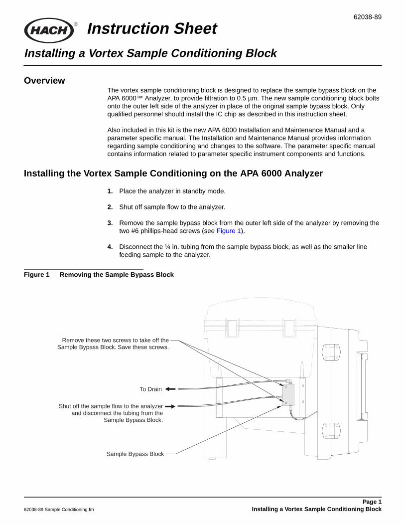
3. Remove the sample bypass block from the outer left side of the analyzer by removing thetwo #6 phillips-head screws (see Figure 1).
4. Disconnect the ¼ in. tubing from the sample bypass block, as well as the smaller linefeeding sample to the analyzer.
Figure 1 Removing the Sample Bypass Block
Remove these two screws to take off the. Save these screws.Sample Bypass Block
Sample Bypass Block
Shut off the sample flow to the analyzerand disconnect the tubing from the
Sample Bypass Block.
To Drain
Page 1stalling a Vortex Sample Conditioning Block
Installing a Vortex Sample Conditioning Block
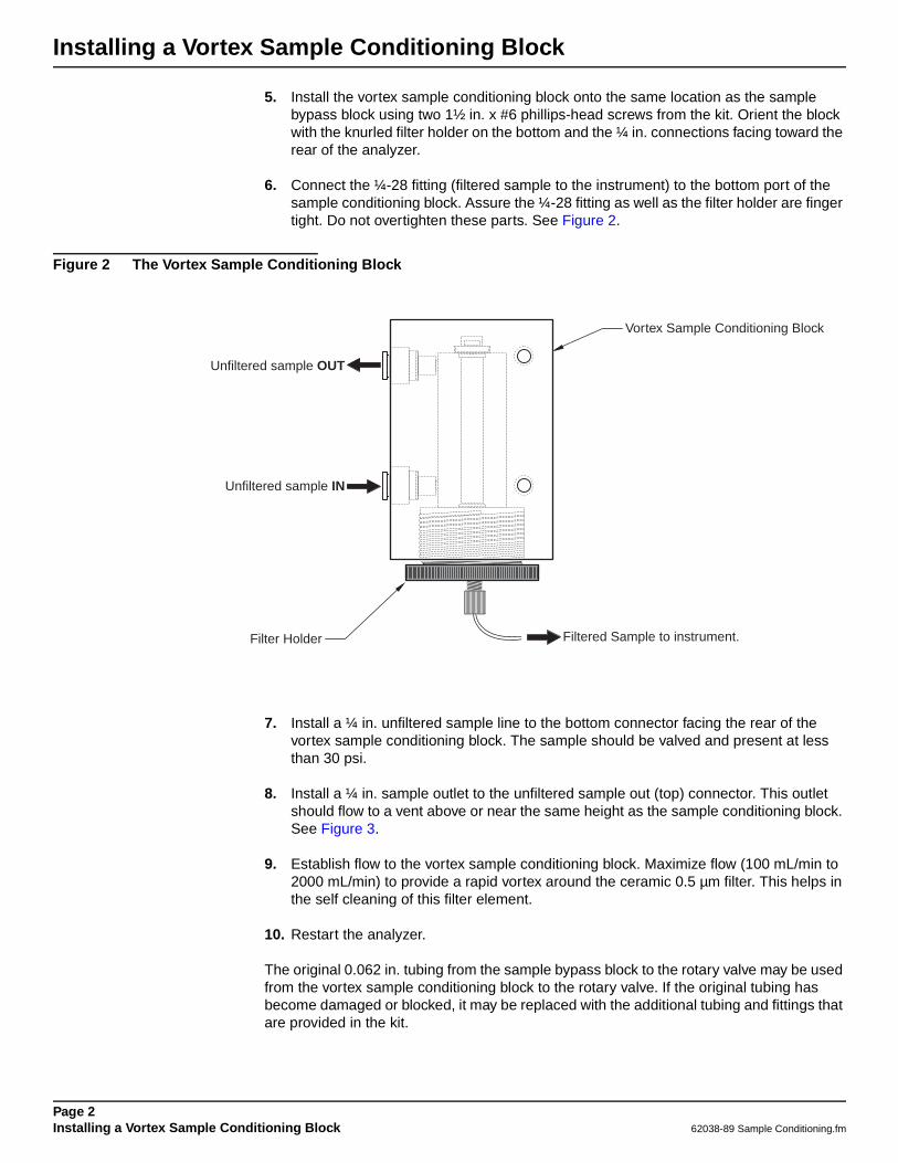
5. Install the vortex sample conditioning block onto the same location as the samplebypass block using two 1½ in. x #6 phillips-head screws from the kit. Orient the blockwith the knurled filter holder on the bottom and the ¼ in. connections facing toward therear of the analyzer.
6. Connect the ¼-28 fitting (filtered sample to the instrument) to the bottom port of thesample conditioning block. Assure the ¼-28 fitting as well as the filter holder are fingertight. Do not overtighten these parts. See Figure 2.
Figure 2 The Vortex Sample Conditioning Block
7. Install a ¼ in. unfiltered sample line to the bottom connector facing the rear of thevortex sample conditioning block. The sample should be valved and present at lessthan 30 psi.
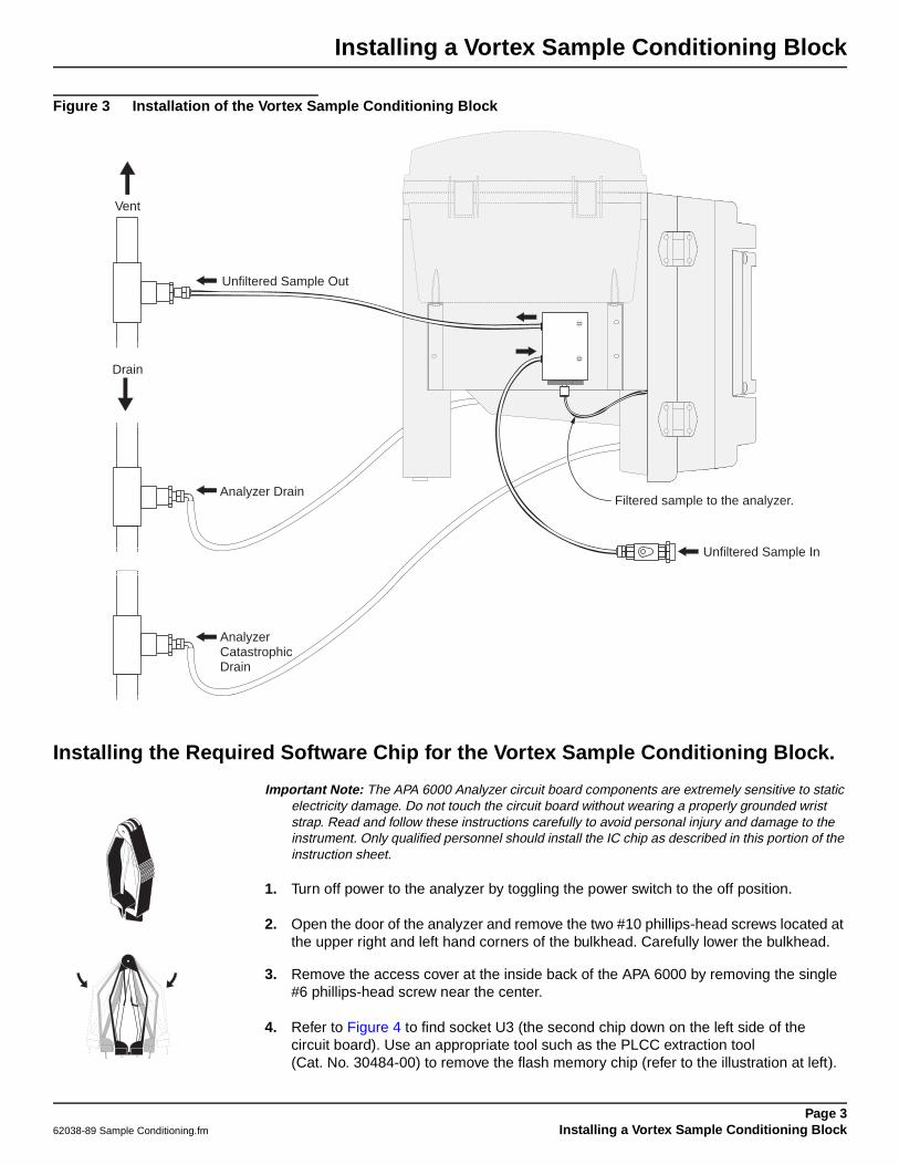
8. Install a ¼ in. sample outlet to the unfiltered sample out (top) connector. This outletshould flow to a vent above or near the same height as the sample conditioning block.See Figure 3.
9. Establish flow to the vortex sample conditioning block. Maximize flow (100 mL/min to2000 mL/min) to provide a rapid vortex around the ceramic 0.5 µm filter. This helps inthe self cleaning of this filter element.
10. Restart the analyzer.
The original 0.062 in. tubing from the sample bypass block to the rotary valve may be usedfrom the vortex sample conditioning block to the rotary valve. If the original tubing hasbecome damaged or blocked, it may be replaced with the additional tubing and fittings thatare provided in the kit.
Unfiltered sample IN
Unfiltered sample OUT
Filtered Sample to instrument.Filter Holder
Vortex Sample Conditioning Block
Page 2Installing a Vortex Sample Conditioning Block 62038-89 Sample Conditioning.fm
Installing a Vortex Sample Conditioning Block
Figure 3 Installation of the Vortex Sample Conditioning Block
Installing the Required Software Chip for the Vortex Sample Conditioning Block.
Important Note: The APA 6000 Analyzer circuit board components are extremely sensitive to staticelectricity damage. Do not touch the circuit board without wearing a properly grounded wriststrap. Read and follow these instructions carefully to avoid personal injury and damage to theinstrument. Only qualified personnel should install the IC chip as described in this portion of theinstruction sheet.
1. Turn off power to the analyzer by toggling the power switch to the off position.
2. Open the door of the analyzer and remove the two #10 phillips-head screws located atthe upper right and left hand corners of the bulkhead. Carefully lower the bulkhead.
3. Remove the access cover at the inside back of the APA 6000 by removing the single#6 phillips-head screw near the center.
4. Refer to Figure 4 to find socket U3 (the second chip down on the left side of thecircuit board). Use an appropriate tool such as the PLCC extraction tool(Cat. No. 30484-00) to remove the flash memory chip (refer to the illustration at left).
Unfiltered Sample In
Filtered sample to the analyzer.
Drain
Vent
Analyzer Drain
Unfiltered Sample Out
AnalyzerCatastrophicDrain
Page 362038-89 Sample Conditioning.fm Installing a Vortex Sample Conditioning Block

Installing a Vortex Sample Conditioning Block
Remove the memory chip from the socket by placing the metal teeth of the extractiontool in the slotted corners of the socket. Gently squeeze the extraction tool to closearound the memory chip. As you squeeze, the teeth of the extraction tool will pull thememory chip from the socket.
5. Carefully install the new flash memory chip in socket U3 with the proper orientation.Orient the memory chip so the angled corner of the chip aligns with the angled cornerof the socket. Press the memory chip firmly in place until it is seated in the socket.
6. Replace the cover and bulkhead. Restore power and begin operation.
Figure 4 IC Chip Location
HACH COMPANYWORLD HEADQUARTERSTelephone: (970) 669-3050FAX: (970) 669-2932
FOR TECHNICAL ASSISTANCE, PRICE INFORMATION AND ORDERING:Call 800-227-4224
Contact the HACH office or distributor serving you.www.hach.com [email protected]
In the U.S.A. –Outside the U.S.A. –On the Worldwide Web – ; E-mail –
toll-free
© Hach Company, 2001. All rights reserved. Printed in the U.S.A. dn/dp 05/01 1ed