
Instruction Manual ZWS-BP Series I n s t r u ct i on Ma … · temperature present and you ... / A...
12
A252-04-01C TDK-Lambda ZWS-BP Series Instruction Manual ZWS-BP Series Instruction Manual BEFORE USING THE POWER SUPPLY UNIT Be sure to read this instruction manual thoroughly before using this product. Pay attention to all cautions and warnings before using this product. Incorrect usage could lead to an electrical shock, damage to the unit or a fire hazard. DANGER Never use this product in locations where flammable gas or ignitable substances are present. There are risks of igniting these substances and exploding by an arcing. WARNING · Do not touch this product or its internal components while circuit is live, or shortly after shutdown. There may be high voltage or high temperature present and you may receive an electric shock or burn. · While this product is operating, keep your hands and face away from it as you may be injured by an unexpected situation. · Do not make unauthorized changes to this product, otherwise you may receive an electric shock and void your warranty. · Do not drop or insert anything into this product. It might cause a failure, fire and electric shock. · Do not use this product under unusual condition such as emission of smoke or abnormal smell and sound etc. It might lead to fire and electric shock. In such cases, please contact us. Do not attempt repair by yourself, as it is dangerous for the user. · Do not operate these products in the presence of condensation. It might lead fire and electric shock. CAUTION · This power supply is designed and manufactured for use within an end product such that it is accessible to SERVICE ENGINEERS only. · Confirm connections to input/output terminals are correct as indicated in the instruction manual before switching on. · Input voltage, Output current, Output power, ambient temperature and ambient humidity should be kept within specifications, otherwise the product will be damaged. · Do not operate and store this product in an environment where condensation might occur. In such case, waterproof treatment is necessary. · Do not use this product in environment with a strong electromagnetic field, corrosive gas or conductive substances. · For applications, which require very high reliability (Nuclear related equipment, medical equipment, traffic control equipment, etc.), it is necessary to provide a fail-safe mechanism in the end equipment. · Do not inject abnormal voltages into the output of this product. The injection of reverse voltage or over voltage exceeding nominal output voltage into the output terminal or signal terminal might cause damage to internal components. · Never operate the product under over current or short-circuit conditions, or outside its specified Input Voltage Range. Insulation failure, smoking, burning or other damage may occur. · This product contains a printed circuit board utilizing surface mounted devices. PCB stress such as bending, twisting etc. could cause damage. Therefore, please handle with care. · When handling this product, hold the board edge and take care not to touch the component side. When installing this product in apparatus or equipment, mount it on spacers. · The outputs of this product may, under fault conditions, exceed SELV voltage limits. Therefore the outputs must be earthed in the end equipment to maintain SELV. If the outputs are not earthed, they must be considered hazardous and must not be made user accessible. · This product has used Power Thermistor to protect the circuit from Inrush Current. Frequent repetition of input might cause damage to internal components because of generating surge current. · Breaking of internal fuse is considered internal failure. In such cases, please contact us. · The output of this product is considered to be a hazardous energy level (The voltage is 2V or more and the power is 240VA or more). It must not be made accessible to users. Protection must be provided for Service Engineers against indirect contact with the output terminals and/or to prevent tools being dropped across them. While working on this product, the AC input power must be switched off and the input and output voltage should be zero. · The information in this document is subject to change without prior notice. Please refer to the latest version of the data sheet, etc., for the most up-to date specifications of the product. · No part of this document may be copied or reproduced in any form without prior written consent of TDK-Lambda. Note: CE MARKING CE Marking, when applied to a product covered by this handbook, indicates compliance with the low voltage directive.
Transcript of Instruction Manual ZWS-BP Series I n s t r u ct i on Ma … · temperature present and you ... / A...

A252-04-01C
TDK-Lambda ZWS-BP Series Instruction Manual
ZWS-BP Series
Instruction Manual
BEFORE USING THE POWER SUPPLY UNIT Be sure to read this instruction manual thoroughly before using this product. Pay attention to all cautions and warnings before using this product. Incorrect usage could lead to an electrical shock, damage to the unit or a fire hazard.
DANGER Never use this product in locations where flammable gas or ignitable substances are present. There are risks of igniting these substances and exploding by an arcing.
WARNING · Do not touch this product or its internal components while circuit is live, or shortly after shutdown. There may be high voltage or high
temperature present and you may receive an electric shock or burn. · While this product is operating, keep your hands and face away from it as you may be injured by an unexpected situation. · Do not make unauthorized changes to this product, otherwise you may receive an electric shock and void your warranty. · Do not drop or insert anything into this product. It might cause a failure, fire and electric shock. · Do not use this product under unusual condition such as emission of smoke or abnormal smell and sound etc. It might lead to fire and electric
shock. In such cases, please contact us. Do not attempt repair by yourself, as it is dangerous for the user. · Do not operate these products in the presence of condensation. It might lead fire and electric shock.
CAUTION · This power supply is designed and manufactured for use within an end product such that it is accessible to SERVICE ENGINEERS only. · Confirm connections to input/output terminals are correct as indicated in the instruction manual before switching on. · Input voltage, Output current, Output power, ambient temperature and ambient humidity should be kept within specifications, otherwise the
product will be damaged. · Do not operate and store this product in an environment where condensation might occur. In such case, waterproof treatment is necessary. · Do not use this product in environment with a strong electromagnetic field, corrosive gas or conductive substances. · For applications, which require very high reliability (Nuclear related equipment, medical equipment, traffic control equipment, etc.), it is
necessary to provide a fail-safe mechanism in the end equipment. · Do not inject abnormal voltages into the output of this product. The injection of reverse voltage or over voltage exceeding nominal output
voltage into the output terminal or signal terminal might cause damage to internal components. · Never operate the product under over current or short-circuit conditions, or outside its specified Input Voltage Range. Insulation failure,
smoking, burning or other damage may occur. · This product contains a printed circuit board utilizing surface mounted devices. PCB stress such as bending, twisting etc. could cause damage.
Therefore, please handle with care. · When handling this product, hold the board edge and take care not to touch the component side. When installing this product in apparatus or
equipment, mount it on spacers. · The outputs of this product may, under fault conditions, exceed SELV voltage limits. Therefore the outputs must be earthed in the end
equipment to maintain SELV. If the outputs are not earthed, they must be considered hazardous and must not be made user accessible. · This product has used Power Thermistor to protect the circuit from Inrush Current. Frequent repetition of input might cause damage to internal
components because of generating surge current. · Breaking of internal fuse is considered internal failure. In such cases, please contact us. · The output of this product is considered to be a hazardous energy level (The voltage is 2V or more and the power is 240VA or more). It must not be made
accessible to users. Protection must be provided for Service Engineers against indirect contact with the output terminals and/or to prevent tools being dropped across them. While working on this product, the AC input power must be switched off and the input and output voltage should be zero.
· The information in this document is subject to change without prior notice. Please refer to the latest version of the data sheet, etc., for the most up-to date specifications of the product.
· No part of this document may be copied or reproduced in any form without prior written consent of TDK-Lambda.
Note: CE MARKING CE Marking, when applied to a product covered by this handbook, indicates compliance with the low voltage directive.

-1-
TDK-Lambda ZWS-BP Series Instruction Manual
1.Model name identification method
ZWS 150 BP – 24 / □
Option Blank : Standard type.
Rated Output Voltage /L : With chassis model./A : With chassis and cover model.
Output Power type /R : With remote ON/OFF control model./T : With terminal model.
Series Name (T : ZWS240BP only)
2.Terminal Explanation ZWS150BP
COMPONENT SIDE
OUTPUT
INPUT①
⑤
②
③
④
⑤
④
⑧
⑥
⑦
⑨
ZWS240BP
COMPONENT SIDE
①
②
③
④
⑤
OUTPUT
INPUT
⑤
④
⑧
⑥
⑦
⑨
⑤ ① L : AC Input terminal Live line (Fuse in line.) ② N : AC Input terminal Neutral line ③ : Earth ( ) Terminal ④ Mounting hole (hole diameter : φ3.5mm)
These holes are connected to terminal of CN1. Must be connected to Chassis (Conductor) of the equipment by metal spacer. The mounting surface of the spacer should be within Maxφ8mm.
⑤ Mounting hole (hole diameter : φ3.5mm) These holes are not connected to terminal of CN1.
⑥ + : + Output Terminal ⑦ - : - Output Terminal ⑧ V.ADJ : Output voltage adjust trimmer. The output voltage rises when a trimmer is turned clockwise. ⑨ ON/OFF Control Terminal (Option model “/R”)
-2-
TDK-Lambda ZWS-BP Series Instruction Manual
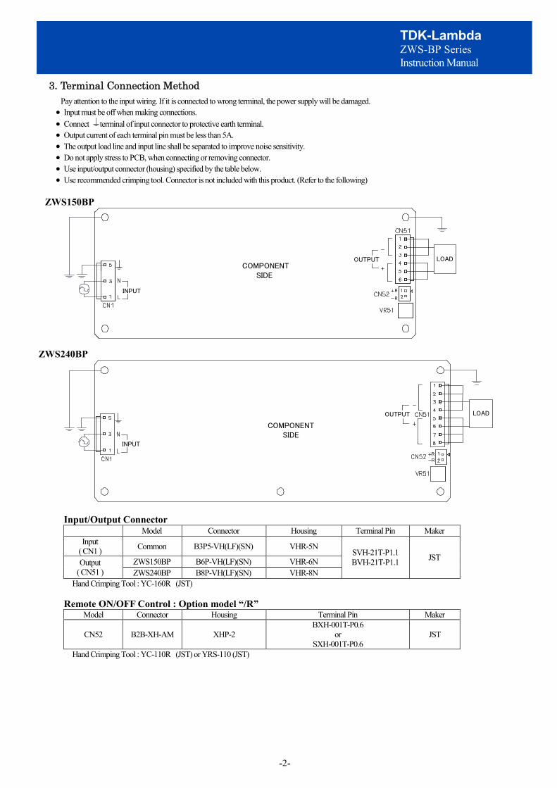
3. Terminal Connection Method Pay attention to the input wiring. If it is connected to wrong terminal, the power supply will be damaged. · Input must be off when making connections. · Connect terminal of input connector to protective earth terminal. · Output current of each terminal pin must be less than 5A. · The output load line and input line shall be separated to improve noise sensitivity. · Do not apply stress to PCB, when connecting or removing connector. · Use input/output connector (housing) specified by the table below. · Use recommended crimping tool. Connector is not included with this product. (Refer to the following)
ZWS150BP
COMPONENT SIDE
OUTPUT
INPUT
LOAD
ZWS240BP
COMPONENT SIDE
OUTPUT
INPUT
LOAD
Input/Output Connector Model Connector Housing Terminal Pin Maker
Input ( CN1 ) Common B3P5-VH(LF)(SN) VHR-5N
SVH-21T-P1.1 BVH-21T-P1.1 JST Output
( CN51 ) ZWS150BP B6P-VH(LF)(SN) VHR-6N ZWS240BP B8P-VH(LF)(SN) VHR-8N
Hand Crimping Tool : YC-160R (JST)
Remote ON/OFF Control : Option model “/R” Model Connector Housing Terminal Pin Maker
CN52 B2B-XH-AM XHP-2 BXH-001T-P0.6
or SXH-001T-P0.6
JST
Hand Crimping Tool : YC-110R (JST) or YRS-110 (JST)

-3-
TDK-Lambda ZWS-BP Series Instruction Manual
4.Explanation of Function and Precautions 4-1. Input Voltage Range
Input voltage range is single phase 85-265VAC(47-63Hz) or 120-370VDC. Input voltage, which is out of specification, might lead unit damage. For cases where conformance to various safeties required, described as 100-240VAC (50-60Hz). Output derating is required for AC input voltage less than 90VAC.
4-2. Output Voltage Range Output voltage is set the rated value at shipment. V.ADJ trimmer (VR51) can adjust the output voltage within the range. Output voltage range is within output voltage variable range. To turn the trimmer clockwise, the output voltage will be increased. Take note when the output voltage is increased excessively, over voltage protection (OVP) function may trigger and voltage will be shut down. Furthermore, when increasing the output voltage reduce the output current so as not to exceed the maximum output power.
4-3. Inrush Current This series equipped Power thermistor to limit the inrush Current. This series are Power thermistor method so that higher current will flow at higher ambient temperature or re-input condition. Please select input switch and fuse carefully with the high temperature and re-input the power condition. The Inrush Current value is under cold start at 25℃ in the specification.
4-4. Delay Shut Down This product have a delay shut down function provided to protect power supply and equipment at the time of the consecutive peak current and output short-circuit. When the product operate peak current and output short-circuit for more than 5 seconds, delay shut down function operates and the output will be shut down. To reset delay shut down, remove the input of power supply for a few minutes, and then re-input. Delay Shut Down Time value is fixed and not to be adjusted externally. Use it about the peak electricity in specifications range. The details see at “5-2. Output Peak Power”
4-5. Over Current Protection (OCP)
ZWS150BP, ZWS240BP : Constant current limit with automatic recovery. OCP function operates when the output current exceeds 201% of average output current of specification. The outputs will be automatically recovered when the overload condition is canceled. Never operate the unit under over current or shorted conditions, which may leads damage or insulation failure. OCP setting is fixed and not to be adjusted externally.
4-6. Over Voltage Protection (OVP) The OVP function (Inverter shut down method, manual reset type) is provided. OVP function operates within 24V: 120% - 140%, 36V - 48V: 115% - 135% of nominal output voltage. When OVP triggers, the output will be shut down. To reset OVP, remove the input of power supply for a few minutes, and then re-input. In addition, the setting value of OVP is fixed and not adjustable. Pay attention not to apply higher voltage externally to the output terminal to avoid unit failure. In case of inductive load, put protective diode in series to the output power line.
4-7. Output Ripple & Noise The standard specification for maximum ripple value is measured according to measurement circuit specified by JEITA-RC9131B. When load lines are longer, ripple will becomes larger. In this case, electrolytic capacitor, film capacitor, etc. might be necessary to use across the load terminal. The output ripple cannot be measure accurately if the probe ground lead of oscilloscope is too long.
LoadC1
150mm
C2
Coaxial Cable1.5m 50Ω
R1
C3
OscilloscopeBandwidth : 100MHz
PowerSupply
+
‐
C1 : 0.1uF Film Cap. C2 : 100uF Electric Cap. C3 : 4700pF Ceramic Cap. R1 : 50Ω
A

-4-
TDK-Lambda ZWS-BP Series Instruction Manual
4-8. Series Operation For series operation, either method (A) or (B) is possible.
ZWS150BP, ZWS240BP
OutputTerminal
OutputTerminal
Load
OutputTerminal
OutputTerminal
Load
Load
(A) (B)Power Supply Power Supply
Note : In case of (A), Never use when one of the unit not operate, which may leads damage.
4-9. Parallel Operation For parallel operation, method (B) is possible. ZWS150BP, ZWS240BP
Load
OutputTerminal
OutputTerminal
Load
OutputTerminal
OutputTerminal
(B) To use as Back-up Power Supply 1. Adjust the output voltage of each power supply to be the same. 2. Set power supply output voltage higher by the forward voltage drop (Vf) of diode. Use within the specification for output voltage and output power.
(A) To increase the output current is not possible.
Power Supply
Power Supply
0 4-10. Isolation Test
Isolation resistance between Output - is more than 100MΩat 500VDC. For safety operation, voltage setting of DC isolation tester must be done before the test. Ensure that the unit is fully discharged after the test.
Output - : 500VDC More than 100MΩ
ZWS150BP, ZWS240BP ZWS150BP/R, ZWS240BP/R
AC(L) AC(N) +
_
Isolation Tester
AC(L) AC(N) +
_ Isolation Tester +R(CN52)
_R(CN52)
-5-
TDK-Lambda ZWS-BP Series Instruction Manual
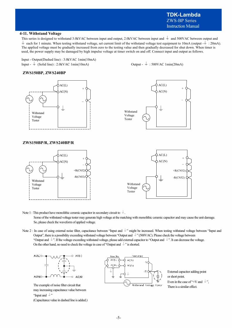
4-11. Withstand Voltage This series is designed to withstand 3.0kVAC between input and output, 2.0kVAC between input and and 500VAC between output and
each for 1 minute. When testing withstand voltage, set current limit of the withstand voltage test equipment to 10mA (output - : 20mA). The applied voltage must be gradually increased from zero to the testing value and then gradually decreased for shut down. When timer is used, the power supply may be damaged by high impulse voltage at timer switch on and off. Connect input and output as follows. Input - Output(Dashed line) : 3.0kVAC 1min(10mA) Input - (Solid line) : 2.0kVAC 1min(10mA) Output - : 500VAC 1min(20mA) ZWS150BP, ZWS240BP
ZWS150BP/R, ZWS240BP/R
Note 1 : This product have monolithic ceramic capacitor in secondary circuit to . Some of the withstand voltage tester may generate high voltage at the matching with monolithic ceramic capacitor and may cause the unit damage. So, please check the waveform of applied voltage.
Note 2 : In case of using external noise filter, capacitance between “Input and ” might be increased. When testing withstand voltage between “Input and
Output”, there is a possibility exceeding withstand voltage between “Output and ” (500VAC). Please check the voltage between “Output and ”. If the voltage exceeding withstand voltage, please add external capacitor to “Output and ”. It can decrease the voltage. On the other hand, no need to check the voltage in case of “Output and ” is shorted.
AC(L)
AC(N) +
_
Withstand Voltage Tester
AC(L)
AC(N) +
_
Withstand Voltage Tester
AC(L)
AC(N)
+ _
Withstand Voltage Tester
+R(CN52)
-R(CN52)
AC(L)
AC(N)
+ _
Withstand Voltage Tester
+R(CN52)
-R(CN52)
The example of noise filter circuit that may increasing capacitance value between “Input and ” (Capacitance value in dashed line is added.)
External capacitor adding point or short point. Even in the case of “+V and ”, There is a similar effect.

-6-
TDK-Lambda ZWS-BP Series Instruction Manual
4-12. Remote ON/OFF Control (Option model “/R”) Remote ON/OFF control (CN52) function is available as option. ( /R). Using this function allows the user to turn the output on and off without having to turn the AC input on and off. It is controlled by the voltage applied to +R and –R. This circuit is in the Secondary (output) side of the power supply unit. Do not connect in the Primary (input) side. And this circuit is isolated from the Secondary (output). The standby power in control OFF is 100VAC input: 0.15W(typ), 200VAC input: 0.5W(typ). (but the loss of the outside circuit to apply does not include it.)
E
Power Supply
1kΩ
+R
-R
SW
R
R : External resistanceE : External voltage level
+R & -R terminal condition
SW ON (Higher than 4.5V)
SW OFF (Lower than 0.8V)
Output Condition
ON
OFF
External voltage level: E
4.5 - 12.5VDC
12.5 - 24.5VDC
External resistance : R
No required
1.5kΩ

-7-
TDK-Lambda ZWS-BP Series Instruction Manual
T
Wp Wm
t 0(W)
T
Wp Wm
t 0(W) a(W)
5.Mounting Directions 5-1. Mounting Directions.
Recommended standard mounting method is (A). Method (B)-(F) are also possible. From an mounting method and power supply ambient temperature, use the output derating of the power supply in specifications value of standard. The details see at “5-3. Output Derating”
CN1 (INPUT)
CN1
CN1 CN1
(A) Standard Mounting
(B) (C) (D) (E) (F)FIN
CN1
FINCN1
5-2. Output Peak Power This product must be use to satisfy (a) and (b). Allowable peak output operating time is less than 5sec. When the product operate peak power for more than 5 sec, the delay shut down function operates and the output will shut down. Peak output power and average output power use less than specification. Peak output power is limited depending on Duty. The details see at (b). The product might be damage to use beyond the limits of (a) and (b). When using pulse load, a noise may be heard from power supply unit. Please evaluate and check before using.
(a) Expression of relations
formula about Duty
(%)100´T
=tDuty
formula about average output power
T´
=³tWpWmWavg ( ) aaWpWmWavg +
T´-
=³t
Wp : Peak output power ( W ) τ : Pulse width of peak output power ( sec ) Wavg : Average output power of Specification ( W ) T : Period ( sec )Wm : Average output power ( W ) Duty : The duty is pulse width of peak output
power of one period(%)
(b) Peak output power vs Duty
ZWS150BP ZWS240BP
0150
Peak output power (W)
Dut
y(%
)
510152025303540
180 2100240
Peak output power (W)
Dut
y(%
)
510152025303540
300 360 420 480300
4545
240 270 330

-8-
TDK-Lambda ZWS-BP Series Instruction Manual
5-3. Output Derating The following input voltage derating curve assumes average output load is 100%. (Peak power dose not have the derating.)
■CONVECTION COOLING
ZWS150BP
Mounting (A)Mounting (B),(C),(E)Mounting (D),(F)
Ta(°C)
-10 - +30+40+50+60+70
Average Load (%)Mounting(A) Mounting(B),(C),(E) Mounting(D),(F)
100100 80100 8075 4050 40
10060
6020Ta (°C)
Ave
rage
Loa
d(%
)
0
20
40
60
80
100
120
-10 0 10 20 30 40 50 60 70 80
ZWS240BP
Mounting (A)Mounting (B),(C)Mounting (E)
Ta(°C)
-10 - +20+30+40+50+60
Average Load (%)Mounting(A)
100
Ta (°C)
Ave
rge
Load
(%)
0
20
40
60
80
100
120
-10 0 10 20 30 40 50 60 70 80
Mounting(B),(C) Mounting(E) Mounting(D),(F)
1001006530
100 78 6477 55 465330
3210
2810+70
100 100 100 82
Mounting (D),(F)
■FORCED AIR COOLING
ZWS150BP, ZWS240BP
Electrolytic capacitor allowable Max temparatureMounting (A) - (F)
Mounting(A) - (F)
ZWS150BP
C7Model
Allowable Max temparature
ZWS240BP
85°C
75°C
C52
75°C
75°C
Ta(°C)
-10 - +60+70
Average Load (%)
10070
80
100
120
80
60
40
20
0-10 0 20 40 5010 30 60 70
Ave
rage
Loa
d (%
)
Ta (°C)
The entire component must be cooled. The maximum temperature of the electrolytic capacitor C7 and C52 must keep lower than “Electrolytic capacitor allowable Max temperature” in the above table. As reference, set wind velocity at 0.7m/s or 1.5m/s.At the time of a forced air cooling, average load varies according to the wind velocity. Please confirm specifications, and be careful. ZWS150BP ZWS240BP
CN1
C52
(INPUT)
C7
CN1(INPUT)
C7
C52
■Average load (FORCED AIR COOLING)
Model 0.7m/s 1.5m/s
ZWS150BP 150W 200W
ZWS240BP 240W 300W
Set wind velocity

-9-
TDK-Lambda ZWS-BP Series Instruction Manual
5-4. Derating curve depending on input voltage
Input voltage (VAC)
Ave
rage
Loa
d(%
)
80
85 90
100
The following input voltage derating curve assumes average output load is 100%.(Peak power dose not have the derating.)
5-5. Mounting Method
Insert the spacer (Maxφ8) of height more than 8mm to lift the unit. And use all mounting holes A for the unit installation. The vibration spec is specified under this mounting condition. Please use mounting hole B as needed. Vibratility-resistant improves.
■Mounting Holes size
ZWS150BP ZWS240BP 4 holesφ3.5mm. 5 holesφ3.5mm.
A AA
AAA
A
AB
CN1 (Input) CN1 (Input)
Height more than8mm spacer
Height more than8mm spacer
Allowable area by metal pieces (Solder side) is the hatched area. Refer to figure below
ZWS150BP ZWS240BP
9mm
9mm
9mm
9mm 9mm9mm
9mm
9mm
9mm
9mm
9mm
9mm 9mm9mm
9mm
9mm
9mm9mm

-10-
TDK-Lambda ZWS-BP Series Instruction Manual
■Condition to meet Isolation & Withstand Voltage standard.
More than 8mm
COMPONENT SIDE
PCB
More than 4mm
Keep 4mm space from the surfaces and sides of PCB. Especially, 8mm space is necessary from the solder surface.If the space is not enough, the specification of isolation and withstand will not be satisfied.Take the space in the power supply surroundings and the upper area of components to keep enough for convection cooling.
More than 4mm
More than 4mm
More than 4mm
More than 4mm
■
should be connected to the protective earth terminal of the equipment. Also 2 mounting holes are should be connected to the Chassis (Conductor) by metal spacer. If not, the conducted noise, radiation noise and output noise will increase.
6. Wiring Method (1) The output load line and input line shall be separated each other and twisted individually to improve noise. (2) Use all lines as thick and short as possible to made lower impedance. (3) Noise can be reduced by attaching a capacitor to the load terminals. (4) For safety and EMI considerations, connect between terminal of input connector and protective earth terminal firmly.
7. External Fuse Rating Refer to the following fuse rating when selecting the external fuses that are to be used on input line. Surge current flows when line turns on. Have to use slow-blow or time-lag type fuse, not fast-blow fuse. Fuse rating is considered by in-rush current value at line turn-on. Do not select the fuse according to input current (RMS.) values under the actual load condition
ZWS150BP : 6.3A ZWS240BP : 10A
8. Before concluding that the unit is at fault (1) Check if the rated input voltage is connected. (2) Check if the wiring of input and output is correct. (3) Check if the wire thickness is enough. (4) Check if the output current and output wattage dose not over specification. (5) Check if the output voltage control (V.ADJ) is properly adjusted. OVP might be triggered and output is shut down. (6) Audible noise can be heard when input voltage waveform is not sinusoidal wave. (7) Audible noise can be heard daring Dynamic-Load operation.
EarthTerminal
Protective
N L
+-
Wire Input
Chassis (Conductor)
Output
Metal spacers

-11-
TDK-Lambda ZWS-BP Series Instruction Manual
9. Warranty Period Warranty Period applies for Mounting Method (A). However, for forced air cooling, mounting method is not specified. For damages occurring at normal operation within this warranty period, repair is free of charge. For other mounting methods, please inquire to TDK-Lambda. ■CONVECTION COOLING ■FORCED AIR COOLING
ZWS150BP, ZWS240BP ZWS150BP, ZWS240BP
Warranted for a period of 5years.
Mounting(A)
Ta (℃)
Mounting(A)-(F)100
80
50 60
Load
(%)
100
Ta (℃)
Load
(%)
80
40 50Warranted for a period of 3years.
Following cases are not covered by warranty.
(1) Improper usage like dropping products, applying shock and defects from operation exceeding specification of the units. (2) Defects resulting from natural disaster (fire, flood etc). (3) Unauthorized modifications or repair by the buyers’ defects not cause by our company.


