INSTRUCTION MANUAL - Welcome To Lectrosonics.com · Essential Setup Steps 1) Install receiver...
28
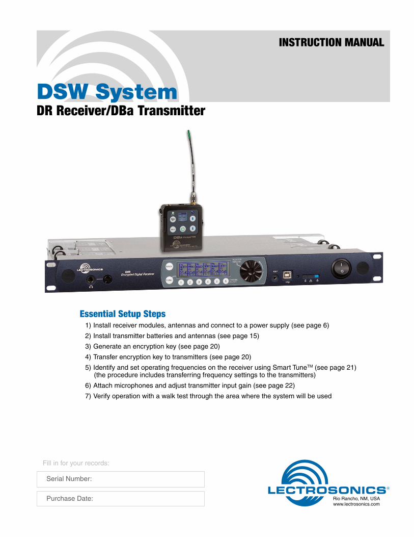
DSW System DR Receiver/DBa Transmitter INSTRUCTION MANUAL Rio Rancho, NM, USA www.lectrosonics.com Fill in for your records: Serial Number: Purchase Date: Essential Setup Steps 1) Install receiver modules, antennas and connect to a power supply (see page 6) 2) Install transmitter batteries and antennas (see page 15) 3) Generate an encryption key (see page 20) 4) Transfer encryption key to transmitters (see page 20) 5) Identify and set operating frequencies on the receiver using Smart Tune TM (see page 21) (the procedure includes transferring frequency settings to the transmitters) 6) Attach microphones and adjust transmitter input gain (see page 22) 7) Verify operation with a walk test through the area where the system will be used
Transcript of INSTRUCTION MANUAL - Welcome To Lectrosonics.com · Essential Setup Steps 1) Install receiver...
DSW SystemDR Receiver/DBa Transmitter
INSTRUCTION MANUAL
Rio Rancho, NM, USAwww.lectrosonics.com
Fill in for your records:
Serial Number:
Purchase Date:
Essential Setup Steps1) Install receiver modules, antennas and connect to a power supply (see page 6)
2) Install transmitter batteries and antennas (see page 15)
3) Generate an encryption key (see page 20)
4) Transfer encryption key to transmitters (see page 20)
5) Identify and set operating frequencies on the receiver using Smart TuneTM (see page 21) (the procedure includes transferring frequency settings to the transmitters)
6) Attach microphones and adjust transmitter input gain (see page 22)
7) Verify operation with a walk test through the area where the system will be used
DSW Digital Wireless System
LECTROSONICS, INC.2
FCC NoticeFor DR Receiver
NOTE: This equipment has been tested and found to comply with the limits for a Class B digital device, pursuant to Part 15 of the FCC Rules. These limits are designed to provide reasonable protection against harmful interference in a residential installation. The equipment generates, uses and can radiate radio frequency energy and, if not installed and used in accordance with the instructions, may cause harmful interference to radio communications. However, there is no guarantee that interference will not occur in a particular installation. If this equipment does cause harmful interference to radio or television reception, which can be determined by turning the equipment off and on, the user is encouraged to try to correct the interference by one or more of the following measures:
• Reorient or relocate the receiving antenna
• Increase the separation between the equipment and receiver
• Connect the equipment into an outlet on a circuit different from that which the receiver is connected
• Consult the dealer or an experienced radio/TV tech-nician for help
Changes or modifications to this equipment not ex-pressly approved by Lectrosonics, Inc. could void the user’s authority to operate it.
DR Receiver Industry Canada Compliance: CAN RSS-Gen/CNR-Gen
For DBa Transmitter
Consumer Alert for US Users - FCC Order DA 10-92Most users do not need a license to operate this wireless microphone system. Nevertheless, operating this micro-phone system without a license is subject to certain restrictions: the system may not cause harmful interference; it must operate at a low power level (not in excess of 50 milliwatts); and it has no protection from interference received from any other device. Purchasers should also be aware that the FCC is currently evaluating use of wireless mi-crophone systems, and these rules are subject to change. For more information, call the FCC at 1-888- CALL-FCC (TTY: 1-888-TELL-FCC) or visit the FCC’s wireless microphone website at www.fcc.gov/cgb/wirelessmicrophones. To operate wireless microphone systems at power greater than 50mW, you must qualify as a Part 74 user and be licensed. If you qualify and wish to apply for a license go to: http://www.fcc.gov/Forms/Form601/601.html
DSW Digital Wireless System
Rio Rancho, NM 3
IntroductionDSW (Digital Secure Wireless) is designed for no-com-promise applications where performance and security are the highest priority.
A completely new digital architecture was developed for the DSW wireless system. Extended operating range rivals the best analog and Digital Hybrid Wire-less® systems, with remarkable audio quality and only 2.5 ms of latency. The system operates on standard UHF FCC Part 74 frequencies (TV channel band).
256-bit encryption is applied to the transmitted signal stream for security against eavesdropping. The algo-rithm conforms to the AES 256-CTR standard.
DR Modular ReceiverThe DR receiver is a 1RU modular, six-channel design with a host mainframe that contains the DSP, micro-processor, antenna multicoupler and control interface. Receiver modules are installed on either side of the mainframe. No tools are required to remove and install the receiver modules. Each module will tune across a 25.6 MHz range.
Antenna ports on the rear panel accept input from remote antennas. A high quality internal multicoupler distributes the RF signal to the receiver modules and a “loop-thru” output to another mainframe.
For rack mount installations, a kit is available to mount antenna inputs (BNC connectors) on the receiver front panel using a coaxial cable routed through the receiver chassis to the rear panel connections.
DBa Belt Pack TransmitterThe DBa belt pack transmitter is encased in a solid machined aluminum housing with a membrane switch keypad and backlit LCD interface. The servo bias input circuitry will work with a wide variety of microphones and line level sources, Input gain is adjustable over a wide range in 1 dB steps to optimize the signal to noise ratio and dynamics of the audio.
The transmitter tunes across the entire frequency range of the DSW system, from 470.100 MHz to 607.900 and 614.100 to 691.175 MHz.
Table of ContentsEssential Setup Steps ........................................................ 1
FCC Notice ........................................................................... 2Receiver Front Panel ........................................................... 4
Headphone output ............................................................. 4LCD and control Interface .................................................. 4Encryption key and settings transfer port ........................... 4USB Port ............................................................................ 4Comm LED ........................................................................ 4Alert LED ........................................................................... 4Power LED ......................................................................... 4
Receiver Rear Panel ............................................................ 5Antenna connections ......................................................... 5Audio Outputs .................................................................... 5Ethernet Port ...................................................................... 5AES Word Clock ................................................................ 5RS-232 Port ....................................................................... 5Antenna Cable Front Panel Pass-thru ................................ 5Power Supply ..................................................................... 5
Hardware Installation .......................................................... 6Receiver Modules .............................................................. 6Antenna Connections ......................................................... 6Audio Output Wiring - Analog ............................................. 7Audio Output Wiring - AES3 Digital .................................... 7Connections for Computer Interface .................................. 7RS-232 Port Pinouts .......................................................... 7Ethernet Port ...................................................................... 7
Receiver LCD Interface ....................................................... 8Navigating the Menus ........................................................ 9Menu Map and Icons ......................................................... 10
Software Installation ........................................................... 13Windows Installation .......................................................... 13
Using the Walk Test Recorder ............................................. 14Mac Installation .................................................................. 14
Connecting to a Network .................................................... 14Using DHCP for IP Address Assignment ........................... 14
DBa Transmitter ................................................................... 15Features and Functions ..................................................... 15DBa Transmitter LCD Interface .......................................... 15Powering On in Operating Mode ........................................ 16Powering On in Standby Mode .......................................... 16Powering Off ...................................................................... 16Power Menu ....................................................................... 16Navigating Menus .............................................................. 16Adjusting the Input Gain ..................................................... 17Selecting Frequency .......................................................... 17Selecting Programmable Switch Functions........................ 17Selecting the Low Frequency Roll-off ................................ 17Other Menu Items .............................................................. 17DBa Transmitter Menu Map ............................................... 18Copying Transmitter Settings To and From the Receiver ... 19
System Setup ....................................................................... 20Accessories ......................................................................... 24Specifications ...................................................................... 25Service and Repair .............................................................. 26
Returning Units for Repair ................................................. 26
DSW Digital Wireless System
LECTROSONICS, INC.4
Receiver Front Panel
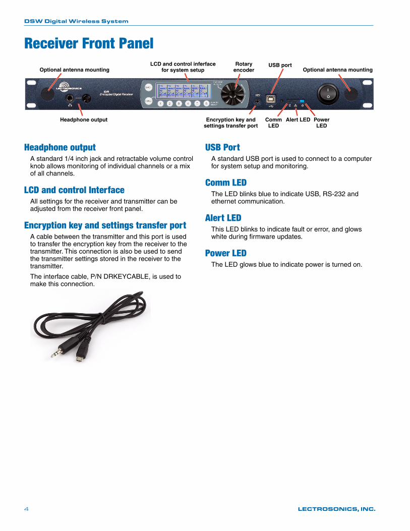
Headphone outputA standard 1/4 inch jack and retractable volume control knob allows monitoring of individual channels or a mix of all channels.
LCD and control InterfaceAll settings for the receiver and transmitter can be adjusted from the receiver front panel.
Encryption key and settings transfer portA cable between the transmitter and this port is used to transfer the encryption key from the receiver to the transmitter. This connection is also be used to send the transmitter settings stored in the receiver to the transmitter.
The interface cable, P/N DRKEYCABLE, is used to make this connection.
USB PortA standard USB port is used to connect to a computer for system setup and monitoring.
Comm LEDThe LED blinks blue to indicate USB, RS-232 and ethernet communication.
Alert LEDThis LED blinks to indicate fault or error, and glows white during firmware updates.
Power LEDThe LED glows blue to indicate power is turned on.
Headphone output
LCD and control inferface for system setup
Encryption key and settings transfer port
USB port
Comm LED
Alert LED Power LED
Rotary encoderOptional antenna mounting Optional antenna mounting
DSW Digital Wireless System
Rio Rancho, NM 5
Receiver Rear Panel
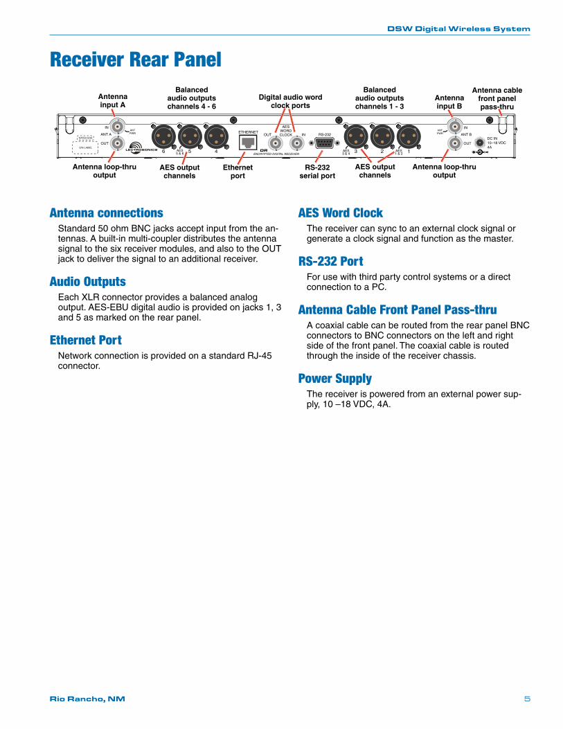
Antenna connectionsStandard 50 ohm BNC jacks accept input from the an-tennas. A built-in multi-coupler distributes the antenna signal to the six receiver modules, and also to the OUT jack to deliver the signal to an additional receiver.
Audio OutputsEach XLR connector provides a balanced analog output. AES-EBU digital audio is provided on jacks 1, 3 and 5 as marked on the rear panel.
Ethernet PortNetwork connection is provided on a standard RJ-45 connector.
AES Word ClockThe receiver can sync to an external clock signal or generate a clock signal and function as the master.
RS-232 PortFor use with third party control systems or a direct connection to a PC.
Antenna Cable Front Panel Pass-thruA coaxial cable can be routed from the rear panel BNC connectors to BNC connectors on the left and right side of the front panel. The coaxial cable is routed through the inside of the receiver chassis.
Power SupplyThe receiver is powered from an external power sup-ply, 10 –18 VDC, 4A.
( ) ( )
AESWORDCLOCK
ANTPWR
AES5 & 6
AES3 & 4
AES1 & 2
ANTPWR
Antenna input A
Antenna input B
Antenna loop-thru output
Antenna loop-thru output
RS-232 serial port
Digital audio word clock ports
Ethernet port
Balanced audio outputs channels 4 - 6
AES output channels
AES output channels
Antenna cable front panel pass-thru
Balanced audio outputs channels 1 - 3
DSW Digital Wireless System
LECTROSONICS, INC.6
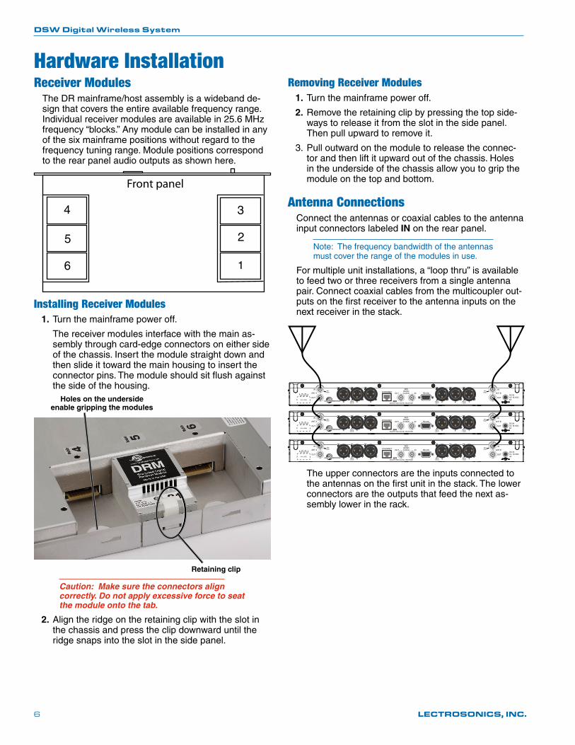
Removing Receiver Modules1. Turn the mainframe power off.
2. Remove the retaining clip by pressing the top side-ways to release it from the slot in the side panel. Then pull upward to remove it.
3. Pull outward on the module to release the connec-tor and then lift it upward out of the chassis. Holes in the underside of the chassis allow you to grip the module on the top and bottom.
Antenna ConnectionsConnect the antennas or coaxial cables to the antenna input connectors labeled IN on the rear panel.
Note: The frequency bandwidth of the antennas must cover the range of the modules in use.
For multiple unit installations, a “loop thru” is available to feed two or three receivers from a single antenna pair. Connect coaxial cables from the multicoupler out-puts on the first receiver to the antenna inputs on the next receiver in the stack.
( ) ( )
AESWORDCLOCK
ANTPWR
AES5 & 6
AES3 & 4
AES1 & 2
ANTPWR
( ) ( )
AESWORDCLOCK
ANTPWR
AES5 & 6
AES3 & 4
AES1 & 2
ANTPWR
( ) ( )
AESWORDCLOCK
ANTPWR
AES5 & 6
AES3 & 4
AES1 & 2
ANTPWR
The upper connectors are the inputs connected to the antennas on the first unit in the stack. The lower connectors are the outputs that feed the next as-sembly lower in the rack.
Hardware InstallationReceiver Modules
The DR mainframe/host assembly is a wideband de-sign that covers the entire available frequency range. Individual receiver modules are available in 25.6 MHz frequency “blocks.” Any module can be installed in any of the six mainframe positions without regard to the frequency tuning range. Module positions correspond to the rear panel audio outputs as shown here.
Front panel
1
2
34
5
6
Installing Receiver Modules1. Turn the mainframe power off.
The receiver modules interface with the main as-sembly through card-edge connectors on either side of the chassis. Insert the module straight down and then slide it toward the main housing to insert the connector pins. The module should sit flush against the side of the housing.
Retaining clip
Holes on the underside enable gripping the modules
Caution: Make sure the connectors align correctly. Do not apply excessive force to seat the module onto the tab.
2. Align the ridge on the retaining clip with the slot in the chassis and press the clip downward until the ridge snaps into the slot in the side panel.
DSW Digital Wireless System
Rio Rancho, NM 7
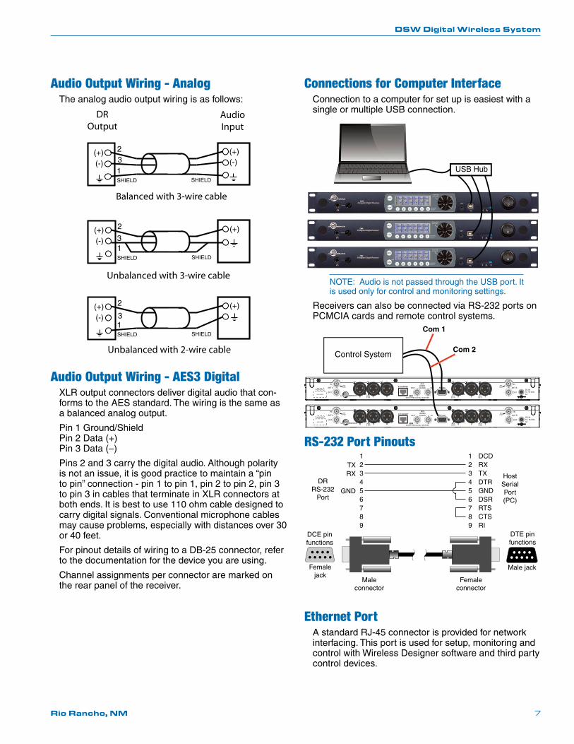
Audio Output Wiring - AnalogThe analog audio output wiring is as follows:
(+)
1(-)
SHIELD SHIELD
(+)(-)
23
(+)
1(-)
SHIELD SHIELD
(+)2
3
(+)
1(-)
SHIELD SHIELD
(+)2
3
DROutput
AudioInput
Balanced with 3-wire cable
Unbalanced with 3-wire cable
Unbalanced with 2-wire cable
Audio Output Wiring - AES3 DigitalXLR output connectors deliver digital audio that con-forms to the AES standard. The wiring is the same as a balanced analog output.
Pin 1 Ground/Shield Pin 2 Data (+) Pin 3 Data (–)
Pins 2 and 3 carry the digital audio. Although polarity is not an issue, it is good practice to maintain a “pin to pin” connection - pin 1 to pin 1, pin 2 to pin 2, pin 3 to pin 3 in cables that terminate in XLR connectors at both ends. It is best to use 110 ohm cable designed to carry digital signals. Conventional microphone cables may cause problems, especially with distances over 30 or 40 feet.
For pinout details of wiring to a DB-25 connector, refer to the documentation for the device you are using.
Channel assignments per connector are marked on the rear panel of the receiver.
Connections for Computer InterfaceConnection to a computer for set up is easiest with a single or multiple USB connection.
USB Hub
NOTE: Audio is not passed through the USB port. It is used only for control and monitoring settings.
Receivers can also be connected via RS-232 ports on PCMCIA cards and remote control systems.
( ) ( )
AESWORDCLOCK
ANTPWR
AES5 & 6
AES3 & 4
AES1 & 2
ANTPWR
( ) ( )
AESWORDCLOCK
ANTPWR
AES5 & 6
AES3 & 4
AES1 & 2
ANTPWR
Control System
Com 1
Com 2
RS-232 Port Pinouts123456789
123456789
DCDRXTXDTRGNDDSRRTSCTSRI
TXRX
GND
Host Serial Port (PC)
DR RS-232
Port
DTE pin functions
Female connector
Male connector
DCE pin functions
Female jack
Male jack
Ethernet PortA standard RJ-45 connector is provided for network interfacing. This port is used for setup, monitoring and control with Wireless Designer software and third party control devices.
DSW Digital Wireless System
LECTROSONICS, INC.8
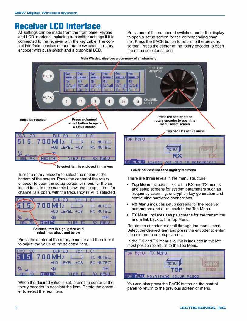
Receiver LCD InterfaceAll settings can be made from the front panel keypad and LCD interface, including transmitter settings if it is connected to the receiver with the key cable. The con-trol interface consists of membrane switches, a rotary encoder with push switch and a graphical LCD.
Press a channel select button to open
a setup screen
Press the center of the rotary encoder to open the
menu select screenSelected receiver
Selected item is enclosed in markers
Turn the rotary encoder to select the option at the bottom of the screen. Press the center of the rotary encoder to open the setup screen or menu for the se-lected item. In the example below, the setup screen for channel 3 is open, with the frequency in MHz selected.
Selected item is highlighted with ruled lines above and below
Press the center of the rotary encoder and then turn it to adjust the value of the selected item.
When the desired value is set, press the center of the rotary encoder to deselect the item. Rotate the encod-er to select the next item.
Press one of the numbered switches under the display to open a setup screen for the corresponding chan-nel. Press the BACK button to return to the previous screen. Press the center of the rotary encoder to open the menu selector screen.
There are three levels in the menu structure:
• Top Menu includes links to the RX and TX menus and setup screens for system parameters such as frequency scanning, encryption key generation and configuring hardware connections.
• RX Menu includes setup screens for the receiver parameters and a link back to the Top Menu.
• TX Menu includes setups screens for the transmitter and a link back to the Top Menu.
Rotate the encoder to scroll through the menu items. Select the desired item and press the encoder to enter the next menu or setup screen.
In the RX and TX menus, a link is included in the left-most position to return to the Top Menu.
You can also press the BACK button on the control panel to return to the previous screen or menu.
Lower bar describes the highlighted menu
Top bar lists active menu
Main Window displays a summary of all channels
DSW Digital Wireless System
Rio Rancho, NM 9
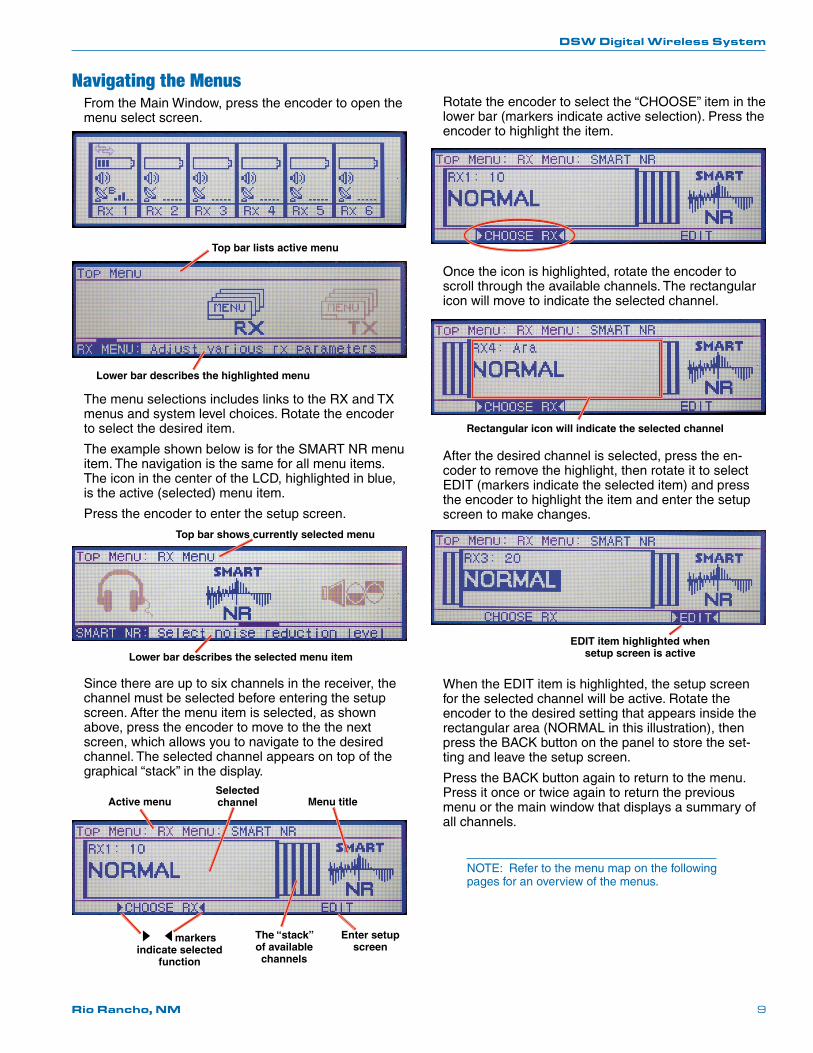
Navigating the MenusFrom the Main Window, press the encoder to open the menu select screen.
Lower bar describes the highlighted menu
Top bar lists active menu
The menu selections includes links to the RX and TX menus and system level choices. Rotate the encoder to select the desired item.
The example shown below is for the SMART NR menu item. The navigation is the same for all menu items. The icon in the center of the LCD, highlighted in blue, is the active (selected) menu item.
Press the encoder to enter the setup screen.
Top bar shows currently selected menu
Lower bar describes the selected menu item
Since there are up to six channels in the receiver, the channel must be selected before entering the setup screen. After the menu item is selected, as shown above, press the encoder to move to the the next screen, which allows you to navigate to the desired channel. The selected channel appears on top of the graphical “stack” in the display.
Active menuSelected channel Menu title
Enter setup screen
markers indicate selected
function
The “stack” of available channels
Rotate the encoder to select the “CHOOSE” item in the lower bar (markers indicate active selection). Press the encoder to highlight the item.
Once the icon is highlighted, rotate the encoder to scroll through the available channels. The rectangular icon will move to indicate the selected channel.
Rectangular icon will indicate the selected channel
After the desired channel is selected, press the en-coder to remove the highlight, then rotate it to select EDIT (markers indicate the selected item) and press the encoder to highlight the item and enter the setup screen to make changes.
EDIT item highlighted when setup screen is active
When the EDIT item is highlighted, the setup screen for the selected channel will be active. Rotate the encoder to the desired setting that appears inside the rectangular area (NORMAL in this illustration), then press the BACK button on the panel to store the set-ting and leave the setup screen.
Press the BACK button again to return to the menu. Press it once or twice again to return the previous menu or the main window that displays a summary of all channels.
NOTE: Refer to the menu map on the following pages for an overview of the menus.
DSW Digital Wireless System
LECTROSONICS, INC.10
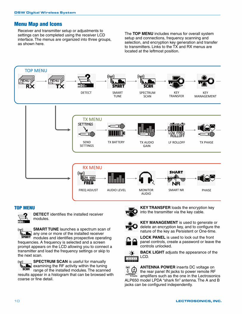
Menu Map and IconsReceiver and transmitter setup or adjustments to settings can be completed using the receiver LCD interface. The menus are organized into three groups, as shown here.
The TOP MENU includes menus for overall system setup and connections, frequency scanning and selection, and encryption key generation and transfer to transmitters. Links to the TX and RX menus are located at the leftmost position.
TOP MENUDETECT identifies the installed receiver modules.
SMART TUNE launches a spectrum scan of any one or more of the installed receiver modules and identifies prospective operating
frequencies. A frequency is selected and a screen prompt appears on the LCD allowing you to connect a transmitter and load the frequency settings or skip to the next scan.
SPECTRUM SCAN is useful for manually examining the RF activity within the tuning range of the installed modules. The scanned
results appear in a histogram that can be browsed with coarse or fine detail.
KEY TRANSFER loads the encryption key into the transmitter via the key cable.
KEY MANAGEMENT is used to generate or delete an encryption key, and to configure the nature of the key as Persistent or One-time.
LOCK PANEL is used to lock out the front panel controls, create a password or leave the controls unlocked.
BACK LIGHT adjusts the appearance of the LCD.
ANTENNA POWER inserts DC voltage on the rear panel IN jacks to power remote RF amplifiers such as the one in the Lectrosonics
ALP650 model LPDA “shark fin” antenna. The A and B jacks can be configured independently.
DETECT SMART TUNE
SPECTRUM SCAN
KEY TRANSFER
KEYMANAGEMENT
SENDSETTINGS
TX BATTERY TX AUDIO GAIN
LF ROLLOFF TX PHASE
FREQ ADJUST AUDIO LEVEL MONITOR AUDIO
SMART NR PHASE
TOP MENU
TX MENU
RX MENU
DSW Digital Wireless System
Rio Rancho, NM 11
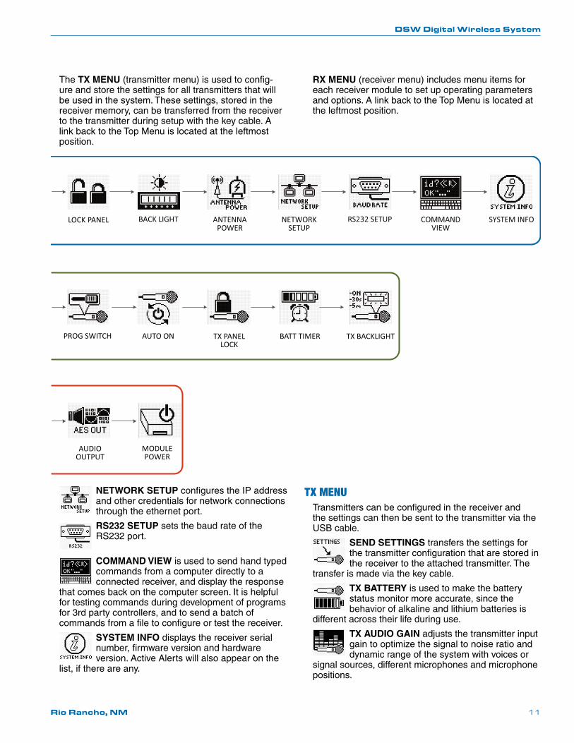
The TX MENU (transmitter menu) is used to config-ure and store the settings for all transmitters that will be used in the system. These settings, stored in the receiver memory, can be transferred from the receiver to the transmitter during setup with the key cable. A link back to the Top Menu is located at the leftmost position.
RX MENU (receiver menu) includes menu items for each receiver module to set up operating parameters and options. A link back to the Top Menu is located at the leftmost position.
NETWORK SETUP configures the IP address and other credentials for network connections through the ethernet port.
RS232 SETUP sets the baud rate of the RS232 port.
COMMAND VIEW is used to send hand typed commands from a computer directly to a connected receiver, and display the response
that comes back on the computer screen. It is helpful for testing commands during development of programs for 3rd party controllers, and to send a batch of commands from a file to configure or test the receiver.
SYSTEM INFO displays the receiver serial number, firmware version and hardware version. Active Alerts will also appear on the
list, if there are any.
TX MENUTransmitters can be configured in the receiver and the settings can then be sent to the transmitter via the USB cable.
SEND SETTINGS transfers the settings for the transmitter configuration that are stored in the receiver to the attached transmitter. The
transfer is made via the key cable.
TX BATTERY is used to make the battery status monitor more accurate, since the behavior of alkaline and lithium batteries is
different across their life during use.
TX AUDIO GAIN adjusts the transmitter input gain to optimize the signal to noise ratio and dynamic range of the system with voices or
signal sources, different microphones and microphone positions.
LOCK PANEL BACK LIGHT ANTENNA POWER
NETWORK SETUP
RS232 SETUP COMMAND VIEW
SYSTEM INFO
PROG SWITCH AUTO ON TX PANEL LOCK
BATT TIMER TX BACKLIGHT
AUDIO OUTPUT
MODULE POWER
DSW Digital Wireless System
LECTROSONICS, INC.12
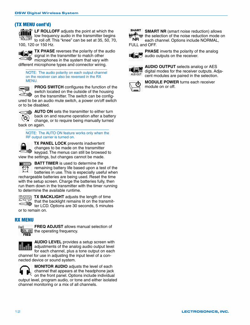
(TX MENU cont’d)LF ROLLOFF adjusts the point at which the low frequency audio in the transmitter begins to roll off. This “knee” can be set at 35, 50, 70,
100, 120 or 150 Hz.
TX PHASE reverses the polarity of the audio signal in the transmitter to match other microphones in the system that vary with
different microphone types and connector wiring.
NOTE: The audio polarity on each output channel on the receiver can also be reversed in the RX MENU.
PROG SWITCH configures the function of the switch located on the outside of the housing on the transmitter. The switch can be config-
ured to be an audio mute switch, a power on/off switch or to be disabled.
AUTO ON sets the transmitter to either turn back on and resume operation after a battery change, or to require being manually turned
back on again.
NOTE: The AUTO ON feature works only when the RF output carrier is turned on.
TX PANEL LOCK prevents inadvertent changes to be made on the transmitter keypad. The menus can still be browsed to
view the settings, but changes cannot be made.
BATT TIMER is used to determine the remaining battery life based upon a test of the batteries in use. This is especially useful when
rechargeable batteries are being used. Reset the time with the setup screen. Charge the batteries fully, then run them down in the transmitter with the timer running to determine the available runtime.
TX BACKLIGHT adjusts the length of time that the backlight remains lit on the transmit-ter LCD. Options are 30 seconds, 5 minutes
or to remain on.
RX MENUFREQ ADJUST allows manual selection of the operating frequency.
AUDIO LEVEL provides a setup screen with adjustments of the analog audio output level for each channel, plus a tone output on each
channel for use in adjusting the input level of a con-nected device or sound system.
MONITOR AUDIO adjusts the level of each channel that appears at the headphone jack on the front panel. Options include individual
output level, program audio, or tone and either isolated channel monitoring or a mix of all channels.
SMART NR (smart noise reduction) allows the selection of the noise reduction mode on each channel. Options include NORMAL,
FULL and OFF.
PHASE inverts the polarity of the analog audio outputs on the receiver.
AUDIO OUTPUT selects analog or AES digital modes for the receiver outputs. Adja-cent modules are paired in the selection.
MODULE POWER turns each receiver module on or off.
DSW Digital Wireless System
Rio Rancho, NM 13
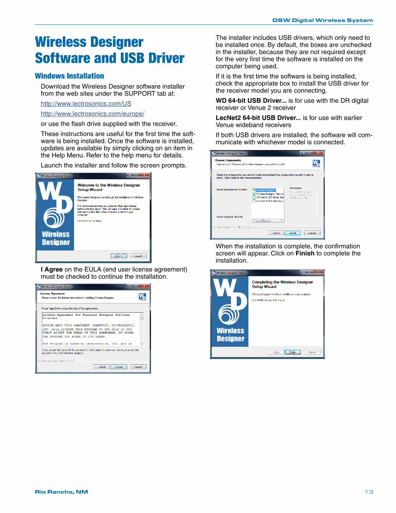
Wireless Designer Software and USB DriverWindows Installation
Download the Wireless Designer software installer from the web sites under the SUPPORT tab at:
http://www.lectrosonics.com/US
http://www.lectrosonics.com/europe/
or use the flash drive supplied with the receiver.
These instructions are useful for the first time the soft-ware is being installed. Once the software is installed, updates are available by simply clicking on an item in the Help Menu. Refer to the help menu for details.
Launch the installer and follow the screen prompts.
I Agree on the EULA (end user license agreement) must be checked to continue the installation.
The installer includes USB drivers, which only need to be installed once. By default, the boxes are unchecked in the installer, because they are not required except for the very first time the software is installed on the computer being used.
If it is the first time the software is being installed, check the appropriate box to install the USB driver for the receiver model you are connecting.
WD 64-bit USB Driver... is for use with the DR digital receiver or Venue 2 receiver
LecNet2 64-bit USB Driver... is for use with earlier Venue wideband receivers
If both USB drivers are installed, the software will com-municate with whichever model is connected.
When the installation is complete, the confirmation screen will appear. Click on Finish to complete the installation.
DSW Digital Wireless System
LECTROSONICS, INC.14
Connecting to a NetworkUsing DHCP for IP Address Assignment
Follow these steps to make a network connection for the receiver:
1) Open Wireless Designer and connect to the receiver via USB.
2) Click on Settings in the left pane. Then click on the Network tab in the lower part of the screen. Inside the dialog box labeled Network Settings, click on the check box labeled DHCP Enable.
3) Close Wireless Designer.
4) Connect the network cable to the Ethernet port on the rear panel.
5) Turn the receiver power off then back on.
6) Launch Wireless Designer again and navigate to Network Settings as described above. The IP address and port number will appear in the dialog box.
7) Close the USB connection and re-connect via network. When the dialog box opens, enter the IP address and the port number noted, then click on Refresh. Click on OK to connect.
Using the Walk Test Recorder
Wireless Designer software provides a very useful utility for system checkout called Walk Test Recorder. With the system running, the person wearing the trans-mitter walks through the area where the wireless will be used and verbally describes their location as they walk. The software provides a scrolling display that re-cords the RF signal level as the walk test is conducted.
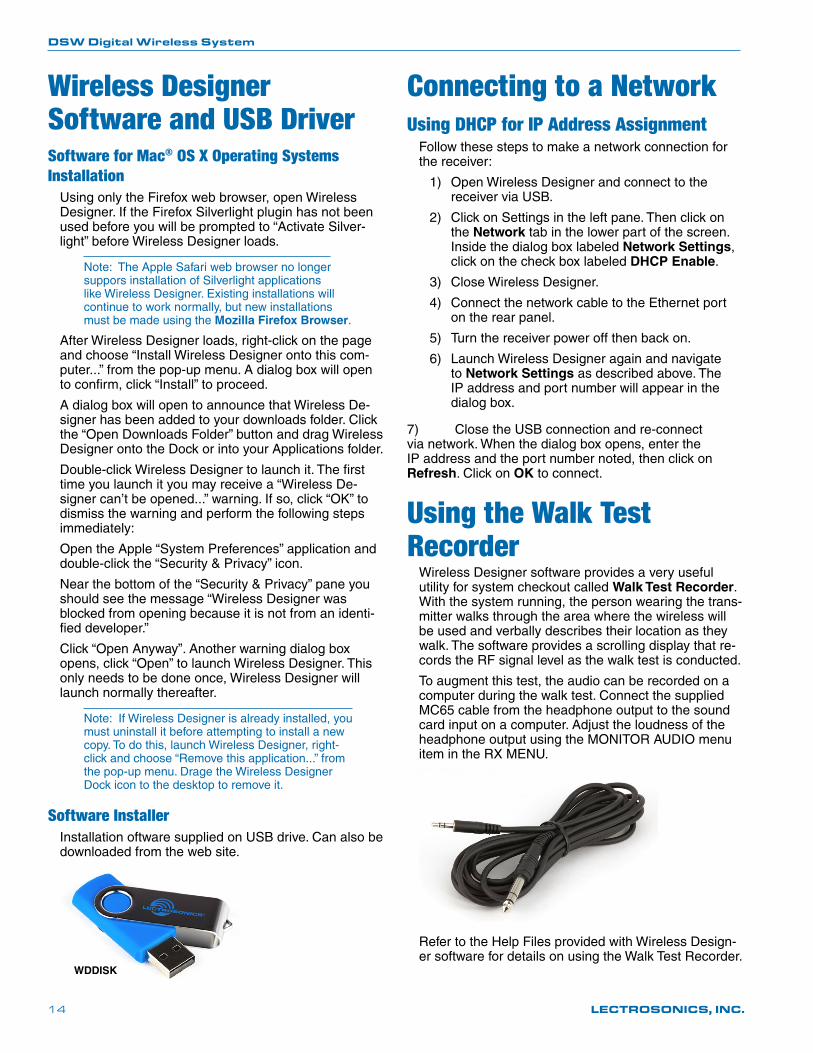
To augment this test, the audio can be recorded on a computer during the walk test. Connect the supplied MC65 cable from the headphone output to the sound card input on a computer. Adjust the loudness of the headphone output using the MONITOR AUDIO menu item in the RX MENU.
Refer to the Help Files provided with Wireless Design-er software for details on using the Walk Test Recorder.
Wireless Designer Software and USB DriverSoftware for Mac® OS X Operating Systems Installation
Using only the Firefox web browser, open Wireless Designer. If the Firefox Silverlight plugin has not been used before you will be prompted to “Activate Silver-light” before Wireless Designer loads.
Note: The Apple Safari web browser no longer suppors installation of Silverlight applications like Wireless Designer. Existing installations will continue to work normally, but new installations must be made using the Mozilla Firefox Browser.
After Wireless Designer loads, right-click on the page and choose “Install Wireless Designer onto this com-puter...” from the pop-up menu. A dialog box will open to confirm, click “Install” to proceed.
A dialog box will open to announce that Wireless De-signer has been added to your downloads folder. Click the “Open Downloads Folder” button and drag Wireless Designer onto the Dock or into your Applications folder.
Double-click Wireless Designer to launch it. The first time you launch it you may receive a “Wireless De-signer can’t be opened...” warning. If so, click “OK” to dismiss the warning and perform the following steps immediately:
Open the Apple “System Preferences” application and double-click the “Security & Privacy” icon.
Near the bottom of the “Security & Privacy” pane you should see the message “Wireless Designer was blocked from opening because it is not from an identi-fied developer.”
Click “Open Anyway”. Another warning dialog box opens, click “Open” to launch Wireless Designer. This only needs to be done once, Wireless Designer will launch normally thereafter.
Note: If Wireless Designer is already installed, you must uninstall it before attempting to install a new copy. To do this, launch Wireless Designer, right-click and choose “Remove this application...” from the pop-up menu. Drage the Wireless Designer Dock icon to the desktop to remove it.
Software InstallerInstallation oftware supplied on USB drive. Can also be downloaded from the web site.
WDDISK
DSW Digital Wireless System
Rio Rancho, NM 15
DBa TransmitterDBa Transmitter LCD Interface
The keypad and LCD interface provides access to set-tings and adjustments.
Steve
494.500-40 -20 0
MUTE
Battery status LED
Key verification LED
Power button
Menu navigation
buttonsReturn to previous screen
The Main Window displays programmable switch function, Standby or Operating mode, operating frequency, audio level and battery status.
Steve
494.500-40 -20 0
MUTE
Frequency (MHz)
RF indicator
Battery status
Programmable switch function
Audio level
Transmitter name
NOTE: The transmitter name that appears on the LCD is created with the software and downloaded to the transmitter with the USB cable connected.
In the Standby Mode the RF indicator icon will blink to indicate that the RF output is turned off.
Steve
494.500-40 -20 0
MUTE
If the programmable switch function is set for MUTE, the Main Window will indicate that the function is enabled. When the switch is turned on, the mute icon appearance will change and the word MUTE will blink at the bottom of the display. The green -10 LED on the top panel will also blink.
Steve
494.500MUTE
<–MUTE–>
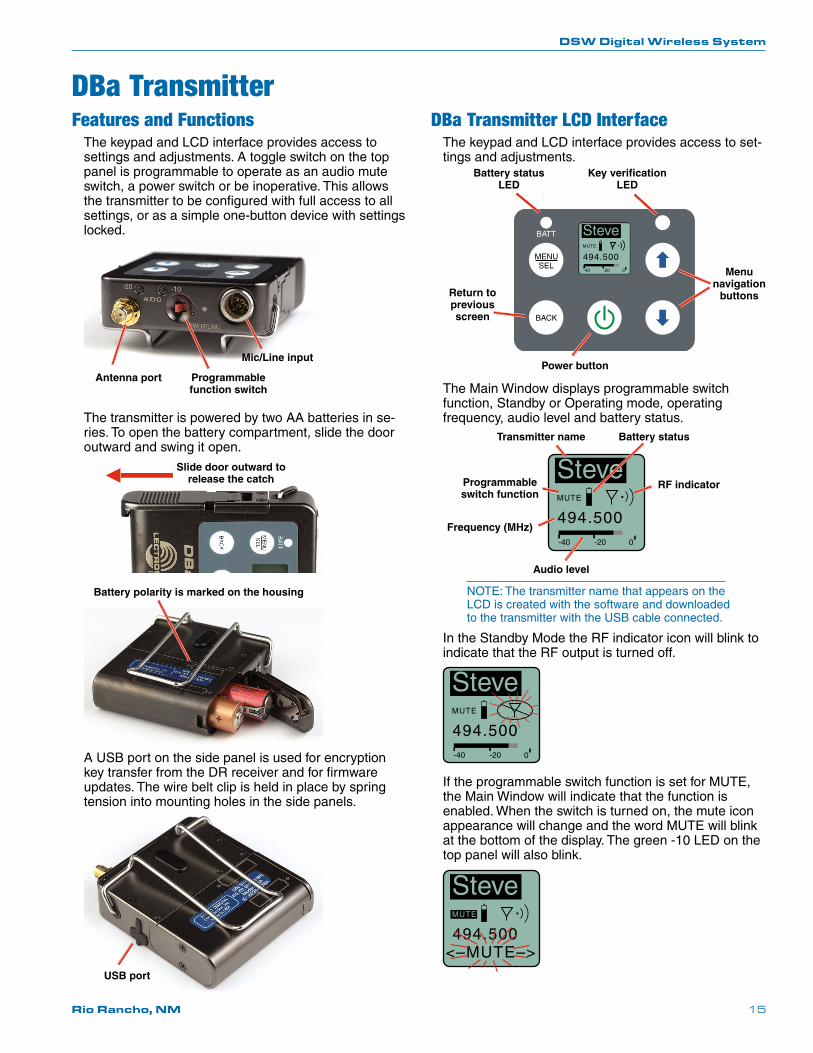
Features and FunctionsThe keypad and LCD interface provides access to settings and adjustments. A toggle switch on the top panel is programmable to operate as an audio mute switch, a power switch or be inoperative. This allows the transmitter to be configured with full access to all settings, or as a simple one-button device with settings locked.
Antenna port Programmable function switch
Mic/Line input
The transmitter is powered by two AA batteries in se-ries. To open the battery compartment, slide the door outward and swing it open.
Slide door outward to release the catch
Battery polarity is marked on the housing
A USB port on the side panel is used for encryption key transfer from the DR receiver and for firmware updates. The wire belt clip is held in place by spring tension into mounting holes in the side panels.
USB port
DSW Digital Wireless System
LECTROSONICS, INC.16
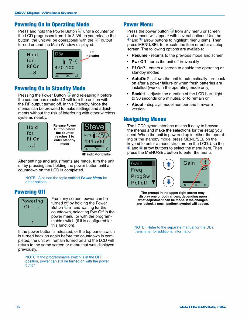
Powering On in Operating ModePress and hold the Power Button until a counter on the LCD progresses from 1 to 3. When you release the button, the unit will be operational with the RF output turned on and the Main Window displayed.
HoldforRf On...3
470.100
-40 -20 +0
DBa RF indicator
Powering On in Standby ModePressing the Power Button and releasing it before the counter has reached 3 will turn the unit on with the RF output turned off. In this Standby Mode the menus can be browsed to make settings and adjust-ments without the risk of interfering with other wireless systems nearby.
Steve
494.500-40 -20 0
MUTE
HoldforRf On...1
Release Power Button before the counter reaches 3 to
enter standby mode
RF indicator blinks
After settings and adjustments are made, turn the unit off by pressing and holding the power button until a countdown on the LCD is completed.
NOTE: Also see the topic entitled Power Menu for other options.
Powering OffPowering O� . . .
1
From any screen, power can be turned off by holding the Power Button in and waiting for the countdown, selecting Pwr Off in the power menu, or with the program-mable switch (if it is configured for this function).
If the power button is released, or the top panel switch is turned back on again before the countdown is com-pleted, the unit will remain turned on and the LCD will return to the same screen or menu that was displayed previously.
NOTE: If the programmable switch is in the OFF position, power can still be turned on with the power button.
Power MenuPress the power button from any menu or screen and a menu will appear with several options. Use the
and arrow buttons to highlight menu items. Then press MENU/SEL to execute the item or enter a setup screen. The following options are available:
• Resume - returns to the previous mode and screen
• Pwr Off - turns the unit off irrevocably
• Rf On? - enters a screen to enable the operating or standby modes
• AutoOn? - allows the unit to automatically turn back on after a power failure or when fresh batteries are installed (works in the operating mode only)
• Backlit - adjusts the duration of the LCD back light to 30 seconds or 5 minutes, or to remain on
• About - displays model number and firmware version
Navigating MenusThe LCD/keypad interface makes it easy to browse the menus and make the selections for the setup you need. When the unit is powered up in either the operat-ing or the standby mode, press MENU/SEL on the keypad to enter a menu structure on the LCD. Use the
and arrow buttons to select the menu item. Then press the MENU/SEL button to enter the menu.
-40 -20 0
Gain25
The prompt in the upper right corner may display one or both arrows, depending upon what adjustment can be made. If the changes
are locked, a small padlock symbol will appear.
GainFreq.ProgSwRolloff
NOTE: Refer to the separate manual for the DBa transmitter for additional information
DSW Digital Wireless System
Rio Rancho, NM 17
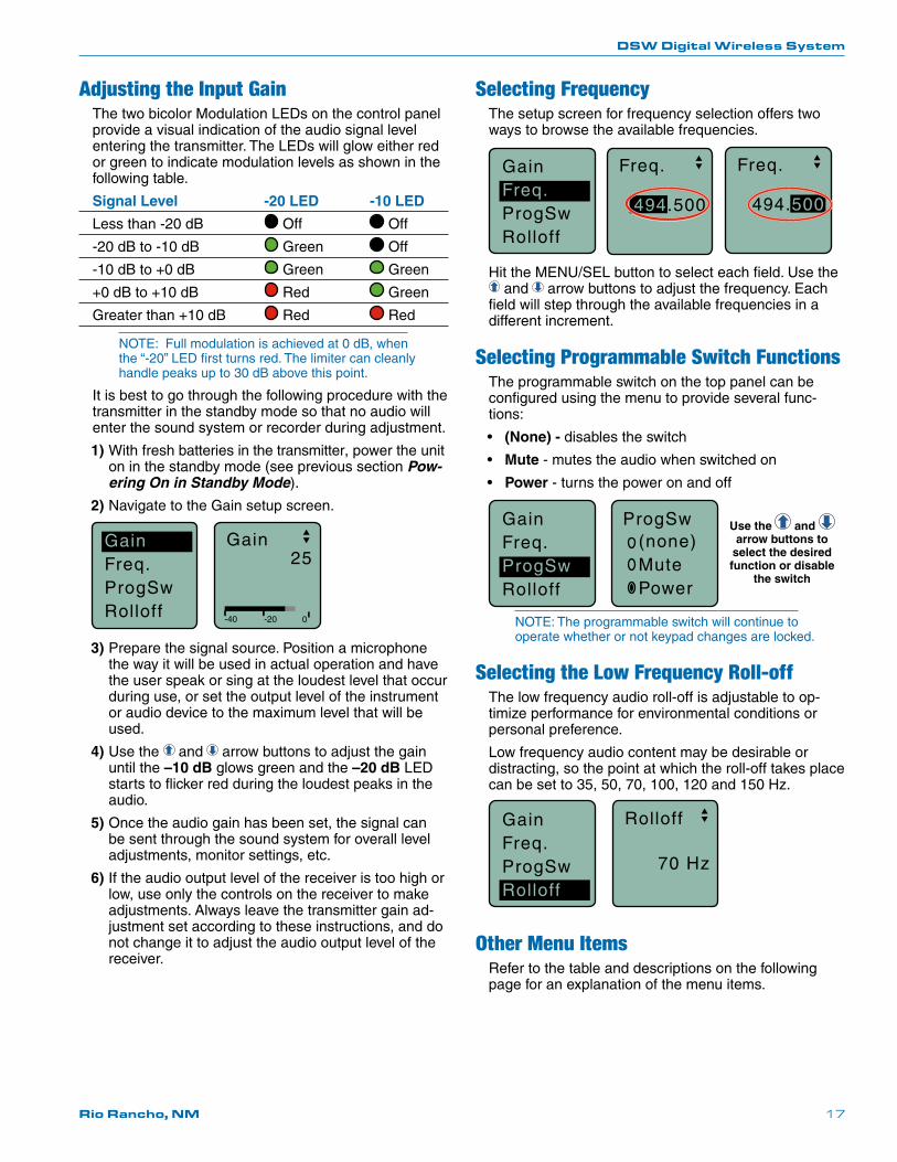
Adjusting the Input GainThe two bicolor Modulation LEDs on the control panel provide a visual indication of the audio signal level entering the transmitter. The LEDs will glow either red or green to indicate modulation levels as shown in the following table.
Signal Level -20 LED -10 LED
Less than -20 dB Off Off
-20 dB to -10 dB Green Off
-10 dB to +0 dB Green Green
+0 dB to +10 dB Red Green
Greater than +10 dB Red Red
NOTE: Full modulation is achieved at 0 dB, when the “-20” LED first turns red. The limiter can cleanly handle peaks up to 30 dB above this point.
It is best to go through the following procedure with the transmitter in the standby mode so that no audio will enter the sound system or recorder during adjustment.
1) With fresh batteries in the transmitter, power the unit on in the standby mode (see previous section Pow-ering On in Standby Mode).
2) Navigate to the Gain setup screen.
GainFreq.ProgSwRolloff -40 -20 0
Gain25
3) Prepare the signal source. Position a microphone the way it will be used in actual operation and have the user speak or sing at the loudest level that occur during use, or set the output level of the instrument or audio device to the maximum level that will be used.
4) Use the and arrow buttons to adjust the gain until the –10 dB glows green and the –20 dB LED starts to flicker red during the loudest peaks in the audio.
5) Once the audio gain has been set, the signal can be sent through the sound system for overall level adjustments, monitor settings, etc.
6) If the audio output level of the receiver is too high or low, use only the controls on the receiver to make adjustments. Always leave the transmitter gain ad-justment set according to these instructions, and do not change it to adjust the audio output level of the receiver.
Selecting FrequencyThe setup screen for frequency selection offers two ways to browse the available frequencies.
GainFreq.ProgSwRolloff
Freq.
494.500
Freq.
494.500
Hit the MENU/SEL button to select each field. Use the and arrow buttons to adjust the frequency. Each
field will step through the available frequencies in a different increment.
Selecting Programmable Switch FunctionsThe programmable switch on the top panel can be configured using the menu to provide several func-tions:
• (None) - disables the switch
• Mute - mutes the audio when switched on
• Power - turns the power on and off
ProgSw(none)MutePower
Use the and arrow buttons to
select the desired function or disable
the switch
GainFreq.ProgSwRolloff
NOTE: The programmable switch will continue to operate whether or not keypad changes are locked.
Selecting the Low Frequency Roll-offThe low frequency audio roll-off is adjustable to op-timize performance for environmental conditions or personal preference.
Low frequency audio content may be desirable or distracting, so the point at which the roll-off takes place can be set to 35, 50, 70, 100, 120 and 150 Hz.
Rolloff
70 Hz
GainFreq.ProgSwRolloff
Other Menu ItemsRefer to the table and descriptions on the following page for an explanation of the menu items.
DSW Digital Wireless System
LECTROSONICS, INC.18
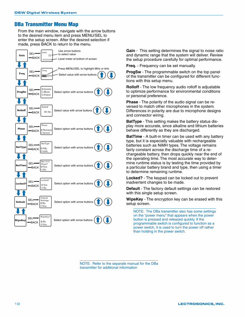
DBa Transmitter Menu MapFrom the main window, navigate with the arrow buttons to the desired menu item and press MENU/SEL to enter the setup screen. After the desired selection if made, press BACK to return to the menu.
SEL
BACK
Freq.
Select option with arrow buttons
Use arrow buttons to select value 22Gain SEL
BACK
Gain
Level meter at bottom of screen
Freq.470.675
Press MENU/SEL to highlight MHz or kHz
SEL
BACKProgSw
(none)MutePower
SEL
BACKRolloff
Rolloff
50 Hz Select value with arrow buttons
SEL
BACKPhase Normal
Invert
Phase
SEL
BACKBatType Alk.
Lith.
BatType
SEL
BACKBatTime
SEL
BACKLocked? Yes
No
Locked?
Bat 5:41Reset?
YesNo
Select value with arrow buttons
Select option with arrow buttons
Select option with arrow buttons
Select option with arrow buttons
Select option with arrow buttons
SEL
BACKDefault
DefaultSettings
NoYes
Select option with arrow buttons
SEL
BACKWipeKey No
Yes
WipeKey?
Select option with arrow buttons
Gain - This setting determines the signal to noise ratio and dynamic range that the system will deliver. Review the setup procedure carefully for optimal performance.
Freq. - Frequency can be set manually.
ProgSw - The programmable switch on the top panel of the transmitter can be configured for different func-tions with this setup menu.
Rolloff - The low frequency audio rolloff is adjustable to optimize performance for environmental conditions or personal preference.
Phase - The polarity of the audio signal can be re-versed to match other microphones in the system. Differences in polarity are due to microphone designs and connector wiring.
BatType - This setting makes the battery status dis-play more accurate, since alkaline and lithium batteries behave differently as they are discharged.
BatTime - A built-in timer can be used with any battery type, but it is especially valuable with rechargeable batteries such as NiMH types. The voltage remains fairly constant across the discharge time of a re-chargeable battery, then drops quickly near the end of the operating time. The most accurate way to deter-mine runtime status is by testing the time provided by a particular battery brand and type, then using a timer to determine remaining runtime.
Locked? - The keypad can be locked out to prevent inadvertent changes to be made.
Default - The factory default settings can be restored with this single setup screen.
WipeKey - The encryption key can be erased with this setup screen.
NOTE: The DBa transmitter also has some settings on the “power menu” that appears when the power button is pressed and released quickly. If the programmable switch is configured to function as a power switch, it is used to turn the power off rather than holding in the power switch.
NOTE: Refer to the separate manual for the DBa transmitter for additional information
DSW Digital Wireless System
Rio Rancho, NM 19
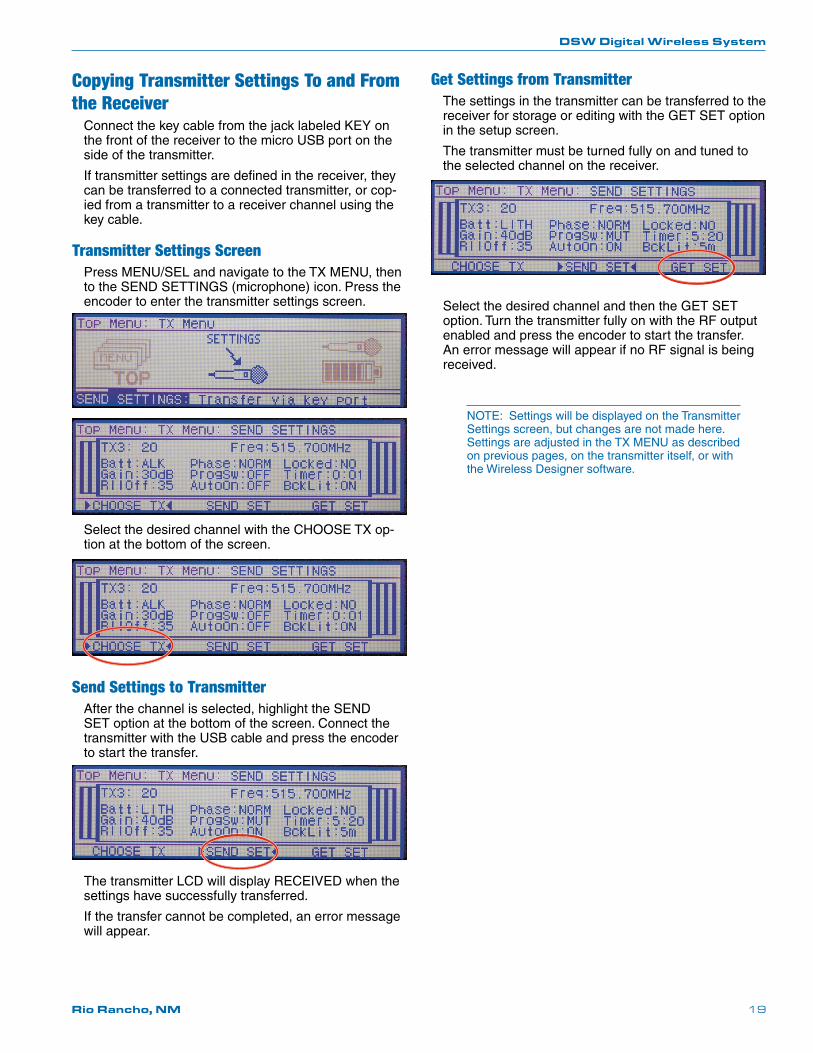
Copying Transmitter Settings To and From the Receiver
Connect the key cable from the jack labeled KEY on the front of the receiver to the micro USB port on the side of the transmitter.
If transmitter settings are defined in the receiver, they can be transferred to a connected transmitter, or cop-ied from a transmitter to a receiver channel using the key cable.
Transmitter Settings ScreenPress MENU/SEL and navigate to the TX MENU, then to the SEND SETTINGS (microphone) icon. Press the encoder to enter the transmitter settings screen.
Select the desired channel with the CHOOSE TX op-tion at the bottom of the screen.
Send Settings to TransmitterAfter the channel is selected, highlight the SEND SET option at the bottom of the screen. Connect the transmitter with the USB cable and press the encoder to start the transfer.
The transmitter LCD will display RECEIVED when the settings have successfully transferred.
If the transfer cannot be completed, an error message will appear.
Get Settings from TransmitterThe settings in the transmitter can be transferred to the receiver for storage or editing with the GET SET option in the setup screen.
The transmitter must be turned fully on and tuned to the selected channel on the receiver.
Select the desired channel and then the GET SET option. Turn the transmitter fully on with the RF output enabled and press the encoder to start the transfer. An error message will appear if no RF signal is being received.
NOTE: Settings will be displayed on the Transmitter Settings screen, but changes are not made here. Settings are adjusted in the TX MENU as described on previous pages, on the transmitter itself, or with the Wireless Designer software.
DSW Digital Wireless System
LECTROSONICS, INC.20
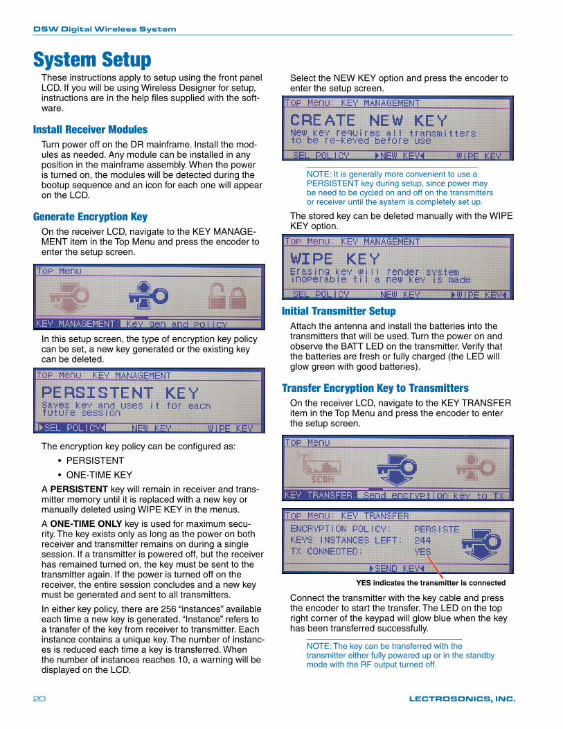
System SetupThese instructions apply to setup using the front panel LCD. If you will be using Wireless Designer for setup, instructions are in the help files supplied with the soft-ware.
Install Receiver ModulesTurn power off on the DR mainframe. Install the mod-ules as needed. Any module can be installed in any position in the mainframe assembly. When the power is turned on, the modules will be detected during the bootup sequence and an icon for each one will appear on the LCD.
Generate Encryption KeyOn the receiver LCD, navigate to the KEY MANAGE-MENT item in the Top Menu and press the encoder to enter the setup screen.
In this setup screen, the type of encryption key policy can be set, a new key generated or the existing key can be deleted.
The encryption key policy can be configured as:
• PERSISTENT
• ONE-TIME KEY
A PERSISTENT key will remain in receiver and trans-mitter memory until it is replaced with a new key or manually deleted using WIPE KEY in the menus.
A ONE-TIME ONLY key is used for maximum secu-rity. The key exists only as long as the power on both receiver and transmitter remains on during a single session. If a transmitter is powered off, but the receiver has remained turned on, the key must be sent to the transmitter again. If the power is turned off on the receiver, the entire session concludes and a new key must be generated and sent to all transmitters.
In either key policy, there are 256 “instances” available each time a new key is generated. “Instance” refers to a transfer of the key from receiver to transmitter. Each instance contains a unique key. The number of instanc-es is reduced each time a key is transferred. When the number of instances reaches 10, a warning will be displayed on the LCD.
Select the NEW KEY option and press the encoder to enter the setup screen.
NOTE: It is generally more convenient to use a PERSISTENT key during setup, since power may be need to be cycled on and off on the transmitters or receiver until the system is completely set up.
The stored key can be deleted manually with the WIPE KEY option.
Initial Transmitter SetupAttach the antenna and install the batteries into the transmitters that will be used. Turn the power on and observe the BATT LED on the transmitter. Verify that the batteries are fresh or fully charged (the LED will glow green with good batteries).
Transfer Encryption Key to TransmittersOn the receiver LCD, navigate to the KEY TRANSFER item in the Top Menu and press the encoder to enter the setup screen.
YES indicates the transmitter is connected
Connect the transmitter with the key cable and press the encoder to start the transfer. The LED on the top right corner of the keypad will glow blue when the key has been transferred successfully.
NOTE: The key can be transferred with the transmitter either fully powered up or in the standby mode with the RF output turned off.
DSW Digital Wireless System
Rio Rancho, NM 21
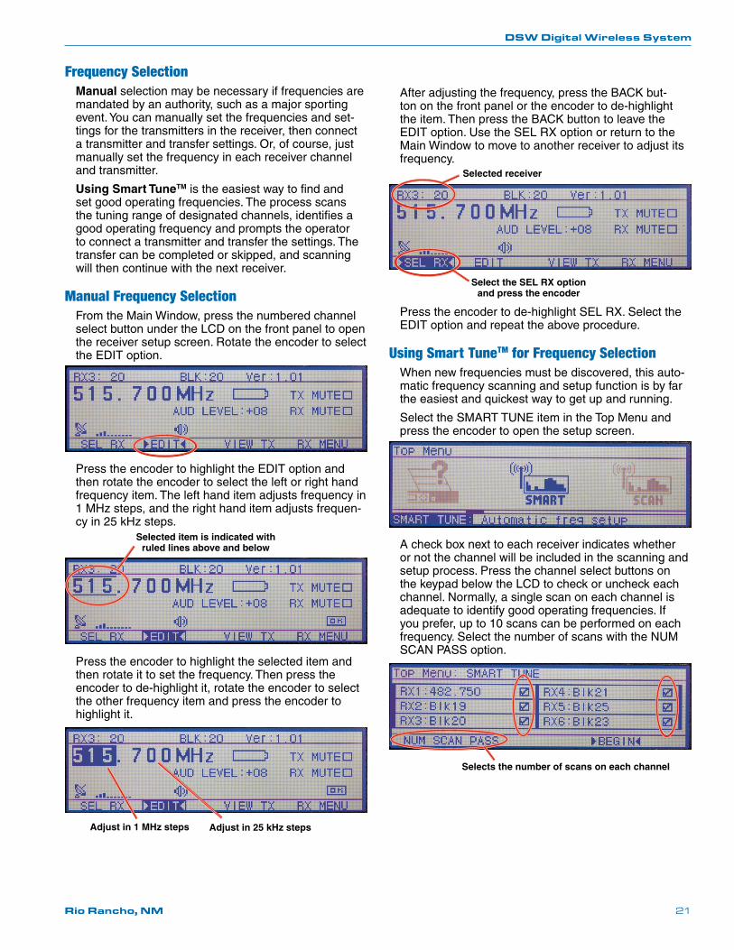
Frequency SelectionManual selection may be necessary if frequencies are mandated by an authority, such as a major sporting event. You can manually set the frequencies and set-tings for the transmitters in the receiver, then connect a transmitter and transfer settings. Or, of course, just manually set the frequency in each receiver channel and transmitter.
Using Smart TuneTM is the easiest way to find and set good operating frequencies. The process scans the tuning range of designated channels, identifies a good operating frequency and prompts the operator to connect a transmitter and transfer the settings. The transfer can be completed or skipped, and scanning will then continue with the next receiver.
Manual Frequency SelectionFrom the Main Window, press the numbered channel select button under the LCD on the front panel to open the receiver setup screen. Rotate the encoder to select the EDIT option.
Press the encoder to highlight the EDIT option and then rotate the encoder to select the left or right hand frequency item. The left hand item adjusts frequency in 1 MHz steps, and the right hand item adjusts frequen-cy in 25 kHz steps.
Selected item is indicated with ruled lines above and below
Press the encoder to highlight the selected item and then rotate it to set the frequency. Then press the encoder to de-highlight it, rotate the encoder to select the other frequency item and press the encoder to highlight it.
Adjust in 1 MHz steps Adjust in 25 kHz steps
After adjusting the frequency, press the BACK but-ton on the front panel or the encoder to de-highlight the item. Then press the BACK button to leave the EDIT option. Use the SEL RX option or return to the Main Window to move to another receiver to adjust its frequency.
Selected receiver
Select the SEL RX option and press the encoder
Press the encoder to de-highlight SEL RX. Select the EDIT option and repeat the above procedure.
Using Smart TuneTM for Frequency SelectionWhen new frequencies must be discovered, this auto-matic frequency scanning and setup function is by far the easiest and quickest way to get up and running.
Select the SMART TUNE item in the Top Menu and press the encoder to open the setup screen.
A check box next to each receiver indicates whether or not the channel will be included in the scanning and setup process. Press the channel select buttons on the keypad below the LCD to check or uncheck each channel. Normally, a single scan on each channel is adequate to identify good operating frequencies. If you prefer, up to 10 scans can be performed on each frequency. Select the number of scans with the NUM SCAN PASS option.
Selects the number of scans on each channel
DSW Digital Wireless System
LECTROSONICS, INC.22
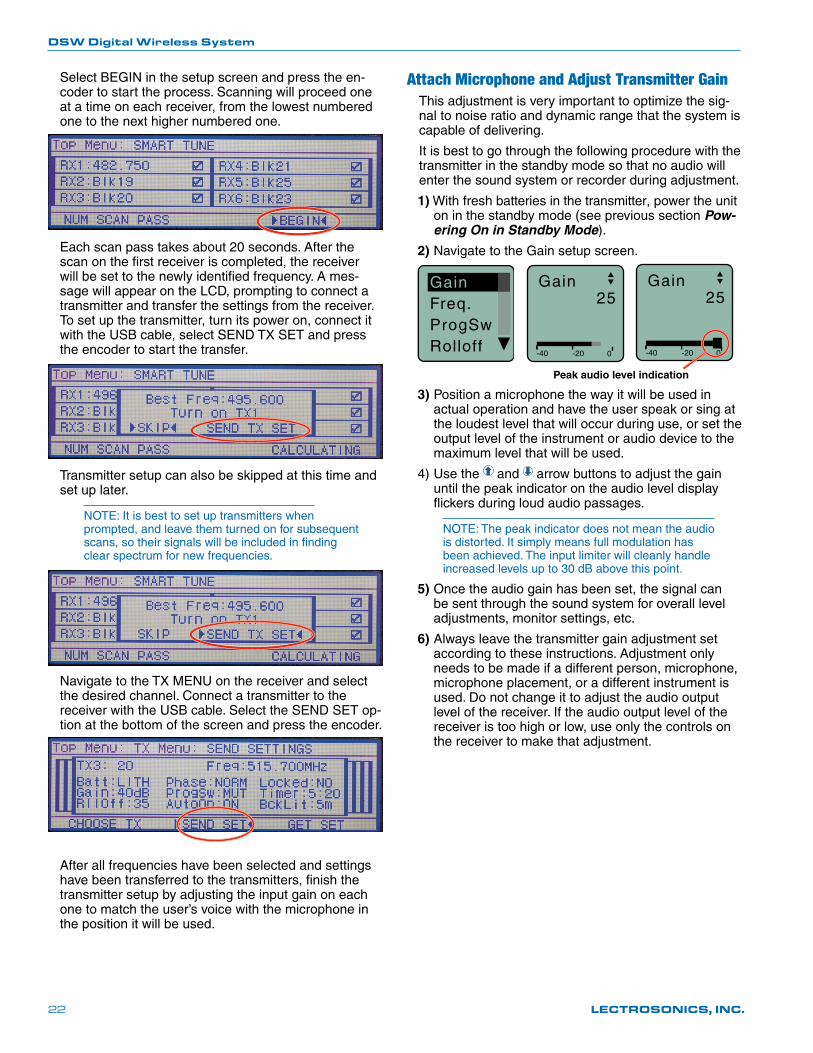
Select BEGIN in the setup screen and press the en-coder to start the process. Scanning will proceed one at a time on each receiver, from the lowest numbered one to the next higher numbered one.
Each scan pass takes about 20 seconds. After the scan on the first receiver is completed, the receiver will be set to the newly identified frequency. A mes-sage will appear on the LCD, prompting to connect a transmitter and transfer the settings from the receiver. To set up the transmitter, turn its power on, connect it with the USB cable, select SEND TX SET and press the encoder to start the transfer.
Transmitter setup can also be skipped at this time and set up later.
NOTE: It is best to set up transmitters when prompted, and leave them turned on for subsequent scans, so their signals will be included in finding clear spectrum for new frequencies.
Navigate to the TX MENU on the receiver and select the desired channel. Connect a transmitter to the receiver with the USB cable. Select the SEND SET op-tion at the bottom of the screen and press the encoder.
After all frequencies have been selected and settings have been transferred to the transmitters, finish the transmitter setup by adjusting the input gain on each one to match the user’s voice with the microphone in the position it will be used.
Attach Microphone and Adjust Transmitter GainThis adjustment is very important to optimize the sig-nal to noise ratio and dynamic range that the system is capable of delivering.
It is best to go through the following procedure with the transmitter in the standby mode so that no audio will enter the sound system or recorder during adjustment.
1) With fresh batteries in the transmitter, power the unit on in the standby mode (see previous section Pow-ering On in Standby Mode).
2) Navigate to the Gain setup screen.
GainFreq.ProgSwRolloff -40 -20 0
Gain25
-40 -20 0
Gain25
Peak audio level indication
3) Position a microphone the way it will be used in actual operation and have the user speak or sing at the loudest level that will occur during use, or set the output level of the instrument or audio device to the maximum level that will be used.
4) Use the and arrow buttons to adjust the gain until the peak indicator on the audio level display flickers during loud audio passages.
NOTE: The peak indicator does not mean the audio is distorted. It simply means full modulation has been achieved. The input limiter will cleanly handle increased levels up to 30 dB above this point.
5) Once the audio gain has been set, the signal can be sent through the sound system for overall level adjustments, monitor settings, etc.
6) Always leave the transmitter gain adjustment set according to these instructions. Adjustment only needs to be made if a different person, microphone, microphone placement, or a different instrument is used. Do not change it to adjust the audio output level of the receiver. If the audio output level of the receiver is too high or low, use only the controls on the receiver to make that adjustment.
DSW Digital Wireless System
Rio Rancho, NM 23
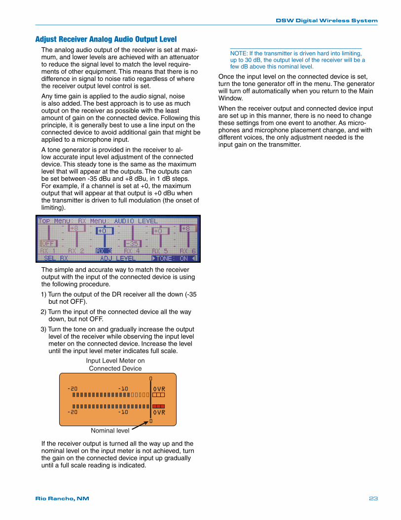
Adjust Receiver Analog Audio Output LevelThe analog audio output of the receiver is set at maxi-mum, and lower levels are achieved with an attenuator to reduce the signal level to match the level require-ments of other equipment. This means that there is no difference in signal to noise ratio regardless of where the receiver output level control is set.
Any time gain is applied to the audio signal, noise is also added. The best approach is to use as much output on the receiver as possible with the least amount of gain on the connected device. Following this principle, it is generally best to use a line input on the connected device to avoid additional gain that might be applied to a microphone input.
A tone generator is provided in the receiver to al-low accurate input level adjustment of the connected device. This steady tone is the same as the maximum level that will appear at the outputs. The outputs can be set between -35 dBu and +8 dBu, in 1 dB steps. For example, if a channel is set at +0, the maximum output that will appear at that output is +0 dBu when the transmitter is driven to full modulation (the onset of limiting).
The simple and accurate way to match the receiver output with the input of the connected device is using the following procedure.
1) Turn the output of the DR receiver all the down (-35 but not OFF).
2) Turn the input of the connected device all the way down, but not OFF.
3) Turn the tone on and gradually increase the output level of the receiver while observing the input level meter on the connected device. Increase the level until the input level meter indicates full scale.
OVR
OVR
-20
0
-10
-20
0
-10
Input Level Meter on Connected Device
Nominal level
If the receiver output is turned all the way up and the nominal level on the input meter is not achieved, turn the gain on the connected device input up gradually until a full scale reading is indicated.
NOTE: If the transmitter is driven hard into limiting, up to 30 dB, the output level of the receiver will be a few dB above this nominal level.
Once the input level on the connected device is set, turn the tone generator off in the menu. The generator will turn off automatically when you return to the Main Window.
When the receiver output and connected device input are set up in this manner, there is no need to change these settings from one event to another. As micro-phones and microphone placement change, and with different voices, the only adjustment needed is the input gain on the transmitter.
DSW Digital Wireless System
LECTROSONICS, INC.24
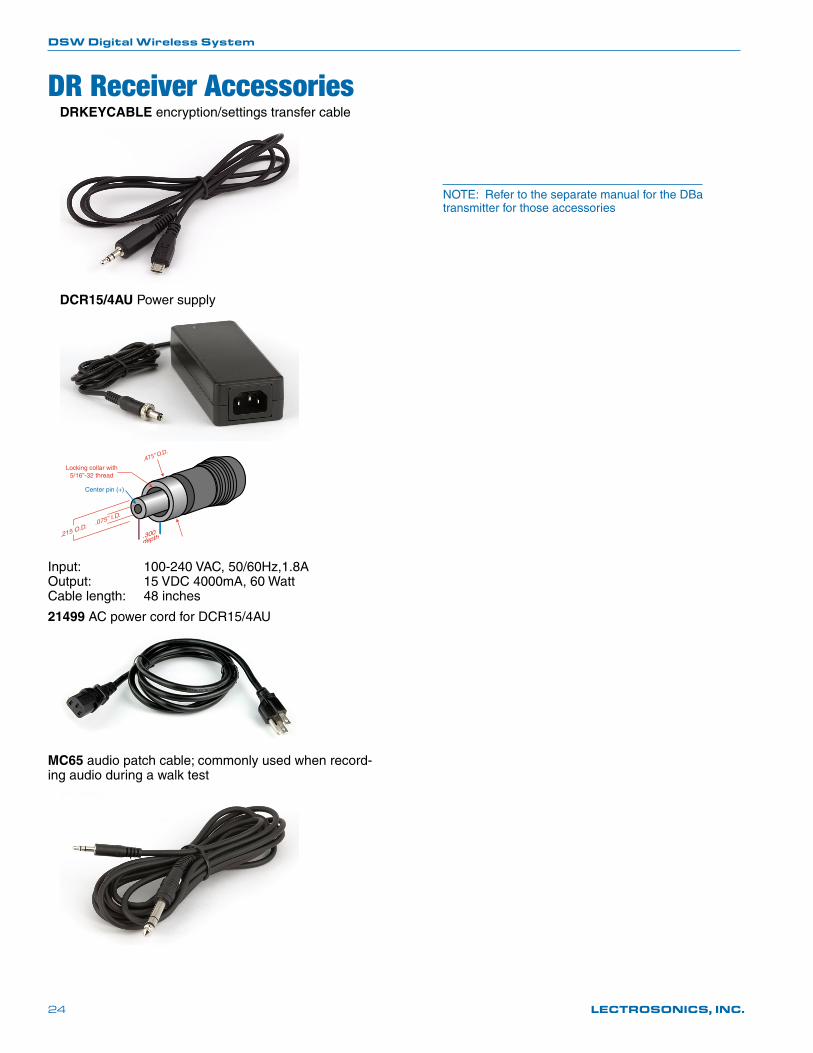
DR Receiver AccessoriesDRKEYCABLE encryption/settings transfer cable
DCR15/4AU Power supply
.475” O.D.
Locking collar with5/16”-32 thread
Input: 100-240 VAC, 50/60Hz,1.8A Output: 15 VDC 4000mA, 60 Watt Cable length: 48 inches
21499 AC power cord for DCR15/4AU
MC65 audio patch cable; commonly used when record-ing audio during a walk test
NOTE: Refer to the separate manual for the DBa transmitter for those accessories
DSW Digital Wireless System
Rio Rancho, NM 25
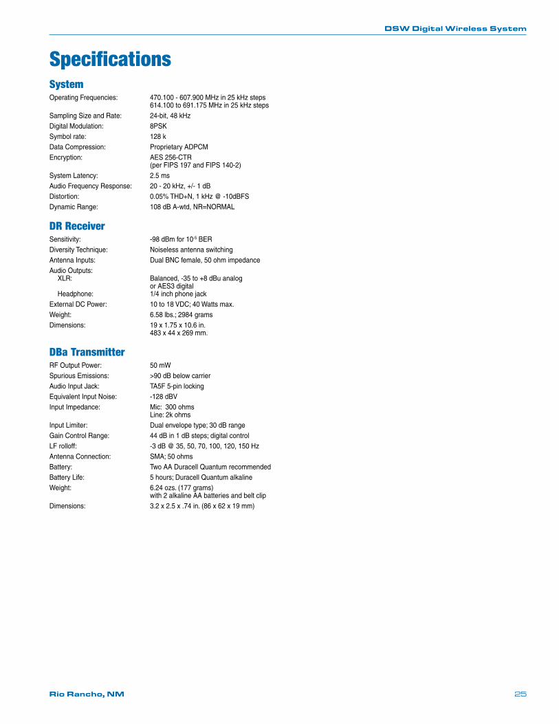
SpecificationsSystemOperating Frequencies: 470.100 - 607.900 MHz in 25 kHz steps 614.100 to 691.175 MHz in 25 kHz stepsSampling Size and Rate: 24-bit, 48 kHzDigital Modulation: 8PSKSymbol rate: 128 kData Compression: Proprietary ADPCMEncryption: AES 256-CTR (per FIPS 197 and FIPS 140-2)System Latency: 2.5 msAudio Frequency Response: 20 - 20 kHz, +/- 1 dBDistortion: 0.05% THD+N, 1 kHz @ -10dBFSDynamic Range: 108 dB A-wtd, NR=NORMAL
DR ReceiverSensitivity: -98 dBm for 10-5 BERDiversity Technique: Noiseless antenna switchingAntenna Inputs: Dual BNC female, 50 ohm impedanceAudio Outputs: XLR: Balanced, -35 to +8 dBu analog or AES3 digital Headphone: 1/4 inch phone jackExternal DC Power: 10 to 18 VDC; 40 Watts max.Weight: 6.58 lbs.; 2984 gramsDimensions: 19 x 1.75 x 10.6 in. 483 x 44 x 269 mm.
DBa TransmitterRF Output Power: 50 mWSpurious Emissions: >90 dB below carrierAudio Input Jack: TA5F 5-pin lockingEquivalent Input Noise: -128 dBVInput Impedance: Mic: 300 ohms Line: 2k ohmsInput Limiter: Dual envelope type; 30 dB rangeGain Control Range: 44 dB in 1 dB steps; digital controlLF rolloff: -3 dB @ 35, 50, 70, 100, 120, 150 HzAntenna Connection: SMA; 50 ohmsBattery: Two AA Duracell Quantum recommendedBattery Life: 5 hours; Duracell Quantum alkalineWeight: 6.24 ozs. (177 grams) with 2 alkaline AA batteries and belt clipDimensions: 3.2 x 2.5 x .74 in. (86 x 62 x 19 mm)
DSW Digital Wireless System
LECTROSONICS, INC.26
Service and RepairIf your system malfunctions, you should attempt to correct or isolate the trouble before concluding that the equip-ment needs repair. Make sure you have followed the setup procedure and operating instructions. Check the inter-connecting cables and then go through the Troubleshooting section in this manual.
We strongly recommend that you do not try to repair the equipment yourself and do not have the local repair shop attempt anything other than the simplest repair. If the repair is more complicated than a broken wire or loose con-nection, send the unit to the factory for repair and service. Don’t attempt to adjust any controls inside the units. Once set at the factory, the various controls and trimmers do not drift with age or vibration and never require readjustment. There are no adjustments inside that will make a malfunctioning unit start working.
LECTROSONICS’ Service Department is equipped and staffed to quickly repair your equipment. In warranty repairs are made at no charge in accordance with the terms of the warranty. Out-of-warranty repairs are charged at a mod-est flat rate plus parts and shipping. Since it takes almost as much time and effort to determine what is wrong as it does to make the repair, there is a charge for an exact quotation. We will be happy to quote approximate charges by phone for out-of-warranty repairs.
Returning Units for RepairFor timely service, please follow the steps below:
A. DO NOT return equipment to the factory for repair without first contacting us by email or by phone. We need to know the nature of the problem, the model number and the serial number of the equipment. We also need a phone number where you can be reached 8 A.M. to 4 P.M. (U.S. Mountain Standard Time).
B. After receiving your request, we will issue you a return authorization number (R.A.). This number will help speed your repair through our receiving and repair departments. The return authorization number must be clearly shown on the outside of the shipping container.
C. Pack the equipment carefully and ship to us, shipping costs prepaid. If necessary, we can provide you with the proper packing materials. UPS is usually the best way to ship the units. Heavy units should be “double-boxed” for safe transport.
D. We also strongly recommend that you insure the equipment, since we cannot be responsible for loss of or dam-age to equipment that you ship. Of course, we insure the equipment when we ship it back to you.
Lectrosonics USA:
Mailing address: Shipping address: Telephone: Lectrosonics, Inc. Lectrosonics, Inc. (505) 892-4501 PO Box 15900 561 Laser Rd. Ste. 102 (800) 821-1121 Toll-free Rio Rancho, NM 87174 Rio Rancho, NM 87124 (505) 892-6243 Fax USA USA
Web: E-mail: www.lectrosonics.com [email protected]
Lectrosonics Canada:
Mailing address: Telephone: Lectrosonics Canada (877) 753-2876 Toll-free 720 Spadina Ave, Suite 600 (416) 596-2202 Toll-free Toronto, Ontario M5S 2T9 (416) 596-6648 Fax

DSW Digital Wireless System
Rio Rancho, NM 27
09 February 2017
581 Laser Road NE • Rio Rancho, NM 87124 USA • www.lectrosonics.com(505) 892-4501 • (800) 821-1121 • fax (505) 892-6243 • [email protected]
LIMITED ONE YEAR WARRANTYThe equipment is warranted for one year from date of purchase against defects in materials or workmanship provided it was purchased from an authorized dealer. This warranty does not cover equipment which has been abused or damaged by careless handling or shipping. This warranty does not apply to used or demonstrator equipment.
Should any defect develop, Lectrosonics, Inc. will, at our option, repair or replace any defective parts without charge for either parts or labor. If Lectrosonics, Inc. cannot correct the defect in your equipment, it will be replaced at no charge with a similar new item. Lectrosonics, Inc. will pay for the cost of returning your equipment to you.
This warranty applies only to items returned to Lectrosonics, Inc. or an authorized dealer, shipping costs prepaid, within one year from the date of purchase.
This Limited Warranty is governed by the laws of the State of New Mexico. It states the entire liablility of Lectrosonics Inc. and the entire remedy of the purchaser for any breach of warranty as outlined above. NEITHER LECTROSONICS, INC. NOR ANYONE INVOLVED IN THE PRODUCTION OR DELIVERY OF THE EQUIPMENT SHALL BE LIABLE FOR ANY INDIRECT, SPECIAL, PUNITIVE, CONSEQUENTIAL, OR INCIDENTAL DAMAGES ARISING OUT OF THE USE OR INABILITY TO USE THIS EQUIPMENT EVEN IF LECTROSONICS, INC. HAS BEEN ADVISED OF THE POSSIBILITY OF SUCH DAMAGES. IN NO EVENT SHALL THE LIABILITY OF LECTROSONICS, INC. EXCEED THE PURCHASE PRICE OF ANY DEFECTIVE EQUIPMENT.
This warranty gives you specific legal rights. You may have additional legal rights which vary from state to state.