Instruction manual - Weil-McLain · When applying outdoor reset to a hydronic system, review boiler...
8
Part Number 550-141-860/0107 This manual must only be used by a qualified heating installer/service technician. Failure to comply could result in severe personal injury, death or substantial property damage. Instruction manual
Transcript of Instruction manual - Weil-McLain · When applying outdoor reset to a hydronic system, review boiler...
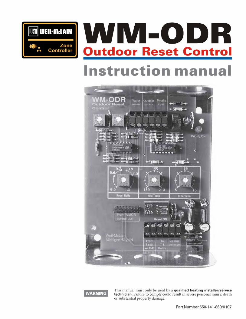
Part Number 550-141-860/0107
This manual must only be used by a qualified heating installer/servicetechnician. Failure to comply could result in severe personal injury, deathor substantial property damage.
Instruction manual
2
WM-WM-WM-WM-WM-ODR Outdoor RODR Outdoor RODR Outdoor RODR Outdoor RODR Outdoor Reset Controleset Controleset Controleset Controleset Control
Part number 550-141-860/0107
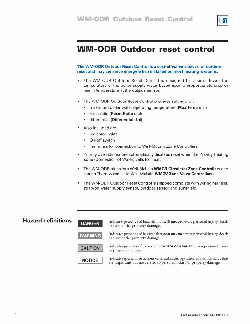
Hazard definitions Indicates presence of hazards that will cause severe personal injury, deathor substantial property damage.
Indicates presence of hazards that can cause severe personal injury, deathor substantial property damage.
Indicates presence of hazards that will or can cause minor personal injuryor property damage.
Indicates special instructions on installation, operation or maintenance thatare important but not related to personal injury or property damage.
The WM-ODR Outdoor Reset Control is a cost-effective answer for outdoorreset and may conserve energy when installed on most heating systems.
• The WM-ODR Outdoor Reset Control is designed to raise or lower thetemperature of the boiler supply water based upon a proportionate drop orrise in temperature at the outside sensor.
• The WM-ODR Outdoor Reset Control provides settings for:
• maximum boiler water operating temperature (Max Temp dial)
• reset ratio (Reset Ratio dial)
• differential (Differential dial).
• Also included are:
• Indicator lights
• On-off switch
• Terminals for connection to Weil-McLain Zone Controllers.
• Priority override feature automatically disables reset when the Priority HeatingZone (Domestic Hot Water) calls for heat.
• The WM-ODR plugs into Weil-McLain WMCR Circulator Zone Controllers andcan be “hard-wired” into Weil-McLain WMZV Zone Valve Controllers.
• The WM-ODR Outdoor Reset Control is shipped complete with wiring harness,strap-on water supply sensor, outdoor sensor and sunshield.
WM-ODR Outdoor reset control
Instruction manual
Part number 550-141-860/0107 3
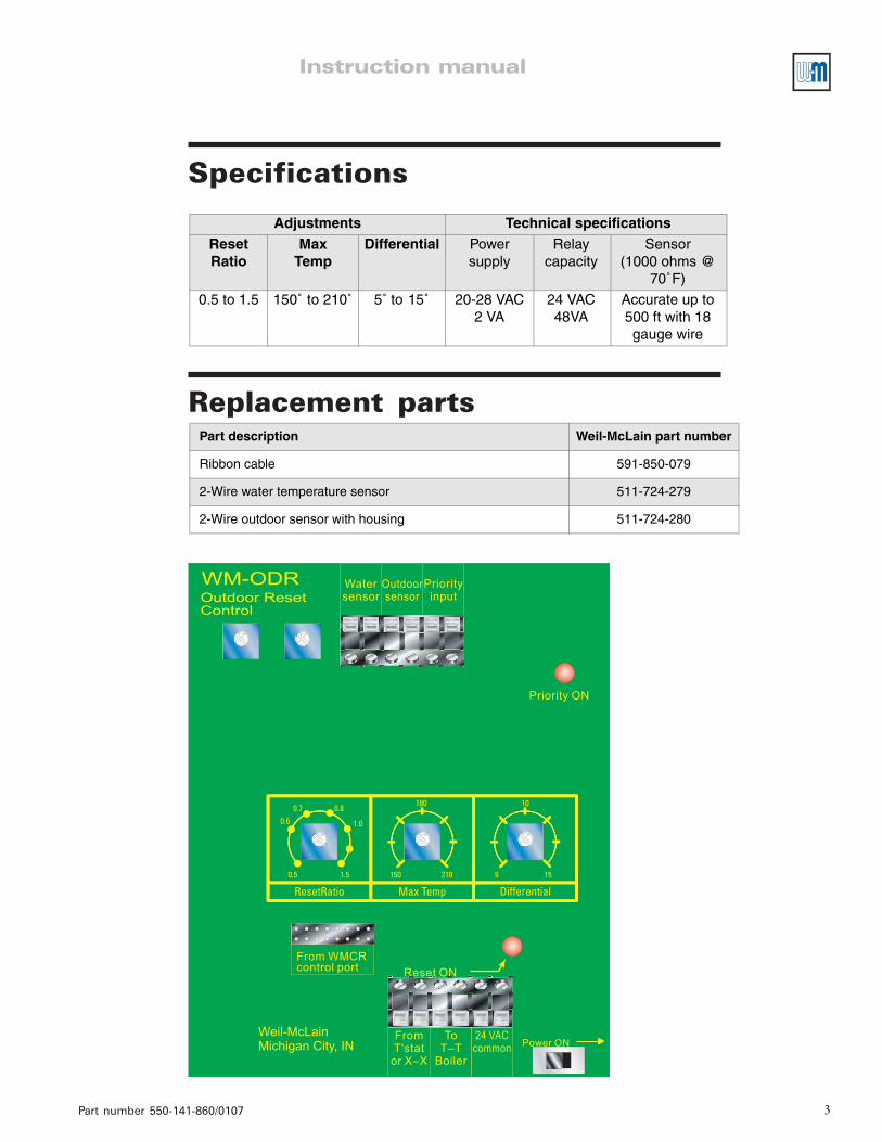
Specifications
Replacement parts
Adjustments Technical specificationsReset Ratio
MaxTemp
Differential Power supply
Relay capacity
Sensor(1000 ohms @
70˚F)
0.5 to 1.5 150˚ to 210˚ 5˚ to 15˚ 20-28 VAC 2 VA
24 VAC48VA
Accurate up to 500 ft with 18 gauge wire
Part description Weil-McLain part number
Ribbon cable 591-850-079
2-Wire water temperature sensor 511-724-279
2-Wire outdoor sensor with housing 511-724-280

4
WM-WM-WM-WM-WM-ODR Outdoor RODR Outdoor RODR Outdoor RODR Outdoor RODR Outdoor Reset Controleset Controleset Controleset Controleset Control
Part number 550-141-860/0107
Installation
Outdoor sensor
Figure 1
Outdoor sensor installation
When applying outdoor reset to a hydronic system, review boiler instructionmanual for any special piping requirements needed for low temperatureoperation. Outdoor reset controls will cause sustained operation below140°F. Failure to pipe boiler in accordance with boiler manufacturer’srecommendations could result in damage to the boiler, causing severepersonal injury, death or substantial property damage.
Install on the North side or a shaded side of the building. Locate a minimum of 10 feet abovegrade or 3 feet above anticipated maximum snow level and not near any place where internalheat could affect the sensor reading, such as windows, doors, exhaust vents or fans.
Figure 2
Water supply sensorinstallation
Water sensor Install the water sensor on the common supply header.
Locate outdoor sensor onNorth wall — no exposureto sunlight
Outdoorsensor
Conduit clamp(by others)
Conduit(by others)
86003
Prevent outdoor sensor from beingcovered by snow. The sensor wouldbe unable to correctly sense outdoortemperature, causing possibleincorrect system water temperatureregulation.
Strap sensor to main supply fromboiler using nylon cable tie.
Wrap sensor and pipe with pipe insulation (by others)to assure sensor will correctly sense water temp.
86004
Instruction manual
Part number 550-141-860/0107 5
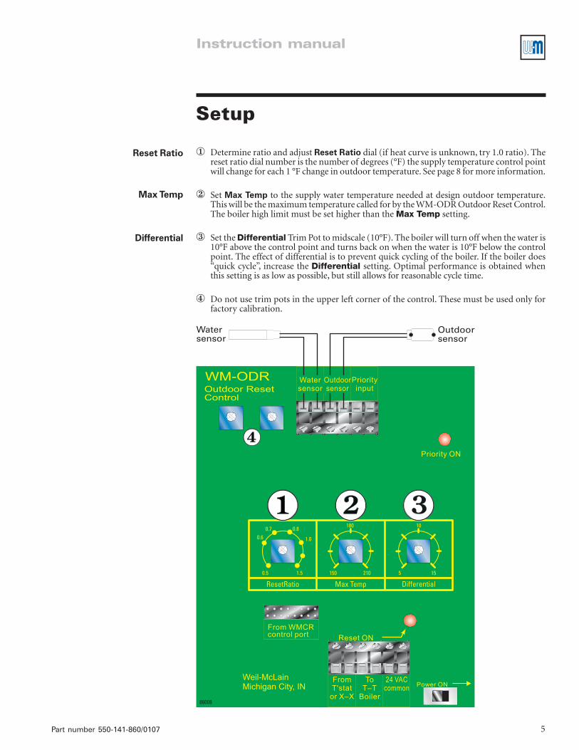
Setup
① Determine ratio and adjust Reset Ratio dial (if heat curve is unknown, try 1.0 ratio). Thereset ratio dial number is the number of degrees (°F) the supply temperature control pointwill change for each 1 °F change in outdoor temperature. See page 8 for more information.
② Set Max Temp to the supply water temperature needed at design outdoor temperature.This will be the maximum temperature called for by the WM-ODR Outdoor Reset Control.The boiler high limit must be set higher than the Max Temp setting.
③ Set the Differential Trim Pot to midscale (10°F). The boiler will turn off when the water is10°F above the control point and turns back on when the water is 10°F below the controlpoint. The effect of differential is to prevent quick cycling of the boiler. If the boiler does“quick cycle”, increase the Differential setting. Optimal performance is obtained whenthis setting is as low as possible, but still allows for reasonable cycle time.
④ Do not use trim pots in the upper left corner of the control. These must be used only forfactory calibration.
Reset Ratio
Max Temp
Differential
6
WM-WM-WM-WM-WM-ODR Outdoor RODR Outdoor RODR Outdoor RODR Outdoor RODR Outdoor Reset Controleset Controleset Controleset Controleset Control
Part number 550-141-860/0107
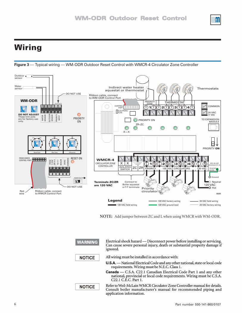
NOTE: Add jumper between ZC and L when using WMCR with WM-ODR.
Wiring
Figure 3 — Typical wiring — WM-ODR Outdoor Reset Control with WMCR-4 Circulator Zone Controller
Electrical shock hazard — Disconnect power before installing or servicing.Can cause severe personal injury, death or substantial property damage ifignored.
All wiring must be installed in accordance with:
U.S.A. — National Electrical Code and any other national, state or local coderequirements. Wiring must be N.E.C. Class 1.
Canada — C.S.A. C22.1 Canadian Electrical Code Part 1 and any othernational, provincial or local code requirements. Wiring must be C.S.A.C22.1 C.E.C. Part 1.
Refer to Weil-McLain WMCR Circulator Zone Controller manual for details.Consult boiler manufacturer’s manual for recommended piping andapplication information.
Instruction manual
Part number 550-141-860/0107 7
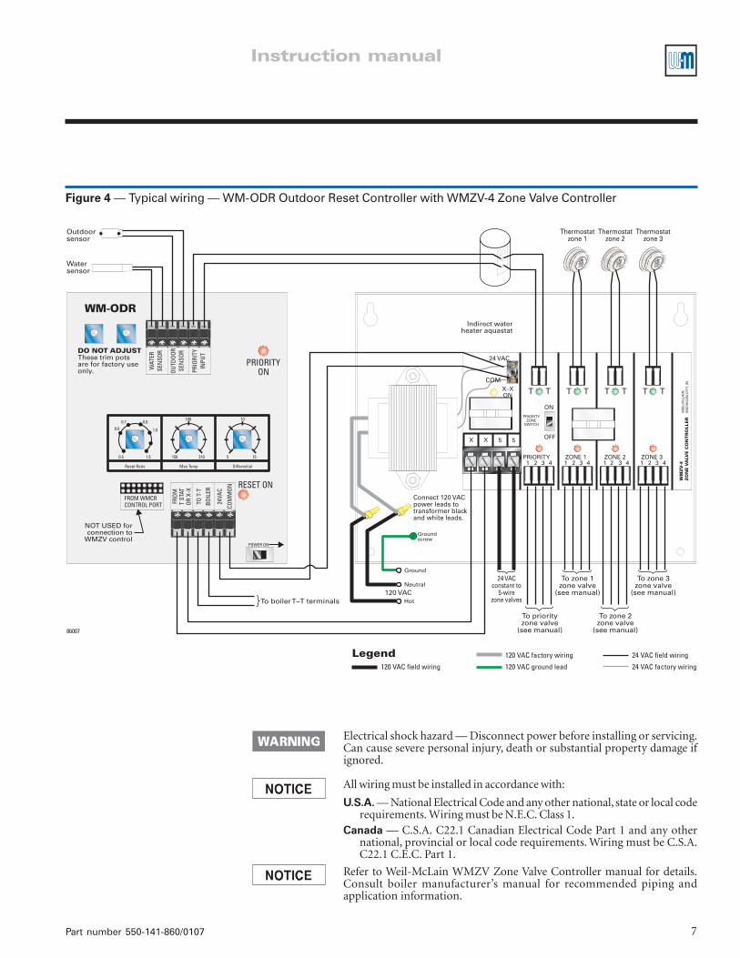
Figure 4 — Typical wiring — WM-ODR Outdoor Reset Controller with WMZV-4 Zone Valve Controller
Electrical shock hazard — Disconnect power before installing or servicing.Can cause severe personal injury, death or substantial property damage ifignored.
All wiring must be installed in accordance with:
U.S.A. — National Electrical Code and any other national, state or local coderequirements. Wiring must be N.E.C. Class 1.
Canada — C.S.A. C22.1 Canadian Electrical Code Part 1 and any othernational, provincial or local code requirements. Wiring must be C.S.A.C22.1 C.E.C. Part 1.
Refer to Weil-McLain WMZV Zone Valve Controller manual for details.Consult boiler manufacturer’s manual for recommended piping andapplication information.

8
WM-WM-WM-WM-WM-ODR Outdoor RODR Outdoor RODR Outdoor RODR Outdoor RODR Outdoor Reset Controleset Controleset Controleset Controleset Control
Part Number 550-141-860/0107
SettingsTo obtain the best operation from a reset control, it is important to monitor the system supply temperature asaccurately as possible. The system pump must be operating to maintain continuous water flow across thesupply temperature sensor.
Heating Curve (Reset Ratio)As outdoor temperature drops, heat loss from a spacebecomes greater, and the heating system supply watertemperature must be increased to maintain a constantroom temperature. The heating curve value (ResetRatio) describes how many degrees the supply watertemperature is raised for a one degree drop in outdoortemperature. The supply temperature starts to increasewhen the outdoor temperature falls below 70 °F.
To calculate the correct setting for the heating curve,use the Reset Ratio formula, below right.
If the actual Design supply water temperaturefor a system is unknown, calculate a trial setting forReset Ratio using these typical supply temperatures:
• Fan coils 180 °F to 210 °F
• Baseboard convectors 160 °F to 190 °F
• Radiant floors, typical 100 °F to 130 °F
• Design outdoor temperature = 5 °F
• Design supply temperature = 160 °F
Reset Ratio =
Example:
Design supply temperature - 70 °F
70 °F - Design outdoor temperature
160 °F - 70 °F
70 °F - 5 °F
90 °F
65 °F1.4==Reset Ratio =