INSTRUCTION MANUAL Washbasin lifts - Barrier … system / Electric circuit diagram.....26 18....
28
4130 4140 4170 Washbasin lifts 4130/4140/4170 Doc. No: M41xx Edition: 1 Date: 2008-05-06 INSTRUCTION MANUAL Washbasin lifts Granberg Interior AB Box 6112 SE-600 06 Norrköping SWEDEN English
Transcript of INSTRUCTION MANUAL Washbasin lifts - Barrier … system / Electric circuit diagram.....26 18....
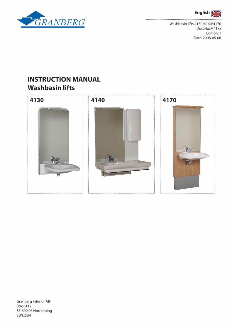
4130 4140 4170
Washbasin lifts 4130/4140/4170 Doc. No: M41xx
Edition: 1Date: 2008-05-06
INSTRUCTION MANUAL Washbasin lifts
Granberg Interior AB Box 6112SE-600 06 NorrköpingSWEDEN
English
More information: www.granberg.se

Section: Headline: Page 1. Introduction..............................................................................................................42. Declaration of Conformity...................................................................................................................53. Intended use - Technical data.........................................................................................................54.1 Preparations - joist heights for model 4130/4140/4170.........................................................64.2 Preparations - installation of sewerage and electric connection 4130/4140/4170.......7 5.1 General information - mounting of lifting mechanism model 4130/4140/4170.............8
Installation instructions Washbasin lift 41306.1 Mechanical construction.....................................................................................................................96.2 Delivery modules..................................................................................................................................96.3 Mounting........................................................................................................................9
Installation instructions Washbasin lift 41407.1 Mechanical construction...................................................................................................................137.2 Delivery modules................................................................................................................................137.3 Mounting........................................................................................................................14
Installation instructions Washbasin lift 41708.1 Mechanical construction...................................................................................................................168.2 Delivery modules................................................................................................................................168.3 Mounting........................................................................................................................17 9. Functional test.......................................................................................................................................20
Operators information10.1 Safe use.....................................................................................................................................................20 10.2 Load distribution and side forces.................................................................................................21 10.3 Actions after use..................................................................................................................................21 10.4 Control device options......................................................................................................................2110.5 Cleaning..........................................................................................................................22 10.6 Maintenance................................................................................................................22 11. Instructions for Recycling.................................................................................................................23 12. Decals.......................................................................................................................23 13. Warranty.....................................................................................................................23 14. Service & maintenance records....................................................................................................24 15. Faultfinding...........................................................................................................2516. Spare parts list.....................................................................................................................................25 17. Electric system / Electric circuit diagram....................................................................................26 18. CE-declaration of Conformity.........................................................................................................27
Content

4
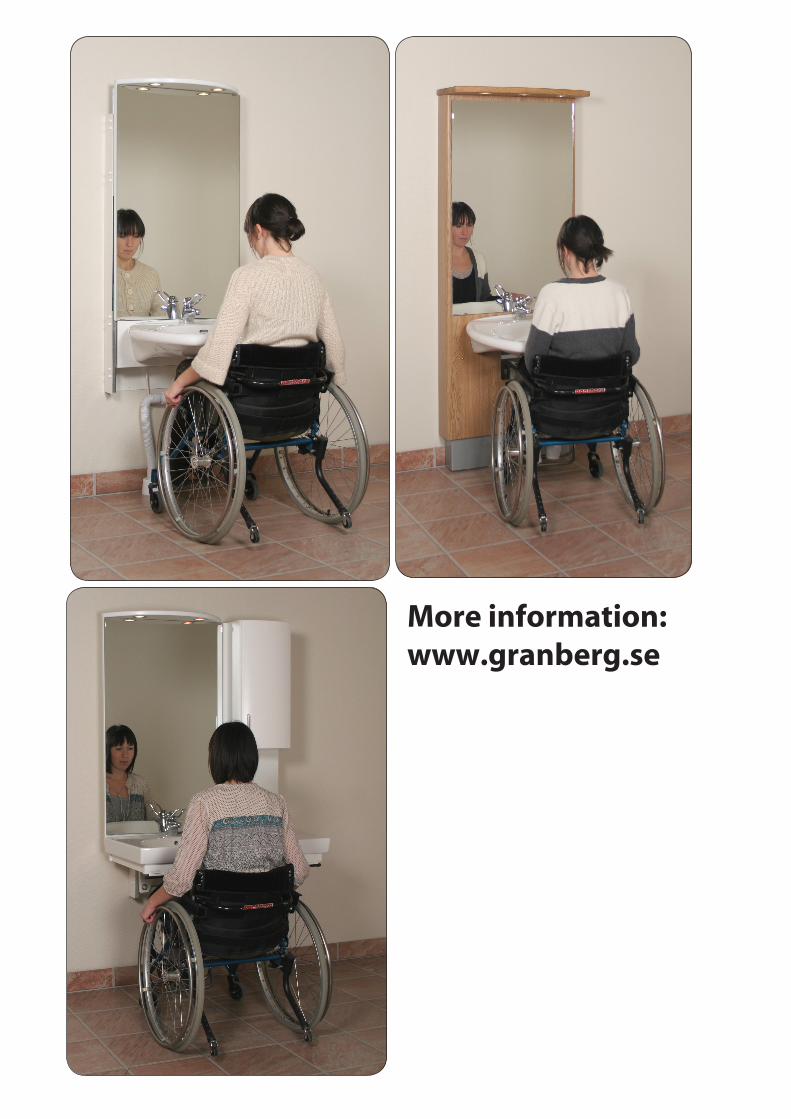
4140 Motorised washbasin lift with counter top beside basin. A safety switch in the form of a safety buffer underneath the washbasin is included in the basic design.
When the height is adjusted, the mirror lighting and bathroom cabinet move with the basin. Free space beneath lift for installation of water pipe and drain.
4170 Neatly designed motorised washbasin lift. Rounded installation panel in laminate.
When the height is adjusted, the mirror and spotlight fitting move with the basin The water and drain hoses are elegantly concealed behind a casing.
4130 Motorised washbasin lift. When the height is adjusted, the mirror and spotlight fitting move with the basin. Free space beneath lift for installation of water pipe and drain.
1. Introduction
We have the pleasure to deliver a Granberg Interior Washbasin lift, an electrically operated lifting and lowering system for new or existing washbasins without cabinets under the washbasin. The main models are:
The various models can be furnished with a wide range of washbasins, in accordance with our leaflets. Other washbasin makes can have different design, so that they do not fit regarding attachment arrangements, weight and dimensions. We disclaim all responsibility if other models than those approved by us are used.
Only authorized persons may use the Washbasin lift!
Authorization means obligation to read and follow the instructions.
It is very important that you read and understands the instructions before you use the device. If you have any questions - contact your supplier.
This Instruction manual shall be available for all concerned persons, be kept in a protected place and shall follow the product, if it is moved to another installation site or another house or apartment owner.
Correct use, operation, inspections and maintenance are decisive for efficient and safe work.

�
Model: 4130 4140 4170
Width of the back panel 600 mm 920 mm 700 mm
Washbasin height, adjustable 650-900 mm 650-900 mm 650-900 mm
Total depth from the wall * 115 mm * 640 mm 120 mm *
Vertical stroke, max 250 mm 250 mm 250 mm
Time for a lift or lowering stroke, approx 18 mm / s 18 mm / s 18 mm / s
Overall height 1925 mm 1975 mm 2015 mm
Mains supply 230 V 230 V 230 V
Power consumption 160 W 160 W 160 W
Max no. of full work cycles per hour 6 6 6
Control voltage 24 V DC 24 V DC 24 V DC
Lighting voltage 230 V 230 V 230 V
Weight incl. washbasin, maximum size 60 KG 80 KG 80 KG
Max load on the washbasin 40 KG 20 KG 40 KG
The noise pressure is less than 70 db(A) 70 db(A) 70 db(A)
* The measure refers from the wall to the front of the mounting plate excluding safety switch, 36 mm. (Washbasin is not included)
2. Declaration of Conformity with EU-directives
This product is CE-marked and is granted to conform to the basic safety and operation requirements, in accordance with de actual Machinery, EMC- and Low voltage Directives. A separate “CE-Declaration of Conformity” is available in section 18.
3. Intended use - Technical data
The Washbasin lift 4130 / 4140 / 4170 is intended to vertically lift and lower a washbasin and sometimes even a mirror and lighting to a convenient level. The operation shall be indoors under normal housing conditions regarding temperature, humidity and lighting.
The Washbasin lift, which has electric protection class IP 54, is made for use in humid rooms, but not for rinsing and flush-ing with water. The hand control unit with spiral cable has protection class IP 65.
It is absolutely forbidden for persons to stay on the washbasin, or to use it for lifting persons. It is also not allowed to use the lift as a support when a person rises up.

�
Kortling (Centrum)
Alt. Kortling (Centrum)
Alt. Kortling (Centrum)
Kortling (Centrum)
1620
550
480
1550
(mm)
4.1 Preparations - Joist heights for Washbasin lifts 4130 / 4140 / 4170
The models 4130, 4140 and 4170 have all the same lifting mechanism. Different equipment is mounted at the lifting mechanism depending on which model it is.
Follow the instructions in the manual for correct installation of the washbasin lift.
Laying joists in the wall shall be positioned acc. the following dimensions.
The installation technician is responsible for that sufficient method and dimensions are used for the installation on the wall. The wall properties, such as porosities, and the type of attachment components will be decisive for the re-quirements. Be aware of that the Washbasin lift can have an overall weight of more than 130 kg plus dynamic effects from the motions.
Joist (Centre measure)
Alternative Joist (Centre measure)
Joist (Centre measure)
Alternative Joist (Centre measure)

7
550 69
0 790
1123
1550
1223
209
175
209
Centrum
(mm)
450
580
(mm)Professionals must make the connection of the water and sewer pipes to prevent water damages.
It is important that the right materials are used, and that location and fixing is made properly. - The use of Granberg original installation materials, and the instructions in this manual, ensures correct execution, if a competent fitter carries out the installation work. - The water connection shall be made to a lockable coupling. - The connection at the drain hose is 40 mm.
- Recommended location of the sewerage: Within the grey zone acc. picture to the right.
Water and sewerage installation in the wall under the lifting mechanism: Recommended position is about 200 mm over the floor. (Thisensuregoodoutflowandminimalriskofcollisionwiththeusersfeet.) Notice! Model 4170 has a limited space for installation (90 mm in depth) .
Notice!Consider the applicable rules for electric installations in bathrooms. Always connect an earth leakage protection device in the motor feed circuit.
An authorized electrician must make the electric installation!
Electric connections to the washbasin lift: The Washbasin lift must be connected to a separate mains switch, which is placed in the bathroom or its vicinity.
Electric connection to the lightning: Connect the lightning to a switch near to the Wash-basin lift or connect it to the switch that activates the lightning to the room. Recommended location of the electric connections: Within the grey zone acc. picture to the right.
4.2 Preparations - Installation of sewerage and electric connections
Cen
tre

�
0 m
m54
�.1 General information - mounting on the wall
Competent persons must make the installation work!
The installation technician is responsible for that sufficient method and dimensions are used for the installation on the wall. The wall properties, such as porosities, and the type of attachment components will be decisive for the requirements. Be aware of that the Washbasin lift can have an overall weight of more than 130 kg plus dynamic effects from the motions.
Handle the Washbasin lift and the accessories with sufficient lifting arrangements, considering ergonomic principles.
Distance plate
Notice!- Check that the wall is flat and vertical. - There shall be a space of 50 mm between the Washbasin lift and adjacent walls or cabinet sides.- Check that the wall is strong enough for mounting, e.g. joists in the correct positions.
(See section 4.1)
1. Unpack the lifting mechanism and place it at the floor.
2. Connect the electric cable to a power socket and run the lifting mechanism to its top position.
3. Place the distance plate (for correct height position) at the floor close to the wall.
4. Place the lifting mechanism at the distance plate. Check with a spirit level that the lifting mechanism is in correct vertical position. Fasten the mounting screws in the wall.
5. Continue to correct section for further mounting for the model that you have chosen: Model 4130 - Page 9 Model 4140 - Page 13 Model 4170 - Page 16
�
U
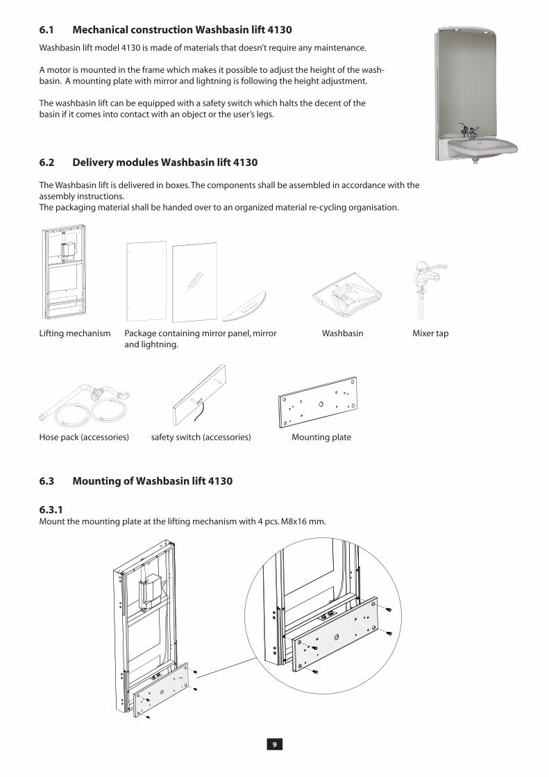
�.1 Mechanical construction Washbasin lift 4130
�.2 Delivery modules Washbasin lift 4130
The Washbasin lift is delivered in boxes. The components shall be assembled in accordance with the assembly instructions.The packaging material shall be handed over to an organized material re-cycling organisation.
Lifting mechanism
Hose pack (accessories)
Package containing mirror panel, mirror and lightning.
Washbasin Mixer tap
safety switch (accessories)
�.3 Mounting of Washbasin lift 4130
Mounting plate
�.3.1Mount the mounting plate at the lifting mechanism with 4 pcs. M8x16 mm.
Washbasin lift model 4130 is made of materials that doesn’t require any maintenance. A motor is mounted in the frame which makes it possible to adjust the height of the wash-basin. A mounting plate with mirror and lightning is following the height adjustment. The washbasin lift can be equipped with a safety switch which halts the decent of the basin if it comes into contact with an object or the user’s legs.

10
�.3.2 Connect and mount the safety switch (accessories)
Connection:Push the cable through the mounting plate (see picture 1). Connect the cable as shown at picture 2. (You have to run the lifting mechanism upwards to see the connections)
MountingPush the bolts through the mounting plate and tighten with the screw nuts from the back. 2 pcs. screw nuts M12 + 2 pcs. screw nuts M6.
�.3.3Mount the panel for the lightning at the top of the mirror panel by using 2 screws. Mount the mirror panel at the lifting mechanism. Se section 4.2 for connection of the lightning.
Picture 1 Picture 2

11
�.3.4Mount the washbasin at the bolts. Lock with 2 screw nuts M12.
If the washbasin lift is not equipped with safety switch: Mount the washbasin by the use of 2 ocs M12 bolts through the mounting plate. Bolts are included in the delivery.
�.3.�Mount the mirror in the desired height position by the use of enclosed mirror fittings.
�.3.�Mount the mixer tap
�.3.7Mount the loops that works as a fixture for the drain hose. 2 loops M6 with screw nuts.
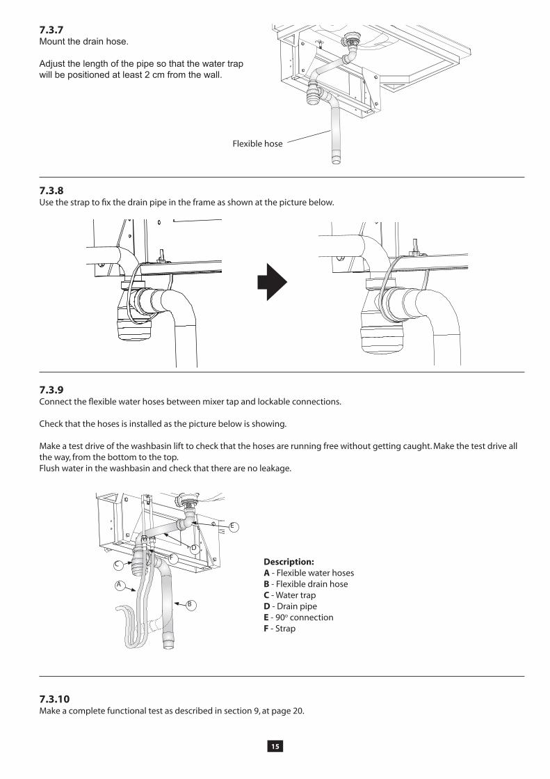
�.3.�Mount the drain hose.
Adjust the length of the pipe so that the water trap will be positioned at least 2 cm from the wall.
Flexible hose

12
B A
D
C
EF
�.3.�Fix the drain pipe through the loops with the strap.
�.3.10Connect the flexible water hoses between mixer tap and lockable connections. Check that the hoses is installed as the picture below is showing.
Make a test drive of the washbasin lift to check that the hoses are running free without getting caught. Make the test drive all the way, from the bottom to the top. Flush water in the washbasin and check that there are no leakage.
�.3.11Make a complete functional test as described in section 9, at page 20.
Description:A - Flexible water hoses B - Flexible drain hoseC - Water trapD - Drain pipeE - 90o connection F - Strap

13
U
Hose pack (accessories)
Mounting plateFrame for washbasin
Cabinet (accessories)
7.1 Mechanical construction Washbasin lift 4140
7.2 Delivery modules Washbasin lift 4140
The Washbasin lift is delivered in boxes. The components shall be assembled in accordance with the assembly instructions.The packaging material shall be handed over to an organized material re-cycling organisation.
Lifting mechanism
Washbasin lift model 4130 is made of materials that doesn’t require any maintenance. A motor is mounted in the frame which makes it possible to adjust the height of the washbasin. A mounting plate with mirror, cabinet and lightning is following the height adjustment. This model has a safety strip as standard.
Lightning and mirror (accessories)

14
SILIKON
7.3.�Apply silicone in the small opening between the rear edge of the washbasin and the mounting plate.
7.3 Mounting of Washbasin lift 4140
7.3.1Mount the rame for the washbasin. Use the enclosed bolts M8 x 50 mm.Connect the cabel of the safety strip as shown in the picture below.
7.3.3Connect the lightning to a power socket and mount the mounting plate at the lifting mechanism. Notice! Check that the cable is long enough for the movement of the mechanism (250 mm). Make a test drive to check.
7.3.4The washbasin is fixed to the frame with glue. The rear edge of the washbasin shall be placed as near as possible to the mounting plate.
7.3.2Mount the lightning (accessories) at the top of the mount-ing plate. the mounting plate is prepared with two holes.
7.3.�Mount the cabinet, mirror and mixer tap.
1�
C
A
B
FD
E
7.3.�Use the strap to fix the drain pipe in the frame as shown at the picture below.
7.3.7Mount the drain hose.
Adjust the length of the pipe so that the water trap will be positioned at least 2 cm from the wall.
7.3.�Connect the flexible water hoses between mixer tap and lockable connections. Check that the hoses is installed as the picture below is showing.
Make a test drive of the washbasin lift to check that the hoses are running free without getting caught. Make the test drive all the way, from the bottom to the top. Flush water in the washbasin and check that there are no leakage.
7.3.10Make a complete functional test as described in section 9, at page 20.
Description:A - Flexible water hoses B - Flexible drain hoseC - Water trapD - Drain pipeE - 90o connection F - Strap
Flexible hose

1�
U
�.1 Mechanical construction Washbasin lift 4170
�.2 Delivery modules Washbasin lift 4130
The Washbasin lift is delivered in boxes. The components shall be assembled in accordance with the assembly instructions.The packaging material shall be handed over to an organized material re-cycling organisation.
Washbasin lift model 4170 is made of materials that doesn’t require any maintenance. A motor is mounted in the frame which makes it possible to adjust the height of the wash-basin. A mounting plate with mirror and lightning is following the height adjustment.
The washbasin lift can be equipped with a safety switch which halts the decent of the basin if it comes into contact with an object or the user’s legs.
Lifting mechanism Package containing mounting plate, mirror and lightning.
Washbasin Mixer tap
Hose pack (accessories) Cover plate (in front of hoses) Mounting plate
17
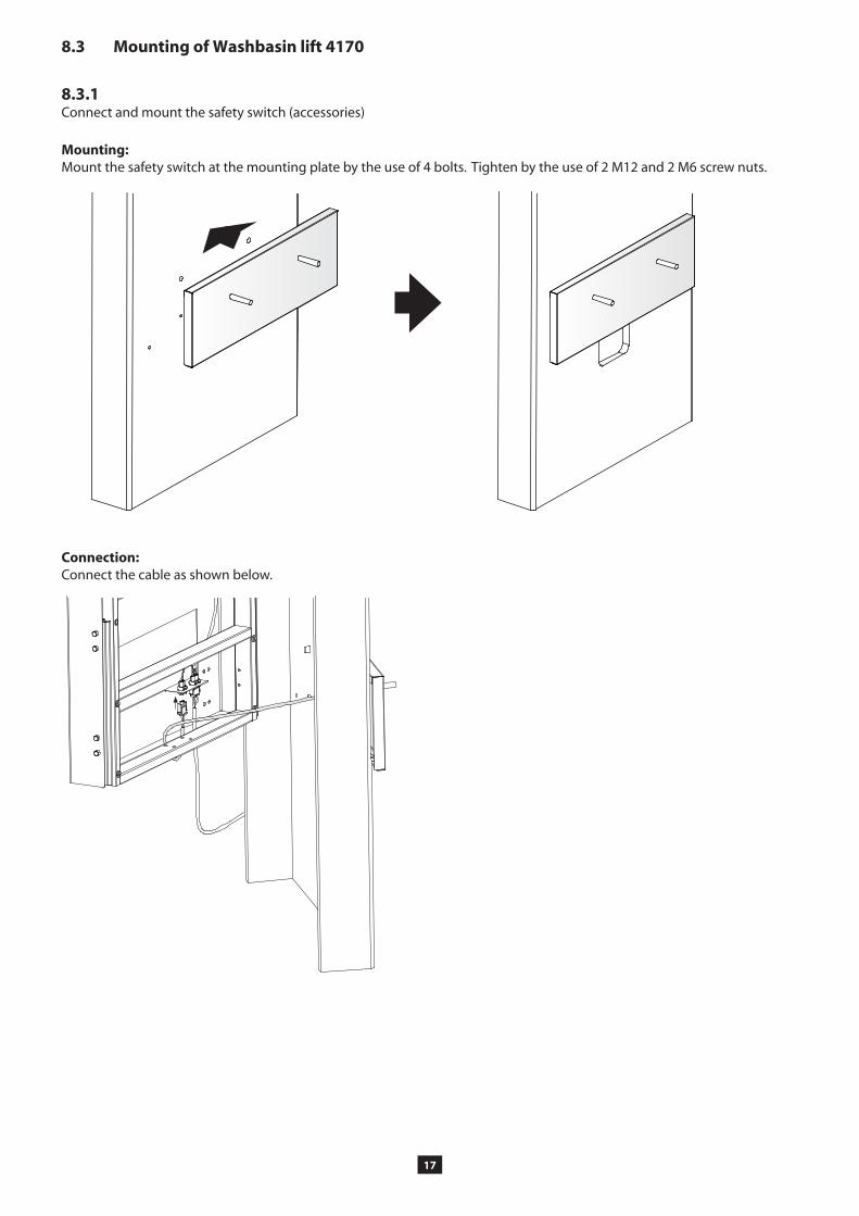
Mounting:Mount the safety switch at the mounting plate by the use of 4 bolts. Tighten by the use of 2 M12 and 2 M6 screw nuts.
�.3 Mounting of Washbasin lift 4170
�.3.1Connect and mount the safety switch (accessories)
Connection:Connect the cable as shown below.
1�
a
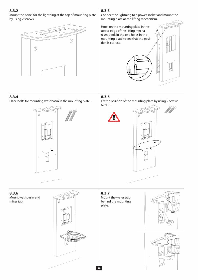
�.3.2Mount the panel for the lightning at the top of mounting plate by using 2 screws.
�.3.3Connect the lightning to a power socket and mount the mounting plate at the lifting mechanism.
Hook on the mounting plate in the upper edge of the lifting mecha-nism. Look in the two holes in the mounting plate to see that the posi-tion is correct.
�.3.4Place bolts for mounting washbasin in the mounting plate.
�.3.�Fix the position of the mounting plate by using 2 screws M6x35.
�.3.�Mount washbasin and mixer tap.
�.3.7Mount the water trap behind the mounting plate.
1�
B
A
D
E
C
It is possible to make holes in the hose cover if water tubes are coming from the side Notice! The upper edge of the holes must not be place over 70 mm from the floor.
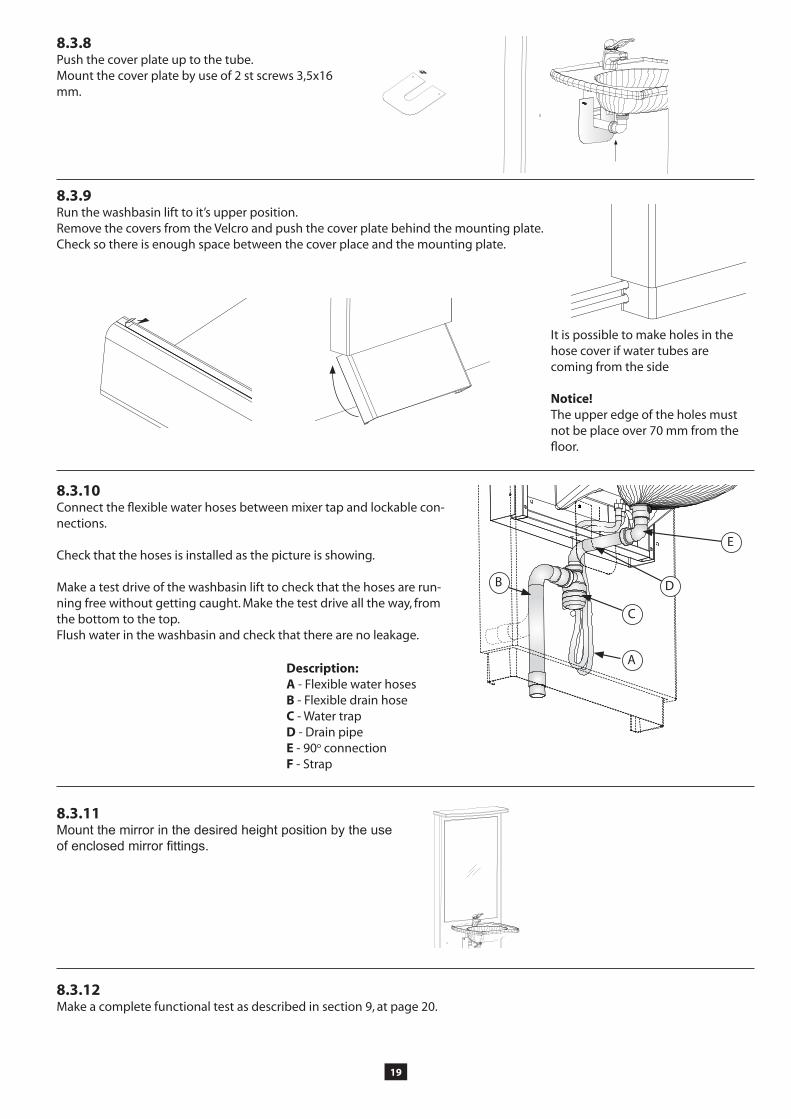
�.3.10Connect the flexible water hoses between mixer tap and lockable con-nections. Check that the hoses is installed as the picture is showing.
Make a test drive of the washbasin lift to check that the hoses are run-ning free without getting caught. Make the test drive all the way, from the bottom to the top. Flush water in the washbasin and check that there are no leakage.
�.3.11Mount the mirror in the desired height position by the use of enclosed mirror fittings.
�.3.12Make a complete functional test as described in section 9, at page 20.
Description:A - Flexible water hoses B - Flexible drain hoseC - Water trapD - Drain pipeE - 90o connection F - Strap
�.3.�Push the cover plate up to the tube. Mount the cover plate by use of 2 st screws 3,5x16 mm.
�.3.�Run the washbasin lift to it’s upper position. Remove the covers from the Velcro and push the cover plate behind the mounting plate. Check so there is enough space between the cover place and the mounting plate.
20
�. Functional test
After installation a complete functional test with full load shall be made: Run the Washbasin lift down and up all the way to respectively end position. Check that it moves freely, without hindrance and jarring sounds. Check that no cables or hoses are jammed and that the water and sewer hoses are properly fixed to the wall.
Notice! Raise the lift to the end position to check that the hoses are long enough.
10.1 Safe use
The Washbasin lift is provided with safety arrangements in order to prevent and avoid damages and accidents. It is however still very important that the operator is well instructed in how to install and operate the Washbasin lift. In the following the Washbasin lift means the lifting machine and the fitted washbasin and possible mirror.
• Only use the Washbasin lift for its intended purpose. (See section 3).• The operation and use must be made in such way that there is no risk for damages on persons and property.• The Washbasin lift may only be operated by persons who have read and understood these instructions, and are
authorized to use it.• Be aware of that you as an operator are responsible for that nobody is damaged.• The Washbasin lift and the work area must be in proper condition. The Washbasin lift must not be used if any fault
has appeared which influences the functions or the operation safety. It shall also not be used if it has been repaired, altered or adjusted without permission of a responsible person.
• Make sure that the Washbasin lift is installed on a firm, flat and absolutely vertical wall with sufficient mounting details, enough for the total weight incl. the washbasin, its content, mirror and objects on it. • The operator shall have a clear view of the hazardous parts of the Washbasin lift and the area around it all the time
when operations are taking place.• Do not touch any part of the lift when operating it. Only press the button for desired motion direction.• Do not put hands, arms, or any other part of the body or any object under the washbasin when the lift is operated.• If the mirror is placed behind the lift particular attention must be paid to the risk for collision between the top shelf
and the bottom edge of the mirror. (Only applicable to model 807)• Note! Jamming risk between the Washbasin lift and adjacent cabinets and benches.• Only stable and securely loaded items may be handled. Mind the tilting risk for objects on the washbasin or shelf,
which are unstable, e.g. carelessly piled. If the washbasin is tilt able there is a big risk that objects are tipping over or water from the washbasin will flow out.
• Never let the Washbasin lift touch any adjacent objects. • Alterations of the Washbasin lift that influence the operational safety or the functions are not allowed.• Decals and markings must not be removed or made illegible.• Do not overload the Washbasin lift and make sure that the load distribution is correct.• It is absolutely forbidden for persons to stay on the washbasin or to use the lift for lifting persons. It is also not allowed
to use the lift as a support when a person rises up. • Use safe and sufficient lifting methods when handling load to and from the Washbasin lift. In particular beware when
handling heavy items, and goods with hazardous content or with sharp corners and edges.• The Washbasin lift shall regularly, once a year, be inspected in order to prevent accidents.• Applicable Building and Safe use Regulations must be complied with.• Do not use the Washbasin lift as a lifting jack, e.g. for lifting things from the floor.• The machine shall no be in direct contact with food.• Do not use the Washbasin lift in a potentially explosive environment.• When the operation is in a public location, particularly when children can enter the work area, the operator shall make
satisfactory arrangements to prevent persons from entering the hazardous area when the lift is being operated, or it has been lowered from the parking position, e.g. by means of blocking the work area or by means of adding protection devices.• During inspections, service and repair work there shall be no load on the washbasin lift. The most common functions is reached behind the mounting plate. • Competent persons only must carry out installation, service and repair works.• Only Granberg original spare parts shall be used when replacing any parts. Our warranty commitment can otherwise
be invalidated.
21
10.4 Control device options
As standard the lift is supplied with a push button box with a spiral cable, to be kept by hand when operating the lift. The box can be parked in a convenient place, e.g. hanging on the washbasin edge.
10.3 Actions after use
The Washbasin lift shall after use be left in its current position. Switch off the main switch and lock it in closed position, if unauthorized use can occur.To prevent unauthorized use can it is also possible to place the control device in a lockable cabinet.
10.2 Load distribution and side forces
Basic loading requirements:* 100 % of the rated load distributed over the entire washbasin surface, with the centre of gravity at the washbasin top.* Horizontal forces are not allowed.
Horizontal forces can appear, for example, when pressing onto the Washbasin. It is difficult to estimate the size of the actual horizontal force, so utmost care must always be taken. Further to the incorporated safety arrangements additional can safety actions may be required on or at the Washbasin lift. Discuss suitable actions with your Granberg representative or with the health and safety inspection.
We recommend that a Risk assessment in accordance with the Machinery Directive shall be made for the actual working con-ditions.If the owner fits accessories, contact Granberg to get approval for the loading conditions.
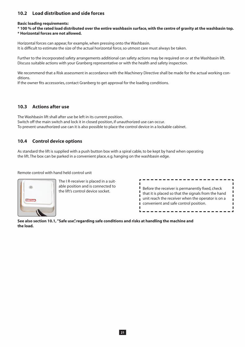
Remote control with hand held control unit
Before the receiver is permanently fixed, check that it is placed so that the signals from the hand unit reach the receiver when the operator is on a convenient and safe control position.
See also section 10.1, ”Safe use”, regarding safe conditions and risks at handling the machine and the load.
The I R-receiver is placed in a suit-able position and is connected to the lift’s control device socket.

22
10.� Cleaning
In its use in a bathroom environment the mechanism can be exposed to dirt. As the Washbasin lift contains electrical compo-nents it is very important that cleaning is made according this instruction.
WARNING!* The Washbasin lift must absolutely not be connected to the electric supply when cleaning is carried out.* The Washbasin lift must absolutely not be rinsed with water! (Not applicable for the washbasin).
Care instructions:Clean with lukewarm water and a non-scratching detergent containing soap or similar. Use a Wettex swab or similar. After cleaning the surfaces shall be dried to avoid lime deposits. Scratching detergents or tools e.g. steel wool may not be used.The Washbasin, mirror and other equipment shall be cleaned and maintained acc. to the manufacturers instructions.
10.� Maintenance
The Washbasin lift is maintenance-free. Greasing and other actions are made during the manufacturing for the lifetime of the lift. From safety point of view however some components shall be inspected each year.
* Inspections, service and repair work shall be made by competent persons.* Remove any objects from the washbasin before maintenance and repair works are made.
1. Run the lift down and up all the way to respective end position. Check that it runs freely without trapping risks and jarring sounds. Check that it stops and stays in the lower respective upper positions.
2. Check that the cables are not chafed, squeezed or breaking and that there is no risk for damages.
3. Check that the wall-, washbasin- and mirror attachments are in proper order. If the machine is inclined adjustment can be made according to the installation instructions.
Accomplished inspections and repair works shall be specified in the service records in section 14.

23
40 kg
When the Washbasin lift is reused make sure that safety trip panel is the right size.
We recommend the machine to be sent to Granberg or to the Granberg distributor to get this done.
The machine is manufactured from re-usable materials or from materials that can be recycled.
11. Instructions for recycling
12. Decals
Two decals are included in the instruction manual envelope, and these must be placed on the washbasin in full view for the user.
13. Warranty
In accordance with the warranty conditions Orgalime S 2000 the manufacturer will replace or repair all faults which depend on manufacturing or material faults and which appear within twenty-four (24) months from the delivery. For further details about the conditions, see Orgalime S 2000. Note! Alternative warranty conditions may apply. See the Order Acknowledgement for actual conditions.
The warranty is only valid if inspections and maintenance is carried out in accordance with the instructions. This warranty does not cover the cost of normal maintenance, settings or scheduled adjustments as specified in the instructions. Also the labour costs for such actions are not covered by the warranty
Damages caused by misuse or incorrect operation of the equipment means that the warranty would expire.
Before any warranty work is commenced by a customer Granberg must be contacted for analysis and approval. We do not ac-cept to carry any warranty costs if the repair work has started without an agreement by us.
When returning parts always quote the details shown on the manufacturer’s plate, i.e. Type, manufacturing number, year and describe the operating conditions for the machine.
Remember to quote name, address and telephone number for the appropriate contact person.

24
14. Service and Maintenance Records
Type and model:_______________________ Manufacturing No.:________________________
Delivery date:_____________________________
Service & maintenance
Date:______________________ Sign._______________________ Remarks:___________________ ___________________________ ___________________________ ___________________________
Service & maintenance
Date:______________________ Sign._______________________ Remarks:___________________ ___________________________ ___________________________ ___________________________
Service & maintenance
Date:______________________ Sign._______________________ Remarks:___________________ ___________________________ ___________________________ ___________________________
Service & maintenance
Date:______________________ Sign._______________________ Remarks:___________________ ___________________________ ___________________________ ___________________________
Service & maintenance
Date:______________________ Sign._______________________ Remarks:___________________ ___________________________ ___________________________ ___________________________
Service & maintenance
Date:______________________ Sign._______________________ Remarks:___________________ ___________________________ ___________________________ ___________________________
Service & maintenance
Date:______________________ Sign._______________________ Remarks:___________________ ___________________________ ___________________________ ___________________________
Service & maintenance
Date:______________________ Sign._______________________ Remarks:___________________ ___________________________ ___________________________ ___________________________
Service & maintenance
Date:______________________ Sign._______________________ Remarks:___________________ ___________________________ ___________________________ ___________________________

2�
1
23
1�. Fault finding
The Washbasin lift is designed and tested to achieve optimum operation reliability and long life, provided that the operation, maintenance and inspections are carried out in accordance with the prescribed instructions. If in spite of this a fault appears you can get guidance about what to do according to the fault finding list below.
Remove the load from the basin before fault finding and repair work is carried out.Fault finding, service and repair work shall made by competent persons only.
If any problem remains after you have taken actions in accordance with the list below you must contact a competent techni-cian or you supplier.
Problem Actions
The Washbasin lift does not move when a control signal is given
Check that the fuse for the mains feed is not damaged
Check that the mains plug is connected.
Take off the mounting plate to reach the motor and control box. Check that the green light on the control box is lightning. This indicates that there is power to the control box.
If the lift still does not move contact an authorized technician and/or your supplier. This shall as first action, after above check points, check that all cables are connected and undamaged, and that the green light on the control box is lighting.
If it is not lighting the control box is probably defect. Order a new unit from Granberg.
The safety switch is not working (accessories) Check that the cable from the safety switch is connected.
If the lifting mechanism doesn’t move after the steps above, contact your supplier.
1�. Spare parts list
If any component does not work or has broken, contact your supplier. Only Granberg original spare parts must be used when replacing any parts. Our warranty commitment may otherwise be invalidated.
Pos: Description:1 Motor2 Control box3 Push button device with spiral cable
Return of spare parts:Contact Granberg prior to any return of parts. Do not return any parts that have been worn out during normal operation or accidentally damaged. Only return worn or dam-aged parts if it is considered that the fault is covered by our warranty conditions. In such cases, return the parts without delay, otherwise the right to replacement may be lost.
When ordering spare parts always quote the manufacturing number and type.
When repair work has been carried out on the Washbasin lift a complete functional test with full load shall be made, before it is taken into use. (See section 9.)

2�
Safety switch (accessories)
17. Electric system

27
(According Machinery Directive 98/37/EC, Annexe 2A)
Manufacturer: Granberg Interior AB Box 6112, SE-600 06 NORRKÖPING, Sweden Tel. +46-11-19 77 50 Fax +46-11-12 76 76
declares under sole responsibility that the product:
to which this declaration relates, is in manufactured in conformity with the following harmonised documents,
following the provisions of Machinery Directive 98/37/EC, the Low Voltage Directive 73/23/and the EMC Directive 89/336/EEC
It also conforms to the following harmonised standards:
EN 60204-1 Safety of Machinery - Electrical Equipment of Machines -General Requirements
Norrköping, 2008-05-06Granberg Interior AB
Tobias GranbergManaging Director
1�. CE-DECLARATION OF CONFORMITY
Space for machine plate

Box 6112 SE-600 06, Norrköping SwedenTel: +46 (0)11-19 77 50 Fax: +46 (0)11-12 76 76
E-mail: [email protected] - Internet: www.granberg.se


![Read the words : [w] wall washbasin wardrobe window [ei] table bookcase washbasin painting.](https://static.fdocuments.us/doc/165x107/56649f4f5503460f94c71339/read-the-words-w-wall-washbasin-wardrobe-window-ei-table-bookcase-washbasin.jpg)