Instruction Manual - SquarespaceManual.pdf · 15 POWER PROBE WARRANTY ... recommends reading this...
30
www.powerprobe.com • 800-655-3585 Power Probe Basic 1 English Español www.powerprobe.com Power Probe Basic Power Probe Basic The Ultimate in Circuit Testing Instruction Manual Manual de Instrucciones
Transcript of Instruction Manual - SquarespaceManual.pdf · 15 POWER PROBE WARRANTY ... recommends reading this...

www.powerprobe.com • 800-655-3585
Power Probe Basic 1
English
Español
www.powerprobe.com
Power Probe BasicPower Probe Basic
The Ultimate in Circuit Testing
InstructionManual
Manual de Instrucciones
www.powerprobe.com • 800-655-3585
Power Probe Basic 2
INTRODUCTION ..........................................................................3
WARNING ................................................................................... 3
SAFETY ......................................................................................... 4
FEATURES .....................................................................................5
HOOK-UP .................................................................................... 6
QUICK SELF-TEST .........................................................................6
POLARITY TESTING ...................................................................... 7
CONTINUITY TESTING ................................................................. 8
ACTIVATING REMOVED COMPONENTS ................................... 9
TESTING TRAILER LIGHTS AND CONNECTIONS ......................10
POWER TESTING A GROUND ................................................. 11
ACTIVATING ELECTRICAL COMPONENTS WITH
POSITIVE (+) VOLTAGE ..........................................................12
GROUND SWITCHING A CIRCUIT HAVING AN
ELECTRICAL LOAD ................................................................13
REPLACING OLD ROCKER SWITCH ........................................ 14
ATTACHING THE SWITCH LATCH .............................................. 14
FOLLOWING AND LOCATING SHORT CIRCUITS ................... 15
POWER PROBE WARRANTY ..................................................... 15
ENGLISH
TABLE OF CONTENTS

www.powerprobe.com • 800-655-3585
Power Probe Basic 3
INTRODUCTIONThank you for purchasing the Power Probe Basic. It’s your best value for testing automotive electrical problems.
After connecting it to the vehicle’s battery you can now see if a circuit is Positive, Negative or Open by probing it and observing the RED or GREEN LED. You can quickly activate electric components with the press of the power switch and YES, its short circuit protected. Continuity of switches, relays, diodes, fuses and wires are easily tested by connecting them between the auxiliary ground lead and the probe tip and observing the GREEN LED. Check fuses and test for short circuits. Find faulty ground connections instantly. The 20 ft. long lead will reach from bumper to bumper and it has the option to connect a 20 foot extension lead to make it reach up to 40 feet. Great for trucks, trailers and motorhomes. If you are not using a Power Probe in your electrical testing, you are wasting time.
Before using the Power Probe Basic, please read the instruction book carefully.
When the Power Switch is depressed battery current is conducted directly to the tip which may cause sparks when contacting ground or certain circuits. Therefore the Power Probe should NOT be used around flammables such as gasoline or its vapors. The spark of an energized Power Probe could ignite these vapors. Use the same caution as you would when using an arc welder.
The Power Probe Basic is NOT designed to be used with 110/220 AC-volt house current, it is only for use with 6-12 VDC systems.
WARNING!

www.powerprobe.com • 800-655-3585
Power Probe Basic 4
SAFETY
Caution - Please Read
Do not connect to electrical system with higher than rated volt-age specified in this manual.
Do not test voltage exceeding the rated voltage on the Power Probe Basic.
Check the PP Basic for cracks or damage. Damage to the case can leak high voltage causing a potential electrocution risk.
Check the PP Basic for any insulation damage or bare wires. If damaged, do not use the tool, please contact Power Probe Technical support.
Use only shrouded leads and accessories authorized by Power Probe to minimize exposed conductive electrical connections to eliminate shock hazard.
Do not attempt to open the PP Basic, no serviceable parts are inside. Opening this unit voids the warranty. All repairs should only be performed by authorized Power Probe service centers.
When maintaining the Power Probe, use only replacement parts certified by the manufacturer.
Use only in well ventilated areas. Do not operate around flamma-ble materials, vapor or dust.
Be careful when energizing components that have moving parts, assemblies containing motors or high powered solenoids.
Power Probe, Inc. shall not be liable for damage to vehicles or components cause by misuse, tampering or accident.
Power Probe, Inc. shall not be liable for any harm caused by accidents, intentional misuse of our products or tools.
If you have any questions, please go to our website at: www.powerprobe.com or contact our Technical Support at: 800-655-3585.
To avoid possible electric shock or personal injury and to avoid damage to this unit, please use the Power Probe Basic according to the following safety procedures. Power Probe recommends reading this manual before using the Power Probe Basic.
The Power Probe BASIC is strictly designed for automotive electrical systems. It is to be used on 6 to 12 volt DC only. The power switch should not be pressed when connected to electronic control modules, sensors or any sensitive electronic components. DO NOT connect the Power Probe to AC house electrical such as 115 Volts.

www.powerprobe.com • 800-655-3585
Power Probe Basic 5
Probe Tip
LEDGreen
LEDRed
RockerSwitch
BatteryClips
Heavy-Duty 4mm Male/
Female Keyed Connectors
20 ft.Power Lead
FEATURES
6 -12 VOLTS
Switch Latch(Included)
AuxilliaryGround
Lead

www.powerprobe.com • 800-655-3585
Power Probe Basic 6
HOOK-UP
QUICK SELF-TEST
Unroll the Power Cable.Attach the RED battery hook-up clip to the POSITIVE terminal of the vehicle’s battery.Attach the BLACK battery hook-up clip to the NEGATIVE terminal of the vehicle’s battery.
Rock the power switch forward (+), the LED indicator should light RED.Rock the power switch rearward (-), the LED indicator should light GREEN.The Power Probe is now ready to use.
6 -12 VOLTS
BATTERY
Red LED
Green LED
Forward Position
Rearward Position

www.powerprobe.com • 800-655-3585
Power Probe Basic 7
POLARITY TESTINGBy contacting the Power Probe tip to a POSITIVE (+), circuit will light the LED indicator RED. By contacting the Power Probe tip to a NEGATIVE (-), circuit will light the LED indicator GREEN.By contacting the Power Probe tip to an OPEN, circuit will be indi-cated by the LED indicator not lighting.
Red LED = Positive
Green LED = Negative
6 -12 VOLTS
BATTERY
BATTERY
6 -12 VOLTS
www.powerprobe.com • 800-655-3585
Power Probe Basic 8
CONTINUITY TESTING
Continuity Testing Application
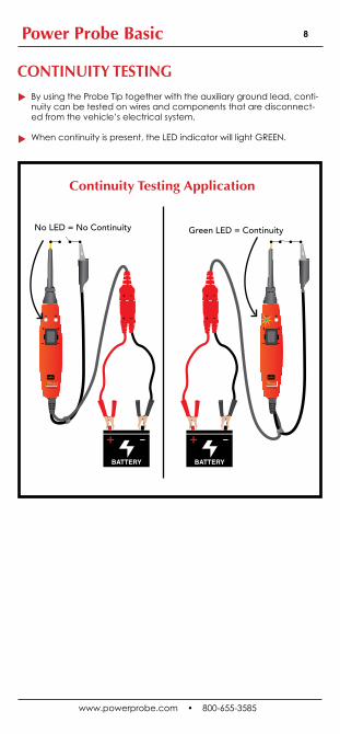
By using the Probe Tip together with the auxiliary ground lead, conti-nuity can be tested on wires and components that are disconnect-ed from the vehicle’s electrical system.
When continuity is present, the LED indicator will light GREEN.
6 -12 VOLTS
BATTERY BATTERY
6 -12 VOLTS
No LED = No Continuity Green LED = Continuity

www.powerprobe.com • 800-655-3585
Power Probe Basic 9
ACTIVATING REMOVED COMPONENTSBy using the Power Probe tip together with the auxiliary ground lead, components can be activated, thereby testing their function.Connect the negative auxiliary clip to the negative terminal of the component being tested.Contact the probe to the positive terminal of the component, the LED indicator should light GREEN indicating continuity through the component.While keeping an eye on the green LED indicator, quickly depress and release the power switch forward (+). If the green indicator changed instantly from GREEN to RED you may proceed with further activation. If the green indicator went off at that instant or if the circuit breaker tripped, the Power Probe has been overloaded. This could happen for the following reasons:• The contact is a direct ground or negative voltage.• The component is short-circuited.• The component is a high amperage component (i.e., starter motor).If the circuit breaker is tripped, it’ll automatically reset to default position.
6 -12 VOLTS
BATTERY
Connect thenegative auxiliary clip to bulb casing
Contact the tip to the positive
terminal of the bulb
Press the power switch forward to activate
the bulb
Other than light bulbs, you can also activate other components like fuel pumps, window
motors, starter solenoids, cooling fans, blowers, motors, etc.

www.powerprobe.com • 800-655-3585
Power Probe Basic 10
BATTERY
6 -12 VOLTS
TESTING TRAILER LIGHTS AND CONNECTIONS
1. Connect the Power Probe Basic to a good battery.2. Clip the auxiliary ground clip to the trailer ground.3. Probe the contacts at the jack and apply voltage to them. This lets you check the function and location of the trailer lights. If the circuit breaker tripped, it’ll automatically reset after it cools.
• Identify which terminal illuminates specific lights• Finds shorted wires• Shows open or broken wires
8 Amps = No Trip10 Amps = 20 sec.15 Amps = 6 sec.25 Amps = 2 sec.Short Circuit = 0.3 sec.
BREAKER TRIP RESPONSE SPECIFICATIONS

www.powerprobe.com • 800-655-3585
Power Probe Basic 11
BATTERY
6 -12 VOLTS
BATTERY
6 -12 VOLTS
Red LED DOES NOT Light
Red LED Lights On
Resistance inGround Feed
CircuitBreaker Trips
Circuit BreakerDoes NOT Trip
First be sure the ground feed you are testing is really a ground feed. Do NOT activate electronic control circuits or drivers with 12 volts unless they are designed for 12 volts.
Power Testing a Ground Feed, that uses 20 to 18 gauge wires is easy. You can determine if the ground feed is good or faulty by simply probing it with the probe tip and apply power by pressing the power switch.
If the circuit breaker trips, and NO RED LED lights, the ground feed can be considered a good ground. If the RED LED lights, the ground feed is faulty. It's that simple.
POWER TESTING A GROUND
CIRCUIT BREAKER TRIPS = GOOD GROUND
RED LED LIGHTS ON = BAD GROUND
Fuse
Fuse

www.powerprobe.com • 800-655-3585
Power Probe Basic 12
ACTIVATING ELECTRICAL COMPONENTS WITH POSITIVE (+) VOLTAGE
Warning: Improper use and application of voltage to certain circuits can cause damage to a vehicle’s electronic components. Therefore, it is strongly advised to use the correct schematic and diagnosing procedure while testing.
To activate components with positive (+) voltage:Contact the probe tip to the positive terminal of the component. The LED indicator should light GREEN.
While keeping an eye on the green indicator, quickly depress and release the power switch forward (+). If the green indicator changed instantly from GREEN to RED you may proceed with further activation.
If the green indicator went off at that instant or if the circuit breaker tripped, the Power Probe has been overloaded. This could happen for the following reasons:• The contact is a direct ground.• The component is short-circuited.• The component is a high current component (i.e., starter motor).If the circuit breaker tripped, it’ll automatically reset.
BATTERY
6 -12 VOLTS
Fuse
Motor

www.powerprobe.com • 800-655-3585
Power Probe Basic 13
GROUND SWITCHING A CIRCUIT HAVING AN ELECTRICAL LOADContact the probe tip to the circuit that you want to switch ON by applying ground. The RED LED should light, indicating the circuit has a positive feed through the load.
While keeping an eye on the RED LED, quickly depress and release the power switch rearward (-). If the GREEN LED came on, you may proceed with further activation.
If the GREEN LED did not light during the test, or if the circuit breaker tripped, the Power Probe BASIC has been overloaded. This could happen for the following reasons:• The tip is connected directly to a positive circuit.• The component is short-circuited internally• The component is a high current component (i.e., starter motor).If the circuit breaker tripped, it’ll automatically reset after it cools for a brief period. (typically 2 to 4 seconds)
BATTERY
6 -12 VOLTS
Fuse
Motor
Depress the rocker switch rearward to ground the motor.
www.powerprobe.com • 800-655-3585
Power Probe Basic 14
REPLACING OLD ROCKER SWITCH
ATTACHING THE SWITCH LATCH
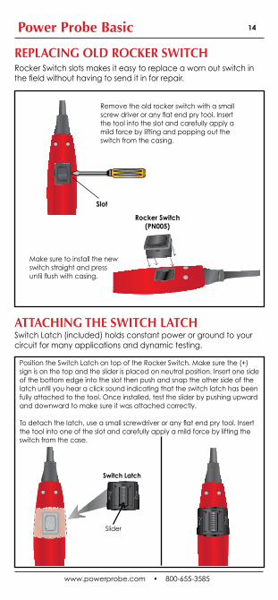
Rocker Switch slots makes it easy to replace a worn out switch in the field without having to send it in for repair.
Switch Latch (included) holds constant power or ground to your circuit for many applications and dynamic testing.
Remove the old rocker switch with a small screw driver or any flat end pry tool. Insert the tool into the slot and carefully apply a mild force by lifting and popping out the switch from the casing.
Make sure to install the new switch straight and press until flush with casing.
Rocker Switch(PN005)
Slot
Position the Switch Latch on top of the Rocker Switch. Make sure the (+) sign is on the top and the slider is placed on neutral position. Insert one side of the bottom edge into the slot then push and snap the other side of the latch until you hear a click sound indicating that the switch latch has been fully attached to the tool. Once installed, test the slider by pushing upward and downward to make sure it was attached correctly.
To detach the latch, use a small screwdriver or any flat end pry tool. Insert the tool into one of the slot and carefully apply a mild force by lifting the switch from the case.
Switch Latch
Slider

www.powerprobe.com • 800-655-3585
Power Probe Basic 15
In most cases a short circuit will appear by a fuse or a fusible link blow-
ing or a protection device tripping (i.e., a circuit breaker). Here is the
best place to begin the search.
Remove the blown fuse from the fuse box.
Use the Power Probe tip to energize each of both contacts in the fuse
box. The side which trips the Power Probe circuit breaker is the shorted
circuit. Take note of this wire identification code or color. Follow the wire
as far as you can along the wiring harness, for instance if you are fol-
lowing a short in the brake light circuit you may know that the wire must
pass though the wiring harness at the door sill. Locate the color-coded
wire in the harness and expose it. Probe through the insulation of the
wire with the Power Probe tip and depress the power switch forward to
energize the wire. If the Power Probe circuit breaker tripped you have
verified the shorted wire. Cut the wire and energize each end with the
Power Probe tip. The wire which trips the Power Probe circuit breaker
again will lead you to the shorted area. Follow the wire in the shorted
direction and repeat this process until the short is located.
FOLLOWING AND LOCATING SHORT CIRCUITS
Power Probe products undergo a strict quality control inspection for workmanship, function, and safety before leaving the factory. From the date of purchase, we will warranty/repair Power Probe products for one (1) year against defects in parts and workmanship. All repairs due to misuse will be charged a fee not to exceed the cost of the tool. All warranty units must be accompanied by a copy of the original sale receipt. In the event of a malfunction or defective unit, please call or write your Power Probe dealer.
Power Probe Warranty

www.powerprobe.com • 800-655-3585
Power Probe Basic 16
ESPAÑOL
TABLA DE CONTENIDO
INTRODUCCIÓN .......................................................................17
ADVERTENCIA ......................................................................... 17
LA SEGURIDAD ......................................................................... 18
CARACTERÍSTICAS ...................................................................19
ENGÁNCHE .............................................................................. 20
PRUEBA RÁPIDA .......................................................................20
PRUEBA DE POLARIDAD ......................................................... 21
PRUEBAS DE CONTINUIDAD .................................................... 22
ACTIVACIÓN COMPONENTES REMOVIDOS ........................ 23
PRUEBA DE LUCES Y CONEXIONES DE REMOLQUE ............. 24
PRUEBA DE ALIMENTACIÓN DE TIERRA .................................. 25
ACTIVACIÓN DE LOS COMPONENTES ELÉCTRICOS
CON VOLTAJE POSTIVO (+) .................................................26
CAMBIO DE TIERRA DE UN CIRCUITO QUE
CONTIENE CARGA ELÉCTRICA ........................................... 27
REMPLAZO DE ROCKER SWITCH ............................................ 28
INSTALANDO EL SWITCH LATCH ............................................. 28
SIGUIENDO Y LOCALISANDO LOS CORTO CIRCUITOS ....... 29
LA GARANTIA DE POWER PROBE ........................................... 29
www.powerprobe.com • 800-655-3585
Power Probe Basic 17
INTRODUCCIÓN
Gracias por adquirir el Power Probe BASIC. Es el mejor valor para el ensayo de los problemas eléctricos del automóvil.
Después de conectarlo a la batería del vehículo se puede ver si un circuito es positivo, negativo o abierto sondeándolo y observando el LED ROJO o VERDE. Puede activar rápidamente los componentes eléctricos con solo presionar el switch de alimentación y sí, el cortocircuito es protegido. La continuidad de los interruptores, relés, diodos, fusibles y cables se prueban fácilmente mediante la conexión entre el cable de masa auxiliar y la punta de la sonda y observando el LED VERDE. Compruebe los fusibles y prueba de cortocircuitos. Encuentra las conexiones de tierra defectuosas al instante. El cable de 20 pies. de largo alcanzará de defensa a defensa y tiene la opción de conectar un cable de extensión de 20 pies para hacerla llegar hasta 40 pies. Genial para camiones, remolques y autocaravanas. Si no estás utilizando un Power Probe en su prueba eléctrica, estás perdiendo el tiempo.
Antes de utilizar el Power Probe BASIC, por favor, lea las instrucciones cuidadosamente.
¡ADVERTENCIA!
Cuando se oprime el interruptor de alimentación, la corriente se lleva a cabo directamente hacia la punta que puede causar chispas al contacto con el suelo o ciertos circuitos. Por tanto, Power Probe NO se debe utilizar en torno inflamables como gasolina o sus vapores. La chispa de un Power Probe con energía podría encender estos vapores. Usa la misma precaución que lo harías al usar un soldador de arco.
Power Probe Basic no está diseñado para ser utilizado con corriente doméstica AC 110/220 voltios, ya que es sólo para uso con sistemas de 6-12 VDC.

www.powerprobe.com • 800-655-3585
Power Probe Basic 18
LA SEGURIDAD
Precaución - Leer Por PavorPara evitar posibles descargas eléctricas, lesiones personales o evitar daños en la unidad, por favor utilice Power Probe Basic de acuerdo con los siguientes procedimientos de seguridad. Power Probe recomienda leer este manual antes de usar Power Probe Basic.
El Power Probe Basic está estrictamente diseñado para sistemas eléctricos del vehículo. Es utilizado en 6-12 voltios DC solamente. El interruptor de alimentación no debe ser presionado cuando se conecta a los módulos de control electrónico, sensores o cualquiera de los componentes electrónicos sensibles. NO conectes el Power Probe al AC eléctrico tal como 115 voltios.
No conecte el sistema eléctrico con alto voltaje nominal que se indica en este manual.
No se debe pasar tensión superior a la tensión nominal del Power Probe Basic.
Revisa el Power Probe BASIC en busca de grietas o daños. Daños en caso de fugas de alto voltaje puede causar un riesgo de electro-cución.
Revisa el Power Probe BASIC por cualquier daño en el aislamiento o cables pelados. Si está dañado, no utilice la herramienta,por favor contacta el soporte técnico de Power Probe.
Use conductores y los accesorios envueltos autorizados por Power Probe para reducir al mínimo las conexiones eléctricas conductoras expuestas para eliminar el riesgo de descargas.
No intente abrir el Power Probe BASIC, no hay piezas que puedan ser reparadas. La apertura de esta unidad anulará la garantía. Todas las reparaciones deben ser realizadas en centros de servicio autorizados por Power Probe.
Durante el mantenimiento del Power Probe, utilice sólo piezas de repuesto certificadas por el fabricante.
Usar sólo en áreas bien ventiladas. No opere cerca de materiales inflamables, vapor o polvo.
Tenga cuidado al energizar los componentes que sean partes móviles, que contienen conjuntos de motores o solenoides de alta potencia.
Power Probe, Inc. no será responsable de los daños a los vehículos o componentes por la causa del mal uso, manipulación o accidente.
Power Probe, Inc. no será responsable por cualquier daño causado por accidentes, mal uso intencional de nuestros productos o herramientas.
Si usted tiene alguna pregunta, por favor visite nuestro sitio web en: www.powerprobe.com o póngase en contacto con nuestro soporte técnico en: 800-655-3585.
www.powerprobe.com • 800-655-3585
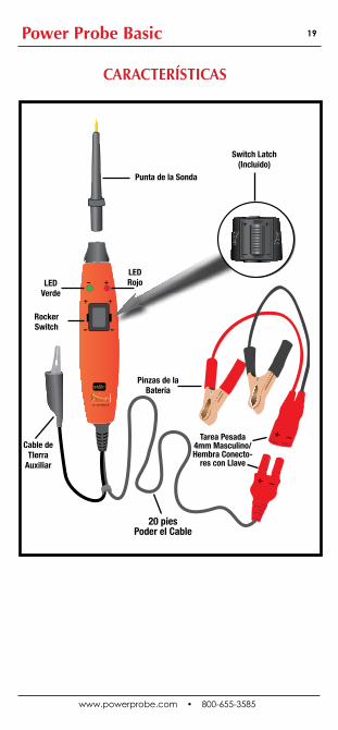
Power Probe Basic 19
6 -12 VOLTS
Punta de la Sonda
LEDVerde
LEDRojo
Rocker Switch
Pinzas de la Batería
Tarea Pesada4mm Masculino/Hembra Conecto-
res con Llave
20 piesPoder el Cable
CARACTERÍSTICAS
Switch Latch(Incluido)
Cable de TIerra
Auxiliar

www.powerprobe.com • 800-655-3585
Power Probe Basic 20
6 -12 VOLTS
BATTERY
ENGÁNCHE
PRUEBA RÁPIDA
Desenrolla el cable de alimentación.Sujeta el clip rojo de la batería al terminal POSITIVO de la batería del vehículo.Sujeta el clip negro de la batería al terminal NEGATIVO de la batería del vehículo.
Precione el interruptor de alimentación hacia delante (+), el indica-dor LED se iluminará en ROJO.Precione el interruptor de encendido hacia atrás (-), el indicador LED se iluminará en VERDE.El Power Probe Basic está ahora listo para su uso..
LEDRojo
LED Verde
Posición Delantero
Posición Hacia Atrás

www.powerprobe.com • 800-655-3585
Power Probe Basic 21
BATTERY
6 -12 VOLTS
6 -12 VOLTS
BATTERY
PRUEBA DE POLARIDADContacta la punta del Power Probe al POSITIVO (-) del circuito se iluminará el indicador LED ROJO.Contacta la punta del Power Probe al NEGATIVO (-) del circuito se iluminará el indicador LED VERDE.Contacta la punta del Power Probe a un proceso abierto, el circuito será indicado por el indicador LED no iluminación.
LED Rojo = Positivo
LED Verde = Negativo

www.powerprobe.com • 800-655-3585
Power Probe Basic 22
PRUEBAS DE CONTINUIDAD
Aplicación de Continuidad
Mediante el uso de la punta junto con el cable de tierra auxiliar, se puede probar la continuidad en los cables y componentes que están desconectados del sistema eléctrico del vehículo.
Cuando la continuidad está presente, el indicador LED se ilumina en verde.
6 -12 VOLTS
BATTERY BATTERY
6 -12 VOLTS
No LED = No Continuidad LED Verde = Continuidad

www.powerprobe.com • 800-655-3585
Power Probe Basic 23
ACTIVACIÓN DE COMPONENTES REMOVIDOSMediante el uso de la punta del Power Probe junto con el cable de tierra auxiliar, los componentes pueden ser activados, probando así su función.
Conecta la terminal positiva del componente, el indicador LED se iluminará indicando la continuidad en el componente a través de la luz VERDE.
Mientras que observa el indicador LED verde, rápidamente presione y suelte el interruptor de alimentación hacia delante (+). Si el indicador verde cambió instantáneamente de verde a rojo, puede proceder con la activación adicional. Si el indicador verde se apaga en ese instante o si el interruptor automático se disparó, el Power Probe Basic se ha sobrecargado. Esto podría ocurrir por las siguientes razones:• El contacto es una tierra directa o voltaje negativo.• El componente está en cortocircuito.• El componente es de alto amperaje (es decir, el motor de arranque). Si el interruptor automático se dispara, se restablecerá automática-mente a la posición original.
6 -12 VOLTS
BATTERY
Conecta la pinza auxiliar negativa a la base de la
bombillaConecta la punta a la terminal positiva de la
bombilla
Pulsa el rocker switch hacia adelante para activar la bombilla
Aparte de focos, también puede activar otros com-ponentes como bombas de combustible, motores de ventanas, solenoides de arranque, ventiladores de refrigeración, motores, etc.

www.powerprobe.com • 800-655-3585
Power Probe Basic 24
BATTERY
6 -12 VOLTS
PRUEBA DE LUCES Y CONEXIONES DE REMOLQUE1. Conecta el Power Probe Basic a una buena batería.
2. Engancha el clip de tierra auxiliar a la tierra del remolque.
3. Prueba los contactos del conector y aplique voltaje a ellos.Esto le permite comprobar la función y ubicación de las luces del remolque. Si el interruptor automático se dispara, se va a reiniciar automáticamente después que se enfríe.
• Identifica qué terminales enciende las luces específicamente
• Encuentra cables en cortocircuitos
• Muestra cables abiertos o rotos
8 Amps = No se activa el interruptor automático10 Amps = 20 segundos15 Amps = 6 segundos25 Amps = 2 segundosCortocircuito = 0.3 segundos
ESPECIFICACIONES DE RESPUESTAS CUANDO SE DISPARA EL CIRCUIT BREAKER

www.powerprobe.com • 800-655-3585
Power Probe Basic 25
BATTERY
6 -12 VOLTS
BATTERY
6 -12 VOLTS
El LED Rojo No Se Ilumina
La Luz Roja LED Se Enciende
La resistencia a Tierra
El circuit breaker se
dispara
No se dispara el circuit breaker
En primer lugar asegúrese de que la alimentación de tierra que se está probando es realmente un alimento de tierra. No se deben activar los circuitos de control electrónicos o controladores con 12 voltios al menos que estén diseñados para 12 voltios.
Es fácil de probar una potencia de tierra de alimentación, utilizando cables de calibre de 20 a 18. Puede determinar si la alimentación de tierra es buena o defectuosa con simplemente el toque de la punta de la prueba y aplicando alimentación presionando el interruptor del encendido.
Si el interruptor de circuito se dispara y NO HAY LUZ ROJA, la ali-mentación de tierra se puede considerar una buena tierra. Si el LED rojo se enciende, la alimentación de tierra es defectuosa. Es así de simple.
PRUEBA DE ALIMENTACIÓN DE TIERRA
DISPARE DEL INTERRUPTOR AUTOMÁTICO (CIRCUITBREAKER) = BUENA CONEXIÓN A TIERRA
LA LUZ LED ROJA ESTÁ ENCENDIDA = MALA CONEXIÓN A TIERRA
Fusible
Fusible

www.powerprobe.com • 800-655-3585
Power Probe Basic 26
ACTIVACIÓN DE LOS COMPONENTES ELÉCTRICOS CON VOLTAJE POSITIVO (+)Para activar los componentes con voltaje positivo (+): Contacta la punta de la prueba al terminal positivo del componen-te. El indicador LED se iluminará en verde.Mientras que observas el indicador verde, rápidamente presiona y suelta el interruptor de alimentación hacia delante (+). Si el indicador verde cambió instantáneamente de verde a rojo, puedes proceder con la activación adicional.Si el indicador verde se apaga en ese instante o si el interruptor au-tomático se dispara, el Power Probe se ha sobrecargado. Esto podría ocurrir por las siguientes razones:• El contacto es una tierra directa.• El componente está en cortocircuito.• El componente es de alto corriente (es decir, el motor de arran-que). Si el interruptor automático se activa, se va a restablecer automáticamente..
Advertencia: El uso indebido y la aplicación de tensión a ciertos circuitos pueden causar daños a los componentes electrónicos de un vehículo. Por lo tanto, se recomienda encarecidamente utilizar el procedimiento de esquema y el diagnóstico correcto durante las pruebas.
BATTERY
6 -12 VOLTS
Fusible
Motor

www.powerprobe.com • 800-655-3585
Power Probe Basic 27
CAMBIO DE UN CIRCUITO DE TIERRA CON UNA CARGA ELÉCTRICA
Haz contacto con la punta de la prueba al circuito que desea volver a encender aplicando tierra. El LED rojo debe encenderse, indicando que el circuito tiene una alimentación positiva a través de la carga.
Mientras que observas el LED rojo, presiona y suelta rápidamente el interruptor de encendido hacia atrás (-). Si el LED verde se encendió, se puede proceder con la activación adicional.
Si el LED verde no encendió durante la prueba, o si el interruptor au-tomático se dispara, El Power Probe Basic ha sido sobrecargado. Esto podría ocurrir por las siguientes razones:• La punta está conectada directamente a un circuito positivo.• El componente está internamente en cortocircuito • El componente es de alto corriente (es decir, el motor de arranque).• Si el interruptor automático se dispara, se va a restablecer automáti-camente después que se enfríe durante un breve período. (Típica-mente de 2 a 4 segundos)
BATTERY
6 -12 VOLTS
Fusible
Motor
Pulsa el rocker switch hacia atrás para
conectar tierra al motor

www.powerprobe.com • 800-655-3585
Power Probe Basic 28
REMPLAZO DEL ROCKER SWITCH
INSTALANDO EL SWITCH LATCH
Las ranuras del rocker switch hacen que sea más fácil re-emplazar el interruptor en ese instante, sin tener que enviarlo a reparación.
El switch latch mantiene una potencia constante de poder y de tierra a su circuito para muchas aplicaciones y pruebas dinámicas.
Remueve el interruptor con un pequeño destornillador o herramienta de palanca plano extremo. Inserte la her-ramienta en el espacio y aplique cuidadosamente una ligera fuerza levantando y despegándolo de la unidad.
Asegúrese de instalar el nuevo interruptor recto y presione hasta que quede nivelado con la cubierta.
Rocker Switch(PN005)
Espacio
Coloque el switch latch arriba del rocker switch. Asegúrese de que el signo (+) está en la parte superior y el deslizador se coloca en posición neutral. Inserta a un lado del canal inferior y luego empuja y encaja el otro lado del seguro hasta que escuche un sonido de clic que indica que el seguro del interruptor ha sido totalmente unido a la unidad. Una vez instalado, se prueba presionando el control deslizándolo hacia arriba y hacia abajo para asegurarse de que se ha instalado correctamente.
Para separar el seguro, utilice un pequeño destornillador o cualquier herramienta de palanca extremo plano. Inserte la herramienta en una de las ranuras y aplique cuidadosamente una fuerza leve levantando el interruptor de la unidad.
Switch Latch
Deslizador
www.powerprobe.com • 800-655-3585
Power Probe Basic 29
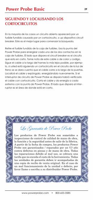
En la mayoría de los casos un circuito abierto aparecerá por un
fusible fundido causado por un cortocircuito, o up dispositivo circuit
breaker. Este es el mejor lugar para comenzar la búsqueda.
Retire el fusible fundido de la caja de fusibles. Usa la punta del
Power Probe para energizar cada uno de los dos contactos en la
caja de fusibles. El lado que dispara el circuit breaker es el circuito
que esta en corto. Tome nota de este cable o de color y codigo.
Sigue el cable a lo largo del harnes lo más lejos posible, por ejemp-
lo, si usted está siguiendo un cortocircuito en el circuito de la luz de
freno se se dara cuenta que el cable corre a lo largo de la puertas.
Localicé el cable y expóngalo, energizándolo nuevamente. Si el
interruptor de circuito de Power Probe se dispara habrá verificado
el cable con cortocircuito. Corta el cable y da energía a cada
extremo con la punta de Power Probe. El lado que dispara el inter-
ruptor es el área de donde está en corto.
SIGUIENDO Y LOCALISANDO LOS CORTOCIRCUITOS
Los productos de Power Probe son sometidos a inspecciones de control de calidad de mano de obra, la función y la seguridad antes de salir de la fábrica. A partir de la fecha de compra, los productos Power Probe son garantizados / reparados por un (1) año contra defectos en piezas y de mano de obra. Todas las reparaciones debido al mal uso, se cobrara una tarifa que no exceda el costo de la herramienta. Todas las unidades de garantía deben ir acompañadas de una copia de recibo de venta original. En el caso de un mal funcionamiento de la unidad o defecto, por favor llame o escriba a su distribuidor Power Probe.
La Garantía de Power Probe

www.powerprobe.com • 800-655-3585
Power Probe Basic 30
760 Challenger St. • Brea, CA 92821
800-655-3585 • Fax (714) 990-9478
www.powerprobe.com
300-00012