
Instruction manual September 2016 INM 9466 rev 3 MTL9466-ET
20
MTL9466-ET Managed Ethernet Switch September 2016 INM 9466 rev 3 Instruction manual MTL intrinsic safety solutions
Transcript of Instruction manual September 2016 INM 9466 rev 3 MTL9466-ET

MTL9466-ET Managed Ethernet Switch
September 2016INM 9466 rev 3
Instruction manualMTL intrinsic safety solutions

ii INM9466 rev 3
DECLARATION OF CONFORMITY
A printed version of the Declaration of Conformity has been provided separately within the original shipment of goods. However, you can find a copy of the latest version at http://www.mtl-inst.com/certificates

iiiINM9466 rev 3
CONTENTS
DECLARATION OF CONFORMITY . . . . . . . . . . . . . . . . . . . . . . . . . . . . . . . . . . . . . . . . . . . II
1 . FEATURES . . . . . . . . . . . . . . . . . . . . . . . . . . . . . . . . . . . . . . . . . . . . . . . . . . . . . . . . . . . . 1
2 . DESCRIPTION . . . . . . . . . . . . . . . . . . . . . . . . . . . . . . . . . . . . . . . . . . . . . . . . . . . . . . . . . 2
3 . INSTALLATION . . . . . . . . . . . . . . . . . . . . . . . . . . . . . . . . . . . . . . . . . . . . . . . . . . . . . . . . 2
3 .1 Protection . . . . . . . . . . . . . . . . . . . . . . . . . . . . . . . . . . . . . . . . . . . . . . . . . . . . . . . . . . . . . . . .2
3 .2 Mechanical mounting . . . . . . . . . . . . . . . . . . . . . . . . . . . . . . . . . . . . . . . . . . . . . . . . . . . . . . .3
3 .3 . Electrical connections . . . . . . . . . . . . . . . . . . . . . . . . . . . . . . . . . . . . . . . . . . . . . . . . . . . . . . .3
4 PC PACKAGE REQUIREMENTS . . . . . . . . . . . . . . . . . . . . . . . . . . . . . . . . . . . . . . . . . . . . . 4
5 SOFTWARE INSTALLATION . . . . . . . . . . . . . . . . . . . . . . . . . . . . . . . . . . . . . . . . . . . . . . . 4
6 COMMUNICATING WITH THE 9466-ET . . . . . . . . . . . . . . . . . . . . . . . . . . . . . . . . . . . . . . 4
6 .1 In the safe area . . . . . . . . . . . . . . . . . . . . . . . . . . . . . . . . . . . . . . . . . . . . . . . . . . . . . . . . . . .4
6 .2 In the hazardous area . . . . . . . . . . . . . . . . . . . . . . . . . . . . . . . . . . . . . . . . . . . . . . . . . . . . . .4
7 LAUNCHING THE PROGRAM . . . . . . . . . . . . . . . . . . . . . . . . . . . . . . . . . . . . . . . . . . . . . . 4
8 MAIN SCREEN . . . . . . . . . . . . . . . . . . . . . . . . . . . . . . . . . . . . . . . . . . . . . . . . . . . . . . . . 5
8 .1 Menu Bar . . . . . . . . . . . . . . . . . . . . . . . . . . . . . . . . . . . . . . . . . . . . . . . . . . . . . . . . . . . . . . . .5
9 VLAN . . . . . . . . . . . . . . . . . . . . . . . . . . . . . . . . . . . . . . . . . . . . . . . . . . . . . . . . . . . . . . . 6
10 RATE LIMIT . . . . . . . . . . . . . . . . . . . . . . . . . . . . . . . . . . . . . . . . . . . . . . . . . . . . . . . . . . . 7
11 MIRRORING . . . . . . . . . . . . . . . . . . . . . . . . . . . . . . . . . . . . . . . . . . . . . . . . . . . . . . . . . . 8
12 MIB COUNTERS . . . . . . . . . . . . . . . . . . . . . . . . . . . . . . . . . . . . . . . . . . . . . . . . . . . . . . . 9
13 STATIC MAC ADDRESSES . . . . . . . . . . . . . . . . . . . . . . . . . . . . . . . . . . . . . . . . . . . . . . . . . 9
14 DYNAMIC MAC ADDRESSES . . . . . . . . . . . . . . . . . . . . . . . . . . . . . . . . . . . . . . . . . . . . . 10
15 DOWNLOADING NEW SOFTWARE . . . . . . . . . . . . . . . . . . . . . . . . . . . . . . . . . . . . . . . . 10
16 ENVIRONMENTAL . . . . . . . . . . . . . . . . . . . . . . . . . . . . . . . . . . . . . . . . . . . . . . . . . . . . . 11
17 WASTE REMOVAL INFORMATION . . . . . . . . . . . . . . . . . . . . . . . . . . . . . . . . . . . . . . . . . 11
18 ACCESSORIES . . . . . . . . . . . . . . . . . . . . . . . . . . . . . . . . . . . . . . . . . . . . . . . . . . . . . . . . 11
19 APPROVALS . . . . . . . . . . . . . . . . . . . . . . . . . . . . . . . . . . . . . . . . . . . . . . . . . . . . . . . . . 12
20 FM CERTIFICATION INFORMATION . . . . . . . . . . . . . . . . . . . . . . . . . . . . . . . . . . . . . . . . 12
21 ATEX & IECEx CERTIFICATION INFORMATION . . . . . . . . . . . . . . . . . . . . . . . . . . . . . . . . 12

iv INM9466 rev 3
THIS PAGE IS LEFT INTENTIONALLY BLANK

1INM9466 rev 3
1 . FEATURES ♦ Intrinsically Safe ATEX / IECEx certified / FM / FMC approved
♦ Ga Ex ia IIC T4 GD (surface), Ma Ex ia I M1 (mining)
♦ Zone 1/ Division 1 mounting in a suitable enclosure
♦ Input voltage: 12V dc nominal (10 – 15.4V)
♦ Input current 200mA
♦ Extended temperature range (–20°C…+70°C)
♦ PoEx™ - “Power over Ethernet” power sourcing equipment - distributes device supplies via the RJ45 ports*
♦ 5x Port 10/100Mb Ethernet twisted pair (Cat5e) RJ45 Connections (100m max)
♦ Status LED’s For :
‘Power On’Copper UTP ‘Half/Full Duplex’ (each port)Copper UTP ‘10Mbps/Activity’ (each port)Copper UTP ‘100Mbps/Activity’ (each port)
♦ 10/100Mbps Half/Full Duplex with Auto-Negotiation
♦ Supports MDI / MDI-X auto crossover (easy cascading of switches with standard straight connected 1:1 cables)
♦ Broadcast storm protection – eliminates network overload caused by excessive ‘broadcast’ and ‘multicast’ packets.
♦ Intelligent Routing - Automatic address learning, aging and migration
♦ Supports IEEE 802.3: 10Base-T, 100Base-TX
♦ IEEE 802.1q Tag/Port based VLAN, Quality of Service (QoS) priority
♦ Programmable Managed features (Serial port) VLAN, Rate Limiting, Port Mirroring etc
♦ DIN-rail mounting module
*Note – PoEx is a simple adaptation of the IEEE 802.3af Power over Ethernet (PoE) standard to bring the benefits to the 9400 Range of Hazardous Area devices. This allows two spare pairs in the existing Cat5e cable to distribute the power supply from a 9466-ETEthernet Switch (Power Sourcing Equipment – PSE) to each of the devices connected to its five ports (PD – Powered Device). This adaptation is necessary due to restrictions for Hazardous Area use. It is not implied that the device conforms to the 802.3af (PoE) standard.
9466-ET - Managed Ethernet Switch

2 INM9466 rev 3
2 . DESCRIPTIONThe 9466-ET 10/100Mbps Managed Layer 2 Ethernet Switch allows the interconnection of other 9460-ET Series networking modules via its 5x ports, it also enables an Ethernet network to cover a greater distance, either using Cat5e cable or fibre-optic for longer spans, this is down to the low latency ‘store and forward’ mechanism integral to the switch which ensures that the stringent timing associated with Ethernet is maintained. With the 9466-ET switch, each connection is effectively a ‘point-to-point’ network segment unlike the older generation hubs that were simple ‘dumb’ repeaters – these needed to impose a limit on overall network length to ensure proper collision detection, this limit is overcome by using the 9466-ET.
The 9466-ET switch can also distribute power to compatible devices connected to each of its five ports via the RJ45 Cat5e cables (PoEx), this eliminates the separate power supply cable to the device simplifying installation and maintenance.
The default mode of operation is a 5 port unmanaged switch with auto negotiation. However the onboard EEPROM memory can be configured via the serial RS232/TTL port either in the Safe Area, using a PC; or in the Hazardous Area using the 9461-ET Ethernet Gateway as its host processor. Features such as Programmable Rate Limiting, VLAN support Port Mirroring and Forced Speed and Duplex settings may be configured in this way if required. The 9461-ET module can also perform its usual function of a serial communications gateway (eg: serial Modbus to Ethernet conversion) whilst giving ‘online’ access to the managed features of the 9466-ET switch over the Ethernet network, including the MIB counters for each port.
3 . INSTALLATIONWARNING: This equipment must be installed, operated and maintained only be trained competent personnel and in accordance with all appropriate international, national and local standard codes of practice and site regulation for intrinsically safe apparatus and in accordance with the instructions contained here. See also Sections 19, 20 & 21 for approvals and important conditions of safe use.
3 .1 ProtectionThe module requires mounting within an enclosure providing a degree of protection of at least IP6x, in accordance with EN60529 and in a manner that does not impair the existing creepage and clearance distances. The enclosure must also comply with the requirements of Clauses 7 and 8 of EN50014 and be sealed to prevent the ingress of dust.
��
�� ��
���
������
�������

3INM9466 rev 3
3 .2 Mechanical mounting
3 .2 .1 DIN rail mounting
The module will ‘snap-fit’ onto standard DIN rail (TS35) to EN 50022. Height off rail - including any connectors but excluding cables = 106mm. Tilt the module to engage the top DIN rail clips then rotate down and press to the DIN rail until the lower spring clip is properly engaged.
3 .2 .2 Flat panel mounting
The module has two fixing holes to enable it to be mounted with two M3.5 screws. Use the dimension diagram on the previous page to establish the hole positions. Depth - including connectors but excluding cables = 111mm.
3 .3 . Electrical connections
3 .3 .1 Screw Terminals
DC power input
Terminal No . Function1 +12V dc in
9466-ETmodule supply2 +12V dc in3 0V4 0V5 No connection6 +12V dc in
PoEx - Port 1 (see Note 2)7 0V8 +12V dc in
PoEx - Port 2 (see Note 2)9 0V10 +12V dc in
PoEx - Port 3 (see Note 2)11 0V12 +12V dc in
PoEx - Port 4 (see Note 2)13 0V14 +12V dc in
PoEx - Port 5 (see Note 2)15 0V
Note: 1. Terminals 1 & 2 and 3 & 4 are linked internally. 2: For PoEx – connect IS supplies to terminals 6 to 15 as required.
WARNING: The supply for PoEx must be derived from a suitably certified, intrinsically safe supply.
3 .3 .2 Front Panel Connectors
10/100 BASE-T Ethernet RJ45
Pin No . Function
1 TX +
2 TX –3 RX +4 Supply 12V - PoEx5 Supply 12V - PoEx
6 RX –
7 Supply 0V - PoEx8 Supply 0V - PoEx
As the 9466-ET Ethernet switch supports Auto MDI/MDI-X, a straight connected RJ45 Cat5e cable is used to connect to any device.
It is recommended that Cat5e cables for Hazardous Area Zone 1 use are ‘Blue’ in colour and are of good quality (see accessories section), the Safe Area cables being a colour other than blue to aid identification.
� � � � � � � � �� �� �� �� �� ��

4 INM9466 rev 3
4 PC PACKAGE REQUIREMENTSIn order to run the package on a PC, the following minimum system configuration is required:-
• Pentium® 3 Processor or Equivalent
• 256 Mb RAM minimum
• Windows® 98(or higher)
• Serial Communications Port
5 SOFTWARE INSTALLATIONNote: Sections 5 through to 15 are relevant only if you require the 9466-ET switch to operate in the managed mode .
The 9466-ET Ethernet switch management software is provided on a CD along with the hardware. If the CD is not available for some reason, download the software from the Industrial Networks section of our website at www.mtl-inst.com.
If installing from the CD - Place the CD into the CD or DVD drive on a PC. If the Setup application does not Autorun then use Start|Run from the Windows menu and run the setup.exe application on the CD to launch the installation program.
If installing from downloaded files - Unzip the file into a temporary directory, then run the resulting setup.exe application in that directory to launch the installation program.
In either case, this is a conventional installation program that requires the user to specify a destination directory for the application software, after which the setup will continue. Follow the on-screen instructions to complete the installation.
6 COMMUNICATING WITH THE 9466-ET
6 .1 In the safe areaConnect the 9466-ET Ethernet Switch to your PC using the CAB9466 RS communications lead that is supplied with the switch. The 9-pin minature D-type connector should be plugged into a Serial Communications (COM) port on the PC and the other end of the cable should be plugged into the RS232 connector on the front panel of the 9466-ET Switch. Apply 12V dc power to the switch and then open the Configuration Software application.
6 .2 In the hazardous areaIf the 9466-ET is installed in an intrinsically safe system in the hazardous area then the 9461-ET Etthernet Gateway is required to connect to the 9466-ET from the safe area. Set up the 9461-ET as instructed in its manual
7 LAUNCHING THE PROGRAMTo run the program, double click the 9466-ET Management icon. A splash screen, of the type shown below, will appear which displays the version number of the software.

5INM9466 rev 3
8 MAIN SCREENThe following screen is the main page of the software and appears upon launch. On the left it shows the status of the switch along with version numbers.
To the right of the status is the port usage. This provides an easy to view insight into the amount of throughput on the switch and whether the Ethernet Architecture needs any maintenance.
Below these vertical bars are the settings for each of the ports, the link Speed/Duplex Mode, Broadcast Storm Protection, Back Pressure, Learning and Port ON/Off.
At the side there are the options regarding Aging. This allows for aging to be enabled, with Link Change or Fast and whether Aggressive Back Off is required.
In order to alter any of the parameters, Value Editing must be enabled. This is done by clicking on the Enable Value Editing Menu Bar option and entering the password: 216231
Note: Value editing permission times-out after approximately 5 minutes.
After modifications are made they need to be sent or saved to the switch. Sending to the switch is only temporary and will be lost on a power down whereas saving is permanent.
Also on this, and every, page is the status bar at the bottom. This records the last event that has happened. Events can include Switch Offline, Settings Saved or Sent etc.
8 .1 Menu BarAt the top of the window is the menu bar, which gives the following options:-
File MenuOpen and Send Settings to the SwitchThis option allows the user to open a switch settings file and send it to the switch. These settings will not be stored and will be lost after a power down.
Open and Save settings to the SwitchThis option allows the user to open a switch settings file and save it to the switch.
Save Switch SettingsThis option allows the user to save the current switch settings to a file.
Comm Port SettingUse this to specify the PC comm port that is connected to the switch. Enter a valid number and click OK.
ExitThis option allows the user to exit the Switch Management Software.
6 INM9466 rev 3
Update Switch Software
This password controlled option allows you to change the software running in the 9466-ET. This function is only recommended in a controlled environment.
Enable Value Editing
This option asks for a password which will enable value editing. This step is essential for modifying the details contained on the tabbed pages described in the next sections.
Help
This opens up a PDF version of this document.
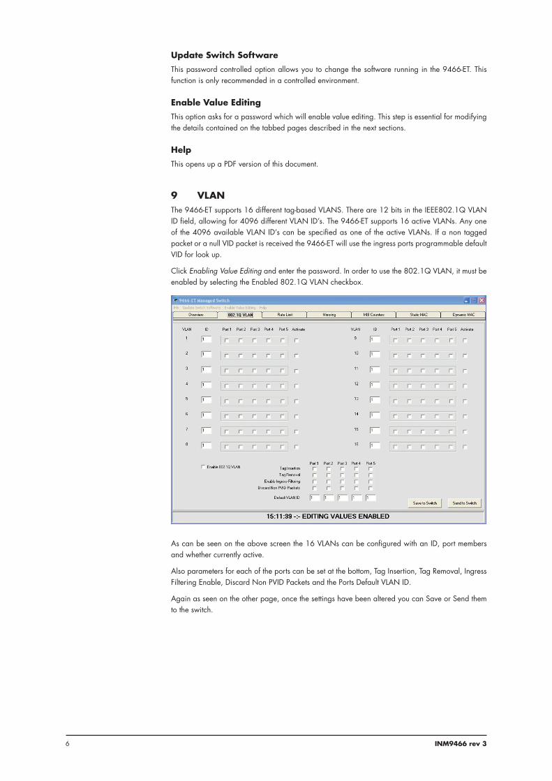
9 VLANThe 9466-ET supports 16 different tag-based VLANS. There are 12 bits in the IEEE802.1Q VLAN ID field, allowing for 4096 different VLAN ID’s. The 9466-ET supports 16 active VLANs. Any one of the 4096 available VLAN ID’s can be specified as one of the active VLANs. If a non tagged packet or a null VID packet is received the 9466-ET will use the ingress ports programmable default VID for look up.
Click Enabling Value Editing and enter the password. In order to use the 802.1Q VLAN, it must be enabled by selecting the Enabled 802.1Q VLAN checkbox.
As can be seen on the above screen the 16 VLANs can be configured with an ID, port members and whether currently active.
Also parameters for each of the ports can be set at the bottom, Tag Insertion, Tag Removal, Ingress Filtering Enable, Discard Non PVID Packets and the Ports Default VLAN ID.
Again as seen on the other page, once the settings have been altered you can Save or Send them to the switch.

7INM9466 rev 3
10 RATE LIMITThe 9466-ET supports programmable rate limiting on a per port basis. After password entry, Transmit and receive rate limits for each port can also be programmed independent of one another. The user can program a different rate limit for high and low priority packets. The rate limit can be programmed up to the line rate in increments of 32,768 bps.
On the above screen the rates can be set in Mbps for both low and high priority messages. To limit High priority messages ensure the Disable Priority check boxes are not selected. The rate limits can be enabled by selecting the check boxes on the appropriate limit. The priority for each port can be set to be Diffser, 802.1P, Port Based or None.
Again as seen on the previous pages, once the settings have been altered you can Save or Send them to the switch.

8 INM9466 rev 3
11 MIRRORINGThe 9466-ET provides a facility to mirror (i.e.copy) information on one, or more, ports to other ports. Three options are available after Enabling Value Editing using the password.
• “Receive only” port mirroring
Information received on a port can be mirrored (copied) to another port(s).
• “Transmit only” port mirroring
Information transmitted on a port can be mirrored to another port (s).
• “Receive and Transmit” port mirroring
Information received on a port and information transmitted on a port can be mirrored to another port(s).
Specify the port(s) by checking the boxes for the ports. In the first column (Mirror Port) you specify the ports to receive the mirrored information, then check boxes in the second and third columns to specify which ports are to mirror their Tx or Rx data respectively.

9INM9466 rev 3
12 MIB COUNTERSThe 9466-ET offers 34 MIB counters per port. These counters are used to monitor port activity for network management. Click Enabling Value Editing and enter the password.
Use the button at the bottom of the display to zero the MIB counters and remove earlier stats.
13 STATIC MAC ADDRESSESThe 9466-ET offers 8 static MAC settings. These can be allocated a VLAN ID or set at 0 to allow MAC lookup. Click Enabling Value Editing and enter the password.
The port to forward the messages for the static MAC can be selected and whether or not to override the spanning tree. Static MACs can be activated or deactivated using the checkbox on the far right.
These settings can easily be Saved or Sent to the switch by clicking one of the buttons in the lower right corner of the display.

10 INM9466 rev 3
14 DYNAMIC MAC ADDRESSESThe Dynamic MAC address page shows all the devices visible on each of the 5 ports of the 9466-ET switch. Click Enabling Value Editing and enter the password.
Click the Refresh List button to refresh the list if required.
15 DOWNLOADING NEW SOFTWARE
The 9466-ET has the facility to upgrade its software. To begin this action, select the Update Switch
Software menu bar option, which will bring up the password dialog box.
After password entry a file selection window will appear.
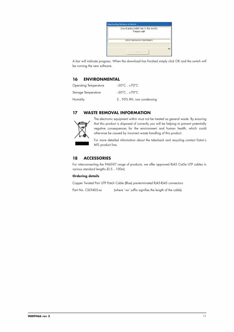
Select the software file you wish to load into the 9466-ET Switch and click the Open button. The following warning will appear on screen:
Click No if you need to return and save a configuration or Yes if you want the download to the switch to begin.
11INM9466 rev 3
A bar will indicate progress. When the download has finished simply click OK and the switch will be running the new software.
16 ENVIRONMENTALOperating Temperature –20°C…+70°C
Storage Temperature –20°C…+70°C
Humidity 5…95% RH, non condensing
17 WASTE REMOVAL INFORMATIONThe electronic equipment within must not be treated as general waste. By ensuring that this product is disposed of correctly you will be helping to prevent potentially negative consequences for the environment and human health, which could otherwise be caused by incorrect waste handling of this product.
For more detailed information about the take-back and recycling contact Eaton’s MTL product line.
18 ACCESSORIESFor interconnecting the 9460-ET range of products, we offer approved RJ45 Cat5e UTP cables in various standard lengths (0.5…100m)
Ordering details
Copper Twisted Pair UTP Patch Cable (Blue) pre-terminated RJ45-RJ45 connectors
Part No. CSL9405-xx (where ’-xx’ suffix signifies the length of the cable)
12 INM9466 rev 3
19 APPROVALSThe operating parameters must not exceed those as detailed on the certificate.
• 2014/30/EU EMC Directive
• 2014/35/EU Low Voltage Directive
Region Europe (ATEX) International IECEx USA CanadaAuthority SIRA SIRA FM FMC
Standard EN 60079-0:2006,EN 60079-11:2007,IEC 60079-26:2006,EN 60079-28:2007,EN 50303:2000,IEC 61241-0:2004,IEC 61241-11:2005
IEC 60079-0:2004,IEC 60079-11:2006,IEC 60079-28:2006-08, IEC 61241-0:2004,IEC 61241-1:2005
360036103810
C22.2 No. 61010.1:2004C22.2 No. 157:1992CAN/CSA-E60079-0:2007CAN/CSA-E60079-11:2002
Approved for E II 1GD Ga Ex ia IIC T4 Ex iaD 20 T135°C (Ta = –40˚C to +70˚C)*E I M1 Ma Ex ia I (Ta = –40˚C to +70˚C)
Ga Ex ia IIC T4 Ex iaD 20 T135°C Ma Ex ia I (Ta = –40˚C to +70˚C)*
IS/I/1/ABCD/T4 Ta=70°CI/0/AEx ia IIC T4 Ta=70°C
IS/I/1/ABCD/T4 Ta=70°CI/0/AEx ia IIC T4 Ta=70°C
Cert. no. Sira 07ATEX2064X IECEx SIR 07.0042X 3034995 3034995C
* see specification for operating temperature range
20 FM CERTIFICATION INFORMATIONSpecial Condition of Use - Factory Mutual (USA & Canada)
1. The Model 9466-ET shall be installed in compliance with the enclosure, mounting, spacing and segregation requirements of the ultimate application.
2. The Model 9466-ET shall be excluded from use in environments containing chemical vapours of the Ketone or Ester families.
21 ATEX & IECEx CERTIFICATION INFORMATIONThe following information is in accordance with the Essential Health and Safety Requirements (Annex II) of the EU Directive 2014/34/EU [the ATEX Directive - safety of apparatus] and is provided for those locations where the ATEX Directive is applicable.
General
a. This equipment must only be installed, operated and maintained by competent personnel. Such personnel shall have undergone training, which included instruction on the various types of protection and installation practices, the relevant rules and regulations, and on the general principles of area classification. Appropriate refresher training shall be given on a regular basis. [See clause 4.2 of EN 60079-17].
b. This equipment has been designed to provide protection against all the relevant additional hazards referred to in Annex II of the directive, such as those in clause 1.2.7.
c. This equipment has been designed to meet the requirements of intrinsically safe electrical apparatus in accordance with EN 60079-0, EN 60079-11 and EN 60079-26.
Installation
a. reference to the IEC code of practice IEC 60079-14. In addition, particular industries or end users may have specific requirements relating to the safety of their installations and these requirements should also be met. For the majority of installations the Directive 1999/92/EC [the ATEX Directive - safety of installations] is also applicable.

13INM9466 rev 3
b. Unless already protected by design, this equipment must be protected by a suitable enclosure against: i) mechanical and thermal stresses in excess of those noted in the certification documentation and the product specification. ii) aggressive substances, excessive dust, moisture and other contaminants.
c. This equipment is intrinsically safe electrical apparatus and is normally mounted in a hazardous area. When mounted in a Zone1 location the apparatus must be provided with an enclosure, which offers an additional degree of protection appropriate to the area classification.
Read also the Special Conditions for Safe Use for any additional or more specific information.
Special Conditions for Safe Use
1. When used with Group I gases, the Modules shall each be mounted within an enclosure providing a degree of protection of at least IP54, in accordance with EN 60529, and in a manner that does not impair the existing creepage and clearance distances. The enclosure shall also comply with the requirements of Clauses 7 and 8 of EN 60079-0:2006.
2. The connectors do not meet the ingress protection rating of IP20, therefore, this shall be taken into consideration during the installation of the 9400 Series Ethernet Modules when used with Group II gases, and each module shall be provided with an enclosure that is commensurate with the environment into which it is installed.
3. The supply to the modules must be derived from a suitably certified, intrinsically safe supply.
Inspection and maintenance
a. Inspection and maintenance should be carried out in accordance with European, national and local regulations which may refer to the IEC standard IEC 60079-17. In addition specific industries or end users may have specific requirements which should also be met.
b. Access to the internal circuitry must not be made during operation.
Repair
This product cannot be repaired by the user and must be replaced with an equivalent certified product.
Marking
Each device is marked in accordance with the Directive and CE marked with the Notified Body Identification Number.
This information applies to products manufactured during or after the year 2010.

14 INM9466 rev 3
Replace this page with the first page of
the PDF of the Control Drawing

15INM9466 rev 3
Replace this page with the second page of
the PDF of the Control Drawing

EUROPE (EMEA):
+44 (0)1582 723633 [email protected]
THE AMERICAS:
+1 800 835 7075 [email protected]
ASIA-PACIFIC:
+65 6 645 9888 [email protected]
The given data is only intended as a product description and should not be regarded as a legal warranty of properties or guarantee. In the interest of further technical developments, we reserve the right to make design changes.
Eaton Electric Limited, Great Marlings, Butterfield, LutonBeds, LU2 8DL, UK.Tel: + 44 (0)1582 723633 Fax: + 44 (0)1582 422283E-mail: [email protected]
© 2016 EatonAll Rights ReservedPublication No. INM 9466 rev 3 230916September 2016
AUSTRALIAMTL Instruments Pty Ltd, 10 Kent Road, Mascot, New South Wales, 2020, Australia
Tel: +61 1300 308 374 Fax: +61 1300 308 463E-mail: [email protected]
BeNeLuxMTL Instruments BVAmbacht 6, 5301 KW ZaltbommelThe Netherlands
Tel: +31 (0)418 570290 Fax: +31 (0)418 541044E-mail: [email protected]
CHINACooper Electric (Shanghai) Co. Ltd955 Shengli Road, Heqing Industrial ParkPudong New Area, Shanghai 201201
Tel: +86 21 2899 3817 Fax: +86 21 2899 3992E-mail: [email protected]
FRANCEMTL Instruments sarl,7 rue des Rosiéristes, 69410 Champagne au Mont d’OrFrance
Tel: +33 (0)4 37 46 16 53 Fax: +33 (0)4 37 46 17 20E-mail: [email protected]
GERMANYMTL Instruments GmbH, Heinrich-Hertz-Str. 12, 50170 Kerpen, Germany
Tel: +49 (0)22 73 98 12 - 0 Fax: +49 (0)22 73 98 12 - 2 00E-mail: [email protected]
INDIAMTL India, No.36, Nehru Street, Off Old Mahabalipuram RoadSholinganallur, Chennai - 600 119, India
Tel: +91 (0) 44 24501660 /24501857 Fax: +91 (0) 44 24501463E-mail: [email protected]
ITALYMTL Italia srl, Via San Bovio, 3, 20090 Segrate, Milano, Italy
Tel: +39 02 959501 Fax: +39 02 95950759E-mail: [email protected]
JAPANCooper Crouse-Hinds Japan KK, MT Building 3F, 2-7-5 Shiba Daimon, Minato-ku,Tokyo, Japan 105-0012
Tel: +81 (0)3 6430 3128 Fax: +81 (0)3 6430 3129E-mail: [email protected]
NORWAYNorex ASFekjan 7c, Postboks 147, N-1378 Nesbru, Norway
Tel: +47 66 77 43 80 Fax: +47 66 84 55 33E-mail: [email protected]
RUSSIACooper Industries Russia LLCElektrozavodskaya Str 33Building 4Moscow 107076, Russia
Tel: +7 (495) 981 3770 Fax: +7 (495) 981 3771E-mail: [email protected]
SINGAPORECooper Crouse-Hinds Pte LtdNo 2 Serangoon North Avenue 5, #06-01 Fu Yu BuildingSingapore 554911
Tel: +65 6 645 9888 Fax: +65 6 487 7997E-mail: [email protected]
SOUTH KOREACooper Crouse-Hinds Korea7F. Parkland Building 237-11 Nonhyun-dong Gangnam-gu,Seoul 135-546, South Korea.
Tel: +82 6380 4805 Fax: +82 6380 4839E-mail: [email protected]
UNITED ARAB EMIRATESCooper Industries/Eaton Corporation Office 205/206, 2nd Floor SJ Towers, off. Old Airport Road, Abu Dhabi, United Arab Emirates
Tel: +971 2 44 66 840 Fax: +971 2 44 66 841E-mail: [email protected]
UNITED KINGDOMEaton Electric Ltd, Great Marlings, Butterfield, LutonBeds LU2 8DL
Tel: +44 (0)1582 723633 Fax: +44 (0)1582 422283E-mail: [email protected]
AMERICASCooper Crouse-Hinds MTL Inc. 3413 N. Sam Houston Parkway W.Suite 200, Houston TX 77086, USA
Tel: +1 281-571-8065 Fax: +1 281-571-8069E-mail: [email protected]