
INSTRUCTION MANUAL MODELS 1651A & 1652 · MODELS 1651A & 1652 MODELOS 1651A & 1652 . 2 TEST...
88
Triple Output DC POWER SUPPLY FUENTES DE PODER De Triple Salida DC INSTRUCTION MANUAL El Manual de la Instrucción MODELS 1651A & 1652 MODELOS 1651A & 1652
Transcript of INSTRUCTION MANUAL MODELS 1651A & 1652 · MODELS 1651A & 1652 MODELOS 1651A & 1652 . 2 TEST...

1
Triple Output DC POWER SUPPLY
FUENTES DE PODER
De Triple Salida DC
INSTRUCTION MANUAL
El Manual de la Instrucción
MODELS 1651A & 1652 MODELOS 1651A & 1652
2
TEST INSTRUMENT SAFETY
WARNING Normal use of test equipment exposes you to a certain amount of danger from electrical shock because testing must sometimes be performed where exposed high voltage is present. An electrical shock causing 10 milliamps of current to pass through the heart will stop most human heartbeats. Voltage as low as 35 volts dc or ac rms should be considered dangerous and hazardous since it can produce a lethal current under certain conditions. Higher voltages are even more dangerous. Your normal work habits should include all accepted practices to prevent contact with exposed high voltage, and to steer current away from your heart in case of accidental contact with a high voltage. Observe the following safety precautions:
1. There is little danger of electrical shock from the dc output of this power supply. However, there are several other possible test conditions using this power supply that can create a high voltage shock hazard: a. If the equipment under test is the “hot chassis” type, a serious shock hazard exists unless the equipment is unplugged (just
turning off the equipment does not remove the hazard), or an isolation transformer is used. b. If the equipment under test is “powered up” (and that equipment uses high voltage in any of its circuits), the power supply
outputs may be floated to the potential at the point of connection. Remember that high voltage may appear at unexpected points in defective equipment. Do not float the power supply output to more than 100 volts peak with respect to chassis or earth ground.
c. If the equipment under test is “off” (and that equipment uses high voltage in any of its circuits under normal operation), discharge high-voltage capacitors before making connections or tests. Some circuits retain high voltage long after the equipment is turned off.
2. Use only a polarized 3-wire ac outlet. This assures that the power supply chassis, case, and ground terminal are connected to a good earth ground and reduces danger from electrical shock.
3. Don’t expose high voltage needlessly. Remove housings and covers only when necessary. Turn off equipment while making
test connections in high-voltage circuits. Discharge high-voltage capacitors after removing power.
(continued on inside back cover)

3
Instruction Manual
Triple Output DC POWER SUPPLY
22820 Savi Ranch Parkway Yorba Linda, CA 92887
www.bkprecision.com
TABLE OF CONTENTS
Page
TEST INSTRUMENT SAFETY........inside front cover
INTRODUCTION.........................................................1
FEATURES ...................................................................3
SPECIFICATIONS.......................................................5
CONTROLS AND INDICATORS ..............................7
“A” Supply Controls And Indicators...............................7
“B” Supply Controls and Indicators................................9
Fixed 5 V Supply Terminals and Indicator ...................10
Rear Panel Controls ......................................................10
OPERATING INSTRUCTIONS ...............................12
Safety Precautions.........................................................12
Equipment Precautions .................................................12
Independent Use of “A” or “B” Supply ........................12
Series Tracking Operation.............................................18
Page
Parallel Tracking Operation...................................... 22
Fixed 5 V Power Supply Operation.......................... 25
APPLICATIONS .................................................... 29
General ..................................................................... 29
Electronics Servicing................................................ 29
Electronics Manufacturing........................................ 29
Electronics Design Lab............................................. 30
Electronics Education ............................................... 30
Battery Charging ...................................................... 30
Split Supply .............................................................. 30
MAINTENANCE ................................................... 37
Fuse Replacement..................................................... 37
SERVICE INFORMATION.................................. 38
LIMITED ONE-YEAR WARRANTY ................. 39
SPANISH MANUAL............................................... 41
1
INTRODUCTION
The B & K-Precision Models 1651A & 1652 Triple Output DC Power Supplies are high quality, general purpose dc power sources. They provide two supplies with a 0-24 volt dc output and one with a fixed 5 volt dc output. The 0-24V supplies are adjustable and are capable of current output of 0-0.5 amp. The fixed 5V supply has a current output of 0-4 amps, allowing it to handle extensive digital logic circuitry. Two panel mounted meters can simultaneously monitor the output current and output voltage of either of the 0-24V supplies.
The two 0-24 volt supplies can be operated independently or in one of two tracking modes. In the series tracking mode, the “B” supply tracks the voltage of the “A” supply. In the series tracking mode the “A” and “B” supplies are connected in series, allowing a single output of 0-48V at up to 0.5 amps. In the parallel tracking mode, the two supplies are connected in parallel, allowing a single 0-24V output at up to 1 amp. Both 0-24 volt supplies may be used in constant voltage or constant current applications. The crossover from constant voltage to constant current modes is smooth and automatic. LED’s indicate the Constant Current mode of operation. In constant voltage applications, a current limit may be preset. When load variations cause the current to reach the preset limit, the unit then regulates output current rather than output voltage. Current limits are adjustable from 6% to 100% of maximum. In constant current applications, the maximum voltage may be preset. When load variations cause current to drop below the regulated value, the unit reverts to regulated voltage operation at the preset value.
The fixed 5V supply is ideal for powering digital logic circuitry. The 0-4 amp capacity allows the supply to be used for large circuits. Built-in overload protection automatically limits the current output to a maximum of 4 amps. An LED indicator lights when the supply is overloaded.
These supplies exhibits excellent regulation and low ripple
characteristics. The circuit design incorporates a pre-regulator, which greatly reduces internal power dissipation at low output voltages.
Reverse polarity protection prevents accidental damage to
the power supply from improper connection to an external voltage, and current limiting protects the equipment being powered, as well as the power supply.
The output is isolated from chassis and earth ground, which
permits full flexibility of connections. When needed, the (+) or (-) polarity may be strapped to ground, or either polarity may be floated to an external voltage. Additionally, the two “main” volt supplies can be used as a “split supply” with two positive voltages and a common negative, two negative voltages and a common positive, or one positive, one negative, and a common. All of these configurations can be used with either matching (tracking) or differing (independent) voltages.
2
INTRODUCTION______________________________________________________________________________________
The same features that make the Model 1651A and 1652 a good choice for an engineering lab also make them a good choice for most other solid state electronic applications. These applications include service shops; industrial production testing of components, assemblies, and complete equipment; for school laboratories, and home use by electronic hobbyists.
The features and versatility of these units, especially the triple output and tracking features, make them an ideal general purpose power supply for engineering lab applications. They can serve as a single or multi-voltage power source, including the bias supply, for breadboard and prototype circuits and equipment. They can provide single or simultaneously varying voltages for circuit evaluation. They can provide tracking (+) and (-) voltages for evaluating differential amplifiers. They may be used as a battery eliminator, or to power individual circuit boards or cards while removed from the system. Their output can be evaluated while powering a breadboard or prototype circuit to determine the circuit’s power supply requirements. Their laboratory quality specifications will meet most engineering laboratory requirements.
3
FEATURES
TRIPLE OUTPUTOperates as three separate power supplies. Each has floating
output and is completely isolated from the other two. ONE FIXED 5V SUPPLY 0-to-4 amp fixed 5 volt supply is ideal for use with most digital logic circuitry. Adequate current capacity for extensive circuitry. TWO 0-24 VOLT SUPPLIES “A” and “B” supplies are continuously variable over 0-to-24 volt range. Each supply 0.5 amp current capacity. UNIQUE TRACKING FEATURE The two 0-to-24 V supplies can be operated so that the “B” supply tracks the “A” supply. Outputs can be strapped for two positive voltages with a common negative, two negative voltages with a common positive, or one positive and one negative with a neutral common. SINGLE 0-48V SUPPLY Series tracking feature allows use of “A” and “B” supplies as one 0-to-48 V, 0.5 amp supply.
SINGLE 0-24V 1 AMP SUPPLY Parallel tracking feature allows use of “A” and “B” supplies as a 0-to-24 V supply with a 1 amp current capacity (through “A” output terminals). CONSTANT VOLTAGE OR CONSTANT CURRENT The “A” and “B” supplies provide regulated dc voltage output or regulated dc current output. Crossover is smooth and automatic. METERING Two, easy-to-read meters monitor output voltage and output current of the “A” and “B” supplies. Use of two meters allows simultaneous current and voltage metering when using “A” and “B” supplies in tracking or independent operation. LABORATORY QUALITY Excellent regulation, low ripple. LED INDICATORS Identify mode of operation. PRE-REGULATOR Limits internal dissipation for higher reliability and efficiency.
4
FEATURES__________________________________________________________________________________________
ISOLATED OUTPUT Either polarity may be floated or grounded OVERLOAD PROTECTION Fully adjustable current limiting (from 6% to 100% of maximum output current) for “A” and “B” supplies protects circuit under test and the power supply
REVERSE POLARITY PROTECTION Prevents damage to power supply from external voltage of reverse polarity. HOOK-UP CABLES Supplied with three sets of red and black hook-up leads.
5
SPECIFICATIONS
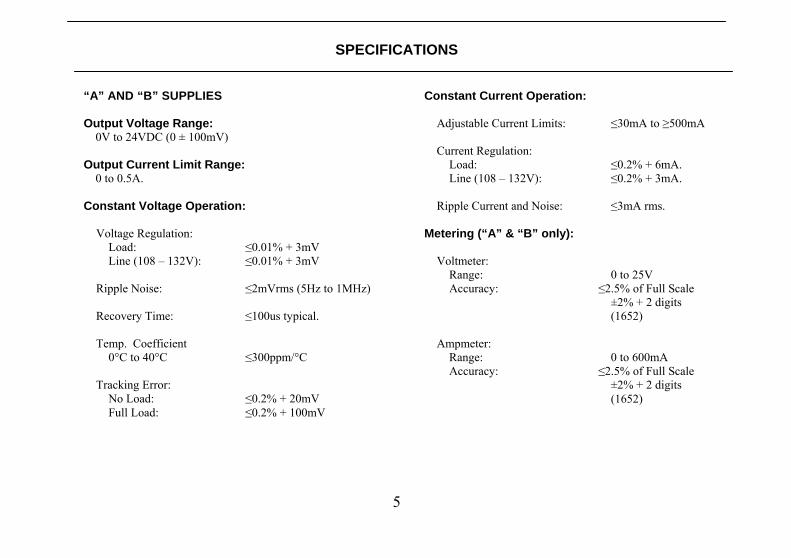
“A” AND “B” SUPPLIES Output Voltage Range:
0V to 24VDC (0 ± 100mV)
Output Current Limit Range: 0 to 0.5A.
Constant Voltage Operation: Voltage Regulation: Load: ≤0.01% + 3mV Line (108 – 132V): ≤0.01% + 3mV Ripple Noise: ≤2mVrms (5Hz to 1MHz) Recovery Time: ≤100us typical. Temp. Coefficient 0°C to 40°C ≤300ppm/°C Tracking Error: No Load: ≤0.2% + 20mV Full Load: ≤0.2% + 100mV
Constant Current Operation: Adjustable Current Limits: ≤30mA to ≥500mA Current Regulation: Load: ≤0.2% + 6mA. Line (108 – 132V): ≤0.2% + 3mA. Ripple Current and Noise: ≤3mA rms. Metering (“A” & “B” only): Voltmeter: Range: 0 to 25V Accuracy: ≤2.5% of Full Scale ±2% + 2 digits (1652) Ampmeter: Range: 0 to 600mA Accuracy: ≤2.5% of Full Scale ±2% + 2 digits (1652)
6
SPECIFICATIONS_____________________________________________________________________________________
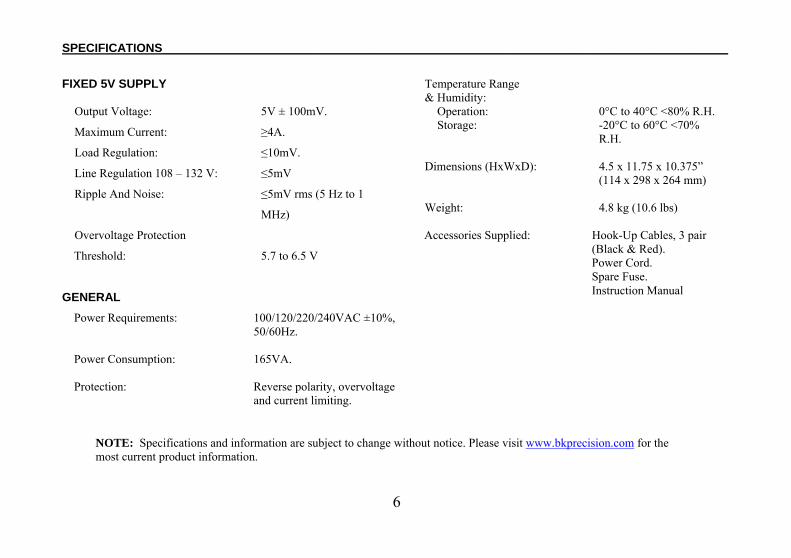
FIXED 5V SUPPLY Output Voltage: 5V ± 100mV.
Maximum Current: ≥4A.
Load Regulation: ≤10mV.
Line Regulation 108 – 132 V: ≤5mV
Ripple And Noise: ≤5mV rms (5 Hz to 1
MHz)
Overvoltage Protection
Threshold: 5.7 to 6.5 V
GENERAL Power Requirements: 100/120/220/240VAC ±10%,
50/60Hz. Power Consumption: 165VA. Protection: Reverse polarity, overvoltage
and current limiting.
Temperature Range & Humidity: Operation: 0°C to 40°C <80% R.H. Storage: -20°C to 60°C <70% R.H. Dimensions (HxWxD): 4.5 x 11.75 x 10.375” (114 x 298 x 264 mm) Weight: 4.8 kg (10.6 lbs)
Accessories Supplied: Hook-Up Cables, 3 pair (Black & Red). Power Cord. Spare Fuse. Instruction Manual
NOTE: Specifications and information are subject to change without notice. Please visit www.bkprecision.com for the most current product information.
7
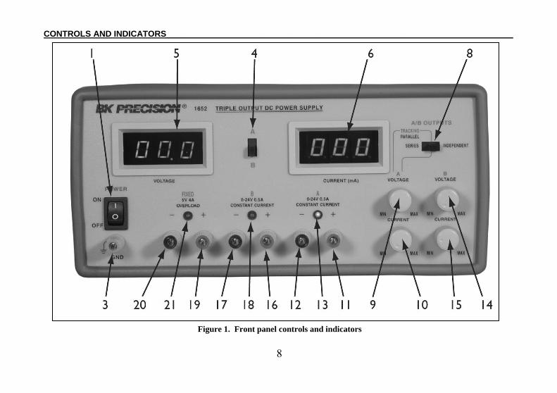
CONTROLS AND INDICATORS
1. POWER Switch. Turns power on and off. 2. Power ON light. Red LED lights to indicate a power on
condition. 3. GND Terminal (Green). Earth and Chassis Ground. 4. A/B Metering Switch. Selects simultaneous Voltage &
Current metering for the “A” or “B” supplies. When in the A position, the V and mA meters are connected to the “A” supply. When in the B position, the V and mA meters are connected to the “B” supply.
5. V Meter. Indicates voltage on the “A” or “B” supply
depending on the position of the A/B Metering switch. 6. mA Meter. Indicates current on the "A" or "B" supply
depending on the position of the A/B Metering switch. 7. Zero Adjusts. Mechanical zero adjusts for the V & mA
Meters thru the front panel with a slotted screwdriver. 8. TRACKING/INDEPENDENT Mode Switch: Three
Position switch that selects INDEPENDENT mode, PARALLEL TRACKING mode, or SERIES TRACKING mode of the “A” and “B” supplies as follows:
a. When the switch is in the right position, the unit is in the INDEPENDENT mode and the “A” and “B” power supplies are completely independent from one another.
b. When the switch is in the middle position, the unit is in the PARALLEL TRACKING mode. In this mode the “A” and “B” supplies are wired together in parallel and both the maximum current and voltage are set using the “A” controls. The “A” and “B” outputs can be used as two individual (but tracking) power supplies or just the “A” output can be used as a 0-to-24 volt supply with a 1 A capability.
c. When the switch is in the left position, the unit is in the SERIES TRACKING mode. In this mode, maximum voltage of both supplies is set using the “A” VOLTAGE controls (voltage at output terminals of the “B” supply tracks the voltage at the output terminals of the “A” supply). Also, in this mode of operation the positive terminal (red) of the “B” supply is internally connected to the negative terminal (black) of the “A” supply. This allows the two supplies to be used as one 0-to-48 volt supply.
“A” SUPPLY CONTROLS AND INDICATORS 9. VOLTAGE Control. Adjusts the output voltage of the
“A” supply. Also functions as the adjustment control for the maximum output voltage of the “B” supply when either parallel or series tracking mode is selected. Voltage can be read from the V Meter when the A Metering mode is selected.
8
CONTROLS AND INDICATORS__________________________________________________________________________ Figure 1. Front panel controls and indicators
9
__________________________________________________________________________CONTROLS AND INDICATORS
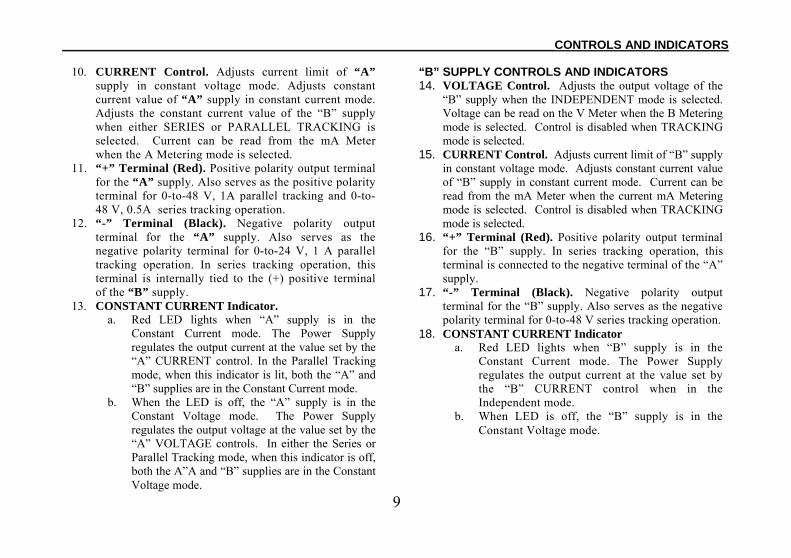
10. CURRENT Control. Adjusts current limit of “A” supply in constant voltage mode. Adjusts constant current value of “A” supply in constant current mode. Adjusts the constant current value of the “B” supply when either SERIES or PARALLEL TRACKING is selected. Current can be read from the mA Meter when the A Metering mode is selected.
11. “+” Terminal (Red). Positive polarity output terminal for the “A” supply. Also serves as the positive polarity terminal for 0-to-48 V, 1A parallel tracking and 0-to-48 V, 0.5A series tracking operation.
12. “-” Terminal (Black). Negative polarity output terminal for the “A” supply. Also serves as the negative polarity terminal for 0-to-24 V, 1 A parallel tracking operation. In series tracking operation, this terminal is internally tied to the (+) positive terminal of the “B” supply.
13. CONSTANT CURRENT Indicator. a. Red LED lights when “A” supply is in the
Constant Current mode. The Power Supply regulates the output current at the value set by the “A” CURRENT control. In the Parallel Tracking mode, when this indicator is lit, both the “A” and “B” supplies are in the Constant Current mode.
b. When the LED is off, the “A” supply is in the Constant Voltage mode. The Power Supply regulates the output voltage at the value set by the “A” VOLTAGE controls. In either the Series or Parallel Tracking mode, when this indicator is off, both the A”A and “B” supplies are in the Constant Voltage mode.
“B” SUPPLY CONTROLS AND INDICATORS14. VOLTAGE Control. Adjusts the output voltage of the
“B” supply when the INDEPENDENT mode is selected. Voltage can be read on the V Meter when the B Metering mode is selected. Control is disabled when TRACKING mode is selected.
15. CURRENT Control. Adjusts current limit of “B” supply in constant voltage mode. Adjusts constant current value of “B” supply in constant current mode. Current can be read from the mA Meter when the current mA Metering mode is selected. Control is disabled when TRACKING mode is selected.
16. “+” Terminal (Red). Positive polarity output terminal for the “B” supply. In series tracking operation, this terminal is connected to the negative terminal of the “A” supply.
17. “-” Terminal (Black). Negative polarity output terminal for the “B” supply. Also serves as the negative polarity terminal for 0-to-48 V series tracking operation.
18. CONSTANT CURRENT Indicator a. Red LED lights when “B” supply is in the
Constant Current mode. The Power Supply regulates the output current at the value set by the “B” CURRENT control when in the Independent mode.
b. When LED is off, the “B” supply is in the Constant Voltage mode.
10
CONTROLS AND INDICATORS__________________________________________________________________________
FIXED 5V SUPPLY TERMINALS AND INDICATOR 19. “+” Terminal (Red). Positive polarity output terminal
for FIXED 5V supply. 20. “-“ Terminal (Black). Negative polarity output terminal
for FIXED 5V supply. 21. OVERLOAD Indicator. Lights when load on FIXED 5
Volt supply becomes too large.
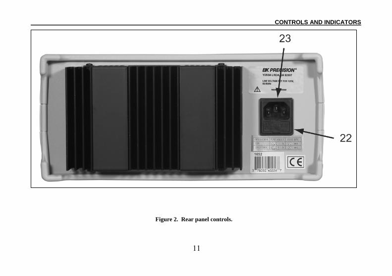
REAR PANEL CONTROLS22. LINE VOLTAGE SELECT Switches. Combination
settings allow Universal Power Operation; 23. Line Cord Receptacle. Fuse.
11
__________________________________________________________________________CONTROLS AND INDICATORS
Figure 2. Rear panel controls.
12
OPERATING INSTRUCTIONS
SAFETY PRECAUTIONS
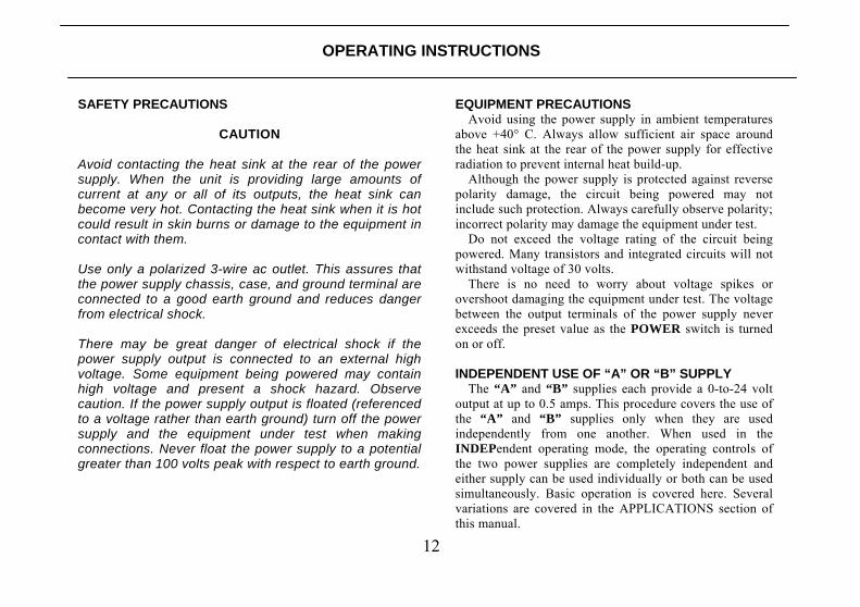
CAUTION Avoid contacting the heat sink at the rear of the power supply. When the unit is providing large amounts of current at any or all of its outputs, the heat sink can become very hot. Contacting the heat sink when it is hot could result in skin burns or damage to the equipment in contact with them. Use only a polarized 3-wire ac outlet. This assures that the power supply chassis, case, and ground terminal are connected to a good earth ground and reduces danger from electrical shock. There may be great danger of electrical shock if the power supply output is connected to an external high voltage. Some equipment being powered may contain high voltage and present a shock hazard. Observe caution. If the power supply output is floated (referenced to a voltage rather than earth ground) turn off the power supply and the equipment under test when making connections. Never float the power supply to a potential greater than 100 volts peak with respect to earth ground.
EQUIPMENT PRECAUTIONSAvoid using the power supply in ambient temperatures
above +40° C. Always allow sufficient air space around the heat sink at the rear of the power supply for effective radiation to prevent internal heat build-up.
Although the power supply is protected against reverse polarity damage, the circuit being powered may not include such protection. Always carefully observe polarity; incorrect polarity may damage the equipment under test.
Do not exceed the voltage rating of the circuit being powered. Many transistors and integrated circuits will not withstand voltage of 30 volts.
There is no need to worry about voltage spikes or overshoot damaging the equipment under test. The voltage between the output terminals of the power supply never exceeds the preset value as the POWER switch is turned on or off. INDEPENDENT USE OF “A” OR “B” SUPPLY
The “A” and “B” supplies each provide a 0-to-24 volt output at up to 0.5 amps. This procedure covers the use of the “A” and “B” supplies only when they are used independently from one another. When used in the INDEPendent operating mode, the operating controls of the two power supplies are completely independent and either supply can be used individually or both can be used simultaneously. Basic operation is covered here. Several variations are covered in the APPLICATIONS section of this manual.
13
___________________________________________________________________________OPERATING INSTRUCTIONS
Hook-up
3. Set the INDEPENDENT/TRACKING mode switch to the right position so that the power supply is in the INDEPendent operating mode.
4. Set the A/B Metering selection switch to the A (up) position to monitor the “A” supply.
5. Turn off the power supply and the equipment to be powered during hook-up.
6. Connect the positive polarity of the device being powered to the red (+) terminal of the power supply.
7. Connect the negative polarity of the device being powered to the black (-) terminal of the power supply.
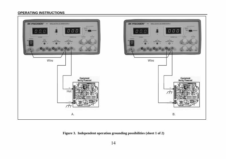
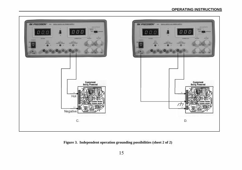
8. Fig. 3 illustrates the grounding possibilities when used in the INDEPendent mode. a. If the negative polarity of the equipment or circuit
being powered is also the chassis or common, it may be grounded to earth by strapping the black (-) terminal to the green (GND) terminal as shown in Fig. 3A.
b. Similarly, the positive polarity can be grounded by strapping the red (+) terminal to the green (GND) terminal as shown in Fig. 3B.
c. If an earth ground reference is not required, the configuration of Fig. 3C may be used. The scheme in Fig. 3C should also be used where it is not known whether the chassis is common with either the positive or negative polarity.
d. If the chassis or common of the equipment being powered is separate from both the positive and negative polarity power inputs, use the connection shown in Fig. 3D.
1. Observe proper polarity. If the circuit being powered is not equipped with reverse polarity protection, damage to the circuit can result from reverse polarity. Use color coded hook-up leads, for convenience in identifying polarity, red for (+) and black for (-).
2. Make sure that the hook-up leads offer sufficient current capability and low resistance between the power supply and the circuits being powered. The hook-up leads supplied with the power supply are rated for 4 amp.
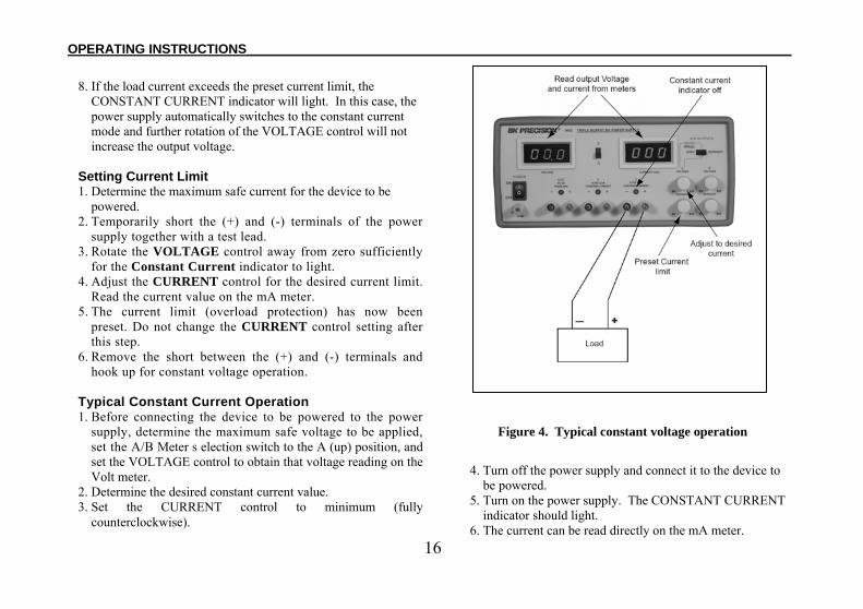
Typical Constant Voltage Operation
1. Before connecting the device to be powered to the power supply, determine the maximum safe load current for the device to be powered and set the current limit value (see “Setting Current Limit” procedure in this section).
2. Set the A/B Meter selection switch to the A (up) position to monitor the “A” supply.
3. Set VOLTAGE control to minimum (fully counterclockwise).
4. Turn off power supply and connect it to the device to be powered (see “Hook-Up” procedure in this section).
5. Turn on POWER switch. The CONSTANT CURRENT indicator should not light.
6. Increase the VOLTAGE setting until the Volt meter reads the desired value.
7. The load current is read directly on the mA meter.
14
OPERATING INSTRUCTIONS___________________________________________________________________________
Figure 3. Independent operation grounding possibilities (sheet 1 of 2)
15
___________________________________________________________________________OPERATING INSTRUCTIONS
Figure 3. Independent operation grounding possibilities (sheet 2 of 2)
16
OPERATING INSTRUCTIONS___________________________________________________________________________
8. If the load current exceeds the preset current limit, the CONSTANT CURRENT indicator will light. In this case, the power supply automatically switches to the constant current mode and further rotation of the VOLTAGE control will not increase the output voltage.
Setting Current Limit 1. Determine the maximum safe current for the device to be
powered. 2. Temporarily short the (+) and (-) terminals of the power
supply together with a test lead. 3. Rotate the VOLTAGE control away from zero sufficiently
for the Constant Current indicator to light. 4. Adjust the CURRENT control for the desired current limit.
Read the current value on the mA meter. 5. The current limit (overload protection) has now been
preset. Do not change the CURRENT control setting after this step.
6. Remove the short between the (+) and (-) terminals and hook up for constant voltage operation.
Typical Constant Current Operation 1. Before connecting the device to be powered to the power
supply, determine the maximum safe voltage to be applied, set the A/B Meter s election switch to the A (up) position, and set the VOLTAGE control to obtain that voltage reading on the Volt meter.
2. Determine the desired constant current value. 3. Set the CURRENT control to minimum (fully
counterclockwise).
Figure 4. Typical constant voltage operation
4. Turn off the power supply and connect it to the device to be powered.
5. Turn on the power supply. The CONSTANT CURRENT indicator should light.
6. The current can be read directly on the mA meter.
17
__________________________________________________________________________OPERATING INSTRUCTIONS
Figure 5. Setting Current limit.
Figure 6. Typical constant current operation.
7. Increase the CURRENT control setting until the desired constant current value is read on the display, or set the current limit in advance (before connecting the load) as prescribed earlier in the “Setting Current Limit” procedure.
8. If the load current drops below the constant current value, the CONSTANT CURRENT indicator will go off. In this case, the power supply automatically switches to the constant voltage mode, and further rotation of the CURRENT control will not increase the output current.
18
OPERATING INSTRUCTIONS___________________________________________________________________________
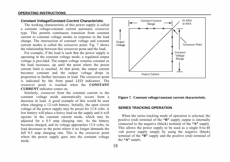
Constant Voltage/Constant Current Characteristic The working characteristic of this power supply is called
a constant voltage/constant current automatic crossover type. This permits continuous transition from constant current to constant voltage modes in response to the load change. The intersection of constant voltage and constant current modes is called the crossover point. Fig. 7 shows the relationship between this crossover point and the load.
For example, if the load is such that the power supply is operating in the constant voltage mode, a regulated output voltage is provided. The output voltage remains constant as the load increases, up until the point where the preset current limit is reached. At that point, the output current becomes constant and the output voltage drops in proportion to further increases in load. The crossover point is indicated by the front panel LED indicators. The crossover point is reached when the CONSTANT CURRENT indicator comes on.
Similarly, crossover from the constant current to the constant voltage mode automatically occurs from a decrease in load. A good example of this would be seen when charging a 12-volt battery. Initially, the open circuit voltage of the power supply may be preset for 13.8 volts. A low battery will place a heavy load on the supply and it will operate in the constant current mode, which may be adjusted for a 0.5 amp charging rate. As the battery becomes charged, and its voltage approaches 13.8 volts, its load decreases to the point where it no longer demands the full 0.5 amp charging rate. This is the crossover point where the power supply goes into the constant voltage mode.
Figure 7. Constant voltage/constant current characteristic.
SERIES TRACKING OPERATION
When the series tracking mode of operation is selected, the positive (red) terminal of the “B” supply output is internally connected to the negative (black) terminal of the “A” supply. This allows the power supply to be used as a single 0-to-48 volt power supply simply by using the negative (black) terminal of the “B” supply and the positive (red) terminal of the “A” supply.
19
__________________________________________________________________________OPERATING INSTRUCTIONS
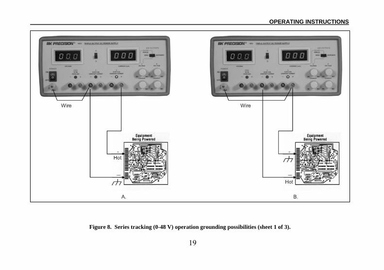
Figure 8. Series tracking (0-48 V) operation grounding possibilities (sheet 1 of 3).
20
OPERATING INSTRUCTIONS___________________________________________________________________________
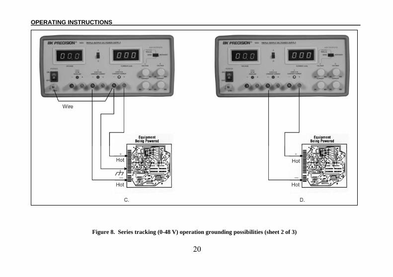
Figure 8. Series tracking (0-48 V) operation grounding possibilities (sheet 2 of 3)
21
__________________________________________________________________________OPERATING INSTRUCTIONS
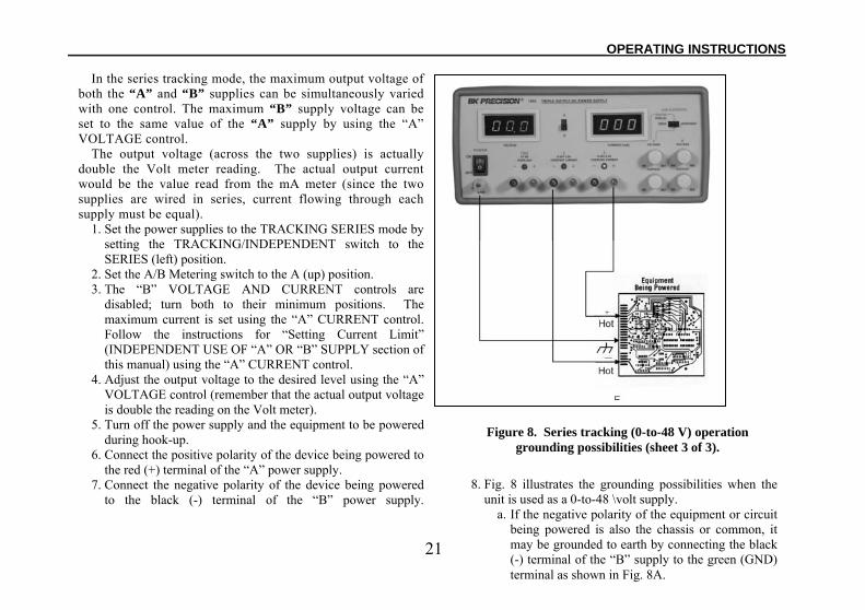
In the series tracking mode, the maximum output voltage of both the “A” and “B” supplies can be simultaneously varied with one control. The maximum “B” supply voltage can be set to the same value of the “A” supply by using the “A” VOLTAGE control.
The output voltage (across the two supplies) is actually double the Volt meter reading. The actual output current would be the value read from the mA meter (since the two supplies are wired in series, current flowing through each supply must be equal).
1. Set the power supplies to the TRACKING SERIES mode by setting the TRACKING/INDEPENDENT switch to the SERIES (left) position.
2. Set the A/B Metering switch to the A (up) position. 3. The “B” VOLTAGE AND CURRENT controls are
disabled; turn both to their minimum positions. The maximum current is set using the “A” CURRENT control. Follow the instructions for “Setting Current Limit” (INDEPENDENT USE OF “A” OR “B” SUPPLY section of this manual) using the “A” CURRENT control.
4. Adjust the output voltage to the desired level using the “A” VOLTAGE control (remember that the actual output voltage is double the reading on the Volt meter).
5. Turn off the power supply and the equipment to be powered during hook-up.
6. Connect the positive polarity of the device being powered to the red (+) terminal of the “A” power supply.
7. Connect the negative polarity of the device being powered to the black (-) terminal of the “B” power supply.
Figure 8. Series tracking (0-to-48 V) operation grounding possibilities (sheet 3 of 3).
8. Fig. 8 illustrates the grounding possibilities when the unit is used as a 0-to-48 \volt supply.
a. If the negative polarity of the equipment or circuit being powered is also the chassis or common, it may be grounded to earth by connecting the black (-) terminal of the “B” supply to the green (GND) terminal as shown in Fig. 8A.
22
OPERATING INSTRUCTIONS___________________________________________________________________________
b. Similarly, the positive polarity can be grounded by strapping the red (+) terminal of the “A” supply to the green (GND) terminal as shown in Fig. 8B.
c. If “split supply” operation is desired, a positive and negative voltage with a center ground can be achieved by strapping the black (-) terminal of the “A” supply to the green (GND) as shown in Fig. 8C. See the APPLICATIONS section of this manual for more information on “split supply” operation.
d. If an earth ground reference is not required, the configuration of Fig. 8D may be used. The scheme in Fig. 8D should also be used where it is not known whether the chassis is common with either the positive or negative polarity.
e. If the chassis or common of the equipment being powered is separate from both the positive and negative polarity power inputs, use the connection shown in Fig. 8E.
9. Observe proper polarity. If the circuit being powered is not equipped with reverse polarity protection, damage to the circuit can result from reverse polarity. Use color coded hook-up leads, for convenience in identifying polarity, red for (+) and black for (-).
10. Make sure that the hook-up leads offer sufficient current capability and low resistance between the power supply and the circuits being powered. The hook-up leads supplied with the power supply are rated for 4 amps.
PARALLEL TRACKING OPERATION In the parallel tracking mode of operation, both supplies are strapped together (in parallel). This allows for a 0-24 V supply with a 1 amp current capability. Only the “A”
output terminals are used for parallel tracking operation. In the parallel tracking mode, the “B” supply output voltage and current track the “A” supply output voltage and current. 1. Set the power supplies t TRACKING PARALLEL mode
by setting the TRACKING/INDEPENDENT switch to the PARALLEL (middle) position.
2. Set the A/B Metering switch to the A (up) position. Output voltage will be read from the Volt meter. Output current is exactly DOUBLE the value read from the mA meter (because each supply is providing the same amount of current).
3. The “B” VOLTAGE and CURRENT controls are disabled; turn both to their minimum positions. The maximum current and voltage are set using the “A” controls. Using the “A” supply output jacks, follow the instructions for “Setting Current Limit” (INDEPENDENT USE OF “A” OR “B” SUPPLY paragraph of this section). Remember that the actual current output at the “A” supply output jacks is double the reading on the mA meter.
4. Adjust the output voltage to the desired level using the “A” VOLTAGE control.
5. Turn off the power supply and the equipment to be powered during hook-up.
6. Connect the positive polarity of the device being powered to the red (+) terminal of the “A” power supply.
7. Connect the negative polarity of the device being powered to the black (-) terminal of the “A” power supply.
8. Fig. 9 illustrates the grounding possibilities when used in the TRACKING PARALLEL mode.
23
__________________________________________________________________________OPERATING INSTRUCTIONS
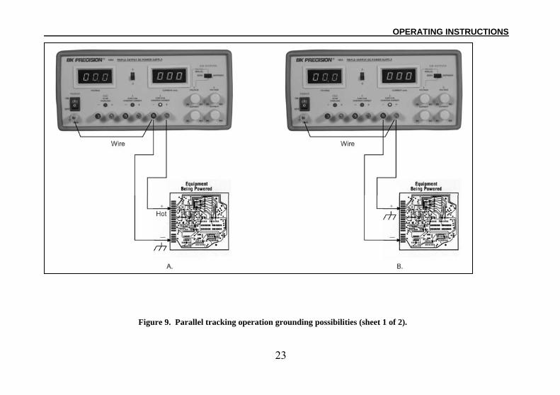
Figure 9. Parallel tracking operation grounding possibilities (sheet 1 of 2).
24
OPERATING INSTRUCTIONS___________________________________________________________________________
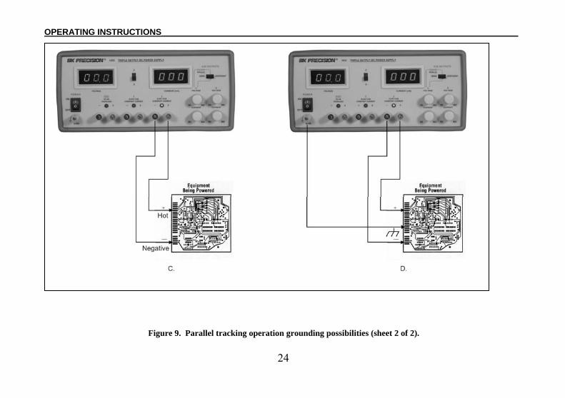
Figure 9. Parallel tracking operation grounding possibilities (sheet 2 of 2).
25
__________________________________________________________________________OPERATING INSTRUCTIONS
a. If the negative polarity of the equipment or circuit being powered is also the chassis or common, it may be grounded to earth by strapping the black (-) terminal to the green (GND) terminal as shown in Fig. 9A.
b. Similarly, the positive polarity can be grounded by strapping the red (+) terminal to the green (GN D) terminal as shown in Fig. 9B.
c. If an earth ground reference is not required, the configuration of Fig. 9C may be used. The scheme in Fig. 9C should also be used where it is not known whether the chassis is common with either the positive or negative polarity.
d. If the chassis or common of the equipment being powered is separate from both the positive and negative polarity power inputs, use the connection shown in Fig. 9D.
9. Observe proper polarity. If the circuit being powered is not equipped with reverse polarity protection, damage to the circuit can result from reverse polarity. Use color coded hook-up leads, for convenience in identifying polarity, red for (+) and black for (-).
10. Make sure that the hook-up leads offer sufficient current capability and low resistance between the power supply and the circuits being powered. The hook-up leads supplied with the power supply are rated for 4 amps.
FIXED 5 V POWER SUPPLY OPERATION The FIXED 5 V supply provides a 4 amp current capacity. The supply is ideal for use with TTL circuits.
1. Turn off the power supply and the equipment to be powered during hook-up.
2. Connect the positive polarity of the device being powered to the red (+) terminal of the FIXED 5 V supply.
3. Connect the negative polarity of the device being powered to the black (-) terminal of the FIXED 5 V supply.
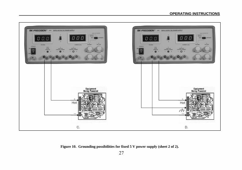
4. Fig. 10 illustrates the grounding possibilities of the FIXED 5 V supply.
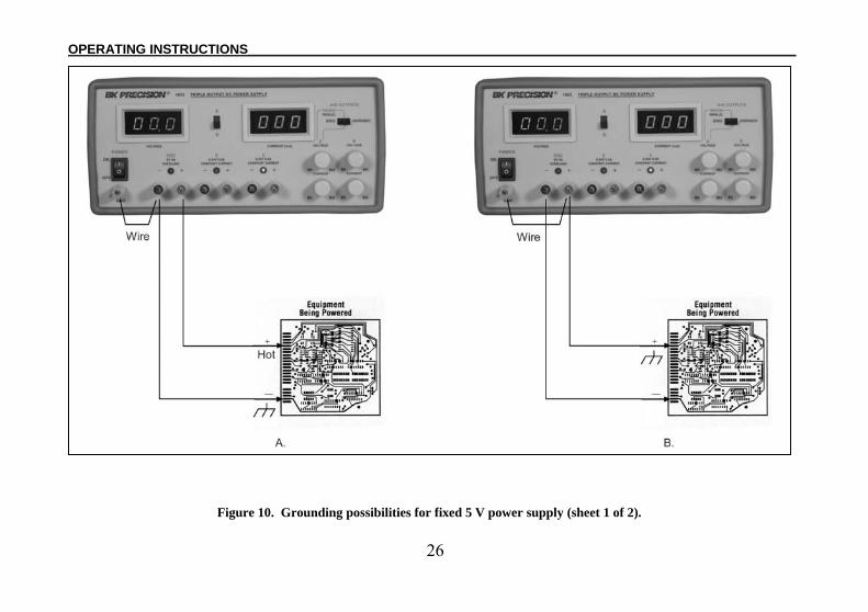
a. If the negative polarity of the equipment or circuit being powered is also the chassis or common, it may be grounded to earth by connecting the black (-) terminal to the green (GND) terminal as shown in Fig. 10A.
b. Similarly, the positive polarity can be grounded by connecting a jumper between the red (+) terminal and either green (GND) terminal as shown in Fig. 10B.
c. If an earth ground reference is not required, the configuration of Fig. 10C may be used. The scheme in Fig. 10C should also be used where it is not known whether the chassis is common with either the positive or negative polarity.
d. If the chassis or common of the equipment being powered is separate from both the positive and negative polarity power inputs, use the connection shown in Fig. 10D.
5. Observe proper polarity. If the circuit being powered is not equipped with reverse polarity protection, damage to the circuit can result from reverse polarity. Use color coded hook-up leads, such as the sets supplied with the power supply, for convenience in identifying polarity, red for (+) and black for (-).
26
OPERATING INSTRUCTIONS___________________________________________________________________________
Figure 10. Grounding possibilities for fixed 5 V power supply (sheet 1 of 2).
27
__________________________________________________________________________OPERATING INSTRUCTIONS Figure 10. Grounding possibilities for fixed 5 V power supply (sheet 2 of 2).
28
OPERATING INSTRUCTIONS___________________________________________________________________________
6. Make sure that the hook-up leads offer sufficient current capability and low resistance between the power supply and the circuits being powered. The hook-up leads supplied with the power supply are rated for 4 amps.
7. If the red OVERLOAD indicator lights, too much load has been placed on the supply. This will cause voltage and current to drop and prevent proper operation of the FIXED 5 V supply. To correct this situation, the load on the supply much be decreased so that no more than 4 amps of current are required.
NOTEIf decreasing the load does not cause the overload indicator to turn off, the overvoltage protection circuitry has turned on. In order to return the supply to normal operation, the output voltage must be decreased (or the external voltage source must be removed) and the power must be momentarily shut off.

29
APPLICATIONS
GENERALThe Model 1651A power supply has a very wide variety of
applications in electrical and electronics servicing, engineering laboratories, manufacturing and testing facilities, schools, and home hobbying. The “A” and “B” power supply outputs are fully adjustable from 0-to-24 volts and 0-to-0.5 amps and the FIXED 5 V supply has a current capability of 0-to-4 amps. This flexibility makes it suitable for most applications requiring a dc power source. ELECTRONICS SERVICING
Most electronics troubleshooting and repair is performed on a test bench. This power supply can provide the dc power source to operate a module or circuit board on the test bench when it is removed from its parent equipment. It can be used to power portable, battery-operated equipment and check the effect of low battery voltage. It can power some vehicular equipment such as tape players, auto sound systems, CB radios, etc. on the test bench. Parallel tracking supplies up to 1 amp.
Most automobiles and other vehicles use 12-volt electrical systems. Although the electrical system is normally referred to as a 12-volt system, actual battery voltage when fully charged is approximately 13.8 volts. The power supply may be set to 13.8 volts for servicing equipment from vehicles with 12-volt electrical systems. Some trucks use a 24-volt electrical system; bench testing of equipment from these systems should be performed at approximately 28 volts.
Some servicing applications require the injection of a variable dc voltage for certain tests, such as checking the effect of AGC bias in a television receiver. This requires an isolated dc power supply, such as the Model 1651A. The equipment being tested may contain its own power supply and operate from ac power. A dc voltage may already be present in the circuit. One polarity of the power supply output is floated to an appropriate point in the circuit, such as the emitter of a transistor. The other polarity of the power supply output is then applied to another point in the circuit, such as the base of that transistor. Varying the power supply voltage then varies the dc bias on the stage, and the effects may be noted. A series limiting resistor is often used to protect the circuits from overdissipation. ELECTRONICS MANUFACTURING
In electronics manufacturing facilities, the power supply is often used as a dc power source while testing and adjusting modules, subassemblies, and complete units in the production and assembly area or in the quality control area. The instrument can be used in incoming inspection as a dc power source for testing purchased components and subassemblies.
This power supply is particularly well suited for manufacturing applications because of its ease of operation and its continuous duty rating. When load current or total power dissipation are among the main characteristics to be measured, the total load current and voltage are simultaneously displayed on the panel meters. The current limit can be set so that all units which do not meet the load current specification will cause the CONSTANT CURRENT indicator to light, and the unit can be rejected.
30
APPLICATIONS_______________________________________________________________________________________
ELECTRONICS DESIGN LABThe technician or engineer working in an engineering
laboratory requires a dc power supply to power breadboard and prototype circuits. This power supply is ideal because it monitors output current and voltage, limits current to protect the circuit, is adjustable over a wide range, and has excellent regulation and very low ripple.
Use of the instrument in an engineering laboratory is very similar to that described for servicing electronics equipment and modules, except that lower currents may be prevalent when powering individual circuits. The current limiting feature is very valuable in this application because it can protect unproven circuits from damage. ELECTRONICS EDUCATION
The student in an electronics curriculum may use the power supply for powering equipment and circuits as previously described for all other applications. In addition, the power supply can be used in the classroom laboratory to conduct experiments in fundamental electronics. In learning Ohm’s law, for example, the relationships of resistance, current, and voltage are easily demonstrated by the use of a power supply. BATTERY CHARGING
The power supply can be used as a battery charger to restore the charge in rechargeable batteries such as lead-acid, nickel-cadmium, and some alkaline types. Refer to the battery manufacturer’s charging specifications for proper voltage and current settings.
Charging information is sometimes printed on the batteries. Battery charging, at least initially, requires the constant current mode of operation. Before connecting the power supply to the battery, preset the VOLTAGE controls to the fully charged terminal voltage specified by the battery manufacturer. Turn off the power supply while connecting the battery. Observe proper polarity and connect as for constant current operation. Adjust the CURRENT control for the maximum charging current specified by the battery manufacturer (If the maximum charging current is greater than the power supply’s maximum load current, set the CURRENT control to maximum). The CONSTANT CURRENT indicator will light and the battery will charge at the preset current limit. As the battery approaches full charge, its terminal voltage will approach that of the power supply output and the charging current will taper off. The power supply may automatically switch to constant voltage operation. When this occurs, the power supply will continue to provide a trickle charge. SPLIT SUPPLY
Frequently, “split power supplies” are required for amplifiers and other electronic circuits. The Model 1651A is ideally suited for “split power supply” operation. This supply can be configured to provide two positive voltages with a common negative, two negative voltages with a common positive, or one positive and one negative with a common ground. In addition, each of these configurations can be obtained with identical or differing voltages.
31
_______________________________________________________________________________________APPLICATIONS
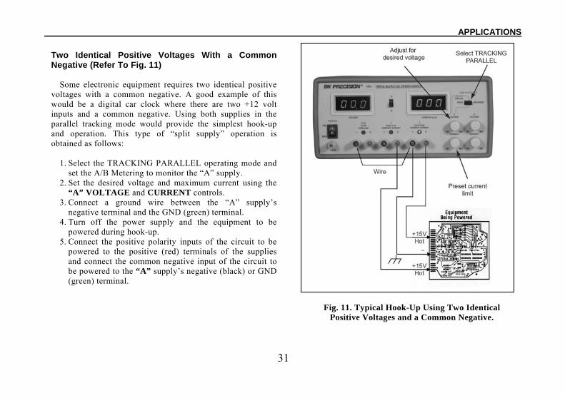
Two Identical Positive Voltages With a Common Negative (Refer To Fig. 11)
Some electronic equipment requires two identical positive voltages with a common negative. A good example of this would be a digital car clock where there are two +12 volt inputs and a common negative. Using both supplies in the parallel tracking mode would provide the simplest hook-up and operation. This type of “split supply” operation is obtained as follows:
1. Select the TRACKING PARALLEL operating mode and set the A/B Metering to monitor the “A” supply.
2. Set the desired voltage and maximum current using the “A” VOLTAGE and CURRENT controls.
3. Connect a ground wire between the “A” supply’s negative terminal and the GND (green) terminal.
4. Turn off the power supply and the equipment to be powered during hook-up.
5. Connect the positive polarity inputs of the circuit to be powered to the positive (red) terminals of the supplies and connect the common negative input of the circuit to be powered to the “A” supply’s negative (black) or GND (green) terminal.
Fig. 11. Typical Hook-Up Using Two Identical
Positive Voltages and a Common Negative.
32
APPLICATIONS_______________________________________________________________________________________
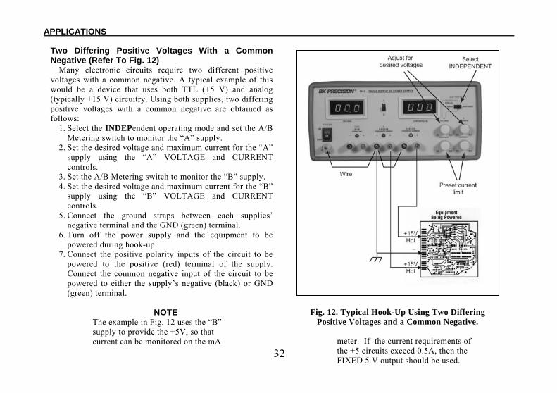
Two Differing Positive Voltages With a Common Negative (Refer To Fig. 12)
Many electronic circuits require two different positive voltages with a common negative. A typical example of this would be a device that uses both TTL (+5 V) and analog (typically +15 V) circuitry. Using both supplies, two differing positive voltages with a common negative are obtained as follows:
1. Select the INDEPendent operating mode and set the A/B Metering switch to monitor the “A” supply.
2. Set the desired voltage and maximum current for the “A” supply using the “A” VOLTAGE and CURRENT controls.
3. Set the A/B Metering switch to monitor the “B” supply. 4. Set the desired voltage and maximum current for the “B”
supply using the “B” VOLTAGE and CURRENT controls.
5. Connect the ground straps between each supplies’ negative terminal and the GND (green) terminal.
6. Turn off the power supply and the equipment to be powered during hook-up.
7. Connect the positive polarity inputs of the circuit to be powered to the positive (red) terminal of the supply. Connect the common negative input of the circuit to be powered to either the supply’s negative (black) or GND (green) terminal.
NOTE
The example in Fig. 12 uses the “B” supply to provide the +5V, so that current can be monitored on the mA
Fig. 12. Typical Hook-Up Using Two Differing Positive Voltages and a Common Negative.
meter. If the current requirements of the +5 circuits exceed 0.5A, then the FIXED 5 V output should be used.
33
_______________________________________________________________________________________APPLICATIONS
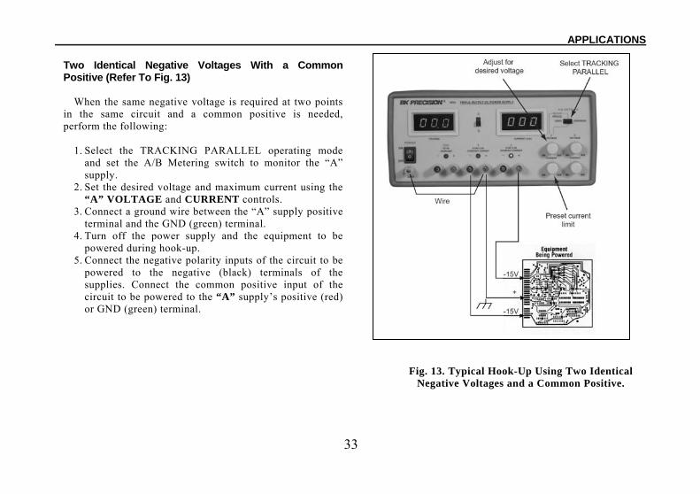
Two Identical Negative Voltages With a Common Positive (Refer To Fig. 13)
When the same negative voltage is required at two points in the same circuit and a common positive is needed, perform the following:
1. Select the TRACKING PARALLEL operating mode and set the A/B Metering switch to monitor the “A” supply.
2. Set the desired voltage and maximum current using the “A” VOLTAGE and CURRENT controls.
3. Connect a ground wire between the “A” supply positive terminal and the GND (green) terminal.
4. Turn off the power supply and the equipment to be powered during hook-up.
5. Connect the negative polarity inputs of the circuit to be powered to the negative (black) terminals of the supplies. Connect the common positive input of the circuit to be powered to the “A” supply’s positive (red) or GND (green) terminal.
Fig. 13. Typical Hook-Up Using Two Identical Negative Voltages and a Common Positive.
34
APPLICATIONS_______________________________________________________________________________________
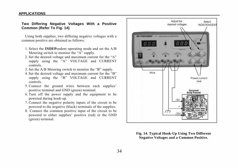
Two Differing Negative Voltages With a Positive Common (Refer To Fig. 14)
Using both supplies, two differing negative voltages with a common positive are obtained as follows:
1. Select the INDEPendent operating mode and set the A/B Metering switch to monitor the “A” supply.
2. Set the desired voltage and maximum current for the “A” supply using the “A” VOLTAGE and CURRENT controls.
3. Set the A/B Metering switch to monitor the “B” supply. 4. Set the desired voltage and maximum current for the “B”
supply using the “B” VOLTAGE and CURRENT controls.
5. Connect the ground wires between each supplies’ positive terminal and GND (green) terminal.
6. Turn off the power supply and the equipment to be powered during hook-up.
7. Connect the negative polarity inputs of the circuit to be powered to the negative (black) terminals of the supplies.
8. Connect the common positive input of the circuit to be powered to either supplies’ positive (red) or the GND (green) terminal.
Fig. 14. Typical Hook-Up Using Two Different Negative Voltages and a Common Positive.
35
_______________________________________________________________________________________APPLICATIONS
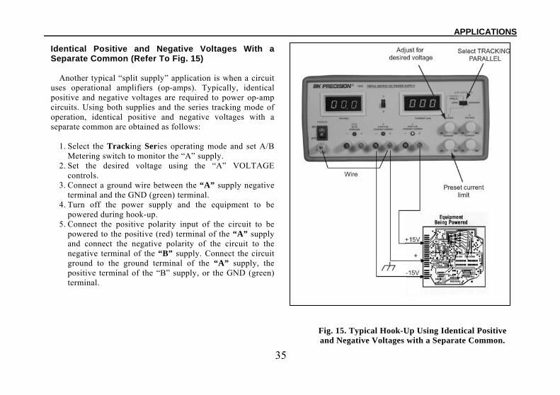
Identical Positive and Negative Voltages With a Separate Common (Refer To Fig. 15)
Another typical “split supply” application is when a circuit uses operational amplifiers (op-amps). Typically, identical positive and negative voltages are required to power op-amp circuits. Using both supplies and the series tracking mode of operation, identical positive and negative voltages with a separate common are obtained as follows:
1. Select the Tracking Series operating mode and set A/B Metering switch to monitor the “A” supply.
2. Set the desired voltage using the “A” VOLTAGE controls.
3. Connect a ground wire between the “A” supply negative terminal and the GND (green) terminal.
4. Turn off the power supply and the equipment to be powered during hook-up.
5. Connect the positive polarity input of the circuit to be powered to the positive (red) terminal of the “A” supply and connect the negative polarity of the circuit to the negative terminal of the “B” supply. Connect the circuit ground to the ground terminal of the “A” supply, the positive terminal of the “B” supply, or the GND (green) terminal.
Fig. 15. Typical Hook-Up Using Identical Positive and Negative Voltages with a Separate Common.
36
APPLICATIONS_______________________________________________________________________________________
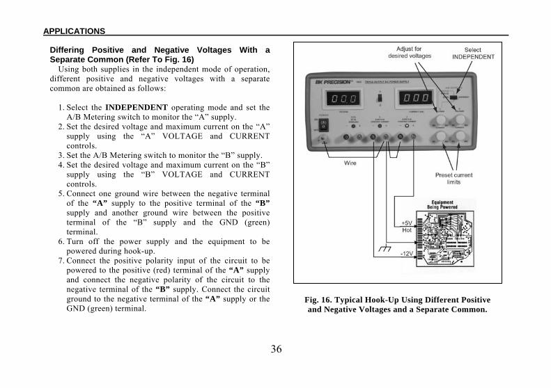
Differing Positive and Negative Voltages With a Separate Common (Refer To Fig. 16)
Using both supplies in the independent mode of operation, different positive and negative voltages with a separate common are obtained as follows:
1. Select the INDEPENDENT operating mode and set the
A/B Metering switch to monitor the “A” supply. 2. Set the desired voltage and maximum current on the “A”
supply using the “A” VOLTAGE and CURRENT controls.
3. Set the A/B Metering switch to monitor the “B” supply. 4. Set the desired voltage and maximum current on the “B”
supply using the “B” VOLTAGE and CURRENT controls.
5. Connect one ground wire between the negative terminal of the “A” supply to the positive terminal of the “B” supply and another ground wire between the positive terminal of the “B” supply and the GND (green) terminal.
6. Turn off the power supply and the equipment to be powered during hook-up.
7. Connect the positive polarity input of the circuit to be powered to the positive (red) terminal of the “A” supply and connect the negative polarity of the circuit to the negative terminal of the “B” supply. Connect the circuit ground to the negative terminal of the “A” supply or the GND (green) terminal.
Fig. 16. Typical Hook-Up Using Different Positive and Negative Voltages and a Separate Common.
37
MAINTENANCE
WARNINGThe following instructions are for use by qualified personnel only. To avoid electrical shock, do not perform any servicing other than contained in the operating instructions unless you are qualified to do so.
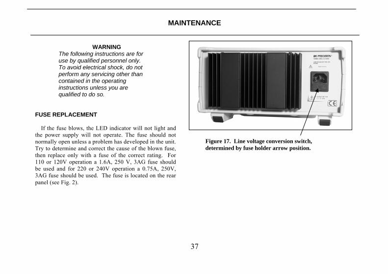
FUSE REPLACEMENT If the fuse blows, the LED indicator will not light and the power supply will not operate. The fuse should not normally open unless a problem has developed in the unit. Try to determine and correct the cause of the blown fuse, then replace only with a fuse of the correct rating. For 110 or 120V operation a 1.6A, 250 V, 3AG fuse should be used and for 220 or 240V operation a 0.75A, 250V, 3AG fuse should be used. The fuse is located on the rear panel (see Fig. 2).
Figure 17. Line voltage conversion switch, determined by fuse holder arrow position.

38
Service Information Warranty Service: Please return the product in the original packaging with proof of purchase to the address below. Clearly state in writing the performance problem and return any leads, probes, connectors and accessories that you are using with the device. Non-Warranty Service: Return the product in the original packaging to the address below. Clearly state in writing the performance problem and return any leads, probes, connectors and accessories that you are using with the device. Customers not on open account must include payment in the form of a money order or credit card. For the most current repair charges please visit www.bkprecision.com and click on “service/repair”. Return all merchandise to B&K Precision Corp. with pre-paid shipping. The flat-rate repair charge for Non-Warranty Service does not include return shipping. Return shipping to locations in North American is included for Warranty Service. For overnight shipments and non-North American shipping fees please contact B&K Precision Corp.
B&K Precision Corp. 22820 Savi Ranch Parkway
Yorba Linda, CA 92887 www.bkprecision.com
714-921-9095 Include with the returned instrument your complete return shipping address, contact name, phone number and description of problem.

39
Limited One-Year Warranty B&K Precision Corp. warrants to the original purchaser that its products and the component parts thereof, will be free from defects in workmanship and materials for a period of one year from date of purchase. B&K Precision Corp. will, without charge, repair or replace, at its option, defective product or component parts. Returned product must be accompanied by proof of the purchase date in the form of a sales receipt. To obtain warranty coverage in the U.S.A., this product must be registered by completing a warranty registration form on www.bkprecision.com within fifteen (15) days of purchase. Exclusions: This warranty does not apply in the event of misuse or abuse of the product or as a result of unauthorized alterations or repairs. The warranty is void if the serial number is altered, defaced or removed. B&K Precision Corp. shall not be liable for any consequential damages, including without limitation damages resulting from loss of use. Some states do not allow limitations of incidental or consequential damages. So the above limitation or exclusion may not apply to you. This warranty gives you specific rights and you may have other rights, which vary from state-to-state. B&K Precision Corp. 22820 Savi Ranch Parkway Yorba Linda, CA 92887 www.bkprecision.com 714-921-9095
40
TEST INSTRUMENT SAFETY____________________________________________________________________________
(continued from inside front cover)
4. If possible, familiarize yourself with the equipment being tested and the location of its high voltage points. However, remember that high voltage may appear at unexpected points in defective equipment.
5. Use an insulated floor material or a large, insulated floor mat to stand on, and an insulated work surface on which to place equipment; and make certain such surfaces are not damp or wet.
6. Use the time-proven “one hand in the pocket” technique while handling an instrument probe. Be particularly careful to avoid contacting a nearby metal object that could provide a good ground return path.
7. When testing ac powered equipment, remember that the ac line voltage is usually present on some power input circuits such as the on-off switch, fuses, power transformer, etc. any time the equipment is connected to an ac outlet, even if the equipment is turned off.
8. Some equipment with a two-wire ac power cord, including some with polarized power plugs, is the “hot chassis” type. This includes most recent television receivers and audio equipment. A plastic or wooden cabinet insulates the chassis to protect the customer. When the cabinet is removed for servicing, a serious shock hazard exists if the chassis is touched. Not only does this present a dangerous shock hazard, but damage to test instruments or the equipment under test may result from connecting an earth ground lead of a test instrument to a “hot chassis”. To make measurements in “hot chassis” equipment, always connect an isolation transformer between the ac outlet and the equipment under test. The B+K Precision Model TR-110 or 1604 Isolation Transformer, or Model 1653 or 1655 AC Power Supply is suitable for most applications. To be on the safe side, treat all two-wire ac powered equipment as “hot chassis” unless you are sure it has an isolated chassis or an earth ground chassis.
9. B+K Precision products are not authorized for use in any application involving direct contact between our product and the human body, or for use as a critical component in a life support device or system. Here, “direct contact” refers to any connection from or to our equipment via any cabling or switching means. A ”critical component” is any component of a life support device or system whose failure to perform can be reasonably expected to cause failure of that device or system, or to affect its safety or effectiveness.
10. Never work alone. Someone should be nearby to render aid if necessary. Training in CPR (cardio-pulmonary resuscitation) first aid is highly recommended.

41
MANUAL DE INSTRUCCIÓNES
FUENTE DE PODER DE CD TRIPLE MODELOS 1651A & 1652
22820 Savi Ranch Parkway Yorba Linda, CA 92887
www.bkprecision.com
42
SEGURIDAD DEL INSTRUMENTO DE PRUEBA
ADVERTENCIA El uso normal de equipo de prueba lo expone a un posible riesgo de choque eléctrico debido a que las pruebas pueden realizarse cuando en presencia de alto voltaje expuesto. Un choque eléctrico que permita el paso de 10mA de corriente por el corazón causará que deje de latir. Voltajes tan bajos como 35 volts DC o AC RMS considerarse como de peligro dado que pueden causar corrientes letales bajo ciertas condiciones. Voltajes mayores presentan un riesgo de corriente letal aún mayor. Sus hábitos de trabajo normales deben incluir todas las prácticas que previenen el contacto con voltajes altos expuestos, o que permiten desviar la corriente fuera del corazón en caso de contacto accidental con un voltaje alto. El factor de riesgo puede reducirse significativamente si conoce y observa las precauciones siguientes:
a) Hay poco riesgo de choque eléctrico de la salida de dc de esta fuente de poder. Sin embargo, hay condiciones de prueba posibles que pueden ocasionar un choque eléctrico de alto voltaje:
c. Si el equipo bajo prueba es del tipo de “chasis caliente”, existe un riesgo alto a menos que el equipo se desconecte de la
línea (el apagarlo no remueve el riesgo), o se observen las precauciones del paso 8. d. Si el equipo bajo prueba está encendido (y usa alto voltaje en cualquiera de sus circuitos), las salidas de la fuente pueden
exhibir un voltaje flotante respecto al punto de conexión. Recuerde que voltajes altos pueden aparecer en puntos inesperados de un equipo defectuoso. No flote la salida de la fuente a más de 100 volts pico respecto al chasis o tierra física.
e. Si el equipo bajo prueba está encendido (y usa alto voltaje en cualquiera de sus circuitos), descargue los capacitores de alto voltaje antes de efectuar conexiones o pruebas. Algunos circuitos retienen alto voltaje un tiempo largo después de apagarlos.
b) Use sólo un receptáculo de ac polarizado de 3 puntas. Esto asegura que el chasis de la fuente, el gabinete y terminal de tierra están
conectados a una buena tierra física, lo que reduce el peligro de una descarga eléctrica.
c) No se exponga a un voltaje alto sin necesidad. Remueva la cubierta sólo si es indispensable. Apague el equipo al efectuar conexiones en circuitos de alto voltaje. Descargue los capacitores de alto voltaje después de apagar.
d) De ser posible, familiarícese con el instrumento bajo prueba y la localización de sus puntos de alto voltaje. Recuerde, sin embargo,
que un voltaje alto puede aparecer en puntos inesperados en equipos defectuosos. (continua el la parte de atrás)
43
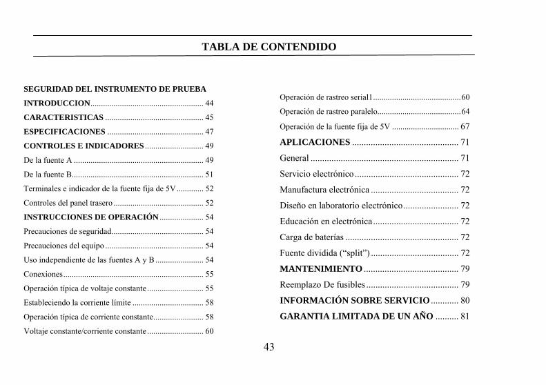
TABLA DE CONTENDIDO
SEGURIDAD DEL INSTRUMENTO DE PRUEBA
INTRODUCCION...................................................... 44
CARACTERISTICAS ............................................... 45
ESPECIFICACIONES .............................................. 47
CONTROLES E INDICADORES ............................ 49
De la fuente A .............................................................. 49
De la fuente B............................................................... 51
Terminales e indicador de la fuente fija de 5V............. 52
Controles del panel trasero ........................................... 52
INSTRUCCIONES DE OPERACIÓN ..................... 54
Precauciones de seguridad............................................ 54
Precauciones del equipo ............................................... 54
Uso independiente de las fuentes A y B ....................... 54
Conexiones................................................................... 55
Operación típica de voltaje constante ........................... 55
Estableciendo la corriente límite .................................. 58
Operación típica de corriente constante........................ 58
Voltaje constante/corriente constante ........................... 60
Operación de rastreo serial1..........................................60
Operación de rastreo paralelo........................................64
Operación de la fuente fija de 5V ................................ 67
APLICACIONES .............................................. 71
General ................................................................ 71
Servicio electrónico ............................................. 72
Manufactura electrónica ...................................... 72
Diseño en laboratorio electrónico........................ 72
Educación en electrónica..................................... 72
Carga de baterías ................................................. 72
Fuente dividida (“split”) ...................................... 72
MANTENIMIENTO ......................................... 79
Reemplazo De fusibles ........................................ 79
INFORMACIÓN SOBRE SERVICIO ............ 80
GARANTIA LIMITADA DE UN AÑO .......... 81
44
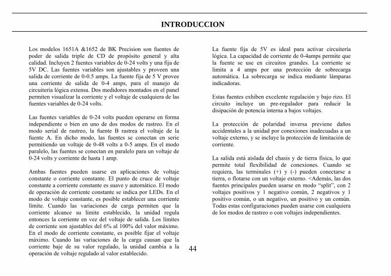
INTRODUCCION
Los modelos 1651A &1652 de BK Precision son fuentes de poder de salida triple de CD de propósito general y alta calidad. Incluyen 2 fuentes variables de 0-24 volts y una fija de 5V DC. Las fuentes variables son ajustables y proveen una salida de corriente de 0-0.5 amps. La fuente fija de 5 V provee una corriente de salida de 0-4 amps, para el manejo de circuitería lógica extensa. Dos medidores montados en el panel permiten visualizar la corriente y el voltaje de cualquiera de las fuentes variables de 0-24 volts. Las fuentes variables de 0-24 volts pueden operarse en forma independiente o bien en uno de dos modos de rastreo. En el modo serial de rastreo, la fuente B rastrea el voltaje de la fuente A. En dicho modo, las fuentes se conectan en serie permitiendo un voltaje de 0-48 volts a 0-5 amps. En el modo paralelo, las fuentes se conectan en paralelo para un voltaje de 0-24 volts y corriente de hasta 1 amp. Ambas fuentes pueden usarse en aplicaciones de voltaje constante o corriente constante. El punto de cruce de voltaje constante a corriente constante es suave y automático. El modo de operación de corriente constante se indica por LEDs. En el modo de voltaje constante, es posible establecer una corriente límite. Cuando las variaciones de carga permiten que la corriente alcance su límite establecido, la unidad regula entonces la corriente en vez del voltaje de salida. Los límites de corriente son ajustables del 6% al 100% del valor máximo. En el modo de corriente constante, es posible fijar el voltaje máximo. Cuando las variaciones de la carga causan que la corriente baje de su valor regulado, la unidad cambia a la operación de voltaje regulado al valor establecido.
La fuente fija de 5V es ideal para activar circuitería lógica. La capacidad de corriente de 0-4amps permite que la fuente se use en circuitos grandes. La corriente se limita a 4 amps por una protección de sobrecarga automática. La sobrecarga se indica mediante lámparas indicadoras. Estas fuentes exhiben excelente regulación y bajo rizo. El circuito incluye un pre-regulador para reducir la disipación de potencia interna a bajos voltajes. La protección de polaridad inversa previene daños accidentales a la unidad por conexiones inadecuadas a un voltaje externo, y se incluye la protección de limitación de corriente. La salida está aislada del chasis y de tierra física, lo que permite total flexibilidad de conexiones. Cuando se requiera, las terminales (+) y (-) pueden conectarse a tierra, o flotarse con un voltaje externo. <Además, las dos fuentes principales pueden usarse en modo “split”, con 2 voltajes positivos y 1 negativo común, 2 negativos y 1 positivo común, o un negativo, un positivo y un común. Todas estas configuraciones pueden usarse con cualquiera de los modos de rastreo o con voltajes independientes.
45
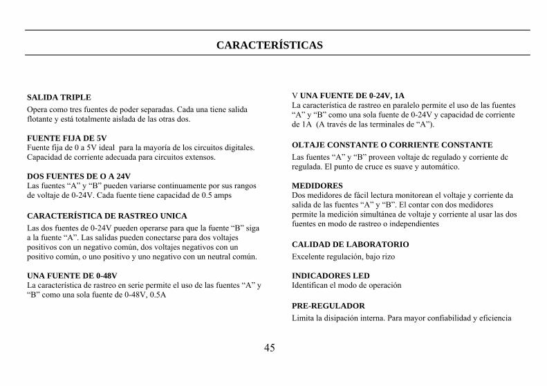
CARACTERÍSTICAS
SALIDA TRIPLE Opera como tres fuentes de poder separadas. Cada una tiene salida flotante y está totalmente aislada de las otras dos. FUENTE FIJA DE 5V Fuente fija de 0 a 5V ideal para la mayoría de los circuitos digitales. Capacidad de corriente adecuada para circuitos extensos. DOS FUENTES DE O A 24V Las fuentes “A” y “B” pueden variarse continuamente por sus rangos de voltaje de 0-24V. Cada fuente tiene capacidad de 0.5 amps
CARACTERÍSTICA DE RASTREO UNICA Las dos fuentes de 0-24V pueden operarse para que la fuente “B” siga a la fuente “A”. Las salidas pueden conectarse para dos voltajes positivos con un negativo común, dos voltajes negativos con un positivo común, o uno positivo y uno negativo con un neutral común. UNA FUENTE DE 0-48V La característica de rastreo en serie permite el uso de las fuentes “A” y “B” como una sola fuente de 0-48V, 0.5A
V UNA FUENTE DE 0-24V, 1A La característica de rastreo en paralelo permite el uso de las fuentes “A” y “B” como una sola fuente de 0-24V y capacidad de corriente de 1A (A través de las terminales de “A”).
OLTAJE CONSTANTE O CORRIENTE CONSTANTE Las fuentes “A” y “B” proveen voltaje dc regulado y corriente dc regulada. El punto de cruce es suave y automático. MEDIDORES Dos medidores de fácil lectura monitorean el voltaje y corriente da salida de las fuentes “A” y “B”. El contar con dos medidores permite la medición simultánea de voltaje y corriente al usar las dos fuentes en modo de rastreo o independientes
CALIDAD DE LABORATORIO Excelente regulación, bajo rizo INDICADORES LED Identifican el modo de operación
PRE-REGULADOR Limita la disipación interna. Para mayor confiabilidad y eficiencia
46
CARACTERÍSTICAS
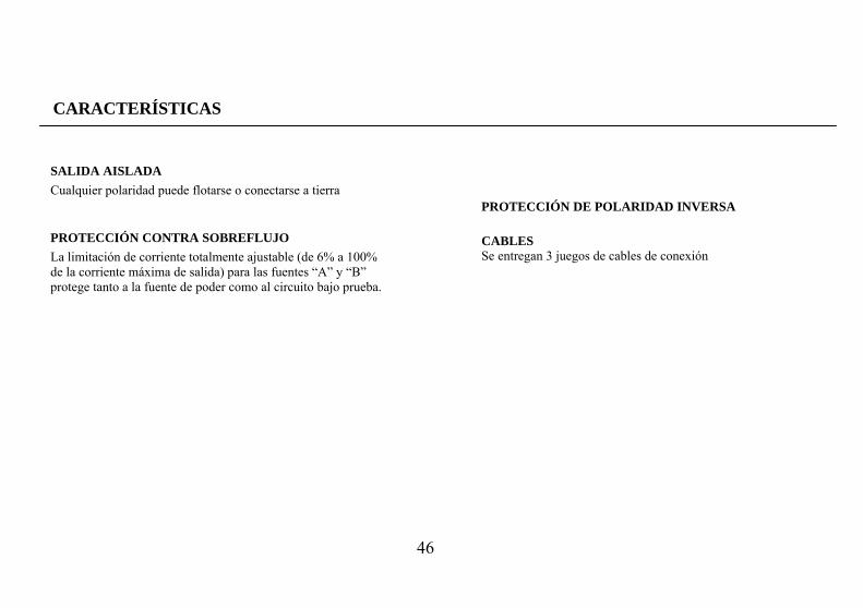
SALIDA AISLADA Cualquier polaridad puede flotarse o conectarse a tierra
PROTECCIÓN CONTRA SOBREFLUJO La limitación de corriente totalmente ajustable (de 6% a 100% de la corriente máxima de salida) para las fuentes “A” y “B” protege tanto a la fuente de poder como al circuito bajo prueba.
PROTECCIÓN DE POLARIDAD INVERSA CABLES Se entregan 3 juegos de cables de conexión
47
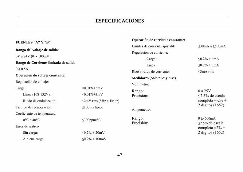
ESPECIFICACIONES
Operación de corriente constante:
Límites de corriente ajustable: ≤30mA a ≥500mA
Regulación de corriente:
Carga: ≤0.2% + 6mA
Línea ≤0.2% + 3mA
Rizo y ruido de corriente: ≤3mA rms
Medidores (Sólo “A” y “B”)
Voltímetro:
Rango: 0 a 25V Precisión: ≤2.5% de escala completa +-2% + 2 dígitos (1652) Ampometro: Rango: 0 to 600mA Precisión: ≤2.5% de escala completa ±2% + 2 dígitos (1652)
FUENTES “A” Y “B”
Rango del voltaje de salida:
0V a 24V (0+- 100mV)
Rango de Corriente limitada de salida:
0 a 0.5A
Operación de voltaje constante:
Regulación de voltaje:
Carga: <0.01%+3mV
Línea (108-132V): <0.01%+3mV
Ruido de ondulaccion: ≤2mV rms (5Hz a 1Mhz)
Tiempo de recuperación: ≤100 µs típico
Coeficiente de temperatura
0°C a 40°C ≤300ppm/°C
Error de rastreo
Sin carga: ≤0.2% + 20mV
A plena carga: ≤0.2% + 100mV
48
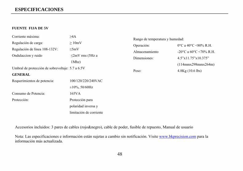
ESPECIFICACIONES Accesorios incluidos: 3 pares de cables (rojo&negro), cable de poder, fusible de repuesto, Manual de usuario Nota: Las especificaciones e información están sujetas a cambio sin notificación. Visite www.bkprecision.com para la información más actualizada.
FUENTE FIJA DE 5V
Corriente máxima: ≥4A
Regulación de carga: ≥ 10mV
Regulación de línea 108-132V: ≤5mV
Ondulaccion y ruido ≤2mV rms (5Hz a
1Mhz)
Umbral de protección de sobrevoltaje: 5.7 a 6.5V
GENERAL
Requerimientos de potencia: 100/120/220/240VAC
±10%, 50/60Hz
Consumo de Potencia: 165VA
Protección: Protección para
polaridad inversa y
limitación de corriente
Rango de temperatura y humedad:
Operación: 0°C a 40°C <80% R.H.
Almacenamiento -20°C a 60°C <70% R.H.
Dimensiones: 4.5”x11.75”x10.375”
(114mmx298mmx264m)
Peso: 4.8Kg (10.6 lbs)
49
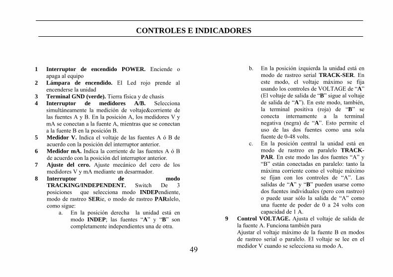
CONTROLES E INDICADORES
1 Interruptor de encendido POWER. Enciende o apaga al equipo 2 Lámpara de encendido. El Led rojo prende al encenderse la unidad 3 Terminal GND (verde). Tierra física y de chasis 4 Interruptor de medidores A/B. Selecciona
simultáneamente la medición de voltaje&corriente de las fuentes A y B. En la posición A, los medidores V y mA se conectan a la fuente A, mientras que se conectan a la fuente B en la posición B.
5 Medidor V. Indica el voltaje de las fuentes A ó B de acuerdo con la posición del interruptor anterior.
6 Medidor mA. Indica la corriente de las fuentes A ó B de acuerdo con la posición del interruptor anterior.
7 Ajuste del cero. Ajuste mecánico del cero de los medidores V y mA mediante un desarmador.
8 Interruptor de modo TRACKING/INDEPENDENT. Switch De 3 posiciones que selecciona modo INDEPendiente, modo de rastreo SERie, o modo de rastreo PARalelo, como sigue:
a. En la posición derecha la unidad está en modo INDEP; las fuentes “A” y “B” son completamente independientes una de otra.
b. En la posición izquierda la unidad está en modo de rastreo serial TRACK-SER. En este modo, el voltaje máximo se fija usando los controles de VOLTAGE de “A” (El voltaje de salida de “B” sigue al voltaje de salida de “A”). En este modo, también, la terminal positiva (roja) de “B” se conecta internamente a la terminal negativa (negra) de “A”. Esto permite el uso de las dos fuentes como una sola fuente de 0-48 volts.
c. En la posición central la unidad está en modo de rastreo en paralelo TRACK-PAR. En este modo las dos fuentes “A” y “B” están conectadas en paralelo: tanto la máxima corriente como el voltaje máximo se fijan con los controles de “A”. Las salidas de “A” y “B” pueden usarse como dos fuentes individuales (pero con rastreo) o puede usar sólo la salida de “A” como una fuente de poder de 0 a 24 volts con capacidad de 1 A.
9 Control VOLTAGE. Ajusta el voltaje de salida de la fuente A. Funciona también para Ajustar el voltaje máximo de la fuente B en modos de rastreo serial o paralelo. El voltaje se lee en el medidor V cuando se selecciona su modo A.

50
Figura 1. Controles e indicadores del panel frontal
51
CONTROLES E INDICADORES
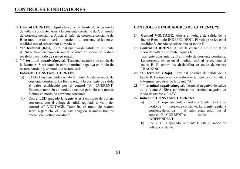
CONTROLES E INDICADORES DE LA FUENTE “B” 14 Control VOLTAGE. Ajusta el voltaje de salida de la
fuente B en modo INDEPENDENT. El voltaje se lee en el medidor V cuando se selecciona su modo B.
19. Control CURRENT. Ajusta la corriente límite de B en modo de voltaje constante. Ajusta la
corriente constante de B en modo de corriente constante. La corriente se lee en el medidor mA al seleccionar el modo B. El control se deshabilita en modo de rastreo TRACKING.
20. “+” terminal (Roja). Terminal positiva de salida de la fuente B. En operación de rastreo serial, queda conectada a la terminal negativa de la fuente “A”
21. “-“ terminal negativa(negra). Terminal negativa de salida de la fuente A. Sirve también como terminal negativa en modo de rastreo e 0-48V.
22. Indicador CONSTANT CURRENT. a) El LED rojo enciende cuando la fuente B está en
modo de corriente constante. La fuente regula la corriente de salida al valor establecido por el control “B” CURRENT en modo INDEPENDENT.
b) Con el LED apagado la fuente B está en modo de voltaje constante.
10. Control CURRENT. Ajusta la corriente límite de A en modo de voltaje constante. Ajusta la corriente constante de A en modo de corriente constante. Ajusta el valor de corriente constante de B en modo de rastro serial o paralelo. La corriente se lee en el medidor mA al seleccionar el modo A.
11. “+” terminal (Roja). Terminal positiva de salida de la fuente A. Sirve también como terminal positiva en modo de rastreo paralelo y en modo de rastreo serial.
12. “-“ terminal negativa(negra). Terminal negativa de salida de la fuente A. Sirve también como terminal negativa en modo de rastreo paralelo y en modo de rastreo serial.
13. Indicador CONSTANT CURRENT. a) El LED rojo enciende cuando la fuente A está en modo de
corriente constante. La fuente regula la corriente de salida al valor establecido por el control “A” CURRENT. Enciende también en modo de rastreo paralelo con ambas fuentes en modo de corriente constante.
b) Con el LED apagado la fuente A está en modo de voltaje constante, con el voltaje de salida regulado al valor del control A” VOLTAGE. También, en modo de rastreo serial o paralelo, el LED está apagado si ambas fuentes operan con voltaje constante.
52
CONTROLES E INDICADORES
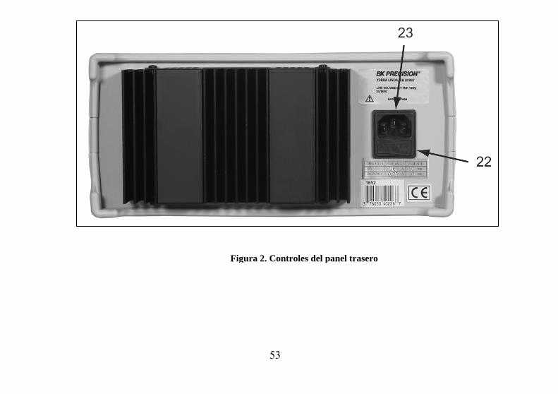
INDICADORES Y CONTROLES DE LA FUENTE DE 5V
25. Terminal “+“ (roja). Terminal de polaridad positiva de la fuente FIXED de 5V.
26. Terminal “-“ (negra). Terminal de polaridad negativa de la fuente FIXED de 5V.
27. Indicador de sobreflujo OVERLOAD de 5A. Enciende cuando la carga de la fuente es excesiva.
CONTROLES DEL PANEL TRASERO 23. Switches LINE VOLTAGE SELECT. Para
establecer operación universal de potencia mediante combinaciones.
24. Receptáculo del cable de poder. Fusible.
53
Figura 2. Controles del panel trasero
54
INSTRUCCIONES DE OPERACIÓN
PRECAUCIONES PARA SEGURIDAD
PRECAUCION Evite tocar el disipador de calor en la parte trasera de la fuente de poder. Cuando la fuente provee una corriente alta en cualquiera de sus salidas el disipador puede estar muy caliente. El tocarlo en estas condiciones puede ocasionar quemadas de la piel o daños al equipo que esté en contacto con el disipador. Use sólo un enchufe de ac polarizado de 3 puntas. Esto asegura que el chasis de la fuente esté conectado a una buena tierra física y se reduce el peligro de un choque eléctrico.Existe un gran peligro si la salida se conecta a un voltaje externo alto. Algunos equipos que se conectan a la fuente pueden contener voltajes altos y presentan un riesgo de choque eléctrico.Si la salida de la fuente de poder es “flotante” (con referencia a un voltaje en vez de a tierra) apague la fuente y el equipo bajo prueba al efectuar conexiones. Nunca flote la fuente a un potencial mayor de 100 volts pico respecto a tierra física.
PRECAUCIONES PARA EL EQUIPO Evite usar la fuente de poder a temperaturas mayores de +40°C. Prevea suficiente espacio para el flujo de aire alrededor del disipador de calor en la parte trasera del aparato para una buena radiación que evite el aumento de calor interno. Aunque la fuente de poder está protegida contra daños por polaridad inversa, el circuito al que se conecta puede no incluir tal No exceda del voltaje máximo del circuito al que se conecta. Muchos transistores y circuitos integrados no soportan voltajes superiores a 30V. No debe preocuparse por daños al circuito bajo prueba por picos de voltaje o sobreflujo. El voltaje de salida de la fuente nunca excede del preestablecido cuando la fuente se enciende o apaga mediante el interruptor POWER. USO INDEPENDIENTE DE LA FUENTE “A” O “B” Cada una de las fuentes “A” y “B” proveen salida de 0–24 volts y hasta 0.5 amps. En el procedimiento que sigue se cubre el uso de las fuentes cuando se usan independientemente una de otra. En el modo de operación INDEP, los controles operativos de las dos fuentes son totalmente independientes y cada fuente puede usarse individualmente, o bien ambas en forma simultánea. Cubrimos aquí la operación básica; algunas variaciones se tratan en la sección de APLICACIONES de este manual.
55
INSTRUCCIONES DE OPERACIÓN
Alambre
Conexiones
1. Ajuste el interruptor INDEP/TRACK a su posición de la derecha para que la fuente opere en modo INDEP.
2. Seleccione la posición superior del interruptor A/B de los medidores para monitorear a la fuente A.
3. Apague la fuente de poder y el circuito bajo prueba durante el proceso de conexión
4. Conecte la terminal positiva del equipo bajo prueba a la terminal roja (+) de la fuente
5. Conecte la terminal negativa del equipo bajo prueba a la terminal negra (-) de la fuente
6. En la Fig. 3 se ilustran las posibilidades de conexión a tierra en el modo INDEP
c. Si la polaridad negativa del circuito bajo prueba es también el chasis o común, puede conectarse a tierra uniendo la terminal (-) negra con la verde (GND) como se muestra en la Fig. 3A
d. Similarmente, la polaridad positiva puede aterrizarse uniendo la terminal roja (+) a la verde (GND) como en la Fig. 3B.
e. Si no se requiere referencia de tierra, puede usar la configuración de la Fig. 3C. Esta puede usarse también si desconoce si el chasis es común con polaridad positiva o negativa.
f. Si el chasis o común del circuito bajo prueba está separado de las entradas de polaridad positiva y de la negativa, use las conexiones de la Fig. 3D.
7. Tenga cuidado con la polaridad. Si el equipo por probarse no incluye protección contra polaridad inversa, dicho equipo puede dañarse con polaridad inversa. Use puntas con colores para identificar la polaridad, rojo para (+), negro para (-). 8. Asegúrese que los cables de conexión permiten la
corriente suficiente y poseen resistencia baja entre Operación típica de voltaje constante 1. Antes de conectar el dispositivo por activar a la
fuente, determine la máxima corriente de carga que soporta con seguridad el dispositivo, y establezca dicho valor como valor límite de corriente (vea “Estableciendo la corriente límite” en esta sección).
2. Fije el interruptor de los medidores a la posición superior para monitorear la fuente A
3. Fije el valor del control VOLTAGE a su mínimo (contra las manecillas del reloj)
4. Apague el aparato y conéctelo al circuito por probar (vea instrucciones previas)
5. Encienda la unidad mediante el switch POWER. El LED CONSTANT CURRENT no debe encenderse.
6. Incremente el voltaje mediante VOLTAGE hasta el valor deseado que aparece en el medidor
7. La corriente puede leerse en el medidor mA
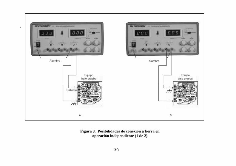
56
.
Figura 3. Posibilidades de conexión a tierra en operación independiente (1 de 2)
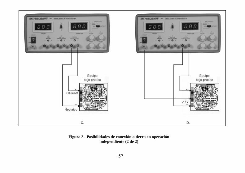
57
Figura 3. Posibilidades de conexión a tierra en operación independiente (2 de 2)
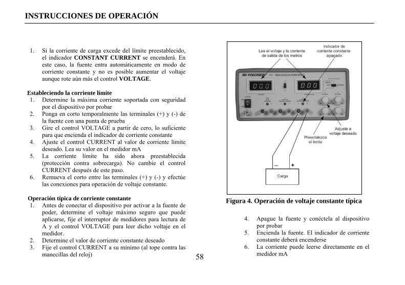
58
INSTRUCCIONES DE OPERACIÓN
Figura 4. Operación de voltaje constante típica
1. Si la corriente de carga excede del límite preestablecido, el indicador CONSTANT CURRENT se encenderá. En este caso, la fuente entra automáticamente en modo de corriente constante y no es posible aumentar el voltaje aunque rote aún más el control VOLTAGE.
Estableciendo la corriente límite 1. Determine la máxima corriente soportada con seguridad
por el dispositivo por probar 2. Ponga en corto temporalmente las terminales (+) y (-) de
la fuente con una punta de prueba 3. Gire el control VOLTAGE a partir de cero, lo suficiente
para que encienda el indicador de corriente constante 4. Ajuste el control CURRENT al valor de corriente límite
deseado. Lea su valor en el medidor mA 5. La corriente límite ha sido ahora preestablecida
(protección contra sobrecarga). No cambie el control CURRENT después de este paso.
6. Remueva el corto entre las terminales (+) y (-) y efectúe las conexiones para operación de voltaje constante.
Operación típica de corriente constante 1. Antes de conectar el dispositivo por activar a la fuente de
poder, determine el voltaje máximo seguro que puede aplicarse, fije el interruptor de medidores para lectura de A y el control VOLTAGE para leer dicho voltaje en el medidor.
2. Determine el valor de corriente constante deseado 3. Fije el control CURRENT a su mínimo (al tope contra las
manecillas del reloj)
4. Apague la fuente y conéctela al dispositivo por probar
5. Encienda la fuente. El indicador de corriente constante deberá encenderse
6. La corriente puede leerse directamente en el medidor mA
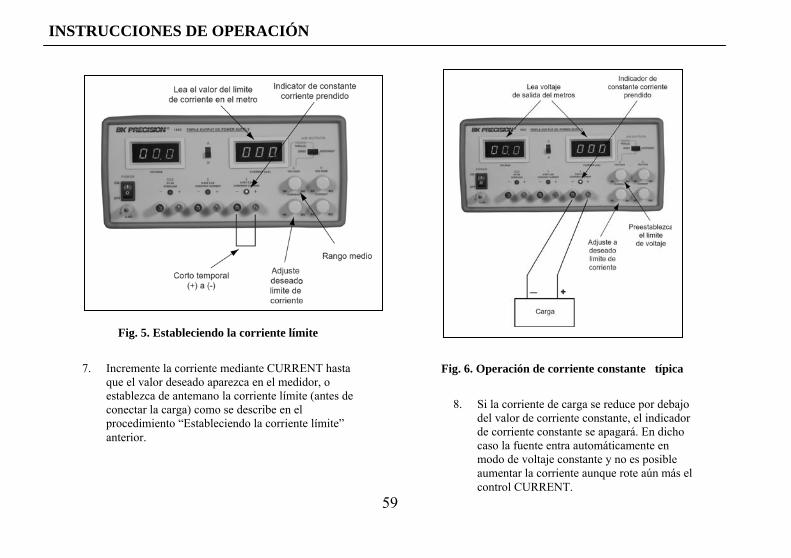
59
INSTRUCCIONES DE OPERACIÓN
Fig. 5. Estableciendo la corriente límite
Fig. 6. Operación de corriente constante típica7. Incremente la corriente mediante CURRENT hasta que el valor deseado aparezca en el medidor, o establezca de antemano la corriente límite (antes de conectar la carga) como se describe en el procedimiento “Estableciendo la corriente límite” anterior.
8. Si la corriente de carga se reduce por debajo del valor de corriente constante, el indicador de corriente constante se apagará. En dicho caso la fuente entra automáticamente en modo de voltaje constante y no es posible aumentar la corriente aunque rote aún más el control CURRENT.

60
INSTRUCCIONES DE OPERACIÓN
Figura 7. Característica de voltaje/corriente constante
Característica de voltaje constante/corriente constante La característica de trabajo de la fuente es del tipo de cruce automático de voltaje/corriente. Esto permite la transición continua de los modos de corriente constante a voltaje constante en respuesta a cambios de la carga. La intersección de los modos de corriente y voltaje constantes se llama el punto de cruce. La Fig. 3 muestra la relación entre dicho punto de cruce y la carga. Por ejemplo, si la carga es tal que la fuente está operando en el modo de voltaje constante, se dispone de una salida de voltaje regulada. El voltaje permanece constante conforme se aumenta la carga, hasta el punto en el cual se alcanza el límite de corriente preestablecido. En ese punto, la corriente de salida se vuelve constante y el voltaje de salida disminuye en proporción al aumento de la carga. El punto de cruce se indica por los LEDS frontales. El punto de cruce se alcanza cuando enciende el indicador de corriente constante. Similarmente, el cruce del modo de corriente constante a voltaje constante ocurre automáticamente al disminuir la carga. Un buen ejemplo ocurre al cargar una batería de automóvil de 12 volts. Inicialmente, el voltaje sin carga de la fuente puede establecerse en 13.8 volts. Una batería baja representa una carga pesada para la fuente, y operará en modo de corriente constante, que puede ajustarse a una razón de carga de 2 amps. Conforme la batería se carga, y su voltaje se acerca a 13.8 volts, su carga se reduce de manera tal que ya no demanda los 0.5 amps. Este es el punto de cruce en el cual la fuente de poder entra en modo de voltaje constante.
OPERACIÓN DE RASTREO EN SERIE Cuando se selecciona el modo de operación de rastreo en serie, la terminal positiva (roja) de la fuente”B” se conecta internamente a la terminal negativa (negra) de la fuente “A”. Esto permite el uso del aparato como una sola fuente de 0 a 48 volts usando simplemente las terminales negativa (negra) de “B” y la positiva (roja) de “A”.
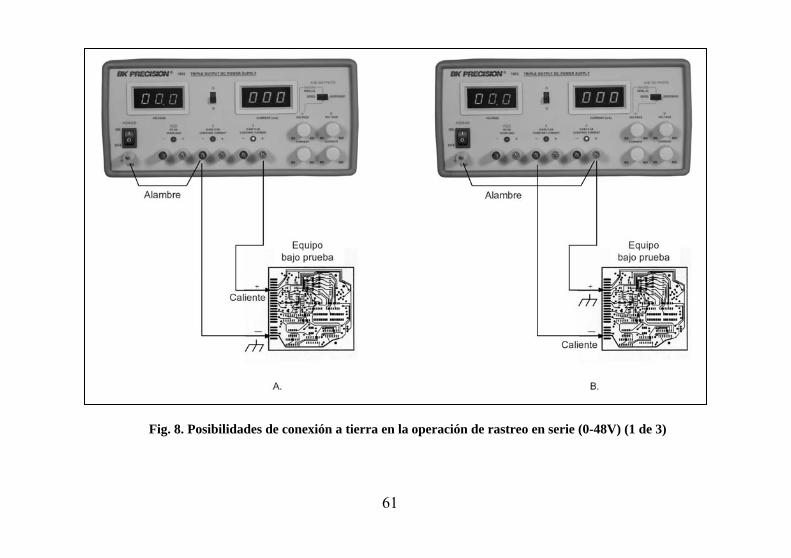
61
Fig. 8. Posibilidades de conexión a tierra en la operación de rastreo en serie (0-48V) (1 de 3)
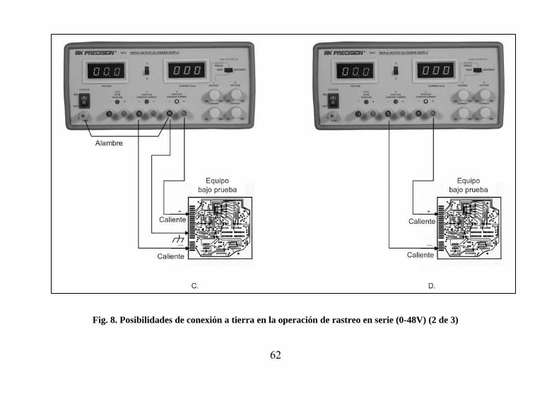
62
Fig. 8. Posibilidades de conexión a tierra en la operación de rastreo en serie (0-48V) (2 de 3)
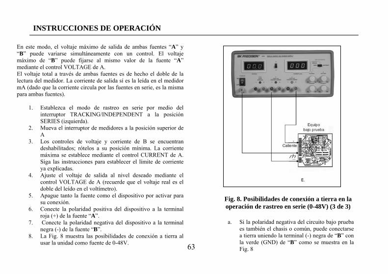
63
INSTRUCCIONES DE OPERACIÓN
En este modo, el voltaje máximo de salida de ambas fuentes “A” y “B” puede variarse simultáneamente con un control. El voltaje máximo de “B” puede fijarse al mismo valor de la fuente “A” mediante el control VOLTAGE de A. El voltaje total a través de ambas fuentes es de hecho el doble de la lectura del medidor. La corriente de salida sí es la leída en el medidor mA (dado que la corriente circula por las fuentes en serie, es la misma para ambas fuentes).
1. Establezca el modo de rastreo en serie por medio del interruptor TRACKING/INDEPENDENT a la posición SERIES (izquierda).
2. Mueva el interruptor de medidores a la posición superior de A
3. Los controles de voltaje y corriente de B se encuentran deshabilitados; rótelos a su posición mínima. La corriente máxima se establece mediante el control CURRENT de A. Siga las instrucciones para establecer el límite de corriente ya explicadas.
4. Ajuste el voltaje de salida al nivel deseado mediante el control VOLTAGE de A (recuerde que el voltaje real es el doble del leído en el voltímetro).
5. Apague tanto la fuente como el dispositivo por activar para su conexión.
6. Conecte la polaridad positiva del dispositivo a la terminal roja (+) de la fuente “A”.
7. Conecte la polaridad negativa del dispositivo a la terminal negra (-) de la fuente “B”.
8. La Fig. 8 muestra las posibilidades de conexión a tierra al usar la unidad como fuente de 0-48V.
a. Si la polaridad negativa del circuito bajo prueba es también el chasis o común, puede conectarse a tierra uniendo la terminal (-) negra de “B” con la verde (GND) de “B” como se muestra en la Fig. 8
Fig. 8. Posibilidades de conexión a tierra en la operación de rastreo en serie (0-48V) (3 de 3)
64
INSTRUCCIONES DE OPERACIÓN
.Sólo las terminales de la fuente “A” se usan en el modo de rastreo en paralelo. El voltaje y corriente de salida de la fuente “B” rastrean (siguen) a las salidas de voltaje y corriente de la fuente “A”. 1. Establezca el modo de rastreo en paralelo de las fuentes
“A” y “B” fijando el interruptor TRACKING/INDEPENDENT a su posición media.
2. Fije el interruptor de los medidores a su posición superior A. El voltaje es como se lee en el medidor. La corriente será exactamente el DOBLE del valor leído en el medidor mA (dado que cada fuente suministra el mismo valor de corriente).
3. Los controles VOLTAGE y CURRENT de B están deshabilitados; gírelos a sus posiciones mínimas. La corriente y el voltaje máximo se fijan con los controles A. Usando las terminales de salida de la fuente A, establezca la corriente límite de acuerdo con las instrucciones anteriores de esta sección. Recuerde que la corriente de salida de A es realmente el doble del valor leído en el medidor.
4. Ajuste el voltaje de salida al nivel deseado usando el control “A”VOLTAGE.
5. Apague tanto la fuente como el circuito por activar para su conexión
6. Conecte la polaridad positiva del dispositivo por activar a la terminal roja (+) de la fuente “A”.
7. Conecte la polaridad negativa del dispositivo por activar a la terminal negra (-) de la fuente “A”.
8. La Fig. 9 ilustra las posibilidades de conexión a tierra del modo TRACKING PARALLEL
b. Similarmente, la polaridad positiva puede aterrizarse uniendo la terminal roja (+) de “A” a la verde (GND) de “A” como en la Fig. 8B.
c. Si desea una operación de “fuentes separadas” puede lograr un voltaje positivo y uno negativo con tierra central uniendo las terminales negra (-) y verde (GND) de la fuente “A” como se muestra en la Fig. 8C. Consulte la sección de APLICACIONES en este manual para más información sobre la operación de “fuentes separadas”.
d. Si no se requiere referencia de tierra, puede usar la configuración de la Fig. 8D. Esta puede usarse también si desconoce si el chasis es común con polaridad positiva o negativa.
e. Si el chasis o común del circuito bajo prueba está separado de las entradas de polaridad positiva y de la negativa, use las conexiones de la Fig. 8E
9. Tenga cuidado con la polaridad. Si el equipo por probarse no incluye protección contra polaridad inversa, ducho equipo puede dañarse con polaridad inversa. Use puntas con colores para identificar la polaridad, rojo para (+), negro para (-).
10. Asegúrese que los cables de conexión permiten la corriente suficiente y poseen resistencia baja entre la fuente y el circuito por probar. Las puntas suministradas soportan 4 A
OPERACIÓN DE RASTREO EN PARALELO En este modo de operación las dos fuentes están unidas en paralelo. Esto permite una fuente de 0-24V con capacidad de corriente de 1 A.

65
Fig. 9. Posibilidades de conexión a tierra en operación de rastreo en paralelo (1 de 2)
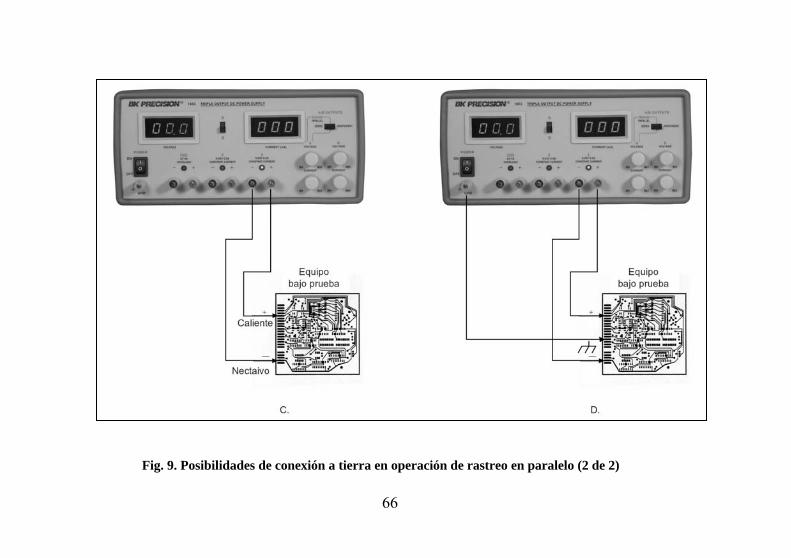
66
Fig. 9. Posibilidades de conexión a tierra en operación de rastreo en paralelo (2 de 2)
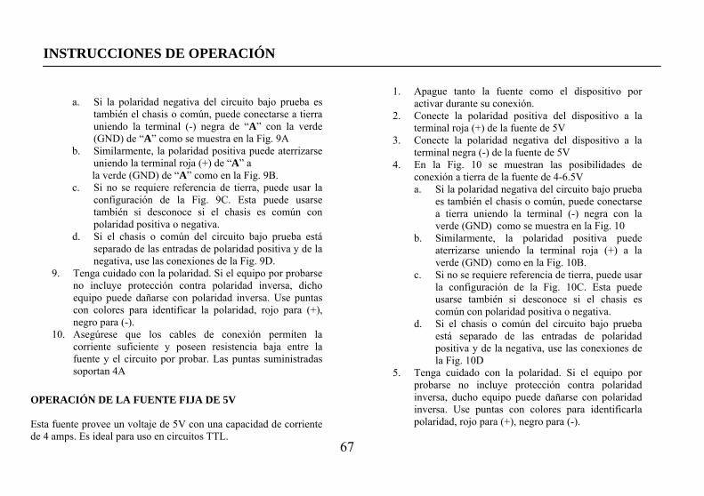
67
INSTRUCCIONES DE OPERACIÓN
a. Si la polaridad negativa del circuito bajo prueba es también el chasis o común, puede conectarse a tierra uniendo la terminal (-) negra de “A” con la verde (GND) de “A” como se muestra en la Fig. 9A
b. Similarmente, la polaridad positiva puede aterrizarse uniendo la terminal roja (+) de “A” a la verde (GND) de “A” como en la Fig. 9B.
c. Si no se requiere referencia de tierra, puede usar la configuración de la Fig. 9C. Esta puede usarse también si desconoce si el chasis es común con polaridad positiva o negativa.
d. Si el chasis o común del circuito bajo prueba está separado de las entradas de polaridad positiva y de la negativa, use las conexiones de la Fig. 9D.
9. Tenga cuidado con la polaridad. Si el equipo por probarse no incluye protección contra polaridad inversa, dicho equipo puede dañarse con polaridad inversa. Use puntas con colores para identificar la polaridad, rojo para (+), negro para (-).
10. Asegúrese que los cables de conexión permiten la corriente suficiente y poseen resistencia baja entre la fuente y el circuito por probar. Las puntas suministradas soportan 4A
OPERACIÓN DE LA FUENTE FIJA DE 5V Esta fuente provee un voltaje de 5V con una capacidad de corriente de 4 amps. Es ideal para uso en circuitos TTL.
1. Apague tanto la fuente como el dispositivo por activar durante su conexión.
2. Conecte la polaridad positiva del dispositivo a la terminal roja (+) de la fuente de 5V
3. Conecte la polaridad negativa del dispositivo a la terminal negra (-) de la fuente de 5V
4. En la Fig. 10 se muestran las posibilidades de conexión a tierra de la fuente de 4-6.5V a. Si la polaridad negativa del circuito bajo prueba
es también el chasis o común, puede conectarse a tierra uniendo la terminal (-) negra con la verde (GND) como se muestra en la Fig. 10
b. Similarmente, la polaridad positiva puede aterrizarse uniendo la terminal roja (+) a la verde (GND) como en la Fig. 10B.
c. Si no se requiere referencia de tierra, puede usar la configuración de la Fig. 10C. Esta puede usarse también si desconoce si el chasis es común con polaridad positiva o negativa.
d. Si el chasis o común del circuito bajo prueba está separado de las entradas de polaridad positiva y de la negativa, use las conexiones de la Fig. 10D
5. Tenga cuidado con la polaridad. Si el equipo por probarse no incluye protección contra polaridad inversa, ducho equipo puede dañarse con polaridad inversa. Use puntas con colores para identificarla polaridad, rojo para (+), negro para (-).
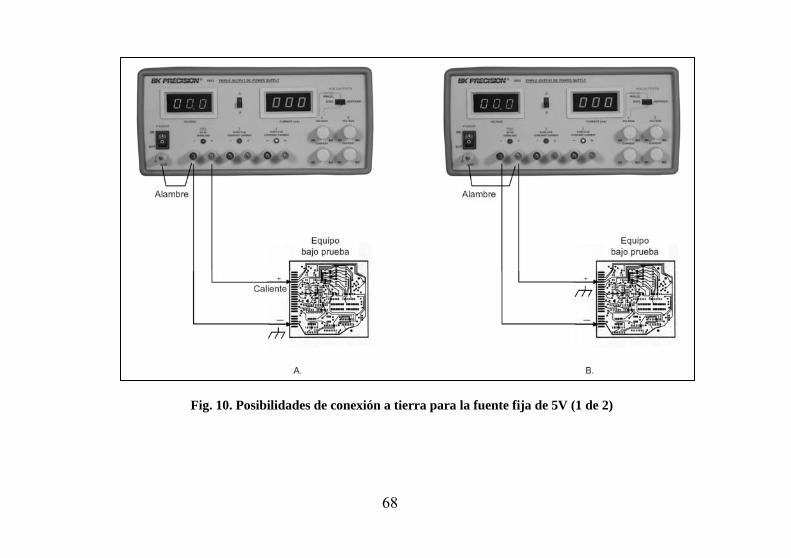
68
Fig. 10. Posibilidades de conexión a tierra para la fuente fija de 5V (1 de 2)
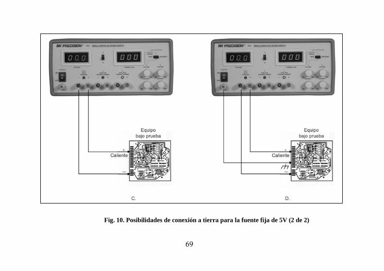
69
Fig. 10. Posibilidades de conexión a tierra para la fuente fija de 5V (2 de 2)
70
INSTRUCCIONES DE OPERACIÓN
6. Asegúrese que los cables de conexión permiten la corriente suficiente y poseen resistencia baja entre la fuente y el circuito por probar. Los cables suministrados soportan 4A.
7. Si enciende la luz roja indicadora de sobrecarga OVERLOAD significa que la carga es excesiva. Esto causa que bajen el voltaje y la corriente y evita que opere correctamente la fuente fija de 5V. Para corregir esta situación, reduzca la carga para que demande menos de 4A.
NOTA: Si al reducir la carga no se apaga el indicador de sobrecarga, es que se ha activado el circuito de protección. Para resumir la operación normal, reduzca el voltaje de salida y apague momentáneamente el aparato.
71
APLICACIONES
GENERAL La fuente de poder modelo 1651A tiene una gran variedad de aplicaciones en servicio eléctrico y electrónico, laboratorios de ingeniería, instalaciones de manufactura y pruebas, escuelas y el hogar. Las salidas de las fuentes “A” y “B” son totalmente ajustables de 0 a 24 volts y 0 a 0.5 amps y la fuente de 5V ofrece una corriente de 0 a 5 amps. Esta flexibilidad le permite el uso en la mayoría de las aplicaciones que requieren de una fuente de dc. SERVICIO ELECTRÓNICO La mayoría de los diagnósticos y reparaciones electrónicas se ejecutan en un banco de pruebas. Esta fuente puede proveer la potencia para operar un módulo o tablilla de circuito impreso separado de su equipo original. Puede usarse en equipos portátiles accionados por baterías y verificar el efecto de una batería baja. Puede activar equipo automotor como reproductores de cinta, sistemas de audio, radios CB, etc. en el banco de pruebas. El modo de rastreo en paralelo soporta hasta 1 amp La mayoría de los automóviles y otros vehículos usan sistemas eléctricos de 12 volts. Aunque la batería se especifica a 12 volts, su voltaje a plena carga es de 13.8 volts aproximadamente. La fuente de poder puede ajustarse a 13.8 volts para el servicio de equipos automotores con baterías de 12 volts. Algunos camiones utilizan sistemas eléctricos de 24 volts; las pruebas de sus equipos deben realizarse a 28 volts.
Algunas aplicaciones requieren de la inyección de un voltaje variable dc para ciertas pruebas, como la verificación de la polarización AGC en un receptor de TV. Esto requiere una fuente aislada, como el modelo 1651A. El equipo bajo prueba puede contener su propia fuente de poder a partir de la línea de ac; un voltaje de dc puede ya estar presente en el circuito. Una polaridad de la salida de la fuente se “flota” a un punto apropiado del circuito, como el emisor de un transistor. La otra polaridad se aplica a otro punto, como la base de dicho transistor. Al variar el voltaje de la fuente de poder se cambia la polarización dc del paso, y se anotan los cambios. Usualmente se usa un resistor en serie para proteger los circuitos contra una disipación excesiva. MANUFACTURA ELECTRÓNICA La fuente de poder de dc se usa frecuentemente en los procesos de manufactura y de control de calidad al probar y ajustar módulos, subensambles y unidades completas. El instrumento se usa asimismo como fuente de poder de dc al probar insumos de producción como subensambles y componentes. Esta fuente se recomienda particularmente para aplicaciones de manufactura debido a su facilidad de operación y capacidad de operar continuamente. Cuando las características más importantes por medir son corriente y consumo de potencia, la corriente y el voltaje se exhiben fácilmente en pantalla. Al fijar la corriente límite se determinan con facilidad las unidades que no cumplen las especificaciones de corriente de carga observando el indicador de CONSTANT CURRENT, para su rechazo.
72
APLICACIONES
LABORATORIO DE DISEÑO ELECTRÓNICO El técnico o ingeniero que labora en un laboratorio de ingeniería requiere de una fuente de dc para activar circuitos prototipo. Esta fuente es ideal ya que monitorea el voltaje y la corriente, limita la corriente para proteger al circuito, es ajustable en un rango amplio y posee excelente regulación y bajo ondulaccion. El uso de la fuente en un laboratorio es similar al descrito para el servicio, excepto que, al probar circuitos individuales se manejan corrientes más bajas que en circuitos completos. La característica de limitación de corriente es muy útil puesto que protege a circuitos no probados contra daños. EDUCACIÓN EN ELECTRÓNICA El estudiante de electrónica puede usar la fuente para activar circuitos y equipos como se ha descrito previamente. Además, la fuente puede usarse en laboratorios de enseñanza para realizar experimentos sobre fundamentos de electricidad y electrónica. Al estudiar la Ley de Ohm, por ejemplo, la relación entre resistencia, voltaje y corriente se demuestra fácilmente usando una fuente de poder de dc. CARGA DE BATERIAS La fuente de poder puede usarse como cargador de baterías del tipo de plomo-ácido, níquel-cadmio y algunas alcalinas. Refiérase a las especificaciones de carga de los fabricantes para los valores requeridos de voltaje y corriente.
La información sobre carga se imprime en ocasiones en las propias baterías. La carga de baterías requiere, al menos al inicio., de operación en modo de corriente constante. Antes de conectar la fuente a la batería, fije los controles VOLTAGE al voltaje de plena carga especificado por el fabricante;apague la fuente durante la conexión. Verifique la polaridad correcta y conecte en modo de corriente constante. Ajuste el control CURRENT al valor máximo de carga especificado (Si ese valor es mayor que el que entrega la fuente, establezca el control al máximo de la fuente). El indicador se encenderá y la batería se cargará con la corriente límite establecida. Conforme la batería se carga, su voltaje se acerca al de salida de la fuente y la corriente de carga disminuye. La fuente puede entonces cambiar automáticamente al modo de voltaje constante C, proveyendo una tenue carga. FUENTE DIVIDIDA Con cierta frecuencia se requieren “fuentes de poder divididas” para amplificadores y otros circuitos electrónicos. El modelo 1651A es ideal para la operación de “fuente dividida”, con dos voltajes positivos y un negativo común, dos voltajes negativos y un positivo común, o bien uno negativo, uno positivo y una tierra común. Además, cada una de estas configuraciones puede obtenerse con voltajes iguales o diferentes.
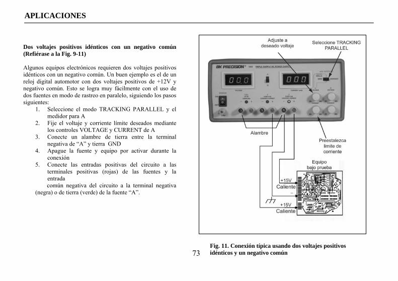
73
APLICACIONES
Dos voltajes positivos idénticos con un negativo común (Refiérase a la Fig. 9-11) Algunos equipos electrónicos requieren dos voltajes positivos idénticos con un negativo común. Un buen ejemplo es el de un reloj digital automotor con dos voltajes positivos de +12V y negativo común. Esto se logra muy fácilmente con el uso de dos fuentes en modo de rastreo en paralelo, siguiendo los pasos siguientes:
1. Seleccione el modo TRACKING PARALLEL y el medidor para A
2. Fije el voltaje y corriente límite deseados mediante los controles VOLTAGE y CURRENT de A
3. Conecte un alambre de tierra entre la terminal negativa de “A” y tierra GND
4. Apague la fuente y equipo por activar durante la conexión
5. Conecte las entradas positivas del circuito a las terminales positivas (rojas) de las fuentes y la entrada común negativa del circuito a la terminal negativa
(negra) o de tierra (verde) de la fuente “A”.
Fig. 11. Conexión típica usando dos voltajes positivos idénticos y un negativo común
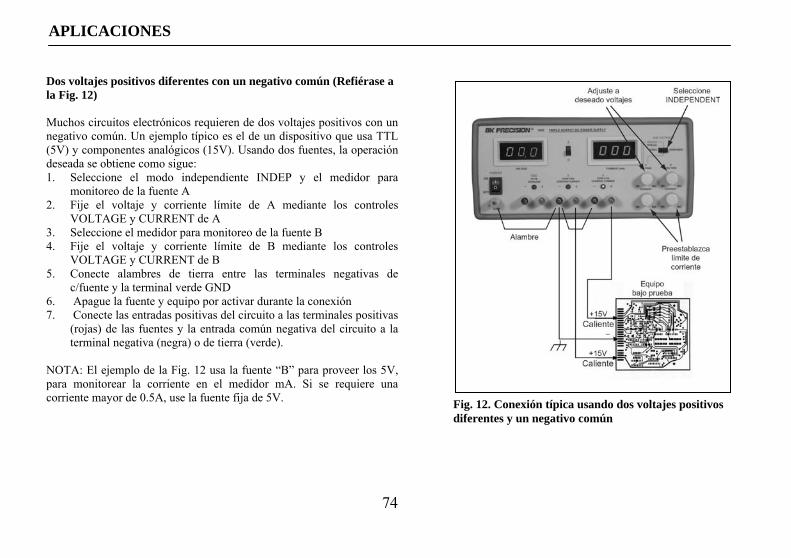
74
APLICACIONES
Dos voltajes positivos diferentes con un negativo común (Refiérase a la Fig. 12) Muchos circuitos electrónicos requieren de dos voltajes positivos con un negativo común. Un ejemplo típico es el de un dispositivo que usa TTL (5V) y componentes analógicos (15V). Usando dos fuentes, la operación deseada se obtiene como sigue: 1. Seleccione el modo independiente INDEP y el medidor para
monitoreo de la fuente A 2. Fije el voltaje y corriente límite de A mediante los controles
VOLTAGE y CURRENT de A 3. Seleccione el medidor para monitoreo de la fuente B 4. Fije el voltaje y corriente límite de B mediante los controles
VOLTAGE y CURRENT de B 5. Conecte alambres de tierra entre las terminales negativas de
c/fuente y la terminal verde GND 6. Apague la fuente y equipo por activar durante la conexión 7. Conecte las entradas positivas del circuito a las terminales positivas
(rojas) de las fuentes y la entrada común negativa del circuito a la terminal negativa (negra) o de tierra (verde).
NOTA: El ejemplo de la Fig. 12 usa la fuente “B” para proveer los 5V, para monitorear la corriente en el medidor mA. Si se requiere una corriente mayor de 0.5A, use la fuente fija de 5V.
Fig. 12. Conexión típica usando dos voltajes positivos diferentes y un negativo común
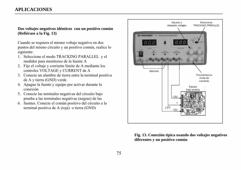
75
APLICACIONES
Fig. 13. Conexión típica usando dos voltajes negativos diferentes y un positivo común
Dos voltajes negativos idénticos con un positivo común (Refiérase a la Fig. 13) Cuando se requiera el mismo voltaje negativo en dos puntos del mismo circuito y un positivo común, realice lo siguiente: 1. Seleccione el modo TRACKING PARALLEL y el
medidor para monitoreo de la fuente A 2. Fije el voltaje y corriente límite de A mediante los
controles VOLTAGE y CURRENT de A 3. Conecte un alambre de tierra entre la terminal positiva
de A y tierra (GND) verde 4. Apague la fuente y equipo por activar durante la
conexión 5. Conecte las teminales negativas del circuito bajo
prueba a las terminales negativas (negras) de las 6. fuentes. Conecte el común positivo del circuito a la
terminal positiva de A (roja) o tierra (GND)
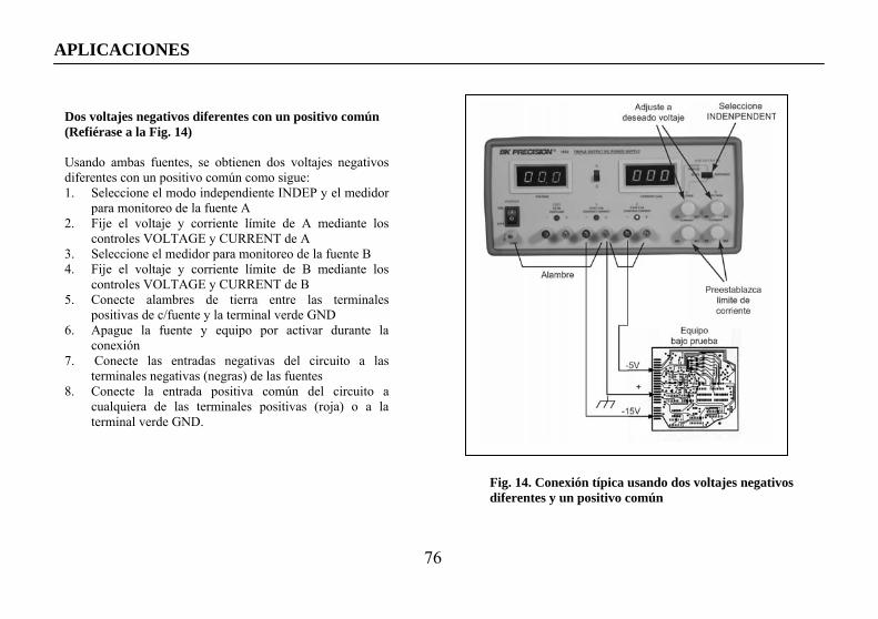
76
APLICACIONES
Dos voltajes negativos diferentes con un positivo común (Refiérase a la Fig. 14) Usando ambas fuentes, se obtienen dos voltajes negativos diferentes con un positivo común como sigue: 1. Seleccione el modo independiente INDEP y el medidor
para monitoreo de la fuente A 2. Fije el voltaje y corriente límite de A mediante los
controles VOLTAGE y CURRENT de A 3. Seleccione el medidor para monitoreo de la fuente B 4. Fije el voltaje y corriente límite de B mediante los
controles VOLTAGE y CURRENT de B 5. Conecte alambres de tierra entre las terminales
positivas de c/fuente y la terminal verde GND 6. Apague la fuente y equipo por activar durante la
conexión 7. Conecte las entradas negativas del circuito a las
terminales negativas (negras) de las fuentes 8. Conecte la entrada positiva común del circuito a
cualquiera de las terminales positivas (roja) o a la terminal verde GND.
Fig. 14. Conexión típica usando dos voltajes negativos diferentes y un positivo común
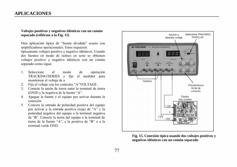
77
APLICACIONES
Voltajes positivos y negativos idénticos con un común separado (refiérase a la Fig. 15) Otra aplicación típica de “fuente dividida” ocurre con amplificadores operacionales. Estos requieren típicamente voltajes positivo y negativo idénticos. Usando dos fuentes en modo de rastreo en serie se obtienen voltajes positivo y negativo idénticos con un común separado como sigue: 1. Seleccione el modo de operación
TRACKING/SERIES y fije el medidor para monitorear el voltaje de a
2. Fije el voltaje con los controles “A”VOLTAGE . 3. Conecte la unión de tierra entre la terminal de tierra
(GND) y la negativa de la fuente “A”. 4. Apague la fuente y el equipo por activar durante la
conexión 5. Conecte la entrada de polaridad positiva del equipo
por activar a la entrada positiva (roja) de “A” y la polaridad negativa del equipo a la terminal negativa de “B”. Conecte la tierra del equipo a la terminal de tierra de la fuente “A”, a la positiva de “B” o a la terminal verde GND.
Fig. 15. Conexión típica usando dos voltajes positivos y negativos idénticos con un común separado
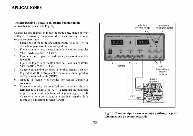
78
APLICACIONES
Voltajes positivo y negativo diferentes con un común separado (Refiérase a la Fig. 16) Usando las dos fuentes en modo independiente, puede obtener voltajes positivos y negativos diferentes con un común separado como sigue: 1. Seleccione el modo de operación INDEPENDENT y fije
el medidor para monitorear voltaje de A 2. Fije el voltaje y la corriente límite de A con los controles
VOLTAGE y CURRENT de A 3. Cambie el interruptor de medidores para monitorear a la
fuente B 4. Fije el voltaje y la corriente límite de B con los controles
VOLTAGE y CURRENT de B 5. Conecte un alambre de tierra la terminal negativa de A y
la positiva de B, y otro alambre entre la terminal positiva de B y la terminal verde (GND)
6. Apague la fuente y el circuito por activar durante la conexión
7. Conecte la terminal de polaridad positiva del circuito a la terminal roja positiva de A, y la terminal de polaridad negativa del circuito a la terminal negativa negra de B. 8. Conecte la tierra del circuito a la terminal negativa de la fuente A o a la terminal verde (GND)
Fig. 16. Conexión típica usando voltajes positivo y negativo diferentes con un común separado
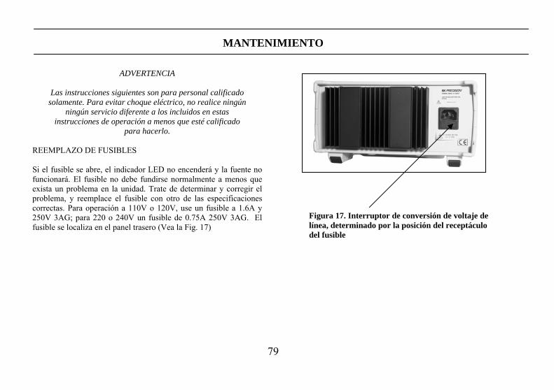
79
MANTENIMIENTO
ADVERTENCIA
Las instrucciones siguientes son para personal calificado solamente. Para evitar choque eléctrico, no realice ningún
ningún servicio diferente a los incluidos en estas instrucciones de operación a menos que esté calificado
para hacerlo. REEMPLAZO DE FUSIBLES Si el fusible se abre, el indicador LED no encenderá y la fuente no funcionará. El fusible no debe fundirse normalmente a menos que exista un problema en la unidad. Trate de determinar y corregir el problema, y reemplace el fusible con otro de las especificaciones correctas. Para operación a 110V o 120V, use un fusible a 1.6A y 250V 3AG; para 220 o 240V un fusible de 0.75A 250V 3AG. El fusible se localiza en el panel trasero (Vea la Fig. 17)
Figura 17. Interruptor de conversión de voltaje de línea, determinado por la posición del receptáculo del fusible
80
Información de Servicio
Servicio de Garantía: Por favor regrese el producto en el empaquetado original con prueba de la fecha de la compra a la dirección debajo. Indique claramente el problema en escritura, incluya todos los accesorios que se estan usado con el equipo. Servicio de No Garantía: Por favor regrese el producto en el empaquetado original con prueba de la fecha de la compra a la dirección debajo. Indique claramente el problema en escritura, incluya todos los accesorios que se estan usado con el equipo. Clientes que no tienen cuentas deben de incluir pago en forma de queque, orden de dinero, o numero de carta de crédito. Para los precisos mas corriente visite www.bkprecision.com y oprime “service/repair”. Vuelva toda la mercancía a B&K Precision Corp. con el envío pagado por adelantado. La carga global de la reparación para el servicio de la No-Garantía no incluye el envío de vuelta. El envío de vuelta a las localizaciones en norte americano es incluido para el servicio de la garantía. Para los envíos de noche y el envío del no-Norte los honorarios americanos satisfacen el contacto B&K Precision Corp. B&K Precision Corp. 22820 Savi Ranch Parkway Yorba Linda, CA 92887 www.bkprecision.com 714-921-9095 Incluya con el instrumento la dirección de vuelto para envío, nombre del contacto, número de teléfono y descripción del problema. Incluya con el instrumento su dirección de retorno completa, nombre de contacto, teléfono y la descripción del problema.

81
Garantía Limitada de Un Ano
B&K Precision Corp. Autorizaciones al comprador original que su productos y componentes serán libre de defectos por el periodo de un ano desde el día en que se compro. B&K Precision Corp. sin carga, repararemos o sustituir, a nuestra opción, producto defectivo o componentes. Producto devuelto tiene que ser acompañado con prueba de la fecha del la compra en la forma de un recibo de las ventas. Para obtener cobertura en los EE.UU., este producto debe ser registrado por medio de la forma de registro en www.bkprecision.com dentro de quince (15) días de la compra de este producto. Exclusiones: Esta garantía no se aplica en el evento de uso en error o abuso de este producto o el resultado de alteraciones desautorizado o reparaciones. La garantía es vacía si se altera, se desfigura o se quita el número de serie. B&K Precision Corp. no será obligado a dar servicio por danos consecuente, incluyendo sin limitaciones a danos resultando en perdida de uso. Algunos estados no permiten limitaciones de daños fortuitos o consecuentes. Tan la limitación o la exclusión antedicha puede no aplicarse a usted. Esta garantía le da ciertos derechos y pueden tener otros derechos, cuales cambian estado por estado. B&K Precision Corp. 22820 Savi Ranch Parkway Yorba Linda, CA 92887 www.bkprecision.com 714-921-9095
82
SEGURIDAD DE EL EQUIPO DE PRUEBA
(Continua por dentro de portada)
5. Párese sobre un material aislante en el piso, o tapete aislante, y coloque el equipo sobre una superficie aislante. Asegúrese que dichas superficies no estén húmedas o mojadas.
6. Use la probada técnica de “una mano en el bolsillo” al manejar una punta de prueba. Evite particularmente el tocar algún objeto
metálico cercano que pueda proveer una trayectoria a tierra.
7. Al probar un equipo con activado por voltaje de ac, recuerde que el voltaje de línea está presente usualmente en algunos circuitos de entrada de potencia como el interruptor de encendido, fusibles, transformador de poder, etc. cuando el equipo se conecte a un enchufe de ac, aún cuando el equipo esté apagado.
8. Algunos equipos con un enchufe de 2 puntas, e incluso otros con enchufes polarizados son del tipo de “chasis caliente”; entre estos
se incluyen receptores de TV y equipos de audio recientes. Un gabinete de madera o plástico aísla el chasis para proteger al usuario. Al remover el gabinete para servicio, existe un peligro serio de choque eléctrico si se toca el chasis. Además de este peligro, es posible dañar a los instrumentos de prueba o al equipo bajo prueba al conectar la punta de tierra del instrumento al “chasis caliente”. Para hacer mediciones en un equipo de “chasis caliente”, conecte siempre un transformador de aislamiento entre el enchufe de ac y el equipo bajo prueba. El transformador de aislamiento de B+K Precision modelo TR-110 o 1604, o la fuente de poder de AC modelo 1653 o 1655 son adecuados para la mayoría de las aplicaciones. Para mayor seguridad, trate a todo equipo con cable de ac de 2 puntas como del tipo de “chasis caliente” a menos que esté seguro que tienen un chasis aislado o conectado a tierra física.
9. Los productos de B+K Precision no están autorizados para uso que involucre el contacto directo entre nuestros productos y el
cuerpo humano, o como componentes críticos de un sistema de auxilio vital. Aquí “contacto directo” se refiere a cualquier conexión de o hacia nuestro equipo por medio de cables o medios de interrupción. Un “componente crítico” es cualquier componente de un sistema de soporte vital tal que, de fallar, sería razonable esperar que a su vez causara la falla del sistema, o que afectara su seguridad o desempeño efectivo.
10. Nunca trabaje sólo. Alguien debe estar cerca para ayudarle en caso necesario. Se recomienda entrenamiento en CPR (resucitación
cardio-pulmonar).

Declaration of CE Conformityaccording to EEC directives and NF EN 45014 norm
Responsible Party Alternate Manufacturing Site
Manufacturer’s Name: B&K Precision Corporation B&K Taiwan 0574
Manufacture’s Address: 22820 Savi Ranch Pkwy.Yorba Linda, CA 92887-4610USA
Declares that the below mentioned product
Product Name: DC Power Supplies
Part Numbers: 1651A, 1652, 1653A, 1655A, 1710A, 1711A, 1715A, 1730A, 1735A, 1740A, 1740B, 1743A, 1744, 1745, 1745A, 1746A, 1760A, 1761
complies with the essential requirements of the following applicable European Directives:
Low Voltage Directive 73/23/EEC (19.02.73) amended by 93/68/EEC (22.07.93)Electromagnetic Compatibility (EMC) 89/336/EEC (03.05.88) amended by 92/68/EEC (22.07.93)
and conforms with the following product standards:
Safety EN 61010-1:2001
EMC EN 61326:1997 + A1:1998 + A2:2001EN 50081-1EN 50081-2
This Declaration of Conformity applies to above listed products place on the EU market after:
February 4, 2005Date Victor Tolan
President

41
22820 Savi Ranch Parkway Yorba Linda, CA 92887 www.bkprecision.com
© 2005 B&K Precision Corp.
481-325-9-001 Printed in Taiwan