
INSTRUCTION MANUAL MODEL 7120 STIRRED … PREFACE Specifications • Meets requirements of ISO...
42
INSTRUCTION MANUAL MODEL 7120 STIRRED FLUID LOSS CELL (Original Instructions) Revision D – February 2016 P/N: 71-1152 S/N ______________ 2001 N. Indianwood Ave. Broken Arrow, Oklahoma 74012 U.S.A. Telephone: 918-250-7200 FAX: 918-459-0165 Email: [email protected] Website: www.chandlereng.com
Transcript of INSTRUCTION MANUAL MODEL 7120 STIRRED … PREFACE Specifications • Meets requirements of ISO...

INSTRUCTION MANUAL
MODEL 7120 STIRRED FLUID LOSS CELL
(Original Instructions)
Revision D – February 2016 P/N: 71-1152
S/N ______________
2001 N. Indianwood Ave. Broken Arrow, Oklahoma 74012 U.S.A.
Telephone: 918-250-7200 FAX: 918-459-0165 Email: [email protected]
Website: www.chandlereng.com

Copyright © 2016, by Chandler Engineering Company L.L.C. All rights reserved. Reproduction or use of contents in any manner is prohibited without express permission from Chandler Engineering Company L.L.C. While every precaution has been taken in the preparation of this manual, the publisher assumes no responsibility for errors or omissions. Neither is any liability assumed for damages resulting from the use of the information contained herein. This publication contains the following trademarks and/or registered trademarks: AMETEK, CHANDLER ENGINEERING. These trademarks or registered trademarks and stylized logos are all owned by AMETEK, Inc. All other company, product and service names and logos are trademarks or service marks of their respective owners.

TABLE OF CONTENTS T-1
Table of Contents General Information ................................................................................. P-1
Introduction ...................................................................................................................... P-1 Purpose and Use .................................................................................................................................................. P-1 Description ........................................................................................................................................................... P-1
Specifications .................................................................................................................... P-2 Operating Conditions ........................................................................................................................................... P-2 Environmental Conditions ................................................................................................................................... P-2 Weights and Dimensions ...................................................................................................................................... P-2
Safety Requirements .......................................................................................................... P-3 Symbols Used on Equipment ............................................................................................. P-4 Where to Find Help ........................................................................................................... P-4
Section 1 – Installation ............................................................................. 1-1 Unpacking the Instrument ................................................................................................... 1-1 Lifting Instructions ............................................................................................................. 1-1 Utilities Required................................................................................................................ 1-1 Tools/Equipment Required ................................................................................................. 1-1 Setting up the Instrument ................................................................................................... 1-1
Section 2 - Operation ............................................................................... 2-1 Fluid Loss Cylinder Assembly ............................................................................................. 2-1 Cement Fluid Loss Tests .................................................................................................... 2-1
Low-Temperature Fluid Loss Testing [Below 190ºF / 88ºC ............................................................................... 2-1 High-Temperature Fluid Loss Testing [Above 190°F / 88ºC ............................................................................. 2-3 Recording Fluid Loss Test Results ....................................................................................................................... 2-4 Fluid Loss Test Completion and Clean-up .......................................................................................................... 2-6
Controller Setup ................................................................................................................. 2-7 Changing a Profile ............................................................................................................................................... 2-7 Alarm Condition ................................................................................................................................................... 2-7
Section 3 - Maintenance .......................................................................... 3-8 Preventive Maintenance ...................................................................................................... 3-1 Bottom Plug Disassembly ................................................................................................... 3-1
Section 4 - Replacement Parts ................................................................ 4-1
Section 5 – Drawings and Schematics .................................................... 5-1

T-2 TABLE OF CONTENTS
This page is intentionally left blank.

PREFACE P-1
General Information Introduction
This manual contains installation, operation, and maintenance instructions for the Chandler Engineering Model 7120 Stirred Fluid Loss.
Purpose and Use
The Model 7120 Chandler Stirred Fluid Loss Test Apparatus (Drawing 7120) is a high-pressure, high-temperature apparatus used to perform stirred fluid loss testing of cement slurries in accordance with ISO 10426 and API 10A standards.
Description
The Fluid Loss Tester cylinder assembly includes an impeller that is rotated at 150 rpm. The mixing speed matches the impeller speed used in pressurized Consistometers during thickening time tests, allowing the sample to be conditioned in the cylinder. At the completion of the simulated thickening-time test, the cylinder assembly is inverted to start the fluid loss test. A graduated cylinder or the back-pressure receiver is used to collect the filtrate for measurement of the fluid loss characteristics of the slurry. Heat to the cylinder is supplied by an external, electrical-resistance, tubular heater around the cylinder. Cylinder temperature is sensed by a thermocouple in the cell wall and is controlled by a temperature controller. A supply of compressed air, nitrogen, or other inert gas is required for cylinder pressurization. The pressure of the gas supplied to the cylinder and filtrate chambers is adjusted using pressure regulators mounted on the front panel of the apparatus. Pressure is released from the cylinder using the pressure release valve mounted on the front panel. A water jacket for cooling of the test cylinder is built into the unit. Water inlet and outlet connections are provided at the rear of the instrument. The flow of cooling water is controlled using a panel-mounted coolant switch.
P-2 PREFACE
Specifications
• Meets requirements of ISO 10426-2, Section 10 for Stirred Fluid Loss Tests • 2000 psi / 0-13,900 kPa Cylinder Pressure Gauge and Regulator • 160 psi / 0-1200 kPa Filtrate Pressure Gauge and Regulator • 450ºF / 0-232ºC Programmable Temperature Controller • J-type thermocouple (ASTM E220) mounted in wall of cylinder • Screen: 45 µm (325 mesh) with a 22.6 cm2 (3.5 in2) filtration area backed by a 250 µm (60
mesh) • Electronic Timer • Cylinder Cooling Jacket • Variable Speed DC Motor Drive • Filtrate Collection Cylinder • 50 ml Graduated Cylinder
Operating Conditions Input Voltage: 208 – 240 VAC
Input Current: 8A
Frequency: 50 / 60 HZ, 1PHASE
Maximum Working Temperature: 450°F (232°C)
Minimum Working Temperature: 41°F (5°C)
Heater Wattage: 700 W
Maximum Water Pressure (for cooling): 100 psi (689 kPa)
Maximum Cylinder Pressure: 2000 psi (13,900 kPa)
Cylinder Volume: 500 ml (approximate)
Collection Volume: 100 ml in filtrate cylinder (approximate)
Impeller Speed: 150 rpm
Environmental Conditions Environment: Indoor Use
Altitude: 6561.6 ft (2000m)
Temperature: 41°F - 104°F (5°C - 40°C)
Relative Humidity: 0% to 95% non-condensing
Weights and Dimensions Dimensions: 35.1” (89cm) high x 19.7 (50cm) wide x 26.2”
(67cm) deep
Net Weight: 125 lbs (56.7 kg)
PREFACE P-3
Safety Requirements READ BEFORE ATTEMPTING OPERATION OF THE INSTRUMENT
The Chandler Engineering Model 7120 Stirred Fluid Loss Cell is designed with operator safety in mind. Any instrument that is capable of high temperatures and pressures should always be operated with CAUTION!!
WARNING: Read before attempting operation of instrument. This instrument is capable of high temperatures and pressures and must always be operated with CAUTION. The instrument is designed for operator safety. To ensure that safety it is essential to follow the instructions outlined below.
To ensure safety:
• Provide adequate training of all personnel that will operate the instrument. • Locate the instrument in a low traffic, well ventilated area. • This is a bench top device; place the instrument on a suitable level and stable surface.
Allow adequate clearance around the instrument to provide adequate ventilation and to allow the head assembly to be rotated safely.
• Always position the instrument in such a manner that allows easy access to the power cord.
• Post signs where the instrument is being operated to warn non-operating personnel that high pressure, high temperature equipment is in use.
• Observe caution notes. • Observe and follow the warning labels on the instrument. • Never exceed the instrument maximum temperature and pressure ratings. • Always disconnect main power to the instrument before attempting any repair. • Turn OFF the heater at completion of each test. Appropriately-rated fire extinguishers
should be located within close proximity. • Avoid contact with moving parts. • Although the pressure vessel was designed using appropriate materials and techniques, it
is imperative to monitor the condition of the vessel and related components with a focus on safety.
• Note that Chandler Engineering recommends periodic re-inspection and testing of the pressure vessel assembly to maintain the rated temperature and pressure ratings. Without re-inspection and testing, the pressure rating of the vessel assembly should be de-rated as a function of age, usage and condition in accordance with established vessel de-rating schedules at Chandler Engineering. Chandler Engineering supports the design and offers periodic vessel testing services and component replacement if/when required.
• A fire extinguisher, type 8 BC, should be located within 50 feet (15 meters) of the instrument.
• Have the safety officer at your location or laboratory review the safety aspects of the instrument and installation and approve the operational and installation procedures.
• Hearing protection may be necessary during initial startup. • Before attempting to operate the instrument, the operator must read and understand this
manual.

P-4 PREFACE
Symbols Used on Equipment
Symbol Meaning
Protective Conductor Terminal
Hazardous Voltage Inside Disconnect power before opening
Hot Surface Do Not Touch Allow to cool before servicing
Documentation must be consulted in all cases where this caution symbol is marked.
Pinch Point
Don’t touch rotating parts
Where to Find Help In the event of problems, contact your local sales representative or Chandler Engineering:
• Telephone: 918-250-7200 • Fax: 918-459-0165 • E-mail: [email protected] • Website: www.chandlereng.com
Instrument training classes are also available.
SECTION 1 - INSTALLATION 1-1
Section 1 – Installation Unpacking the Instrument
Verify all parts listed on the packing slip have arrived with the instrument. If parts are missing, contact Chandler Engineering immediately.
Lifting Instructions To position the instrument for installation, a two person lift is recommended. Firmly grasp the
bottom of the instrument frame on opposite sides while lifting to ensure the instrument stays level. Do not attempt to lift, carry, or move the instrument with only one person.
Utilities Required 208-240VAC, 8A, 50/60HZ
Water supply
Drain
Tools/Equipment Required Basic hand tools
Setting up the Instrument 1. Place the instrument on a sturdy, level table. 2. Close the supply and drain valves. 3. Connect the water supply and drain lines. 4. Connect power cord to the correct voltage source.
Note: The instrument is now ready to insert the cylinder and operate.

1-2 SECTION 1 – INSTALLATION
This page is intentionally left blank.
SECTION 2 - OPERATION 2-1
Section 2 - Operation Fluid Loss Cylinder Assembly
The fluid loss cylinder assembly consists of a stainless steel housing that is sealed with a top housing assembly and a bottom impeller housing assembly. The pressure seal is accomplished using o-rings. The temperature of the cell is measured using a thermocouple located in the cylinder wall. The impeller is driven at 150 rpm using a shaft through the bottom housing assembly. The shaft seal is a high temperature packing material. The packing tension is adjustable by tightening the nut on the bottom of the housing assembly. Pressure is transmitted into the cell using a high pressure quick disconnect and high pressure hose. Pressure enters the cell through the annular area between the paddle shaft and the standpipe assembly. The impeller drive shaft is supported with two bronze bushings that serve to center the shaft and provide a thrust bearing surface. The filter screen is supported between the top cap and a shoulder in the cell and sealed with an o-ring.
Cement Fluid Loss Tests Note that the Model 7120 Fluid Loss Testing Apparatus is designed to meet the requirements of ISO 10426, Part 2, Section 10. The following procedures are based on this standard with specific additions that are applicable to the device. We recommend obtaining a copy of ISO 10426, Part 2 in addition to this manual.
Low-Temperature Fluid Loss Testing [Below 190ºF / 88ºC 1. Orient the cylinder enclosure to the upright or mid-position detent position. 2. Prepare the slurry in accordance with ISO 10426, Part 2 procedures. 3. Pour the slurry from the blender into the cylinder, taking care not to spill cement on the
cylinder threads. Fill the cylinder up to a level slightly below the second blade from the top of the paddle. Use the Fill Gage 71-0162 as a guide. See the following figure.

2-2 SECTION 2 – OPERATION
NOTE: Using too much slurry in the cell can cause the standpipe to become clogged with cement, preventing the controlled release of pressure.
4. Fit the filter screen in place. 5. Open the bleed valve, and screw the cap assembly into the threaded cylinder, until finger
tight. Close the bleed valve. 6. Care must be taken not to rotate the cylinder so that cement slurry comes into contact with
the filter screen. If this happens, the slurry residue can bake onto the screen, forming a hard crust and blocking all or part of the screen.
7. Lower the cylinder assembly into the enclosure until the cylinder cap is flush with the enclosure's cover (ensure that the latch snaps in place) and insert the thermocouple with cable connected.
8. Attach the high pressure hose to the bottom of the cylinder.
NOTE: The hose must be connected to apply pressure to the cell. The quick disconnect will not trap pressure in the cell when the hose is disconnected.
9. Verify that the compressed-air supply line or nitrogen gas bottle is connected to the fitting on
the back of the instrument cabinet. 10. Turn on the master power switch. 11. Rotate the cylinder Pressure Regulator clockwise to adjust the cylinder pressure. Apply 500
psi ±50 psi / 3500 kPa ±300 kPa. 12. Turn on the motor switch to agitate the slurry at 150 rpm. 13. Enter the desired thickening-time schedule into the temperature controller and turn on the
heater switch. 14. Start the timer on the front panel or monitor the time display in the temperature controller to
record the test time. 15. Once the slurry has reached the specified temperature invert the vessel.
Keep Slurry Below This Point
The slurry height shown here is even with the root of the second paddle and represents 230 ml (nominal).

SECTION 2 - OPERATION 2-3
WARNING: Do not remove the thermocouple without switching the heater off and ending the temperature controller program.
16. Apply 1000 psi ±50 psi / 7000 kPa ±300 kPa differential pressure to the test cell. 17. Open the valve below the screen to start the fluid loss test. High-Temperature Fluid Loss Testing [Above 190°F / 88ºC 1. Orient the cylinder enclosure to the upright or mid-position detent position. 2. Prepare the slurry in accordance with ISO 10426, Part 2 procedures. 3. Pour the slurry from the blender into the cylinder, taking care not to spill cement onto the
cylinder threads. Fill the cylinder up to a level slightly below the top of the impeller standpipe. A scribed line exists in the vessel that may be used as a reference.
4. Fit the filter screen in place. 5. Open the bleed valve, and screw the cap assembly into the threaded cylinder, until finger
tight. Close the bleed valve. 6. Care must be taken not to rotate the cylinder so that cement slurry comes into contact with
the filter screen. If this happens, the slurry residue can bake onto the screen, forming a hard crust and blocking all or part of the screen.
7. Lower the cylinder assembly into the enclosure until the cylinder cap is flush with the enclosure's cover (ensure that the latch snaps in place) and insert the thermocouple with cable connected.
8. Attach the high pressure hose to the bottom of the cylinder.
NOTE: The hose must be connected to apply pressure to the cell. The quick disconnect will not trap pressure in the cell when the hose is disconnected.
9. Verify that the compressed-air supply line or nitrogen gas bottle is connected to the fitting on
the back of the instrument cabinet. 10. Turn on the master power switch. 11. Rotate the cylinder pressure regulator clockwise to adjust the cylinder pressure. Apply 500
psi ±50 psi / 3500 kPa ±300 kPa or sufficient pressure to prevent boiling of water at the test temperature. (Reference Table 1 for vapor pressure of water). Do not close the pressurizing valve.
12. Turn on the motor switch to agitate the slurry at 150 rpm. 13. Enter the desired thickening-time schedule into the temperature controller and turn on the
heater switch. 14. Start the timer on the front panel or monitor the time display in the temperature controller to
record the test time. 15. Once the slurry has reached the specified temperature invert the vessel.
WARNING: Do not remove the thermocouple without switching the heater off and ending the temperature controller program.
16. Connect the back-pressure receiver to the test valve below the screen. (Reference Table 1
for vapor pressure of water).
2-4 SECTION 2 – OPERATION
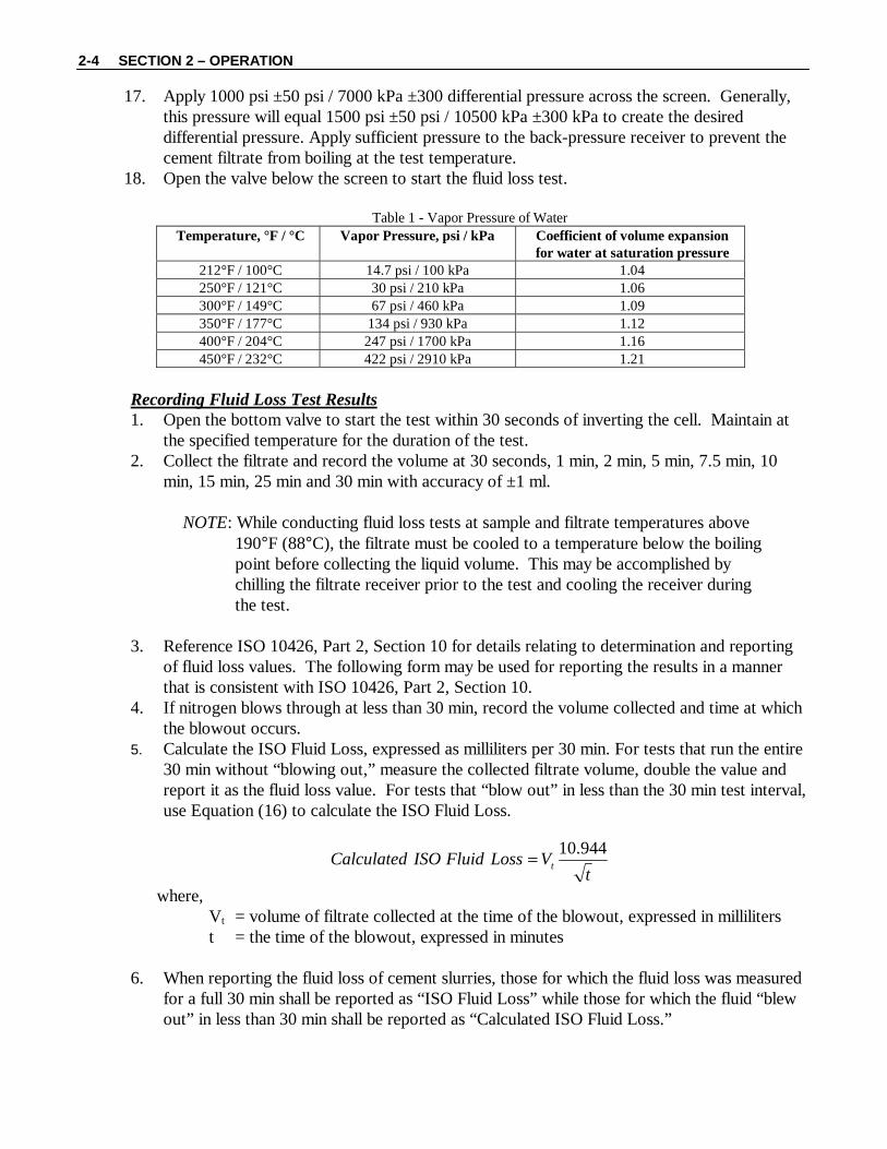
17. Apply 1000 psi ±50 psi / 7000 kPa ±300 differential pressure across the screen. Generally, this pressure will equal 1500 psi ±50 psi / 10500 kPa ±300 kPa to create the desired differential pressure. Apply sufficient pressure to the back-pressure receiver to prevent the cement filtrate from boiling at the test temperature.
18. Open the valve below the screen to start the fluid loss test.
Table 1 - Vapor Pressure of Water Temperature, °F / °C Vapor Pressure, psi / kPa Coefficient of volume expansion
for water at saturation pressure 212°F / 100°C 14.7 psi / 100 kPa 1.04 250°F / 121°C 30 psi / 210 kPa 1.06 300°F / 149°C 67 psi / 460 kPa 1.09 350°F / 177°C 134 psi / 930 kPa 1.12 400°F / 204°C 247 psi / 1700 kPa 1.16 450°F / 232°C 422 psi / 2910 kPa 1.21
Recording Fluid Loss Test Results 1. Open the bottom valve to start the test within 30 seconds of inverting the cell. Maintain at
the specified temperature for the duration of the test. 2. Collect the filtrate and record the volume at 30 seconds, 1 min, 2 min, 5 min, 7.5 min, 10
min, 15 min, 25 min and 30 min with accuracy of ±1 ml.
NOTE: While conducting fluid loss tests at sample and filtrate temperatures above 190°F (88°C), the filtrate must be cooled to a temperature below the boiling point before collecting the liquid volume. This may be accomplished by chilling the filtrate receiver prior to the test and cooling the receiver during the test.
3. Reference ISO 10426, Part 2, Section 10 for details relating to determination and reporting
of fluid loss values. The following form may be used for reporting the results in a manner that is consistent with ISO 10426, Part 2, Section 10.
4. If nitrogen blows through at less than 30 min, record the volume collected and time at which the blowout occurs.
5. Calculate the ISO Fluid Loss, expressed as milliliters per 30 min. For tests that run the entire 30 min without “blowing out,” measure the collected filtrate volume, double the value and report it as the fluid loss value. For tests that “blow out” in less than the 30 min test interval, use Equation (16) to calculate the ISO Fluid Loss.
tVLossFluidISOCalculated t
944.10=
where, Vt = volume of filtrate collected at the time of the blowout, expressed in milliliters t = the time of the blowout, expressed in minutes
6. When reporting the fluid loss of cement slurries, those for which the fluid loss was measured
for a full 30 min shall be reported as “ISO Fluid Loss” while those for which the fluid “blew out” in less than 30 min shall be reported as “Calculated ISO Fluid Loss.”

SECTION 2 - OPERATION 2-5

2-6 SECTION 2 – OPERATION
Fluid Loss Test Completion and Clean-up 1. Cool the cell to a safe handling temperature (35°C or less) and release the pressure. 2. After ensuring that all the pressure is released, remove the cylinder assembly from the heating
jacket.
WARNING: Do not attempt to remove the cylinder end plugs without verifying that all pressure has been vented.
Due to the nature of this equipment and sample, it is possible for pressure to remain in the vessel if the sample has blocked the release ports.
If the end plugs are difficult to remove, assume that the vessel is pressurized and proceed with extreme caution. Orient the cylinder assembly with the bleed holes directed away from the operator. Slowly remove the bottom end plug allowing pressure to vent via the bleed holes.
Always remove the bottom plug first. Do not remove the plug with the filtrate screen first. Refer to the illustration below.
3. Discard the cement slurry, disassemble the cell and inspect the screen to check for holes or
damage. If there is damage to the oring seals or screen, discard the test results and repeat the test.
4. Carefully clean the screen to remove cement or additive residue from all components. 5. Clean and dry the fluid-loss cell in preparation for the next test. Reconnect the pressure hose
to the bottom plug and blow N2 through until all water and residue is removed from the pressure ports. This action ensures that the ports are clear and ready for the next test. If the bleed holes are blocked with sample, clear them before the next test.
6. Verify that the ports in the bottom plug assembly are free from cement. Lubricate the bushings with P-2570 (or equivalent) grease. Clean the impeller stand-pipe. Reassemble the bottom plug assembly, tighten the shaft packing and verify that the impeller shaft turns freely.
Bleed holes oriented away from operator
Unscrew approximately 0.50in, 13mm
SECTION 2 - OPERATION 2-7
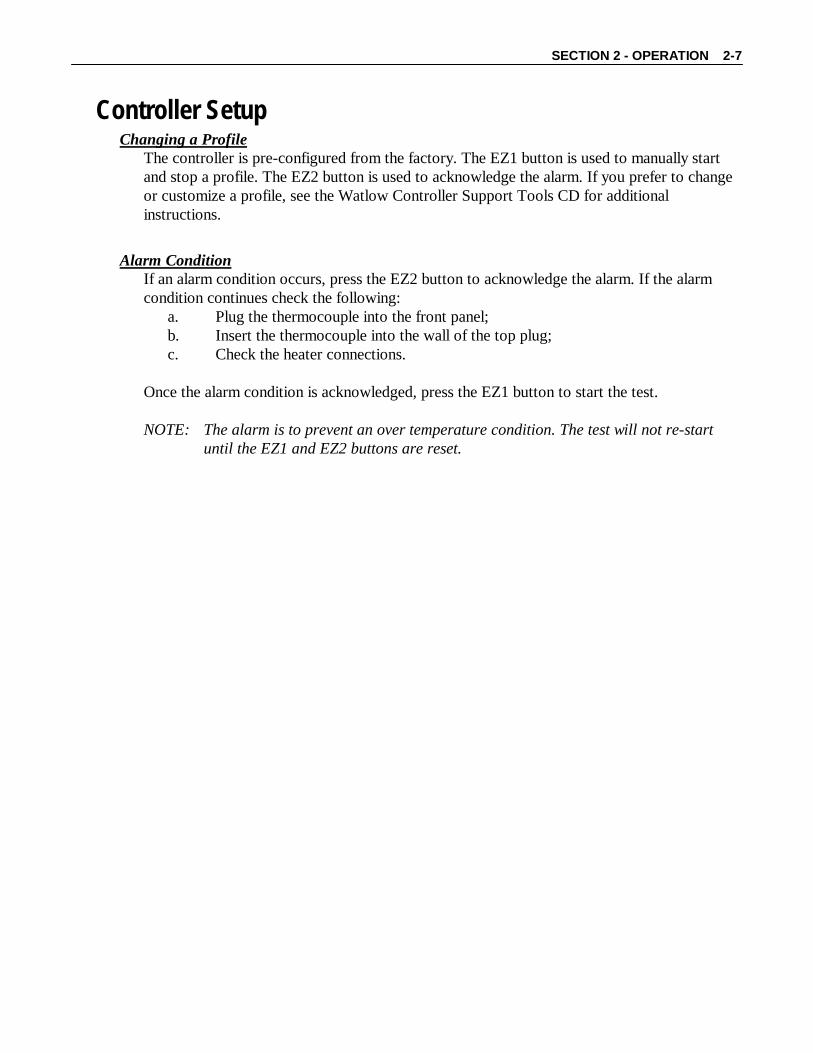
Controller Setup Changing a Profile
The controller is pre-configured from the factory. The EZ1 button is used to manually start and stop a profile. The EZ2 button is used to acknowledge the alarm. If you prefer to change or customize a profile, see the Watlow Controller Support Tools CD for additional instructions.
Alarm Condition
If an alarm condition occurs, press the EZ2 button to acknowledge the alarm. If the alarm condition continues check the following:
a. Plug the thermocouple into the front panel; b. Insert the thermocouple into the wall of the top plug; c. Check the heater connections.
Once the alarm condition is acknowledged, press the EZ1 button to start the test.
NOTE: The alarm is to prevent an over temperature condition. The test will not re-start
until the EZ1 and EZ2 buttons are reset.

2-8 SECTION 2 – OPERATION
This page is intentionally left blank.
SECTION 3 - MAINTENANCE 3-1
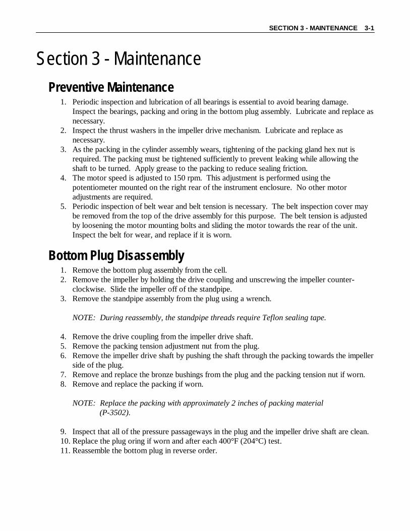
Section 3 - Maintenance Preventive Maintenance
1. Periodic inspection and lubrication of all bearings is essential to avoid bearing damage. Inspect the bearings, packing and oring in the bottom plug assembly. Lubricate and replace as necessary.
2. Inspect the thrust washers in the impeller drive mechanism. Lubricate and replace as necessary.
3. As the packing in the cylinder assembly wears, tightening of the packing gland hex nut is required. The packing must be tightened sufficiently to prevent leaking while allowing the shaft to be turned. Apply grease to the packing to reduce sealing friction.
4. The motor speed is adjusted to 150 rpm. This adjustment is performed using the potentiometer mounted on the right rear of the instrument enclosure. No other motor adjustments are required.
5. Periodic inspection of belt wear and belt tension is necessary. The belt inspection cover may be removed from the top of the drive assembly for this purpose. The belt tension is adjusted by loosening the motor mounting bolts and sliding the motor towards the rear of the unit. Inspect the belt for wear, and replace if it is worn.
Bottom Plug Disassembly 1. Remove the bottom plug assembly from the cell. 2. Remove the impeller by holding the drive coupling and unscrewing the impeller counter-
clockwise. Slide the impeller off of the standpipe. 3. Remove the standpipe assembly from the plug using a wrench.
NOTE: During reassembly, the standpipe threads require Teflon sealing tape. 4. Remove the drive coupling from the impeller drive shaft. 5. Remove the packing tension adjustment nut from the plug. 6. Remove the impeller drive shaft by pushing the shaft through the packing towards the impeller
side of the plug. 7. Remove and replace the bronze bushings from the plug and the packing tension nut if worn. 8. Remove and replace the packing if worn.
NOTE: Replace the packing with approximately 2 inches of packing material (P-3502).
9. Inspect that all of the pressure passageways in the plug and the impeller drive shaft are clean. 10. Replace the plug oring if worn and after each 400°F (204°C) test. 11. Reassemble the bottom plug in reverse order.

3-2 SECTION 3 – MAINTENANCE
This page is intentionally left blank.

SECTION 4 – REPLACEMENT PARTS 4-1
Section 4 - Replacement Parts
Part Number Description 71-0109 Heater Assembly 71-0123 Impeller 71-0162 Gage, Sample Fill C06892 Variable Resistor C07478 Timer C07932 Relay, 440 VAC, 32 VDC C09111 Valve, Needle C09286 Motor C09287 DC Controller C09895 Adapter, 3/8 NPT x 1/4T, SST C12872 Packing, Grafoil,.625X.250 C16434 Temperature Controller P-0397 Wrench, Hex (1/8") P-0417 Terminal Strip, 240V P-0776 Wrench, Hex (3/32") P-0779 Wrench, Hex (5/32") P-2359 Quick Connect Body P-2368 O-Ring (Filtrate Receiver) P-2369 O-Ring (Bottom Cylinder Plug) P-2380 Panel Jack (Thermocouple) P-2383 Thermocouple Cable P-2392 Quick-Connect Stem P-2676 O-Ring (Top Cylinder Stem) P-2701 Heat Sink P-2712 50 ml Graduated Cylinder P-2747 Thermocouple P-2881 Switch, Panel P-3107 Solenoid Valve P-3148 O-Ring (Top Cylinder Plug) P-3156 Filter P-3376 Timing Belt P-3389 Circuit Breaker, 230 VAC version QX-C-1266 Cord, Power
Please give serial number of instrument when ordering Replacement Parts.

4-2 SECTION 4 – REPLACEMENT PARTS
This page is intentionally left blank.

SECTION 5 – DRAWINGS AND SCHEMATICS 5-1
Section 5 – Drawings and Schematics
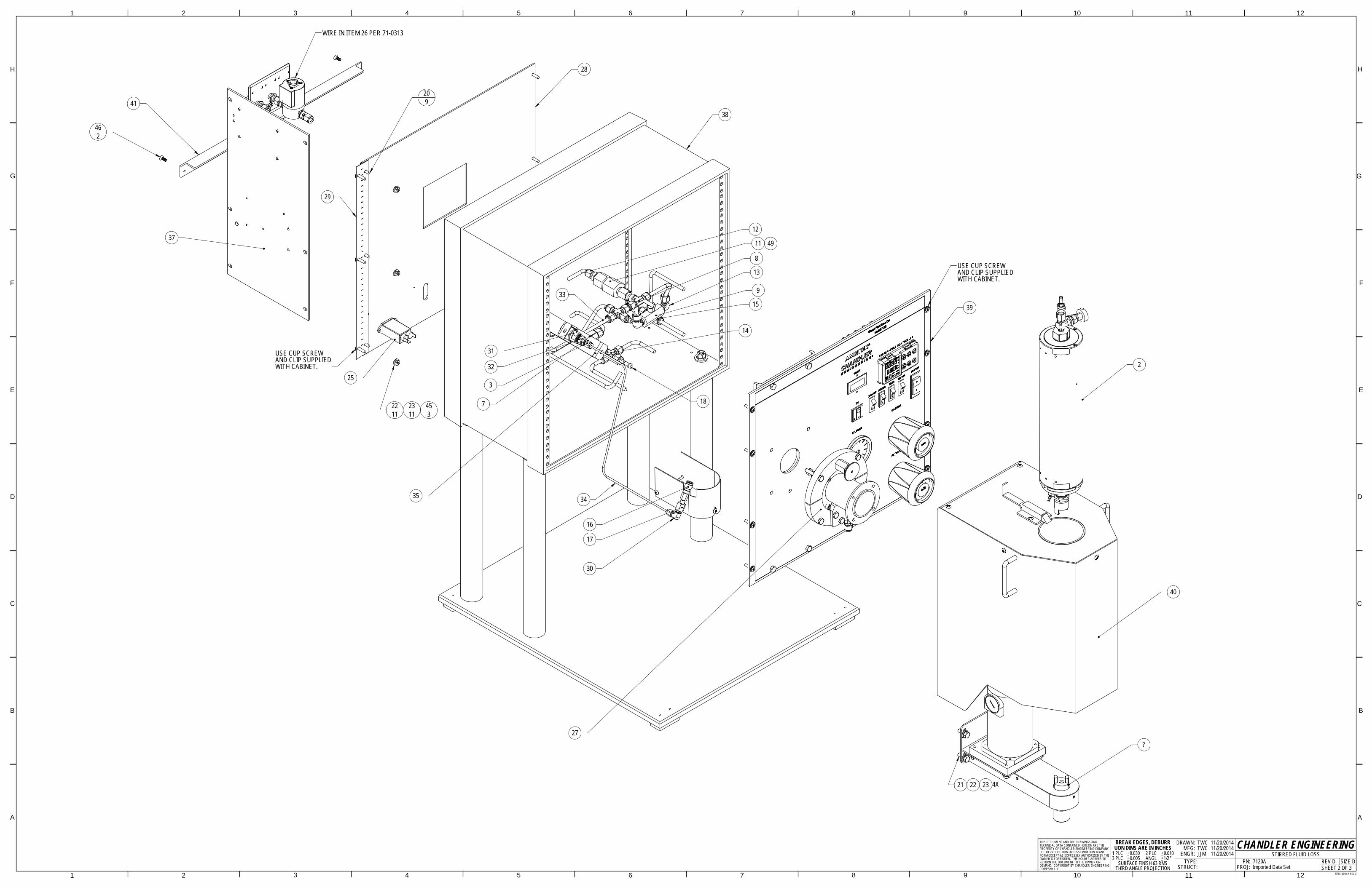
Drawing Number Title 7120A Stirred Fluid Loss 71-0038 Assembly, Index Plunger Knob 71-0074 Filtrate Receiver 71-0110 Top Cap Assembly 71-0115 Cylinder Assembly 71-0130 Impeller Housing Assembly 71-0313 Diagram, Wiring 71-0316 Diagram, Plumbing Declaration of Conformity

5-2 SECTION 5 – DRAWINGS AND SCHEMATICS
This page is intentionally left blank.

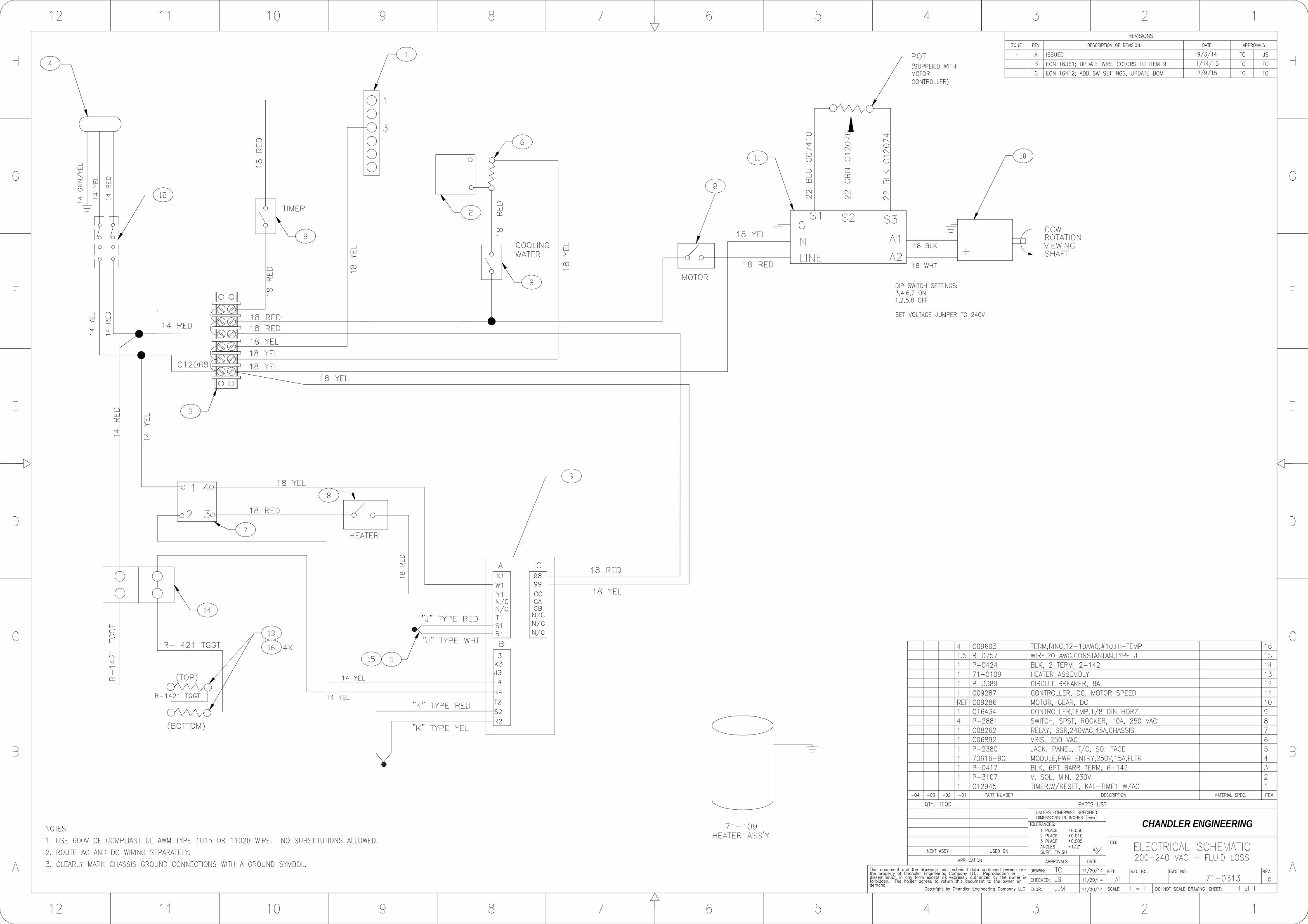
REV DESCRIPTION DATE APPROVEDA ISSUED 05/14/14 LDRB ECN T6412; UPDATED BOM 2/9/15 TCC ECN T6706; REPLACE C09603 W/ C16930 7/29/15 TCD ECN T6958; ADD 71-0057, CHG QTY OF H-
8026 FROM 6 TO 9 12/16/15 TC
ITEM PART NUMBER DESCRIPTION QTY71-0313 WIRING DIAGRAM REF71-0316 PLUMBING DIAGRAM REF
1 71-0039 IMPELLAR DRIVE MECH ASSY 12 71-0115 CYLINDER,ASSY,FLUID LOSS 13 188-13044 CONN,SS,1/8MPX1/8T,SW 14567 C09434 VALVE,RLF,SS,1/4TX1/4T,6000PSI 18 C09998 TEE,BRANCH,SS,1/4TX1/4TX1/8FP 19 P-0586 VALVE,CHK,SS,1/4FX1/4F,5000PSI 1
10 P-0735 TBE ADAPTER, SST, 0.125MP x 0.25T 111 P-1206 SAFETY HEAD,1/4 HIGH PRESSURE 112 P-1389 CONN,SS,3/8MPX1/4T,SW 113 P-1772 ELBOW,SS,1/4MPX1/4T,SW 314 P-1941 CROSS,SS,UN,1/4T,SW 215 P-1942 TEE,UNION,SS,1/4T 116 P-3500 CONN,SS,1/16FPT,QUICK CONN,SW 117 P-3499 ADPTR,RDCG,SS,1/8FPX1/16MP 118 C09704 CONN, PORT, 1/4 419 H-25-001 NUT,HEX,SS,1/4-20 220 H-8026 SCREW,THMS,SS,8-32X0.375,PHIL 921 H-25-019 SCREW,1/4-20X3/4,HHCS,SS 1222 H-10-003 WASHER,FLAT,SS,#10 1123 H-10-002 WSHR,LOCK,SS,#10 1124 H-25-036 NUT,1/4-20,SS,KEPS 825 70616-90 MODULE,PWR ENTRY,250V,15A,FLTR 126 C06892 VARISTOR,250 VAC 127 71-0038 ASSY, INDEX PLUNGER KNOB 128 104888 REAR PANEL, 7120 129 104905 HINGE,BACK PANEL 130 188-08984 ELBOW,SS,1/8MPX1/8T,SW 131 C16286 SWIVEL,1/4"FPX1/4"FP,SS 132 C16249 BUSHING,1/4 NPT X 1/8 NPT, SS 133 7120-TUBE-01 TUBE 1,SWIVEL CONNECTOR 134 7120-TUBE-02 TUBE 2,SWIVEL CONNECTOR 135 105458 BRACKET, SWIVEL, 7120 136 C10000 HOSE,FLEXIBLE METAL,0.25T,24" 237 7120-0300 ELECTRICAL PANEL 138 7120-0201 CHASSIS ASSEMBLY 139 7120-0202 FRONT PANEL ASSEMBLY 140 7120-0203 CYLINDER HOUSING ASSEMBLY 141 7120-0204 REAR BRACKET ASSEMBLY 142 71-0156 WIRING HARNESS, 7120 143 H-4109 SCREW,BHMS,SS,4-40X0.500 244 H-4122 NUT,HEX,4-40,KEPS,SS 245 H-10-101 NUT,HEX,SS,10-32 346 H-10-132 SCREW,FHMS,SS,10-32X0.500 247 C13285 SPRING KIT,YEL,R3A,350-750 148 P-2220 DISK,RUPTURE,2275PSI,.250,IN 149 71-0180 TUBESET, 7120 150 R-0757 WIRE,20 AWG,CONSTANTAN,TYPE J 1.551 C16930 TERM,RING,12-10AWG,#8-10,HI-TEMP 452 R-1421 WIRE,12 AWG,TAN,HI-TEMP,TGGT 7.553 C07410 WIRE,22AWG,BLU,UL1007 .554 C12076 WIRE,22AWG,GRN .555 C12074 WIRE,22AWG,BLK .556 71-0057 SUPPORT COVER,HOUSING 157 71-0180-01 TUBE, REGULATOR TO CROSS REF58 71-0180-02 TUBE, RELEASE VALVE TO CROSS REF59 71-0180-03 TUBE, RELEASE VALVE TO BACK PANEL REF60 71-0180-04 TUBE,SAFETY HEAD TO BACK PANEL REF61 71-0180-05 TUBE,REGULATOR TO CHECK VALVE REF62 71-0180-06 TUBE,CHECK VALVE TO TEE REF63 71-0180-07 TUBE,RELIEF VALVE TO BACK PANEL REF64 71-0180-08 TUBE, REGULATOR TO TEE REF65 71-0180-09 TUBE,REGULATOR TO TEE REF66 71-0180-10 TUBE,NITROGEN INLET TO TEE REF67 71-0180-11 TUBE, FRONT PANEL TO TEE REF
9 10 11
A
876
G
5
H
432
G
12
F
11
E
109
H
PROJ: Imported Data Set PN: 7120A
11/20/2014
SHEET 1 OF 3TITLE BLOCK REV 3
CHANDLER ENGINEERINGSIZE D
DRAWN: TWC
THIRD ANGLE PROJECTIONSURFACE FINISH 63 RMS REV D
1
ENGR: JJM
A
STIRRED FLUID LOSS
1/2
11/20/201411/20/2014
0.005 ANGL
MFG: TWC
STRUCT:
TYPE:
COMPANY LLC
1
D
F
C
B
E
2 3 5 6 7 84
B
C
D
BREAK EDGES, DEBURRUON DIMS ARE IN INCHES
1 PLC 0.030 2 PLC 0.0103 PLC
THIS DOCUMENT AND THE DRAWINGS AND TECHNICAL DATA CONTAINED HEREON ARE THE PROPERTY OF CHANDLER ENGINEERING COMPANY LLC. REPRODUCTION OR DISSEMINATION IN ANY FORM EXCEPT AS EXPRESSLY AUTHORIZED BY THE OWNER IS FORBIDDEN. THE HOLDER AGREES TO RETURN THE DOCUMENT TO THE OWNER ON DEMAND. COPYRIGHT BY CHANDLER ENGINEERING
12
?
49
4138
39
2
40
21 22 23 4X
37
28
29
25
13
9
12
11
8
35
30
16
17
14
3
32
31
7
15
27
34
33
USE CUP SCREWAND CLIP SUPPLIEDWITH CABINET.
USE CUP SCREWAND CLIP SUPPLIEDWITH CABINET.
2211
462
209
2311
453
18
WIRE IN ITEM 26 PER 71-0313
A
1
A
BREAK EDGES, DEBURRUON DIMS ARE IN INCHES
1 PLC 0.030 2 PLC 0.0103 PLC 0.005 ANGL 1/2
SURFACE FINISH 63 RMSTHIRD ANGLE PROJECTION
11/20/201411/20/201411/20/2014
SHEET 2 OF 3TITLE BLOCK REV 3
CHANDLER ENGINEERINGSIZE DREV D
STIRRED FLUID LOSS PN: 7120APROJ: Imported Data Set
DRAWN: TWC MFG: TWC ENGR: JJM TYPE: STRUCT:
THIS DOCUMENT AND THE DRAWINGS AND TECHNICAL DATA CONTAINED HEREON ARE THE PROPERTY OF CHANDLER ENGINEERING COMPANY LLC. REPRODUCTION OR DISSEMINATION IN ANY FORM EXCEPT AS EXPRESSLY AUTHORIZED BY THE OWNER IS FORBIDDEN. THE HOLDER AGREES TO RETURN THE DOCUMENT TO THE OWNER ON DEMAND. COPYRIGHT BY CHANDLER ENGINEERING COMPANY LLC
1
D
F
C
B
E
2 3 5 6 7 84
B
C
D
E
F
G
H
G
H
9 10 11 12
2 3 4 5 6 7 8 9 10 11 12

4863
65
62
58
64
61
59
60
33
CONNECT TO C10000 HOSEAND RUN TO HEATER COOLINGCOIL. ATTACH WITH C07428.SEE 71-0116.
7
A
1
A
BREAK EDGES, DEBURRUON DIMS ARE IN INCHES
1 PLC 0.030 2 PLC 0.0103 PLC 0.005 ANGL 1/2
SURFACE FINISH 63 RMSTHIRD ANGLE PROJECTION
11/20/201411/20/201411/20/2014
SHEET 3 OF 3TITLE BLOCK REV 3
CHANDLER ENGINEERINGSIZE DREV D
STIRRED FLUID LOSS PN: 7120APROJ: Imported Data Set
DRAWN: TWC MFG: TWC ENGR: JJM TYPE: STRUCT:
THIS DOCUMENT AND THE DRAWINGS AND TECHNICAL DATA CONTAINED HEREON ARE THE PROPERTY OF CHANDLER ENGINEERING COMPANY LLC. REPRODUCTION OR DISSEMINATION IN ANY FORM EXCEPT AS EXPRESSLY AUTHORIZED BY THE OWNER IS FORBIDDEN. THE HOLDER AGREES TO RETURN THE DOCUMENT TO THE OWNER ON DEMAND. COPYRIGHT BY CHANDLER ENGINEERING COMPANY LLC
1
D
F
C
B
E
2 3 5 6 7 84
B
C
D
E
F
G
H
G
H
9 10 11 12
2 3 4 5 6 7 8 9 10 11 12
12
1312
11
13
13
11
14 2X
D
D
1. SHIM AS REQUIRED FOR PROPER CLEARANCE TO MINIMIZE PLAY.NOTES:
DATEDESCRIPTIONREV
FPJA05/27/03ISSUED ECN 8506, ADDED NOTE 1E
APPROVED
TC2/9/15ECN T6412, REPL H-25-021 W/ H-25-023
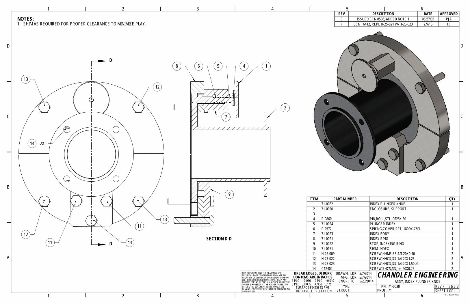
ITEM PART NUMBER DESCRIPTION QTY1 71-0062 INDEX PLUNGER KNOB 12 71-0020 ENCLOSURE, SUPPORT 134 P-0860 PIN,ROLL,STL,.0625X.50 15 71-0024 PLUNGER INDEX 16 P-2572 SPRING,COMPR,SST,.180DX.75FL 17 71-0023 INDEX BODY 18 71-0021 INDEX RING 19 71-0022 STOP, INDEXING RING 1
10 71-0151 SHIM, INDEX 111 H-25-009 SCREW,HHMS,SS,1/4-20X0.50 212 H-25-022 SCREW,HHCS,SS,1/4-20X1.25 213 H-25-023 SCREW,HHCS,SS,1/4-20X1.50LG 314 C12402 SCREW,SHCS,SS,1/4-20X0.25 2
6
9
SECTION D-D
1
2
7
8 45
PN: 71-0038
5 6
A
PROJ: 71SURFACE FINISH 63 RMS
B
THIRD ANGLE PROJECTIONCOMPANY LLC
32
2
D
TYPE:
C
B
D
C
1
REV FSHEET 1 OF 1
5/23/2014
TITLE BLOCK REV 3
ENGR: TC
DRAWN: LDR
4
65
ASSY, INDEX PLUNGER KNOB
A
43
CHANDLER ENGINEERINGSIZE B
1/2
5/7/20145/7/2014
0.005 ANGL
MFG: LDR
STRUCT:
BREAK EDGES, DEBURRUON DIMS ARE IN INCHES
1 PLC 0.030 2 PLC 0.0103 PLC
THIS DOCUMENT AND THE DRAWINGS AND TECHNICAL DATA CONTAINED HEREON ARE THE PROPERTY OF CHANDLER ENGINEERING COMPANY LLC. REPRODUCTION OR DISSEMINATION IN ANY FORM EXCEPT AS EXPRESSLY AUTHORIZED BY THE OWNER IS FORBIDDEN. THE HOLDER AGREES TO RETURN THE DOCUMENT TO THE OWNER ON DEMAND. COPYRIGHT BY CHANDLER ENGINEERING
1
REV.
TC
DESCRIPTION DATE APPROVEDC ECN T2841; MOVED INLET FITTINGS 3/16/2010 JJMD ECN T6412; REPLACE P-1190 WITH P-1487 2/9/2015
D
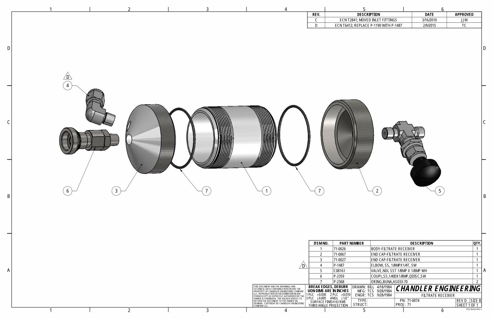
ITEM NO. PART NUMBER DESCRIPTION QTY.1 71-0026 BODY-FILTRATE RECEIVER 12 71-0067 END CAP-FILTRATE RECEIVER 13 71-0027 END CAP-FILTRATE RECEIVER 14 P-1487 ELBOW, SS, 1/8MPX1/4T, SW 15 C08161 VALVE,NDL SST 1/8MP X 1/8MP WH 16 P-2359 COUPL,SS,1/4IDX1/8MP,QDISC,SW 17 P-2368 ORING,BUNA,AS033-70 2
4
9/28/1984
6
4
3
32
TYPE:
2
D
C
B
D
A
C
1
B
COMPANY LLC
PROJ: 71TITLE BLOCK REV 3
9/28/1984 PN: 71-0074
SURFACE FINISH 63 RMS
4/18/1984
0.005 ANGL
SHEET 1 OF 1
CHANDLER ENGINEERING
6
5
ENGR: TCS
DRAWN: BILL MFG: TCS
1/2FILTRATE RECEIVER
5
A
SIZE BSTRUCT:
REV DTHIRD ANGLE PROJECTION
BREAK EDGES, DEBURRUON DIMS ARE IN INCHES
1 PLC 0.030 2 PLC 0.0103 PLC
THIS DOCUMENT AND THE DRAWINGS AND TECHNICAL DATA CONTAINED HEREON ARE THE PROPERTY OF CHANDLER ENGINEERING COMPANY LLC. REPRODUCTION OR DISSEMINATION IN ANY FORM EXCEPT AS EXPRESSLY AUTHORIZED BY THE OWNER IS FORBIDDEN. THE HOLDER AGREES TO RETURN THE DOCUMENT TO THE OWNER ON DEMAND. COPYRIGHT BY CHANDLER ENGINEERING
1
6 573 1 7 2
4D

3
4
1
2
REV. DESCRIPTION DATE APPROVEDE REDESIGNED 03/16/2010 JJM
ITEM PART NUMBER DESCRIPTION QTY1 71-0103 CAP,TOP 12 P-3148 ORING, VITON, PARKER #227 13 P-2392 COUPL,SS,1/4ODX1/8FP,QDISC,SW 14 C08161 VALVE,NDL SST 1/8MP X 1/8MP WH 1
A
1
A
BREAK EDGES, DEBURRUON DIMS ARE IN INCHES
1 PLC 0.030 2 PLC 0.0103 PLC 0.005 ANGL 1/2
SURFACE FINISH 63 RMSTHIRD ANGLE PROJECTION
10/24/200710/30/200710/24/2007
SHEET 1 OF 1TITLE BLOCK REV 3
CHANDLER ENGINEERINGSIZE BREV E
CAP,ASSY,CYL,TOP PN: 71-0110PROJ: 71
DRAWN: JB MFG: TC ENGR: JJM TYPE: STRUCT:
THIS DOCUMENT AND THE DRAWINGS AND TECHNICAL DATA CONTAINED HEREON ARE THE PROPERTY OF CHANDLER ENGINEERING COMPANY LLC. REPRODUCTION OR DISSEMINATION IN ANY FORM EXCEPT AS EXPRESSLY AUTHORIZED BY THE OWNER IS FORBIDDEN. THE HOLDER AGREES TO RETURN THE DOCUMENT TO THE OWNER ON DEMAND. COPYRIGHT BY CHANDLER ENGINEERING COMPANY LLC
B
C
D
B
C
D
2
2 3
3 4 5 6
4 5 61
92
1
8
3
6
4
10
11
12
7
5
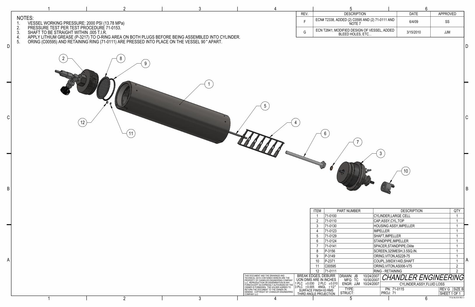
NOTES:VESSEL WORKING PRESSURE: 2000 PSI (13.78 MPa)1.PRESSURE TEST PER TEST PROCEDURE 71-0153.2.SHAFT TO BE STRAIGHT WITHIN .005 T.I.R.3.APPLY LITHIUM GREASE (P-3217) TO O-RING AREA ON BOTH PLUGS BEFORE BEING ASSEMBLED INTO CYLINDER.4.ORING (C00595) AND RETAINING RING (71-0111) ARE PRESSED INTO PLACE ON THE VESSEL 90 APART. 5.
REV. DESCRIPTION DATE APPROVED
F ECN# T2338, ADDED (2) C0595 AND (2) 71-0111 AND NOTE 7 6/4/09 SS
G ECN T2841; MODIFIED DESIGN OF VESSEL, ADDED BLEED HOLES, ETC... 3/15/2010 JJM
ITEM PART NUMBER DESCRIPTION QTY1 71-0100 CYLINDER,LARGE CELL 12 71-0110 CAP,ASSY,CYL,TOP 13 71-0130 HOUSING ASSY,IMPELLER 14 71-0123 IMPELLER 15 71-0129 SHAFT,IMPELLER 16 71-0124 STANDPIPE,IMPELLER 17 71-0141 SPACER,STANDPIPE,Oilite 18 P-3156 SCREEN,325MESH,3.5SQ.IN. 19 P-3149 ORING,VITON,AS228-75 1
10 P-2371 COUPL,3/8IDX1/4ID,SHAFT 111 C00595 ORING,VITON,AS006-V75 212 71-0111 RING - RETAINING 2
A
1
A
BREAK EDGES, DEBURRUON DIMS ARE IN INCHES
1 PLC 0.030 2 PLC 0.0103 PLC 0.005 ANGL 1/2
SURFACE FINISH 63 RMSTHIRD ANGLE PROJECTION
10/24/200710/30/200710/24/2007
SHEET 1 OF 1TITLE BLOCK REV 3
CHANDLER ENGINEERINGSIZE BREV G
CYLINDER,ASSY,FLUID LOSS PN: 71-0115PROJ: 71
DRAWN: JB MFG: TC ENGR: JJM TYPE: STRUCT:
THIS DOCUMENT AND THE DRAWINGS AND TECHNICAL DATA CONTAINED HEREON ARE THE PROPERTY OF CHANDLER ENGINEERING COMPANY LLC. REPRODUCTION OR DISSEMINATION IN ANY FORM EXCEPT AS EXPRESSLY AUTHORIZED BY THE OWNER IS FORBIDDEN. THE HOLDER AGREES TO RETURN THE DOCUMENT TO THE OWNER ON DEMAND. COPYRIGHT BY CHANDLER ENGINEERING COMPANY LLC
B
C
D
B
C
D
2
2 3
3 4 5 6
4 5 61

4
2
7
8
1
5
3
6
REV. DESCRIPTION DATE APPROVEDD ECN T2841; UPDATED DRAWING CONTENT 3/16/2010 JJM
ITEM PART NUMBER DESCRIPTION QTY1 71-0131 CYLINDER PLUG BASE 12 71-0127 PLUG,ADJUSTMENT,PACKING 13 71-0125 SHAFT,IMPELLER,HEAT TREATED 14 P-3497 BEARG,BRZ,1/4IDx3/8ODx1-1/4LG 15 P-3498 BEARG,BRZ,1/4IDx1/4LGx1/2OD 16 P-3148 ORING, VITON, PARKER #227 17 C12872 PACKING, GRAFOIL, .625 X .250 18 P-3501 CONN,SS,1/8ODX1-16MP,QDISC,SW 1
A
1
A
BREAK EDGES, DEBURRUON DIMS ARE IN INCHES
1 PLC 0.030 2 PLC 0.0103 PLC 0.005 ANGL 1/2
SURFACE FINISH 63 RMSTHIRD ANGLE PROJECTION
10/22/200710/30/200710/22/2007
SHEET 1 OF 1TITLE BLOCK REV 3
CHANDLER ENGINEERINGSIZE BREV D
HOUSING ASSY,IMPELLER PN: 71-0130PROJ: 71
DRAWN: JB MFG: TC ENGR: JJM TYPE: STRUCT:
THIS DOCUMENT AND THE DRAWINGS AND TECHNICAL DATA CONTAINED HEREON ARE THE PROPERTY OF CHANDLER ENGINEERING COMPANY LLC. REPRODUCTION OR DISSEMINATION IN ANY FORM EXCEPT AS EXPRESSLY AUTHORIZED BY THE OWNER IS FORBIDDEN. THE HOLDER AGREES TO RETURN THE DOCUMENT TO THE OWNER ON DEMAND. COPYRIGHT BY CHANDLER ENGINEERING COMPANY LLC
B
C
D
B
C
D
2
2 3
3 4 5 6
4 5 61
CHANDLER ENGINEERING

CHANDLER ENGINEERING


AEROSPACE & DEFENSE
2001 North Indianwood Avenue, Broken Arrow, OK 74012 Phone: 918-250-7200 Fax: 918-459-0165
© 2008, by AMETEK, Inc. All rights reserved. e-mail: [email protected] www.chandlereng.com
Model 7120STIRRED FLUID LOSS CELLA Critical Tool for Oil Well Drilling and Cementing
Fluid loss from oilfield muds and cement slurries to a permeable formation can significantly impact their performance or damage the formation. If a cement slurry loses too much fluid, its strength will be compromised and costly remedial well treatments may be needed. The Model 7120 Stirred Fluid Loss Cell measures the fluid loss properties of muds and slurries in accordance with API procedures.
A Vastly Improved, Safer Instrument
Chandler Engineering developed the Model 7120 Stirred Fluid Loss Cell to eliminate safety issues with the traditional instrument designs.
Operational Simplicity and Advanced Capabilities
The Model 7120 is designed to be as easy to use as possible, with clear and intuitive controls. Once the cement slurry or mud is placed into the test cell, a programmable temperature controller increases the temperature at the desired rate. The slurry is conditioned by stirring at 150 rpm similar to a consistometer. The cell is then inverted to begin the fluid loss test. A graduated cylinder or the back pressure receiver is used to collect the filtrate for measurement of the fluid loss characteristics of the slurry.
FEATURES
3 Fluid Loss Measurement Through Standard Screens or Core Samples
3 Safer Approach—No Need to Transfer Hot Slurry
3 Quick Turnaround for Multiple Tests
Printed in the U.S.A. © 2008, by AMETEK, Inc. All rights reserved. XM808PDF (360000)
2001 North Indianwood Avenue, Broken Arrow, OK 74012 Tel: +1 918-250-7200 Fax: +1 918-459-0165e-mail: [email protected] www.chandlereng.com
Houston Sales and Services4903 W. Sam Houston Parkway, N., Suite A-400, Houston, TX 77041 Tel: +1 713-466-4900 Fax: +1 713-849-1924
Model 7120
Specifications
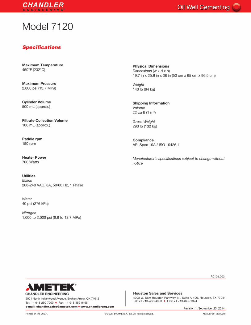
Maximum Temperature450°F (232°C)
Maximum Pressure 2,000 psi (13.7 MPa)
Cylinder Volume 500 mL (approx.)
Filtrate Collection Volume 100 mL (approx.)
Paddle rpm150 rpm
Heater Power700 Watts
UtilitiesMains208-240 VAC, 8A, 50/60 Hz, 1 Phase
Water40 psi (276 kPa)
Nitrogen1,000 to 2,000 psi (6.8 to 13.7 MPa)
Physical DimensionsDimensions (w x d x h)19.7 in x 25.6 in x 38 in (50 cm x 65 cm x 96.5 cm)
Weight 140 lb (64 kg)
Shipping Information Volume 22 cu ft (1 m3)
Gross Weight290 lb (132 kg)
ComplianceAPI Spec 10A / ISO 10426-I
Manufacturer's specifications subject to change without notice
R0109.002
Revision 1, September 23, 2014


![Characterization of a 5 Litre Continuous Stirred Tank Reactorthe ideal RTD for a continuous stirred tank reactor [7]. Continuous stirred tanks are used ubiquitously in the chemical](https://static.fdocuments.us/doc/165x107/5e6e9e407b6f221ce170ace0/characterization-of-a-5-litre-continuous-stirred-tank-reactor-the-ideal-rtd-for.jpg)