INSTRUCTION MANUAL · MiMi 180 is a logging microprocessor-based pH, ORP, EC, TDS, NaCl and...
44
www.milwaukeetesters.com 1 Multiparameter Bench Meter Multiparameter Bench Meter Multiparameter Bench Meter Multiparameter Bench Meter Multiparameter Bench Meter Mi 180 pH/mV/EC/TDS/NaCl/T pH/mV/EC/TDS/NaCl/T pH/mV/EC/TDS/NaCl/T pH/mV/EC/TDS/NaCl/T pH/mV/EC/TDS/NaCl/Temperature emperature emperature emperature emperature INSTRUCTION MANUAL www.milwaukeeinst.com
Transcript of INSTRUCTION MANUAL · MiMi 180 is a logging microprocessor-based pH, ORP, EC, TDS, NaCl and...

www.milwaukeetesters.com
1
Multiparameter Bench MeterMultiparameter Bench MeterMultiparameter Bench MeterMultiparameter Bench MeterMultiparameter Bench Meter
Mi 180pH/mV/EC/TDS/NaCl/TpH/mV/EC/TDS/NaCl/TpH/mV/EC/TDS/NaCl/TpH/mV/EC/TDS/NaCl/TpH/mV/EC/TDS/NaCl/Temperatureemperatureemperatureemperatureemperature
INSTRUCTION MANUAL
www.milwaukeeinst.com

Instruction Manual Mi 180 Bench Meter
22222
FUNCTIONAL DESCRIPTION ............................................................................................ 2GENERAL DESCRIPTION ................................................................................................... 4SPECIFICATIONS .............................................................................................................. 5OPERATIONAL GUIDE ..................................................................................................... 7AUTORANGING ............................................................................................................. 11pH CALIBRATION ........................................................................................................... 12pH BUFFER TEMPERATURE DEPENDENCE ........................................................................ 15RELATIVE mV CALIBRATION ............................................................................................. 16EC/TDS CALIBRATION ..................................................................................................... 17NaCl CALIBRATION ........................................................................................................ 18GOOD LABORATORY PRACTICE (GLP) ............................................................................ 19LOGGING .................................................................................................................... 25SETUP ............................................................................................................................ 33mV CALIBRATION ........................................................................................................... 35TEMPERATURE CALIBRATION .......................................................................................... 36EC SOLUTIONS TEMPERATURE DEPENDENCE ................................................................. 37PC INTERFACE ............................................................................................................... 38ELECTRODE CONDITIONING & MAINTENANCE ............................................................. 40TROUBLESHOOTING ..................................................................................................... 42ACCESSORIES ................................................................................................................ 43
DISPLAYDISPLAYDISPLAYDISPLAYDISPLAY
A. PRIMARY DISPLAYB. MEASURING UNIT FOR PRIMARY
DISPLAYC. CALIBRATION MESSAGESD. MEMORIZED pH CALIBRATION
BUFFERSE. CALIBRATION TAGSF. GLP TAGSG. MODE INDICATORSH. REQUIRE USER CONFIRMATIONI. CALIBRATION REQUESTEDJ. SECONDARY DISPLAYK. MEASURING UNIT FOR SECONDARY
DISPLAYL. TEMPERATURE COMPENSATION
MODE INDICATORM. CALIBRATION MESSAGESN. MEASURING UNIT FOR PRIMARY
DISPLAY
FUNCTIONAL DESCRIPTION
B
A
C
D
E
G
F
H
I
J
K
L
M
N

www.milwaukeeinst.com
3
FUNCTIONAL DESCRIPTION
RS 232
POWER
12VDC
USB
EC
TEMP
REF
1516
17
1913
1418
FRONT PANELFRONT PANELFRONT PANELFRONT PANELFRONT PANEL
1. Liquid Crystal Display (LCD)2. CAL key, to enter/exit calibration mode3. GLP/ACCEPT key, to display GLP data
or to confirm value4. SHIFT key, to select second key function5. LOG/CLR/MR key, to store reading in
memory, to clear calibration or to en-ter/exit recall mode
6. MODE/SETUP key, to select measure-ment mode/pH resolution, to enter/exit setup mode or to toggle betweendelete one or all logged data
7. /ATC key, to manually decrease tem-perature value or other parameters or toselect temperature compensation mode
8. RANGE/FIXED key, to switch measure-ment unit pH/mV/EC or focused data,or to freeze current reading on the LCD
9. /TC key, to manually increase tem-perature value or other parameters orto view temperature coefficient value
10. ON/OFF key, to turn the meter ONand OFF
11. Secondary LCD12. Primary LCD
REAR PANELREAR PANELREAR PANELREAR PANELREAR PANEL
13. USB connector14. RS232 connector15. Power supply socket16. DIN connector for EC probe17. Reference pH electrode socket18. BNC pH electrode connector19. Temperature probe socket
12
11
10
9
8
7
6
5
4
3
2
1
Instruction Manual Mi 180 Bench Meter
44444
GENERAL DESCRIPTION
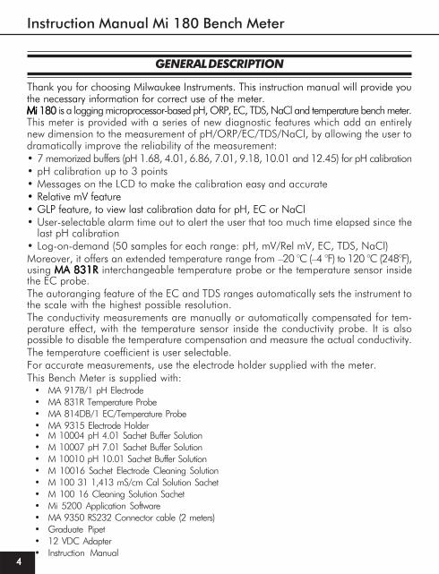
Thank you for choosing Milwaukee Instruments. This instruction manual will provide you the necessary information for correct use of the meter.Mi Mi 180 is a logging microprocessor-based pH, ORP, EC, TDS, NaCl and temperature bench meter. This meter is provided with a series of new diagnostic features which add an entirely new dimension to the measurement of pH/ORP/EC/TDS/NaCl, by allowing the user to dramatically improve the reliability of the measurement:• 7 memorized buffers (pH 1.68, 4.01, 6.86, 7.01, 9.18, 10.01 and 12.45) for pH calibration• pH calibration up to 3 points• Messages on the LCD to make the calibration easy and accurate• Relative mV feature• GLP feature, to view last calibration data for pH, EC or NaCl• User-selectable alarm time out to alert the user that too much time elapsed since the
last pH calibration• Log-on-demand (50 samples for each range: pH, mV/Rel mV, EC, TDS, NaCl)Moreover, it offers an extended temperature range from –20 °C (–4 °F) to 120 °C (248°F),using MA 831RMA 831RMA 831RMA 831RMA 831R interchangeable temperature probe or the temperature sensor insidethe EC probe.The autoranging feature of the EC and TDS ranges automatically sets the instrument tothe scale with the highest possible resolution.The conductivity measurements are manually or automatically compensated for tem-perature effect, with the temperature sensor inside the conductivity probe. It is alsopossible to disable the temperature compensation and measure the actual conductivity.The temperature coefficient is user selectable.For accurate measurements, use the electrode holder supplied with the meter.This Bench Meter is supplied with:
• MA 917B/1 pH Electrode• MA 831R Temperature Probe• MA 814DB/1 EC/Temperature Probe• MA 9315 Electrode Holder• M 10004 pH 4.01 Sachet Buffer Solution• M 10007 pH 7.01 Sachet Buffer Solution• M 10010 pH 10.01 Sachet Buffer Solution• M 10016 Sachet Electrode Cleaning Solution• M 100 31 1,413 mS/cm Cal Solution Sachet• M 100 16 Cleaning Solution Sachet• Mi 5200 Application Software• MA 9350 RS232 Connector cable (2 meters)• Graduate Pipet• 12 VDC Adapter• Instruction Manual

www.milwaukeeinst.com
5
SPECIFICATIONS
Range pH -2.00 to 16.00 pH / -2.000 to 16.000 pHmV ±699.9 mV / ±2000 mVEC 0.00 to 29.99 μS/cm
30.0 to 299.9 μS/cm300 to 2999 μS/cm3.00 to 29.99 mS/cm30.0 to 200.0 mS/cmup to 500.0 mS/cm (uncompensated EC)*
TDS 0.00 to 14.99 mg/L (ppm)15.0 to 149.9 mg/L (ppm)150 to 1499 mg/L (ppm)1.50 to 14.99 g/L (ppt)15.0 to 100.0 g/L (ppt)up to 400.0 g/L (uncompensated TDS)* with 0.80 conversion factor
NaCl 0.0 to 400.0%Temp -20.0 to 120.0 °C (-4.0 to 248.0 °F)
Resolution pH 0.01 pH / 0.001 pHmV 0.1 mV / 1 mVEC 0.01 μS/cm
0.1 μS/cm1 μS/cm0.01 mS/cm0.1 mS/cm
TDS 0.01 mg/L0.1 mg/L1mg/L0.01 g/L0.1 g/L
NaCl 0.1%Temp 0.1 °C (0.1 °F)
(*) Uncompensated conductivity (or TDS) is the conductivity (or TDS) value without temperature compensation.
Instruction Manual Mi 180 Bench Meter
66666
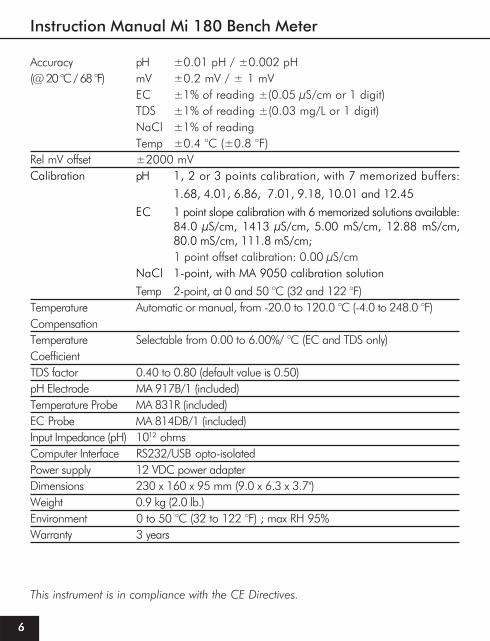
Accuracy pH ±0.01 pH / ±0.002 pH(@ 20 °C / 68 °F) mV ±0.2 mV / ± 1 mV
EC ±1% of reading ±(0.05 μS/cm or 1 digit)TDS ±1% of reading ±(0.03 mg/L or 1 digit)NaCl ±1% of readingTemp ±0.4 °C (±0.8 °F)
Rel mV offset ±2000 mVCalibration pH 1, 2 or 3 points calibration, with 7 memorized buffers:
1.68, 4.01, 6.86, 7.01, 9.18, 10.01 and 12.45
EC 1 point slope calibration with 6 memorized solutions available:84.0 μS/cm, 1413 μS/cm, 5.00 mS/cm, 12.88 mS/cm,80.0 mS/cm, 111.8 mS/cm;1 point offset calibration: 0.00 μS/cm
NaCl 1-point, with MA 9050 calibration solution
Temp 2-point, at 0 and 50 °C (32 and 122 °F)Temperature Automatic or manual, from -20.0 to 120.0 °C (-4.0 to 248.0 °F)CompensationTemperature Selectable from 0.00 to 6.00%/ °C (EC and TDS only)CoefficientTDS factor 0.40 to 0.80 (default value is 0.50)pH Electrode MA 917B/1 (included)Temperature Probe MA 831R (included)EC Probe MA 814DB/1 (included)Input Impedance (pH) 1012 ohmsComputer Interface RS232/USB opto-isolatedPower supply 12 VDC power adapterDimensions 230 x 160 x 95 mm (9.0 x 6.3 x 3.7")Weight 0.9 kg (2.0 lb.)Environment 0 to 50 °C (32 to 122 °F) ; max RH 95%Warranty 3 years
This instrument is in compliance with the CE Directives.

www.milwaukeeinst.com
7
OPERATIONAL GUIDE
INITIAL PREPARATIONINITIAL PREPARATIONINITIAL PREPARATIONINITIAL PREPARATIONINITIAL PREPARATIONPlug the 12 VDC adapter to the power supply socket. To prepare the instrument for pHmeasurements, connect the pH electrode to the BNC connector and the temperatureprobe to the appropriate socket on the rear panel of the instrument. The temperatureprobe is used in conjunction with the pH electrode to utilize the instrument's ATCcapability, but it can also be used independently to take temperature measurements.For electrodes with a separate reference, connect the electrode’s BNC to the BNCconnector and plug the reference electrode to the reference socket.For temperature measurements and pH automatic temperature compensation connect thetemperature probe to the appropriate socket. After taking measurements switch the meteroff, clean the electrode and store it with a few drops of MA 9015 MA 9015 MA 9015 MA 9015 MA 9015 storage solution in theprotection cap.For EC/TDS measurements connect the EC probe to the 7-pin connector. Make sure theprobe sleeve is properly inserted and tighten the threaded ring.The instrument enters the same range and mode as it was at power off. For pH and mV/Rel mVmodes, after turning the instrument on, the “OPEN” tag and the “ ” and “ ” symbols from theelectrode blink on the LCD for a few seconds to remind the user to unscrew the electroderefilling cap, and to remove the protective cap before taking measurements.
pHpHpHpHpH MEASUREMENTS MEASUREMENTS MEASUREMENTS MEASUREMENTS MEASUREMENTS
Make sure the instrument has been calibrated before taking pH measurements.• If necessary, press the RANGE key until the display changes to pH mode.• Submerge the tip of the electrode (4cm/1½") and the temperature probe into the sample
to be tested and stir gently. Allow for the electrode to stabilize.• The pH measurement is displayed on the primary LCD and the temperature on the secondary LCD.
• If the reading is out of range, the closest full-scale value will blink on the primary LCD.

Instruction Manual Mi 180 Bench Meter
88888
The display will show the default temperature of 25 °C or the last temperature reading withthe “MTC” tag and “°C” (or “°F”) tag blinking.
The temperature can now be adjusted with the UP and DOWN arrow keys (from –20.0 °C to120.0 °C).
mmmmmV / REL V / REL V / REL V / REL V / REL mmmmmV MEASUREMENTSV MEASUREMENTSV MEASUREMENTSV MEASUREMENTSV MEASUREMENTS
An optional ORP electrode must be used to perform ORP measurements (see “Accessories” section).Oxidation-Reduction Potential (ORP) measurements provide the quantification of the oxidizing orreducing power of the tested sample.To perform an ORP measurement correctly, the surface of the electrode must be clean andsmooth.• If necessary, press the RANGE/FIXED key until the display changes to mV/Rel mV.• Submerge the ORP electrode tip (4cm/1½") into the sample to be tested and allow a
few seconds for the reading to stabilize.• The instrument displays the mV reading on the primary LCD or Rel mV reading if a Rel mV
calibration has been performed and the temperature on the secondary LCD.
NoteNoteNoteNoteNote: To change pH resolution press the MODE/SETUP key.If measurements are taken successively in different samples, it is recommended to rinse theelectrode thoroughly with deionizated water and then with some of the sample to be tested.The pH reading is affected by temperature. In order to measure the pH accurately, thetemperature effect must be compensated. To use the Automatic Temperature Compensation(ATC) feature, connect and submerge the MA 831RMA 831RMA 831RMA 831RMA 831R temperature probe into the sample asclose as possible to the electrode and wait for a few seconds. The “ATC” tag will bedisplayed.
If Manual Temperature Compensation (MTC) is desired, the temperature probe must bedisconnected from the instrument.

www.milwaukeeinst.com
9
NotesNotesNotesNotesNotes:•When the reading is out of range, the closest full-scale value is displayed blinking.•If using a pH electrode while in mV mode, the instrument will measure the mV generated
by the pH electrode.•If the instrument displays a Rel mV reading and it is desired to take mV measurements,
simply clear the Rel mV calibration (see Rel mV calibration section at page 16).
CONDUCTIVITYCONDUCTIVITYCONDUCTIVITYCONDUCTIVITYCONDUCTIVITY MEASUREMENTS MEASUREMENTS MEASUREMENTS MEASUREMENTS MEASUREMENTS
Make sure the instrument has been calibrated before taking conductivity measurements.• Press the RANGE/FIXED key to enter EC measurement mode.• Immerse the probe into the solution to be tested. The sleeve holes must be completely submerged.
Tap the probe repeatedly to remove any air bubbles that may be trapped inside the sleeve.• The conductivity value is displayed on the primary LCD and the temperature on the secondary
LCD, along with the reference temperature.
NotesNotesNotesNotesNotes:•If the reading is out of range, the closest full-scale value (200.0 mS for MTC/ATC mode or
500.0 mS for uncompensated conductivity) will be displayed blinking.•If SHIFT&RANGE/FIXED keys are pressed to freeze the LCD range and the reading goes
out of range, the full-scale value of the frozen range will be displayed blinking.The EC reading is affected by temperature. Three options for temperature compensation areavailable in EC measurement mode.
or

Instruction Manual Mi 180 Bench Meter
1 01 01 01 01 0
NoteNoteNoteNoteNote: The compensation is referenced at the selected reference temperature (seeSETUP for details, page 33).
Automatic (ATC): The EC probe has a built-in temperature sensor; the temperature value isused to automatically compensate the EC/TDS reading (from -20.0 – 120.0 °C).Manual (MTC): The temperature value, shown on the secondary LCD, can be manually setwith the UP and DOWN arrow keys. The “°C” tag blinks when this option is active.No Compensation (NOTC): The temperature value is displayed, but it is not takeninto account. The reading displayed on the primary LCD is the uncompensated EC or TDSvalue. To select the desired option, press the SHIFT& /ATC keys until the option isdisplayed on the LCD.
NotesNotesNotesNotesNotes:
•The default compensation mode is ATC.
•If no temperature probe is detected, ATC mode can not be selected and the instru-ment displays “----” on the secondary LCD.
If temperature compensation is active, measurements are compensated using the tem-perature coefficient (default value 1.90 %/°C). To change the temperature coefficient,enter the setup mode and select the “tc” item (see SETUP for details, page 33). Thecurrent temperature coefficient can be quickly viewed by pressing the SHIFT& /TC keys.The value is briefly displayed on the secondary LCD.• If the temperature reading is out of the -20.0 to 120.0 °C (-4.0 to 248.0 °F) interval and ATC
option is selected, the “°C” tag will blink and the closest interval limit will be displayed.• By pressing the UP and DOWN arrow keys the displayed temperature value can be
changed. This value is used to compensate the EC/TDS reading.
TDSTDSTDSTDSTDS MEASUREMENTS MEASUREMENTS MEASUREMENTS MEASUREMENTS MEASUREMENTS
• Press the MODE/SETUP key while in EC range until the display changes to TDS mode.• The TDS reading will be displayed on the primary LCD and the temperature reading on
the secondary LCD, along with the reference temperature.

www.milwaukeeinst.com
11
NotesNotesNotesNotesNotes:
•If the reading is out of range, the full-scale value (160.0 g/L for MTC/ATC mode or400.0 g/L for uncompensated TDS) will be displayed blinking.
•If the SHIFT&RANGE/FIXED keys are pressed to freeze the LCD range and the readinggoes out of range, the full-scale value of the frozen range will be displayed blinking.
NaClNaClNaClNaClNaCl MEASUREMENTS MEASUREMENTS MEASUREMENTS MEASUREMENTS MEASUREMENTS
• Press the MODE/SETUP key while in EC range to enter NaCl measurement mode.• The instrument will display the NaCl reading on the primary LCD and the temperature on the
secondary LCD, along with the reference temperature.
AUTORANGING
The EC and TDS scales are autoranging. The meter automatically sets the scale with thehighest possible resolution.By pressing the SHIFT&RANGE/FIXED keys, the autoranging feature is disabled and thecurrent range is frozen on the LCD. The “Auto” “OFF” (autoranging disabled) messagewill be displayed on the LCD for a few seconds. To restore the autoranging option,press the SHIFT&RANGE/FIXED keys again. The “Auto” “On” (autoranging enabled)message will be displayed on the LCD for a few seconds.
NoteNoteNoteNoteNote: Autoranging is automatically restored if the range is changed, if the setup orcalibration modes are entered and if the meter is turned off and back on again.

Instruction Manual Mi 180 Bench Meter
1 21 21 21 21 2
pH CALIBRATION
It is recommended to calibrate the instrument frequently, especially if high accuracy is required.The pH calibration is also necessary in the following cases:a) Whenever the pH electrode is replaced.b) At least once a week.c) After testing aggressive chemicals.d) When extreme accuracy is required.e) If “CALIBRATION EXPIRED” tag is blinking during measurement.Every time you calibrate the instrument use fresh buffers and perform an electrode CleaningProcedure (see page 41).
PROCEDUREPROCEDUREPROCEDUREPROCEDUREPROCEDUREOne, two or three points calibration can be performed, from the 7 memorized buffers (1.68,4.01, 6.86, 7.01, 9.18, 10.01 and 12.45 pH).• Pour small quantities of selected buffer solutions into clean beakers. For accurate calibration
use two beakers for each buffer solution, the first one to rinse the electrode and the secondone for calibration.
• Remove the protective cap and rinse the electrode with some of the buffer solution to beused for the first calibration point.
THREE-POINT CALIBRATIONTHREE-POINT CALIBRATIONTHREE-POINT CALIBRATIONTHREE-POINT CALIBRATIONTHREE-POINT CALIBRATION
• Immerse the pH electrode and the temperature probe approximately 4 cm (1½”) into a buffersolution of your choice (pH 1.68, 4.01, 6.86, 7.01, 9.18, 10.01 or 12.45) and stir gently. Thetemperature probe should be close to the pH electrode.
• Press the CAL key. The “CAL”, “1” and “CALIBRATION” tags will appear and thesecondary LCD will display buffer “7.01”.
www.milwaukeeinst.com
13
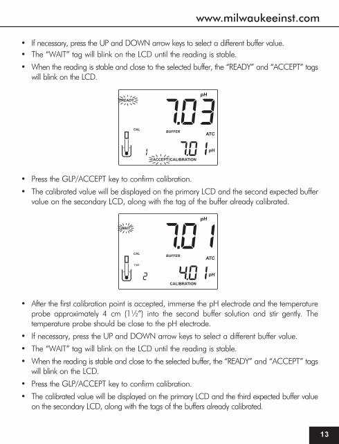
• If necessary, press the UP and DOWN arrow keys to select a different buffer value.• The “WAIT” tag will blink on the LCD until the reading is stable.
• When the reading is stable and close to the selected buffer, the “READY” and “ACCEPT” tagswill blink on the LCD.
• Press the GLP/ACCEPT key to confirm calibration.
• The calibrated value will be displayed on the primary LCD and the second expected buffervalue on the secondary LCD, along with the tag of the buffer already calibrated.
• After the first calibration point is accepted, immerse the pH electrode and the temperatureprobe approximately 4 cm (1½”) into the second buffer solution and stir gently. Thetemperature probe should be close to the pH electrode.
• If necessary, press the UP and DOWN arrow keys to select a different buffer value.
• The “WAIT” tag will blink on the LCD until the reading is stable.
• When the reading is stable and close to the selected buffer, the “READY” and “ACCEPT” tagswill blink on the LCD.
• Press the GLP/ACCEPT key to confirm calibration.
• The calibrated value will be displayed on the primary LCD and the third expected buffer valueon the secondary LCD, along with the tags of the buffers already calibrated.

Instruction Manual Mi 180 Bench Meter
1 41 41 41 41 4
• After the second calibration point is accepted, immerse the pH electrode and the tempera-ture probe approximately 4 cm (1½”) into the third buffer solution and stir gently. Thetemperature probe should be close to the pH electrode.
• If necessary, press the UP and DOWN arrow keys to select a different buffer value.
• The “WAIT” tag will blink on the LCD until the reading is stable.
• When the reading is stable and close to the selected buffer, the “READY” and “ACCEPT” tagswill blink on the LCD.
• Press the GLP/ACCEPT key to confirm calibration.
• The instrument stores the calibration values and returns to normal measurement mode.
NotesNotesNotesNotesNotes:
•The instrument automatically skips the buffers already used for the previous calibration points toavoid erroneous procedure.
•If the value measured by the instrument is not close to the selected buffer, “WRONG BUFFER”and “WRONG PROBE” messages will blink alternately. In this case, check if the correct bufferhas been used or regenerate the electrode by following the Cleaning Procedure (see page 40).If necessary, change the buffer or the electrode.
•If “WRONG BUFFER” and “Old” messages on the secondary LCD are displayed blinking, aninconsistency between new and previous (old) calibration is detected. Clear calibrationparameters by pressing the LOG/CLR/MR key and proceed with calibration from the currentcalibration point (the instrument will keep all confirmed values during current calibration).
•The “WRONG BUFFER” message and the temperature value blink if temperature reading isout of the defined temperature range for the buffer. Calibration cannot be confirmed in thissituation.
•Press the RANGE/FIXED key to display the temperature reading during calibration.•To clear a previous calibration and return to the default values, press the LOG/CLR/MR key at
any time after entering calibration mode. The LCD will show “CLr CAL” for one second, and thenthe meter will return to normal measurement mode.
www.milwaukeeinst.com
15
1 OR 2 POINT CALIBRATION
• Proceed as described in “Three-point calibration” section.
• Press the CAL key after the appropriate calibration point is accepted.
The instrument will return to measurement mode, will memorize the calibration data, and theappropriate tags for the calibrated buffers will be displayed on the LCD only if the “disp” optionfrom the SETUP menu is ON (see page 33).
pH BUFFER TEMPERATURE DEPENDENCE
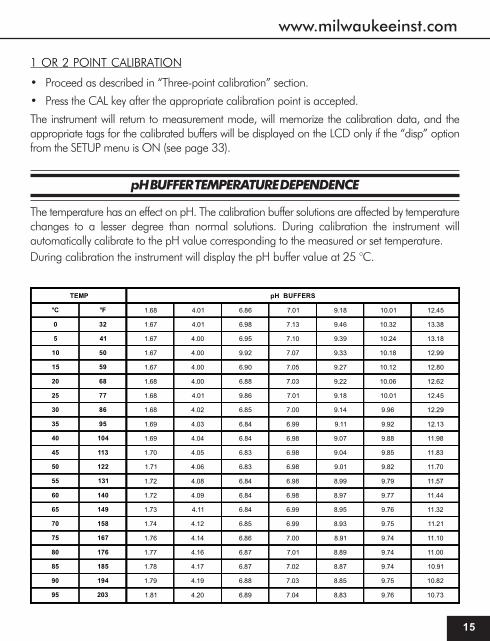
The temperature has an effect on pH. The calibration buffer solutions are affected by temperaturechanges to a lesser degree than normal solutions. During calibration the instrument willautomatically calibrate to the pH value corresponding to the measured or set temperature.During calibration the instrument will display the pH buffer value at 25 °C.
TEMP pH BUFFERS
°C °F 1.68 4.01 6.86 7.01 9.18 10.01 12.45
0 32 1.67 4.01 6.98 7.13 9.46 10.32 13.38
5 41 1.67 4.00 6.95 7.10 9.39 10.24 13.18
10 50 1.67 4.00 9.92 7.07 9.33 10.18 12.99
15 59 1.67 4.00 6.90 7.05 9.27 10.12 12.80
20 68 1.68 4.00 6.88 7.03 9.22 10.06 12.62
25 77 1.68 4.01 9.86 7.01 9.18 10.01 12.45
30 86 1.68 4.02 6.85 7.00 9.14 9.96 12.29
35 95 1.69 4.03 6.84 6.99 9.11 9.92 12.13
40 104 1.69 4.04 6.84 6.98 9.07 9.88 11.98
45 113 1.70 4.05 6.83 6.98 9.04 9.85 11.83
50 122 1.71 4.06 6.83 6.98 9.01 9.82 11.70
55 131 1.72 4.08 6.84 6.98 8.99 9.79 11.57
60 140 1.72 4.09 6.84 6.98 8.97 9.77 11.44
65 149 1.73 4.11 6.84 6.99 8.95 9.76 11.32
70 158 1.74 4.12 6.85 6.99 8.93 9.75 11.21
75 167 1.76 4.14 6.86 7.00 8.91 9.74 11.10
80 176 1.77 4.16 6.87 7.01 8.89 9.74 11.00
85 185 1.78 4.17 6.87 7.02 8.87 9.74 10.91
90 194 1.79 4.19 6.88 7.03 8.85 9.75 10.82
95 203 1.81 4.20 6.89 7.04 8.83 9.76 10.73

Instruction Manual Mi 180 Bench Meter
1 61 61 61 61 6
RELATIVE mV CALIBRATION
• Press the CAL key when the instrument is in mV / Rel mV measurement mode. The“CALIBRATION” tag will appear on the LCD.
• Relative mV value is displayed on the primary LCD and the absolute mV value on thesecondary LCD.
• The “WAIT” tag will blink until the reading is stable.
• When the absolute reading is stable and in measurement range, the “READY” and “AC-CEPT” tags blink on the LCD, asking for confirmation.
• If the reading is out of range, the absolute mV value and the “WRONG” tag will blink.
• Press the GLP/ACCEPT key to confirm the calibration. The instrument enters Rel mVmeasurement mode.
NotesNotesNotesNotesNotes:
•If a Rel mV calibration is performed, the range changes from mV to Rel mV.
•To return to mV measurement mode, clear the Rel mV calibration by pressing LOG/CLR/MRafter entering calibration mode. The “CLr CAL” message will appear on the LCD for onesecond and the instrument will enter mV measurement mode.

www.milwaukeeinst.com
17
EC/TDS CALIBRATION
EC calibration is a one-point procedure. Selectable calibration points are 0.00 μS foroffset and 84.0 μS, 1413 μS, 5.00 mS, 12.88 mS, 80.0 mS, 111.8 mS for slope.Rinse the probe with calibration solution or deionized water. Immerse the probe into thesolution. The sleeve holes must be completely submerged. Tap the probe repeatedly toremove any air bubbles that may be trapped inside the sleeve.To enter EC calibration, select the EC range and press CAL.
NoteNoteNoteNoteNote: The TDS reading is automatically derived from the EC reading and no specificcalibration for TDS is needed. Pressing CAL when TDS range is selected has noeffect.
For zero calibration, just leave the dry probe in the air. This calibration is performed in orderto correct the reading around 0.00 μS. The slope is evaluated when the calibration isperformed in any other point.The primary LCD will display the EC reading and the secondary LCD will display theclosest calibration solution, along with “CALIBRATION” tag. The “WAIT” tag will blinkuntil the reading is stable.
When the reading is stable and close to the selected calibration solution, “READY” and“ACCEPT” tags will blink on the LCD.
Instruction Manual Mi 180 Bench Meter
1 81 81 81 81 8
Press the GLP/ACCEPT key to confirm calibration.The instrument stores the calibration value and returns to measurement mode.
NotesNotesNotesNotesNotes:
•If the uncalibrated reading is too far from the expected value, the “WRONG” and“SOLUTION” tags will blink. Calibration can not be confirmed. In this case check ifthe correct calibration solution has been used.
• If the meter is in ATC mode and the solution temperature is out of the 0.0 to 60.0 °C(32.0 to 140.0 °F) interval, the “WRONG” “SOLUTION” “°C” tags and the temperaturewill be displayed blinking.
• For best results choose an EC calibration solution value close to the sample to bemeasured.
• It is possible to set the cell constant value directly, without following the calibrationprocedure. To set the cell constant, enter SETUP mode and select “CELL” (see SETUPfor details, page 33).
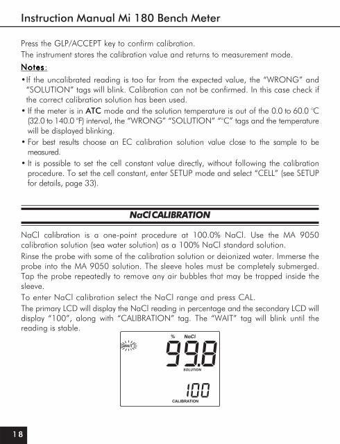
NaCl CALIBRATION
NaCl calibration is a one-point procedure at 100.0% NaCl. Use the MA 9050calibration solution (sea water solution) as a 100% NaCl standard solution.Rinse the probe with some of the calibration solution or deionized water. Immerse theprobe into the MA 9050 solution. The sleeve holes must be completely submerged.Tap the probe repeatedly to remove any air bubbles that may be trapped inside thesleeve.To enter NaCl calibration select the NaCl range and press CAL.The primary LCD will display the NaCl reading in percentage and the secondary LCD willdisplay “100”, along with “CALIBRATION” tag. The “WAIT” tag will blink until thereading is stable.

www.milwaukeeinst.com
19
GOOD LABORATORY PRACTICE (GLP)
GLP is a set of functions that allows storage and retrieval of calibration data and electrode status.All data regarding pH, EC and NaCl calibration is stored for the user to review when necessary.
CALIBRATION ALARM TIME-OUTCALIBRATION ALARM TIME-OUTCALIBRATION ALARM TIME-OUTCALIBRATION ALARM TIME-OUTCALIBRATION ALARM TIME-OUT
For pH calibration, Mi 180 allows the user to set the number of days (1 to 14) before the nextrequired calibration. The default setting is OFF (disabled).
The instrument checks the time-out and if the time elapsed, the “CALIBRATION EXPIRED”message will blink as a reminder.
NoteNoteNoteNoteNote: If the instrument is not calibrated, the “CALIBRATION EXPIRED” message will bedisplayed even if the calibration time-out feature is disabled in SETUP menu.
When the reading is stable, the “READY” and “ACCEPT” tags will blink on the LCD.Press the GLP/ACCEPT key to confirm calibration. The instrument stores the calibrationvalue and returns to measurement mode.
NotesNotesNotesNotesNotes:
•If the reading is too far from the expected value, the “WRONG” and “SOLUTION”tags will blink. Calibration cannot be confirmed.
• If the temperature of the buffer is out of the 0.0 – 60.0 °C (32.0 – 140.0 °F)temperature interval, the “WRONG” “SOLUTION”, “°C” tags and temperature willbe displayed blinking.
• If a new EC calibration is performed, the NaCl calibration is automatically cleared.Thus, a new NaCl calibration is required.

Instruction Manual Mi 180 Bench Meter
2 02 02 02 02 0
LAST LAST LAST LAST LAST pppppH CALIBRATION DATAH CALIBRATION DATAH CALIBRATION DATAH CALIBRATION DATAH CALIBRATION DATA
pH calibration data is stored automatically after a successful calibration.To view the last pH calibration data, press the GLP/ACCEPT key while in pH measurement mode.The instrument will display the time (hh:mm:ss) of the last calibration.
Press the arrow keys and the instrument will display the next calibration parameter (pressing theUP key):
• The date (MM.DD.YYYY).
• The pH calibration slope value on the primary LCD and the offset on the secondary LCD.

www.milwaukeeinst.com
21
• The pH calibration buffers in calibrating order.
The first pH calibration buffer:
• The second pH calibration buffer:
• The third pH calibration buffer:
NotesNotesNotesNotesNotes:
•The “OLd” message displayed under the pH value means that this buffer was not usedduring last calibration. Press the SHIFT&MODE/SETUP keys if you want to see calibrationdate (or time if old calibration was performed in the same day with current calibration).
Instruction Manual Mi 180 Bench Meter
2 22 22 22 22 2
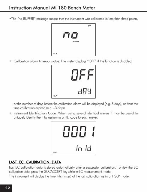
•The “no BUFFER” message means that the instrument was calibrated in less than three points.
• Calibration alarm time-out status. The meter displays “OFF” if the function is disabled,
or the number of days before the calibration alarm will be displayed (e.g. 5 days), or from thetime calibration expired (e.g. –3 days).
• Instrument Identification Code. When using several identical meters it may be useful touniquely identify them by assigning an ID code to each meter.
LAST LAST LAST LAST LAST ECECECECEC CALIBRATION DATA CALIBRATION DATA CALIBRATION DATA CALIBRATION DATA CALIBRATION DATALast EC calibration data is stored automatically after a successful calibration. To view the ECcalibration data, press the GLP/ACCEPT key while in EC measurement mode.The instrument will display the time (hh:mm:ss) of the last calibration as in pH GLP mode.

www.milwaukeeinst.com
23
Press the arrow UP key and the instrument will display the following calibration parameters:
• The date (MM.DD.YYYY) as in pH GLP mode.
• The EC calibration solution on the primary LCD and the cell constant on the secondary LCD.
• The EC calibration offset on the primary LCD.
• The reference temperature on the primary LCD.
• The temperature coefficient on the primary LCD, along with the temperature compensationmode.
• The instrument Identification Code as in pH GLP mode.

Instruction Manual Mi 180 Bench Meter
2 42 42 42 42 4
LAST LAST LAST LAST LAST NaClNaClNaClNaClNaCl CALIBRATION DATA CALIBRATION DATA CALIBRATION DATA CALIBRATION DATA CALIBRATION DATA
Last NaCl calibration data is stored automatically after a successful calibration. To view the NaClcalibration data, press the GLP/ACCEPT key when the instrument is in NaCl measurement mode.The instrument will display the time (hh:mm:ss) of the last calibration as in pH GLP mode.Press the UP and DOWN arrow keys to view the next logged calibration parameters(pressing the UP key):
• The date (MM.DD.YYYY) as in pH GLP mode.
• The cell constant.
• The salinity coefficient.
• The temperature coefficient on the primary LCD, along with the temperature compensationmode as in EC GLP mode.
• The reference temperature on the primary LCD as in pH GLP mode.• The instrument Identification Code as in pH GLP mode.
NotesNotesNotesNotesNotes:
• If a one-point pH calibration is performed after a two-point pH calibration, theinstrument will keep the old slope.
• Press the GLP/ACCEPT key at any moment and the instrument will return to measure-ment mode.

www.milwaukeeinst.com
25
LOGGING
Up to 50 readings can be stored into memory for each measurement range (pH, mV/Rel mV,EC, TDS and NaCl).
LOGGING THE CURRENT DATALOGGING THE CURRENT DATALOGGING THE CURRENT DATALOGGING THE CURRENT DATALOGGING THE CURRENT DATA
To store the current reading into memory press the LOG/CLR/MR key while in measurementmode.The instrument will display the current date (MM.DD) on the primary LCD and therecord number on the secondary LCD, along with “LOG” tag (see example below:record No. 25, dated July 28).
• If calibration has not been performed for the selected range, the instrument displays“no CAL” message blinking.
Instruction Manual Mi 180 Bench Meter
2 62 62 62 62 6
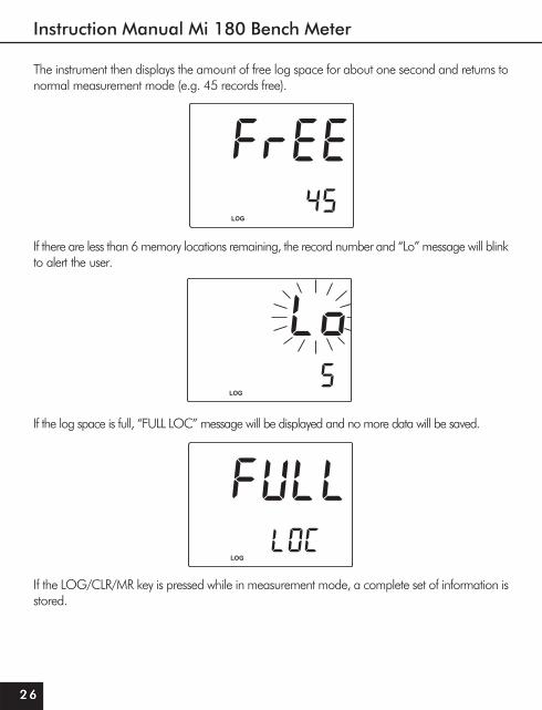
The instrument then displays the amount of free log space for about one second and returns tonormal measurement mode (e.g. 45 records free).
If there are less than 6 memory locations remaining, the record number and “Lo” message will blinkto alert the user.
If the log space is full, “FULL LOC” message will be displayed and no more data will be saved.
If the LOG/CLR/MR key is pressed while in measurement mode, a complete set of information isstored.

www.milwaukeeinst.com
27
VIEW LOGGED DATAVIEW LOGGED DATAVIEW LOGGED DATAVIEW LOGGED DATAVIEW LOGGED DATA
Press the SHIFT&LOG/CLR/MR keys to retrieve the information stored while in measurementmode.pH, mV/Rel mV RANGEIf no data is logged, the instrument displays “no rEC” message for the selected mode.
Otherwise, the instrument will display the pH pH pH pH pH or Rel mVRel mVRel mVRel mVRel mV value on the primary LCD and the laststored record number along with “LOG” tag.
Pressing the arrow keys, the instrument will display the same parameter but for a different record:
or
Instruction Manual Mi 180 Bench Meter
2 82 82 82 82 8
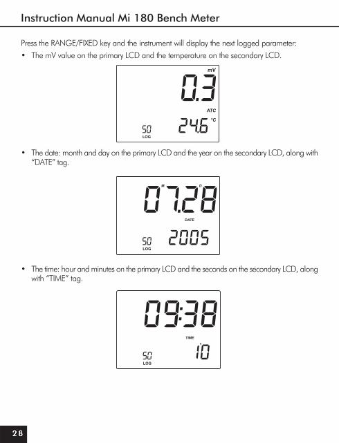
Press the RANGE/FIXED key and the instrument will display the next logged parameter:• The mV value on the primary LCD and the temperature on the secondary LCD.
• The date: month and day on the primary LCD and the year on the secondary LCD, along with“DATE” tag.
• The time: hour and minutes on the primary LCD and the seconds on the secondary LCD, alongwith “TIME” tag.

www.milwaukeeinst.com
29
• The slope on the primary LCD and the offset on the secondary LCD, along with “SLOPE”and “OFFSET” tags.
NoteNoteNoteNoteNote: If in mV/Rel mV RECALL mode, the instrument will display dashes for slope.• The “dEL” message on the primary LCD and the record number on the secondary LCD,
along with “ACCEPT” tag blinking.
NotesNotesNotesNotesNotes:
•If one of the arrow keys is pressed while “dEL” message is displayed, the next/previous recordnumber will be selected.
•If the SHIFT & MODE/SETUP key is pressed, the secondary LCD will toggle between therecord number and “ALL” message.

Instruction Manual Mi 180 Bench Meter
3 03 03 03 03 0
•Press the GLP/ACCEPT key to delete the selected or all records.•If “dEL ALL” option was selected, all records for the selected range are deleted and the
instrument returns to measurement mode.•After deleting a record, the “nuLL” message is displayed on the LCD for the selected record.
EC RANGEIf no data is logged, the instrument displays “no rEC” message for the selected mode.
Otherwise, the instrument will display the ECECECECEC, TDSTDSTDSTDSTDS or NaClNaClNaClNaClNaCl value on the primary LCD and thelast stored record number along with “LOG” tag.
Pressing the arrow keys, the instrument will display the same parameter but for a different record:
or or

www.milwaukeeinst.com
31
Press the RANGE/FIXED key and the instrument will display the next logged parameter:• The conductivity value on the primary LCD and the cell constant on the secondary LCD.
• The date as described in pH range.• The time as described in pH range.
• For EC mode: the offset on the primary LCD.
or• For TDS mode: the TDS factor.
Instruction Manual Mi 180 Bench Meter
3 23 23 23 23 2
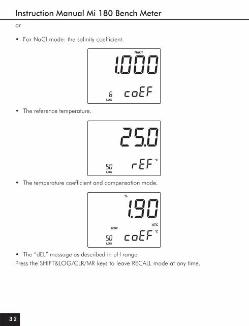
• For NaCl mode: the salinity coefficient.
• The reference temperature.
• The temperature coefficient and compensation mode.
• The “dEL” message as described in pH range.Press the SHIFT&LOG/CLR/MR keys to leave RECALL mode at any time.
or

www.milwaukeeinst.com
33
SETUP
Setup mode allows viewing and modifying the following parameters:
• Calibration Alarm Time-Out (pH range only)
• Buffer Display (pH range only)
• Cell Constant (EC range only)
• TDS Factor (EC range only)
• Temperature Coefficient (EC range only)
• Reference Temperature (EC range only)
• Current Time (hh:mm)
• Current Date (MM.DD.YYYY)
• Beep Status
• Baud Rate (serial communication)
• Instrument ID
• Temperature UnitTo enter SETUP mode, press the SHIFT&MODE/SETUP keys while in normal measurementmode.
Select the desired setup parameter using the UP and DOWN arrow keys.
Press the CAL key if you want to change the item value. The selected item (e.g. hour) will startblinking.
Press the arrow keys to change the blinking value.

Instruction Manual Mi 180 Bench Meter
3 43 43 43 43 4
If there is another item to be set (e.g. minutes), press the RANGE/FIXED key, and that item will startblinking.
Press the arrow keys to change the blinking value.Press the GLP/ACCEPT key to accept the value or the CAL key to escape.Press the arrow keys to select the next/previous parameter.Press the SHIFT & MODE/SETUP key to exit SETUP menu at any time.The following table lists the SETUP parameters, their valid values range and the factory settings(default):
NoteNoteNoteNoteNote: If “dISP” option is ON, the tags corresponding to the calibrated buffers are displayed onthe LCD while in pH measurement mode.
Item Description Valid values DefaultOFF dAY Alarm Time Out OFF or 1 to 14 days OFFdISP Display Cal Buffers ON/OFF ONCELL Cell Constant 0.500 to 1.700 1.000tdS TDS Factor 0.40 to 0.80 0.50tc Temperature Coefficient 0.00 to 6.00%/°C 1.90rEF Reference Temperature 20.0 or 25.0 °C 25.0TIME Time (hh:mm) 00:00 to 23:59 00:00DATE Date (MM.DD.YYYY) 01.01.2000-12.31.2099 01.01.2005bEEP Beep Status ON/OFF OFFbAud Baud Rate 600; 1200; 2400; 4800;9600 2400In Id Instrument ID 0000 to 9999 0000tEMP Temperature Unit °C or °F °C

www.milwaukeeinst.com
35
mV CALIBRATION (for technical personnel only)
The Mi Mi 180Mi 180Mi 180Mi 180180 is factory calibrated for mV.Martini’s ORP electrodes are interchangeable and no mV calibration is needed when they are replaced.If the mV measurements are inaccurate, mV recalibration should be performed.For an accurate recalibration, contact your dealer or the nearest Milwaukee Customer Service Center, or follow the instructions below.A two or three-point calibration can be performed at 0.0 mV, 600 mV and 1800 mV.
• Attach to the BNC connector a mV simulator with an accuracy of ±0.1 mV.
• With the instrument off, press and hold the CAL & SHIFT keys, then power on the instrument. The“CALIBRATION” tag will appear, and the secondary LCD will show 0.0 mV.
• Set 0.0 mV on the simulator.
• When the reading is stable and close to the selected calibration point, the “READY” and“ACCEPT” tags will blink.
• Press the GLP/ACCEPT key to accept the calibration point. The secondary LCD will display600 mV.
• Set 600 mV on the simulator.
• When the reading is stable and close to the selected calibration point, the “READY” and“ACCEPT” tags will blink.
• Press the GLP/ACCEPT key to accept the calibration point. The secondary LCD will display1800 mV.
• Set 1800 mV on the simulator.
• When the reading is stable and close to the selected calibration point, the “READY” and“ACCEPT” tags will blink.
• Press the GLP/ACCEPT key to accept the calibration point. The instrument returns tomeasurement mode.
NotesNotesNotesNotesNotes:
•If the reading is not close to the selected calibration point, “WRONG” tag will blink. Verifycalibration condition or contact your vendor if you cannot calibrate.
•To exit the calibration mode press the CAL key in any moment and the instrument will return tomeasurement mode. If you exit calibration after 600 mV is confirmed, the 600 mV range iscalibrated and calibration parameters are memorized.

Instruction Manual Mi 180 Bench Meter
3 63 63 63 63 6
TEMPERATURE CALIBRATION (for technical personnel only)
The Mi Mi 180Mi 180Mi 180Mi 180180 is factory calibrated for temperature.Martini’s temperature probes are interchangeable and no temperature calibration is needed when they are replaced.If the temperature measurements are inaccurate, temperature recalibration should be performed on both ranges (pH and EC).For an accurate recalibration, contact your dealer or the nearest Milwaukee Customer Service Center, or follow the instructions bellow.• Prepare a vessel containing ice and water and another one containing hot water
(at 50 °C). Place insulation material around the vessels to minimize temperature changes.• Use a calibrated thermometer with a resolution of 0.1°C.
• With the instrument off, press and hold the GLP/ACCEPT & LOG/CLR/MR keys (pH range)or CAL & LOG/CLR/MR keys (EC range), then power on the instrument. The “CALIBRA-TION” tag will appear and the secondary LCD will show 0.0 °C.
• Immerse the temperature probe in the vessel with ice and water as near as possible to thereference thermometer. Allow a few seconds for the probe to stabilize.
• Use the UP and DOWN arrow keys to set the reading on the secondary LCD to the onemeasured by the reference thermometer. When the reading is stable and close to theselected calibration point, the “READY” and “ACCEPT” tags will blink.
• Press the GLP/ACCEPT key to accept the calibration point. The secondary LCD will show50.0 °C.
• Immerse the temperature probe in the second vessel as near as possible to the referencethermometer. Allow a few seconds for the probe to stabilize.
• Use the UP and DOWN arrow keys to set the reading on the secondary LCD to that of thehot water.
• When the reading is stable and close to the selected calibration point, the “READY” and“ACCEPT” tags will blink.
• Press the GLP/ACCEPT key to accept the calibration point. The instrument returns tomeasurement mode.
NoteNoteNoteNoteNote: If the reading is not close to the selected calibration point, “WRONG” tag will blink.Change the temperature probe and restart calibration.

www.milwaukeeinst.com
37
EC SOLUTIONS TEMPERATURE DEPENDENCE
The conductivity of an aqueous solution is a measure of its ability to carry an electrical current by means of ionic motion.The conductivity invariably increases with increasing temperature.It is affected by the type and number of ions in the solutions and by the viscosity of the solution itself. Both parameters are temperature dependent. The dependency of con-ductivity on temperature is expressed as a relative change per Celsius degrees at a particular temperature, commonly as %/°C.The following table lists the temperature dependence of Milwaukee EC calibration solutions.
ºC ºF 0609AM)mc/Sμ(
1609AM)mc/Sμ(
3609AM)mc/Sμ(
4609AM)mc/Sμ(
5609AM)mc/Sμ(
9609AM)mc/Sμ(
05015161718191021222324252627282920313
0.230.140.050.958.066.264.462.660.868.966.174.372.570.778.876.084.282.480.688.78
0517022803390840102701059010911103411076110191105121093210462108821031310733102631078310214107341
677698020174113711991152211521872150312331953168313141044176414941125184515751
4656768607173747678797182848687898092949
0038400535006950045600276005860089600317004270004700257005670038700008003180003800948003680028800009
00456001470023800529004490036900289002001001201000401009501009701008901008111008311007511007711007911008121009321
06720813516336045514542473349244325471641174508420940005690509156825383597455755

Instruction Manual Mi 180 Bench Meter
3 83 83 83 83 8
PC INTERFACE
Data transmission from the instrument to the PC can be done with the Mi5200 Windows®
compatible software, when using the RS232 or USB serial interface. Mi Mi5200 also offers graphing and on-line help feature.Data can be exported to the most popular spreadsheet programs for further analysis.To connect the instrument to a PC through the RS232 port, use the Milwaukee MA9350 cable connector.To connect the instrument to a PC through the USB port, use a standard USB cable. Make sure that your instrument is switched off and plug one connector of the cable to the instrument RS232/USB connector and the other to the serial port of your PC.
NotesNotesNotesNotesNotes:
•Other cables than MAMAMAMAMA 93509350935093509350 may use a different configuration. In this case, communicationbetween instrument and PC may not be possible.
•Keep only one cable connected (RS232 or USB) during PC communication to avoidpossible errors.
•If you are not using Mi5200 software, please see the following instructions.
SENDING COMMANDS FROM PCSENDING COMMANDS FROM PCSENDING COMMANDS FROM PCSENDING COMMANDS FROM PCSENDING COMMANDS FROM PC
It is also possible to remotely control the instrument with any terminal program. Use MA 9350MA 9350MA 9350MA 9350MA 9350cable to connect the instrument to a PC, start the terminal program and set the communica-tion options as follows: 8, N, 1, no flow control.
COMMAND TYPESCOMMAND TYPESCOMMAND TYPESCOMMAND TYPESCOMMAND TYPESTo send a command to the instrument follow the next scheme:
<*> <command> <CR>where: <*> is the command prefix.
<command> is the command code.
NoteNoteNoteNoteNote: Either small or capital letters can be used.
UNIT CHANGE COMMANDUNIT CHANGE COMMANDUNIT CHANGE COMMANDUNIT CHANGE COMMANDUNIT CHANGE COMMAND
CHU xxCHU xxCHU xxCHU xxCHU xx Change the instrument unit according with the parameter value (xx):• xx=00 pH range/0.001 resolution• xx=01 pH range/0.01 resolution• xx=03 mV range• xx=04 Rel mV range
www.milwaukeeinst.com
39
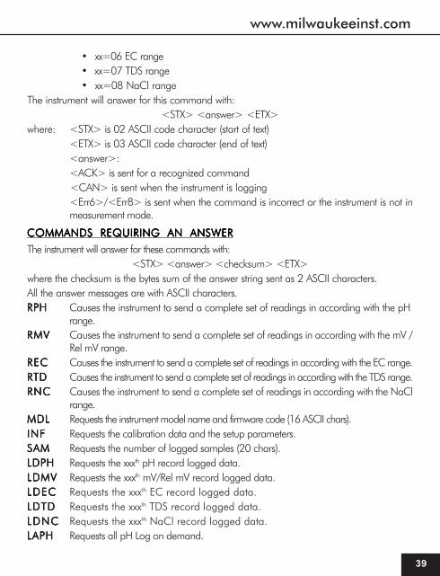
• xx=06 EC range• xx=07 TDS range• xx=08 NaCl range
The instrument will answer for this command with:<STX> <answer> <ETX>
where: <STX> is 02 ASCII code character (start of text)<ETX> is 03 ASCII code character (end of text)<answer>:<ACK> is sent for a recognized command<CAN> is sent when the instrument is logging<Err6>/<Err8> is sent when the command is incorrect or the instrument is not inmeasurement mode.
COMMANDS REQUIRING AN ANSWERCOMMANDS REQUIRING AN ANSWERCOMMANDS REQUIRING AN ANSWERCOMMANDS REQUIRING AN ANSWERCOMMANDS REQUIRING AN ANSWER
The instrument will answer for these commands with:<STX> <answer> <checksum> <ETX>
where the checksum is the bytes sum of the answer string sent as 2 ASCII characters.All the answer messages are with ASCII characters.RPHRPHRPHRPHRPH Causes the instrument to send a complete set of readings in according with the pH
range.RMVRMVRMVRMVRMV Causes the instrument to send a complete set of readings in according with the mV /
Rel mV range.RECRECRECRECREC Causes the instrument to send a complete set of readings in according with the EC range.RTDRTDRTDRTDRTD Causes the instrument to send a complete set of readings in according with the TDS range.RNCRNCRNCRNCRNC Causes the instrument to send a complete set of readings in according with the NaCl
range.MDLMDLMDLMDLMDL Requests the instrument model name and firmware code (16 ASCII chars).INFINFINFINFINF Requests the calibration data and the setup parameters.SAMSAMSAMSAMSAM Requests the number of logged samples (20 chars).LDPHLDPHLDPHLDPHLDPH Requests the xxxth pH record logged data.LDMVLDMVLDMVLDMVLDMV Requests the xxxth mV/Rel mV record logged data.LDECLDECLDECLDECLDEC Requests the xxxth EC record logged data.LDTDLDTDLDTDLDTDLDTD Requests the xxxth TDS record logged data.LDNCLDNCLDNCLDNCLDNC Requests the xxxth NaCl record logged data.LAPHLAPHLAPHLAPHLAPH Requests all pH Log on demand.

Instruction Manual Mi 180 Bench Meter
4 04 04 04 04 0
ELECTRODE CONDITIONING & MAINTENANCE
PREPARATION PROCEDUREPREPARATION PROCEDUREPREPARATION PROCEDUREPREPARATION PROCEDUREPREPARATION PROCEDURERemove the electrode protective cap.DO NOT BE ALARMED IF ANY SALT DEPOSITS ARE PRESENT. This is normal withelectrodes and they will disappear when rinsed with water.During transport tiny bubbles of air may have formed inside the glass bulb. The electrodecannot function properly under these conditions. These bubbles can be removed by “shakingdown” the electrode as you would do with a glass thermometer.If the bulb and/or junction are dry, soak the electrode in MA 9015MA 9015MA 9015MA 9015MA 9015 storage solution forat least one hour.For refillable electrodes, if the refill solution (electrolyte) is more than 2½ cm (1”) belowthe fill hole, add the appropriate electrolyte solution.
MEASUREMENTMEASUREMENTMEASUREMENTMEASUREMENTMEASUREMENT
Rinse the electrode tip with distilled water, immerse it (4 cm / 1½") into the sample and stirgently for a few seconds.For a faster response and to avoid cross contamination of the samples, rinse the electrodetip with the solution to be tested before taking any measurements.
STORAGE PROCEDURESTORAGE PROCEDURESTORAGE PROCEDURESTORAGE PROCEDURESTORAGE PROCEDURE
To minimize clogging and ensure a quick response time, the glass bulb and the junctionshould always be kept moist.When not in use, store it with a few drops of MMMMMAAAAA 90159015901590159015 storage solution in the protective cap.NEVER STORE THE ELECTRODE IN DISTILLED OR DEIONIZED WATER.
LAMVLAMVLAMVLAMVLAMV Requests all mV/Rel mV Log on demand.LAECLAECLAECLAECLAEC Requests all EC Log on demand.LATDLATDLATDLATDLATD Requests all TDS Log on demand.LANCLANCLANCLANCLANC Requests all NaCl Log on demand.
NotesNotesNotesNotesNotes:•“Err8” is sent if the instrument is not in measurement mode.•“Err6” is sent if the requested range is not available.•“Err4” is sent if the requested set parameter is not available.•“Err3” is sent if the Log on demand is empty.•Invalid commands will be ignored.

www.milwaukeeinst.com
41
PERIODIC MAINTENANCEPERIODIC MAINTENANCEPERIODIC MAINTENANCEPERIODIC MAINTENANCEPERIODIC MAINTENANCE
Inspect electrode and cable. The cable used for the connection to the instrument mustbe intact and there must be no points of broken insulation on the cable or cracks on theelectrode stem or bulb. If any scratches or cracks are present, replace the electrode.Rinse off any salt deposits with water.Connectors must be perfectly clean and dry.
For refillable electrodes:Refill the electrode with fresh electrolyte (see the electrode’s specifications to select thecorrect refilling solution). Allow the electrode to stand upright for 1 hour. Follow the StorageProcedure above.
pH CLEANING PROCEDUREpH CLEANING PROCEDUREpH CLEANING PROCEDUREpH CLEANING PROCEDUREpH CLEANING PROCEDURE
• General Soak in MAMAMAMAMA 90169016901690169016 General Cleaning Solution for approx. ½ hour.
IMPORTANT: After performing any of the cleaning procedures, rinse the electrode thoroughlywith distilled water and soak it in MMMMMAAAAA 90159015901590159015 storage solution for at least 1 hour before takingmeasurements.
EC PROBE MAINTENANCEEC PROBE MAINTENANCEEC PROBE MAINTENANCEEC PROBE MAINTENANCEEC PROBE MAINTENANCE
Rinse the probe with clean water after measurements. If a more thorough cleaning isrequired, remove the probe sleeve and clean the probe with a cloth or a nonabrasivedetergent. Make sure to reinsert the sleeve onto the probe properly and in the rightdirection. After cleaning the probe, recalibrate the instrument.Take great care while handling the probe.

Instruction Manual Mi 180 Bench Meter
4 24 24 24 24 2
TROUBLESHOOTING
SMOTPMYS MELBORP NOITULOS
.tfirdevissecxe/esnoperwolS .edortceleHpytriD nipitedortceleehtkaoSdnasetunim03rof6109AM
gninaelCehtwollofneht.erudecorP
dnapusetautculfgnidaeR.)esion(nwod
.noitcnuJytrid/deggolCelballifer(leveletylortcelewoL
.)ylnosedortceleylreporptoneveelseborpCE
edisniselbbubria;detresni.eveels
htiwllifeR.edortceleehtnaelC2109AMetylortcelehserf
.)ylnosedortceleelballifer(ehtpaT.eveelsehttresnI
.selbbubriaevomeroteborp
llufgniknilbswohsyalpsiDeulavelacs
.egnarfotuognidaeR nihtiwsielpmasehtkcehC;egnarelbarusaem
dnaleveletylortcelekcehC.sutatsedortcelelareneg
.egnarfotuoelacsVm .noitcnujyrdroenarbmemyrD niedortceleehtkaoSrofnoitulosegarots5109AM
.setunim03tsaelta
ro"°C"gniknilbswohsyalpsiD.egnarHpnielihw"°F"
erutarepmetredrofotuO.eborp
erutarepmetehtecalpeR.eborp
htiwkrowtonseodreteM.eborperutarepmet
.eborperutarepmetnekorB erutarepmetehtecalpeR.eborp
roetarbilacotsliafreteM.sgnidaerytluafsevig
.edortceleHpnekorB edortceleehtecalpeR
.lCaNetarbilacotsliafreteM .noitarbilacCEtcerrocnI CEniretemehtetarbilaceR.egnar
.1ottnatsnocllecteS
syalpsidretemehtputratstAyltnenamrepsgatDCLlla
.dekcolbsisyekehtfoenO rodraobyekehtkcehCrelaedruoytcatnoc
taegassem"2rE,1rE,0rE".putrats
lanretnI .rorre Contact your dealer or any Milwaukee Instruments Service Center.
For your Safety don’t use or store the instrument in hazardous environments. To avoiddamages or burns, do not perform any measurement in microwave ovens.
www.milwaukeeinst.com
43
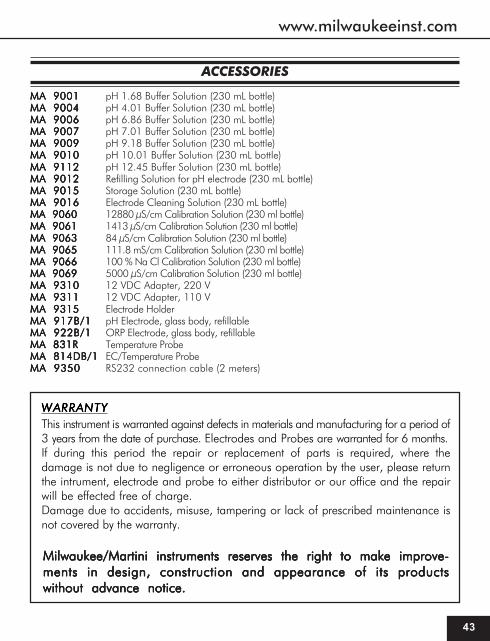
ACCESSORIES
MA 9001MA 9001MA 9001MA 9001MA 9001 pH 1.68 Buffer Solution (230 mL bottle)MA 9004MA 9004MA 9004MA 9004MA 9004 pH 4.01 Buffer Solution (230 mL bottle)MA 9006MA 9006MA 9006MA 9006MA 9006 pH 6.86 Buffer Solution (230 mL bottle)MA 9007MA 9007MA 9007MA 9007MA 9007 pH 7.01 Buffer Solution (230 mL bottle)MA 9009MA 9009MA 9009MA 9009MA 9009 pH 9.18 Buffer Solution (230 mL bottle)MA 9010MA 9010MA 9010MA 9010MA 9010 pH 10.01 Buffer Solution (230 mL bottle)MA 9112MA 9112MA 9112MA 9112MA 9112 pH 12.45 Buffer Solution (230 mL bottle)MA 9012MA 9012MA 9012MA 9012MA 9012 Refilling Solution for pH electrode (230 mL bottle)MA 9015MA 9015MA 9015MA 9015MA 9015 Storage Solution (230 mL bottle)MA 9016MA 9016MA 9016MA 9016MA 9016 Electrode Cleaning Solution (230 mL bottle)MA 9060MA 9060MA 9060MA 9060MA 9060 12880 μS/cm Calibration Solution (230 ml bottle)MA 9061MA 9061MA 9061MA 9061MA 9061 1413 μS/cm Calibration Solution (230 ml bottle)MA 9063MA 9063MA 9063MA 9063MA 9063 84 μS/cm Calibration Solution (230 ml bottle)MA 9065MA 9065MA 9065MA 9065MA 9065 111.8 mS/cm Calibration Solution (230 ml bottle)MA 9066MA 9066MA 9066MA 9066MA 9066 100 % Na Cl Calibration Solution (230 ml bottle)MA 9069MA 9069MA 9069MA 9069MA 9069 5000 μS/cm Calibration Solution (230 ml bottle)MA 9310MA 9310MA 9310MA 9310MA 9310 12 VDC Adapter, 220 VMA 9311MA 9311MA 9311MA 9311MA 9311 12 VDC Adapter, 110 VMA 9315MA 9315MA 9315MA 9315MA 9315 Electrode HolderMA 917B/1MA 917B/1MA 917B/1MA 917B/1MA 917B/1 pH Electrode, glass body, refillableMA 922B/1MA 922B/1MA 922B/1MA 922B/1MA 922B/1 ORP Electrode, glass body, refillableMA 831RMA 831RMA 831RMA 831RMA 831R Temperature ProbeMA 814DB/1MA 814DB/1MA 814DB/1MA 814DB/1MA 814DB/1 EC/Temperature ProbeMA 9350MA 9350MA 9350MA 9350MA 9350 RS232 connection cable (2 meters)
WARRANTYWARRANTYWARRANTYWARRANTYWARRANTYThis instrument is warranted against defects in materials and manufacturing for a period of3 years from the date of purchase. Electrodes and Probes are warranted for 6 months.If during this period the repair or replacement of parts is required, where thedamage is not due to negligence or erroneous operation by the user, please returnthe intrument, electrode and probe to either distributor or our office and the repairwill be effected free of charge.Damage due to accidents, misuse, tampering or lack of prescribed maintenance isnot covered by the warranty.
Milwaukee/Martini instruments reserves the right to make improve-Milwaukee/Martini instruments reserves the right to make improve-Milwaukee/Martini instruments reserves the right to make improve-Milwaukee/Martini instruments reserves the right to make improve-Milwaukee/Martini instruments reserves the right to make improve-ments in design, construction and appearance of its productsments in design, construction and appearance of its productsments in design, construction and appearance of its productsments in design, construction and appearance of its productsments in design, construction and appearance of its productswithout advance notice.without advance notice.without advance notice.without advance notice.without advance notice.

THANK YOU FOR CHOOSING
Sales and Technical Service Contacts:
Milwaukee Electronics Kft.Alsókikötő sor 11.
6726, Szeged, HungaryTel: +36-62-428-050Fax: +36-62-428-051
e-mail: [email protected]
Milwaukee Instruments, Inc.2950 Business Park Drive Rocky Mount, NC
27804 USATel: +1 252 443 3630Fax: +1 252 443 1937
e-mail: [email protected]
www.milwaukeeinst.com
MANMI180 06/08