Instruction Manual - alfalaval.us · ATEX marking ... article and serial numbers are laser engraved...
58
4107-0143 Covering: Standard, Hastelloy Q-doc: Equipment Doc (3.1 Inspection Certificate - EN 10204) Q-doc+FAT-SAT: Qualification Documentation incl. FAT and SAT) Improved surface finish (0.5 μm Ra internal/external media contact parts) Machines delivered with ATEX Certification in accordance with Directive 2014/34/EU. TE91A793-EN12. First published: 04-2009 ESE01829-EN12 2016-07 Original manual Instruction Manual Alfa Laval Toftejorg™ SaniJet 20 Air Driven
-
Upload
phungnguyet -
Category
Documents
-
view
215 -
download
3
Transcript of Instruction Manual - alfalaval.us · ATEX marking ... article and serial numbers are laser engraved...

4107-0143
Covering: Standard, HastelloyQ-doc: Equipment Doc (3.1 Inspection Certificate - EN 10204)Q-doc+FAT-SAT: Qualification Documentation incl. FAT and SAT)Improved surface finish (0.5 µm Ra internal/external media contact parts)Machines delivered with ATEX Certification in accordance with Directive 2014/34/EU.TE91A793-EN12. First published: 04-2009
ESE01829-EN12 2016-07
Original manual
Instruction Manual
Alfa Laval Toftejorg™ SaniJet 20 Air Driven


Table of contents
The information herein is correct at the time of issue but may be subject to change without prior notice
1. EC/EU Declaration of Conformity .. . . . . . . . . . . . . . . . . . . . . . . . . . . . . . . . . . . . . . . . . . . . . . . . . . . . . . . . . . . . . . . . . 5
2. Safety ... . . . . . . . . . . . . . . . . . . . . . . . . . . . . . . . . . . . . . . . . . . . . . . . . . . . . . . . . . . . . . . . . . . . . . . . . . . . . . . . . . . . . . . . . . . . . . . . . . 62.1. Important information .. . . . . . . . . . . . . . . . . . . . . . . . . . . . . . . . . . . . . . . . . . . . . . . . . . . . . . . . . . . . . . . . . . . . . . . . . . . . 62.2. Warning signs .. .. . . . . . . . . . . . . . . . . . . . . . . . . . . . . . . . . . . . . . . . . . . . . . . . . . . . . . . . . . . . . . . . . . . . . . . . . . . . . . . . . . 6
3. Introduction .. . . . . . . . . . . . . . . . . . . . . . . . . . . . . . . . . . . . . . . . . . . . . . . . . . . . . . . . . . . . . . . . . . . . . . . . . . . . . . . . . . . . . . . . . . . 73.1. Introduction .. . . . . . . . . . . . . . . . . . . . . . . . . . . . . . . . . . . . . . . . . . . . . . . . . . . . . . . . . . . . . . . . . . . . . . . . . . . . . . . . . . . . . . . 73.2. Intended use .. . .. . . . . . . . . . . . . . . . . . . . . . . . . . . . . . . . . . . . . . . . . . . . . . . . . . . . . . . . . . . . . . . . . . . . . . . . . . . . . . . . . . 83.3. Patents and trademarks ... . . . . . . . . . . . . . . . . . . . . . . . . . . . . . . . . . . . . . . . . . . . . . . . . . . . . . . . . . . . . . . . . . . . . . . 83.4. Reserved rights for design changes .. . . . . . . . . . . . . . . . . . . . . . . . . . . . . . . . . . . . . . . . . . . . . . . . . . . . . . . . . . . 83.5. ATEX marking .. .. . . . . . . . . . . . . . . . . . . . . . . . . . . . . . . . . . . . . . . . . . . . . . . . . . . . . . . . . . . . . . . . . . . . . . . . . . . . . . . . . . 9
4. Installation .. . . . . . . . . . . . . . . . . . . . . . . . . . . . . . . . . . . . . . . . . . . . . . . . . . . . . . . . . . . . . . . . . . . . . . . . . . . . . . . . . . . . . . . . . . . . . 104.1. General Description .. .. . . . . . . . . . . . . . . . . . . . . . . . . . . . . . . . . . . . . . . . . . . . . . . . . . . . . . . . . . . . . . . . . . . . . . . . . . . . 104.2. Quality system ... . . . . . . . . . . . . . . . . . . . . . . . . . . . . . . . . . . . . . . . . . . . . . . . . . . . . . . . . . . . . . . . . . . . . . . . . . . . . . . . . . 104.3. Functionality . . . . . . . . . . . . . . . . . . . . . . . . . . . . . . . . . . . . . . . . . . . . . . . . . . . . . . . . . . . . . . . . . . . . . . . . . . . . . . . . . . . . . . . 114.4. Installation of Air Motor . . . . . . . . . . . . . . . . . . . . . . . . . . . . . . . . . . . . . . . . . . . . . . . . . . . . . . . . . . . . . . . . . . . . . . . . . . . 144.5. General Safety and Installation Instructions .. .. . . . . . . . . . . . . . . . . . . . . . . . . . . . . . . . . . . . . . . . . . . . . . . . . 164.6. Special Conditions for Safe Use in accordance with ATEX Certification .. .. . . . . . . . . . . . . . . . . 17
5. Operation ... . . . . . . . . . . . . . . . . . . . . . . . . . . . . . . . . . . . . . . . . . . . . . . . . . . . . . . . . . . . . . . . . . . . . . . . . . . . . . . . . . . . . . . . . . . . . 195.1. Normal operation .. . . . . . . . . . . . . . . . . . . . . . . . . . . . . . . . . . . . . . . . . . . . . . . . . . . . . . . . . . . . . . . . . . . . . . . . . . . . . . . . 195.3. Normal Operation of Air Motor .. . . . . . . . . . . . . . . . . . . . . . . . . . . . . . . . . . . . . . . . . . . . . . . . . . . . . . . . . . . . . . . . . 205.4. Safety Precautions .. . .. . . . . . . . . . . . . . . . . . . . . . . . . . . . . . . . . . . . . . . . . . . . . . . . . . . . . . . . . . . . . . . . . . . . . . . . . . . . 21
6. Maintenance .. . .. . . . . . . . . . . . . . . . . . . . . . . . . . . . . . . . . . . . . . . . . . . . . . . . . . . . . . . . . . . . . . . . . . . . . . . . . . . . . . . . . . . . . . . 226.1. Preventive Maintenance .. .. . . . . . . . . . . . . . . . . . . . . . . . . . . . . . . . . . . . . . . . . . . . . . . . . . . . . . . . . . . . . . . . . . . . . . . 226.2. Reserved rights for design changes of Alfa Laval equipment used in validated processes 226.3. Preventive Maintenance of Air Motor . . . . . . . . . . . . . . . . . . . . . . . . . . . . . . . . . . . . . . . . . . . . . . . . . . . . . . . . . . . 236.4. Service and Repair of ATEX certified Machines .. . .. . . . . . . . . . . . . . . . . . . . . . . . . . . . . . . . . . . . . . . . . . . . 246.5. Service and repair of machines ordered with Q-doc and with Q-doc + FAT-SAT .. . .. . . . . . 256.6. Every 300 Working Hours .. . . . . . . . . . . . . . . . . . . . . . . . . . . . . . . . . . . . . . . . . . . . . . . . . . . . . . . . . . . . . . . . . . . . . . . 266.7. Cleaner Head Unit - dismantling and reassembling .. . . . . . . . . . . . . . . . . . . . . . . . . . . . . . . . . . . . . . . . . . 276.8. Base Unit - Dismantling and Reassembling .. .. . . . . . . . . . . . . . . . . . . . . . . . . . . . . . . . . . . . . . . . . . . . . . . . . 286.9. Air Motor Drive Unit - dismantling and reassemebling ... . . . . . . . . . . . . . . . . . . . . . . . . . . . . . . . . . . . . . 296.10.Rotacheck System .... . . . . . . . . . . . . . . . . . . . . . . . . . . . . . . . . . . . . . . . . . . . . . . . . . . . . . . . . . . . . . . . . . . . . . . . . . . . 31
7. Trouble Shooting Guide ... . . . . . . . . . . . . . . . . . . . . . . . . . . . . . . . . . . . . . . . . . . . . . . . . . . . . . . . . . . . . . . . . . . . . . . . . . . . 32
8. Technical Data ... . . . . . . . . . . . . . . . . . . . . . . . . . . . . . . . . . . . . . . . . . . . . . . . . . . . . . . . . . . . . . . . . . . . . . . . . . . . . . . . . . . . . . . 34
9. Product Programme ... . . . . . . . . . . . . . . . . . . . . . . . . . . . . . . . . . . . . . . . . . . . . . . . . . . . . . . . . . . . . . . . . . . . . . . . . . . . . . . . 389.1. Standard configurations .. .. . . . . . . . . . . . . . . . . . . . . . . . . . . . . . . . . . . . . . . . . . . . . . . . . . . . . . . . . . . . . . . . . . . . . . . 389.2. Available add-ons .. . . . . . . . . . . . . . . . . . . . . . . . . . . . . . . . . . . . . . . . . . . . . . . . . . . . . . . . . . . . . . . . . . . . . . . . . . . . . . . . 409.3. Available add-ons for spare parts . . .. . . . . . . . . . . . . . . . . . . . . . . . . . . . . . . . . . . . . . . . . . . . . . . . . . . . . . . . . . . . 419.4. Accessories .. . . . . . . . . . . . . . . . . . . . . . . . . . . . . . . . . . . . . . . . . . . . . . . . . . . . . . . . . . . . . . . . . . . . . . . . . . . . . . . . . . . . . . 42
10. Parts Drawing and Lists, Service Kits and Tools .. . .. . . . . . . . . . . . . . . . . . . . . . . . . . . . . . . . . . . . . . . . . . . . 4310.1.Part List Drawing .. . . . . . . . . . . . . . . . . . . . . . . . . . . . . . . . . . . . . . . . . . . . . . . . . . . . . . . . . . . . . . . . . . . . . . . . . . . . . . . . . 4310.2.Part list - Alfa Laval Toftejorg SaniJet 20 Air Driven .. . . . . . . . . . . . . . . . . . . . . . . . . . . . . . . . . . . . . . . . . . 4410.3.Part list - Alfa Laval Toftejorg SaniJet 20 Air Driven improved surface finish .. . . . . . . . . . . . . . . 4610.4.Part list - Alfa Laval Toftejorg SaniJet 20 Air Driven Hastelloy . . . . . . . . . . . . . . . . . . . . . . . . . . . . . . . . 48
3

Table of contents
The information herein is correct at the time of issue but may be subject to change without prior notice
10.5.Part List - Alfa Laval Toftejorg SaniJet 20 Air Driven Hastelloy improved surface finish .. . . 5010.6.Service Kits . . .. . . . . . . . . . . . . . . . . . . . . . . . . . . . . . . . . . . . . . . . . . . . . . . . . . . . . . . . . . . . . . . . . . . . . . . . . . . . . . . . . . . . . 5210.7.Tools . . . .. . . . . . . . . . . . . . . . . . . . . . . . . . . . . . . . . . . . . . . . . . . . . . . . . . . . . . . . . . . . . . . . . . . . . . . . . . . . . . . . . . . . . . . . . . . 53
11. General information .. .. . . . . . . . . . . . . . . . . . . . . . . . . . . . . . . . . . . . . . . . . . . . . . . . . . . . . . . . . . . . . . . . . . . . . . . . . . . . . . . . 5411.1.Service and Repair . . . . . . . . . . . . . . . . . . . . . . . . . . . . . . . . . . . . . . . . . . . . . . . . . . . . . . . . . . . . . . . . . . . . . . . . . . . . . . . 5411.2.How to order Spare Parts . . .. . . . . . . . . . . . . . . . . . . . . . . . . . . . . . . . . . . . . . . . . . . . . . . . . . . . . . . . . . . . . . . . . . . . . 5411.3.How to contact Alfa Laval Kolding A/S .. . .. . . . . . . . . . . . . . . . . . . . . . . . . . . . . . . . . . . . . . . . . . . . . . . . . . . . . 54
12. Miscellaneous .. . . .. . . . . . . . . . . . . . . . . . . . . . . . . . . . . . . . . . . . . . . . . . . . . . . . . . . . . . . . . . . . . . . . . . . . . . . . . . . . . . . . . . . . . 5512.1.Declarations of Conformity per EN 10204 2.2 ... . . . . . . . . . . . . . . . . . . . . . . . . . . . . . . . . . . . . . . . . . . . . . . 5512.2.ATEX - Specific conditions of use .. . . . . . . . . . . . . . . . . . . . . . . . . . . . . . . . . . . . . . . . . . . . . . . . . . . . . . . . . . . . . . 57
4

1 EC/EU Declaration of Conformity
The Designated Company
Alfa Laval Kolding A/SCompany Name
Albuen 31, DK-6000 Kolding, DenmarkAddress
+45 79 32 22 00Phone No.
hereby declare that
Tank Cleaning MachineDesignation
Alfa Laval Toftejorg SaniJet 20 Air DrivenTypeFrom serial number 2016-0001 to 2030-99999
is in conformity with the following directive with amendments:Machinery Directive 2006/42/ECDS/EN ISO 12100:2011The Pressure Directive 97/23/ECAccording to its own volume and the rated pressure range, the product is regarded an Article 3, paragraph 3 EquipmentFDA 21CFR§177Regulation (EC) 1935/2004Equipment Explosive Atmospheres (ATEX) Directive 2014/34/EU(Applicable for machine certified as category 1 and 2 component, see machine engraving)DS/EN 13463-1:2009, DS/EN 13463-5:2011, DS/EN ISO/IEC 80079-34:2011, Annex A, paragraph A.5.3 Rotating machinesSaniJet 20 A, Tank cleaning unitEC Type Examination Certificate no. Baseefa05ATEX0117XMarking: II 1 GD c T140°C
SGS Baseefa Ltd., Certification body number 1180, Rockhead Business Park, Staden Lane, Buxton, Derbyshire SK17 9RZ, United Kingdom
The technical construction file is retained at the above address
SaniJet 20 A, Air Motor UnitArchive no.: DTI-2013-1-0148AMarking: II 2 GD c IIC T4 Tamb -20°C to +40°C
Archived at Danish Technological Institute, Certification body number 0396, Gregersensvej, 2630 Taastrup, Denmark
The person authorised to compile the technical file is the signer of this document
Global Product Quality ManagerPumps, Valves, Fittings and Tank Equipment Lars Kruse Andersen
Title Name Signature
ATEX Responsible Engineer Denniz HøxbroeTitle Name Signature
Kolding 2016-05-01Place Date
(This Declaration of Conformity replaces Declaration of Conformity dated 2016-01-01)
5

2 Safety
Unsafe practices and other important information are emphasized in this manual.Warnings are emphasized by means of special signs.Always read the manual before using the tank cleaning machine!
2.1 Important information
WARNINGIndicates that special procedures must be followed to avoid serious personal injury.
CAUTIONIndicates that special procedures must be followed to avoid damage to the tank cleaning machine
NOTEIndicates important information to simplify or clarify procedures.
2.2 Warning signs
General warning:
6

3 Introduction
ESE01829
3.1 Introduction
This manual has been prepared as a guide for installation and for the persons who will be operating and maintaining your tankcleaning machine. The key to long life for your tank cleaning machine is a carefully planned system for preventive maintenance;you must appreciate that a tank cleaning machine which has a rough and dirty job to do will need more frequent attention thanone working under ideal conditions.
Note: Get the best and most economical performance from your tank cleaning machine. Insufficient preventive maintenancemeans poor performance, unscheduled stops, shorter lifetime and extra costs. Good preventive maintenance on the contrarymeans good performance, no unscheduled stops and superior total economy.
Should you require further assistance, our Technical Sales Support department and worldwide net of sales offices will bepleased to help you. Please quote the type, article and serial numbers with all of your enquiries; this helps us to help you. Thetype, article and serial numbers are laser engraved on the Base house of the tank cleaning machine.
4107-0035
Warning: Before installing the machine and setting it into operation carefully read the General Installation and SafetyInstructions (page 16) and the special conditions for safe use in accordance with ATEX Certification Directive2014/34/EU (page 17) and take all necessary precautions according to your application and local regulations.
NOTEThe illustrations and specifications contained in this manual were effective at the date of printing. However, as continuousimprovements are our policy, we reserve the right to alter or modify any unit specification on any product without prior notice orany obligation.
The English version of the instruction manual is the original manual. We make reservations in regard to possible mistranslations inlanguage versions of the instruction manual. In case of doubt, the English version of the instruction manual applies.
7

3 Introduction
ESE01829
3.2 Intended use
It is to be verified by the end-user:
- that the tank cleaning machine is in conformity with respect to tank, vessel or container size in which it will be used.- that the construction materials (both metallic and non-metallic) are compatibility with product, flushing media, cleaning
media, temperatures and pressure under the intended use.
3.3 Patents and trademarks
This Instruction Manual is published by Alfa Laval Kolding A/S without any warranty. Improvements and changes to thisInstruction Manual may at any time be made by Alfa Laval Kolding A/S without prior notice. Such changes will, however,be incorporated in new editions of this Instruction Manual.
Alfa Laval Kolding A/S. All rights reserved.
The Alfa Laval logotype is a trademark or a registered trademark of Alfa Laval Corporate AB. "Toftejorg" and “SaniJet” aretrademarks or registered trademarks of Alfa Laval Kolding A/S. The Toftejorg™ SaniJet 20 product has patents in the EPOmember states, in the US and in other countries. Other products or company names mentioned herein may be the trademarksof their respective owners. Any rights not expressly granted herein are reserved.
3.4 Reserved rights for design changes
Alfa Laval is continuously working on improving our equipment and services. In this improvement work Alfa Laval may forexample change the design and material in our equipment. A change in the design will not necessarily entail a change of thespecification and item no. for the equipment.
Alfa Laval reserves the right to change the design of Alfa Laval equipment without any notifications for improvements of ourdesign.
If Equipment from Alfa Laval is used in connection with, for example, a validated plant, and an order for replacements ismade, the design of the replacement may have been changed even if the specifications /item no. is the same as the existinginstalled and validated ones.
When ordering a replacement please contact Alfa Laval sales support in this matter before placing the order.
8

3 Introduction
ESE01829
3.5 ATEX marking
The Alfa Laval Toftejorg SaniJet 20A Cleaner unit is certified as category 1 component for installation in zone 0/20 (inside tank)in accordance to Directive 94/9/EC. The certification is carried out by the Certification body SGS Baseefa, who has issued thecertificate no. 1180 Baseefa 05ATEX0117X.
Marked: II 1 GD c T140°C
The Alfa Laval Toftejorg SaniJet 20A Air drive unit is certified as category 2 component for installation in zone 1/21 (outsidetank) in accordance to Directive 94/9/EC. The certification is carried out by Alfa Laval as a Own Assessment and archived atCertification body Teknologisk Institut. Registered as archive no.: DTI-2013-1-0148A.
Marked: II 2GD c IIC T4 Tamb -20°C to +40°C
Serial number explanationMachines supplied with or without standard documentation:
yyyy-xxxxx: serial numberyyyy: year
xxxxx: 5 digit sequential number
Important information: Also see “Maintenance” page 24regarding special conditions for repair of ATEX certifiedmachines.
A
4107-0036
A: For FAT-SAT machines with index no. -6x, the s/n must be yyy-FAT-SAT-xxx
Changes to the machine are not allowed without approval by the person responsible for the ATEX certification at Alfa LavalKolding A/S. If changes are made – or spare parts other than Alfa Laval original spare parts are used - the EC Type Examinationcertification (the ATEX Directive) is no longer valid.
9

4 Installation
ESE01829
4.1 General Description
The Alfa Laval Toftejorg SaniJet 20 is a tank cleaning machine intended for industrial use in closed tanks for processing storageand transportation. There is a broad range of application areas within pharmaceutical, food and chemical industries.
The Alfa Laval Toftejorg SaniJet 20 is a hygienic cleaning device of the rotary jet head type for permanent installation that providesa 360° indexed cleaning pattern. Provided it is installed in an upright position, the Alfa Laval Toftejorg SaniJet 20 is completelyself-cleaning and self-draining, and it has an integrated self-cleaning down pipe (patent pending). The drive mechanism is locatedoutside the tank or process equipment, leaving a minimum of parts to be submerged into the product. All product contactsurfaces are AISI 316/316L, duplex SAF 2205, Ti, Hastelloy C22/C276 stainless steel and USP Class VI and FDA approvedpolymer materials such as PEEK, EPDM, Viton and FFKM.
No threads or screws have been used in the product contact areas.
The cleaning device is lubricated by the cleaning media. No oil, grease or other lubricants are used.
The Alfa Laval Toftejorg SaniJet 20 is available in media driven or air motor driven versions. The air motor driven version isequipped with a magnetic clutch providing a leakage-proof transmission and provide an effective drive for low flow machinesin rough environments. The air motor has variable speed in order to adjust cleaning intensity. The media version is covered byInstruction Manual IM-TE91A792.
The Alfa Laval Toftejorg SaniJet 20 is designed for use in pharmaceutical, biotechnological, food and dairy processing applica-tions. Tanks and vessels between 0.5-30 m3 (130-8,000 US gallons). The design makes the Alfa Laval Toftejorg SaniJet 20especially well suited when processing high viscous, foaming or thixotropic products and in chemical processing applications,where product cross contamination is unacceptable and must be avoided.
For use in explosive hazard zones the air motor driven version can be used, provided it is installed according to safety instructionsin local regulations.
4.2 Quality system
The Alfa Laval Toftejorg SaniJet 20 is produced according to Alfa Laval Kolding’s ISO 9001 International Standard certifiedquality system. All parts are made from certified material and all non-metal parts are made from FDA and USP Class VIapproved materials.
10

4 Installation
ESE01829
4.3 Functionality
Alfa Laval Toftejorg SaniJet 20 consists of 3 main parts: The Drive unit with flow inlet and the Base housing placed outside thetank, and inside the tank: the Down pipe with the rotating Outer tube and the Cleaner unit.
The flow of the cleaning fluid passes from the inlet through the Base housing,through the Down pipe, into the Cleaner head and out through the Nozzles. TheOuter tube of the Down pipe is rotably suspended on a Stationary shaft with a Ballbearing inside the Outer tube. The Drive mechanism rotates the Outer tube withthe Cleaner unit around the vertical axis. Via a set of Bevel gears on the Stationaryshaft and the Cleaner head, the Cleaner head with the Nozzles is simultaneouslyrotated around the horizontal axis in a fixed relation thus moving the nozzles andthe jets 360° around in the tank making a pre-set indexed cleaning pattern.
The Alfa Laval Toftejorg SaniJet 20 utilises the patented “Golden Section” cleaning pattern. The distance between the tracksof the jets ensures an efficient removal of remaining product from the tank surface right from the beginning of the cleaningsequence, allowing for short cleaning time.
Example - 2 nozzle machine:
TD523451TD523452
TD523453
0.8 min. 2.3 min. 6 min.
The time needed to perform a proper cleaning depends on type of soilage, distance, cleaning procedure and agent. For sub-stances that are easily mobilised, i.e. are easy to remove, less than 1 min. could be sufficient while in cases of more heavy soilage(high viscous, sticky substances, etc.) a more dense pattern/longer time will be needed.
11

4 Installation
ESE01829
Machine with external motor drive
The machine is driven by a gear motor mounted on top of the Inlet housing. Via a Magnetic clutch the rotation of the gear motoris transmitted from the outside through a closed wall to the Output shaft placed inside the Inlet housing. The Output shaft is inmesh with the Down pipe and rotates the Down pipe in the same way as in the media driven version.
A: Gear MotorB: Cup-shaped closed wallC: Output shaft
A
B
C
*Note
4107-0037
*Note: Motor driven version with magnetic
clutch
The output shaft of the gear motor is equipped with a Rotor with permanent magnets. The rotor is placed inside the cavity in theMotor flange, made by the cup protruding into the liquid chamber in the Inlet housing. The cup is welded to the motor flange asa hermetic sealed closed wall between the liquid chamber and the outside. The magnetic field from the permanent magnets istransferred through the wall, to a ring with permanent magnets inside the Output shaft, which is placed around the cup on theinside the liquid chamber.
A: Motor flangeB: Rotor with magnetsC: Cup-shaped colosed wallD: Ring with magnets inside Output shaftA
B
C
D
4107-0038
The machine with Air motor is equipped with a flow regulator to make the speed adjustable between approx. 3 and 14 RPM.
12

4 Installation
ESE01829
Self-cleaningApart from the main flow flushing the inside of the Base housing and the Down pipe, and thereafter forming the jets through theNozzles, fluid is flushed through all internal cavities, through Bevel gear, Ball bearings and gabs between moving parts and isfinally also used for cleaning of the outside surfaces of the machine. From the gab between the Base housing and the rotatingDown pipe, a cleaning jet is directed against the Down pipe, thus loosening and removing product remains on the outside. Aliquid film flushing all around the tube further assists by continuously transporting away loosened product remains. The front ofthe Cleaner head is flushed by a liquid flow from the gab between the Cleaner head and the Retaining ring.
In order to ensure a proper self-cleaning, the machine must be installed in an approx. upright position and the inlet pressuremust be min. 3 bar. In the bottom of the Cleaner head, in the Retaining ring, the machine is equipped with a hole to ensureself-draining. This self-draining is only ensured, if the machine is installed in an upright position.
Cleaning Pattern, The Golden SectionThe patented Golden Section cleaning pattern (EP-Patent No.: 0495883. US-Patent No.: 5,279.675) is unique in building upthe pattern in an ultimate uniform way. The pattern starts very coarse and refines itself in a step-less way by laying out thetracks approximately in the middle between the two most distant tracks already made. This means that the jets always cleanthe areas containing most remaining product, and thereby remove as much deposit as possible in the shortest possible way.
In case a complete cleaning pattern is not required, it will be possible to reach the same cleaning level within half the time andby using half the amount of cleaning fluid compared to a traditional step-wise cleaning pattern. Furthermore, due to the uniformcleaning pattern, the cleaning can be stopped at any time, whereas with traditional non-uniform cleaning pattern this would notbe advantageous. However, after the complete cleaning pattern has been established, the difference between the GoldenSection and the traditional stepwise cleaning pattern is negligible.
Golden Section - Cleaning pattern Traditional - Cleaning pattern
TD523454 TD523455
13

4 Installation
ESE01829
4.4 Installation of Air Motor
Important informationRecommended inlet air pressure is not to exceed 6 bar (87) psi maximum. It is recommended to use an air filter and moisturetrap on inlet air supply to avoid contamination being fed into air motor.
General informationThe air motor is designed to be driven by compressed air and under no circumstances be driven with any other gases.Fluids, particles, solids or any substances mixed with air, particularly combustible substances likely to cause explosions,must not drive air motor.
Warning: Do not drive with flammable or explosive gases.
Warning: Air motor is designed for air only. Do not allow corrosive gases or particulate material to enter motor. Water vapor,oil-based contaminants, or other liquids must be filtered out.
Warning: Do not use a hammer or force coupling or drive pulley onto shaft when installing drive onto air motor. This causesend thrust that could damage air motor.
Note: Ambient temperature outside tank should not exceed +40°C (140°F)
InstallationInstall a moisture trap and filter in air line ahead of motor. For efficiency of output and control of speed, use air lines ofsame size or in next pipe size larger than intake port of motor. As inlet line a ø8/5.5 tube should be used (customer supply).As standard, the drive unit is fitted with a hose connector ø8 on the blow-out line. It is possible to lead the exhaust out of theroom with a hose and it is recommended in this context to use an adapter so that a ø12 tube or larger can be used for this. Itis also possible to attach a silencer on the exhaust, but in this respect it should be borne in mind that a possible oil mist maycontaminated surroundings in the room where it exhausted
14

4 Installation
ESE01829
LubricationThe pneumatic oil used for lubrication must have a self–ignition temperature above 260°C and have a viscosity between 22 and46 cst depending on the temperature of the motor operation (e.g. 40°C the viscosity of the oil shall be between 22 and 30 cst).
MODEC recommends that an automatic air line lubricator, be installed in air line just ahead of air motor. Lubricator should beadjusted to feed with 50mm³ of oil per m³ of air (1 drop = 15 mm³) (see table below).
At max power At max speedAir cons. (1/min) Lubrication (drops/min) Air cons. (1/min) Lubrication (drops/min)
290 1 360 1
Valve mini Kv Max air flow (1/min) Feeding pipe min. dia. (mm) Connection min. dia. (mm)20 1293 6 5
Lubrication is necessary for all internal moving parts. Excessive moisture in air line can cause rust formation in motor andmight also cause ice to form in muffler due to expansion of air through motor. Moisture problem can be corrected by installinga moisture separator in line and also by installing an after-cooler between compressor and air receiver.A lubricant filter (FRL) unit should be installed between upstream from the motor. Filtration should be 50 micron maximum.
Mounting
Warning:Beware of any exposed and/or moveable parts. Proper guards should be in place to prevent personaland/or property damage.
15

4 Installation
ESE01829
4.5 General Safety and Installation Instructions
The Alfa Laval Toftejorg SaniJet 20 is designed to be installed in a vertical upright position.
It is recommended to install a filter with mesh size 250 µm (0,0001") in the supply line in order to avoid particles, scale etc.from clogging inside the machine. It is essential to avoid fine solid particles, such as fine sand, in the cleaning fluid as they willincrease wear considerably. This is particular important in case of recirculation.
In order to prevent accidental leakage of cleaning fluid into the tank it is recommended to install a shut-off valve close tothe machine inlet. This will also prevent back-flow of liquid from the tank through the machine in case the cleaner head issubmerged and there is an over-pressure inside the tank. The installation and operation shall be made in such a waythat the draining of the machine is ensured.
It is recommended that the fluid valve fitted is of a type that prevents hydraulic shocks, which may cause severe damage tothe entire installation.
Before installation, all supply lines and valves must be thoroughly flushed to remove remains of welding electrodes,grinding dust, scale and other foreign matter.
During handling and installation handle the machine with care in order not to damage the fine surface finish of the machine.
The Alfa Laval Toftejorg SaniJet 20 machine has been tested in a test tank, according to Alfa Laval test procedures atthe factory before shipping.
Note: Do not try to turn Nozzle head by hand, since this may damage the Gear. Nozzle head can be turned by blowing airfrom an air pistol through the inlet connection of the media driven machine or the intake port of the air motor.
Note: The machine shall be installed in accordance with national regulations for safety and other relevant regulations andstandards. In EU-countries the complete system must fulfil the EU-Machine Directive and depending of application, theEU-Pressure Equipment Directive, the EU-ATEX Directive and other relevant Directives and shall be CE-marked before it isset into operation.
Warning: Precautions shall be made to prevent starting of the cleaning operation, while personnel are inside the tankor otherwise can be hit by jets from the nozzles.
ATEX warning: If the machine is used in potential explosive atmospheres, tapes or joint sealing compounds, which areelectrical insulators, must not be used on joints, if this may violate the grounding of the machine to the tank.Resistance between nozzles and tank must not exceed 20.000 Ω. The intended installation with standardclamp connections will ensure this. In addition, connecting pipe work, must be electrically conductive andearthed to the tank structure. This is essential to avoid the build-up of static electricity on the nozzles andthe machine. For further information see IEC/TS 60079-32-1:2013, guidance and recommendations forthe avoidance of hazards due to static electricity.
16

4 Installation
ESE01829
4.6 Special Conditions for Safe Use in accordance with ATEX Certification
Directive 2014/34/EU
ATEX warning: The unit may be operated, in a hazardous area, when filled with the process fluid.If the Cleaner unit is not filled with process fluid the Cleaner unit may be operated / rotated by the Drive unit,in a hazardous area, for one minutes max.
ATEX warning: Working temperature max. for cleaner unitThe maximum permitted process fluid temperature and ambient temperature when the machine is operatingis +90°C.Ambient temperature cleaner unitWhen the cleaner unit is not operating, the maximum permitted ambient temperature is 140°C.Ambient temperature drive unitThe maximum permitted ambient temperature when the drive unit is operating is 40°C.
ATEX warning: The maximum permitted process fluid pressure is 13 bar.
ATEX warning: The unit must not be operated in a vessel having an enclosed volume of greater than 100m³.
ATEX warning: The unit must be effectively earthed at all times when in use.
ATEX warning: In potentially explosive atmospheres, the temperature must not exceed the maximum surface temperatureaccording to the temperature class for the combustible gas or liquid.
ATEX warning: If the cleaning media is both inflammable and an insulator with high resistance, it must be made electricallyconductive by additives or otherwise having a volume resistivity > 104 Ωm but ≤ 109 Ωm.For further information see IEC/TS 60079-32-1:2013.
ATEX warning: In case potentially explosive liquids are used, precautions should be taken against incidental creation of anexplosive mixture with oxygen in the tank atmosphere.
17

4 Installation
ESE01829
ATEX warning: Tanks with capacities greater than 100 m³ that could contain a flammable atmosphere should not be steamcleaned, as steam issuing from a nozzle could contain charged droplets.Tanks smaller than this may be steam cleaned providing that: the steam nozzles and other metal parts ofthe system are reliably earthed and grounded to the tank structure.
ATEX warning: MODEC air motors are designed to be operated by compressed air only. Do not drive with flammable orexplosive gases.
ATEX warning: MODEC air motors are designed to be operated by lubricated compressed air. The pneumatic oil used musthave a self–ignition temperature above 260°C. The air motor must be lubricated with 50mm³ per m³ of air (1drop = 15 mm³). The pneumatic oil used must have a viscosity between 22 and 46 cst depending on thetemperature of the motor operation (e.g. 40°C the viscosity of the oil shall be between 22 and 30 cst).
In addition to the above mentioned precautions relating to the ATEX guidelines Directive 2014/34/EU the Safety Precautions onpage 16 must be observed.
18

5 Operation
ESE01829
5.1 Normal operation
PressureIn order to protect the machine, your pipe and valve installation etc. against damage:
Avoid hydraulic shocks! Put on pressure gradually!
Recommended working pressure: 5 - 8 bar (75 - 116 psi). Too high pressure will increase consumption of wear parts.
The Machine is designed to stand up to 13 bar working pressure. This is normally not recommended but may be used forspecial purposes, where high pressure at close distance is preferred.
Cleaning MediaUse only cleaning fluids, which are compatible with Stainless Steel AISI 316/316L, SAF2205, Ti, Hastelloy C22/C276, PEEK,EPDM, Viton and FFKM. Please note that PEEK is not resistant to concentrated sulfuric acid. Normal detergents, moderatesolutions of acids and alkalics are acceptable as well as a number of solvents at ambient temperature during cleaning.Aggressive chemicals, excessive concentrations of chemicals at elevated temperatures as well as certain solvents andhydrochlorides should be avoided. If you are in doubt, contact your local Alfa Laval sales office.
TemperatureThe machine is designed to operate with cleaning media at temperatures up to 90°C (194 °F). However, it stands temperaturesup to 140°C (284°F) inside the tank when it is not operating, and it is possible to steam the tank through the machines.
The machine is not designed to rotate during steaming. The air motor must not be running during steaming.
The machine is designed to operate at an ambient temperatures outside the tank at -20°C to +40°C (-4°F to +104°F).However, it stands ambient temperatures up to 80°C (176°F) outside the tank when it is not operating.
ATEX warning: In potentially explosive atmospheres please see “Special Conditions for Safe Use – ATEX” page 17.
After-Use CleaningAfter use flush the machine with fresh water. Cleaning media should never be allowed to dry or set-up in the system dueto possible "salting out" or "scaling" of the cleaning media. If cleaning media contains volatile chloride solvents, it isrecommended not to flush with water after use, as this might create hydrochloric acid.
19

5 Operation
ESE01829
5.3 Normal Operation of Air Motor
Never let the machine run dry without cleaning media except for short time under surveillance. It is recommended always toput on pressure with cleaning media before the air motor starts rotating. This will ensure proper cooling and lubrication ofthe bearings.
Warning: Do not remove muffler during operation. Solid or liquid material exiting unit can cause eye or skin damage.Keep away from air stream.Always disconnect air supply before servicing.
Speed adjustment
The air motor provides adjustable rotation speed and makes it possible to optimise the cleaning time and fluid consumptionto the actual cleaning job.
High rotation speed may be used in small tanks with easy to clean substances, whereas larger tanks or more difficult cleaningtasks require slower rotation for longer throw length or higher impact and wetting intensity. The correlation between rotationspeed, throw length and cleaning time appears from the curves and the table on page 34 ff.
The rotation speed is pre-set at the factory to approw. 3 RPM. The rotation speed is adjusted on the Flow regulator (66) with asmall screwdriver, see photo below.
4107-0039
The speed can be approximately adjusted without cleaning media, however when cleaning with media under pressure therotation speed will be slightly reduced. For fine adjustment the machine should be installed in the tank and run with cleaningmedia at the stipulated pressure in the closed tank.
To verify the rotation speed: record the time intervals between vertical jet impingements on the tank top. This can easily bedetected from the sound pattern of the jets moving over the tank surface. Use the table on page 34ff to find time intervalfor the desired RPM-value.
Warning: Do not allow air motor to “run free” at high speeds with no loads. Excessive internal heat build-up, loss ofinternal clearances and rapid motor damage will result.
20

5 Operation
ESE01829
5.4 Safety Precautions
The machine is intended for use inside a tank only. As peak velocity of main jets reaches 40 m/s, Alfa Laval Toftejorg SaniJet 20must not be operated in open air or when tank is open.
ATEX warning: Hot chemicals and steam under pressure may be used for cleaning and sterilising. Protect against scaldingand burning. Never tamper with or try to open clamps or other connections while system is in operation.Make sure that system is de-pressurised and drained before disassembly.
The cleaning jets impinging the tank surface are a source of noise. Depending on pressure and distance to the tank walls,noise level may reach up to 85 dB.
ATEX warning: In case potentially explosive liquids are used, see “Special conditions for Safe Use - ATEX” page 17.
ATEX warning: Tanks with capacities greater than 100 m3 that could contain a flammable atmosphere should not be steamcleaned, see “Special conditions for Safe Use - ATEX” page 17.
ATEX warning: Tanks may contain poisonous/hazardous products or products which represent an environmental or safetyrisk. Never open tank and dismount the machine without checking previous tank contents and necessaryprecautions.
ATEX warning: Retaining screw on side of Base housing (17) must never be loosened, when machine is mounted in tankunless down pipe is supported and Pressure line is disconnected, as otherwise the complete Down pipeassembly will fall down.
ATEX warning: To prevent explosive hazard DO NOT drive this air motor with combustible gases. Injury and/or propertydamage can result.
Safety Precautions for Air Motor
Warning: Do not remove muffler during operation. Solid or liquid material exiting unit can cause eye or skin damage.Keep away from air stream.Always disconnect air supply before servicing.
Warning: Do no use kerosene or other combustible solvents for cleaning the inside of the motor during maintenance.
21

6 Maintenance
ESE01829
6.1 Preventive Maintenance
In order to keep your tank cleaning machine servicing you as an efficient tool in your tank cleaning operations, it is essential tomaintain its high performance by following a simple preventive maintenance programme.
Good maintenance is careful and regular attention!
The following recommended preventive maintenance is based on tank cleaning machines working in average conditions.However, you will appreciate that a tank cleaning machine, which has a rough and dirty job to do, will need more frequentattention than one working in ideal conditions. We trust that you will adjust your maintenance programme to suit.
Handle machine with care. Take proper action to protect fine surfaces from being damaged.
Always use only proper tools. Use Toftejorg™ SaniJet 20 standard tool kit (page 53). If not stated otherwise never useunnecessary force (i.e. hammer or pry) components together or apart. Always perform all assembly/disassembly steps inthe order described in this manual.
Never assemble components without previous cleaning. This is especially important at all mating surfaces.
Work in a clear well lighted work area.
6.2 Reserved rights for design changes of Alfa Laval equipment used in validated processes
Alfa Laval is continuously working on improving our equipment and services. In this improvement work Alfa Laval may forexample change the design and material in our equipment. A change in the design will not necessarily entail a change of thespecification and item no. for the equipment.
Alfa Laval reserves the right to change the design of Alfa Laval equipment without any notifications for improvements of ourdesign.
If Equipment from Alfa Laval is used in connection with, for example, a validated plant, and an order for replacements ismade, the design of the replacement may have been changed even if the specifications /item no. is the same as the existinginstalled and validated ones.
When ordering a replacement please contact Alfa Laval sales support in this matter before placing the order.
22

6 Maintenance
ESE01829
6.3 Preventive Maintenance of Air Motor
General recommendations
- Air motor maintenance shall be performed by skilled operators, trained by MODEC or by our after sales service department.- It is advisable to check and clean air motors every six months when used daily.- In case of engine malfunction after a period of inactivity, insert a few oil drops into the air supply pipe.- Always Unplug motor feeding connection before starting an operation of substitution, adjustment, maintenance or
dismantling.- After each maintenance operation, motors should be tested to check proper operation.- Use only original replacement parts and elements for maintenance, lubrication and sealing.
Your motor has been delivered with permanent greasing, if required the reducer can be re-greased:
- old grease must be removed carefully.- 50 to 70mL of grease 606 ORAPI CTDMEP 2 has to be distribute uniformly inside the reducer.
Quick diagnose
Symptoms Causes ActionsRotation of the output shaft 1. Insufficient air supply
2. Too much load on the shaft3. Wrong seizing of internal components
of motor4. Blades blocked
1. Check the air source2. Check the air connection3. Check the load4. Pulse air in the inlet
Insufficient power, speed or torque 1. Lack of pressure2. Lack of flow3. Outlet counter-pressure
1. Check pressure2. Check flow3. Check that the muffler is adequately
and properly fittedWrong rotation direction 1. Wrong hose connection 1. Reverse input and output
2. Check the air connection
- If after all checks listed in this manual your motor is not working properly, please contact the "MODEC After Sales Services",www.modec.fr. www.modec.fr
Shutdown procedure1. Turn off air intake supply and remove plumbing.2. Remove air motor from connecting machinery.3. Use clean, dry air at low pressure to “flush out” condensates, such as water.
Warning:
Solid or liquid material exiting unit can cause eye or skin damage. Keep away from air stream.
4. Re-lubricate air motor with a squirt of oil in chamber. Rotate shaft by hand several times.5. Plug or cap each port.
Unit is ready for storage.
23

6 Maintenance
ESE01829
6.4 Service and Repair of ATEX certified Machines
In order to ensure compliance with the ATEX regulations for service and repair in accordance with EN 60079-19, all serviceand repair of ATEX certified machines should be performed by Alfa Laval, Kolding, Denmark or by an Alfa Laval service centerapproved by Alfa Laval Kolding A/S.
In order to ensure compliance with the ATEX regulations and keep the machine ATEX certification valid the serviceor repair must be performed by an authorized person with knowledge of the ATEX requirements and regulations.All spare parts must be original Alfa Laval spare parts and the repair or service must be done according to theinstructions in the related manual.
Warning:
If a customer wishes to carry out service or repair himself, it is the responsibility of the repair shop to ensure that theATEX requirements are met in any way possible. After performing service or repair, the repair shop thus carries thefull responsibility for traceability of all relevant documents in order to ensuring the retention of the ATEX certificationof the machine.
24

6 Maintenance
ESE01829
6.5 Service and repair of machines ordered with Q-doc and with Q-doc + FAT-SAT
In order to ensure full traceability and to obtain full qualification and validation documentation, all service and repair of machinesordered with Q-doc (Equipment Documentation) and Q-doc + FAT-SAT (Qualification Documentation) should be handledand ordered in one of the 3 different ways described below:
1. Q-doc + FAT-SAT Service/Repair Order (Item no. TEREP-Q-doc):(This maintenance order should be selected if the customer wishes to have Alfa Laval Kolding A/S to obtain full file logof all FAT (Factory Acceptance Test) documents for the Tank Cleaning Machine).
- Maintenance/Repair is carried out at Alfa Laval Kolding A/S and Q-doc + FAT-SAT Maintenance Log, FAT-SURFACE(if necessary), FAT-WELD (if necessary) and FAT-PERFORMANCE is performed. The FAT documents are stored inthe Q-doc + FAT-SAT Maintenance Log as PDF-files.
- Q-doc (Equipment Documentation) for all steel spare parts are stored in the Q-doc + FAT-SAT Maintenance Logas PDF-files.
- The machine is returned to the customer incl. the Q-doc + FAT-SAT Log CD and hardcopy of all FAT documents, forfurther qualification (SAT: Site Acceptance Test) and validation (PV: Process Validation).
- Word and PDF documents are stored in the Alfa Laval Q-doc + FAT-SAT Maintenance Log folder.
2. Q-doc Spare Part Order (Item no.: TE24XXXX-90, TE24XXXX-91 or TE24XXXX-94)(This maintenance order should be selected if the customer wishes to carry out service or repair. The customer orthe repair shop thus carries the full responsibility for the full traceability of the material and FAT documentationfor the Tank Cleaning Machine).
- The spare part is sent to the customer incl. Q-doc (Equipment Documentation) as hardcopy.
3. Q-doc + FAT-SAT Spare Part Order (Item no.: TE24XXXX-5X for Inner shaft (14), Outer pipe (12) and Inlet cap (61))(This maintenance order should be selected if the customer wishes to carry out service or repair. The customer orthe repair shop thus carries the full responsibility for the full traceability of the material and FAT documentationfor the Tank Cleaning Machine).
- The spare part is sent to the customer incl. Q-doc (Equipment Documentation) incl. Weld-Log documentation (Innershaft, Outer pipe) as hardcopy.
- This service information will not be recorded in the Alfa Laval Q-doc + FAT-SAT folder. The customer has to perform allQualification tests and documentation (FAT, SAT, IQ & OQ) himself.
Contact local Alfa Laval service and support (see. www.alfalaval.com). Important information to give to Alfa Laval:- Serial No.- Q-doc maintenance order type:
- Item no.: TEREP-Q-docor
- Item no.: TE24XXXX-90, -91 or -94
Item no.: TE24XXXX-5X (see page 41 for more information)
25

6 Maintenance
ESE01829
6.6 Every 300 Working Hours
1. Disassemble machine as described on the following pages.2. Clean material build-up and deposits from internal parts with water or suitable chemical cleaner, possibly Scotch-brite,
S-Ultrafine.3. Check Bearing bushes (20 + 19) in Base housing by fitting Rotor outer (60) and check sideways movement. Replace if
necessary. If bushes are worn they will allow Rotor outer to tilt and eventually it may seize up.4. Check unrestricted rotation of Ball bearings. Inspect for build-up of foreign material in Ball rings (10 + 4) and Ball races.
Balls must rotate freely in Ball rings.Assemble machines as described in the following pages:
5. After fitting the Rotor outer (60), before mounting Motor drive unit, rotate down pipe and check unrestricted rotation.6. Also check unrestricted rotation of Motor drive unit before mounting on machine.
Note: Timely replacement of bearings will prevent costly damage to the gear. However, all Bearing bushes, made from highperformance plastic PEEK-material, are mounted with press-fit and should not be removed unless they need to be replaced.
In order to ensure current good hygiene it is recommended to replace all rubber seals at each service inspection.
Apart from the parts specifically mentioned above, all the remaining wear parts should regularly be inspected for wear. Wearparts are specified in the Reference Lists of Parts, pages 44 ff.
26

6 Maintenance
ESE01829
6.7 Cleaner Head Unit - dismantling and reassembling
Dismantling1. Loosen Cleaner head unit (1, 2, 3, 4, 5, 6, 7) with Hook spanner (tool no. TE20B701). Insert carefully into holes in Retaining
ring (3). Turn counter-clockwise and draw out Cleaner head unit. Never use Pipe wrench or any other tool than the Alfa LavalToftejorg SaniJet 20 special Hook spanner, which is developed especially to protect the surface from being damaged.
2. Remove Seal ring (8).3. Pull off Clip ring (6). Push out Pin (7).4. Draw off Bevel gear (5) together with Ball ring (4) and Retaining ring (3).5. If replacement is necessary, pull off Bearing bush (2) from Cleaner head (1). The Bearing bush should not be removed unless
worn or damaged. Wear on this part will increase leakage flow around the front of the Cleaner head, and accordinglyincrease the total flow rate.
Reassembling1. If necessary press new Bearing bush (2) fully home onto Cleaner head (1).2. Mount Retaining ring (3), Ball ring (4) and Bevel gear (5) on Cleaner head (1).3. Hold Cleaner head and turn Bevel gear to align the groove over the holes in the Cleaner head. Mount Pin (7).4. Secure with Clip ring (6) over Pin (7). Check that Pin with Clip ring can move axially.5. Hold Retaining ring (3) and check free rotation of Cleaner head unit.6. Insert Seal ring (8) into Cleaner house on Outer tube. Make sure that it is fitted correctly into recess.7. Insert Cleaner head unit (1, 2, 3, 4, 5, 6, 7) in Outer tube. Correct mounting is made foolproof: Drain hole in Retaining ring
must be at the lowest point. Tighten with Hook spanner (tool no. TE20B701).
Warning:
It is important that Seal ring is fitted correctly and that Retaining ring is tightened fully home against “stop”.Check that assembly is firmly held in position. If assembly feels loose, replace Seal ring.
27

6 Maintenance
ESE01829
6.8 Base Unit - Dismantling and Reassembling
Dismantling of Outer tubeIn order to dismantle the parts in the Outer tube, it is necessary first to release the Inner shaft (14).
Warning: Retaining screw on side of Base housing (16) must never be loosened, when machine is mounted in tankunless down pipe is supported and Pressure line is disconnected, as otherwise the complete Down pipeassembly will fall down.
1. Remove Retaining screw (17). Loosen and unscrew with a M10 Hex key (Allen key). Pull out Outer tube (12) togetherwith Inner shaft (14) from Base housing (16).
2. Turn Outer tube upside down. Hold Bevel gear (9) and push Inner shaft (14) approx. 5 mm into Outer tube. Then rotate Innershaft ¼ revolution, in order for pin in the shaft to pass through grooves in Bevel gear. Remove Bevel gear (9) and Ball ring (10).
3. Rotate Inner shaft to pass grooves in Ball race (11) and pull it out. Tip out Ball race from Outer tube (12).4. If it is necessary to replace Bearing ring (13) on Outer tube, pull it off. The Bearing ring should not be removed unless worn
or damaged. Wear on this part will increase leakage around Down pipe and accordingly increase total flow rate. It isrecommended to replace if diameter is below ø38.7 mm. Diameter must never be below ø38.5 mm.
5. Remove Plain seal (15) from Inner shaft (14).6. If necessary, replace Bearing bush (20 and 19) in Base housing (16).
Reassembling of Outer tube1. Mount Plain seal (15) on Inner shaft (14).2. Turn Outer tube (12) upside down. Fit Ball race (11) into Outer tube. Make sure that it is correctly placed in recess.3. Mount Inner shaft (14) from below into the Outer tube. Hold against Ball race (11) and fit Inner shaft pin through axial grooves.
Place Ball ring (10) and Bevel gear (9) over Inner shaft on top of the Ball race (11). Hold Bevel gear, rotate Inner shaft anddraw back to fit pin into grove in the end face of the Bevel gear.
4. Place Base housing (16) upside down. Fit upper end of Inner shaft into Base housing. By pressing at the lower end of Innershaft push the entire assembly into Base housing. Tighten with Retaining screw (17).
Alfa Laval Toftejorg SaniJet 20 (4”) is as a standard prepared for monitoring by a Rotacheck Sensor (see Rotacheck System). APlug (22) is fitted in the Base housing in the opening designed for the Rotacheck sensor.
Dismantling of Plug or Rotacheck Sensor1. Remove Screws (24). Loosen and unscrew with a Socket wrench (tool no. TE462A).2. Remove Bracket (23).3. Press up Plug/Rotacheck (22). Remove O-ring (21).
Reassembling of Plug or Rotacheck Sensor1. Insert O-ring (21) in hole for Rotacheck on Base housing (16). Make sure that it is fitted correctly into O-ring groove inside
hole. Insert Plug/Rotacheck (22).2. Place Bracket (23) over Plug/Rotacheck.3. Mount and tighten Screws (24) with Socket wrench (tool no. TE462A).
28

6 Maintenance
ESE01829
6.9 Air Motor Drive Unit - dismantling and reassemebling
Dismantling1. Push the ring on the push-in fittings and release the compressed air tubes.2. Remove the 3 pcs Screws (80) and take off the Motor cover (81).3. Remove the 4 pcs M5 Screws (73) holding the Air motor Drive unit. Loosen and unscrew with a Hex key.4. The complete Air motor Drive unit can now be removed and taken to the work shop for inspection and maintenance
(see page 23).5. For dismantling the air motor from the motor flange (68) first push out the Tubular rivet (63) and take off the Rotor inner
(62). Remove the 2 Screws (75) and take off the air motor.4107-0041
4107-0042
ReassemblingReassembling is done in the reverse order.
Mount and tighten Screws (73) with Hex key. Tighten crosswise. Torque: 3-4 Nm
Warning: Be careful when reinserting the Rotor with magnets into the cavity in the Motor flange (59). Hold Air motorDrive unit firmly and insert slowly. A strong magnetic field is present, which could pull the unit down or to oneof the sides and damage the magnets.
29

6 Maintenance
ESE01829
Further dismantling1. Lift off the Motor flange (59).2. Remove Gasket (18) and lift off Inlet housing (61).3. Withdraw Rotor Outer (60).4. Remove Gasket (18) from Base housing (16).
Further reassemblingBefore reassembly make sure that all parts are clean without deposits or build-up of foreign matter.
1. Insert Gasket (18) in top of Base housing (16).2. Insert the Rotor outer (60). Check free rotation.3. Replace Inlet housing (61) on Gasket (18) in Base housing (16).4. Mount Gaskets (18) into Inlet housing (61).
30

6 Maintenance
ESE01829
6.10 Rotacheck System
The Rotacheck System is an ex-proof system, designed for monitoring the operation of the tank cleaning machine. The Sensoris supplied from a special Relay. The Sensor will send a signal to the Relay each time it is hit by a jet from the rotating tankcleaning machine, thus providing verification that the machine is rotating, of the rotation speed, and that the nozzles are notblocked. To install Rotacheck Sensor simply replace Plug (22) with Rotacheck Sensor TE52E067. For further information seePD Leaflet and instruction manual for Rotacheck system.
31

7 Trouble Shooting Guide
ESE01829
Slow rotation or failure of machine to rotate
Possible Causes Fault finding
No or insufficient liquid flow a). Check if supply valve is fully open.b). Check if inlet pressure to machine is correct.c). Check supply line/filter for restrictions/clogging.d). Remove Inlet cap (see page 27) and check for clogging in Impeller area.e). Remove Gear ring and Output shaft (see page 27) and check for cloggingin Base housing.f). Remove Cleaner head (see page 27) and check Nozzles and Cleaner headfor clogging. If blocked, carefully clean without damaging Nozzles vanes andNozzle tip. Use air pistol.g) Inspect Bevel gear, Ball ring and Bevel gear inside Outer tube (see page 28).If necessary, remove parts and clean.If large particles repeatedly get jammed in the machine, install filter or reducemesh size of installed filter in supply line.
Foreign material or material build-up With air pistol blow air through inlet and check that machine rotates evenly. If anyresistance is recognised, disassemble machine in order to localise the cause.
a). Impeller jammed Remove Turbine shaft with Impeller and Planet gear assembly (see page 27)and remove foreign material.
b). Turbine shaft sluggish in Bearing Remove Turbine shaft with Impeller (see page 27) and clean Bearings.c). Planet gear jammed/sluggish Remove foreign material from Planet wheel and Internal gears. Check rotation
of Planet wheel. If restriction is recognised, disassemble Planet gear assembly(see page 27) and remove material build up, especially on Shaft and hole inPlanet wheel.
d). Output shaft jammed/sluggish Remove Planet gear assembly (see page 27). Turn Down pipe and checkunrestricted rotation. Remove Gear ring and Output shaft. Remove foreignmaterial/material build-up on Output shaft, in holes and Bushes in Base housing.
e). Cleaner unit or Bevel gearsjammed/sluggish
Rotate again Down pipe. It must rotate freely without any restriction. If not,remove Cleaner unit (see page 28). Clean out any foreign material and materialbuild-up inside Cleaner head in the bottom of the Outer tube. Hold Retainingring and rotate Cleaner head. If any restriction is recognised, disassembleCleaner unit and clean all parts. Balls in ball ring must rotate freely.
f). Down pipe jammed/sluggish If Down pipe still does not rotate freely without any restriction, it must bedisassembled. Clean opening in bottom of Base housing and Bearing ring onOuter tube. Remove Bevel gear, Ball ring and Ball race inside Outer tube andclean parts. Balls in Ball ring must rotate freely without any restriction.
32

7 Trouble Shooting Guide
ESE01829
Possible Causes Fault finding
Weara) Slide bearings See page 22 ff.b) Bearings for Turbine shaft See page 22 ff.c) Planet wheels See page 22 ff.d) Shafts for Planet wheels Check clearance of Planet wheels on Shafts. Transverse movement should
not exceed 0.3 mm.e) Turbine shaft Check clearance in Planet gear, Bearing bush and Bearings for Turbine shaft.
Transverse movement should not exceed 0.3 mm. Also inspect teeth for wear.
Mechanical defectsa) Planet wheels. Teeth broken Replace Planet wheel.b) Planet wheel can not rotate on Shafts/Shafts bent
Replace Shafts for Planet wheels.
c) Damaged teeth on Bevel gear Inspect teeth on Bevel gear for deformation. Mount Cleaner Unit in Outer tube(See page 28). Remove Planet gear. Hold Base housing and rotate Down pipeto check that Bevel gears can work together. If damaged: Replace Bevel gears.
33

8 Technical Data
ESE01829
Perfomance Data for Alfa Laval Toftejorg SaniJet 20 Air Driven
Weight of machine: 11.7 kg (25.8 lbs)Working pressure: 3-13 bar (45-185 psi)Recommended media pressure: 5-8 bar (75-116 psi)Working temperature (Cleaning unit): -20°C to +90°C (-4°F to +194°F) (cleaning fluid and ambient)Max. temperature inside tank (Cleaning unit): +140°C (284°F) (when not operating)Working ambient temperature (Drive unit): -20°C to +40°C (-4°F to +104°F) (ambient)
Max. air pressure (Drive unit): 6 bar (87 psi)
Max. ambient temp. f. air motor: +40°C (104°F)Effective throw length: 1.0-5 m (3-16 ftMaterials: Stainless Steel: AISI 304/316/316L, SAF 2205, Ti, Hastelloy C22/C276, MS-nickled
Sealing: EPDM, Viton, FFKM. FDA-approved 21 CFR §177 and USP Class VIPolymers: PEEK, FDA-approved 21 CFR §177 and USP Class VI
Surface finish: Product contact surfaces: Ra = 0.8 µm – except weldingsImproved surface finish: 0.5 µm Ra internal/external media contact parts - 0.8 μmRA non media contact parts.
Note: Certain Exception appliesLubricant: Machine:
Air motor: See page 14
Principal dimensions in mmInlet connection: 1” Clamp ISO2852Tank connection: 4” Clamp ISO2852
For portable installation or installation through long “nozzles”,
4” (100 mm) version is recommended
4107-0043
4107-0044
34

8 Technical Data
ESE01829
Principal dimensions in mmInlet connection: 1” Clamp ISO2852Tank connection: 3” Clamp ISO2852
For permanent installation machine can pass through 3”
clamp of max. length 50 mm:
A
C
B
4107-0045
A: 1” Clamp ISO2852 B: 3” Clamp ISO2852 C: Max. 50 mm
35

8 Technical Data
ESE01829
Performance data for Alfa Laval Toftejorg SaniJet 20 air Driven
Flow rate Throw length
A B C
D
E
4107-0138
A
4107-0139
B C
D
E
Inlet pressure Inlet pressure
A: m3/h. B: USgpm. C: Nozzles mm. D: psi. E: bar A: m. B: ft. C: Nozzles mm. D: psi. E: bar
Time between vertical jet impingements
Down pipeRPM
2 Nozzles 4 Nozzles Cleaning timecompletepattern
3 3.6 sec 1.8 sec 18.4 min Note:4 2.7 sec 1.3 sec 13.8 min5 8.7 sec 4.3 sec 11.0 min6 7.2 sec 3.6 sec 9.2 min7 6.2 sec 3.1 sec 7.9 min8 5.4 sec 2.7 sec 6.9 min9 4.8 sec 2.4 sec 6.1 min
10 4.3 sec 2.2 sec 5.5 min11 3.9 sec 2.0 sec 5.0 min12 3.6 sec 1.8 sec 4.6 min13 3.3 sec 1.7 sec 4.2 min14 3.1 sec 1.6 sec 3.9 min
Effective throw length varies depending onrotation speede, jet transverse speed oversurface, substance to be removed, cleaningprocedure and agent.The inlet pressure has been taken immediatelybefore the machine inlet. In order to achievethe performance indicated in the curves, thepressure drop in the supply lines between pumpand machine must be taken into consideration.
36

8 Technical Data
ESE01829
Perfomance Data for Alfa Laval Toftejorg SaniJet 20 Air Driven
Air supply pressure: Max. 6 bar (87 psi)
Air quality: Clean, filtered max. 50 μmDry, dew point max. 5°C
Air consumption at max. speed: 6l/sec (22 m3/h) ~ 95 Usgpm
Adjustable speed: 3-14 RPM
Cleaning time: 4-18 min (adjustable)
37

9 Product Programme
This manual covers the product programme for Alfa Laval Toftejorg SaniJet 20 Air Driven. For information on Alfa Laval ToftejorgSaniJet 20 Media Driven please refer to Instruction Manual IM-TE91A792, ESE01819
9.1 Standard configurations
Air Driven: Alfa Laval Toftejorg SaniJet 20 (3” connection)
Standard (EPDM as standard)Length 2 x ø2.0 mm 2 x ø3.8 mm 4 x ø4.2 mm
500 mm TE24B100 TE24B120 TE24B160350 mm TE24B101 TE24B121 TE24B161700 mm TE24B102 TE24B122 TE24B162
1000 mm TE24B104 TE24B124 TE24B1641200 mm TE24B106 TE24B126 TE24B1661500 mm TE24B108 TE24B128 TE24B168
Hastelloy (FFKM as standard)Length 2 x ø2.0 mm 2 x ø3.8 mm 4 x ø4.2 mm
500 mm TE24C100 TE24C120 TE24C160350 mm TE24C101 TE24C121 TE24C161700 mm TE24C102 TE24C122 TE24C162
1000 mm TE24C104 TE24C124 TE24C1641200 mm TE24C106 TE24C126 TE24C1661500 mm TE24C108 TE24C128 TE24C168
Improved surface finish* (EPDM as standard)Length 2 x ø2.0 mm 2 x ø3.8 mm 4 x ø4.2 mm
500 mm TE24E100 TE24E120 TE24E160350 mm TE24E101 TE24E121 TE24E161700 mm TE24E102 TE24E122 TE24E162
1000 mm TE24E104 TE24E124 TE24E1641200 mm TE24E106 TE24E126 TE24E1661500 mm TE24E108 TE24E128 TE24E168
Improved surface finish* and Hastelloy C22 (FFKM as standard)Length 2 x ø2.0 mm 2 x ø3.8 mm 4 x ø4.2 mm
500 mm TE24D100 TE24D120 TE24D160350 mm TE24D101 TE24D121 TE24D161700 mm TE24D102 TE24D122 TE24D162
1000 mm TE24D104 TE24D124 TE24D1641200 mm TE24D106 TE24D126 TE24D1661500 mm TE24D108 TE24D128 TE24D168
* Surface finish: 0.5 µm Ra internal/external media contact parts. 0.8 µm non media contact parts.Passivated. Note: Nominal Surface Finish
38

9 Product Programme
This manual covers the product programme for Alfa Laval Toftejorg SaniJet 20 Air Driven. For information on Alfa Laval ToftejorgSaniJet 20 Media Driven please refer to Instruction Manual IM-TE91A792, ESE01819
Air Driven: Alfa Laval Toftejorg SaniJet 20 (4” connection)
Standard (EPDM as standard)Length 2 x ø2.0 mm 2 x ø3.8 mm 4 x ø4.2 mm
500 mm TE24G100 TE24G120 TE24G160350 mm TE24G101 TE24G121 TE24G161700 mm TE24G102 TE24G122 TE24G162
1000 mm TE24G104 TE24G124 TE24G1641200 mm TE24G106 TE24G126 TE24G1661500 mm TE24G108 TE24G128 TE24G168
Hastelloy (FFKM as standard)Length 2 x ø2.0 mm 2 x ø3.8 mm 4 x ø4.2 mm
500 mm TE24H100 TE24H120 TE24H160350 mm TE24H101 TE24H121 TE24H161700 mm TE24H102 TE24H122 TE24H162
1000 mm TE24H104 TE24H124 TE24H1641200 mm TE24H106 TE24H126 TE24H1661500 mm TE24H108 TE24H128 TE24H168
Improved surface finish* (EPDM as standard)Length 2 x ø2.0 mm 2 x ø3.8 mm 4 x ø4.2 mm
500 mm TE24F100 TE24F120 TE24F160350 mm TE24F101 TE24F121 TE24F161700 mm TE24F102 TE24F122 TE24F162
1000 mm TE24F104 TE24F124 TE24F1641200 mm TE24F106 TE24F126 TE24F1661500 mm TE24F108 TE24F128 TE24F168
Improved surface finish* and Hastelloy C22 (FFKM as standard)Length 2 x ø2.0 mm 2 x ø3.8 mm 4 x ø4.2 mm
500 mm TE24J100 TE24J120 TE24J160350 mm TE24J101 TE24J121 TE24J161700 mm TE24J102 TE24J122 TE24J162
1000 mm TE24J104 TE24J124 TE24J1641200 mm TE24J106 TE24J126 TE24J1661500 mm TE24J108 TE24J128 TE24J168
* Surface finish: 0.5 µm Ra internal/external media contact parts. 0.8 µm non media contact parts.Passivated. Note: Nominal Surface Finish
The item number must always be included with an add-on extension of -XX. (e.g. TE24G102-90)
39

9 Product Programme
This manual covers the product programme for Alfa Laval Toftejorg SaniJet 20 Air Driven. For information on Alfa Laval ToftejorgSaniJet 20 Media Driven please refer to Instruction Manual IM-TE91A792, ESE01819
9.2 Available add-ons
For: TE24BXXX, TE24EXXX, TE24GXXX, TE24FXXX For: TE24HXXX, TE24CXXX, TE24JXXX, TE24DXXX-0X Standard -0X Standard-5X Q-doc + FAT-SAT -5X Q-doc + FAT-SAT-6X Q-doc + FAT-SAT + ATEX -6X Q-doc + FAT-SAT + ATEX-7X ATEX -7X ATEX-8X Q-doc + ATEX -8X Q-doc + ATEX-9X Q-doc -9X Q-doc-X0 EPDM (Standard) -X4 FFKM (Standard)-X1 FPM (Viton)-X4 FFKM
Explanation to Add-ons
Equipment Documentation includes:- EN 1935/2004 DoC- EN 10204 type 3.1 inspection Certificate and DoC- FDA DoC- GMP EC 2023/2006 DoC- EU 10/2011 DoC- USP Class VI DoC- ADI DoC- QC DoC
Q-doc(Equipment Documentation)
Qualification Documentation includes:- RS, Requirement Specification- DS, Design Specification incl. Traceability Matrix- FAT, Factory Acceptance Test incl. IQ & OQ- SAT, Site Acceptance Test Protocol incl. IQ & OQ for End-UserExecution- Q-doc
Q-doc + FAT-SAT(Qualification Documentation)
ATEX includes:ATEX approved machine for use in explosive atmospheres.Tank cleaning unit: Category 1 for installation in zone 0/20 (insidetank) in accordance with Directive 2014/34/EU. Ex II 1 GD cT140°C
ATEX
Air motor unit: Category 2 for installation in zone 1/21 (outsidetank) in accordance with Directive 2014/34/EU. Ex II 2 GD c IIC T4Tamb -20°C to +40°C.
40

9 Product Programme
This manual covers the product programme for Alfa Laval Toftejorg SaniJet 20 Air Driven. For information on Alfa Laval ToftejorgSaniJet 20 Media Driven please refer to Instruction Manual IM-TE91A792, ESE01819
9.3 Available add-ons for spare parts
Item no. Description
Q-doc including- EN 1935/2004 DoC- EN 10204 type 3.1 inspection Certificate and DoC- FDA DoC- GMP EC 2023/2006 DoC- EU 10/2011 DoC- USP Class VI DoC- ADI DoC- QC DoC
TE2XXXXX-90or
TE2XXXXX-91or
TE2XXXXX-94
Q-doc + FAT-SAT including- Q-doc
TE2XXXXX-50or
TE2XXXXX-51or
TE2XXXXX-54Inner shaft (14)
orOuter tube (12)
orInlet cap (61)
only
·Weld-Log documentation (if necessary) as hardcopy
41

9 Product Programme
This manual covers the product programme for Alfa Laval Toftejorg SaniJet 20 Air Driven. For information on Alfa Laval ToftejorgSaniJet 20 Media Driven please refer to Instruction Manual IM-TE91A792, ESE01819
9.4 Accessories
Clamp Coupling Parts
Item no. Description
TE9611-31-019-0 Clamp welding liner 1”TE9611-99-1358 Gasket EPDM f. 1” Clamp couplingTE211053 Clamp ring 1”TE9611-31-023-0 Clamp welding liner 3”TE9611-99-1362 Gasket EPDM f. 3” Clamp couplingTE211056 Clamp ring 3”TE9611-31-024-0 Clamp welding liner 4”TE9611-99-1363 Gasket EPDM f. 4” Clamp couplingTE211057 Clamp ring 4”
MonitoringAn electronic system with rotation sensor to validate 360° coverage can be included:
TE52E067 Rotacheck Sensor ø27 mmTE52E058 Rotacheck Relay
For further information see page 31.
42

10 Parts Drawing and Lists, Service Kits and Tools
ESE01829
10.1 Part List Drawing4107-0040
43
10 Parts Drawing and Lists, Service Kits and Tools
ESE01829
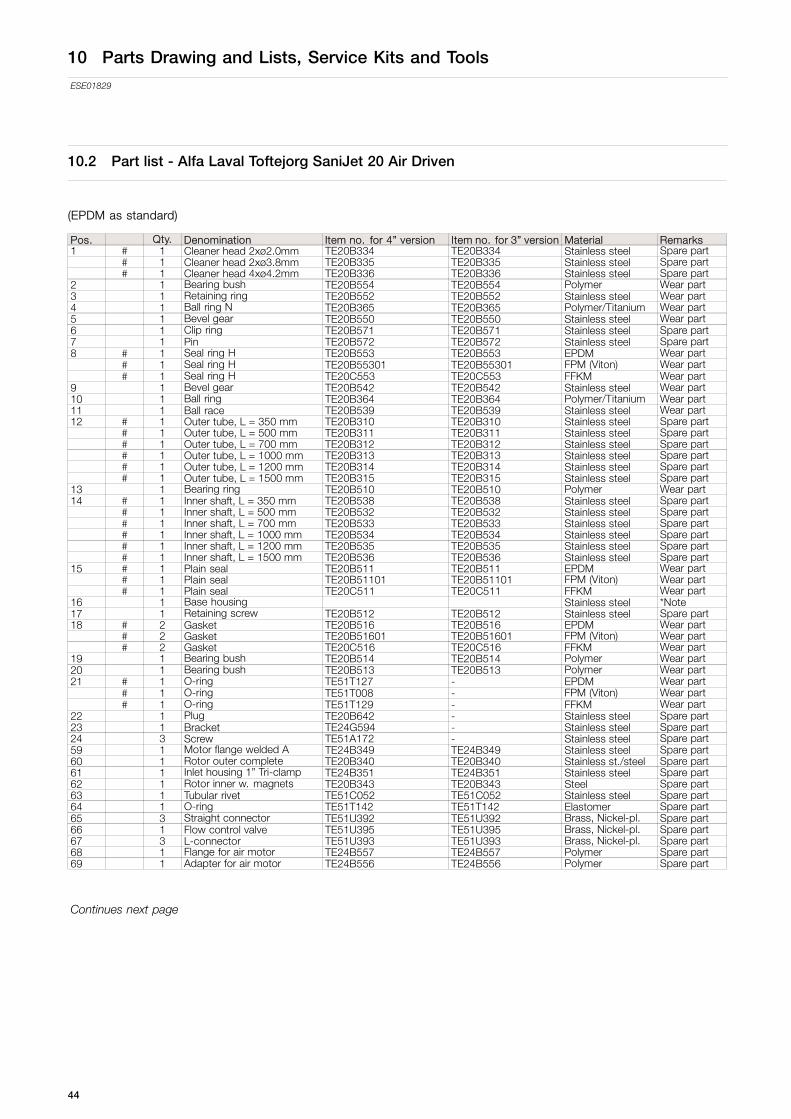
10.2 Part list - Alfa Laval Toftejorg SaniJet 20 Air Driven
(EPDM as standard)
Pos. Qty. Denomination Item no. for 4” version Item no. for 3” version Material Remarks1 # 1 Cleaner head 2xø2.0mm TE20B334 TE20B334 Stainless steel Spare part
# 1 Cleaner head 2xø3.8mm TE20B335 TE20B335 Stainless steel Spare part# 1 Cleaner head 4xø4.2mm TE20B336 TE20B336 Stainless steel Spare part
2 1 Bearing bush TE20B554 TE20B554 Polymer Wear part3 1 Retaining ring TE20B552 TE20B552 Stainless steel Wear part4 1 Ball ring N TE20B365 TE20B365 Polymer/Titanium Wear part5 1 Bevel gear TE20B550 TE20B550 Stainless steel Wear part6 1 Clip ring TE20B571 TE20B571 Stainless steel Spare part7 1 Pin TE20B572 TE20B572 Stainless steel Spare part8 # 1 Seal ring H TE20B553 TE20B553 EPDM Wear part
# 1 Seal ring H TE20B55301 TE20B55301 FPM (Viton) Wear part# 1 Seal ring H TE20C553 TE20C553 FFKM Wear part
9 1 Bevel gear TE20B542 TE20B542 Stainless steel Wear part10 1 Ball ring TE20B364 TE20B364 Polymer/Titanium Wear part11 1 Ball race TE20B539 TE20B539 Stainless steel Wear part12 # 1 Outer tube, L = 350 mm TE20B310 TE20B310 Stainless steel Spare part
# 1 Outer tube, L = 500 mm TE20B311 TE20B311 Stainless steel Spare part# 1 Outer tube, L = 700 mm TE20B312 TE20B312 Stainless steel Spare part# 1 Outer tube, L = 1000 mm TE20B313 TE20B313 Stainless steel Spare part# 1 Outer tube, L = 1200 mm TE20B314 TE20B314 Stainless steel Spare part# 1 Outer tube, L = 1500 mm TE20B315 TE20B315 Stainless steel Spare part
13 1 Bearing ring TE20B510 TE20B510 Polymer Wear part14 # 1 Inner shaft, L = 350 mm TE20B538 TE20B538 Stainless steel Spare part
# 1 Inner shaft, L = 500 mm TE20B532 TE20B532 Stainless steel Spare part# 1 Inner shaft, L = 700 mm TE20B533 TE20B533 Stainless steel Spare part# 1 Inner shaft, L = 1000 mm TE20B534 TE20B534 Stainless steel Spare part# 1 Inner shaft, L = 1200 mm TE20B535 TE20B535 Stainless steel Spare part# 1 Inner shaft, L = 1500 mm TE20B536 TE20B536 Stainless steel Spare part
15 # 1 Plain seal TE20B511 TE20B511 EPDM Wear part# 1 Plain seal TE20B51101 TE20B51101 FPM (Viton) Wear part# 1 Plain seal TE20C511 TE20C511 FFKM Wear part
16 1 Base housing TE24G500 TE24B500 Stainless steel *Note17 1 Retaining screw TE20B512 TE20B512 Stainless steel Spare part18 # 2 Gasket TE20B516 TE20B516 EPDM Wear part
# 2 Gasket TE20B51601 TE20B51601 FPM (Viton) Wear part# 2 Gasket TE20C516 TE20C516 FFKM Wear part
19 1 Bearing bush TE20B514 TE20B514 Polymer Wear part20 1 Bearing bush TE20B513 TE20B513 Polymer Wear part21 # 1 O-ring TE51T127 - EPDM Wear part
# 1 O-ring TE51T008 - FPM (Viton) Wear part# 1 O-ring TE51T129 - FFKM Wear part
22 1 Plug TE20B642 - Stainless steel Spare part23 1 Bracket TE24G594 - Stainless steel Spare part24 3 Screw TE51A172 - Stainless steel Spare part59 1 Motor flange welded A TE24B349 TE24B349 Stainless steel Spare part60 1 Rotor outer complete TE20B340 TE20B340 Stainless st./steel Spare part61 1 Inlet housing 1” Tri-clamp TE24B351 TE24B351 Stainless steel Spare part62 1 Rotor inner w. magnets TE20B343 TE20B343 Steel Spare part63 1 Tubular rivet TE51C052 TE51C052 Stainless steel Spare part64 1 O-ring TE51T142 TE51T142 Elastomer Spare part65 3 Straight connector TE51U392 TE51U392 Brass, Nickel-pl. Spare part66 1 Flow control valve TE51U395 TE51U395 Brass, Nickel-pl. Spare part67 3 L-connector TE51U393 TE51U393 Brass, Nickel-pl. Spare part68 1 Flange for air motor TE24B557 TE24B557 Polymer Spare part69 1 Adapter for air motor TE24B556 TE24B556 Polymer Spare part
Continues next page
44

10 Parts Drawing and Lists, Service Kits and Tools
ESE01829
Continued from previous page
Pos. Qty. Denomination Item no. for 4” version Item no. for 3” version Material Remarks70 1 Screw TE51A096 TE51A096 Stainless steel Spare part71 1 O-ring TE51T143 TE51T143 Elastomer Spare part72 6 Washer TE51B013 TE51B013 Stainless steel Spare part73 4 Screw TE51A097 TE51A097 Stainless steel Spare part74 1 Wire for grounding TE24B353 TE24B353 Stainless steel/alu. Spare part75 2 Screw TE51A112 TE51A112 Stainless steel Spare part76 2 Air tubing TE51U397 TE51U397 Polymer Spare part77 2 L-connector TE51U394 TE51U394 Brass, Nickel-pl. Spare part78 1 Air motor TE51U009 TE51U009 Spare part79 1 Plug TE51U396 TE51U396 Brass, Nickel-pl. Spare part80 3 Screw TE51A100 TE51A100 Stainless steel Spare part81 1 Motor cover TE24B348 TE24B348 Stainless steel Spare part
# Configuration according to delivery note/orderPlease note that some of the polymer parts are in PEEK, which is not resistant to concentrated sulfuric acid.*Note: Position 16 is not sold as single spare part component but only as part of a machine maintenance/repair order. For further informationplease contact Alfa Laval Customer Support.
Available add-onsAvailable add-on´s regarding material certificates, Declaration of Compliance and Q-doc documents, see page 41 for moreinformation.
45

10 Parts Drawing and Lists, Service Kits and Tools
ESE01829
10.3 Part list - Alfa Laval Toftejorg SaniJet 20 Air Driven improved surface finish
(EPDM as standard)
Pos. Qty. Denomination Item no. for 4” version Item no. for 3” version Material Remarks1 # 1 Cleaner head 2xø2.0mm TE20E334 TE20E334 Stainless steel Spare part
# 1 Cleaner head 2xø3.8mm TE20E335 TE20E335 Stainless steel Spare part# 1 Cleaner head 4xø4.2mm TE20E336 TE20E336 Stainless steel Spare part
2 1 Bearing bush TE20B554 TE20B554 Polymer Wear part3 1 Retaining ring TE20E552 TE20E552 Stainless steel Wear part4 1 Ball ring N TE20B365 TE20B365 Polymer/Titanium Wear part5 1 Bevel gear TE20E550 TE20E550 Stainless steel Wear part6 1 Clip ring TE20E571 TE20E571 Stainless steel Spare part7 1 Pin TE20E572 TE20E572 Stainless steel Spare part8 # 1 Seal ring H TE20B553 TE20B553 EPDM Wear part
# 1 Seal ring H TE20B55301 TE20B55301 FPM (Viton) Wear part# 1 Seal ring H TE20C553 TE20C553 FFKM Wear part
9 1 Bevel gear TE20E542 TE20E542 Stainless steel Wear part10 1 Ball ring TE20B364 TE20B364 Polymer/Titanium Wear part11 1 Ball race TE20E539 TE20E539 Stainless steel Wear part12 # 1 Outer tube, L = 350 mm TE20E310 TE20E310 Stainless steel Spare part
# 1 Outer tube, L = 500 mm TE20E311 TE20E311 Stainless steel Spare part# 1 Outer tube, L = 700 mm TE20E312 TE20E312 Stainless steel Spare part# 1 Outer tube, L = 1000 mm TE20E313 TE20E313 Stainless steel Spare part# 1 Outer tube, L = 1200 mm TE20E314 TE20E314 Stainless steel Spare part# 1 Outer tube, L = 1500 mm TE20E315 TE20E315 Stainless steel Spare part
13 1 Bearing ring TE20B510 TE20B510 Polymer Wear part14 # 1 Inner shaft, L = 350 mm TE20E538 TE20E538 Stainless steel Spare part
# 1 Inner shaft, L = 500 mm TE20E532 TE20E532 Stainless steel Spare part# 1 Inner shaft, L = 700 mm TE20E533 TE20E533 Stainless steel Spare part# 1 Inner shaft, L = 1000 mm TE20E534 TE20E534 Stainless steel Spare part# 1 Inner shaft, L = 1200 mm TE20E535 TE20E535 Stainless steel Spare part# 1 Inner shaft, L = 1500 mm TE20E536 TE20E536 Stainless steel Spare part
15 # 1 Plain seal TE20B511 TE20B511 EPDM Wear part# 1 Plain seal TE20B51101 TE20B51101 FPM (Viton) Wear part# 1 Plain seal TE20C511 TE20C511 FFKM Wear part
16 1 Base housing TE24F500 TE24E500 Stainless steel *Note17 1 Retaining screw TE20B512 TE20B512 Stainless steel Spare part18 # 2 Gasket TE20B516 TE20B516 EPDM Wear part
# 2 Gasket TE20B51601 TE20B51601 FPM (Viton) Wear part# 2 Gasket TE20C516 TE20C516 FFKM Wear part
19 1 Bearing bush TE20B514 TE20B514 Polymer Wear part20 1 Bearing bush TE20B513 TE20B513 Polymer Wear part21 # 1 O-ring TE51T127 - EPDM Wear part
# 1 O-ring TE51T008 - FPM (Viton) Wear part# 1 O-ring TE51T129 - FFKM Wear part
22 1 Plug TE20E642 - Stainless steel Spare part23 1 Bracket TE24F594 - Stainless steel Spare part24 3 Screw TE20E654 - Stainless steel Spare part59 1 Motor flange welded A TE24E346 TE24E346 Stainless steel Spare part60 1 Rotor outer complete TE20E340 TE20E340 Stainless steel/steel Spare part61 1 Inlet housing 1” Tri-clamp TE24E351 TE24E351 Stainless steel Spare part62 1 Rotor inner w. magnets TE20B343 TE20B343 Steel Spare part63 1 Tubular rivet TE51C052 TE51C052 Stainless steel Spare part64 1 O-ring TE51T142 TE51T142 Elastomer Spare part65 3 Straight connector TE51U392 TE51U392 Brass, Nickel-pl. Spare part66 1 Flow control valve TE51U395 TE51U395 Brass, Nickel-pl. Spare part67 3 L-connector TE51U393 TE51U393 Brass, Nickel-pl. Spare part68 1 Flange for air motor TE24B557 TE24B557 Polymer Spare part69 1 Adapter for air motor TE24B556 TE24B556 Polymer Spare part
Continues next page
46

10 Parts Drawing and Lists, Service Kits and Tools
ESE01829
Continued from previous page
Pos. Qty. Denomination Item no. for 4” version Item no. for 3” version Material Remarks70 1 Screw TE51A096 TE51A096 Stainless steel Spare part71 1 O-ring TE51T143 TE51T143 Elastomer Spare part72 6 Washer TE51B013 TE51B013 Stainless steel Spare part73 4 Screw TE51A097 TE51A097 Stainless steel Spare part74 1 Wire for grounding TE24B353 TE24B353 Stainless steel/alu. Spare part75 2 Screw TE51A112 TE51A112 Stainless steel Spare part76 2 Air tubing TE51U397 TE51U397 Polymer Spare part77 2 L-connector TE51U394 TE51U394 Brass, Nickel-pl. Spare part78 1 Air motor TE51U009 TE51U009 Spare part79 1 Plug TE51U396 TE51U396 Brass, Nickel-pl. Spare part80 3 Screw TE51A100 TE51A100 Stainless steel Spare part81 1 Motor cover TE24B348 TE24B348 Stainless steel Spare part
# Configuration according to delivery note/orderPlease note that some of the polymer parts are in PEEK, which is not resistant to concentrated sulfuric acid.*Note: Position 16 is not sold as single spare part component but only as part of a machine maintenance/repair order. For further informationplease contact Alfa Laval Customer Support.
Available add-onsAvailable add-on´s regarding material certificates, Declaration of Compliance and Q-doc documents, see page 41 for moreinformation.
47

10 Parts Drawing and Lists, Service Kits and Tools
ESE01829
10.4 Part list - Alfa Laval Toftejorg SaniJet 20 Air Driven Hastelloy
(FFKM as standard)
Pos. Qty. Denomination Item no. for 4” version Item no. for 3” version Material Remarks1 # 1 Cleaner head 2xø2.0mm TE20C334 TE20C334 Alloy Spare part
# 1 Cleaner head 2xø3.8mm TE20C335 TE20C335 Alloy Spare part# 1 Cleaner head 4xø4.2mm TE20C336 TE20C336 Alloy Spare part
2 1 Bearing bush TE20B554 TE20B554 Polymer Wear part3 1 Retaining ring TE20C552 TE20C552 Alloy Wear part4 1 Ball ring N TE20C361 TE20C361 Polymer/Titanium Wear part5 1 Bevel gear TE20C550 TE20C550 Alloy Wear part6 1 Clip ring TE20C571 TE20C571 Alloy Spare part7 1 Pin TE20C655 TE20C655 Alloy Spare part8 1 Seal ring H TE20C553 TE20C553 FFKM Wear part9 1 Bevel gear TE20C542 TE20C542 Alloy Wear part10 1 Ball ring TE20C360 TE20C360 Polymer/Titanium Wear part11 1 Ball race TE20C539 TE20C539 Alloy Wear part12 # 1 Outer tube, L = 350 mm TE20C310 TE20C310 Alloy Spare part
# 1 Outer tube, L = 500 mm TE20C311 TE20C311 Alloy Spare part# 1 Outer tube, L = 700 mm TE20C312 TE20C312 Alloy Spare part# 1 Outer tube, L = 1000 mm TE20C313 TE20C313 Alloy Spare part# 1 Outer tube, L = 1200 mm TE20C314 TE20C314 Alloy Spare part# 1 Outer tube, L = 1500 mm TE20C315 TE20C315 Alloy Spare part
13 1 Bearing ring TE20B510 TE20B510 Polymer Wear part14 # 1 Inner shaft, L = 350 mm TE20C538 TE20C538 Alloy Spare part
# 1 Inner shaft, L = 500 mm TE20C532 TE20C532 Alloy Spare part# 1 Inner shaft, L = 700 mm TE20C533 TE20C533 Alloy Spare part# 1 Inner shaft, L = 1000 mm TE20C534 TE20C534 Alloy Spare part# 1 Inner shaft, L = 1200 mm TE20C535 TE20C535 Alloy Spare part# 1 Inner shaft, L = 1500 mm TE20C536 TE20C536 Alloy Spare part
15 1 Plain seal TE20C511 TE20C511 FFKM Wear part16 1 Base housing TE24H500 TE24C500 Alloy *Note17 1 Retaining screw TE20B512 TE20B512 Stainless steel Spare part18 2 Gasket TE20C516 TE20C516 FFKM Wear part19 1 Bearing bush TE20B514 TE20B514 Polymer Wear part20 1 Bearing bush TE20B513 TE20B513 Polymer Wear part21 1 O-ring TE51T129 - FFKM Wear part22 1 Plug TE20C642 - Alloy Spare part23 1 Bracket TE24G594 - Stainless steel Spare part24 3 Screw TE51A172 - Stainless steel Spare part59 Motor flange welded A TE24C346 TE24C346 Alloy Spare part60 1 Rotor outer complete TE20C340 TE20C340 Alloy Spare part61 1 Inlet housing 1” Tri-clamp TE24C351 TE24C351 Alloy Spare part62 1 Rotor inner w. magnets TE20B343 TE20B343 Steel Spare part63 1 Tubular rivet TE51C052 TE51C052 Stainless steel Spare part64 1 O-ring TE51T142 TE51T142 Elastomer Spare part65 3 Straight connector TE51U392 TE51U392 Brass, Nickel-pl. Spare part66 1 Flow control valve TE51U395 TE51U395 Brass, Nickel-pl. Spare part67 3 L-connector TE51U393 TE51U393 Brass, Nickel-pl. Spare part69 1 Adapter for air motor TE24B556 TE24B556 Polymer Spare part68 1 Flange for air motor TE24B557 TE24B557 Polymer Spare part
Continues next page
48

10 Parts Drawing and Lists, Service Kits and Tools
ESE01829
Continued from previous page
Pos. Qty. Denomination Item no. for 4” version Item no. for 3” version Material Remarks70 1 Screw TE51A096 TE51A096 Stainless steel Spare part71 1 O-ring TE51T143 TE51T143 Elastomer Spare part72 6 Washer TE51B013 TE51B013 Stainless steel Spare part73 4 Screw TE51A097 TE51A097 Stainless steel Spare part74 1 Wire for grounding TE24B353 TE24B353 Stainless steel/alu. Spare part75 2 Screw TE51A112 TE51A112 Stainless steel Spare part76 2 Air tubing TE51U397 TE51U397 Polymer Spare part77 2 L-connector TE51U394 TE51U394 Brass, Nickel-pl. Spare part78 1 Air motor TE51U009 TE51U009 Spare part79 1 Plug TE51U396 TE51U396 Brass, Nickel-pl. Spare part80 3 Screw TE51A100 TE51A100 Stainless steel Spare part81 1 Motor cover TE24B348 TE24B348 Stainless steel Spare part
# Configuration according to delivery note/orderPlease note that some of the polymer parts are in PEEK, which is not resistant to concentrated sulfuric acid.*Note: Position 16 is not sold as single spare part component but only as part of a machine maintenance/repair order. For further informationplease contact Alfa Laval Customer Support.
Available add-onsAvailable add-on´s regarding material certificates, Declaration of Compliance and Q-doc documents, see page 41 for moreinformation.
49

10 Parts Drawing and Lists, Service Kits and Tools
ESE01829
10.5 Part List - Alfa Laval Toftejorg SaniJet 20 Air Driven Hastelloy improved surface finish
(FFKM as standard)
Pos. Qty. Denomination Item no. for 4” version Item no. for 3” version Material Remarks1 # 1 Cleaner head 2xø2.0mm TE24J334 TE24J334 Alloy Spare part
# 1 Cleaner head 2xø3.8mm TE24J335 TE24J335 Alloy Spare part# 1 Cleaner head 4xø4.2mm TE24J336 TE24J336 Alloy Spare part
2 1 Bearing bush TE20B554 TE20B554 Polymer Wear part3 1 Retaining ring TE24J552 TE24J552 Alloy Wear part4 1 Ball ring N TE20C361 TE20C361 Polymer/Titanium Wear part5 1 Bevel gear TE24J550 TE24J550 Alloy Wear part6 1 Clip ring TE24J571 TE24J571 Alloy Spare part7 1 Pin TE24J655 TE24J655 Alloy Spare part8 1 Seal ring H TE20C553 TE20C553 FFKM Wear part9 1 Bevel gear TE24J542 TE24J542 Alloy Wear part10 1 Ball ring TE20C360 TE20C360 Polymer/Titanium Wear part11 1 Ball race TE24J539 TE24J539 Alloy Wear part12 # 1 Outer tube, L = 350 mm TE24J310 TE24J310 Alloy Spare part
# 1 Outer tube, L = 500 mm TE24J311 TE24J311 Alloy Spare part# 1 Outer tube, L = 700 mm TE24J312 TE24J312 Alloy Spare part# 1 Outer tube, L = 1000 mm TE24J313 TE24J313 Alloy Spare part# 1 Outer tube, L = 1200 mm TE24J314 TE24J314 Alloy Spare part# 1 Outer tube, L = 1500 mm TE24J315 TE24J315 Alloy Spare part
13 1 Bearing ring TE20B510 TE20B510 Polymer Wear part14 # 1 Inner shaft, L = 350 mm TE24J538 TE24J538 Alloy Spare part
# 1 Inner shaft, L = 500 mm TE24J532 TE24J532 Alloy Spare part# 1 Inner shaft, L = 700 mm TE24J533 TE24J533 Alloy Spare part# 1 Inner shaft, L = 1000 mm TE24J534 TE24J534 Alloy Spare part# 1 Inner shaft, L = 1200 mm TE24J535 TE24J535 Alloy Spare part# 1 Inner shaft, L = 1500 mm TE24J536 TE24J536 Alloy Spare part
15 1 Plain seal TE20C511 TE20C511 FFKM Wear part16 1 Base housing TE24J500 TE24D500 Alloy *Note17 1 Retaining screw TE20B512 TE20B512 Stainless steel Spare part18 2 Gasket TE20C516 TE20C516 FFKM Wear part19 1 Bearing bush TE20B514 TE20B514 Polymer Wear part20 1 Bearing bush TE20B513 TE20B513 Polymer Wear part21 1 O-ring TE51T129 FFKM Wear part22 1 Plug TE24J642 - Alloy Spare part23 1 Bracket TE24F594 - Stainless steel Spare part24 3 Screw TE20E654 - Stainless steel Spare part59 1 Motor flange welded A TE24J346 TE24J346 Alloy Spare part60 1 Rotor outer complete TE24J340 TE24J340 Alloy Spare part61 1 Inlet housing 1” Tri-clamp TE24J351 TE24J351 Alloy Spare part62 1 Rotor inner w. magnets TE20B343 TE20B343 Steel Spare part63 1 Tubular rivet TE51C052 TE51C052 Stainless steel Spare part64 1 O-ring TE51T142 TE51T142 Elastomer Spare part65 3 Straight connector TE51U392 TE51U392 Brass, Nickel-pl. Spare part66 1 Flow control valve TE51U395 TE51U395 Brass, Nickel-pl. Spare part67 3 L-connector TE51U393 TE51U393 Brass, Nickel-pl. Spare part68 1 Flange for air motor TE24B557 TE24B557 Polymer Spare part69 1 Adapter for air motor TE24B556 TE24B556 Polymer Spare part
Continues next page
50

10 Parts Drawing and Lists, Service Kits and Tools
ESE01829
Continued from previous page
Pos. Qty. Denomination Item no. for 4” version Item no. for 3” version Material Remarks70 1 Screw TE51A096 TE51A096 Stainless steel Spare part71 1 O-ring TE51T143 TE51T143 Elastomer Spare part72 6 Washer TE51B013 TE51B013 Stainless steel Spare part73 4 Screw TE51A097 TE51A097 Stainless steel Spare part74 1 Wire for grounding TE24B353 TE24B353 Stainless steel/alu. Spare part75 2 Screw TE51A112 TE51A112 Stainless steel Spare part76 2 Air tubing TE51U397 TE51U397 Polymer Spare part77 2 L-connector TE51U394 TE51U394 Brass, Nickel-pl. Spare part78 1 Air motor TE51U009 TE51U009 Spare part79 1 Plug TE51U396 TE51U396 Brass, Nickel-pl. Spare part80 3 Screw TE51A100 TE51A100 Stainless steel Spare part81 1 Motor cover TE24B348 TE24B348 Stainless steel Spare part
# Configuration according to delivery note/orderPlease note that some of the polymer parts are in PEEK, which is not resistant to concentrated sulfuric acid.*Note: Position 16 is not sold as single spare part component but only as part of a machine maintenance/repair order. For further informationplease contact Alfa Laval Customer Support.
Available add-onsAvailable add-on´s regarding material certificates, Declaration of Compliance and Q-doc documents, see page 41 for moreinformation.
51

10 Parts Drawing and Lists, Service Kits and Tools
ESE01829
10.6 Service Kits
Service intervals
300 hour 300 hour 300 hour1 year 1 year 1 year
Service Kit:TE20B294,
TE20B295 orTE20C295
Service Kit:TE20B294,
TE20B295 orTE20C295
Service Kit:TE20B294,
TE20B295 orTE20C295
Service Kit in Viton for Alfa Laval Toftejorg SaniJet 20 air driven versionArticle no. TE20B294Parts list
Pos. Qty Denomination
9 2 Gasket D12.14 1 Bearing bush D112.15 1 Bearing bush D212.4 1 O-ring12.7 1 Plain seal S12.9 1 Bearing ring, top13 1 Seal ring H
Service Kit in EPDM for Alfa Laval Toftejorg SaniJet 20 air driven versionArticle no. TE20B295Parts list
Pos. Qty Denomination
9 2 Gasket D12.14 1 Bearing bush D112.15 1 Bearing bush D212.4 1 O-ring12.7 1 Plain seal S12.9 1 Bearing ring, top13 1 Seal ring H
52

10 Parts Drawing and Lists, Service Kits and Tools
ESE01829
Service Kit in Perlast for Alfa Laval Toftejorg SaniJet 20 air driven versionArticle no. TE20C295Parts list
Pos. Qty Denomination
9 2 Gasket D12.14 1 Bearing bush D112.15 1 Bearing bush D212.4 1 O-ring12.7 1 Plain seal S12.9 1 Bearing ring, top13 1 Seal ring H
Available add-on´s regarding material certificates, Declaration of Compliance and Q-doc documents, see page 41 for moreinformation.
10.7 Tools
Socket wrench w. pin . . . . . . . . . . . . . . . TE462AHook spanner . . . . . . . . . . . . . . . . . . . . . . . TE20B701
53

11 General information
ESE01829
11.1 Service and Repair
Upon every return of a product, no matter if for modifications or repair, it is necessary to contact your local Alfa Laval office toguarantee a quick execution of your request.
You will receive instructions regarding the return procedure from your local Alfa Laval office. Be sure to follow the instructionsclosely.
11.2 How to order Spare Parts
On the Part List Drawing (page 43) as well as on all instruction drawings, the individual parts have a position number, which is thesame on all drawings. From the position number, the part is easily identified in the Reference Lists of Parts, page 44 ff.
Individual parts should always be ordered from the Reference Lists of Parts, page 44 ff. Ref. No. and description should beclearly stated.
Please also quote the type of machine and serial No. This will help us to help you. The type and serial numbers are laserengraved on the Base house of the tank cleaning machine.
Note: In cases where spare parts are ordered for machines originally delivered with Q-doc (Equipment Documentation),please state this information on your ordering form together with the machine type and serial number. This is to ensure fulltraceability henceforward.
Note: In connection with ordering of spare parts for machines originally delivered with Q-doc + FAT-SAT (QualificationDocumentation) please note that all service and repair should be performed by Alfa Laval Kolding A/S, Denmark, see page 25“6.5 Service and repair of machines ordered with Q-doc and with Q-doc + FAT-SAT”.
11.3 How to contact Alfa Laval Kolding A/S
For further information please feel free to contact:
Alfa Laval Kolding A/S31, Albuen - DK 6000 Kolding - DenmarkRegistration number: 30938011Tel switchboard: +45 79 32 22 00 - Fax switchboard: +45 79 32 25 80www.toftejorg.com, www.alfalaval.dk - [email protected]
Contact details for all countries are continually updated on our websites
54

12 Miscellaneous
ESE01829
12.1 Declarations of Conformity per EN 10204 2.2
Only valid for EU countries
55

12 Miscellaneous
ESE01829
Only valid for EU countries
56

12 Miscellaneous
ESE01829
12.2 ATEX - Specific conditions of use
57

How to contact Alfa LavalContact details for all countries arecontinually updated on our website.Please visit www.alfalaval.com to access the information directly.
© Alfa Laval Corporate ABThis document and its contents is owned by Alfa Laval Corporate AB and protected by laws governing intellectual property and thereto related rights. It is the responsibility of the user of thisdocument to comply with all applicable intellectual property laws. Without limiting any rights related to this document, no part of this document may be copied, reproduced or transmitted in anyform or by any means (electronic, mechanical, photocopying, recording, or otherwise), or for any purpose, without the expressed permission of Alfa Laval Corporate AB. Alfa Laval Corporate ABwill enforce its rights related to this document to the fullest extent of the law, including the seeking of criminal prosecution.