Instruction Manual LongArm™ SDL6 Remote Operator for ...
22
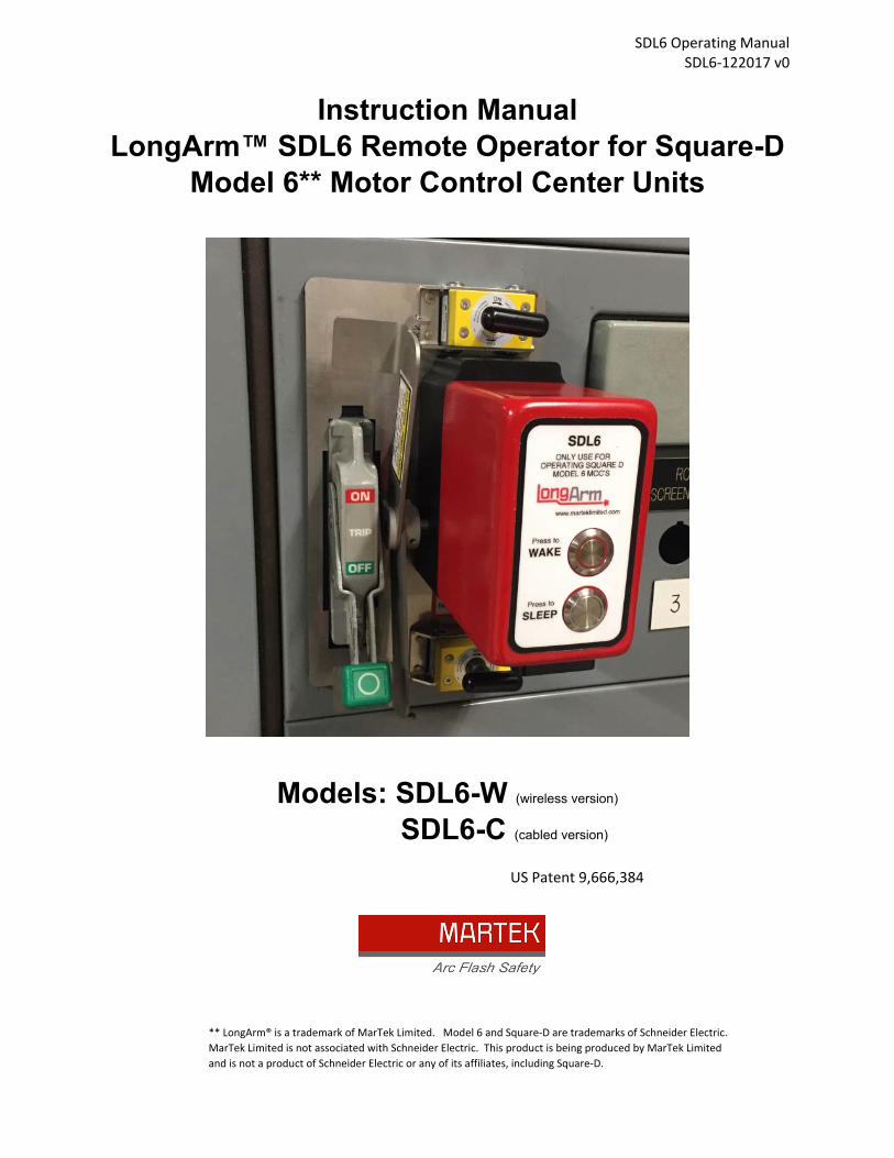
SDL6 Operating Manual SDL6‐122017 v0 Instruction Manual LongArm™ SDL6 Remote Operator for Square-D Model 6** Motor Control Center Units Models: SDL6-W (wireless version) SDL6-C (cabled version) ** LongArm® is a trademark of MarTek Limited. Model 6 and Square‐D are trademarks of Schneider Electric. MarTek Limited is not associated with Schneider Electric. This product is being produced by MarTek Limited and is not a product of Schneider Electric or any of its affiliates, including Square‐D. US Patent 9,666,384
Transcript of Instruction Manual LongArm™ SDL6 Remote Operator for ...
SDL6 Operating Manual SDL6‐122017 v0
Instruction Manual LongArm™ SDL6 Remote Operator for Square-D
Model 6** Motor Control Center Units
Models: SDL6-W (wireless version) SDL6-C (cabled version)
** LongArm® is a trademark of MarTek Limited. Model 6 and Square‐D are trademarks of Schneider Electric.
MarTek Limited is not associated with Schneider Electric. This product is being produced by MarTek Limited
and is not a product of Schneider Electric or any of its affiliates, including Square‐D.
US Patent 9,666,384

SDL6 Operating Manual SDL6‐122017 v0
(intentionally left blank)

SDL6 Operating Manual SDL6‐122017 v0
Table of Contents
1.0 Introduction…………………………………………....…………………………. 1 2.0 General Safety Information……………………………………………………... 2
2.1 Arc-Blast Hazards………………………………………………………. 2 2.2 Battery Hazards…………………………………………………….…… 3 2.3 Magnet Hazards………………………………………………………... 3 2.4 Pinch Point Hazards……………………………………………………. 4 2.5 Radio Frequency………………………………………………..………. 4
3.0 Battery Information …………………………………………………………….…. 5 3.1 Removing and Replacing the Battery in the SDL6 Actutor……...….. 6 3.2 Replacing the Battery in the RTL-1 Remote Transmitter ………..…. 9
4.0 Operation…………………………………………………………………………...10 4.0 Mounting Footprint……………………………………………………….11 4.1 Installing the SDL6……………………………………………………….12 4.2 Operating the SDL6……………………………………………………...14 4.3 Removing the SDL6……………………………………………………..15
5.0 Storage ……………………………………………………………………………. 16 6.0 Troubleshooting ………………………………………………………………….. 17
7.0 Specifications …………………………………………………………………….. 18 8.0 Contacting the Manufacturer …………………………………………………… 19

SDL6 Operating Manual SDL6‐122017 v0
1 © MarTek Limited. All rights reserved.
Use and Operation Instructions SDL6 Remote Operator for Square D Model 6 Motor Control Centers 1.0 Introduction The SDL6 is designed to remotely operate the ON/OFF handle on Square D Model 6 motor control center units with handles that are 4-1/2” in length (see Fig 1). Due to torque limitations, the SDL6 is also generally limited to 30, 60, and 100 amp rated MCC units. It will not work on Model 6 units with the Closed Door Racking (CDR) option (see Fig 2). The SDL6 installs on the MCC unit with magnets, so there is no modification required to your MCC in order to mount it. The SDL6 is designed to work in the most common installations. However, MCC’s are sometimes provided with auxiliary devices or nameplates in the MCC unit door that could interfere with mounting. Similarly, it is unlikely that it will operate most horizontally operated space saving units. See Section 4.1 for additional information on the required mounting footprint to verify if your installation has the required space available. When viewing the ON/OFF handle on the MCC such that the handle is in the downward position when the unit is OFF, the SDL6 actuator gearbox assembly must be installed to the right hand side of the ON/OFF switch. The SDL6 will not operate the ON/OFF switch if it is installed to the left side of the switch. The SDL6 is not designed, nor should be attempted, to be used on motor control centers other than those described here.
Figure 1
This is a typical switch that the SDL6 is intended to operate

SDL6 Operating Manual SDL6‐122017 v0
2 © MarTek Limited. All rights reserved.
The SDL6 is offered in two basic models – a wireless version (SDL6-W) and a cabled version (SDL6-C). The advantage of the wireless version is that there are no cables to deal with which makes it more convenient to use. The cabled version is offered for customers who prefer cable operated equipment.
2.0 General Safety Information:
2.1 Arc-blast Hazards The hazards associated with electrical arc-blasts are well documented. Studies conducted by numerous industries and professional organizations have sought to quantify the intensity of arc blast, the risks to personnel, and various methodologies for mitigating the risks. Without a doubt, increasing the distance between the arc and a human is the single greatest favorable factor in reducing injuries. Remote operation of electrical equipment is not a cure-all, but rather one more tool available for protecting workers while they are performing electrical switching. Using the SDL6 remote operating device for motor control centers may not negate the need for additional personal protective measures. The user is ultimately responsible for evaluating each situation to determine if additional protective measures are needed.
HAZARD OF ELECTRIC SHOCK, EXPLOSION, OR ARC FLASH • This equipment must only be installed by qualified personnel.
• Only use this equipment after reading and understanding all of the instructions contained in this manual.
• Follow electrical safe work practices. See NFPA 70E or CSA Z462
FAILURE TO FOLLOW THESE INSTRUCTIONS COULD RESULT IN DEATH OR SERIOUS INJURY
Figure 2
This is a Model 6 Closed Door Rackable (CDR) unit. The SDL6 will NOT work on this unit. (Contact MarTek for additional information on a remote operator)
SDL6 Operating Manual SDL6‐122017 v0
3 © MarTek Limited. All rights reserved.
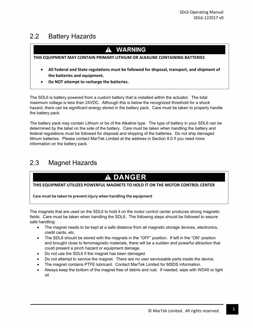
2.2 Battery Hazards
The SDL6 is battery powered from a custom battery that is installed within the actuator. The total maximum voltage is less than 24VDC. Although this is below the recognized threshold for a shock hazard, there can be significant energy stored in the battery pack. Care must be taken to properly handle the battery pack. The battery pack may contain Lithium or be of the Alkaline type. The type of battery in your SDL6 can be determined by the label on the side of the battery. Care must be taken when handling the battery and federal regulations must be followed for disposal and shipping of the batteries. Do not ship damaged lithium batteries. Please contact MarTek Limited at the address in Section 8.0 if you need more information on the battery pack.
2.3 Magnet Hazards The magnets that are used on the SDL6 to hold it on the motor control center produces strong magnetic fields. Care must be taken when handling the SDL6. The following steps should be followed to assure safe handling:
The magnet needs to be kept at a safe distance from all magnetic storage devices, electronics, credit cards, etc.
The SDL6 should be stored with the magnets in the “OFF” position. If left in the “ON” position and brought close to ferromagnetic materials, there will be a sudden and powerful attraction that could present a pinch hazard or equipment damage.
Do not use the SDL6 if the magnet has been damaged. Do not attempt to service the magnet. There are no user serviceable parts inside the device. The magnet contains PTFE lubricant. Contact MarTek Limited for MSDS information. Always keep the bottom of the magnet free of debris and rust. If needed, wipe with WD40 or light
oil.
THIS EQUIPMENT MAY CONTAIN PRIMARY LITHIUM OR ALKALINE CONTAINING BATTERIES
All Federal and State regulations must be followed for disposal, transport, and shipment of
the batteries and equipment.
Do NOT attempt to recharge the batteries.
THIS EQUIPMENT UTILIZES POWERFUL MAGNETS TO HOLD IT ON THE MOTOR CONTROL CENTER
Care must be taken to prevent injury when handling the equipment

SDL6 Operating Manual SDL6‐122017 v0
4 © MarTek Limited. All rights reserved.
2.4 Pinch Point Hazards The SDL6 is a motorized device with moving parts that will produce the opportunity for pinch point hazards. Steps have been taken in the design to help prevent a pinch point injury. One of these features is the safety switch integrated into the bottom of the unit. This safety switch prevents the SDL6 from energizing, or remaining energized, unless it is installed on a flat surface. Once the SDL6 is removed from the motor control center, it will automatically de-energize. However, this alone is not assurance that a pinch point injury cannot take place. In order to prevent a pinch point injury, the following procedures should be followed:
Install the SDL6 actuator on the MCC door prior to turning it on. Once the SDL6 is turned ON, do not touch or bring body parts near the actuator. Turn OFF the SDL6 actuator prior to removing it from the MCC door. Do NOT attempt to turn the SDL6 actuator ON unless it is installed and ready to use.
Additionally, the magnets used to hold the SDL6 actuator on the MCC door could present a pinch hazard. To prevent an injury the following procedures should be followed:
Only turn the magnets to the “ON” position when it is firmly against the metal surface of the MCC door.
Turning the magnets to the “ON” position prior to installing the SDL6 could cause a quick uncontrollable attraction to ferromagnetic materials in close proximity and present a serious pinch point injury.
Store the SDL6 actuator with the magnet in the “OFF” position.
2.5 Radio Frequency The wireless version of the SDL6 uses a radio transmitter and receiver to communicate. The transmitter and receiver operate in the 2.4GHz frequency band and is low power at 1mW. These are commercially available radios that have agency certification through the manufacturer. They are certified with the following agency approvals: United States – FCC FCC ID: OUR-XBEE The enclosed device complies with Part 15 of the FCC Rules. Operation is subject to the
following two conditions: (i.) this device may not cause harmful interference and (ii.) this device must accept any interference received, including interference that may cause undesired operation.
Canada – IC IC: 4214A-XBEE
THIS EQUIPMENT HAS MOVING PARTS THAT PRESENT PINCH POINT HAZARDS
Care must be taken to prevent injury when handling the equipment.

SDL6 Operating Manual SDL6‐122017 v0
5 © MarTek Limited. All rights reserved.
3.0 Battery Information SDL6 Actuator Battery The SDL6 is powered from a custom battery pack that has been pre-installed in the actuator. It consists of 15 single cell AA batteries connected in series to produce a nominal voltage of 22.5VDC. There are also two additional single cell AA batteries connected in series to produce a nominal voltage of 3.0VDC. The 17 total cells are packaged within the one replaceable battery pack. The 22.5VDC output is fused in the middle of the string to limit the current to 4.0 amps. The two following battery types are offered with SDL6:
Lithium/Iron Disulfide – this battery pack has been tested to 3,000+ operations before needing replaced. The individual cells have an advertised shelf life of 10-20 years depending upon the storage temperature. The advantage to this battery is that it is long lasting and will not require replacement as often as an alkaline battery. The disadvantages are that there are regulations that in certain circumstances could prevent shipping or transporting them by air freight and internationally. See Federal 49 CFR 173.185 and IATA regulations for additional information for shipping and transporting Lithium batteries. See Section 7.0 for additional specifications.
Alkaline – this battery pack has been tested to 1,500+ operations before needing replaced.
The individual cells have an advertised shelf life of one year, which is the dis-advantage of this battery. The advantage is that is can be easily shipped by air or internationally.
The type of battery installed in your SDL6 could be either the Lithium/Iron Disulfide type or the Alkaline depending on which type was ordered. The type of battery installed in your SDL6 can be determined by the label on the side of the battery. Both types of battery packs are custom designed to work with the SDL6 and are only available through MarTek Limited. Use only approved battery packs. MarTek Limited can provide assistance to assure that you order the correct battery. See Section 8.0 for information to contact MarTek Limited. RTL-1 Remote Transmitter The RTL-1 is a remote transmitter used with the wireless version of the SDL6. It is powered by a 9VDC battery. Replace this battery as needed with a commercially available 9VDC battery. An alkaline type is recommended, but not required. RCL-1 Remote Controller The RCL-1 is a remote controller used with the cabled version of the SDL6. It is powered from the SDL6 actuator through the cable and does not contain a battery.
THIS EQUIPMENT USES A CUSTOM DESIGNED BATTERY PACK.
DO NOT attempt to modify the battery pack or to install a battery pack not approved for use in the SDL6.
Doing so could cause equipment damage, fire, or personal injury.

SDL6 Operating Manual SDL6‐122017 v0
6 © MarTek Limited. All rights reserved.
3.1 Removing and Replacing the Battery in the SDL6 Actuator
The SDL6 actuator requires a custom battery. Do not attempt to use a non-approved battery. To obtain a replacement battery, see Section 3.0 for detailed information. Note: The actuator shown in the pictures in this section may be different than the SDL6, however, the steps to remove and replace the battery is the same as shown. To replace the battery, complete the following steps:
STEP 1 - Using Phillips screwdriver, remove four screws from battery cover plate. FIG 3.

SDL6 Operating Manual SDL6‐122017 v0
7 © MarTek Limited. All rights reserved.
STEP 2 – Remove battery cover plate and slide battery out.
FIG 4.
STEP 3 – Disconnect battery at connector.
FIG 5.
SDL6 Operating Manual SDL6‐122017 v0
8 © MarTek Limited. All rights reserved.
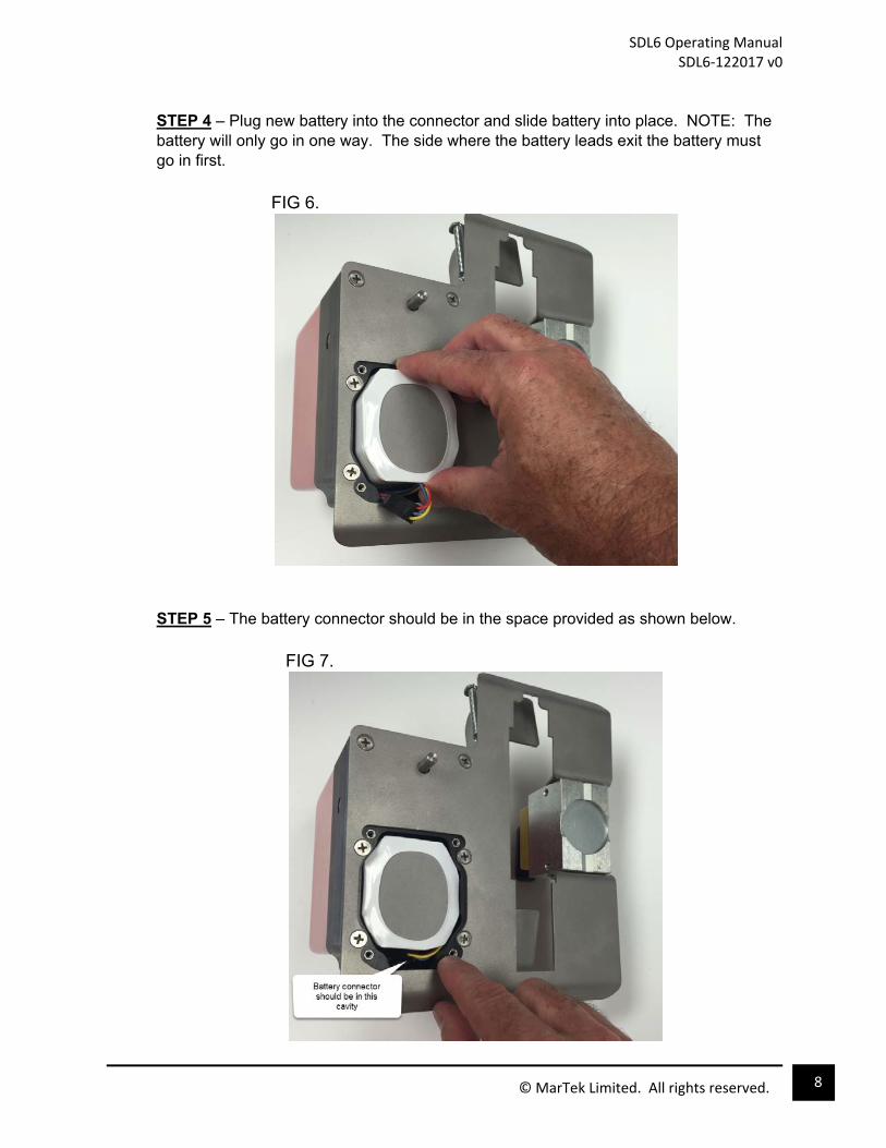
STEP 4 – Plug new battery into the connector and slide battery into place. NOTE: The battery will only go in one way. The side where the battery leads exit the battery must go in first. FIG 6.
STEP 5 – The battery connector should be in the space provided as shown below. FIG 7.
SDL6 Operating Manual SDL6‐122017 v0
9 © MarTek Limited. All rights reserved.
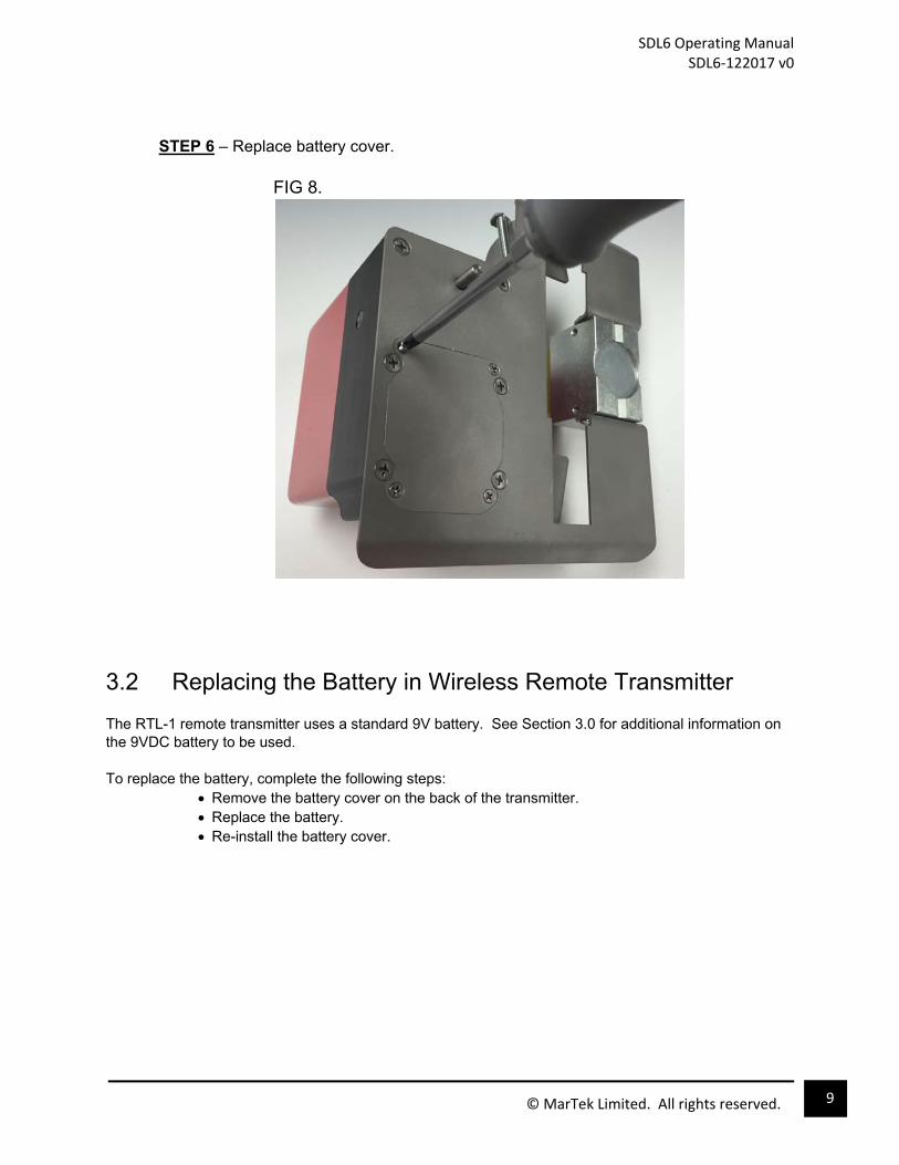
STEP 6 – Replace battery cover. FIG 8.
3.2 Replacing the Battery in Wireless Remote Transmitter The RTL-1 remote transmitter uses a standard 9V battery. See Section 3.0 for additional information on the 9VDC battery to be used. To replace the battery, complete the following steps:
Remove the battery cover on the back of the transmitter. Replace the battery. Re-install the battery cover.

SDL6 Operating Manual SDL6‐122017 v0
10 © MarTek Limited. All rights reserved.
4.0 Use and Operation of the SDL6 The SDL6 can be installed over the MCC operating handle regardless of the position of the handle (whether it is in the ON or OFF position). Care must be taken when installing SDL6 that the MCC handle is not inadvertently operated.
4.1 Mounting Footprint
Figure 9 shows the footprint of the SDL6 when mounted to an MCC bucket. This foot print shows the area that touches your equipment which is the area on your equipment that must be clear for mounting the SDL6.
FIG 9.
SDL6 Operating Manual SDL6‐122017 v0
11 © MarTek Limited. All rights reserved.
4.2 Installing the SDL6 on the MCC Door
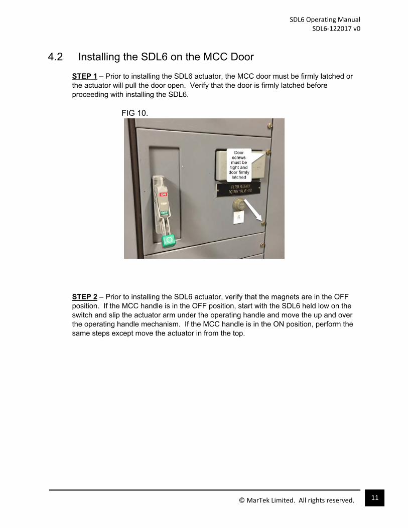
STEP 1 – Prior to installing the SDL6 actuator, the MCC door must be firmly latched or the actuator will pull the door open. Verify that the door is firmly latched before proceeding with installing the SDL6.
FIG 10.
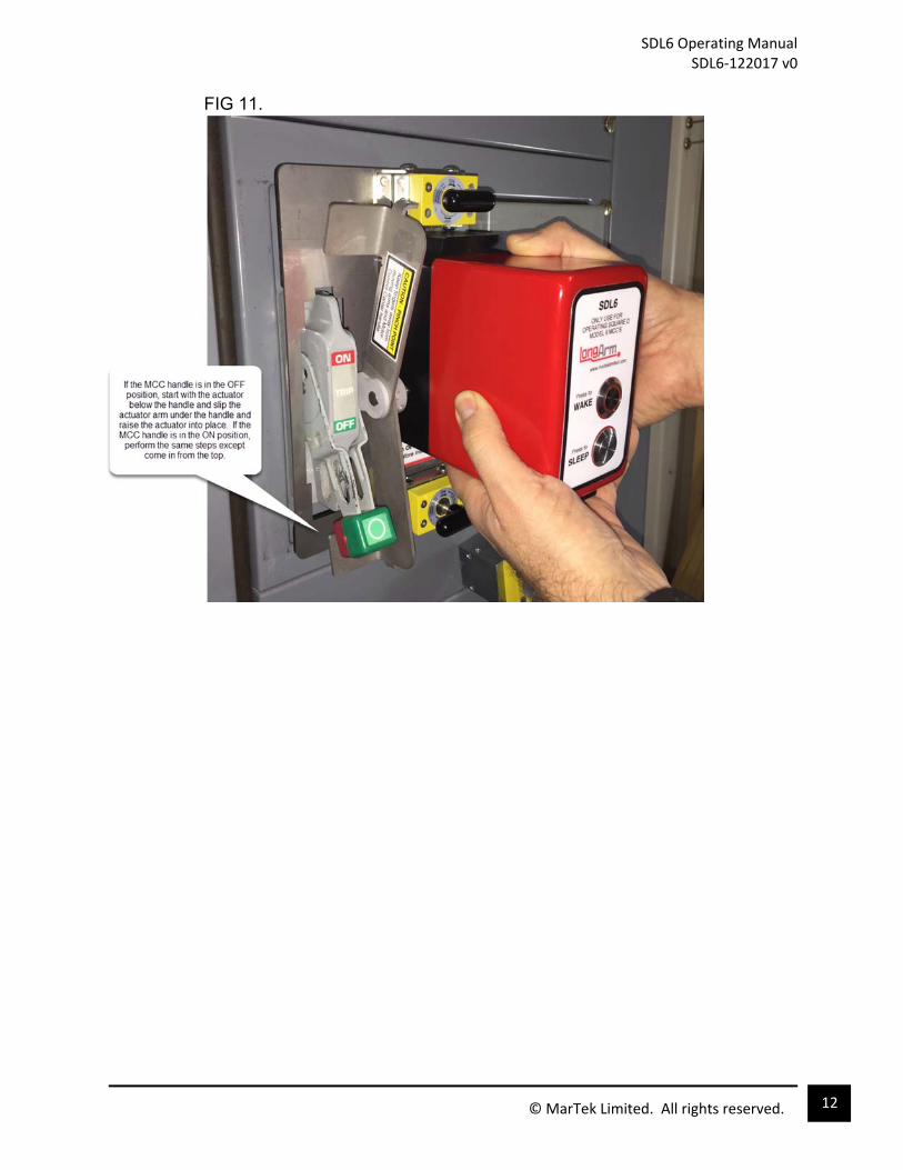
STEP 2 – Prior to installing the SDL6 actuator, verify that the magnets are in the OFF position. If the MCC handle is in the OFF position, start with the SDL6 held low on the switch and slip the actuator arm under the operating handle and move the up and over the operating handle mechanism. If the MCC handle is in the ON position, perform the same steps except move the actuator in from the top.
SDL6 Operating Manual SDL6‐122017 v0
12 © MarTek Limited. All rights reserved.
FIG 11.

SDL6 Operating Manual SDL6‐122017 v0
13 © MarTek Limited. All rights reserved.
STEP 3 – With actuator now flush against the MCC door, twist the magnet levers one-half turn clockwise to lock the magnet and actuator in place. FIG 12.
STEP 4 – For the wireless versions of the SDL6, the installation is complete and it is ready to operate. See Section 4.3 for the operating procedure. For the cabled version of the SDL6, the cable must be installed prior to proceeding. Attach the cable to both the actuator and the hand-held controller by inserting the cable in the connector and turning the ferrule clockwise to lock it in place. Once the cable is connected, see Section 4.3 for operation.

SDL6 Operating Manual SDL6‐122017 v0
14 © MarTek Limited. All rights reserved.
4.3 Operating the SDL6
STEP 1 – Press the WAKE button to power up the actuator.
FIG 3.
STEP 2 – While standing at a safe distance, press and hold the ENABLE button on the hand-held controller. The yellow light should illuminate. Then press and hold the button corresponding to the handle direction that is desired (ON or OFF). Both the ENABLE button and the ON or OFF button must be held simultaneously until the full stroke of the operating handle is complete. Then the buttons can be released and the actuator will return to its neutral position. NOTE: The actuator will power itself OFF after a couple minutes of no use. If it does power down, turn it back on by pressing the WAKE button. STEP 3 – When operating the SDL6 is completed, power the actuator OFF by pressing the SLEEP button.

SDL6 Operating Manual SDL6‐122017 v0
15 © MarTek Limited. All rights reserved.
4.4 Removing the SDL6
STEP 1 – Verify that the actuator is powered OFF by pressing the SLEEP button. DO NOT ATTEMPT TO REMOVE THE ACTUATOR WITH THE POWER ON AS THIS COULD CAUSE A PINCH POINT INJURY. STEP 2 – While firmly holding the actuator in your right hand, disengage the magnets by using your left hand to turn the magnet levers counter-clockwise. Lower or raise the actuator off the operating handle. STEP 3 – Disconnect cable (for cabled versions only) and return components to carrying case or store on the side of the MCC. (See Section 5.0 for details) FIG 14.

SDL6 Operating Manual SDL6‐122017 v0
16 © MarTek Limited. All rights reserved.
5.0 Storage The SDL6 is provided with a heavy duty carrying case that can be used to conveniently store the actuator and its necessary components. The carrying case and complete unit should be stored in a clean and cool environment. In order to make the SDL6 more readily available for use, the actuator and hand-held controller can also be stored on a ferromagnetic surface such as the side of the MCC (see Figure 15). Use the mounting magnet on the SDL6 to hold it in place and the hand-held controller has a magnet built in that will allow it to hold onto a steel metal surface as shown below. Storage on the side of an MCC is only recommended if the area is clean, dry, and cool (<90F) .
FIG 15.

SDL6 Operating Manual SDL6‐122017 v0
17 © MarTek Limited. All rights reserved.
6.0 Troubleshooting
Table 1
SYMPTOM SOLUTION The LED on the Wake button flashes and then the unit shuts down.
The battery in the SDL6 is low and must be replaced
The RTL-1 wireless transmitter won’t activate the SDL6
The problem could be caused if the transmitter is outside the 50-foot range. It is possible the problem could be due to a low battery in the RTL-1. Try replacing the battery.
The LED on the Wake button shuts off after a couple of minutes.
This is normal. The SDL6 will power down if not used within a couple of minutes in order to preserve the battery. Press the Wake button again to turn it back on.
The RCL-1 cabled hand-held controller will not activate the actuator.
Check that the control cable is connected.

SDL6 Operating Manual SDL6‐122017 v0
18 © MarTek Limited. All rights reserved.
7.0 Specifications Table 2
Voltage
SDL6 – 22.5VDC and 3.0VDC (custom designed battery available in Lithium or Alkaline. See Section 3.0 for more details) RTL1 – 9VDC RCL1 – 5VDC (powered from SDL6)
Lithium Battery (when supplied)
17 cells, (each cell is Ultimate Lithium Energizer L91) Output Voltage – 22.5VDC and 3.0VDC Battery net weight – 0.27kg Lithium Disulfide (Li/FeS2)content – less than 17g total Operating and Storage Temperature -40F to 140F (-40C to 60C) Shelf Life 20 years at 21C Designation (per cell) ANSI 15-LF, IEC-FR14505 (FR6) See Section 3.0 for additional information
Magnets
Two magnets with each magnet having 150lbs/68kg magnet strength, 18.5lbs/8.4kg sheer load.
Wireless Hand-held Controller (SDL6-W version only)
Operating frequency 2.4Ghz, 1mW output. 50-foot range (line of sight). Transmitter and actuator are paired so that the transmitter can only operate the actuator that has been paired with it. Pairing is factory programmed and is not user programmable.
Cabled Hand-held Controller (SDL6-C version only)
30-foot cable standard 50-foot cable optional
Projected Life
10,000+ operations
Carrying case
Manufactured by Pelican with the following features: Two Press & Pull Latches Double-layered, Soft-grip Handle Two Padlockable Hasps Vortex® Valve Flush Powerful Hinges Lightweight Strong HPX® Resin Watertight Meets airline regulations for carry-on luggage Exterior Dimensions 16.20” x 12.70” x 6.60” (41.1 x 32.2 x 16.8cm)
Weight
SDL6 Actuator – 8.5lbs / 3.8kg Complete Kit with carrying case – 15lbs / 6.8kg
SDL6 Operating Manual SDL6‐122017 v0
19 © MarTek Limited. All rights reserved.
8.0 Contacting the Manufacturer For any questions, repairs, or parts replacement please contact the manufacturer using any of the methods below.
MarTek Limited 4782 Chimney Drive Charleston, WV 25302 Phone: 304-965-9220 Toll Free: 800-248-4958 Fax: 304-965-9220 email: [email protected]