INSTRUCTION MANUAL - CKD · INSTRUCTION MANUAL ELECTRIC ACTUATOR ETP-2 ... -1- For Safe...
43
INSTRUCTION MANUAL ELECTRIC ACTUATOR ETP-2 (TEACHING PENDANT) ● Be sure to read this Instruction Manual thoroughly before operating the product. ● In particular, make sure to carefully read and understand all descriptions related to safety. ● Keep this Instruction Manual in a safe and convenient place where it can be quickly taken out and read whenever necessary. CKD Corporation Edition № 2 SM-431061-A
-
Upload
duongxuyen -
Category
Documents
-
view
238 -
download
0
Transcript of INSTRUCTION MANUAL - CKD · INSTRUCTION MANUAL ELECTRIC ACTUATOR ETP-2 ... -1- For Safe...

INSTRUCTION MANUAL
ELECTRIC ACTUATOR
ETP-2 (TEACHING PENDANT)
● Be sure to read this Instruction Manual thoroughly before operating the product.
● In particular, make sure to carefully read and understand all descriptions related to safety.
● Keep this Instruction Manual in a safe and convenient place where it can be quickly taken out and read
whenever necessary.
CKD Corporation Edition № 2
SM-431061-A
<SM-431061>
-1-
For Safe Operation of this Product
(Be sure to read before operating.)
Be sure to thoroughly read this Instruction Manual, catalog, technical data, and any attached documents before
installation, operation, maintenance/inspection of this product, and properly operate the product.
This product has been designed and manufactured as equipment or part for general industrial machinery. It must be
handled by individuals having sufficient knowledge and experience. CKD is not responsible for any accidents caused
by individuals without knowledge and by mishandling of the product. It is impossible for CKD to be aware of all the
applications for which our customers put our product to use because they cover a wide variety. Depending on the
conditions of use, the product may not perform as it should or it may lead to accidents; therefore, the customers
should understand well the directions for use and confirm the product specifications in accordance with its use and
application before deciding how the product shall be used.
While various safety measures are taken with this product, mishandling of the product by the customer may lead to
accidents. To avoid such accidents, it is strongly advised that the Instruction Manual be thoroughly read and understood prior to using this product. In addition to the handling precautions outlined in the text of this Instruction Manual, cautions should
also be exercised in regards to the following precautions.
The precautions outlined below are for safe and proper operation of this product and for preventing bodily injury
and property damage from happening.
The safety precautions are ranked as “DANGER”, “WARNING”, and “CAUTION” in this Instruction Manual.
Note that even some items described as “WARNING” or “CAUTION” may lead to serious results depending on the
situation.
In any case, important information is described. Read them thoroughly, and handle the product with extreme
caution.
Keep this Instruction Manual in a safe place so that it can be read whenever necessary, and please be sure to
deliver it to the end-user of this product.
To secure product safety, make sure to observe each precaution described under DANGER, WARNING, and
CAUTION.
DANGER If mishandled, dangerous situations leading to fatal or serious injuries may occur and there is a high degree of emergency (urgency) to a warning.
WARNING If mishandled, dangerous situations leading to fatal or serious injuries may occur.
CAUTION If mishandled, dangerous situations leading to minor injuries or physical damages may occur.
<SM-431061>
-2-
DANGER
Do not operate the product where there are hazardous materials such as combustibles, flammables, explosives. The
product may ignite, catch fire, or explode.
Keep water drops, oil drops, and such away from the product. It may cause fire or product failure.
Do not exert excessive pressure on nor apply big shocks to the product. It may cause product failure.
WARNING
Precision parts are built into the product; hence, overturning, vibration, shocks are strictly prohibited during its
transport.
Do not get on nor place objects on the packaging.
Do not get on, stand on, nor place objects on the product.
Install this product where it is not exposed to direct sunlight, dust, heat generating element and where there are no
corrosive gas, flammable gas, and inflammables.
Use this product where there is no strong electromagnetic wave, ultraviolet light, and radiation.
When operating the actuator from where it cannot be seen, always make sure beforehand that it is safe for the
actuator to be in motion.
Storage environment conforms to installation environment, but long-term storage of more than one month is not
recommended. In particular, take steps to prevent dew condensation.
Connect it to the actuator only when in use, and disconnect it when not in use.
Operate and store the product in conditions without dew condensation by observing operating and storage
temperatures.
CAUTION
Do not exert excessive force to the cables and connector sections.
Do not press the LCD display screen and the operating key section firmly.
Do not disassemble the product.
When disposing this product, follow the law on Waste Disposal and Cleaning, and make sure to have it disposed of
by a specialized waste disposer.

<SM-431061>
-3-
Warranty Clause
Term of Warranty and Scope of Warranty are as follows.
1) Term of Warranty The period of warranty for the product specified herein is 1 year from the date of delivery.
(However, the number of hours in operation per day shall be within 8 hours. Also, should
durability be reached within 1 year, the warranty will terminate at that point.)
2) Scope of Warranty If the product becomes defective for reasons attributable to CKD during the above period of warranty, CKD
will promptly repair the product without cost for the customer.
However, following circumstances are excluded from this warranty:
① Operation under conditions and in environments deviating from that described in product specifications
② Faulty maintenance and improper operation such as negligence
③ Damages caused by reasons other than the delivered product
④ Operation of the product in a manner not intended
⑤ Modifications in structure, performance, specification, etc. without involvement of CKD, and repairs
performed by an unauthorized party after delivery
⑥ Damages that could have been avoided if the customer equipment, into which the product is
incorporated, had functions, structure, etc. generally accepted in the industry
⑦ Damages caused by reasons unforeseen at the level of technology available at the time of delivery
⑧ Damages caused by external factors such as fire, earthquake, flood, lightning, other acts of nature,
terrestrial disaster, pollution, salt, gas, abnormal voltage.
Please note that this warranty covers only the delivered product itself. Any direct, indirect, or consequential
damages that may arise from failure with the delivered product are not covered under this warranty.
3) Warranty for product exported outside Japan ① CKD will repair any product returned to our factory or to a company or a factory designated by CKD.
Work and expense involved in returning the product are not covered under the warranty.
② The repaired product will be packed according to domestic packing specification and delivered to a
location inside Japan designated by the customer.
4) Other This Warranty Clause stipulates basic provisions.
If warranty information given on individual specification drawings or specification sheets differs from that
given herein, priority will be given to specification drawings and specification sheets.
If exporting this product outside Japan, comply with the laws (Foreign Exchange and Foreign Trade Law)
established by Ministry of Economy, Trade, and Industry.

<SM-431061>
-4-
Table of Contents 1. Introduction ・・・・・・・・・・・・・・・・・・・・・・・・・・・・・・・・・・・・・・・・・・・・・・・・・・・・・・・・・・・・・・・・・・・・・・・・・・・・・・ 6
2. Precautions ・・・・・・・・・・・・・・・・・・・・・・・・・・・・・・・・・・・・・・・・・・・・・・・・・・・・・・・・・・・・・・・・・・・・・・・・・・・・・ 6
3. Specifications ・・・・・・・・・・・・・・・・・・・・・・・・・・・・・・・・・・・・・・・・・・・・・・・・・・・・・・・・・・・・・・・・・・・・・・・・・・・ 7
3.1. Specifications ・・・・・・・・・・・・・・・・・・・・・・・・・・・・・・・・・・・・・・・・・・・・・・・・・・・・・・・・・・・・・・・・・・・・・・・ 7
3.2. Dimensions and Part Names ・・・・・・・・・・・・・・・・・・・・・・・・・・・・・・・・・・・・・・・・・・・・・・・・・・・・・・・・・・・ 7
3.3. Functions ・・・・・・・・・・・・・・・・・・・・・・・・・・・・・・・・・・・・・・・・・・・・・・・・・・・・・・・・・・・・・・・・・・・・・・・・・・・ 9
(1) List of Functions ・・・・・・・・・・・・・・・・・・・・・・・・・・・・・・・・・・・・・・・・・・・・・・・・・・・・・・・・・・・・・・・・・・・・ 9
(2) Flow of Operations ・・・・・・・・・・・・・・・・・・・・・・・・・・・・・・・・・・・・・・・・・・・・・・・・・・・・・・・・・・・・・・・・・・ 10
4. Operations ・・・・・・・・・・・・・・・・・・・・・・・・・・・・・・・・・・・・・・・・・・・・・・・・・・・・・・・・・・・・・・・・・・・・・・・・・・・・・・ 11
4.1. Connecting the Actuator ・・・・・・・・・・・・・・・・・・・・・・・・・・・・・・・・・・・・・・・・・・・・・・・・・・・・・・・・・・・・・・ 11
(1) Connection ・・・・・・・・・・・・・・・・・・・・・・・・・・・・・・・・・・・・・・・・・・・・・・・・・・・・・・・・・・・・・・・・・・・・・・・・・ 11
(2) Disconnection ・・・・・・・・・・・・・・・・・・・・・・・・・・・・・・・・・・・・・・・・・・・・・・・・・・・・・・・・・・・・・・・・・・・・・・ 11
4.2. Initial Display at Power-On and Main Menu ・・・・・・・・・・・・・・・・・・・・・・・・・・・・・・・・・・・・・・・・・・・・・・ 12
4.3. Movement and Setting (MOVE&SET) ・・・・・・・・・・・・・・・・・・・・・・・・・・・・・・・・・・・・・・・・・・・・・・・・・・・ 13
4.3.1. Movement (MOVE) ・・・・・・・・・・・・・・・・・・・・・・・・・・・・・・・・・・・・・・・・・・・・・・・・・・・・・・・・・・・・・・・ 14
(1) Jog Movement (JOG) ・・・・・・・・・・・・・・・・・・・・・・・・・・・・・・・・・・・・・・・・・・・・・・・・・・・・・・・・・・・・・・・・ 15
(2) Inch Movement (INCH) ・・・・・・・・・・・・・・・・・・・・・・・・・・・・・・・・・・・・・・・・・・・・・・・・・・・・・・・・・・・・・・・ 16
(3) Point Movement (POINT) ・・・・・・・・・・・・・・・・・・・・・・・・・・・・・・・・・・・・・・・・・・・・・・・・・・・・・・・・・・・・・ 17
(4) Return-to-Origin Movement (ORIGIN) ・・・・・・・・・・・・・・・・・・・・・・・・・・・・・・・・・・・・・・・・・・・・・・・・・・ 18
(5) Servomotor ON/OFF Movement (SERVO) ・・・・・・・・・・・・・・・・・・・・・・・・・・・・・・・・・・・・・・・・・・・・・・ 18
4.3.2. Teaching (TEACHING) ・・・・・・・・・・・・・・・・・・・・・・・・・・・・・・・・・・・・・・・・・・・・・・・・・・・・・・・・・・・・ 19
(1) Point No. and Setup Item Selection・・・・・・・・・・・・・・・・・・・・・・・・・・・・・・・・・・・・・・・・・・・・・・・・・・・・・・ 19
(2) Position Setting (P) <JOG, INCH, MANUAL, KEY INPUT> ・・・・・・・・・・・・・・・・・・・・・・・・・・・・・・・・・ 20
(3) Speed Setting (V) ・・・・・・・・・・・・・・・・・・・・・・・・・・・・・・・・・・・・・・・・・・・・・・・・・・・・・・・・・・・・・・・・・・ 24
(4) Thrust Force Setting (F) ・・・・・・・・・・・・・・・・・・・・・・・・・・・・・・・・・・・・・・・・・・・・・・・・・・・・・・・・・・・・・ 25
(5) Acceleration Setting (A) ・・・・・・・・・・・・・・・・・・・・・・・・・・・・・・・・・・・・・・・・・・・・・・・・・・・・・・・・・・・・・・ 25
4.3.3. Setting the Parameters (PARAMETER) ・・・・・・・・・・・・・・・・・・・・・・・・・・・・・・・・・・・・・・・・・・・・・・・ 26
(1) Parameter Setting (PARA) ・・・・・・・・・・・・・・・・・・・・・・・・・・・・・・・・・・・・・・・・・・・・・・・・・・・・・・・・・・・・・ 27
(2) All Clear (ALL CLR) ・・・・・・・・・・・・・・・・・・・・・・・・・・・・・・・・・・・・・・・・・・・・・・・・・・・・・・・・・・・・・・・・・・ 29
4.4. Monitoring (MONITOR) ・・・・・・・・・・・・・・・・・・・・・・・・・・・・・・・・・・・・・・・・・・・・・・・・・・・・・・・・・・・・・・・・ 30
(1) Present Position (POSITION) ・・・・・・・・・・・・・・・・・・・・・・・・・・・・・・・・・・・・・・・・・・・・・・・・・・・・・・・・・・ 31
(2) Input/Output (IN/OUT) ・・・・・・・・・・・・・・・・・・・・・・・・・・・・・・・・・・・・・・・・・・・・・・・・・・・・・・・・・・・・・・・ 31
(3) Alarm (ALARM) ・・・・・・・・・・・・・・・・・・・・・・・・・・・・・・・・・・・・・・・・・・・・・・・・・・・・・・・・・・・・・・・・・・・・・・ 32
(4) Model (MODEL) ・・・・・・・・・・・・・・・・・・・・・・・・・・・・・・・・・・・・・・・・・・・・・・・・・・・・・・・・・・・・・・・・・・・・・・ 33

<SM-431061>
-5-
(5) Version (VERSION) ・・・・・・・・・・・・・・・・・・・・・・・・・・・・・・・・・・・・・・・・・・・・・・・・・・・・・・・・・・・・・・・・・・ 33
(6) Lot/Serial No. (LOT/SERIAL) ・・・・・・・・・・・・・・・・・・・・・・・・・・・・・・・・・・・・・・・・・・・・・・・・・・・・・・・・・・ 34
4.5.Copying (COPY) ・・・・・・・・・・・・・・・・・・・・・・・・・・・・・・・・・・・・・・・・・・・・・・・・・・・・・・・・・・・・・・・・・・・・・・・ 35
(1) Data Saving (SAVE) ・・・・・・・・・・・・・・・・・・・・・・・・・・・・・・・・・・・・・・・・・・・・・・・・・・・・・・・・・・・・・・・・・・ 36
(2) Data Writing (WRITE) ・・・・・・・・・・・・・・・・・・・・・・・・・・・・・・・・・・・・・・・・・・・・・・・・・・・・・・・・・・・・・・・・・ 37
5. Parameters ・・・・・・・・・・・・・・・・・・・・・・・・・・・・・・・・・・・・・・・・・・・・・・・・・・・・・・・・・・・・・・・・・・・・・・・・・・・・・・ 38
5.1. List of Parameters ・・・・・・・・・・・・・・・・・・・・・・・・・・・・・・・・・・・・・・・・・・・・・・・・・・・・・・・・・・・・・・・・・・・・ 38
6. Data Tables ・・・・・・・・・・・・・・・・・・・・・・・・・・・・・・・・・・・・・・・・・・・・・・・・・・・・・・・・・・・・・・・・・・・・・・・・・・・・・ 40
6.1. Table 6.1: Transfer Speed ・・・・・・・・・・・・・・・・・・・・・・・・・・・・・・・・・・・・・・・・・・・・・・・・・・・・・・・・・・・・ 40
6.2. Table 6.2: Press-in Speed ・・・・・・・・・・・・・・・・・・・・・・・・・・・・・・・・・・・・・・・・・・・・・・・・・・・・・・・・・・・・ 40
6.3. Table 6.3: Acceleration ・・・・・・・・・・・・・・・・・・・・・・・・・・・・・・・・・・・・・・・・・・・・・・・・・・・・・・・・・・・・・・・・ 40
6.4. Table 6.4: Inching Pitch ・・・・・・・・・・・・・・・・・・・・・・・・・・・・・・・・・・・・・・・・・・・・・・・・・・・・・・・・・・・・・・・・ 40
7. Troubleshooting ・・・・・・・・・・・・・・・・・・・・・・・・・・・・・・・・・・・・・・・・・・・・・・・・・・・・・・・・・・・・・・・・・・・・・・・・・・・ 41
7.1. Error Messages and Troubleshooting ・・・・・・・・・・・・・・・・・・・・・・・・・・・・・・・・・・・・・・・・・・・・・・・・・・・・・ 41
7.2. Other ・・・・・・・・・・・・・・・・・・・・・・・・・・・・・・・・・・・・・・・・・・・・・・・・・・・・・・・・・・・・・・・・・・・・・・・・・・・・・・ 42
<SM-431061>
-6-
1.Introduction Thank you for purchasing ETP-2 Teaching Pendant for Electric Actuator. This Instruction Manual describes
basic points such as operating procedures so that ETP-2 Teaching Pendant for Electric Actuator can perform at
its full potential. Please read this Instruction Manual thoroughly before using this product to ensure its proper
operation.
Please keep this Instruction Manual in a safe place where it will not get lost.
2.Precautions Precautions that require particular attention are described here. For others, please refer to DANGER,
WARNING, and CAUTION at the beginning of this Instruction Manual.
DANGER
Do not operate the product where there are hazardous materials such as combustibles, flammables, explosives.
The product may ignite, catch fire, or explode.
Keep water drops, oil drops, and such away from the product. It may cause fire or product failure.
Do not exert excessive pressure on nor apply big shocks to the product. It may cause product failure.
WARNING
Precision parts are built into the product; hence, overturning, vibration, shocks are strictly prohibited during its
transport.
When operating the actuator from where it cannot be seen, always make sure beforehand that it is safe for the
actuator to be in motion.
CAUTION
Do not exert excessive force to the cables and connector sections.
Do not press the LCD display screen and the operation key section firmly.
<SM-431061>
-7-
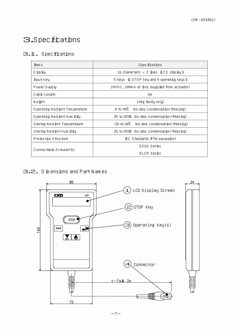
3.Specifications
3.1. Specifications
Items Specifications
Display 16 characters ×2 lines (LCD display)
Input Key 5 keys (1 STOP key and 4 operating keys)
Power Supply 24VDC, 100mA or less (supplied from actuator)
Cable Length 2m
Weight 140g (body only)
Operating Ambient Temperature 0 to 40℃ (no dew condensation/freezing)
Operating Ambient Humidity 35 to 85% (no dew condensation/freezing)
Storing Ambient Temperature -20 to 60℃ (no dew condensation/freezing)
Storing Ambient Humidity 35 to 85% (no dew condensation/freezing)
Protective Structure IEC Standards IP50 equivalent
Connectable Actuator(s) ESSD Series
ELCR Series
3.2. Dimensions and Part Names
1
3
2
4
LCD Display Screen
STOP Key
Operating Key(s)
Connector

<SM-431061>
-8-
① LCD Display Screen
This is a 2-line display with 16 characters maximum per line.
② STOP Key
[STOP] key
This key is used to stop the movements of the actuator.
・Stop
Pressing the STOP key once will stop the movement of the actuator.
The LCD display will indicate STOP as below.
・Undoing stop
Holding down the STOP key for more than 3 seconds will undo the stop, and the actuator
will be in a standby state.
The LCD display will return to the last display before the stop command.
③ Operating Keys
[PUSH] key
This key is used for following operations.
・Selecting menu, parameter, etc.
・Changing values when inputting values
・Moving in PUSH direction when jogging and inching
[PULL] key
This key is used for following operations
・Selecting menu, parameter, etc.
・Changing digits when inputting values
・Moving in PULL direction when jogging and inching
[BACK] key
This key is used to cancel an operation and to return to the previous screen.
[ENTER] key
This key is used to command a menu, to define data, etc.
④ Connector
This connects to the actuator.
>> STOP <<
STOP Indicator

<SM-431061>
-9-
3.3. Functions
(1) List of Functions
There are following functions to the operations executed from the teaching pendant.
Menu
Main Menu Sub-Menu 1 Sub-Menu 2 Functional Overview
Jog
[1.1.1.JOG]
Sets speed and execute “jog” (PUSH/PULL).
Inch
[1.1.2.INCH]
Sets speed and pitch, and execute “inch”
(PUSH/PULL).
Point
[1.1.3.POINT]
Moves to points selected using data
preprogrammed in teaching.
Return-to-Origin
[1.1.4.ORIGIN]
Detects original position and returns to origin.
Movement
[1.1.MOVE]
Servomotor ON/OFF
[1.1.5.SERVO]
Executes ON/OFF of servomotor.
Teaching
[1.2.TEACH]
Sets position, speed, thrust force, acceleration
of each point (7 points maximum).
Parameter Setting
[1.3.1.PARA]
Executes parameter changes.
Movement &
Setting
[1.MOVE&SET]
Parameters
[1.3.PARAMETER]
All Clear
[1.3.2.ALL CLR]
Resets parameters to factory default settings.
Present Position
[2.1.POSITION]
Present position of the actuator can be
identified.
Input/Output
[2.2.IN/OUT]
Condition of the actuator I/O signal can be
confirmed.
Alarm
[2.3.ALARM]
Alarm history can be confirmed.
Model
[2.4.MODEL]
Actuator model can be verified.
Version
[2.5.VERSION]
Driver software version inside the actuator can
be verified.
Monitoring
[2.MONITOR]
Lot/Serial No.
[2.6.LOT/SERIAL]
Lot/serial no. of the actuator can be verified.
Data Saving
[3.1.SAVE]
Actuator data is saved on the teaching
pendant.
Copying
[3.COPY]
Data Writing
[3.2.WRITE]
Data saved on the teaching pendant is written
to the actuator.
※ Sections enclosed with bold lines disable PLC; operations from PLC will be rejected.

<SM-431061>
-10-
(2) Flow of Operations
Operations using the teaching pendant follow the flow below.
※ Sections enclosed with dotted lines disable PLC; operations from PLC will be rejected.
(Basic Operation)
Use and keys to make a selection and
key to fix that selection to proceed to the next screen.
Use key to return to the previous screen.、
Power ON
Main Menu[MAIN MENU]
Movement&Setting
Movement[1.1.MOVE]
Jog [1.1.1.JOG]
Inch[1.1.2.INCH]
Point[1.1.3.POINT]
Return-to-Origin[1.1.4.ORIGIN]
ServomotorON/OFF
Teaching[1.2.TEACH]
Parameters[1.3.PARAMETER]
Parameter Setting[1.3.1.PARA]
All Clear[1.3.2.ALL CLR]
Monitoring[2.MONITOR]
Copying[3.COPY]
Present Position[2.1.POSITION]
Input/Output[2.2.IN/OUT]
Alarm[2.3.ALARM]
Model[2.4.MODEL]
Version[2.5.VERSION]
Lot/Serial No.[2.6.LOT/SERIAL]
Data Saving[3.1.SAVE]
Data Writing[3.2.WRITE]
Initial Display
DriverInformation Read
BACK

<SM-431061>
-11-
4.Operations
4.1. Connecting the Actuator
(1) Connection
Connect the teaching pendant connector on the actuator to the connector on the teaching pendant.
(2) Disconnection
Return to the Main Menu by operating the operating keys on the teaching pendant. Then, disconnect the
connector on the teaching pendant.
※ How to return to the Main Menu
Pressing key will return to the last screen. Repeating this operation will eventually return to the Main
Menu; however, if Enable PLC Confirmation screen appears along the way, press key.
CAUTION
※ Except at the Main Menu, the teaching pendant is constantly passing signals with the actuator. If the teaching
pendant is disconnected while this is going on, it may cause some kind of a malfunction.
Always disconnect at the Main Menu.
BACK
[MAIN MENU] 1/3←1.MOVE&SET →
[MAIN MENU] 2/3←2.MONITOR →
[MAIN MENU] 3/3←3.COPY →
Main Menu
OR
OR、
TP -->PLC ?(Back) (Enter)
Enable PLC Confirmation
<SM-431061>
-12-
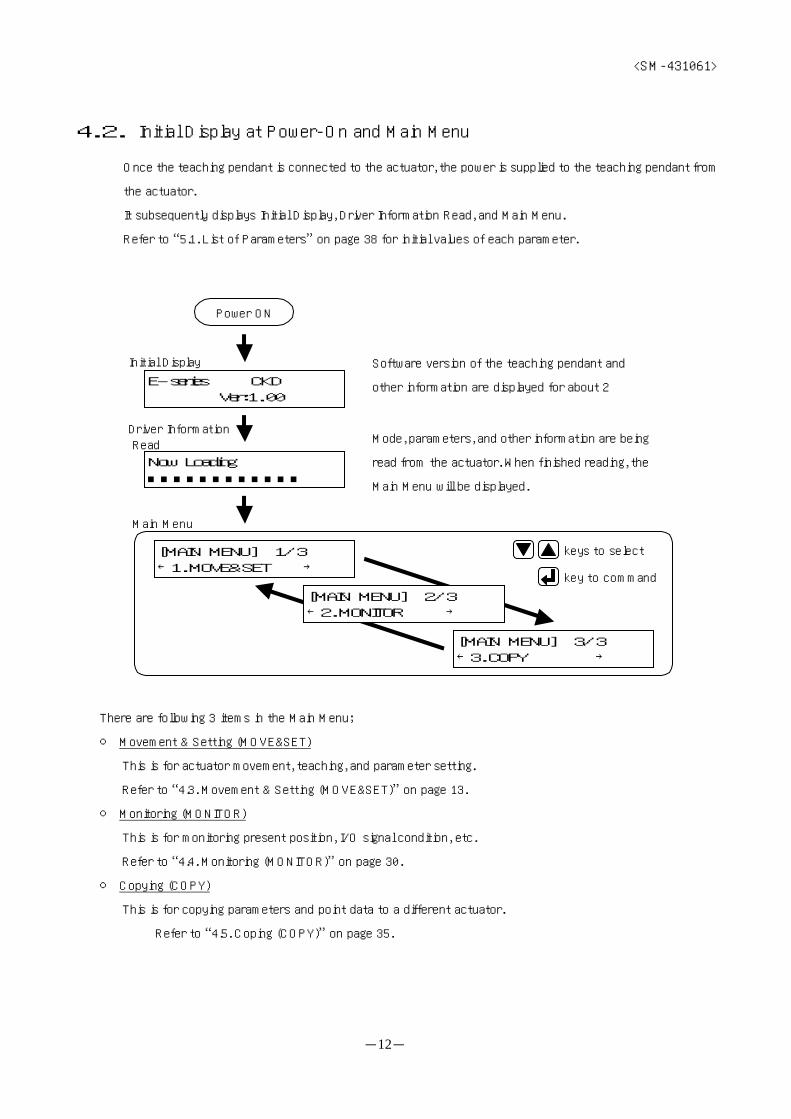
4.2. Initial Display at Power-On and Main Menu
Once the teaching pendant is connected to the actuator, the power is supplied to the teaching pendant from
the actuator.
It subsequently displays Initial Display, Driver Information Read, and Main Menu.
Refer to “5.1. List of Parameters” on page 38 for initial values of each parameter.
There are following 3 items in the Main Menu;
○ Movement & Setting (MOVE&SET)
This is for actuator movement, teaching, and parameter setting.
Refer to “4.3. Movement & Setting (MOVE&SET)” on page 13.
○ Monitoring (MONITOR)
This is for monitoring present position, I/O signal condition, etc.
Refer to “4.4. Monitoring (MONITOR)” on page 30.
○ Copying (COPY)
This is for copying parameters and point data to a different actuator.
Refer to “4.5. Coping (COPY)” on page 35.
Software version of the teaching pendant and
other information are displayed for about 2
Mode, parameters, and other information are being
read from the actuator. When finished reading, the
Main Menu will be displayed.
E-series CKD Ver:1.00
Now Loading■■■■■■■■■■■■
Power ON
Initial Display
Driver Information Read
Main Menu
[MAIN MENU] 3/3←3.COPY →
[MAIN MENU] 1/3←1.MOVE&SET →
keys to select
key to command
[MAIN MENU] 2/3←2.MONITOR →

<SM-431061>
-13-
4.3. Movement & Setting (MOVE&SET)
This is for actuator movement, teaching, and parameter setting.
(※1) Disable PLC Confirmation screen
Press key to disable operations from PLC and switch to MOVE&SET menu.
(※2) Enable PLC Confirmation screen
Press key to enable operations from PLC and return to Main Menu.
There are following 3 items in the MOVE&SET menu;
○ Movement (MOVE)
This is for executing jog, inch, point, return-to-origin, and servomotor ON/OFF movements.
Refer to “4.3.1. Movement (MOVE)” on page 14.
○ Teaching (TEACHING)
This is for setting position, speed, thrust force, and acceleration data of each point.
Refer to “4.3.2. Teaching (TEACHING)” on page 19.
○ Setting the Parameters (PARAMETER)
This is for setting the parameters.
Refer to “4.3.3. Setting the Parameters (PARAMETER)” on page 26.
[MAIN MENU] 1/3←1.MOVE&SET →
Main Menu
PLC -->TP ?(Back) (Enter)
Disable PLC Confirmation
MOVE&SET Menu
[1.MOVE&SET] 3/3←1.3.PARAMETER →
[1.MOVE&SET] 1/3←1.1.MOVE →
BACK
TP -->PLC ?(Back) (Enter)
Enable PLC Confirmation
[1.MOVE&SET] 2/3←1.2.TEACHING →
keys to select
key to command
(※1) (※2)
<SM-431061>
-14-
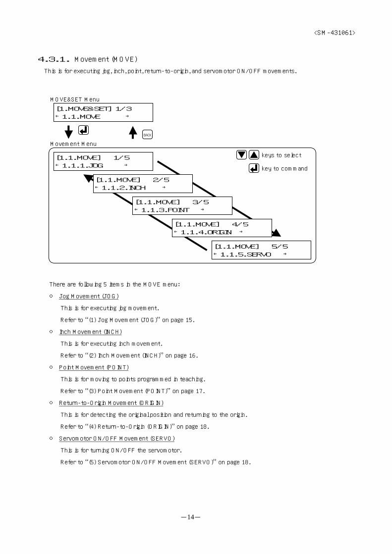
4.3.1. Movement (MOVE)
This is for executing jog, inch, point, return-to-origin, and servomotor ON/OFF movements.
There are following 5 items in the MOVE menu:
○ Jog Movement (JOG)
This is for executing jog movement.
Refer to “(1) Jog Movement (JOG)” on page 15.
○ Inch Movement (INCH)
This is for executing inch movement.
Refer to “(2) Inch Movement (INCH)” on page 16.
○ Point Movement (POINT)
This is for moving to points programmed in teaching.
Refer to “(3) Point Movement (POINT)” on page 17.
○ Return-to-Origin Movement (ORIGIN)
This is for detecting the original position and returning to the origin.
Refer to “(4) Return-to-Origin (ORIGIN)” on page 18.
○ Servomotor ON/OFF Movement (SERVO)
This is for turning ON/OFF the servomotor.
Refer to “(5) Servomotor ON/OFF Movement (SERVO)” on page 18.
[1.MOVE&SET] 1/3←1.1.MOVE →
MOVE&SET Menu
Movement Menu
[1.1.MOVE] 1/5←1.1.1.JOG →
[1.1.MOVE] 5/5←1.1.5.SERVO →
[1.1.MOVE] 3/5←1.1.3.POINT →
[1.1.MOVE] 2/5←1.1.2.INCH →
[1.1.MOVE] 4/5←1.1.4.ORIGIN →
BACK
keys to select
key to command

<SM-431061>
-15-
(1) Jog Movement (JOG)
This is for setting jogging speed and executing jog movement.
※ Assignable values for jogging speed vary depending on the actuator being used.
Refer to “6.1. Table 6.1: Transfer Speed” on page 40.
Start jog movement with key or key.
The screen will change to Jogging screen
Set jogging speed with key or key.
(※)
Stop jogging by releasing the key.
The screen will return to Jog Movement screen.
(※) When the servomotor is OFF, Servomotor ON Confirmation screen will appear.
Press key to turn ON the servomotor.
[1.1.MOVE] 1/5←1.1.1.JOG →
Movement Menu
[1.1.1.JOG] 050<■■■■■ >mm/s
[1.1.1.JOG] (Pull / Push)
Jogging Speed Setting
Jog Movement
[1.1.1.JOG]>>MOVING ! <<
Jogging
BACK
BACK

<SM-431061>
-16-
(2)Inch Movement (INCH)
This is for setting inching speed and pitch and executing inch movement
※ Assignable values for inching speed vary depending on the actuator being used.
Refer to “6.1. Table 6.1: Transfer Speed” on page 40.
※ Assignable values for inching pitch vary depending on the actuator being used.
Refer to “6.4. Table 6.4: Inching Pitch” on page 40.)
Start inch movement with key or key.
The screen will change to Inching screen.
Set inching speed with key or key.
Set inching pitch with key or key
(※)
(※) When the servomotor is OFF, Servomotor ON Confirmation screen will appear.
Press key to turn ON the servomotor
After moving in set pitches, the screen will return to Inch
Movement screen.
[1.1.MOVE] 2/5←1.1.2.INCH →
Movement Menu
[1.1.2.INCH] 050<■■■■■ >mm/s
[1.1.2.INCH] (Pull / Push)
Inching Speed Setting
Inch Movement
[1.1.2.INCH]>>MOVING ! <<
Inching
BACK
BACK
[1.1.2.INCH]10.0<■■■■■■■■ > mm
Inching Pitch Setting
BACK
<SM-431061>
-17-
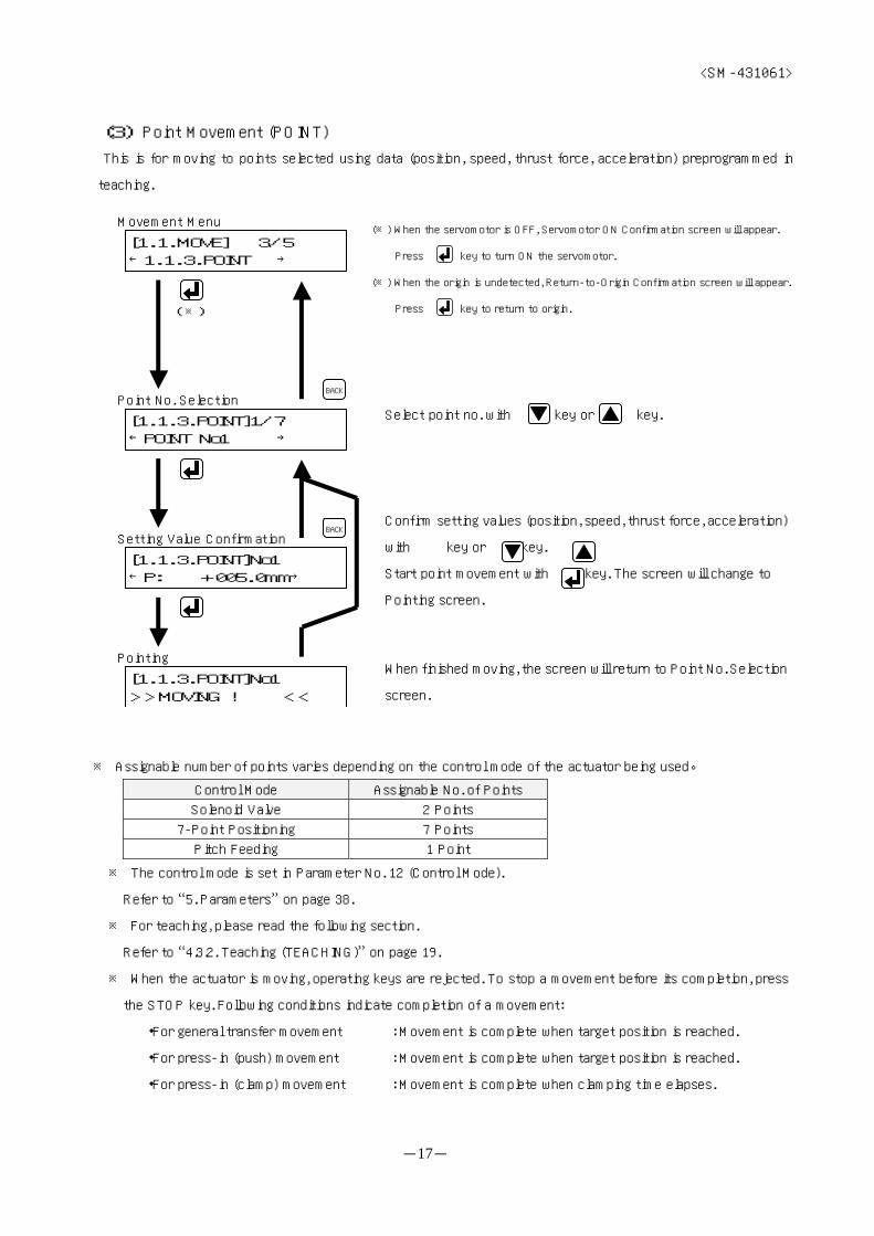
(3) Point Movement (POINT)
This is for moving to points selected using data (position, speed, thrust force, acceleration) preprogrammed in
teaching.
※ Assignable number of points varies depending on the control mode of the actuator being used。
Control Mode Assignable No. of Points
Solenoid Valve 2 Points
7-Point Positioning 7 Points
Pitch Feeding 1 Point
※ The control mode is set in Parameter No. 12 (Control Mode).
Refer to “5. Parameters” on page 38.
※ For teaching, please read the following section.
Refer to “4.3.2. Teaching (TEACHING)” on page 19.
※ When the actuator is moving, operating keys are rejected. To stop a movement before its completion, press
the STOP key. Following conditions indicate completion of a movement:
・For general transfer movement : Movement is complete when target position is reached.
・For press-in (push) movement : Movement is complete when target position is reached.
・For press-in (clamp) movement : Movement is complete when clamping time elapses.
(※)
Select point no. with key or key.
Confirm setting values (position, speed, thrust force, acceleration)
with key or key.
Start point movement with key. The screen will change to
Pointing screen.
When finished moving, the screen will return to Point No. Selection
screen.
(※) When the servomotor is OFF, Servomotor ON Confirmation screen will appear.
Press key to turn ON the servomotor.
(※) When the origin is undetected, Return-to-Origin Confirmation screen will appear.
Press key to return to origin.
[1.1.MOVE] 3/5←1.1.3.POINT →
Movement Menu
[1.1.3.POINT]1/7←POINT No1 →
Point No. Selection
[1.1.3.POINT]No1>>MOVING ! <<
Pointing
BACK
BACK
[1.1.3.POINT]No1←P: +005.0mm→
Setting Value Confirmation

<SM-431061>
-18-
(4) Return-to-Origin Movement (ORIGIN)
This is for detecting the original position and returning to the origin
(5) Servomotor ON/OFF Movement (SERVO)
This is for turning ON/OFF the servomotor.
(※) When the servomotor is OFF, Servomotor ON Confirmation screen will appear.
Press key to turn ON the servomotor.
Start return-to-origin movement with key. The screen will
change to Returning-to-Origin screen
When the return-to-origin is complete, the screen will return to
MOVE Menu。
When the servomotor is ON, Servomotor OFF Confirmation
screen will appear.
Press key to turn OFF the servomotor
When the servomotor is OFF, Servomotor ON Confirmation
screen will appear.
Press key to turn ON the servomotor.
(※)
[1.1.MOVE] 4/5←1.1.4.ORIGIN →
Movement Menu
[1.1.4.ORIGIN]Go to ORIGIN ?
Return-to-Origin Confirmation
[1.1.4.ORIGIN]>>MOVING ! <<
Returning-to-Origin
BACK
[1.1.MOVE] 5/5←1.1.5.SERVO →
Movement Menu
Servomotor OFF Confirmation
BACK
[1.1.5.SERVO]SERVO OFF-->ON ?
Servomotor ON Confirmation
[1.1.5.SERVO]SERVO ON-->OFF ?
Servomotor ON/OFF Confirmation

<SM-431061>
-19-
4.3.2. Teaching (TEACHING)
This is for setting position, speed, thrust force, and acceleration data of each point.
(1) Point No. and Setup Item Selection
※ Assignable number of points varies depending on the control mode of the actuator being used
Control Mode Assignable No. of Points
Solenoid Valve 2 Points
7-Point Positioning 7 Points
Pitch Feeding 1 Point
※ The control mode is set in Parameter No. 12 (Control Mode).
Refer to “5. Parameters” on page 38.
There are following 4 setup items.
○ Position Setting (P) Refer to “(2) Position Setting (P)” on page 20.
○ Speed Setting (V) Refer to “(3) Speed Setting (P)” on page 24.
○ Thrust Force Setting (F) Refer to “(4) Thrust Force Setting (P)” on page 25.
Acceleration Setting (A) Refer to “(5) Acceleration Setting (P)” on page 25.
Select point no. with key or key.
[1.MOVE&SET] 2/3←1.2.TEACHING →
MOVE&SET Menu
[1.2.TEACH] 2/7←POINT No2 →
Point No. SelectionBACK
BACK
Setup Item Selection
[1.2.TEACH] No2←P: +010.0mm→
[1.2.TEACH] No2←V: 100mm/s→
[1.2.TEACH] No2←F:PUSH 50%→
[1.2.TEACH] No2←A: 2.0m/s2→
keys to select
key to command
<SM-431061>
-20-
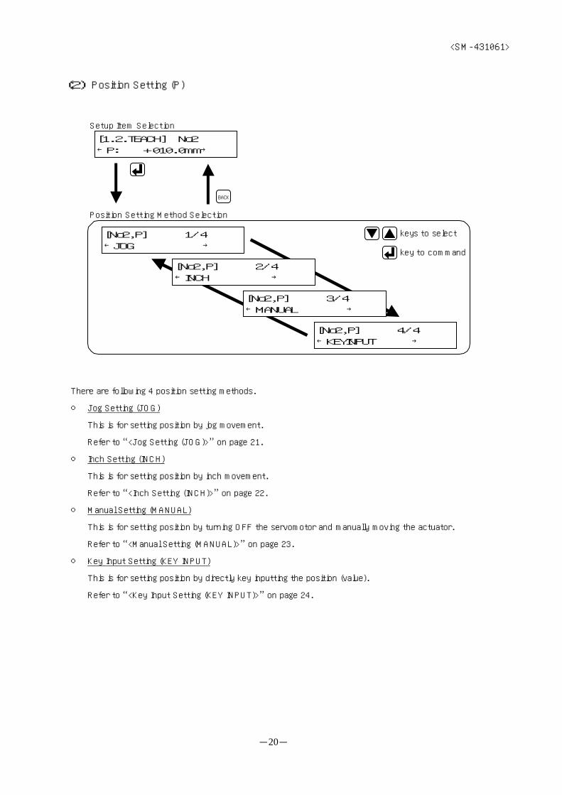
(2) Position Setting (P)
There are following 4 position setting methods.
○ Jog Setting (JOG)
This is for setting position by jog movement.
Refer to “<Jog Setting (JOG)>” on page 21.
○ Inch Setting (INCH)
This is for setting position by inch movement.
Refer to “<Inch Setting (INCH)>” on page 22.
○ Manual Setting (MANUAL)
This is for setting position by turning OFF the servomotor and manually moving the actuator.
Refer to “<Manual Setting (MANUAL)>” on page 23.
○ Key Input Setting (KEY INPUT)
This is for setting position by directly key inputting the position (value).
Refer to “<Key Input Setting (KEY INPUT)>” on page 24.
[1.2.TEACH] No2←P: +010.0mm→
Setup Item Selection
Position Setting Method Selection
[No2,P] 1/4←JOG →
[No2,P] 2/4←INCH →
[No2,P] 3/4←MANUAL →
[No2,P] 4/4←KEYINPUT →
keys to select
key to command
BACK
<SM-431061>
-21-
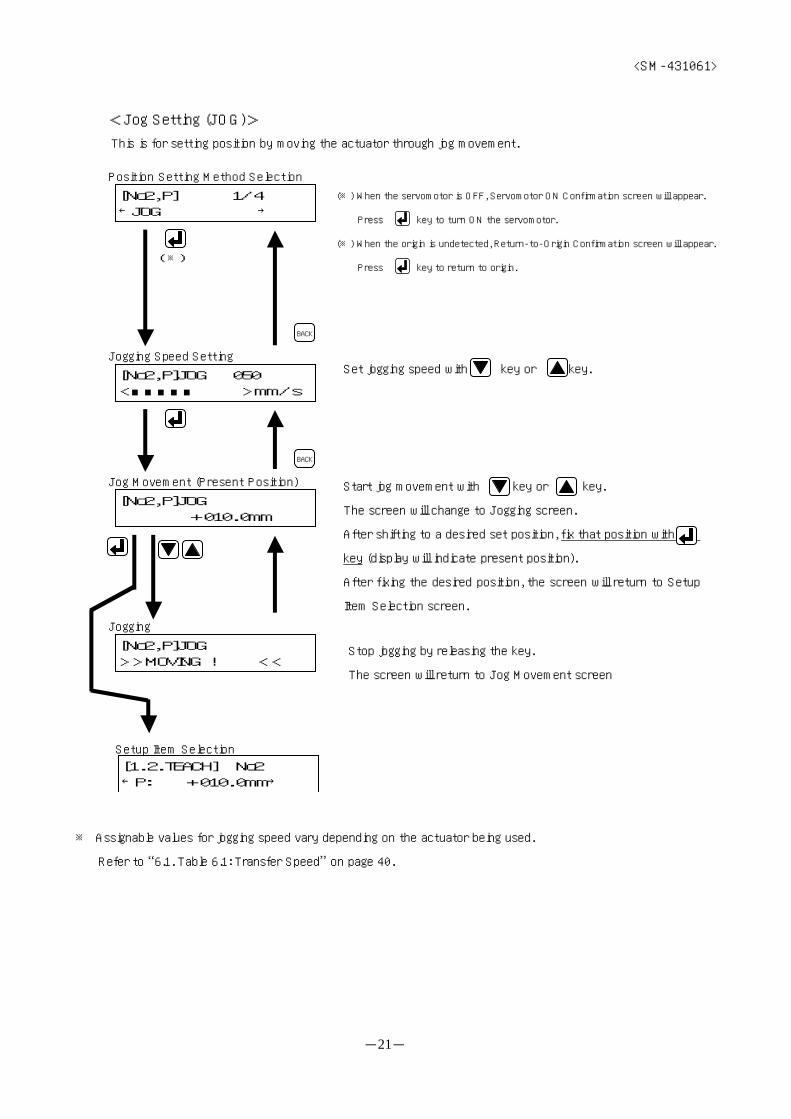
<Jog Setting (JOG)>
This is for setting position by moving the actuator through jog movement.
※ Assignable values for jogging speed vary depending on the actuator being used.
Refer to “6.1. Table 6.1: Transfer Speed” on page 40.
Start jog movement with key or key.
The screen will change to Jogging screen.
After shifting to a desired set position, fix that position with
key (display will indicate present position).
After fixing the desired position, the screen will return to Setup
Item Selection screen.
(※)
(※) When the servomotor is OFF, Servomotor ON Confirmation screen will appear.
Press key to turn ON the servomotor.
(※) When the origin is undetected, Return-to-Origin Confirmation screen will appear.
Press key to return to origin.
Set jogging speed with key or key.
Stop jogging by releasing the key.
The screen will return to Jog Movement screen
[No2,P] 1/4←JOG →
[No2,P]JOG 050<■■■■■ >mm/s
Jogging Speed Setting
BACK
BACK
[No2,P]JOG +010.0mm
Position Setting Method Selection
Jog Movement (Present Position)
[No2,P]JOG>>MOVING ! <<
Jogging
[1.2.TEACH] No2←P: +010.0mm→
Setup Item Selection

<SM-431061>
-22-
<Inch Setting (INCH)>
This is for setting position by moving the actuator through inch movement.
※ Assignable values for inching speed vary depending on the actuator being used.
Refer to “6.1. Table 6.1: Transfer Speed” on page 40.
※ Assignable values for inching pitch vary depending on the actuator being used.
Refer to “6.4. Table 6.4: Inching Pitch” on page 40.
Start inch movement with key or key.
The screen will change to Inching screen.
After shifting to a desired set position, fix that position with
key (display will indicate present position).
After fixing the desired position, the screen will return to Setup
Item Selection screen.
(※)
(※) When the servomotor is OFF, Servomotor ON Confirmation screen will appear.
Press key to turn ON the servomotor.
(※) When the origin is undetected, Return-to-Origin Confirmation screen will appear.
Press key to return to origin.
Set inching speed with key or key.
After moving in set pitches, the screen will return to Inch
Movement screen
Set inching pitch with key or key.
[No2,P] 2/4←INCH →
[No2,P]INCH 050<■■■■■ >mm/s
Inching Speed Setting
BACK
BACK
[No2,P]INCH +010.0mm
Position Setting Method Selection
Inch Movement (Present Position)
[No2,P]INCH>>MOVING ! <<
Inching
[No2,P]INCH 10.0<■■■■■■■■ > mm
Inching Pitch Setting
BACK
[1.2.TEACH] No2←P: +010.0mm→
Setup Item Selection
<SM-431061>
-23-
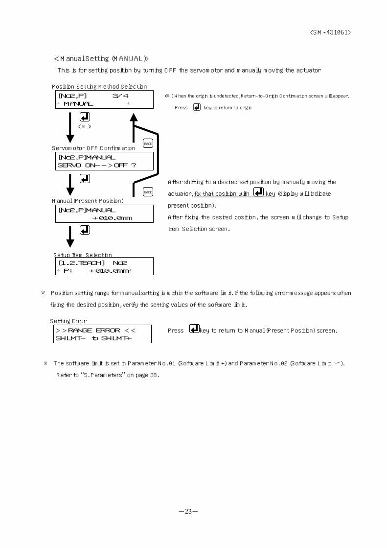
<Manual Setting (MANUAL)>
This is for setting position by turning OFF the servomotor and manually moving the actuator
※ Position setting range for manual setting is within the software limit. If the following error message appears when
fixing the desired position, verify the setting values of the software limit.
※ The software limit is set in Parameter No. 01 (Software Limit +) and Parameter No. 02 (Software Limit ー).
Refer to “5. Parameters” on page 38.
Press key to return to Manual (Present Position) screen.
(※) When the origin is undetected, Return-to-Origin Confirmation screen will appear.
Press key to return to origin
(※)
After shifting to a desired set position by manually moving the
actuator, fix that position with key (display will indicate
present position).
After fixing the desired position, the screen will change to Setup
Item Selection screen.
Setting Error
>>RANGE ERROR <<SWLMT- to SWLMT+
[No2,P]MANUALSERVO ON-->OFF ?
Servomotor OFF ConfirmationBACK
Position Setting Method Selection
[No2,P] 3/4←MANUAL →
[No2,P]MANUAL +010.0mm
Manual (Present Position)
BACK
[1.2.TEACH] No2←P: +010.0mm→
Setup Item Selection

<SM-431061>
-24-
<Key Input Setting (KEY INPUT)>
This is for setting position by directly key inputting the position (value)
※ For key input setting, position setting range is within the software limit. If the following error message appears
when fixing the desired position, verify the setting values of the software limit
※ The software limit is set in Parameter No. 01 (Software Limit +) and Parameter No. 02 (Software Limit ー).
Refer to “5. Parameters” on page 38.
(3) Speed Setting (V)
※ Assignable values for speed vary depending on the actuator being used.
Refer to “6.1. Table 6.1: Transfer Speed” on page 40.
Press key to return to Manual (Present Position) screen.
Set speed with key or key.
Use key to select the digits to change. (Digits selected will blink.)
Use key to change the value.
Use key to fix the position.
After fixing the position, the screen will change to Setup Item Selection
screen.
[No2,P]KEYINPUT +010.0mm
Key InputBACK
Position Setting Method Selection
[No2,P] 4/4←KEYINPUT →
BACK
[1.2.TEACH] No2←P: +010.0mm→
Setup Item Selectio
Setting Error
>>RANGE ERROR <<SWLMT- to SWLMT+
[1.2.TEACH] No2←V: 100mm/s→
Setup Item Selection
[No2,V] 100<■■■■■■■■■■>mm/
Speed SettingBACK

<SM-431061>
-25-
(4)Thrust Force Setting (F)
※ NO PRESS display indicates general transfer movement.
※ PUSH and value (%) display indicates press-in (push) movement.
※ CLAMP and value (%) display indicates press-in (clamp) movement.
※ Value (%) indicates current-limiting value of the motor, and its assignable values vary depending on the press-in
mode (push, clamp).
Thrust Mode Assignable Values[%]
PUSH (Push) 50,61,75,82,100
CLAMP (Clamp) 50,61,75,82
※ The press-in mode is set in Parameter No. 07 (Press-in Mode).
Refer to “5. Parameters” on page 38.
※ Setting different press-in mode at each point is not allowed.
Example) Setting first point as push and second point as clamp is not allowed.
(5) Acceleration Setting (A)
※ Deceleration will have the same value as acceleration.
※ Assignable values for acceleration vary depending on the actuator being used.
Refer to “6.3. Table 6.3: Acceleration” on page 40.
Set thrust force with key or key.
Set acceleration with key or key.
[1.2.TEACH] No2←F:PUSH 50%→
Setup Item Selection
[No2,F]PUSH 050<■■ > %
Thrust Force SettingBACK
[1.2.TEACH] No2←A: 2.0m/s2→
Setup Item Selection
[No2,A] 2.0<■■■■■■■■■■>m/s
Acceleration SettingBACK

<SM-431061>
-26-
4.3.3. Setting the Parameters (PARAMETER)
There are following 2 items in the Parameter Menu.
○ Parameter Setting (PARA)
This is for parameter setting.
Refer to “(1) Parameter Setting (PARA)” on page 27.
○ All Clear (ALL CLR)
This is for resetting parameters and point data to factory default values.
It will be necessary to re-execute return-to-origin since this will cause the origin to be undetected.
Refer to “(2) All Clear (ALL CLR)” on page 29.
[1.MOVE&SET] 3/3←1.3.PARAMETER →
MOVE&SET Menu
Parameter Menu
[1.3.PARA] 1/2←1.3.1.PARA →
[1.3.PARA] 2/2←1.3.2.ALL CLR →
keys to select key to command
BACK

<SM-431061>
-27-
(1)Parameter Setting (PARA)
[1.3.PARA] 1/2←1.3.1.PARA →
Parameter Menu
BACK
[1.3.1.PARA]←01:S/W LIMIT+ →
Parameter Selection
keys to select
[1.3.1.PARA]←14:PITCHING P →
[1.3.1.PARA]←12:OPE MODE →
[1.3.1.PARA]←02:S/W LIMIT- →
[1.3.1.PARA]←03:INPOSITION →
[1.3.1.PARA]←11:AUTO ALMRST→
[1.3.1.PARA]←13:VALVE MODE →
01:S/W LIMIT++050.0mm
Parameter Setting
BACK
※ For setting speed,
use key or key to set and use key to fix it.
Use key to select the digits to change.
(Digits selected will blink.)
Use key to change the value.
Use key to fix the value.
After fixing the value, the screen will return to Parameter Selection screen.
<SM-431061>
-28-
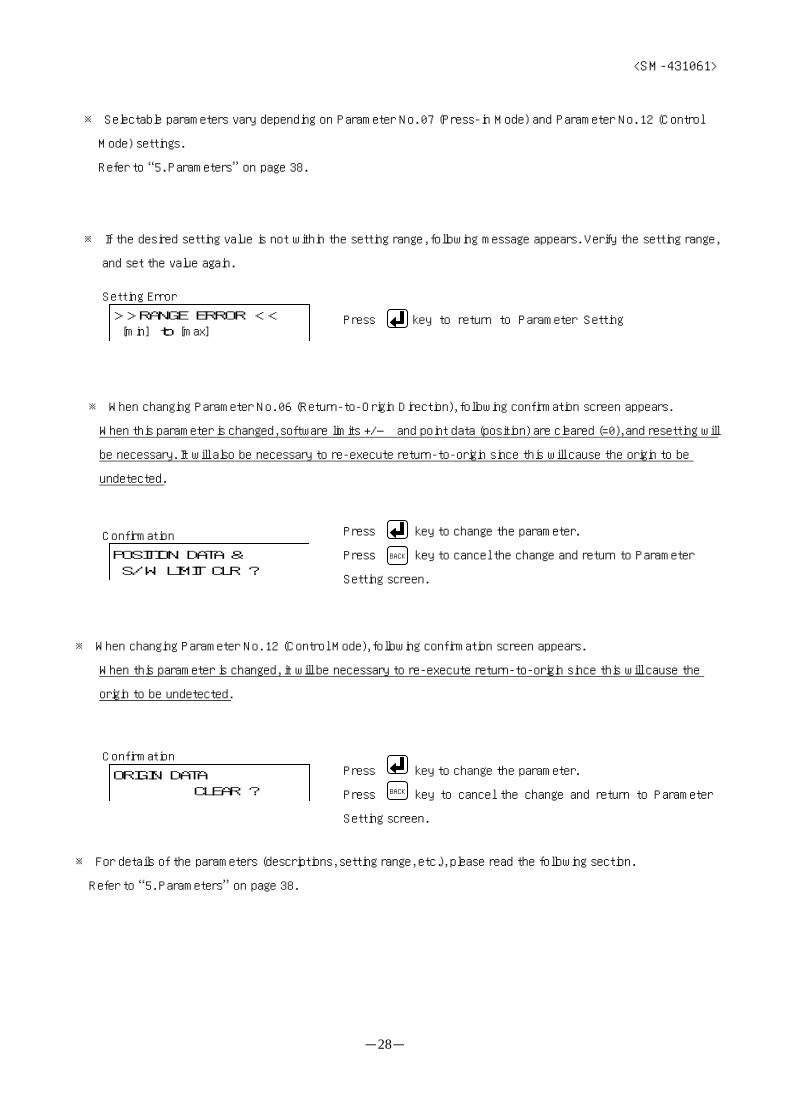
※ Selectable parameters vary depending on Parameter No. 07 (Press-in Mode) and Parameter No. 12 (Control
Mode) settings.
Refer to “5. Parameters” on page 38.
※ If the desired setting value is not within the setting range, following message appears. Verify the setting range,
and set the value again.
※ When changing Parameter No. 06 (Return-to-Origin Direction), following confirmation screen appears.
When this parameter is changed, software limits +/― and point data (position) are cleared (=0), and resetting will
be necessary. It will also be necessary to re-execute return-to-origin since this will cause the origin to be
undetected.
※ When changing Parameter No. 12 (Control Mode), following confirmation screen appears.
When this parameter is changed, it will be necessary to re-execute return-to-origin since this will cause the
origin to be undetected.
※ For details of the parameters (descriptions, setting range, etc.), please read the following section.
Refer to “5. Parameters” on page 38.
Press key to return to Parameter Setting
Press key to change the parameter.
Press key to cancel the change and return to Parameter
Setting screen.
BACK
Press key to change the parameter.
Press key to cancel the change and return to Parameter
Setting screen.
BACK
Setting Error
>>RANGE ERROR << [min] to [max]
POSITION DATA & S/W LIMIT CLR ?
Confirmation
ORIGIN DATA CLEAR ?
Confirmation
<SM-431061>
-29-
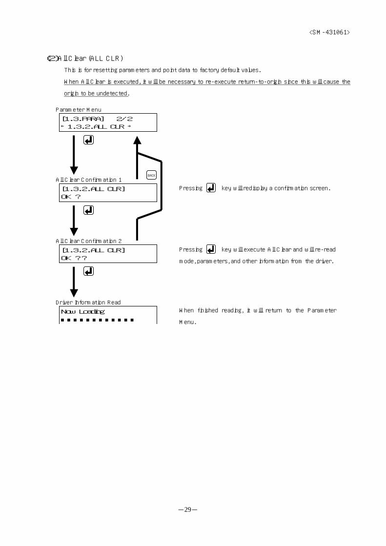
(2)All Clear (ALL CLR)
This is for resetting parameters and point data to factory default values.
When All Clear is executed, it will be necessary to re-execute return-to-origin since this will cause the
origin to be undetected.
Pressing key will execute All Clear and will re-read
mode, parameters, and other information from the driver.
Pressing key will redisplay a confirmation screen.
When finished reading, it will return to the Parameter
Menu.
[1.3.PARA] 2/2←1.3.2.ALL CLR →
Parameter Menu
[1.3.2.ALL CLR]OK ?
[1.3.2.ALL CLR]OK ??
All Clear Confirmation 1
All Clear Confirmation 2
BACK
Now Loading■■■■■■■■■■■■
Driver Information Read

<SM-431061>
-30-
4.4. Monitoring (MONITOR)
This is for monitoring present position, I/O signal condition, etc.
There are following 6 items in the Monitoring Menu.
○ Present Position (POSITION)
This displays present position of the actuator.
Refer to “(1) Present Position (POSITION)” on page 31.
○ Input/Output (IN/OUT)
This displays I/O signal condition of the actuator.
Refer to “(2) Input/Output (IN/OUT)” on page 31.
○ Alarm (ALARM)
This displays alarm information.
Refer to “(3) Alarm (ALARM)” on page 32.
○ Model (MODEL)
This displays model of the actuator.
Refer to “(4) Model (MODEL)” on page 33.
Main Menu
keys to select
key to command
[MAIN MENU] 2/3←2.MONITOR →
[2.MONITOR] 1/6←2.1.POSITION →
[2.MONITOR] 2/6←2.2.IN/OUT →
[2.MONITOR] 3/6←2.3.ALARM →
[2.MONITOR] 4/6←2.4.MODEL →
[2.MONITOR] 5/6←2.5.VERSION →
[2.MONITOR] 6/6←2.6.LOT/SERIAL→
BACK
Monitoring Menu
<SM-431061>
-31-
○ Version (VERSION)
This displays driver software version inside the actuator.
Refer to “(5) Version (VERSION)” on page 33.
○ Lot/Serial No. (LOT/SERIAL)
This displays lot no. and serial no. of the actuator.
Refer to “(6) Lot/Serial No. (LOT/SERIAL)” on page 34.
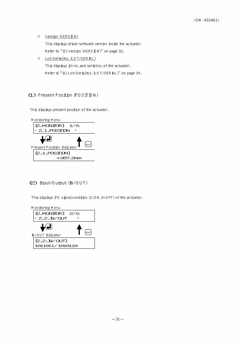
(1) Present Position (POSITION)
This displays present position of the actuator.
(2) Input/Output (IN/OUT)
This displays I/O signal condition (1: ON, 0: OFF) of the actuator.
[2.MONITOR] 1/6←2.1.POSITION →
Monitoring Menu
[2.1.POSITION] +087.2mm
Present Position IndicatorBACK
Monitoring Menu
[2.2.IN/OUT]1011011/1010110
IN/OUT IndicatorBACK
[2.MONITOR] 2/6←2.2.IN/OUT →
<SM-431061>
-32-
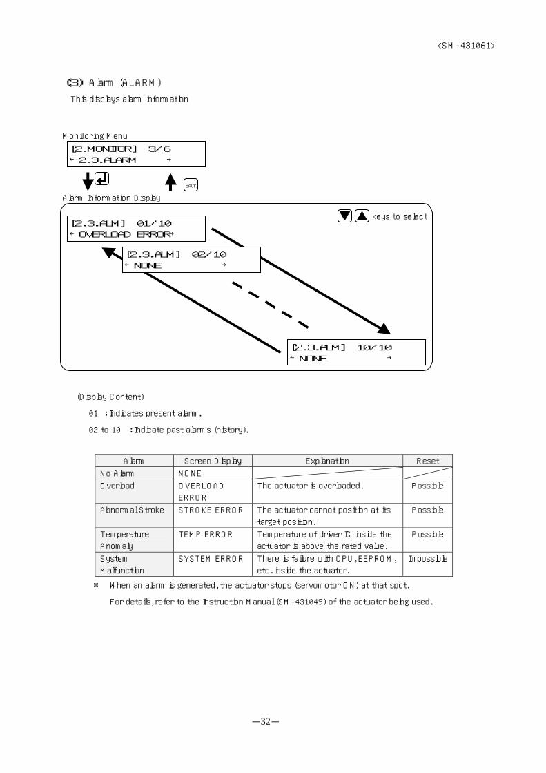
(3) Alarm (ALARM)
This displays alarm information
(Display Content)
01 : Indicates present alarm.
02 to 10 : Indicate past alarms (history).
Alarm Screen Display Explanation Reset
No Alarm NONE
Overload OVERLOAD
ERROR
The actuator is overloaded. Possible
Abnormal Stroke STROKE ERROR The actuator cannot position at its
target position.
Possible
Temperature
Anomaly
TEMP ERROR Temperature of driver IC inside the
actuator is above the rated value.
Possible
System
Malfunction
SYSTEM ERROR There is failure with CPU, EEPROM,
etc. inside the actuator.
Impossible
※ When an alarm is generated, the actuator stops (servomotor ON) at that spot.
For details, refer to the Instruction Manual (SM-431049) of the actuator being used.
Monitoring Menu
[2.3.ALM] 01/10←OVERLOAD ERROR→
Alarm Information Display
BACK
[2.MONITOR] 3/6←2.3.ALARM →
[2.3.ALM] 10/10←NONE →
[2.3.ALM] 02/10←NONE →
keys to select
<SM-431061>
-33-
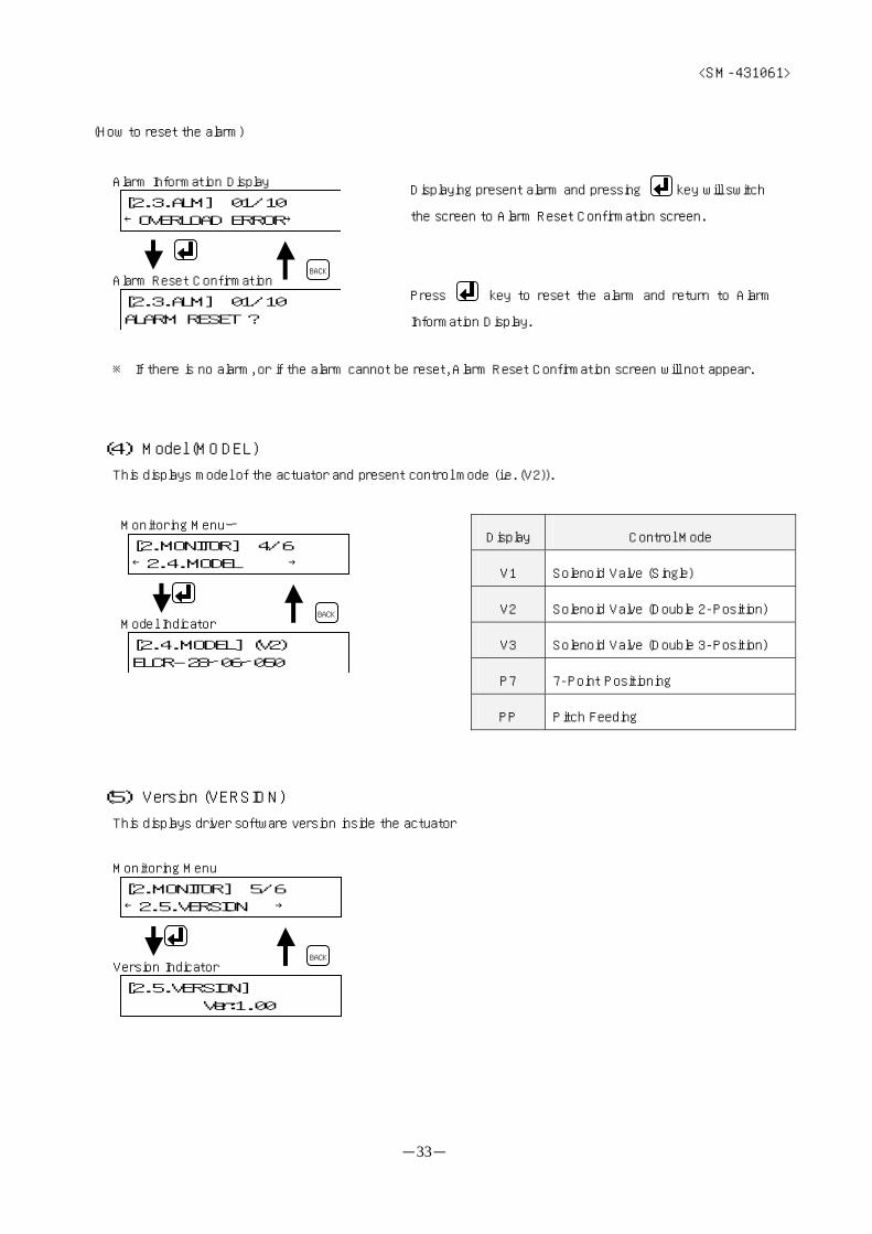
(How to reset the alarm)
※ If there is no alarm, or if the alarm cannot be reset, Alarm Reset Confirmation screen will not appear.
(4) Model (MODEL)
This displays model of the actuator and present control mode (i.e. (V2)).
Display Control Mode
V1 Solenoid Valve (Single)
V2 Solenoid Valve (Double 2-Position)
V3 Solenoid Valve (Double 3-Position)
P7 7-Point Positioning
PP Pitch Feeding
(5) Version (VERSION)
This displays driver software version inside the actuator
Displaying present alarm and pressing key will switch
the screen to Alarm Reset Confirmation screen.
Press key to reset the alarm and return to Alarm
Information Display.
Monitoring Menuー
[2.4.MODEL] (V2)ELCR-28ー06ー050
Model IndicatorBACK
[2.MONITOR] 4/6←2.4.MODEL →
[2.3.ALM] 01/10←OVERLOAD ERROR→
[2.3.ALM] 01/10ALARM RESET ?
Alarm Information Display
Alarm Reset ConfirmationBACK
Monitoring Menu
[2.5.VERSION] Ver:1.00
Version IndicatorBACK
[2.MONITOR] 5/6←2.5.VERSION →
<SM-431061>
-34-
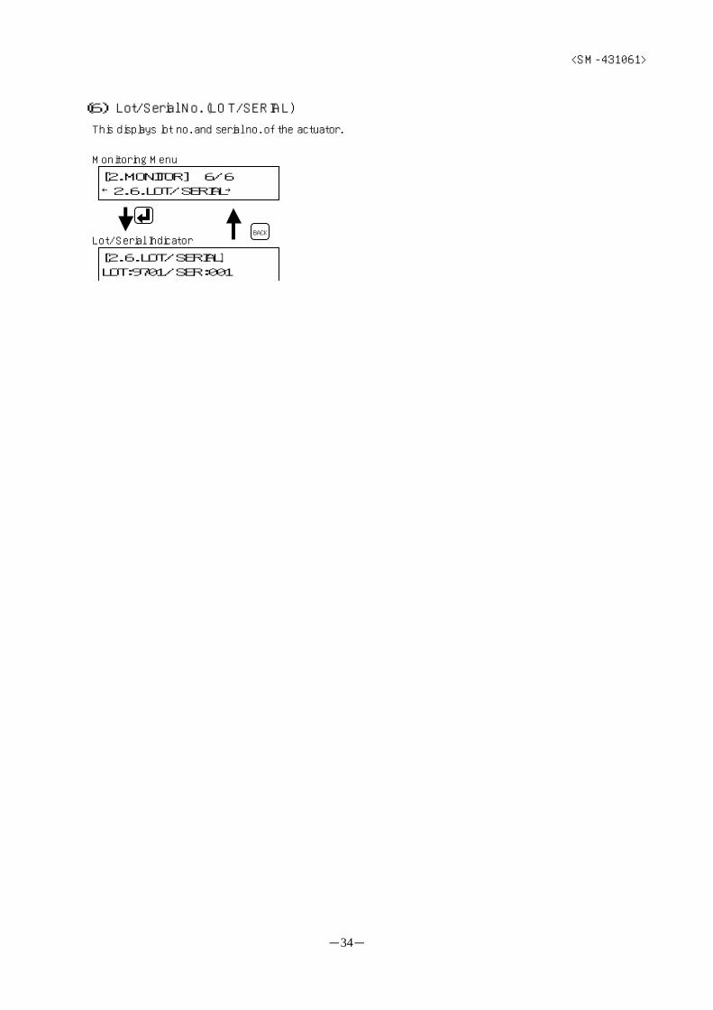
(6) Lot/Serial No. (LOT/SERIAL)
This displays lot no. and serial no. of the actuator.
Monitoring Menu
[2.6.LOT/SERIAL]LOT:9701/SER:001
Lot/Serial IndicatorBACK
[2.MONITOR] 6/6←2.6.LOT/SERIAL→

<SM-431061>
-35-
4.5.Copying (COPY)
This is for copying parameters and point data to a different actuator.
There are following 2 items in the Copying Menu.
○ Data Saving (SAVE)
This is for saving parameters and point data to the teaching pendant.
Refer to “(1) Data Saving (SAVE)” on page 36.
○ Data Writing (WRITE)
This is for writing parameters and point data saved on the teaching pendant to the actuator.
Refer to “(2) Data Writing (WRITE)” on page 37.
[MAIN MENU] 3/3←3.COPY →
Main Menu
Copying Menu
[3.COPY] 1/2←3.1.SAVE →
[3.COPY] 2/2←3.2.WRITE →
keys to select key to command
BACK
<SM-431061>
-36-
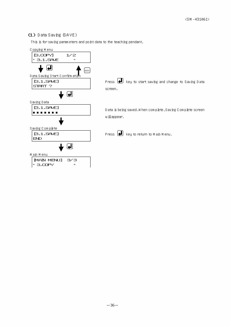
(1) Data Saving (SAVE)
This is for saving parameters and point data to the teaching pendant.
Press key to start saving and change to Saving Data
screen.
Data is being saved. When complete, Saving Complete screen
will appear.
Press key to return to Main Menu.
[3.COPY] 1/2←3.1.SAVE →
Copying Menu
[3.1.SAVE]START ?
Data Saving Start Confirmation
[3.1.SAVE]■■■■■■■
Saving Data
[3.1.SAVE]END
Saving Complete
BACK
[MAIN MENU] 3/3←3.COPY →
Main Menu

<SM-431061>
-37-
(2) Data Writing (WRITE)
This is for writing parameters and point data saved on the teaching pendant to the actuator.
※ Data writing is possible only when motor size, lead length, and stroke all correspond.
※ It is necessary to reject operations from PLC by disabling PLC because parameters and point data are changed
during data writing.
Press key to switch to Disable PLC Confirmation
screen.
Data is being saved. When complete, Saving Complete
screen will appear.
Press key to switch to Enable PLC Confirmation
screen.
Press key to disable PLC and start saving.
Press key to enable PLC and return to Main Menu
Copying Menu
[3.2.WRITE]START ?
Data Saving Start Confirmation
BACK
[3.COPY] 2/2←3.2.WRITE →
PLC -->TP ?(Back) (Enter)
Disable PLC Confirmation
TP -->PLC ?(Back) (Enter)
Enable PLC Confirmation
[3.2.WRITE]■■■■■■■
Saving Data
[3.2.WRITE]END
Saving Complete
[MAIN MENU] 3/3←3.COPY →
Main Menu
<SM-431061>
-38-
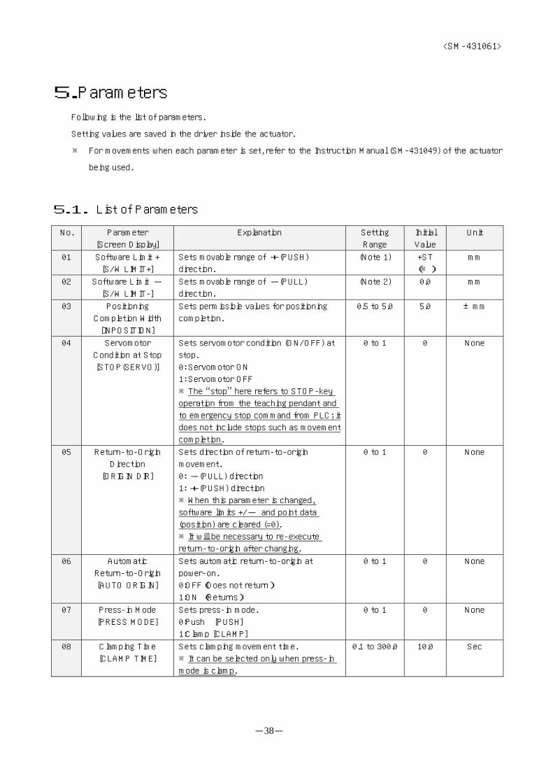
5.Parameters Following is the list of parameters.
Setting values are saved in the driver inside the actuator.
※ For movements when each parameter is set, refer to the Instruction Manual (SM-431049) of the actuator
being used.
5.1. List of Parameters
No. Parameter
[Screen Display]
Explanation Setting
Range
Initial
Value
Unit
01 Software Limit +
[S/W LIMIT+]
Sets movable range of +(PUSH)
direction.
(Note 1) +ST
(※)
mm
02 Software Limit -
[S/W LIMIT-]
Sets movable range of -(PULL)
direction.
(Note 2) 0.0 mm
03 Positioning
Completion Width
[INPOSITION]
Sets permissible values for positioning
completion.
0.5 to 5.0 5.0 ±mm
04 Servomotor
Condition at Stop
[STOP(SERVO)]
Sets servomotor condition (ON/OFF) at
stop.
0: Servomotor ON
1: Servomotor OFF
※The “stop” here refers to STOP-key
operation from the teaching pendant and
to emergency stop command from PLC; it
does not include stops such as movement
completion.
0 to 1 0 None
05 Return-to-Origin
Direction
[ORIGIN DIR]
Sets direction of return-to-origin
movement.
0: -(PULL) direction
1: +(PUSH) direction
※When this parameter is changed,
software limits +/- and point data
(position) are cleared (=0).
※It will be necessary to re-execute
return-to-origin after changing.
0 to 1 0 None
06 Automatic
Return-to-Origin
[AUTO ORIGIN]
Sets automatic return-to-origin at
power-on.
0:OFF(Does not return)
1:ON (Returns)
0 to 1 0 None
07 Press-in Mode
[PRESS MODE]
Sets press-in mode.
0:Push [PUSH]
1:Clamp [CLAMP]
0 to 1 0 None
08 Clamping Time
[CLAMP TIME]
Sets clamping movement time.
※It can be selected only when press-in
mode is clamp.
0.1 to 300.0 10.0 Sec
<SM-431061>
-39-
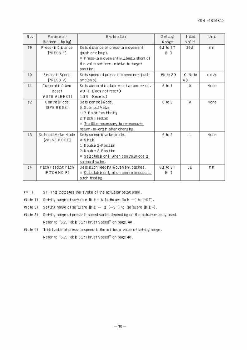
No. Parameter
[Screen Display]
Explanation Setting
Range
Initial
Value
Unit
09 Press-in Distance
[PRESS P]
Sets distance of press-in movement
(push or clamp).
※Press-in movement will begin short of
the value set here relative to target
position.
0.1 to ST
(※)
20.0 mm
10 Press-in Speed
[PRESS V]
Sets speed of press-in movement (push
or clamp).
(Note 3) ( Note
4)
mm/s
11 Automatic Alarm
Reset
[AUTO ALMRST]
Sets automatic alarm reset at power-on.
0:OFF(Does not reset)
1:ON (Resets)
0 to 1 0 None
12 Control Mode
[OPE MODE]
Sets control mode.
0: Solenoid Valve
1: 7-Point Positioning
2: Pitch Feeding
※It will be necessary to re-execute
return-to-origin after changing.
0 to 2 0 None
13 Solenoid Valve Mode
[VALVE MODE]
Sets solenoid valve mode.
0: Single
1: Double 2-Position
2: Double 3-Position
※Selectable only when control mode is
solenoid valve.
0 to 2 1 None
14 Pitch Feeding Pitch
[PITCHING P]
Sets pitch feeding movement pitches.
※Selectable only when control modes is
pitch feeding.
0.1 to ST
(※)
5.0 mm
( ※ ) ST: This indicates the stroke of the actuator being used.
(Note 1) Setting range of software limit + is [software limit -] to [+ST].
(Note 2) Setting range of software limit - is [-ST] to [software limit +].
(Note 3) Setting range of press-in speed varies depending on the actuator being used.
Refer to “6.2. Table 6.2: Thrust Speed” on page. 40.
(Note 4) Initial value of press-in speed is the minimum value of setting range.
Refer to “6.2. Table 6.2: Thrust Speed” on page 40.

<SM-431061>
-40-
6.Data Tables
6.1. Table 6.1: Transfer Speed
Assignable Speed [mm/s]
Screw Lead: 6mm 15 20 30 40 50 60 70 80 90 100
Screw Lead:12mm 30 40 60 80 100 120 140 160 180 200
Screw Lead:24mm 60 80 120 160 200 240 280 320 360 400
※ If the actuator being used has □56 motor size and 6mm screw lead,
transfer velocities of 30, 40 [mm/s] cannot be selected.
6.2.Table 6.2: Press-in Speed
Assignable Speed [mm/s]
Screw Lead: 6mm 1 2 3
Screw Lead:12mm 2 4 6
Screw Lead:24mm 4 8 12
6.3.Table 6.3: Acceleration
Assignable Acceleration [mm/s]
Screw Lead: 6mm 0.4 0.5 0.6 0.8 1.0
Screw Lead:12mm 0.4 0.5 0.6 0.8 1.0 1.2 1.4 1.6 1.8 2.0
Screw Lead:24mm 0.4 0.5 0.6 0.8 1.0 1.2 1.4 1.6 1.8 2.0
6.4.Table 6.4: Inching Pitch
Assignable Pitch [mm] (※Only minimum pitches will differ.)
Screw Lead: 6mm 0.1 0.5 1.0 2.0 3.0 4.0 5.0 10.0 20.0 30.0
Screw Lead:12mm 0.2 0.5 1.0 2.0 3.0 4.0 5.0 10.0 20.0 30.0
Screw Lead:24mm 0.4 0.5 1.0 2.0 3.0 4.0 5.0 10.0 20.0 30.0

<SM-431061>
-41-
7.Troubleshooting
7.1.Error Messages and Troubleshooting
These are the error messages that appear on the teaching pendant.
Error Screen Display Explanation Countermeasure
System Error >>SYSTEM ERROR<<
(POWER OFF)
・There is failure with
CPU inside the
teaching pendant.
・Will recover if there is no error
when power is turned on again.
Serial Communication
Error
>>SERIAL ERROR<<
(POWER OFF)
・There is communication
difficulty with the
actuator.
・Check cable condition
(disconnection, etc.).
・Will recover if there is no error
when power is turned on again.
Read Data Error >>DATA ERROR <<
(POWER OFF)
・There is data
abnormality when
reading parameters or
other information from
the actuator.
・Check cable condition
(disconnection, etc.).
・Will recover if there is no error
when power is turned on again.
>>DRIVER ERROR<<
OVERLOAD ERROR
・There is actuator
failure when operating
from teaching
pendant.
・Eliminate alarm factors and reset
the alarm by operating the keys.
Driver Error
>>DRIVER ERROR<<
(POWER OFF)
・This error appears
when driver error
alarm cannot be reset
by operating the keys.
・Will recover if there is no error
when power is turned on again.
Range Error >>RANGE ERROR <<
[min] to [max]
・Value exceeded
settable range at data
setting.
・Verify setting range, and set it
again.
[3.COPY]
>>EEPROM ERROR<<
・There is EEPROM
failure when copy
function is selected.
[3.1.SAVE]
>>EEPROM ERROR<<
・There is EEPROM
failure at data saving.
EEPROM Error
[3.2.WRITE]
>>EEPROM ERROR<<
・There is EEPROM
failure at data writing.
・Copy function is not available
(other functions are available).
・Will recover if there is no error
when power is turned on again.
No Saved Data [3.2.WRITE]
>>NO SAVE DATA<<
・There is no data saved
on the teaching
pendant.
・Execute data writing after saving
data on the teaching pendant.
Actuator
Specification
Discrepancy
[3.2.WRITE]
>>ACT. SPEC NG<<
・Actuator specifications
saved on the teaching
pendant and the
specifications of the
connected actuator do
not match.
・Confirm actuator specifications.
(Specifications)
・Motor size
・Lead length
・Stroke
※ If the above troubleshooting does not resolve the problem, please contact CKD.

<SM-431061>
-42-
7.2.Others
● Nothing shows on the LCD display screen
① Make sure the cable (connector) is properly connected to the actuator. Also make sure that there is no
abnormality of any kind to the cable such as disconnection.
② Make sure power is supplied to the actuator.
③ If none of the above applies, the teaching pendant may have broken down. Please contact CKD.
● It does not respond to input key (STOP key and operating keys) commands.
① Make sure that there is no abnormality of any kind to the cable such as disconnection.
② When commanding movements to the actuator from the teaching pendant, the teaching pendant rejects
operating keys while the actuator is in motion (only STOP key is accepted). Press the operating keys after
the actuator has stopped moving.
③ Make sure there is a “clicking” feeling when the keys are pressed.
④ If none of the above applies, the teaching pendant may have broken down. Please contact CKD.