
Instruction Manual GPRS / UMTS Data Logger NivuLink Micro
67
DATA TECHNOLOGY Instruction Manual GPRS / UMTS Data Logger NivuLink Micro Revised Manual Firmware revision 1.07.x Hardware version 2C Document revision: 05 / 10.03.2021 Original Manual: German, rev 05 as of 04.08.2020 measure analyse optimise
Transcript of Instruction Manual GPRS / UMTS Data Logger NivuLink Micro

DATA TE CHN OLO GY
Instruction Manual GPRS / UMTS Data Logger NivuLink Micro
Revised Manual Firmware revision 1.07.x
Hardware version 2C
Document revision: 05 / 10.03.2021
Original Manual: German, rev 05 as of 04.08.2020
measure analyse optimise

Instruction Manual NivuLink Micro
page 2 NivuLink Micro - Rev. 05/10.03.2021
NIVUS AG, Schweiz Burgstrasse 28 CH - 8750 Glarus Phone: +41 55 6452066 Fax: +41 55 6452014 [email protected] www.nivus.de
NIVUS, Austria Mühlbergstraße 33B A - 3382 Loosdorf Phone: +43 2754 5676321 Fax: +43 2754 5676320 [email protected] www.nivus.de
NIVUS Sp. z o.o., Polen ul. Hutnicza 3 / B-18 PL - 81-212 Gdynia Phone: +48 587 602015 Fax: +48 587 602014 [email protected] www.nivus.pl
NIVUS, France 67870 Bischoffsheim Phone: +33 388 999284 [email protected] www.nivus.fr
NIVUS Ltd., United Kingdom
Wedgewood Rugby Road Weston under Wetherley Royal Leamington Spa CV33 9BW, Warwickshire Phone: +44 1926 632470 [email protected] www.nivus.com
NIVUS Middle East (FZE) Building Q 1-1 ap. 055 P.O. Box: 9217 Sharjah Airport International Free Zone Phone: +971 6 557 8224 Fax: +971 6 557 8225 [email protected] www.nivus.com
NIVUS Korea Co. Ltd. #2502, M Dong, Technopark IT Center, 32 Song-do-gwa-hak-ro, Yeon-su-gu, INCHEON, Korea 406-840 Phone: +82 32 209 8588 Fax: +82 32 209 8590 [email protected] www.nivus.com
NIVUS Vietnam 21 Pho Duc Chinh, Ba Dinh, Hanoi, Vietnam Phone: +84 12 0446 7724 [email protected] www.nivus.com

Copyrights and property rights
NivuLink Micro - Rev. 05/10.03.2021 Page 3
Copyrights and property rights This document and its contents are proprietary to NIVUS GmbH and are not to be repro-duced or copied without the express written permission of NIVUS GmbH. Violations oblige to compensation.
Important Note This manual may exclusively - even in parts - be copied or translated in any other way with the express written consent of NIVUS GmbH.
Translation If the device is sold to a country in the European Economic Area (EEA) this instruction manu-al must be translated into the language of the country in which the device is to be used. Should the translated text be unclear, the original instruction manual (German) must be consulted or NIVUS contacted for clarification. Copyright No part of this publication may be reproduced, transmitted, sold or disclosed without prior permission. Damages will be claimed for violations. All rights reserved. Names The use of general descriptive names, trade names, trademarks and the like in this manual does not entitle the reader to assume they may be used freely by everyone. They are often protected registered trademarks even if not marked as such.

Instruction Manual
NivuLink Micro
Page 4 NivuLink Micro - Rev. 05/10.03.2021
Change History Rev. Date Changes Editor 05 10.03.2021 Changes:
Amendments: Creation: Corrections:
Branch office France (p. 2) Sect. 1.5, 2.1.2, 2.2, 2.4, 4, 6.3.1, 6.3.2, 6.6.2, 6.6.3.3, 7.1, 7.2, 7.3, 8.2.1, 10.1 Sect. 7.4 (Complete Revision) Front Page, Firmware Revision Sect. 1.3, 6.6.2, 6.6.4, 9.2 Sect. 1.4, 5.2, 5.5.3 Sect. 5.4, 5.6, 7.3
KG
04 -- Was skipped -- 03 29.05.2019 Sect. 3.1, 5.5, 7.4.5, 7.4.6 KG 02 13.11.2018 Sect. 7.4.2 KG 01 25.10.2018 New document KG

Table of Contents
NivuLink Micro - Rev. 05/10.03.2021 Page 5
Table of Contents Copyrights and property rights ................................................................... 3
Change History ............................................................................................. 4
1 General ................................................................................................. 8
1.1 About this Manual .................................................................... 8
1.2 Required Documentation ......................................................... 8
1.3 Signs and Definitions used ...................................................... 9
1.4 Warranty .................................................................................. 9
1.5 Disclaimer .............................................................................. 10
2 Safety .................................................................................................... 11
2.1 Safety Instructions ................................................................. 11 2.1.1 Used Symbols and Signal Words .......................................... 11 2.1.1.1 Explanations on the Valuation of the Degrees of
Danger ................................................................................ 11 2.1.1.2 Warning notices on the product (option) ............................. 12 2.1.2 Security Measures and Precautions ...................................... 12 2.1.3 Safety and precautionary Measures for GSM/GPRS
Modems ................................................................................. 13
2.2 Use in Accordance with the Requirements ........................... 14
2.3 Shutdown Procedures ........................................................... 15
2.4 User’s Responsibilities .......................................................... 15
2.5 Personnel Requirements ....................................................... 16
3 Shipping, Storage and Transportation .............................................. 16
3.1 Delivery ................................................................................. 16
3.2 Reception Inspection ............................................................. 17
3.3 Storing ................................................................................... 17
3.4 Transportation ....................................................................... 17
3.5 Return .................................................................................... 17
4 Principle of Operation ......................................................................... 18
5 Product Specification ......................................................................... 19
5.1 Overview ............................................................................... 19
5.2 Device Versions .................................................................... 21
5.3 Device Identification .............................................................. 21
5.4 Device Status ........................................................................ 22
5.5 Pin Assignment ..................................................................... 22 5.5.1 Battery ................................................................................... 22 5.5.2 External Power Supply .......................................................... 22 5.5.3 Serial RS-232/RS-485 Interface ............................................ 22

Instruction Manual
NivuLink Micro
Page 6 NivuLink Micro - Rev. 05/10.03.2021
5.5.4 Universal inputs ..................................................................... 23
5.6 Specifications ........................................................................ 24
6 Installation ........................................................................................... 25
6.1 General Installation Instructions ............................................ 25
6.2 Installing and connecting the NivuLink Micro ........................ 25 6.2.1 Selecting the Place of Installation ......................................... 26 6.2.2 Enclosure Dimensions ........................................................... 27 6.2.3 Installing the NivuLink Micro .................................................. 28
6.3 Fitting the Antenna ................................................................ 29 6.3.1 Safety Precautions for fitting the Antenna ............................. 29 6.3.2 Connecting the Antenna ........................................................ 29
6.4 Open / close the NivuLink Micro Enclosure ........................... 30
6.5 Insert / change the Nano-SIM Card ....................................... 32
6.6 Electrical Installation .............................................................. 33 6.6.1 Safety Notes on Cabling ........................................................ 33 6.6.2 Notes on Cabling ................................................................... 34 6.6.3 Connecting the Sensors / Actuators ...................................... 35 6.6.3.1 Wiring diagrams .................................................................. 35 6.6.3.2 Typical wiring schemes ...................................................... 37 6.6.3.3 Connecting sensor / actuator .............................................. 39 6.6.4 The NivuLink Micro Power Supply ........................................ 40 6.6.4.1 Battery life ........................................................................... 40 6.6.4.2 Connect / remove battery ................................................... 41
7 Initial Startup ....................................................................................... 42
7.1 Initial Startup of System ........................................................ 42
7.2 Notes to the User .................................................................. 42
7.3 General Principles ................................................................. 42
7.4 Using the NivuLink Micro Configuration Tool ........................ 43 7.4.1 Splash Screen for the NivuLink Micro Configuration Tool ..... 44 7.4.2 Connect Configuration Tool with the NivuLink Micro ............. 46 7.4.3 Configuration Options ............................................................ 47 7.4.3.1 Configure a NivuLink Micro ................................................ 47 7.4.3.2 Configure several NivuLink Micros at the same Time ........ 47 7.4.3.3 Save the Configuration ....................................................... 48 7.4.3.4 Transmit saved Configuration to a NivuLink Micro ............. 48 7.4.3.5 Change Configuration ......................................................... 49 7.4.4 Basic Settings ........................................................................ 50 7.4.5 Modem Settings .................................................................... 54 7.4.6 Measurement Channels ........................................................ 55 7.4.7 Thresholds ............................................................................. 56 7.4.8 Serial Port .............................................................................. 58 7.4.9 Software Update .................................................................... 60

Table of Contents
NivuLink Micro - Rev. 05/10.03.2021 Page 7
8 Maintenance and Cleaning ................................................................. 61
8.1 Installation of Spare Parts and Parts Subject to Wear and Tear ....................................................................................... 61
8.2 Maintenance .......................................................................... 61 8.2.1 Maintenance Interval ............................................................. 61 8.2.2 Customer Service Information ............................................... 62 8.2.3 Standard Maintanance .......................................................... 62 8.2.4 Charging the Battery ............................................................. 62
8.3 Cleaning ................................................................................ 63 8.3.1 NivuLink Micro ....................................................................... 63 8.3.2 Sensors ................................................................................. 63
9 Spare Parts and Accessories ............................................................. 63
9.1 Spare Parts ........................................................................... 63
9.2 Accessories ........................................................................... 64
10 Dismantling / Disposal ........................................................................ 65
10.1 Disassembling / Disposing of the NivuLink Micro .................. 65
10.2 Dispose of Batteries .............................................................. 65
11 Use Cases ............................................................................................ 66
11.1 Level Monitoring in a closed Vessel ...................................... 66
11.2 Level Monitoring at a Stormwater Overflow Tank with max. Basin Level and Basin Overflow ............................................ 66
EU Declaration of Conformity ...................................................................... 67

Instruction Manual
NivuLink Micro
Page 8 NivuLink Micro - Rev. 05/10.03.2021
1 General
1.1 About this Manual
Note READ CAREFULLY BEFORE USE! KEEP IN A SAFE PLACE FOR LATER REFERENCE!
Important Note This instruction manual is part of the NivuLink Micro and must always be available for the user. The safety instructions in the manual must be followed.
This Instruction manual is intended for the initial start-up of the unit depicted on the title page. This manual is oriented exclusively to qualified expert personnel.
Read this instruction manual carefully and completely prior to installation and connection since it contains relevant information on this product. Observe the notes and particularly follow the warning notes and safety instructions.
If you should have problems to understand information contained within this instruction manual either contact contact the NIVUS GmbH or one of the distributors for further support. The legally associated companies and subsidiaries of NIVUS group cannot be held responsible for damage to persons or material due to incorrectly understood information in this instruction.
Keep this manual in a safe place and make sure it is available for the users of this product at any time.
In case of selling the instrument this instruction manual shall be provided to the purchaser since it is a part of the standard delivery.
1.2 Required Documentation For the installation and operation of the complete system extra instruction manuals or technical descriptions may be required apart from this manual.
• Technical description and/or installation guide for i-series ultrasonic sensors and pressure sensors from NIVUS
These manuals are provided with the auxiliary units or sensors and/or are available as download on the NIVUS homepage.

1 General
NivuLink Micro - Rev. 05/10.03.2021 Page 9
1.3 Signs and Definitions used Image Meaning Remark
(Action) Step Execute action or step. Note the numbering of action steps. Observe the order of the working steps!
Cross Reference Reference to further or detailed information.
>Text< Parameter or Menu Indicates a parameter or a menu that is se-lected or described.
Reference to Docu-ment
Refers to accompanying documentation.
Menu Menu Point Name of a Menu Point
Menu > Submenu
Menu Selection Path to a certain Submenu or Menu Point
Input Field
Input Field Name of an Input Field
Button Button Button Labelling in Dialogues
Variable Variable Placeholder for a variable value
1.4 Warranty The device has been functionally tested before delivery. If it is used as intended (see Sect. 2.2 “Use in Accordance with the Requirements”) and the operating instructions, the applicable documents (see Sect..1.2 “Required Documentation”) and the safety notes and instructions contained therein, are observed, no functional restrictions are to be expected and perfect operation should be possible. Please also note in this regard the next Sect. 1.5 “Disclaimer“.
Limitation of warranty In the event of non-compliance with the safety instructions and instructions in this docu-ment, the companies of the NIVUS group of companies reserve the right to limit the warranty.

Instruction Manual
NivuLink Micro
Page 10 NivuLink Micro - Rev. 05/10.03.2021
1.5 Disclaimer All legally associated companies and subsidiaries of NIVUS group assume no liability • for damages owing to a change of this document. The legally associated com-
panies and subsidiaries of NIVUS group reserve the right to change the con-tents of this document and this disclaimer at any time and without any notice.
• for damages to persons or objects resulting from failure to comply with appli-cable regulations. For connection, commissioning and operation of the devic-es/sensors all available information and higher local legal regulations (e.g. in Germany VDE regulations) such as applicable Ex regulations as well as safety requirements and regulations in order to avoid accidents shall be adhered to.
• for damages to persons or objects resulting from improper use. For safety and warranty reasons, all internal work on the instruments beyond from that involved in normal installation and connection, must be carried out on-ly by qualified NIVUS personnel or persons or companies authorised by NIVUS.
• for damages to persons or objects resulting from the use of instruments in tech-nically imperfect condition.
• for damages to persons or objects resulting from the use of instruments not in accordance with the requirements.
• for damages to persons or objects resulting from failure to comply with safety information contained within this instruction manual.
• for missing or incorrect measurement values or resulting consequential damag-es due to improper installation.
Important Note If the device is damaged and the data is incorrectly stored, the legally associated companies and subsidiaries of NIVUS group are not liable for any data losses whatsoever.

2 Safety
NivuLink Micro - Rev. 05/10.03.2021 Page 11
2 Safety
2.1 Safety Instructions 2.1.1 Used Symbols and Signal Words 2.1.1.1 Explanations on the Valuation of the Degrees of Danger
The general warning symbol indicates the risk of personal injuries or death. In the text section the general warning symbol is used in conjunction with the signal words described below.
DANGER Warnings in high degree of risk Indicates a high-risk, imminently hazardous situation which will result in death or serious injury if not avoided.
WARNING Warnings in medium degree of risk Indicates a possible danger with medium risk which may result in a life-threatening situation or (severe) bodily injury if it is not avoided.
CAUTION Warnings in low-risk or property damages Indicates a possible danger with moderate risk which may result in minor or mod-erate personal injury or material damage if not avoided.
WARNING Danger by electric voltage Indicates a hazard with a high risk of electric shock which may result in a life-threatening situation or (severe) bodily injury if it is not avoided.
Important Note Contains information that should be highlighted. Indicates a potentially damaging situation which can result in a damage of the product or an object in its environment.
Note Contains information and facts.

Instruction Manual
NivuLink Micro
Page 12 NivuLink Micro - Rev. 05/10.03.2021
2.1.1.2 Warning notices on the product (option)
General warning label This symbol is for operators to refer to this instruction manual. Observing the information contained therein is required in order to maintain protec-tion measured provided by the instrument during installation procedures and oper-ation.
Protective conductor This symbol refers to the protective conductor of the unit. Depending on the mode of installation the instrument shall be operated solely con-nected to an appropriate protective conductor according to applicable laws and regulations.
2.1.2 Security Measures and Precautions
Working with NIVUS instruments requires to observe and to follow the safety measures and precautions below generally and at any time. These notes and warnings will not be repeated for each description within the document.
WARNING Germ contamination Please note that due to the operation in the waste water field the measurement system and cables may be loaded with dangerous disease germs. Respective pre-cautionary measures must be taken to avoid damage to one’s health.
Wear protective clothing.
WARNING Observe occupational safety regulations Before starting installation work, observing the work safety regulations need to be checked. Disregarding may lead in personal injury.
WARNING Do not disable safety devices It is strictly prohibited to disable the safety devices or to change the way they work. Disregarding may lead in personal injury.
WARNING Disconnect the systems from mains Maintenance, cleaning and/or repairs (by qualified personnel only) may only be performed when de-energised.
Disregarding may lead to electric shocks.
Important Note The entire measurement system shall be installed and put into operation by trained expert personnel only.

2 Safety
NivuLink Micro - Rev. 05/10.03.2021 Page 13
Important Note The products of NIVUS designed for use outdoors are comprehensively protected against dust and moisture. If these products are connected by means of cables and connectors to the power supply and/or to the sensors / actuators instead of being permanently wired, there is a risk that dirt, dust and moisture will enter plugs and connectors. The operator is responsible for protecting plugs and connectors from dirt, dust and moisture, and for complying with the local health and safety regulations.
2.1.3 Safety and precautionary Measures for GSM/GPRS Modems
The GSM/GPRS modem is located on the NivuLink Micro card. Please observe the following warnings and notes when installing, operating, servicing and repairing a GSM/GPRS modem:
Important Note The NivuLink Micro may be installed only by a suitably qualified technician who applies recognized installation techniques for RF transmitters; external antennas must be properly grounded, as well. The NivuLink Micro should be installed only as described in the user manual. If the device is incorrectly used, the warranty will be void.
Important Note Do not operate the NivuLink Micro
− in hospitals and / or near medical devices, like pacemakers or hearing aids
− near highly flammable zones, such as gas stations, storage facilities for flammable materials, chemical plants and explosive sites
− near flammable gases, vapors or dust
Important Note Do not expose the NivuLink Micro to strong vibrations or shocks.
Important Note The GSM/GPRS modem can be disturbed by interference from nearby television sets, radios or computer systems.
Important Note Do not open the GSM/GPRS modem. The device may not be modified; if modified, the permit for its use will be invalidated.

Instruction Manual
NivuLink Micro
Page 14 NivuLink Micro - Rev. 05/10.03.2021
Important Note Additional charges may be incurred by the use of GSM services, such as texting, data transmission, GPRS, etc. The user shall be solely liable for any ensuing dam-ages and costs.
2.2 Use in Accordance with the Requirements
Important Note The instrument is intended solely for the purpose described below. Modifying or using the instruments for any other purposes without the written con-sent of the NIVUS GmbH will not be considered as use in accordance with the re-quirements. The legally associated companies and subsidiaries of NIVUS group cannot be held responsible for any damage resulting from improper use. The user alone bears any risk.
The GPRS/UMTS data logger NivuLink Micro comprises a cyclical data scan, a data storage function and remote date transmsission to a server. The NivuLink Micro is, upon publication of the document, designed and manufactured to the latest technical standards and approved safety regulations. Personal risk or material damage cannot nevertheless be completely ruled out. The maximum permissible limit values as specified in chapter 5.6 Specifications shall be necessarily observed. Any case varying from these conditions which is not approved by NIVUS in written form is left at the owner’s risk.
Important Note For installation and initial startup, conformity certificates and test reports from the relevant standards institute, as well as applicable national regulations must be rig-orously observed.
DANGER Explosion hazard The NivuLink Micro and the sensors should always be installed outside Ex zones!

2 Safety
NivuLink Micro - Rev. 05/10.03.2021 Page 15
2.3 Shutdown Procedures
WARNING Danger by electric voltage Prior to beginning maintenance, cleaning and / or repair works (to be executed by qualified expert personnel only):
− disconnect the device from mains power supply or disconnect the re-chargeable battery
− Disable the higher system from restarting
2.4 User’s Responsibilities
Important Note In the EEA (European Economic Area) national implementation of the frame-work directive 89/391/EEC and corresponding individual directives, in particular directive 2009/104/EC concerning the minimum safety and health requirements for the use of work equipment by workers at work, as amended, are to be observed and ad-hered to. In Germany the Industrial Safety Ordinance shall be observed
Make sure to have a local operating permit available and observe the associated conditions. In addition to this you must observe environmental requirements and local laws on the following points:
• Personnel safety (accident prevention regulations)
• Safety of work materials and tools (safety equipment and maintenance)
• Disposal of products (laws on wastes)
• Disposal of materials (laws on wastes)
• Cleaning (cleansing agents and disposal) Connections Operators shall make sure prior to operating the instrument that during installation and initial start-up the local regulations (such as regulations for electrical connection) are observed.

Instruction Manual
NivuLink Micro
Page 16 NivuLink Micro - Rev. 05/10.03.2021
2.5 Personnel Requirements Installation, commissioning and maintenance shall be executed only by personnel meeting the demands as follows:
- Expert personnel with relevant training an appropriate qualification
- Personnel authorised by the plant operator
Qualified personnel within the context of this documentation or the safety notes on the product itself are per-sons who are sufficiently familiar with installation, mounting, starting up and operation of the product and who have the relevant qualifications for their work; for example:
I. Training, instruction or authorisation to activate/deactivate, isolate, ground, and mark electric circuits and devices/systems according to the safety en-gineering standards.
II. Education and instruction according to the standards of safety engineering regarding the maintenance and use of adequate safety equipment.
III. First aid training
3 Shipping, Storage and Transportation
3.1 Delivery The NivuLink Micro data logger is available in different versions.
NLG
00 M
ICR
O E
0
NLG
00 M
ICR
O E
G
NLG
00 M
ICR
O E
0 0S
0
NLG
00 M
ICR
O E
G 0
S0
Scope of Delivery of Device Versions 1 x Instruction Manual with declaration of conformity (con-tains all necessary steps for the installation and operation of the measurement system))
x x x x
1 x NivuLink Micro data logger x x x x 1 x Rod Antenna (short) NLG0 ANT STAB x x x x 1 x 2 GB SD Card x x x x 1 x rechargeable battery pack NLG0 AP5414 x x 1 x SIM Card (NIVUS-Vodafone SIM Card) x x

3 Shipping, Storage and Transportation
NivuLink Micro - Rev. 05/10.03.2021 Page 17
3.2 Reception Inspection Check the packaging for visible damage immediately after receipt. Any possi-ble damage in transit shall be instantly reported to the carrier. Furthermore a written report shall be sent to NIVUS GmbH in Eppingen. Incomplete deliveries shall be reported in writing either to your local representative or directly to the NIVUS head office in Eppingen within two weeks.
Important note Mistakes cannot be rectified later.
3.3 Storing Observe the minimum and maximum values on environmental conditions such as temperature and humidity according to chapter 5.6 Specifications. The measurement transmitter shall be protected from corrosive or organic solvent vapours, radioactive radiation as well as strong electromagnetic radiation. Always store the instrument in its original packaging.
3.4 Transportation Although the NivuLink Micro and its sensors are designed for operation in challenging industrial environments, the device should be protected against shocks, impacts, shaking and vibrations. Use the original packaging for transport.
3.5 Return For returns please proceed as follows:
• Fill in a return form and include it with your return. Each return should be ac-companied by one return form. You will find the return form in the service area of the NIVUS homepage. The RMA no. must be specified. Please call the hot-line +49 7262 9191-841 for a RMA no.
• In case of a required reshipment return the unit at customer cost to NIVUS GmbH in Eppingen using the original packaging.Insufficiently franked shipments will not be accepted.

Instruction Manual
NivuLink Micro
Page 18 NivuLink Micro - Rev. 05/10.03.2021
4 Principle of Operation The NivuLink Micro is a compact, portable device that scans, processes, stores and transmits analog or digital inputs from different industrial interfaces. It has 4 universal inputs that can be configured in different analog or digital modes. The input data are stored in a buffer along with the output states. The stored data are transmitted to a server, like the Nivus web portal. The data are transmitted wirelesly via GPRS/UMTS at adjustable intervals. This server can be accessed with a client, where a web browser is installed. The integration of higher-level control systems, supplementary data sources such as geoinformation or analysis systems as well as operating software for billing purposes are realised via NIVUS DataKiosk.
Fig. 4-1: Operating principle of the NivuLink Micro

5 Product Specification
NivuLink Micro - Rev. 05/10.03.2021 Page 19
5 Product Specification
5.1 Overview
1 Lock 2 Cover 3 Enclosure 4 SMA connector 5 Holes for wall mounting 6 Cable glands
Fig. 5-1: NivuLink Micro: Exterior view

Instruction Manual
NivuLink Micro
Page 20 NivuLink Micro - Rev. 05/10.03.2021
1 SMA connector 2 Cable glands 3 Card holder for nano-SIM card 4 Jack for external power supply 5 Battery jack 6 Serial RS-232/RS-485 Interface 7 Button for configuration mode 8 Status LEDs 9 Micro USB socket 10 Terminal strip
Fig. 5-2: NivuLink Micro: Interior view

5 Product Specification
NivuLink Micro - Rev. 05/10.03.2021 Page 21
5.2 Device Versions The NivuLink Micro is available in the following versions: Article Number Equipment NLG00 MICRO E0 With rechargeable battery pack (NLG0 AP 5414), rod
antenna (short) (NLG0 ANT STAB), 2 GB SD card NLG00 MICRO EG With rechargeable battery pack (NLG0 AP 5414), rod
antenna (short) (NLG0 ANT STAB), 2 GB SD card and global SIM card (NIVUS-Vodafone SIM card)
NLG00 MICRO EE (delivery until 05/2020)
With rechargeable battery pack (NLG0 AP 5414), rod antenna (short) (NLG0 ANT STAB), internal modem and European SIM card (Wireless-Logic SIM card)
NLG00 MICRO E0 0S0 With rod antenna (short) (NLG0 ANT STAB), 2 GB SD card Without rechargeable battery, suitable for installation in control cabinet
NLG00 MICRO EG 0S0 With rod antenna (short) (NLG0 ANT STAB), 2 GB SD card and global SIM card (NIVUS-Vodafone SIM card) Without rechargeable battery, suitable for installation in control cabinet
NLG00 MICRO EE 0S0 (delivery until 05/2020)
With rod antenna (short) (NLG0 ANT STAB), internal modem and European SIM card (Wireless-Logic SIM card) Without rechargeable battery, suitable for installation in control cabinet
5.3 Device Identification The instructions contained within this manual are valid only for the type of device specified on the title page. The device label for the NivuLink Micro is attached to the outside of the enclosure and contains the following information:
• Name and address of the manufacturer
• CE label
• Information on type and series, serial no. if available.
Fig. 5-3: Device label on the NivuLink Micro data logger

Instruction Manual
NivuLink Micro
Page 22 NivuLink Micro - Rev. 05/10.03.2021
5.4 Device Status The LEDs (Fig. 5-2) show the status of the NivuLink Micro. Red Yellow Green Status on on on Operating mode, NivuLink Micro is scanning or trans-
mitting data off off on Configuration mode off off off Sleep mode or the battery is discharged
5.5 Pin Assignment 5.5.1 Battery
Battery pin assignment:
PIN Assignment 1 +Vbat 2 +Vbat 3 GND 4 Temperature sensor input
5.5.2 External Power Supply
Assignment of PINs in the socket for the external power supply:
PIN Assignment
1 GND
2 8 to 30 V DC
5.5.3 Serial RS-232/RS-485 Interface
PIN wiring on the RS-232/RS-485 interface
PIN RS-232 RS-485 1 -- Connection to RS-485 + 2 Connection to RxD Connection to RS-485 - 3 -- -- 4 -- -- 5 Connection to TxD -- 6 -- --

5 Product Specification
NivuLink Micro - Rev. 05/10.03.2021 Page 23
5.5.4 Universal inputs
1 Pin assignments 2 Terminal strip
Fig. 5-4: NivuLink Micro terminal strip Take off the terminal strip by lifting it up. You can then see the pin assignments on the board.
PIN assignments on the terminal strip:
PIN Assignment 1 Contact A
2 Contact B
3 Vsens
4 GND
5 Universal input 1
6 Universal input 2
7 GND
8 Universal input 3
9 Universal input 4
Instruction Manual
NivuLink Micro
Page 24 NivuLink Micro - Rev. 05/10.03.2021
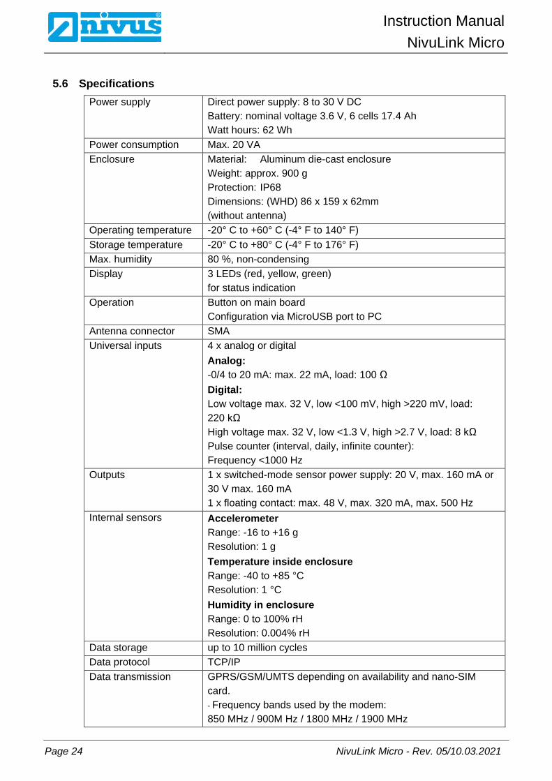
5.6 Specifications Power supply Direct power supply: 8 to 30 V DC
Battery: nominal voltage 3.6 V, 6 cells 17.4 Ah Watt hours: 62 Wh
Power consumption Max. 20 VA Enclosure Material: Aluminum die-cast enclosure
Weight: approx. 900 g Protection: IP68 Dimensions: (WHD) 86 x 159 x 62mm (without antenna)
Operating temperature -20° C to +60° C (-4° F to 140° F) Storage temperature -20° C to +80° C (-4° F to 176° F) Max. humidity 80 %, non-condensing Display 3 LEDs (red, yellow, green)
for status indication Operation Button on main board
Configuration via MicroUSB port to PC Antenna connector SMA Universal inputs 4 x analog or digital
Analog: -0/4 to 20 mA: max. 22 mA, load: 100 Ω Digital: Low voltage max. 32 V, low <100 mV, high >220 mV, load: 220 kΩ High voltage max. 32 V, low <1.3 V, high >2.7 V, load: 8 kΩ Pulse counter (interval, daily, infinite counter): Frequency <1000 Hz
Outputs 1 x switched-mode sensor power supply: 20 V, max. 160 mA or 30 V max. 160 mA 1 x floating contact: max. 48 V, max. 320 mA, max. 500 Hz
Internal sensors Accelerometer Range: -16 to +16 g Resolution: 1 g Temperature inside enclosure Range: -40 to +85 °C Resolution: 1 °C Humidity in enclosure Range: 0 to 100% rH Resolution: 0.004% rH
Data storage up to 10 million cycles Data protocol TCP/IP Data transmission GPRS/GSM/UMTS depending on availability and nano-SIM
card. - Frequency bands used by the modem: 850 MHz / 900M Hz / 1800 MHz / 1900 MHz

6 Installation
NivuLink Micro - Rev. 05/10.03.2021 Page 25
6 Installation
6.1 General Installation Instructions
For electric installation the local regulations in the respective countries (in Germany e. g. VDE 0100) must be referred to. Before powering the device / inserting the battery, fully check the NivuLink Micro installation and sensors, and ensure everything is correct. This device should only be installed by professional and suitabley trained technicians. All legally-binding norms, laws, technical regulations and health and safety guidelines should be followed. The device has protection rating IP68.
6.2 Installing and connecting the NivuLink Micro
CAUTION Risk of injury or damage to device by incorrect installation − Be sure to install the device properly!
− Follow all mandatory and technical guidelines!
CAUTION Risk of damaging device − Do not use the NivuLink Micro with an open cover outdoors!

Instruction Manual
NivuLink Micro
Page 26 NivuLink Micro - Rev. 05/10.03.2021
6.2.1 Selecting the Place of Installation Be aware of the following when deciding where to install the NivuLink:
Important Das NivuLink Micro is not approved for use in closed channels.
Important Note Do not use the NivuLink Micro
− in hospitals and / or near medical devices, like pacemakers or hearing aids
− near highly flammable zones, such as gas stations, storage facilities for flammable materials, chemical plants and explosive sites
− near flammable gases, vapors or dust Avoid as well the following:
• direct sunlight – to prevent the unit from heating up excessively (use a weather-proof cover if necessary, such as the NIVUS Weatherproof Cover, item no. ZMS0180000)
• objects emitting a lot of heat (ambient temperature: -20 to +60°C)
• objects with strong electromagnetic fields (frequency converters, contactors, electric motors requiring highly rated input currents, or similar)
• corrosive chemicals or gases
• mechanical shock
• installation close to footpaths or drives
• vibrations
• radioactive radiation

6 Installation
NivuLink Micro - Rev. 05/10.03.2021 Page 27
6.2.2 Enclosure Dimensions
Fig. 6-1: Enclosure dimensions of the NivuLink Micro in mm

Instruction Manual
NivuLink Micro
Page 28 NivuLink Micro - Rev. 05/10.03.2021
6.2.3 Installing the NivuLink Micro
Important Note Observe to leave enough space at the top for antenna installation. The space re-quirements depend on the antenna used. Do not forget to leave approx. 15 cm of space on the underside of the instrument for cable connections.
Fig. 6-2: Installation holes
Procedure:
• Tightly screw the NivuLink Micro through the holes in the enclosure (1) to a suitable surface, like a wall.

6 Installation
NivuLink Micro - Rev. 05/10.03.2021 Page 29
6.3 Fitting the Antenna 6.3.1 Safety Precautions for fitting the Antenna
WARNING Risk of injury from electric shock − Before connecting the antenna, power off the NivuLink Micro.
Important − Use only antennas that are supplied, or recommended by NIVUS.
− The antenna must be located at least 20 cm away from persons.
− The antenna should not extend beyond the lightning-protected area of buil-dings and must be protected against lightning!
6.3.2 Connecting the Antenna
Important − Gently tighten the antenna.
− Tighten the antenna manually; do not use any tools.
Procedure
1. Disconnect the NivuLink Micro from the power source.
2. Connect the antenna to the antenna connector and carefully tighten by
hand.
3. Reconnect the system to the power supply.

Instruction Manual
NivuLink Micro
Page 30 NivuLink Micro - Rev. 05/10.03.2021
6.4 Open / close the NivuLink Micro Enclosure
1 Lock 2 Screws 3 Cover
Fig. 6-3: NivuLink Micro enclosure Tool required • T20 torx torque screwdriver (TX20)
Open enclosure
Procedure
CAUTION Water damage to device − To best protect NivuLink Micro against moisture, open the cover from
above if it is raining or if you are in a place where water might enter the de-vice.
1. If you are using an external power supply or a charger, disconnect them
from the NivuLink Micro
2. Open the lock (1)
3. Unscrew the screws (2)
4. Open the cover (3)

6 Installation
NivuLink Micro - Rev. 05/10.03.2021 Page 31
Close the enclosure
Procedure
Important Note Particles and pieces of dirt can damage the seal inside the cover.
− Before you close the enclosure, remove any particles and pieces of dirt. The manufacturer will not accept responsibility for damage to the device caused by leaky or damaged seals, or if the cover is incorrectly closed.
1. If necessary, remove any particles and dirt from the seal inside the cov-
er
2. Close the cover (3)
CAUTION Device damage caused by dirt or water If dirt or water enters the terminal compartment, the protection class for the device is no longer valid.
− Close the terminal compartment with the cover and the two screws so that no water or dirt can enter.
3. Make sure the cover is correctly closed and that no particles are caught
between enclosure and cover.
CAUTION Risk of damage to device If the screws are tightened with the incorrect torque, the protection class for the device is no longer valid.
− Tighten the screws with 1.50 Nm torque.
4. Insert screws (2) and tighten with 1.50 Nm torque
5. Tightly press lock (1) against the enclosure until it snaps into place.
The lock is closed

Instruction Manual
NivuLink Micro
Page 32 NivuLink Micro - Rev. 05/10.03.2021
6.5 Insert / change the Nano-SIM Card You can activate the PIN for the nano-SIM card before you insert the card in the NivuLink Micro.
Note Enable the PIN to block unauthorized use of the nano-SIM card in the event of theft!
Activate PIN
Procedure
1. Put the nano-SIM card in a mobile phone
2. Activate PIN
3. Take the nano-SIM card out of the phone
The PIN is activated.
You will need the PIN to configure the modem, see Sect. 7.4.4 "Basic Settings"
Put / replace the nano-SIM card in the NivuLink Micro
Procedure
1. Open the NivuLink Micro enclosure, as described in 6.4 "Open / close
the NivuLink Micro Enclosure"
2. Optional: remove the nano-SIM card from the card holder
3. Slide the nano-SIM card into the card holder. Make sure the contacts on
the card are facing the board.
4. Close the NivuLink Micro enclosure, as described in 6.4 "Open / close
the NivuLink Micro Enclosure"
Fig. 6-4: Slide in the nano-SIM card
6 Installation
NivuLink Micro - Rev. 05/10.03.2021 Page 33
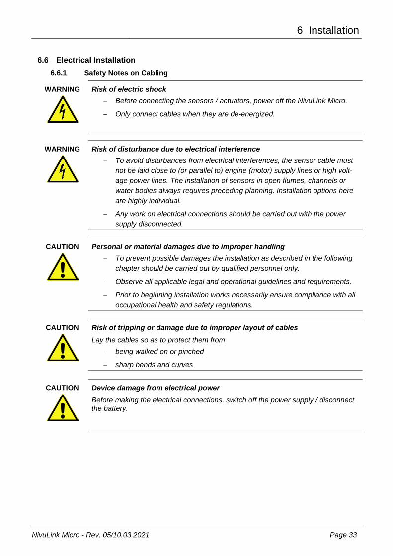
6.6 Electrical Installation 6.6.1 Safety Notes on Cabling
WARNING Risk of electric shock − Before connecting the sensors / actuators, power off the NivuLink Micro.
− Only connect cables when they are de-energized.
WARNING Risk of disturbance due to electrical interference − To avoid disturbances from electrical interferences, the sensor cable must
not be laid close to (or parallel to) engine (motor) supply lines or high volt-age power lines. The installation of sensors in open flumes, channels or water bodies always requires preceding planning. Installation options here are highly individual.
− Any work on electrical connections should be carried out with the power supply disconnected.
CAUTION Personal or material damages due to improper handling − To prevent possible damages the installation as described in the following
chapter should be carried out by qualified personnel only.
− Observe all applicable legal and operational guidelines and requirements.
− Prior to beginning installation works necessarily ensure compliance with all occupational health and safety regulations.
CAUTION Risk of tripping or damage due to improper layout of cables Lay the cables so as to protect them from
− being walked on or pinched
− sharp bends and curves
CAUTION Device damage from electrical power Before making the electrical connections, switch off the power supply / disconnect the battery.

Instruction Manual
NivuLink Micro
Page 34 NivuLink Micro - Rev. 05/10.03.2021
CAUTION Damage due to weather influences The instrument will be damaged as soon as water is leaking into the enclosure.
− In case of rainfall or any other poor weather conditions causing precipitation or potential ingress of water from above the NivuLinkMicro shall be protect-ed appropriately from water leaking into the enclosure
− Make sure to protect the enclosure against ingress of water
− Do not operate NivuLinkMicro out in the field with the cover opened
6.6.2 Notes on Cabling
The NivuLink Micro is shipped with the following cable glands:
• 2 x thread adapter M16 x 1.5
• 1 x plug for thread adapter M16 Cables with the following external cross-sections can be used with the shipped thread adapters:
• M16 x 1.5 5 – 9 mm The following torques apply to the cable gland:
• Spigot 15 Nm
• Cap nut 8 Nm Check cable glands for tightness and retighten if necessary.
Important Note The protection rating IP68 is not guaranteed if cables with diameters greater than these values are used.
Important Note Before initial startup: Close any unused cable glands with a suitable plug. Otherwise, the protection rat-ing for the NivuLink Micro is not guaranteed and the warranty of the legally associ-ated companies and subsidiaries of NIVUS group is void.

6 Installation
NivuLink Micro - Rev. 05/10.03.2021 Page 35
6.6.3 Connecting the Sensors / Actuators
Important Note Note the maximum wire diameter is 1.5 mm² without wire end sleeve, and 1.0 mm² with wire end sleeve.
6.6.3.1 Wiring diagrams
To connect sensors and actuators, please refer to the wiring diagrams below. For the colors of the cables and cores, please refer to the user manuals for the sensors / actuators.
Up to 4 sensors / actuators can be connected to the NivuLink Micro as per these wiring diagrams.
Fig. 6-5: Connecting a 2-wire probe to the NivuLink Micro
Fig. 6-6: Connecting a 3-wire probe to the NivuLink Micro

Instruction Manual
NivuLink Micro
Page 36 NivuLink Micro - Rev. 05/10.03.2021
Fig. 6-7: Connecting an active 4-20 mA output to the NivuLink Micro
Fig. 6-8: Connecting a non-isolated contact to the NivuLink Micro

6 Installation
NivuLink Micro - Rev. 05/10.03.2021 Page 37
6.6.3.2 Typical wiring schemes The wiring diagrams below illustrate typical wiring schemes with sensors and / or actuators. For the colors of the cables and cores, please refer to the user manuals for the sensors / actuators.
Fig. 6-9: Connecting 2 x 2-wire probes to the NivuLink Micro
Fig. 6-10: Connecting 4 x 2-wire probes to the NivuLink Micro

Instruction Manual
NivuLink Micro
Page 38 NivuLink Micro - Rev. 05/10.03.2021
Fig. 6-11: Connecting 4 x active 4-20 mA outputs to the NivuLink Micro
Fig. 6-12: Connecting 4 contacts to the NivuLink Micro
6 Installation
NivuLink Micro - Rev. 05/10.03.2021 Page 39
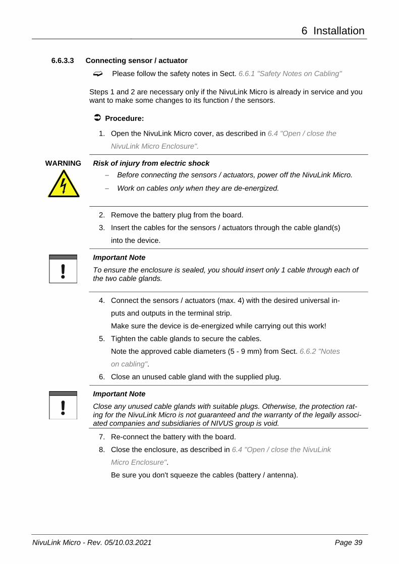
6.6.3.3 Connecting sensor / actuator Please follow the safety notes in Sect. 6.6.1 "Safety Notes on Cabling"
Steps 1 and 2 are necessary only if the NivuLink Micro is already in service and you want to make some changes to its function / the sensors.
Procedure:
1. Open the NivuLink Micro cover, as described in 6.4 "Open / close the
NivuLink Micro Enclosure".
WARNING Risk of injury from electric shock − Before connecting the sensors / actuators, power off the NivuLink Micro.
− Work on cables only when they are de-energized.
2. Remove the battery plug from the board.
3. Insert the cables for the sensors / actuators through the cable gland(s)
into the device.
Important Note To ensure the enclosure is sealed, you should insert only 1 cable through each of the two cable glands.
4. Connect the sensors / actuators (max. 4) with the desired universal in-
puts and outputs in the terminal strip.
Make sure the device is de-energized while carrying out this work!
5. Tighten the cable glands to secure the cables.
Note the approved cable diameters (5 - 9 mm) from Sect. 6.6.2 "Notes
on cabling".
6. Close an unused cable gland with the supplied plug.
Important Note Close any unused cable glands with suitable plugs. Otherwise, the protection rat-ing for the NivuLink Micro is not guaranteed and the warranty of the legally associ-ated companies and subsidiaries of NIVUS group is void.
7. Re-connect the battery with the board.
8. Close the enclosure, as described in 6.4 "Open / close the NivuLink
Micro Enclosure".
Be sure you don't squeeze the cables (battery / antenna).

Instruction Manual
NivuLink Micro
Page 40 NivuLink Micro - Rev. 05/10.03.2021
6.6.4 The NivuLink Micro Power Supply The NivuLink Micro can be powered with a battery and/or a power supply unit. The NivuLink Micro is equipped with a charge controller, but the battery is only charged in continuous operation mode.
Important Note If the modem is switched off, the device can be powered via the USB port. If the modem is switched on, an additional power source, like a battery or an external charger, must be connected.
6.6.4.1 Battery life
The battery life depends on many factors. The tables below give an overview of the expected battery service lifetimes (these values are for information purposes only and are non-binding). Battery life in days NLG with I-Sensor at 17.5 mA Storage cycle (min)
GPRS transmission cycle [hrs.] 1 12 24
1 36 39 39
2 67 76 77
3 93 112 113
5 135 180 183
10 205 330 340
15 248 457 475
30 313 739 788
60 361 1070 1174 Battery life in days NLG with pressure probe at 4 mA Storage cycle (min)
GPRS transmission cycle [hrs.]
1 12 24 1 54 61 61
2 97 118 119
3 131 172 174
5 181 271 277
10 254 475 495
15 293 635 671
30 347 956 1039
60 382 1280 1433

6 Installation
NivuLink Micro - Rev. 05/10.03.2021 Page 41
6.6.4.2 Connect / remove battery
Important Note All rechargeable batteries with integrated, rechargeable energy accumulators are shipped with a charge of max. 30%, in accordance with transportation regulations. The battery should be fully charged before use.
Connect battery
Procedure
1. Open the NivuLink Micro enclosure, as described in 6.4 "Open / close
the NivuLink Micro Enclosure"
2. Insert battery into battery socket
All 3 LEDs light up, the NivuLink Micro is powered on.
3. Close the NivuLink Micro enclosure, as described in 6.4 "Open / close
the NivuLink Micro Enclosure"
Remove battery
Procedure
1. Open the NivuLink Micro enclosure, as described in 6.4 "Open / close
the NivuLink Micro Enclosure"
2. Press the clip on the battery connector against the connector and pull
the connector out of the battery socket
3. Close the NivuLink Micro enclosure, as described in 6.4 "Open / close
the NivuLink Micro Enclosure"

Instruction Manual
NivuLink Micro
Page 42 NivuLink Micro - Rev. 05/10.03.2021
7 Initial Startup
7.1 Initial Startup of System We recommend that the NivuLink Micro is operated first in the office before it is permanently fitted on site. At the same time, you should define a measuring point for later operation on the NIVUS WebPortal (see "Handbook NIVUS WebPortal") as well as a measuring point configuration. Familiarize yourself with the NivuLink Micro functions in a suitable test setting. Simulate the sensors with test I/Os to optimize the NivuLink Micro configuration before placing the device in operation on site. This will reduce the amount of work needed during the actual startup later on site.
7.2 Notes to the User
Before connecting and operating the NivuLink Micro the instructions below shall be followed. This user manual contains all information needed for programming and operating the NivuLink Micro. The manual is intended for qualified personnel. Appropriate knowledge in the areas of instrumentation and electronics are preconditions for putting the NivuLink Micro into operation. Read this instruction manual carefully in order to guarantee proper function of the NivuLink Micro.
For assistance with installing, connecting the device, or programming, you can contact us on our hotline:
• +49 (0) 7262 9191-955
7.3 General Principles The NivuLink Micro shall not be put into operation before the installation has been finished and checked. To exclude faulty programming this instruction manual must be read before the initial start-up. Using the user manual, familiarize yourself with the operation of the NivuLink Micro before you configure the device. First connect the sensors / actuators (according to Sect. 6.6.3.3 "Connecting the Sensors / Actuators”); then, configure the NivuLink Micro with the NivuLink Micro configuration tool. You will need to specify the following:
• Measurement and Transmission Interval
• Limit Values if required The user interface of the NivuLink Micro configuration tool was designed in a way that even unfamiliar users are able to easily set up basic settings in dialog mode which ensure reliable device operation.
For extensive programming, difficult hydraulic conditions, in case of absence of expert staff or if a setup and error protocol is required, the programming should be carried out by the NIVUS GmbH or an expert company which is authorised by the NIVUS GmbH.

7 Initial Startup
NivuLink Micro - Rev. 05/10.03.2021 Page 43
7.4 Using the NivuLink Micro Configuration Tool (valid as of software version 1.3.3.0)
To configure the NivuLink Micro you will need the NivuLink Micro configuration tool software. You can download the NivuLinkMicro configuration tool in the NIVUS Download Centre. Follow the installation instructions to install the NivuLink Micro configuration tool on your system.
The configuration covers:
• Analog or Digital Inputs
• The wireless data transmission to a server (NIVUS WebPortal)
• Measurement and Transmission Interval
• Processing of Limit Values
Basic Notes on Configuration:
• The NivuLink Micro firmware is updated automatically.
• Valid decimal separators: dot and comma
Important Note If the modem is switched off, the device can be powered via the USB port. If the modem is switched on, an additional power source, like a battery or an external charger, must be connected.

Instruction Manual NivuLink Micro
Page 44 NivuLink Micro - Rev. 05/10.03.2021
7.4.1 Splash Screen for the NivuLink Micro Configuration Tool Executing the NLM_ConfigTool.exe file (double click) will open the start screen of the NivuLink Micro configuration tool.
1 Indicates the link status, here: disconnected There is a detailed description in the next figure (Fig. 7-2).
2 Opens a drop-down menu where the configuration level can be selected: Normal: standard view with the standard options for the use of the NI-VUS WebPortal. Extended: extended view (password protected) with further options for using NIVUS DataKiosk or NICOS, can only be opened with a password received from NIVUS. Service: Service screen. This screen can only be opened by NIVUS Service technicians.
3 Opens the drop-down menu to select the language for the configuration tool: German / English / French.
4 Button Send configuration to device The button is enabled only if a link to a NivuLink Micro exists. The button transmits the configuration to the NivuLink Micro and restarts the NivuLink Micro.
Important Note If a configuration is transmitted to the NivuLink Micro, a battery or an external charger must be connected.

7 Initial Startup
NivuLink Micro - Rev. 05/10.03.2021 Page 45
5 Button Save configuration as file The button opens the File Manager to select the storage location for the configuration and to store it in the format *.nlu.
6 Button Load configuration from file The button opens the File Manager to select a saved configuration (file format *.nlu) and to load it.
7 Button Load configuration from device This button is enabled only if there is a link to a NivuLink Micro. The button loads the configuration from the NivuLink Micro in order to edit it.
8 Button Reboot device This button is enabled only if there is a link to a NivuLink Micro. The button restarts the NivuLink Micro without a configuration having been transmitted to it.
9 Selecting tabs, here: Basic settings, Channels and Thresholds. The tabs Modem settings and Software-update appear in the extended screen.
Fig. 7-1. NivuLink Micro configuration tool: Splash screen
For a description of the tabs and options, please refer to Sects “7.4.4 “Basic Settings”, 7.4.5 “Modem Settings“, 7.4.6 “Measurement Chan-nels”, 7.4.7 “Thresholds”, 7.4.8 “Serial Port“ and 7.4.9 “Software Up-date“
Connection status
1 Button Connect to device The button connects to a NivuLink Micro if the following conditions are met: - There is no device link (link status = red)- A NivuLink Micro is in configuration mode and connected via USB cable tothe computer.
2 Shows the serial number of the NivuLink Micro that is or will be connected to (not editable).
3 Shows the link status: Red: no connection Yellow: connection is being established Green: connected
Fig. 7-2: NivuLink Micro configuration tool: Splash screen > Link status

Instruction Manual NivuLink Micro
Page 46 NivuLink Micro - Rev. 05/10.03.2021
7.4.2 Connect Configuration Tool with the NivuLink Micro Required accessories • Micro USB cable
Prerequisite • The NivuLink Micro is connected to a power supply.
• The NivuLink Micro configuration tool is open.
Procedure:
1. Put the NivuLink Micro in the configuration mode:
Press the configuration-mode button (Fig. 5-2) until the green LED next
to the button is lit permanently and the yellow LED goes off.
Note: the configuration mode will be terminated automatically after 10 min. (asof hardware version 2C).
2. Connect the NivuLink Micro with the computer:Plug the USB cable into the USB ports in the NivuLink Micro and in the
computer
3. Click the Connect to device button on the start screen of the NivuLink
Micro configuration tool
The serial number is shown in the text field next to the button.
While the link is being established: the link status is shown in yellow.
When the link has been established: the link status is shown in green.
Next step • Configure the NivuLink Micro
• or load configuration
• or change configuration

7 Initial Startup
NivuLink Micro - Rev. 05/10.03.2021 Page 47
7.4.3 Configuration Options Below you can find the basic configuration options. A detailed description of the options can be found in chapters 7.4.4
“Basic Settings” 7.4.5 "Modem Settings“, 7.4.6 "Measurement Chan-nels“, 7.4.7 "Thresholds“ ,7.4.8 “Serial Port“ and 7.4.9 “Software Up-date”
Important Note If a configuration is transmitted to the NivuLink Micro, a battery or an external charger must be connected.
7.4.3.1 Configure a NivuLink Micro
Procedure
1. Connect the configuration tool and the NivuLink Micro (see Sect. 7.4.2)
2. Configure the NivuLink Micro
3. Send configuration to device (see Fig. 7-1, Pos. 4)
The configuration is transmitted to the NivuLink Micro.
The NivuLink Micro restarts (operation mode).
7.4.3.2 Configure several NivuLink Micros at the same Time
If you require the same configurations for several NivuLink Micros, you only need to carry out the configuration once and can transmit it to all other units.
Procedure
1. Connect the configuration tool and a NivuLink Micro (see Chapter 7.4.2)
2. Configure the NivuLink Micro
3. Send configuration to device ( see Fig. 7-1, Pos 4)
The configuration is transmitted to the NivuLink Micro.
The NivuLink Micro restarts (operation mode).
4. Connect the configuration tool and another NivuLink Micro (see Chap-
ter 7.4.2)
5. Send configuration to device
The configuration is transmitted to the NivuLink Micro.
The NivuLink Micro restarts (operation mode).
6. Repeat steps 4 and 5 for all further devices

Instruction Manual NivuLink Micro
Page 48 NivuLink Micro - Rev. 05/10.03.2021
7.4.3.3 Save the Configuration You can save the configuration of a NivuLink Micro in a file
• for backup purposes
• for later transmission to another device
Procedure
1. Connect the configuration tool and the configured NivuLink Micro (see
Chapter 7.4.2)
2. Load configuration from device (see Fig. 7-1, Pos. 7)
3. Save configuration as file (see Fig. 7-1, Pos. 5)
The file manager opens.
4. Navigate to the desired location and save the file
7.4.3.4 Transmit saved Configuration to a NivuLink Micro You can transmit the saved configuration of a NivuLink Micro to another device.
Procedure
1. Connect the configuration tool and a NivuLink Micro to which the confi-
guration is to be transmitted.
2. Load configuration from file (see Fig. 7-1, Pos. 6)
The file manager opens.
3. Navigate to the desired file
4. Send configuration to device (see Fig. 7-1, Pos. 4)
The configuration is transmitted to the NivuLink Micro and saved.
The NivuLink Micro restarts (operation mode).

7 Initial Startup
NivuLink Micro - Rev. 05/10.03.2021 Page 49
7.4.3.5 Change Configuration
Procedure
1. Connect the configuration tool and the configured NivuLink Micro (see
Chapter 7.4.2)
2. Load configuration from device (see Fig. 7-1, Pos. 7)
3. Change Configuration
4. Send configuration to device (see Fig. 7-1, Pos. 4)
The Transmit Configuration dialog window opens.
5. Select Option:
Yes, to delete the old measurement data on the device at the same time
No, to maintain the old measurement data on the device
The configuration is sent to the NivuLink Micro in any case and the follo-
wing window opens:
6. Click OK
The configuration was transmitted to the NivuLink Micro.
The NivuLink Micro restarts (operation mode).

Instruction Manual NivuLink Micro
Page 50 NivuLink Micro - Rev. 05/10.03.2021
7.4.4 Basic Settings The following options are available in the Normal screen of the "Basic settings" tab:
• Serial number
• Operation mode
• Test mode
• Measuring
• Sensor
• Location
• Modem settings
In the extended screen, the following additional options are available:
• Communication hub
• Time synchronisation
The extended view mode shows the Modem settings option as a separate tab.
Serieal number The serial number of the NivuLink Micro is automatically read from the circuit board and cannot be changed. The NivuLink Micro reports to the communication hub using the serial number.
Operation mode The drop-down menu for the operating mode is available here with the options
• Interval: The NivuLink Micro goes into sleep mode after every scan to save en-ergy. The data are transmitted after the configured transmission interval.
• Permanent: The NivuLink Micro remains switched on and transmits each mea-surement at the configured transmission interval, counter and charge controllerfunction. The continuous operation is intended for counter applications andmains-powered devices.
Additionally, you can activate/deactivate the test mode.
• Test mode: once test mode is enabled (= checked) NivuLink Micro will transmitfive measurements directly on the first start-up. This allows you to verify wheth-er a connection to the server can be set up and whether all settings are correct.

7 Initial Startup
NivuLink Micro - Rev. 05/10.03.2021 Page 51
Measuring
1 Entry field for the scan interval in minutes (= measurement interval) 2 Drop-down menu to select transmission periods:
Interval: 3 = specify the transmission interval in minutes (= interval of data transmission to communication hub) Fixed time: 3 = specify a fixed point in time for daily transmission of data to the communication hub; format HH:MM (e. g. 14:00)
3 Input field for transmission interval or time (see 2)
Fig. 7-3: NivuLink Micro configuration tool: Basic settings > Scanning
Sensor
1 Dropdown menu to select the sensor type. Custom: you must specify the sensor configuration (2 and 3) manually. iSensor / Hydrostatic Pressure Probe / VEGAPULS C 21: the sensor con-figuration (2 and 3) is loaded automatically.
2 Entry field for the warm-up time in seconds Warm-up time: the time before measurements are taken, when voltage is applied at the Vsens output.
3 Opens the drop-down menu to select the sensor voltage. This is the voltage the sensor needs and which is output via Vsens.
Fig. 7-4: NivuLink Micro configuration tool: Basic settings > Sensor
Location Configure the GPS coordinates of the position of your NivuLink Micro here. These coordinates are used to indicate the position in the mesuring point configuration of the NIVUS WebPortal later. The position of the NIVUS headquarters is shown if no values are specified here.

Instruction Manual
NivuLink Micro
Page 52 NivuLink Micro - Rev. 05/10.03.2021
Modem settings The modem settings for operation with the nano-SIM card are made here.
1 The drop-down menu opens to allow you to select one of the defaults Template Use Included in the delivery
of Custom Any SIM Card -- NIVUS Card (for NLG00MICROEE)
Wireless-Logic SIM Card NLG MICRO EE NLG MICRO EE 0S0
NIVUS Card (for NLG00MICROEG)
NIVUS-Vodafone SIM Card
NLG00 Micro EG NLG00 Micro EG 0S0
Telekom Standard Telekom SIM Card
--
Vodafone Standard Vodafone SIM Card
--
2 Entry field for the APN (= access point to a mobile network) of the mobile network for the data transmission
3 Entry field for the user name 4 Entry field for the password 5 Entry field for a PIN
If the nano-SIM card is configured so that the system requests the PIN to be entered when the modem is switched on, then the PIN must be entered here.
Fig. 7-5: NivuLink Micro configuration tool: Basic settings > Modem settings
Note Enable the PIN to block unauthorized use of the nano SIM card in the event of theft!

7 Initial Startup
NivuLink Micro - Rev. 05/10.03.2021 Page 53
Configure the modem settings depending on the SIM card used as follows:
Template APN Username Password PIN Custom depending on the
mobile phone provider
according to the specifications of the mobile phone provider
according to the specifications of the mobile phone provider
according to the specifications of the mobile phone provider
NIVUS Card (for NLG00MICROEE)
wlapn.com(filled in by the system)
nivus nivus --
NIVUS Card (for NLG00MICROEG
nivus (filled in by the system)
-- -- --
Telekom internet.telekom(filled in by the system)
any (optional)
any (optional)
4-digit number (optional)
Vodafone web.vodafone.de (filled in by the system)
any (optional)
any (optional)
4-digit number
Communication hub This option is available only in the extended screen. The broker is the counterpart (server) to which the data are transmited from the NivuLink Micro.
1 Drop-down menu to select the server to which data from NivuLink Micro are to be sent. Options: NIVUS server and Own server. Choosing Own server enables input fields 2 – 5.
2 Entry field for the target IP address or the target domain 3 Entry field for the target port 4 Entry field for the password 5 Entry field for the user name 6 Activates / deactivates encrypted data transmission (TLS)
Fig. 7-6: NivuLink Micro configuration tool: Basic settings > Communication hub

Instruction Manual
NivuLink Micro
Page 54 NivuLink Micro - Rev. 05/10.03.2021
Time synchronisation This option is available only in the extended screen.
1 Activates / deactivates time synchronisation between device and time server (3) = default setting
2 Activates / deactivates time synchronisation between communication hub and time server (3) = special setting for customer server, private network and respective job
3 Only active if (1) is activated: Entry field for the time server to be used for the time synchronization of the NivuLink Micro
4 Only active if (1) is activated: Entry field for the time server port 5 Entry field for the synchronization interval in hours
Fig. 7-7: NivuLink Micro configuration tool: Basic settings > Time synchro-nization
Note An active modem link is needed for the time synchronization. For a longer battery service life, the synchronization interval should not be smaller than the transmis-sion interval (see "Measurement option").
7.4.5 Modem Settings
The Modem settings tab is available only in extended view mode. For a description of the modem settings, please refer to Sect “7.4.4 Ba-
sic Settings“ > Modem settings.

7 Initial Startup
NivuLink Micro - Rev. 05/10.03.2021 Page 55
7.4.6 Measurement Channels The following options are available in the Channels tab: • External channels: Option for configuring the external sensors. • Internal channels: This option is enabled only in the Service screen.
External channels Configure the external sensors here. The NivuLink Micro has 4 universal inputs. Each universal input is configured in one double line.
1 Enable / disable the input 2 Entry field for the name of the input 3 Drop-down menu where the input mode is selected.
The table below contains a detailed description of the modes. 4 Tick set = the signal is inverted (logical 1 becomes 0) 5 Editable only in the extended view: Drop-down menu to select the calculation
method: Factorization, Formula or Interpolation The selection is relevant only as soon as Calculation (8) is enabled (= checked).
6 Editable only in the extended view: When (4) = Factorization: input field for the factor When (4) = Formula: input field for the formula
7 Editable only in the extended view: Opens the value table used to configure the interpolation values
8 Editable only in the extended view: Enables / disables the further calculation of measurement values
9 Editable only in the extended view: Enables / disables the switching contact which can be set on the server (switching contact can only be set in Perma-nent operation mode.)
Fig. 7-8: NivuLink Micro configuration tool: Channels > External channels

Instruction Manual
NivuLink Micro
Page 56 NivuLink Micro - Rev. 05/10.03.2021
Modes More fields are blended in depending on the mode. Mode Description Field Notes Analog input Transmits the
unscaled digit values from the sensor
- -
0-20 mA 4-20 mA
Setting that corresponds with the sensor range. Editab-le only in the Extended View.
0 % Entry fields for scaling the measurements w.r.t. the output unit.
100 %
Unit Entry field for the output unit. (The measurement is converted to this unit.)
Decimal places
Entry field for the decimal places for the output unit.
Digital High Voltage Digital Low Voltage
Transmits digi-tal signals in high or low-voltage range
invert Checkbox ticked: The sig-nal is transmitted inverted.
Counter High Voltage Counter Low Voltage (works only in conti-nuous operation)
Counts and transmits the positive edge changes in the high- or low-voltage range of a counter.
Impulse Entry field for the value the pulse should have.
Unit Entry field for the pulse output unit.
Decimal places
Entry field for the decimal places for the output value.
7.4.7 Thresholds
Define an event threshold as well as five high and low limit values for the first input here. This enables you to adjust measurement and transmission intervals and to issue error messages in connection with the NIVUS WebPortal or with the NICOS system.
Observe the following notes:
• It is not necessary to configure all thresholds. If only one threshold is required, only one threshold needs to be configured.
• The event threshold and the high thresholds are reached once they have been exceeded. The low thresholds are reached once the value drops below the ad-justed limit.
• Configure the high thresholds as ascending. Threshold 1 contains the smallest value, while threshold 5 contains the largest. Configure the low thresholds ac-cordingly as descending.
• When going beyond the thresholds the absolute and relative deviation will be taken into account. The higher one of the both values is used. Going beyond a threshold once reached will occur only as soon as the measurement value is lower than the threshold minus the deviation (high thresholds) or higher than the threshold plus the deviation (low thresholds).

7 Initial Startup
NivuLink Micro - Rev. 05/10.03.2021 Page 57
• If measurement or transmission intervals have been modified, the lowest of each will be used. If a fixed point in time has been specified as transmission time in the basic settings, the setting made here will overwrite this transmission time and will replace it by the interval transmission configured here.
• The values you set in the Threshold column input fields relate to the scaling selected in the Measurement Channels tab.
1 Activates / deactivates threshold processing scaling (enables threshold input
scaled, data transmission is in digits). The function is only relevant if the measuring value processing is done in di-gits (Measurement Channels > external Channels > Mode > Analog in-put). If you activate the function, then you can configure the limit value in clear va-lues.
2 Setting that must correspond to the measurement range of the sensor 3 Input field for the start value 4 Input field for the end value 5 Threshold Configuration
The description of the threshold configuration can be found in the following table.
Fig. 7-9: NivuLink Micro configuration tool: Thresholds
Threshold Configuration: Column Remarks Threshold Input fields for event threshold and for the high or low
limit value thresholds Absolute hysteresis Input fields for the deviation related to scaled limit
values Relative hysteresis [%] Input fields for deviation related to the latest saved
measuring value Read interval [min] Input fields related to event threshold, high or low limit
values Transmit interval [min]

Instruction Manual
NivuLink Micro
Page 58 NivuLink Micro - Rev. 05/10.03.2021
7.4.8 Serial Port The Serial Port tab is available only in the extended view. KDO Sensor
You will find all information on this in the Technical Information Connec-tion Sensor KDO to NivuLink Micro. If required, request this document from NIVUS GmbH.
7 Initial Startup
NivuLink Micro - Rev. 05/10.03.2021 Page 59
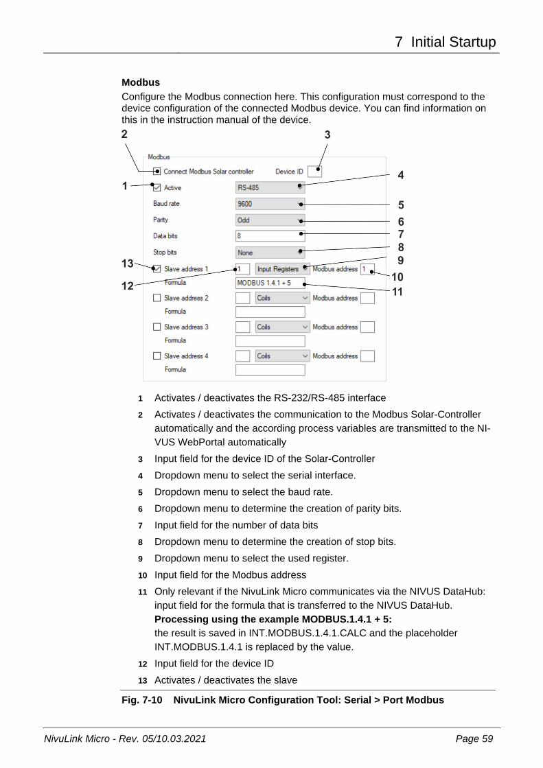
Modbus Configure the Modbus connection here. This configuration must correspond to the device configuration of the connected Modbus device. You can find information on this in the instruction manual of the device.
1 Activates / deactivates the RS-232/RS-485 interface 2 Activates / deactivates the communication to the Modbus Solar-Controller
automatically and the according process variables are transmitted to the NI-VUS WebPortal automatically
3 Input field for the device ID of the Solar-Controller 4 Dropdown menu to select the serial interface. 5 Dropdown menu to select the baud rate. 6 Dropdown menu to determine the creation of parity bits. 7 Input field for the number of data bits 8 Dropdown menu to determine the creation of stop bits. 9 Dropdown menu to select the used register. 10 Input field for the Modbus address 11 Only relevant if the NivuLink Micro communicates via the NIVUS DataHub:
input field for the formula that is transferred to the NIVUS DataHub. Processing using the example MODBUS.1.4.1 + 5: the result is saved in INT.MODBUS.1.4.1.CALC and the placeholder INT.MODBUS.1.4.1 is replaced by the value.
12 Input field for the device ID 13 Activates / deactivates the slave
Fig. 7-10 NivuLink Micro Configuration Tool: Serial > Port Modbus

Instruction Manual
NivuLink Micro
Page 60 NivuLink Micro - Rev. 05/10.03.2021
When the NivuLink Micro communicates with NICOS, configure the Item address in NICOS Studio as follows: INT.MODBUS.1.2.3 Variable Value See Fig. 7-10 Variable 1 Slave Address > Device ID Pos. 12 Variable 2 Coils
Input Discretes Multiple Registers Input Regsiters
Variable Value 1 Variable Value 2 Variable Value 3 Variable Value 4
Pos. 9
Variable 3 Modbus Address Pos. 10 In the example configuration in Fig. 7-10, this results in the following Item address: INT.MODBUS.1.4.1
7.4.9 Software Update The software update tab is available only in the extended view. You can update the NivuLink Micro software here.
1 Opens the File Manager to select the new software 2 Shows the selected software 3 Loads the selected software to the NivuLink Micro and restarts the device
Prerequisite: There must be a connection to a NivuLink Micro
Fig. 7-11 NivuLink Micro Configuration Tool: Software Update

8 Maintenance and Cleaning
NivuLink Micro - Rev. 05/10.03.2021 Page 61
8 Maintenance and Cleaning
DANGER Health hazard due to germs Wastewater may be contaminated with dangerous germs.
− Should the measurement system be used in the wastewater area make sure to take respective precautions when getting in contact with system, transmitter, cables and sensors.
− Always wear protective clothing.
WARNING Danger by electric voltage Prior to beginning maintenance, cleaning and / or repair works (to be executed by qualified expert personnel only):
− disconnect the device from mains power supply or disconnect the re-chargeable battery
− Disable the higher system from restarting.
CAUTION Damage due to improper maintenance, repairs or cleaning Improper maintenance, repairs or cleaning can damage the NivuLink Micro / the sensors and cause the device to malfunction.
− Maintenance, cleaning or repairs should be carried out by qualified techni-cians only.
8.1 Installation of Spare Parts and Parts Subject to Wear and Tear We herewith particularly emphasise that replacement parts or accessories not supplied by NIVUS moreover are not certified and approved by NIVUS too. Installation and/or the use of such products hence may negatively influence predetermined constructional characteristics of the measurement system or even lead to instrument failures. NIVUS cannot be held responsible for any damage resulting due to the use of non-original parts and non-original accessories. You can find original manufacturer spare parts or accessories in chapter
9 “Spare Parts and Accessories” and/or in the valid price list
8.2 Maintenance 8.2.1 Maintenance Interval
The NivuLink Micro is conceived to be virtually free of calibration, maintenance and wear (requirements of the Industrial Safety Regulations are unaffected). NIVUS recommends having the entire measurement system inspected by the NIVUS customer service once per year. NIVUS recommends to have the measurement system completely be inspected by a legally associated company or subsidiary of NIVUS group after latest ten years. Generally the verification of instruments and sensors is a basic measure in order to improve operational reliability and to increase the lifetime.

Instruction Manual
NivuLink Micro
Page 62 NivuLink Micro - Rev. 05/10.03.2021
8.2.2 Customer Service Information For the recommended annual inspection of the entire measurement system and/or the exten-sive inspection after latest ten years contact our customer service:
NIVUS GmbH – Customer Service Phone +49 (0) 7262 9191 - 922 [email protected]
8.2.3 Standard Maintanance Regularly check the following
• that the NivuLink Micro is not mechanically damaged
• that all joints and connections are properly sealed and not corroded
• that there is no physical damage to cables
8.2.4 Charging the Battery
CAUTION Risk of injury and risk of material damage − Do not charge the battery on a combustible surface.
− Be present while the battery is charging.
CAUTION Material damage caused by using an incorrect charger The battery can be irreversibly damaged if the wrong type of charger is used: the cells can be drained or an explosion can occur, for example.
− Use charger NLG0 LAD AP 5414 only.
Important Note Batteries wear out and discharge over time. They also loose charge at high / low temperatures as well as when they are used a lot.
Current transportation guidelines dictate that all batteries with an integral rechargeable energy accumulator are shipped with a charge of max. 30%. If you use an external charging voltage (V IN) during operation and have set the operating mode to continuous operation, the battery is constantly recharged by the charge controller integrated in the NivuLink Micro.
If no external charger (V IN) is available during production, the battery must be fully charged before initial startup.

9 Spare Parts and Accessories
NivuLink Micro - Rev. 05/10.03.2021 Page 63
8.3 Cleaning 8.3.1 NivuLink Micro
CAUTION Equipment damage due to improper cleaning Improper cleaning may damage the logger / the sensors which may lead to meas-urement failure.
− Do not clean the instrument with scouring, scratching or abrasive tools or media.
− Do not use organic solvents to clean logger, sensors and sensor cables.
− Do not clean the logger / the sensors with high-pressure cleaners.
− Do not use sharp cleansing agents or solvents.
Clean the NivuLink Micro enclosure if required using a dry, lint-free cloth. For heavy dirt wipe the enclosure with a damp cloth.
8.3.2 Sensors The hints on how to maintain and to clean the sensors shall be necessarily observed. These hints can be found in the according technical description or the according instruction manual. The technical description or instruction manual is part of the standard sensor delivery.
9 Spare Parts and Accessories
9.1 Spare Parts Enclosure seal Cable gland M16 x 1.5 Plug for threaded adapter M16 x 1.5

Instruction Manual
NivuLink Micro
Page 64 NivuLink Micro - Rev. 05/10.03.2021
9.2 Accessories Analysis (software) Specified by customer
a) in the customer's NICOS process control system b) On a central server in the NIVUS WebPortal (included in the purchase proce for the life of the device) c) NIVUS DataKiosk
Power adapter NLG0 NETZ G01
Input voltage: 90...264 V AC Output voltage: 24 V Output current: 1.04 A Output power: 25 W Primary plug: EU
DIN rail power adapter NLM0 S8 NETZ 24V
Input voltage: 100…240 V AC Output voltage: 24 V Output current: 2,5 A
Rechargeable battery pack NLG0 AP 5414
Lithium-Ion, chargeable at > 0 °C Nominal voltage: 3.6 V Charging voltage: 4.2 V Nominal capacity:17.4 Ah Nominal energy: 62.6 Wh
Charger for battery pack NLG0 AP xxx NLG0 LAD AP 5414
Input: 100 - 240 V AC (50 - 60 Hz) Output: 12 W; 4.1 V; 2.4 A
Tool set NLG00 TOOLSET
Delivery: - 1 x USB micro data cable - 1 x slot screwdriver - 1 x Torx screwdriver
Multi-band rod antenna NLG0 ANT STAB
GSM/3G/868, FME female, rod antenna length 57 mm
Antenna adapter NLM0 S8 ANT ADAPT
FME(m) to SMA(m)
Antenna extension NLM0 ANT VER 05
Antenna extension 5 m (in connection with antenna adapter NLM0 S8 ANT ADAPT only)
GSM round antenna NLM0 EMAT R01
incl. holder for installation in dust pan or for wall mounting (in connection with antenna adapter NLM0 S8 ANT ADAPT only)
Magnetic base antenna ZUB0 M ANT
9 cm with 2.5 m Kabel (in connection with antenna adapter NLM0 S8 ANT ADAPT only)
GSM station antenna ZUB0 GSM 01
GSM station antenna with rod holder for outdoor installation (in connection with antenna adapter NLM0 S8 ANT ADAPT only)
More accessories can be found in our current price list.

10 Dismantling / Disposal
NivuLink Micro - Rev. 05/10.03.2021 Page 65
10 Dismantling / Disposal
10.1 Disassembling / Disposing of the NivuLink Micro Incorrect disposal may be a potential threat to the environment. Always dispose equipment components and packaging material according to applicable local regulations on environmental standards for electronic products.
Procedure
1. Disconnect the NivuLink Micro from the grid
2. Remove battery, if necessary, and dispose of it separately
3. Disconnect the cables with suitable tools
4. Remove the NivuLink Micro from its fixture
EU WEEE Directive logo This symbol indicates that the Directive 2012/19/EU on waste electrical and elec-tronic equipment requirements shall be observed on the disposal of the equipment. NIVUS GmbH supports and promotes the recycling and environmentally friendly, separate collection/disposal of waste electrical and electronic equipment in order to protect the environment and human health. Observe the local disposal regulations and laws.
NIVUS GmbH is registered with the EAR, therefore public collection and return points in Germany can be used for disposal.
The device is equipped with a rechargeable battery that must be disposed of separately.
10.2 Dispose of Batteries When discharged, the battery should not be left in the NivuLink Micro. Be sure to dispose of batteries in an enviromentaly friendy manner. Return used batteries to the manufacturer or drop them off at a recycling center.

Instruction Manual
NivuLink Micro
Page 66 NivuLink Micro - Rev. 05/10.03.2021
11 Use Cases
11.1 Level Monitoring in a closed Vessel
Fig. 11-1: Level monitoring in a closed vessel, e.g., with a sensor
11.2 Level Monitoring at a Stormwater Overflow Tank with max. Basin Level and Basin Overflow
Fig. 11-2: Level monitoring at a stormwater overflow tank with max. basin le-vel and basin overflow

EU Declaration of Conformity
NivuLink Micro - Rev. 05/10.03.2021 Page 67
EU Declaration of Conformity