INSTRUCTION MANUAL GAS/INDUCTION COOKTOPS
28
INSTRUCTION MANUAL GAS/INDUCTION COOKTOPS MODELS ILBV94+1 and ILWV94+1
Transcript of INSTRUCTION MANUAL GAS/INDUCTION COOKTOPS

INSTRUCTION MANUAL GAS/INDUCTION COOKTOPSMODELS ILBV94+1 and ILWV94+1
sbarone
Typewritten Text
sbarone
Typewritten Text
sbarone
Typewritten Text
sbarone
Typewritten Text
sbarone
Typewritten Text
sbarone
Typewritten Text
sbarone
Typewritten Text
sbarone
Typewritten Text
sbarone
Typewritten Text
sbarone
Typewritten Text
sbarone
Typewritten Text
OPEN 24/7ILVE ACCESSORIES ONLINE SHOP
-VY�H�^PKL�YHUNL�VM�JVɈLL�THJOPULZ��WVKZ��HUK�V[OLY�03=,�HJJLZZVYPLZ�H[�[OL�JSPJR�VM�H�I\[[VU�ZOVW�PS]L�JVT�H\

3
GB
Dear customer,We thank you and congratulate you on your choice.This new carefully designed product, manufactured with the highest quality materials, has been carefully tested to satisfy all your cooking demands.We would therefore request you to read and follow these easy instructions which will allow you to obtain excellent results right from the start.May we wish you all the very best with your modern appliance!
THE MANUFACTURER
IndexUser instructionsInstallationUseMaintenance Gas/ElectricalInductionOperating principleUseFunctionsMaintenance
Installation instructionsInstallationPositioningGas connectionAdaptation to varius types of gasElectrical connection
THIS APPLIANCE IS CONCEIVED FOR DOMESTIC USE ONLY. THE MANUFACTURER S NI TON LLAHANY WAY BE HELD RESPONSIBLE FOR WHATEVER INJURIES OR DAMAGES ARE CAUSED BY INCORRECT INSTALLATION OR BY UNSUITABLE, WRONG OR ABSURD USE. THIS APPLIANCE IS NOT INTENDED FOR USE BY PERSONS (INCLUDING CHILDREN) WITH REDUCED PHYSICAL,
SENSORY OR MENTAL CAPABILITIES, OR LACK OF EXPERIENCE AND KNOWLEDGE, UNLESS THEY HAVE BEEN GIVEN SUPERVISION OR INSTRUCTION CONCERNING USE OF THE APPLIANCE BY A PERSON RESPONSIBLE FOR THEIR SAFETY.CHILDREN SHOULD BE SUPERVISED TO ENSURE THAT THEY DO NOT PLAY WITH THE APPLIANCE.
For service and spare parts, pleasecall the relevant number listed on the back page of this manual.

4
GB
InstallationAll the operations concerned with the installation (electrical and gas connections, adaptation to type of gas, necessary adjustments, etc.) must be carried out by qualified technicians, in terms with the standards in force. For specific instructions, kindly read the part reserved for the installation technician.DO NOT FOCUS INENSEL ON THE LEDS AND DISPLAYS.
UseUse Gas burnersThe ignition of the gas burner is carried out by putting a small flame to the upper part holes of the burner, pressing and rotating the corresponding knob in an anti-clockwise manner, until the maximum position has coincided with the marker. When the gas burner has been turned on, adjust the flame according to need. The minimum position is found at the end of the anti-clockwise rotation direction. For models with automatic/ simultaneous (with one hand) ignition, it is sufficient to proceed as described above using the corresponding knob. The electric spark between the ignition plug and the burner provides the ignition of the burner itself. After ignition, immediately release the push-button and adjust the flame according to need. For models with a thermoelectric safety system, the burner is ignited as in the various cases described above, keeping the knob fully pressed on the maximum position for approximately 3/5 seconds. After releasing the knob, make sure the burner is actually lit. N.B.- We recommend the use of pots and pans with a diameter matching that of the burner,
thus preventing the flame from escaping from the bottom part and surrounding the pot;- do not leave any empty pots or pans on the fire;- do not use any tools for grill-cooking on Crystal hobs.
When cooking is finished, it is also a good norm to close the main gas pipe tap and/or cylinder. Dual Wok BurnerThe hotplate has a Dual Wok burner. The centre flame (F1) can be lit by pressing the knob and turning it clockwise or the entire burner (F2) can be lit as shown in the figure below.
F1F2
F1F2
F1F2
User instructions
DO NOT USE OR STORE FLAMMABLE MATERIALS NEAR THIS APPLIANCE.DO NOT SPRAY AEROSOLS IN THE VICINITY OF THIS APPLIANCE WHILE IT IS IN OPERATION.DO NOT MODIFY THIS APPLIANCE.
WHERE THIS APPLIANCE IS INSTALLED IN MARINE CRAFT OR IN CARAVANS, IT SHALL NOT BE USED AS A SPACE HEATER.
The appliance is not suitable for use with aftermarket lids or covers.

5
ImportantOn floors with thermoelectric protection do not keep the ignite button pushed for more than 15 seconds. If the burner has not ignited after 15 seconds, open the door of the room and wait at least one minute before making a further attempt.
wok Ø 20-32
*with reduction grid
GAS
Fig. 1
Maintenance Gas/ElectricalPrior to any operation, disconnect the appliance from the electrical system. For long-life to the equipment, a general cleaning operation must take place periodically, bearing in mind the following:• the glass, steel and/or enamelled parts must be cleaned with suitable non-abrasive or
corrosive products (found on the market). Avoid chlorine-base products (bleach, etc.);• avoid leaving acid or alkaline substances on the working area (vinegar, salt, lemonjuice,
etc.);• the wall baffle and the small covers (mobile parts of the burner) must be washed frequently
with boiling water and detergent, taking care to remove every possible encrustation. Dry carefully and check that none of the burner holes is fully or partially clogged;
• the electrical parts are cleaned with a damp cloth and are lightly greased with lubricating oil when still warm;
• the stainless steel grids of the working area, after having been heated, take on a bluish tint which does not deteriorate the quality. To bring colour back to its original state, use as lightly abrasive product.
N.B.- Cleaning of the taps must be carried out by qualified personnel, who must be consulted in case of any functioning anomaly. Check periodically the state of conservation of the flexible gas feed pipe. In case of leakage, call immediately the qualified technicians for its replacement.
DO NOT USE STEAM CLEANERS
Warning: If the surface is cracked, switch off the appliance to avoid the possibility ofelectric shock.
Metallic objects such as knives, forks, spoons and lids should not be placed on the hob surface since they get hot.

6
InductionHeating by induction is the most efficient form of cooking available.The heat is generated by an electromagnetic field, directly on the bottom of the pan or pot used. The surface which is free from contact remains virtually cold. When the cooking time is up and the container is removed, there is no residual heat. It is efficient become there is no waste of energy due to dispersion, as happens with gas burners, it is 30 to 50% faster than vitroceramic hobs and allows energy savings of up to 25%. If liquid overflow from the container, it does not stick to the surface of the hob, because this is just slightly warm.

7
Operating principleThis is based on the electromagnetic properties of most cooking containers. The electronic circuit governs the operation of the coil (inductor), creating a magnetic field. The heat is transmitted by the container to the food. Te cooking process takes place as follows: - minimum dispersion (high performance);- the removal of the pan (simply lifting it) automatically stops the system;- the electronic system allows maximum flexibility and precision of regulation.
1 - Recipient2 - Induced current3 - Magnetic field4 - Inductor5 - Electronic circuit 6 - Electricity supply
Fig. 2
8
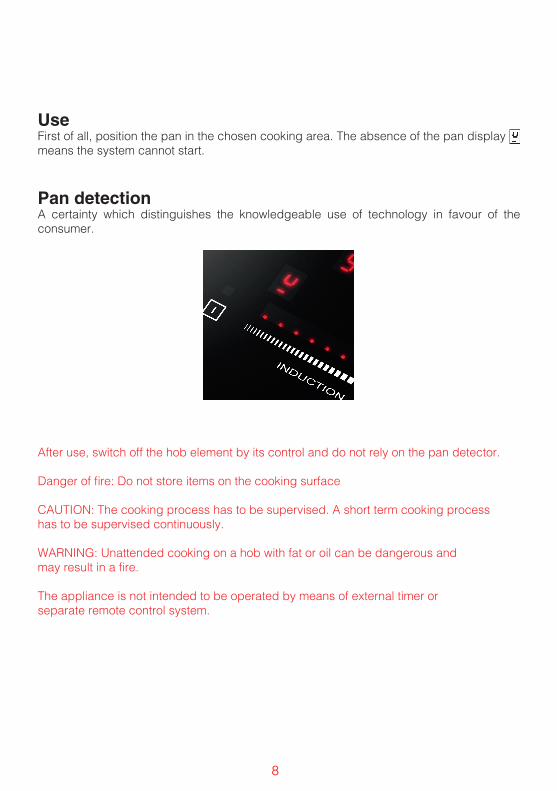
UseFirst of all, position the pan in the chosen cooking area. The absence of the pan display means the system cannot start.
Pan detectionA certainty which distinguishes the knowledgeable use of technology in favour of the consumer.
After use, switch off the hob element by its control and do not rely on the pan detector.
Danger of fire: Do not store items on the cooking surface
CAUTION: The cooking process has to be supervised. A short term cooking process has to be supervised continuously.
WARNING: Unattended cooking on a hob with fat or oil can be dangerous and may result in a fire.
The appliance is not intended to be operated by means of external timer or separate remote control system.

9
P
P
1 ON/OFF2 + Slider Area3 - Slider Area4 Power Booster (P)5 Timer6 Display Value Set7A Display Timer
7B Display Timer8 Pause indicator light9 Timer indicator lights10 Cooking area decimal point11 Power indicator12 LED Strip light13 Pause Fig. 3
FunctionsSwitching the Touch Control ON/OFFAfter switching on the power, the touch control takes about 1 second before it is ready to use. After a reset all displays and LEDs glow for approx. 1 second. When this time is over all displays and LEDs extinguish and the control is in the stand-by mode.By operating the ON/OFF key the control can be turned into the ON-mode. The cooking zone displays show a static “0”. If a cooking zone is in the “hot” status, the display shows a static

10
“H” instead of “=”. The lower right corner of all cooking point displays flash at one-second intervals to indicate that no cooking areas has been selected at the time.After switching ON the electric control remains activated for 20 seconds. If no cooking zone or timer selection follows within this period of time, the electronic control automatically switches back into the stand-by mode.The control can only be switched ON if it identifies the ON/OFF key alone being operated. Should it recognize key activation other than that, the control remains in the stand-by mode.If the child safety feature is active when switching on, all cooking zones show “L” (LOCKED). If the cooking zones are in a “hot” status, the display shows “L” and “H” in alternation.When the Touch Control is ON it can be switched OFF at any time by operating the ON/OFF key. This is also valid if the control has been locked (activated child safety feature).The ON/OFF key has always priority in the switch-OFF function.
Automatic switch-OFFWhen the control is ON it automatically switches OFF after 20 seconds if no cooking zone or select key has been operated within this period of time. In the case of a cooking selection, the automatic switch-OFF time is composed of 10 seconds deselection time for a cooking zone at setting “0” and 10 seconds switch-OFF time.
Hob zone On/OffWith the Touch Control on, a hob zone can be selected by touching the dedicated display (6). The corresponding display them shows the fixed spot on the display and “0” rather than “H” – for very hot hob zones. The spots disappear on the display for all other hob zones.At this point the cooking level can be selected by means of the Slider. In this way the corresponding hob zone is activated. The maximum and minimum values are “9” (to the right) and “0” (to the left).
Turning a single hob zone offA single hob zone can be turned off by selecting a cooking level [0]. If a hot hob zone warning light is on [H], this signal is alternately displayed with [0] and simultaneously with the spot on the display.Once the Touch Control is turned off, the display remains black or the symbol [H] is displayed as a warning of a hot hob zone.Switching OFF all cooking zonesImmediate switching OFF of all cooking zones can be achieved anytime by means of the ON/OFF key. Once the Touch Control is switched off, the display remains off or the system [H] is displayed as a warning that the cooking area is hot.
Switching OFF all cooking zonesImmediate switching OFF of all cooking zones can be achieved anytime by means of the ON/OFF key. In the stand-by mode, an “H” appears on all cooking zones which are “hot”. All other cooking zone displays are not illuminated.

11
Wattage settingsThe output of the cooking zones can be set in 9 steps which are indicated by figures “1” to “9” by means of seven-segment LED displays.
touch control heat intensity1 weak
2-3 gentle4 slow
5-6 medium7-8 strong9 bright
A: INDUCTION COOKING ZONE ø160 LEVEL 9 = 1400W ABOUTMINIMUM START THRESHOLD 700W
B: INDUCTION COOKING ZONE ø200 LEVEL 9 = 2300 W ABOUTMINIMUM START THRESHOLD 1200W
THE ARRANGEMENT OF THE INDUCTORS, RECOGNIZABLE BASED ON THEIR SIZES, ø160, ø200 CAN VARY BUT THEIR BEHAVIOUR MANAGED REMAINS THE SAME Fig. 4
A ø160
B ø200
0
P0
0 P
0P
0 9
00
P
0
P
9 P
00
9 0
8P
0
P
77
0 9
78
0 8
08
9
1
11
1
0
09
P
P
07
8
8
09
8
8
88
0 8
7
8
0
A ø160
B ø200
P Booster functionSelect the cooking zone and then press the Booster button to enter this operating mode.The letter “P” appears on the display the power of the zone increases from rated power to a higher power for 5 minutes: Ø200 - from 2300 to 3000W.This function may terminate ahead of time if:- If you touch the slider area after selecting the cooking area with the “P”.- If the temperature of the zone or system is too high- If the pan is removed for more than 10 minutes

12
Automatic heat-up functionWhen the automatic heat-up function is activated the wattage of the cooking zone is at 100% for a certain heat-up time which is dependent on the setting selected (continuous).At the end of the heat-up time the electronic control switches back to the preselected simmering setting.
Starting process of the automatic heat-up- The control is ON and a cooking zone will be selected- When the power level 9 is reached the automatic heating is activated through a further
press of the slider in correspondence with the maximum value.- The required power level is selected by means of the slider and the selected value is
shown on the display.- At this point, you can select the level required for the continuation of the cooking using the
Slider area. The symbol “A” appears 3 seconds after the button is released, alternating with the continuation level.
- The continuation level can be changed within 15 seconds from activation without disabling the precooking boost. So, you must select the cooking area and then set the corresponding cooking area.
- If the selection takes place after 15 seconds:You can select a higher continuation level; this implies that the precooking time will automatically be aligned to the currently selected continuation level.
Cooking level Precooking Boost A [min] Maximum operating time [h]0 0 0u 0 61 1 62 3 63 4,8 54 6,5 55 8,5 46 2,5 1,57 3,5 1,58 4,5 1,59 0,2 1,5
Residual heat indicatorIt is meant to indicate to the user that the glass ceramic has a dangerous touch temperature in the circumference of a cooking zone. The temperature will be determined following a mathematical model and the remaining residual heat will be indicated by means of “H” on the corresponding 7-segment display.Heating up and cooling down will be calculated dependent on• The selected setting (“0” to “9”)

13
• The ON/OFF time of the relays• After switching OFF the cooking zone the respective display shows “H” until the assigned
cooling zone temperature is mathematically in an uncritical level. (< 60°C).
Automatic switch-off (limited operating time) Maximum operating time is defined for each hob zone. The maximum operating time depends on the selected cooking level (see table). Once the maximum operating time has expired, the hob zone is automatically deactivated.Each activation of the hob zone status (modification of the cooking level etc.) resets the countdown timer up to the initial start value.The timer settings have priority in relation to the operating time limits, namely the hob zone is turned off when the timer has expired and not when requested by the automatic power-off (e.g.: timer of 99 minutes at cooking level 9).
Protection against unintended switching ON. – If the electronic control detects continuous operation of a key for approx. 10 seconds, it switches OFF automatically. The control sends out an audible failure signal for 10 seconds so that the user can remove the object which has been mistakenly placed onto the operation surface. The displays show the failure code “ER03”.
– If the failure carries on for more than 10 seconds, only the code “ER03” will be displayed as long as the failure is detected by the electronic control. If the cooking zone is in the “hot” status, “H” will appear on the display in alternation with the failure signal.
– If no cooking zone is activated within 20 seconds after switching ON by means of the Power-key, the control switches back from the ON condition to stand-by mode.
– When the control is switched ON, the ON/OFF Key has priority over all other keys so that the control can be switched OFF anytime, even in case of multiple or continuous operation of keys.
– In the stand-by mode a continuous operation will not be signalled. However, before the electronic control can be switched ON again, it has to recognize that all keys are not operated.
Child safety lock (childproof function) The child safety lock can only be activated with the Touch Control on if no hob zones are active and no timer has been selected.It is therefore necessary to simultaneously press the hob zone display of the front right hob zone (FR) and the special Power Booster (P), then press the display of the hob area (FR) again. At this point all displays show the symbol [L] denoting LOCKED (=child lock against accidental activation). Any hot hob zones warning lights [H] are shown alternately to the symbol [L].This procedure must be completed within 10 seconds and no other key must be pressed except for that mentioned, otherwise the procedure is cancelled because incomplete.The electronics remain in the locked condition until the key is released, even if in the meantime the control unit was turned off and turned back on again. Reinstatement (disconnecting from the mains) of the command does not remove the lock.

14
Unlocking for cookingThe front right hob zone display (FR) and the special Power Booster (P) must be simultaneously pressed to unlock and prepare the Touch Control unit.The symbol [L] indicating LOCKED disappears from the display. The displays of all the hob zones display [0], together with a flashing dot. Possible hot hob zone [H] warning lights are permanently displayed. After the command unit is turned off, the child safety lock will reactivate again.This procedure must be completed within 10 seconds and no other key must be pressed except for that mentioned, otherwise the procedure is cancelled. Other keys cannot be activated. The power button only can be used (Power) to turn off the Touch Control (and restart the procedure).
Permanent unlockThe hob zone display of the front right hob zone (FR) and the special Power Booster (P) must be simultaneously pressed, then press the special Power Booster again.This procedure must be completed within 10 seconds and no other key must be pressed except for that mentioned. The Touch Control remains in the Off mode (all displays are blank), failing which the procedure is cancelled and the Touch Control switches to Off mode after 20 seconds.If the control unit is activated by pressing the ON/OFF key, all displays will show the “0” symbol, the dots on the display continue to flash and the command unit can be used for cooking. In the presence of the hot hob zone warning lights [H], this message is displayed alternately with [0] and at the same time with the dot on the display.
Acoustic signalling (buzzer)The following activities carried out during the operation of the Touch Control are signalled by a buzzer: – Single brief acoustic signal for the regular activation of a key. The acoustic signal is only emitted on the first activation for the Slider area. No acoustic signal is emitted during the modification of the values.
– A longer intermittent acoustic signal for the permanent use of the keys for a more prolonged period (> 10 seconds
– Timer time-out
Timer function (CL)There are two different types of timer function available: – Independent Timer 1.99 minutes: acoustic signal with timing. This function can be activated only if there are no other hob zones functioning (all levels = 0). If any of the hob zones are activated (level >0) the independent timer remains active. If the timer must be used to switch off a cooking area (see timer for cooking area), then the command must first be turned off and on.
– Hob zone timer 1.99 minutes: This function can be activated as long as a hob is on (level < 0; dot on the display). Four cooking areas to be deactivated are freely programmable timer and beep.

15
Setting a timer value – Adjustment by means of the slider area. – The adjustment of the first digit usually occurs first, followed by the adjustment of the second digit.
– Within 10 seconds after setting the second digit, the value might reset (the dot on the timer display and when there is a specific timer for a hob zone the assigned LED flashing).
– For the display of the active timer, the timer value can be set to [0] by directly pressing [0] on the slider (left side).
Deactivation of an active timer – A timer can be deactivated by setting the value to 0. – An independent timer can be deactivated through the double activation of the power key (1st TC active, 2nd TC and Timers off).
Independent timer – If the control unit is activated (the displays of all hob zones show [0]), the independent timer can be activated by pressing the timer selection key. The display shows 0- and is ready for setting the first digit of the timer. By pressing the timer display, you can go on to programming the second digit of the timer. The timer is disconnected after 10 seconds (blank display) if no other settings are made. If a timer value is set without the activation of a hob zone within 10 seconds, the displays of the hob zones are also disconnected). The hot hob zones warning lights [H] are permanently displayed.
– Until the timer is selected (the dot on the display flashes for 10 seconds), it can be set. The setting range is 0-99 minutes in individual steps, for the Slider area.
– The countdown starts immediately after the timer value has been set, starting from the last set value.
– The timer is automatically deselected after 10 seconds and the time display indicates the timer value. Once the set time has expired, an acoustic signal is activated and the time display shows the flashing symbol “00”.
– The beep stops after 2 minutes and/or by pressing any button. Subsequently, the timer display will stop blinking and switch off. Any hot cooking area warning lights [H] are displayed permanently.
– By pressing the POWER key, the control unit can be switched at any time from the “sole timer function” to a hob zone, with or without an active independent timer.If you switch the Touch Control back to active mode with an independently active timer, first select the independent timer highlighted by the active selection “-”; in this way you can reset it or change its value. If you select a cooking area, the “-” on the display disappears and the time set on the independent timer is displayed. If there is an independent timer set, you cannot program a specific timer for a cooking area. Once a hob zone has been selected, the decimal point on the timer display disappears and a decimal point on the hob zone display flashes. When the control unit is turned off by means of the POWER key, the independent timer (if functioning still) is also turned off.

16
Programming of the specific hob zone timerThe power-on of the Touch Control enables the timer setting for dedicated hob zones. – If you activate a cooking area (cooking area level > 0) and then select the timer display (within 10 seconds), you can assign a value of the timer to the cooking area as a function of switching off the cooking area. The LED corresponding to the timer indicates the hob zone for which the timer has been activated.
– As soon as the timer is selected, one of the LEDs (9) corresponding to the cooking area flashes and the timer shows “0-” indicating that the first digit of the timer can be programmed using the slider area. Once you have set the first digit, pressing the timer display allows you to set the second digit.
– When switching from one hob zone to another, the timer display shows the current timer value of the related hob zone. The timer setting of the other hob zones remain active.
– The other settings are the same as those for the independent timer. – If more than one timer is active, the display shows the value of the lowest timer (after a deselection time of 10 seconds).
– After the set time has expired, an acoustic signal is activated and the timer display shows the flashing “00” symbol. The LED of the corresponding timer flashes at the same time. The cooking area programmed turns off and the symbol “0” is displayed fixed. The symbol “H” is displayed after 10 seconds (deselection time) in correspondence with a hot hob zone (“hot”). Otherwise the symbol “0” is displayed.
– The acoustic signal and flashing hob zone LED stop after 2 minutes and/or activating any key.
At this point the displays disappear and the hob zone remains deselected.The behaviour of the specific hob zone timer is similar to that of the independent timer.If a timer is programmed for a hob zone, the limitation of the operating time depend on the timer value and not on the value of the standard table.The precision of the timer value depends on the precision of the clock μC that can deviate by +/- 4% in 99 minutes.
Food warmer function (optional)The food warmer function keeps the food on a hob zone warm.In this case the selected hob zone is activated at low power.When the food warmer function is activated for a hob zone, the corresponding display indicates the “u” symbol (see symbols).
Activation/DeactivationThe food warming function can also be activated as an additional cooking level between 0 and 1.To use the foodwarmer function, select an area, set it to 1 using the slider and then immediately to 0. For the operating times, see the table.
Time limitation of the heat holding functionFor microbiological reasons, the food warming function should not be used for excessively prolonged periods (maximum 1 hour. For this reason the Touch Control automatically

17
switches off after 2 hours).
PAUSE Activation of the pause function When at least one hob zone is functioning, the heating elements can be deactivated by pressing the Pause key.The pause display has priority.The timers that have already been programmed (also for the independent timer) are stopped and do not function during the pause time. The automatic heater and booster are also deactivated on all the hob zones during the activation, while the calculation of the residual heat and the limitation of the operating time continues to function without being stopped.The LEDs of the other functions (timer) remain on depending on their status.The pause can last up to 10 minutes. If it is not terminated within this time interval, the command is deactivated. The hob zone can be switched at any time by means of the On/Off key. Any active pause functions are in this way terminated.
Termination of the Pause functionTo terminate the Pause mode and start the operation again, the Pause key and any other key (not the same key again) must be activated within 10 seconds.In this way the function existing before the Pause is re-established. If no other key is activated within the 10 seconds, the hob zone is also switched off.
Additional functions of the pause LEDThe indicator light behaves in the following way:When the Pause function is deactivated, the LED remains off. When the pause function is activated, the LED remains on. The LED flashes during the waiting time before a second key is pressed. The LED also flashes if the supplementary recall function is possible after restart.Recall (optional for the multifunction key)The settings can be quickly recovered after power-off by means of the power key, the operator has 6 seconds to activate the Pause key. This function can only be performed if it was previously active andwas confirmed by an acoustic signal of the key.The following operations are restored: – cooking level of all hob zones – minutes and seconds of the programmed hob zone timers – switching conditions of the external circuits (guaranteed by the reminder function of the external circuit)
– heat-up functionThe following operations are not restored: – limitation of the timer time (the operator deactivated it) – timer operating cycle (a new cycle is started after restart) – If the delay time of a power reduction is running when switching off (power management), but the new cooking level has not yet been detected, the recall may not restore the last setting of the operator (to be executed as a priority). This particular case can only occur

18
during the 3 seconds delay time of reduced power.Note: If there is even a slight crack in the cooking surface, immediately disconnect the power.
MaintenanceFirst of all remove stray food bits and grease drops from the cooking surface with the special scraper. Then clean in the cooking area with specific products for vitroceramic cooking surfaces and a paper towel and then rinse with water and dry with a clean cloth.Pieces of aluminium foil and plastic material which have inadvertently melted or sugar remains or food with a high saccharine content have to be removed with the special scraper. This is to avoid any possible damage to the surface of the top. Under no circumstances should abrasive cones or irritating chemical detergents, such as oven sprays or stain removers, be used.
DO NOT USE STEAM CLEANERS
Fig. 6 Fig. 7
NO NO YES
19
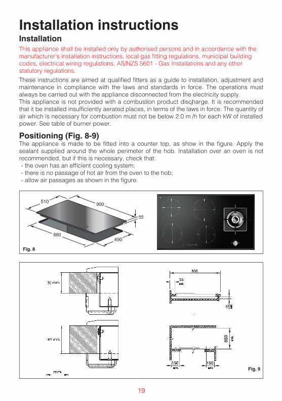
Installation
These instructions are aimed at qualified fitters as a guide to installation, adjustment and maintenance in compliance with the laws and standards in force. The operations must always be carried out with the appliance disconnected from the electricity supply.This appliance is not provided with a combustion product discharge. It is recommended that it be installed insufficiently aerated places, in terms of the laws in force. The quantity of air which is necessary for combustion must not be below 2.0 m
3
/h for each kW of installed power. See table of burner power.
Positioning (Fig. 8-9)The appliance is made to be fitted into a counter top, as show in the figure. Apply the sealant supplied around the whole perimeter of the hob. Installation over an oven is not recommended, but if this is necessary, check that: - the oven has an efficient cooling system;- there is no passage of hot air from the oven to the hob;- allow air passages as shown in the figure.
Fig. 8
Fig. 9
Installation instructions
This appliance shall be installed only by authorised persons and in accordance with themanufacturer's installation instructions, local gas fitting regulations, municipal building codes, electrical wiring regulations, AS/NZS 5601 - Gas Installations and any other statutory regulations.

20
Fig. 10
56
4.8
900R 10
510
880 0+1
490
0 +1
POSIZIONE GUARNIZIONE SIGILLANTENELLA VERSIONE SEMIFILOTOP
POSITION OF SEALANT IN THE SEMIFILOTOP VERSION

21
Gas connection (Fig. 11)Connect the appliance to the gas cylinder or to the installation according to the prescribed standards in force, and ensure beforehand, that the appliance matches the type of gas available. Other wise, see ”Adaptation to various types of gas”. Further more, check that the feed pressure fall swithin the values described on the table: ”User chacteristics”.
Fig. 11
There are two ways to carry out the connection to the main gas line:A. The hotplate can be connected with rigid pipe as specified in AS/NZS5601.B. The hotplate can be connected with a Flexible Hose, which complies with AS/NZS 1869 (Australian Certified), 10mm ID, class B or D, no more than 1.2m long and in accordance with AS/NZS 5601. Ensure that the Hose does not contact the hot surfacesof the hotplate, oven, dishwasher or other appliance that may be installed underneath or next to the hotplate. WARNING: Ensure that the hose assembly is restrained from accidental contact with the flue or flue outlet of an underbench oven. The hose should not be subjected to abrasion, kinking or permanent deformation and should be able to be inspected along itsentire length. Unions compatible with the hose fittings must be used and connections testedfor gas leaks. The supply connection point shall be accessible with the appliance installed. The hose assembly shall be suitable for connection to a fixed consumer piping outlet located at a point 800mm to 850mm above the floor and in a region outside the width of the appliance to a distance of 250mm.
Adaptation to varius types of gas (Fig. 12)Should the appliance be pre-set for a different type of gas than available, procreed as follows:• replace the injector (Fig. 13) with the corresponding type of gas to be used (see table
“User characteristics“);• to adjust to the minimum, use a screwdriver on the screw placed on the tap (Fig. 13) after
turning the tap to its minimum position. For GPL (butane/propane) screw tight.
A
B
Fig. 12
Data LabelThe Data Label is located on the base of the appliance. A duplicate Data Label is supplied to adhere in an accessible area next to theappliance. This appliance is suitable for Natural Gas and ULPG; ensure that the available gas supply matches the Data Label.

22
Fig. 13
USER CHARACTERISTICS
GAS BURNERS
FEEDTYPE PRESSURE mbar
NORM.BURNER Ø INJECTORS
1/100THERMAL CAPACITY CONSUMPTION
Natural gas - 1.00 kPa Wok DualA - Ø0.80 inner
4000 17.5 MJ/hB - Ø1.30 outer
Universal LPG - 2.75 kPA Wok Dual
A - Ø0.48 inner4000 16.0 MJ/h
B - Ø0.70 outer
Electrical connectionBefore connecting to the electricity supply, ensure that: - the characteristics of the system are such as to satisfy that indicated on the registration plate
applied to the bottom of the hob;- the system has an effective earth connection compliant with the standards and laws in force.
Connection to earth is compulsory by law. If the appliance has no cable and/or plug, use material suitable for the absorption indicated on the registration plate and for the working temperature. The cable must not reach a temperature higher than 50°C above room temperature in any point. For direct connection to the network it is necessary to fit an omnipolar switch of a suitable size to ensure disconnection of he network with a contact opening distance that allows complete disconnection in the conditions of the overtension category III, compliant with the installation regulations (the yellow/green earth wire must not be interrupted). The omnipolar socket or switch must be easy to reach when the appliance is installed. N.B.: - The manufacturer declines all responsibility if the usual accident prevention standards and
the above instructions are not observed. If the power cable is damaged, it must be replaced by the manufacturer or by the manufacturer’s
.ksir elbissop yreve tneverp ot ,rotarepo defiilauq ylralimis a yb ro ,krowten gnicivres lacinhcet
Before LeavingCheck all connections for gas leaks with soap and water. DO NOT use a naked flame for detecting leaks. Ignite the burner to ensure correct operation of gas valve, burner and ignition. Turn gas tap to low flame position and observe stability of the flame. When satisfied with the hotplate, please instruct the user on the correct method of operation. In case the appliance fails to operate correctly after all checks have been carried out, refer to the authorised service provider in your area.

23
aria - air - air - Luft - aire - lucht - ar
100 cm2 MIN.induzione - induction - induction - Induktion- inducción - inductie - indução
aria - air - air - Luft - aire - lucht - ar
100 cm2 MIN.
ZONA FORNO O ARMADIETTOOVEN ZONE OR CUPBOARD
ZONE FOUR OU PLACARDOFENBEREICH ODER SCHRANK
ZONA HORNO O ARMARIO
OVENRUIMTE OF KASTJEZONA DO FORNO OU ARMÁRIO
50 MIN.
50 MIN.
20 M
IN.
N
L
PE
N
L2
L1
PE
Fig. 14
Fig. 15

24
Error code description Possible causes Error recovery
C The cooking zone can be configured if a static “C” is shown.
It’s not an error, the user is in the serivice menu.
A suitably pan must be placed on the relevant cooking zone.
C/- The cooking zone will be configured if a blinking “C” is shown. After a successful configuration the relevant display shows “-”.When the “-” is not displayed please check the possible causes of the E/5.
The user is in the service menue, it’s not an error.
Wait for the sysmbol “-” or abort the configuratuib activities by pressing the selectkey and the “C” does not blink anymore.
2. over voltage. Exchange the module.
E/7 Non assignable failure. Exchange module or User Interface.
E/8 Fan failure. Fan or control electronic is defect.
Exchange the modul .
E/9 Defect T sensor on inductor.
Sensor signal out of valid range; sensor or electronic is defect.
Exchange the modul .
E/A Hardware defect of induction module.
Defect hardware device detected by the self check of the module.
Exchange the modul .
E/C Configuration failure. 2 cooking zone are dedicated to the same element of the UI.
1. Erase the actual configuration manual with service menù.
E/H Fixed sensor value (test function for T sensor on inductor).
Not enough temperature change (10K) within 5 min after switch on the hob.
Systerm must cool down.
No functionality and no displaying
Overvoltage on the switch mode power supply (jno fuctionality).
400V connection. Disconnet and correct the power line connection.
E A blinking “E” on each cooking zone indicates, that all configs will be.
The user is in the service menù, it’s not an error.
Manual configuration.
E/2(Error code different for some UI)
Temperature limits are excessed.
1. Pot or glas temperature is to2. NTC - electronik temperature to high.
System must cool down.

25
Error code description Possible causes Error recovery
E/3 Unsuitable pot, e.g. lost of the magnetic characteristics because of temperature in the bottom.
Pot creates on the module an improper operating point which can destroy devices, e.g. IGBT.
1. the error is automaticly cancelled after 8s and the cooking zone can be used again. In case of further upcoming errors the post have to be changed.2. the module has to be changed if the error comes without an pot on the cooking zone.
E/4 Unconfigured induction
Any of the following are considered to be abnormal operation and may require servicing:Yellow tipping of the hob burner flame.Sooting up of cooking utensils.Burners not igniting properly.Burners failing to remain alight.Burners extinguished by cupboard doors.Gas valves, which are difficult to turn.In case the appliance fails to operate correctly, contact the authorised service provider in your area”.
module answer to UI, but any element is related to the effected cooking zone).
Induction module is not configured.
1. Delete the hob configuration and activate the manual configuration.2. Start the UI service menue to configure the induction module.3. If the listed points are not succesful replace the module.
E/5 No communication between UI and induction module.
No power supply of induction moduleMal cable or defect of.
Check power and line connections is the connention ok, replace the module.
E/6 Main power disturbance . 1. Failure in main power frequency detection.
Check main power voltage and frequency, if ok.
Abnormal Operation
Unsustable pot, e.g.

EUROLINX LIMITED WARRANTY
Eurolinx Pty Limited A.B.N. 50 001 473 347 Office: 48-50 Moore Street, Leichhardt N.S.W 2040 Post: Locked Bag 3000, Annandale, N.S.W 2038P: 1300 694 583
WARRANTY REGISTRATIONYour ongoing satisfaction with your product is important to us. We ask that you complete the enclosed Warranty Registration Card and return it to us so that we have a record of the products you purchased. Alternatively you can register on line (see registration card for details)
PRIVACYWe respect your privacy and is committed to handling your personal information in accordance with the National Privacy Principles and the Privacy Act 1988 (Cth). A copy of the Privacy Policy is available at www.eurolinx.com.au. Eurolinx will not disclose any personal information set out in the Warranty Registration Card (“Personal Information”) without your consent unless required by:1. law;2. any Eurolinx related company;3. any service provider which provide services to Eurolinx or assist Eurolinx in providing services (including repair and warranty services) to customers. Our purpose in collecting the Personal Information isto keep a record of the Eurolinx product purchased by you, in order to provide a better warranty service to you in the unlikely event that there is a problem with your Eurolinx product. Eurolinx may contact you at any one or more of the address, email address or telephone numbers set out in the Warranty Registration Card. Please contact Eurolinx on 1300 694 583 should you not wish to be contacted by Eurolinx.
WARRANTY1. WarrantyEurolinx warrants that each Eurolinx product will remain, for a period of twenty four (24) months computed from the date of purchase of the Eurolinx product, free from defects arising in the manufacture of the Eurolinx product (“Warranty”). Except for consumer guarantees set out in the Competition and Consumer Act 2010 (Cth) (“Act”), Eurolinx does not make any further warranties or representations in relation to Eurolinx products.2. What is not Covered by the Warranty.The Warranty does not apply if an Eurolinx product is defective by a factor other than a defect arising in the manufacture of the Eurolinx product, including but not limited to:
(a) damage through misuse (including failure to maintain, service or use with proper care), neglect, accident or ordinary wear and tear (including deterioration of parts and accessories and glass breakage);(b) use for purpose for which the Eurolinx product was not sold or designed;(c) use or installation which is not in accordance with any specified instructions for use or installation;(d) use or operation after a defect has occurred or been discovered;(e) damage through freight, transportation or handling in transit (other than when Eurolinx is responsible);(f ) damage through exposure to chemicals, dusts, residues, excessive voltage, heat, atmospheric conditions or other forces or environmental factors outside the control of Eurolinx;(g) repair, modification or tampering by the purchaser or any person other than Eurolinx, an employee of Eurolinx or an authorised Eurolinx service contractor;(h) use of parts, components or accessories which have not been supplied or specifically approved by Eurolinx.(i) damage to surface coatings caused by cleaning or maintenance using products not recommended in the Eurolinx product handbook provided to the purchaser upon purchase of the Eurolinx product;(j) damage to the base of an electric oven due to items having been placed on the base of the oven cavity or covering the base, such as aluminium foil (this impedes the transfer of heat from the element to the oven cavity and can result in irreparable damage); or(k) damages, dents or other cosmetic imperfections not affecting the performance of the Eurolinx in respect of an Eurolinx product purchased as a “factory second” or from display. The Warranty does not extend to light globes used in Eurolinx products.3. Domestic UseEach Eurolinx product is made for domestic use. This Warranty may not extend to Eurolinx products used for commercial purposes; under those circumstances the warranty period is limited to 3 month.4. Time for Claim under the WarrantyYou must make any claim under this Warranty within twenty eight (28) days after the occurrence of an event which gives rise to a claim pursuant to the Warranty, by booking a service call on the telephone number below.5. Proof of PurchaseCustomers must retain proof of purchase in order to be eligible to make a warranty claim in respect of an Eurolinx product.
Continued over...

6. Claiming under the WarrantyCustomers will bear the cost of claiming under this Warranty unless Eurolinx determines the expenses are reasonable, in which case the customer must claim those expenses by providing written evidence of each expense to Eurolinx at the address on the Warranty Registration Card.
7. Statutory Rights(a) These terms and conditions do not a ect your statutory rights.(b) The limitations on the Warranty set out in thisdocument do not exclude or limit the application of theconsumer guarantees set out in the Act or any otherequivalent or corresponding legislation in the relevantjurisdiction where to do so would:(i) contravene the law of the relevant jurisdiction; or(ii) cause any part of the Warranty to be void.(c) Eurolinx excludes indirect or consequential loss of any kind (including, without limitation, loss of use of theEurolinx product) and (other than expressly provided for in these terms and conditions) subject to all terms,conditions and warranties implied by custom, the general law, the Act or other statute.(d) The liability of Eurolinx to you for a breach of any express or non-excludable implied term, condition orwarranty is limited at the option of Eurolinx to:(i) replacing or repairing the defective part of the Eurolinx product;(ii) paying the cost of replacing or repairing the defective part of the Eurolinx product;(iii) replacing the Eurolinx product; or(iv) paying the cost of replacing the Eurolinx product.(e) Our goods come with guarantees that cannot be excluded under the Australian Consumer Law.
You are entitled to a replacement or refund for a major failure and for compensation for any other reasonablyforeseeable loss or damage. You are also entitled to have the goods repaired or replaced if the goods failto be of acceptable quality and the failure does not amount to a major failure.
8. DefectsAny part of an Eurolinx product deemed to be defective and replaced by Eurolinx is the property of Eurolinx. Eurolinx reserves the right to inspect and test Eurolinx products in order to determine the extent of any defect and the validity of a claim under the Warranty.*To locate your closest Eurolinx authorised service agent please contact Eurolinx on 1300 649 583, [email protected] or visithttp://support.eurolinx.com.au
IMPORTANT!All warranty service calls must be booked via the customer care department. The team can be contacted on 1 300 85 64 11 option 1 or [email protected] is delivered through a network of Service Agents. If the Appliance is located outside our normal Service Area of our agents you, t he Customer will need to bear the cost of travel outside that area.If you are unable to provide proof of purchase, the fault is not covered under warranty or the product is found to be working to specification you may be required to bear the full cost of the service visit
08042016
EUROLINX LIMITED WARRANTY
Please complete and send to Eurolinx at: REPLY PAID 83617 LEICHHARDT NSW 2040
Last Name: First Name:
Address:
State: Postcode: Email:
Home Phone: Mobile:
Purchase Date: / / (Please attach proof of purchase to validate warranty)
MODEL NUMBER SERIAL NUMBER (if you cannot locate the serial number please call Eurolinx on 1300 85 64 11)
1
2
3
4
WARRANTY REGISTRATION CARD08042016

(\Z[YHSPH�5H[PVUHS�;LSLWOVUL�5\TILY������4@03=,��� ������5L^�ALHSHUK�;LSLWOVUL�5\TILY������������
03=,�ZOV^YVVTZ�HYL�VWLU�KHPS`�MYVT� HT��WT�HUK�:H[\YKH`Z���HT��WT �>(�I`�HWWVPU[TLU[�VUS`�VU�:H[\YKH`Z� PS]L�JVT�H\
5:>� �(*;��/LHK�6ɉJL�������4VVYL�:[YLL[� 3LPJOOHYK[-������� ���
=0*��;(:� �:(�����;VVYHR�9VHK� *HTILY^LSS-���� �� �����
83+�����*H]LUKPZO�9VHK�*VVYWHYVV�-������ ������
>(� �5;<UP[�������/V^L�:[YLL[6ZIVYUL�7HYR�-���� ���� ���
5L^�ALHSHUK76�)V_�������:VJRI\YU�*OYPZ[JO\YJO-��������� ��


![Untitled-1 [steelmarketinfo.com]€¦ · INDUCTION COOKTOPS LPG COOKTOPS WATER HEATERS CHIMNEYS I HOBS LPG COOKTOPS I KITCHEN SINKS WATER HEATERS OFFICE CHAIRS LUXURY MASSAGE APPARATUS](https://static.fdocuments.us/doc/165x107/5f0683737e708231d4185d88/untitled-1-induction-cooktops-lpg-cooktops-water-heaters-chimneys-i-hobs-lpg.jpg)