Instruction Manual for Clarification fo Startup in Source ...
146
Un ited States Environmental Protection Agencv Office of Enforcement EPA-68-01-41-13 Office of General Enforcement October 1979 Division of Stationary Source Washington, DC 20460 Enforcement EPA Instructional Manual for Clarification of Startup in Source Categories Affected by New Source Performance Standards MAY -5111 1200 SixtI'I Avenue. 81_ WA 88*
Transcript of Instruction Manual for Clarification fo Startup in Source ...

Un ited States Environmental Protection Agencv
Office of Enforcement EPA-68-01-41-13 Office of General Enforcement October 1979 Division of Stationary Source Washington, DC 20460 Enforcement
EPA Instructional Manual for Clarification of Startup in Source Categories Affected by New Source Performance Standards
MAY -5111 1200 SixtI'I Avenue. 81_ WA 88*


U.S. ENVIRONMENTAL PROTECTION AGENCY Washington, D.C. 20460
GCA-TR-79-33-G
EPA Project Officer
John Busik
EPA Task Manager
Robert Myers Division of Stationary Source
Enforcement Division of Stationary Source
Enforcement 401 M Street, S.W.
Washington, D.C. 20460 401 M Street, S.W.
Washington, D.C. 20460
Contract No. 68-01-4143 Technical Service Area 1
Task Order No. 62
INSTRUCTIONAL MANUAL FOR CLARIFICATION
OF STARTUP IN SOURCE CATEGORIES
AFFECTED BY NEW SOURCE
PERFORMANCE STANDARDS
Final Report
October 1979
by
Douglas R. Roeck Peter H. Anderson Philip S. Hineman Robert G. McInnes William F. Ostrowski

DISCLAIMER
This Final Report was furnished to the Environmental Protection Agency by GCA Corporation, GCA/Technology Division, Burlington Road, Bedford, Massachusetts 01730, in fulfillment of Contract No. 68-01-4143, Technical Service Area 1, Task Order'No. 62. The opinions, findings, and conclusions expressed are those of the authors and not necessarily those of the Environmental Protection Agency. Mention of company or pToduct names is not to be considered as an endorsement by the Environmental Protection Agency.

ABSTRACT
New Source Performance Standards promulgated for 27 source categories specify that performance testing shall be conducted within certain time .periods of startup for each affected facility. This manual discusses initial startup for each new facility subject to these regulations and provides the technical basis for uniform application of the regulations pertaining to source testing.
iii

Abstract • Figures
1.
2.
CONTENTS
Introduction and,Summary ••••••••••• Inttloduction Summary • • • • •
Industrial Summaries Source Listing Fossil Fuel-Fired Steam Generators - Subpart D
160.40 - 60.46 • • • . • Incinerators ~ Subpart E
160.50 - 60.54 •.•• Portland Cement Plants - Subpart F
160.60 -60.64 •••..••• Nitric Acid Plants - Subpart G '
160.70 - 60.74 ..••..•. Sulfur·ic Acid Plants - Subpart· H
160.80'- 60.85 •••.• Asphalt Contrete Plants - Subpart I
160.90 - 60.93 •••..•.•• Petroleum Refineries - Subpart J
160.100 - 60.106 ••••...
. . .'
Storage Vessels for Petroleum Liquids - Subpart K 160.110 - 60.113 .•••..
Secondary Lead Smelting - Subpart L 160.120 - 60.123 •••••••.•
Secondary Brass and Bronze Ingot Production Plants -
iii vii
1 1 2 4 4
6
10
14
20
25
29
35
42
44
Subpart M 160.130 - 60.133 48 Iron and Steel Plants - Subpart N
160.140 - 60.144 . • • • • . 53 Sewage Treatment Plants - Subpart 0
160.150 - 60.154 .•..• Primary Copper Smelters- Subpart P
160.160 - 6u.168 Primary Zinc Smelters - Subpart Q
160.170 - 60.176 Primary Lead Smelters - Subpart R
160.180 - 60.186 •••• Primary Aluminum Reduction Plants - Subpart S
160.190 - 60.f95 •• • . • • ••..•.. Wet Process - Phosphoric Acid Plants - Subpart T
160.200 - 60.204 •• • • • • . . . . • • . . • .
v
57
63
69
74
. . . 80
85

CONTENTS (continued)
Superphosphoric Acid Plants - Subpart U 660.210 ~ 60.214 .••...•••.•
Diammonium Phosphate Plants - Subpart V 660.220 - 60.224- .•••..•...
Triple Superphosphate Plants - Subpart W 660.230 - 60.234 •.•.....••
. . .. .
Granular Triple Superphosphate Storage Facilities -Subpart X 660.240 - 60.244 . . • •
Coal Preparation Plants - SUbpart Y 660.250 - 60.254 •••.•.••
Ferroalloy Production Facilities - Subpart Z 660.260 - 60~266 •••••.•
Iron and Steel Plants: Electric Arc Furnaces Subpart AA 660.270 - 60.275
Kraft Pulp Mills - Subpart BB 660.280 - 60.285 .•.••
Grain Elevators - Subpart DD 660~300 - 60.304 .•.•••
Lime Manufacturing Plants - Subpart HH: 660.340 - 60.344 •.•.•••••••
vi
89
94
. . . 98
• 102
• • 105
· 108
• 113
• 116
124
• • 129

FIGURES
-Number
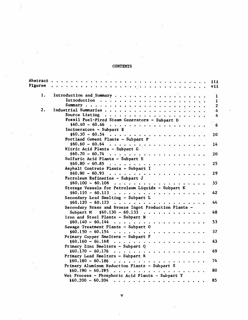
1 Simplified flow diagram of a fossil fuel-fired steam generator • • • • • •• •••• • . . . . . . . . 7
2 Schematic diagram for a continuous feed municipal incinerator • • • • • • • . . . . • . • • 11
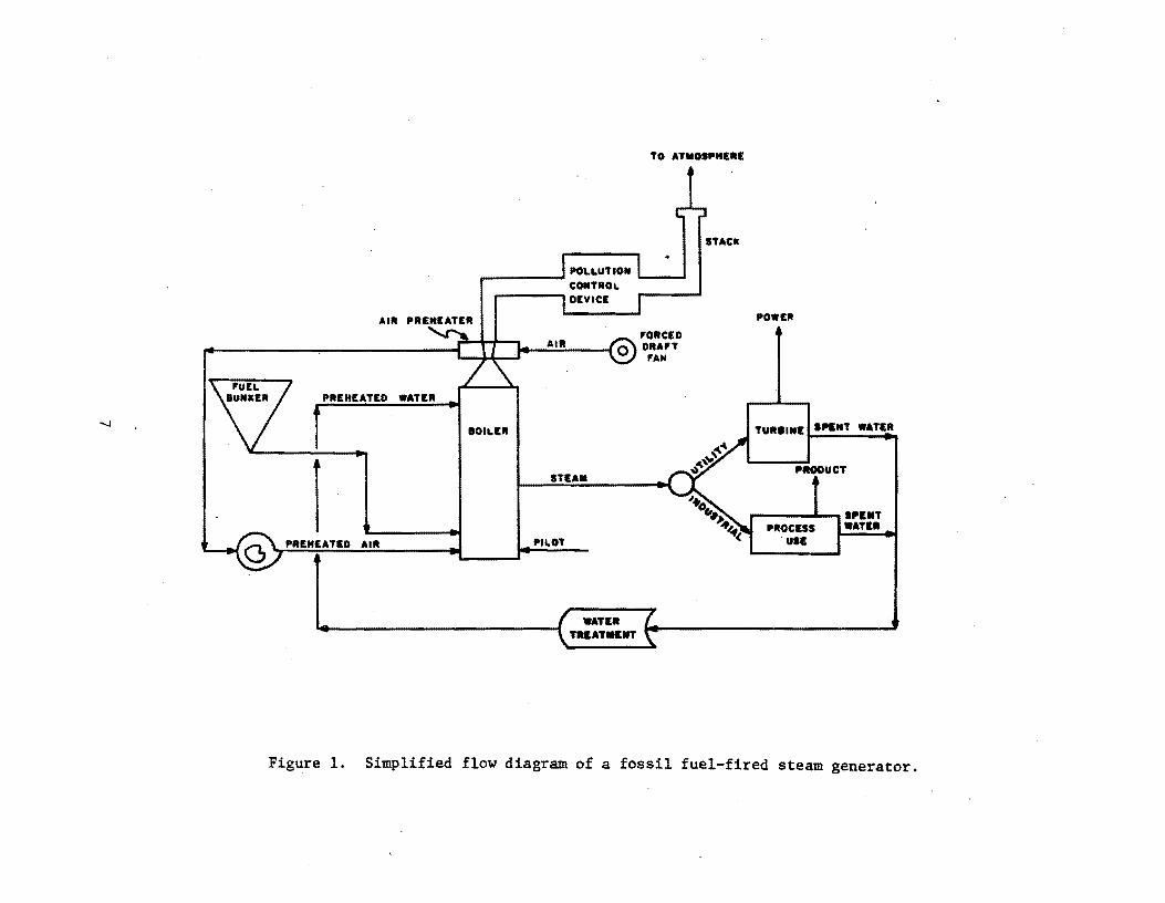
3 Conventional dry process cement plant . . .. . . 15
4 Suspension preheater cement plant • • . . . . . . . . • 16 I
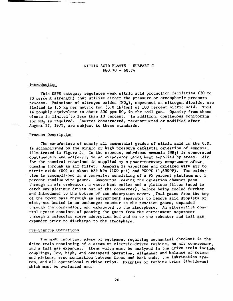
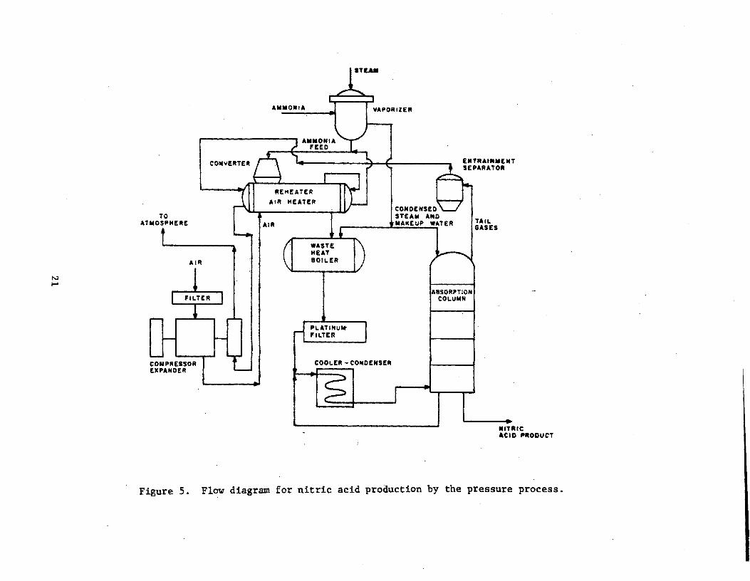
5 Flow diagram for nitric acid production by the pressure process . . . . . . . . . . . . . . . . . . 21
6 Schematic diagram of two processes for manufacturing sulfuric acid • • • • • • • • • • • • • • • • • • • . . . . . . 26
7 Schematic diagram of a typical batch asphalt concrete t:'lant . . . . • . . . . . . . . • . . . .. .... 31
8 Flow diagram for catalytic cracking process • •.• • 36
9 Flow diagram for a typical three-stage claus sulfur recovery plant •••••••••• • • • • 39
10 BraSB and bronze ingot production facility 49
11 BOPFSteelmaking process flow diagram • • • 54
12 Sewage sludge incinerator process diagram • • • • • 58
13 Sewage sludge wet air oxidation process diagram • 59
14 Flow diagram for copper smelting and various unit processes • • • • • • • • • • 64
J5 The pyrometallurgical process • . . . 71
16 l.ead smelting flow diagram with typical process units • • 75
17 l'rclcess flow diagram for primary aluminum reduction • • • • • • • 81
vii

FIGURES (continued)
Number
18 Flow diagram of the "ret-process phosphoric acid production process. • • • • • • • • • • • • • • .86
19 Superphosphoric acid production by the vacuum evaporat ion process • • • • • • • • • • • • • • • • • •• 90
20 Superphosphoric acid production by the submerged . combustion process ••••• •• • • • • • • • . . 91
21 Process flow diagram for diammonium phosphate production 95
22 Flow diagram for triple superphosphate manufacturing process . . . . . . . . . . . . . . . 99
23 . Granular triple superphosphate storage plant . . . . 103
24 Schematic diagram of the ferroalloy production process • • • •• 110
25 Flow diagram for Kraft pulping process operation • 118
26 Process flow diagram for grain terminal elevators 126
27 Process flow diagram fot lime cal~ination and llydrat ion . . . . . . . . . . . . . • • . . . . . . . . . . . 130
viii

· ACKNOWLEDGMENT
The authors wish to thank Mr. Robert Myers, the EPA Task Manager, for his guidance throughout the program. We acknowledge Mr. Norman Surprenant of GCA/TechnologyDivision, who provided a critical review of this document. Finally we would like to thank Mr. Paul Exner of GCA -for his contribution to the manual.


SECTION 1
INTRODUCTION AND SUMMARY
INTRODUCTION
Since 1971, New Source Performance Standards (NSPS) have been promulgated by the U.S. Environmental Protection Agency for twenty-seven (27) industrial categories. Section 60.8 of Title 40 of the Code of Federal Regulations (CFR) specifies conditions for conductance of performance tests for determining compliance with the regulations. Paragraph(a) states in part that performance tests are to be conducted "within 60 days after achieving the maximum production rate at which the affected facility will be operated, but not later than 180 days after initial startup of such facility ••• " Startup is defined under Part 60.2, paragraph (0), as "the setting in operation of an affected facility for any purpose." The general nature of this definition could result in a nonuniform interpretation of "startup" by enforcement personnel as applied to various source categories.
The purpose of this manual, therefore, is to provide .concise, descriptive summaries of the regulated industries including all operations and procedures related to the startup of a new facility. These industrial "profiles" will provide a common .basis upon which decisions can be made with respect to the proper time for performance testing. This is an important decision since testing at less than optimum conditions can yield erroneous and unrepresentative results as well as incurring additional costs upon tne source operator.
LIMITATIONS
This manual should not be used as a substitute for meeting NSPS require~ ments as presented in the Federal Register or Code of Federal Regulations, since the summaries in this manual do not contain all of the requirements a source must meet in performance testing. Additionally, new standards are nearing promulgation and current standards are being revised; this manual represents standards in effect only through March, 1979.
EFFECTIVE·DATE
Each source section in this manual contains an effective date. Any source in that category constructed, reconstructed or modified after the effective date is subject to the applicable NSPS.
1

PROJECT APPROACH
Technical information for this manual has been solicited primarily from process engineers employed at the industries involved. Additional data have been obtained from trade associations, equipment suppliers or contractors, and technical journals and publications.
ArPLICATION OF FINDINGS
The startup definitions specified for each industry have been geared towards normal or typical circumstances in wh'ich all equipment is delivered and tested on schedule and no major malfunctions occur during initial startup or subsequent process'evaluation. This manual points out several source categories where problems might be encountered in meeting the 180 day deadline. In these instances, enforcement personnel will evaluate the situation on a case-by-case basis. It must be, stressed that not obtaining maximum production rate within 180 days (as may occur with the kraft pulp mill, nitric acid plant, or prim8.ry aluminum industry, for example) is not sufficient reason for delay of performance tests; tests could be required during the 180 day period and again when maximum production is reached.
SUl'fM,ARY
, Contacts with the various industries involved in each of the NSPS categories have resulted in many similar circumstances regardless of source type, which affect new source startup. Items which generally apply to any source category are:
• The desire to come on-stream as soon as possible so as to minimize extensive startup periods which would result in excessive capital expenditures with no immediate cash flow return.
• Training of operating personnel can be very important if experienced people cannot be obtained from another plant location.
• Most plants initially undergo mechanical acceptance of process equipment which is partially carried out by the contractor or equipment supplier and partially carried out by the source owner or operator.
• Following mechanical acceptance, process performance evaluation is conducted, usually in the form of a demonstration or test run, resulting in the acceptance of the plant from the contractor.
Some specific procedures or operations that may be carried out for particular pieces of equipment are:
• Water batching of liquid vessels for leak detection and instrument calibration,
• Gradual firing and curing of equipment containing refractory material,
2

• Hydrostatic or pressure testing of fossil fuel-fired vessels according to specific codes, and
• Dry operation of mechanical mixing, ·granulating, conveying, and transporting systems.
Other aspects of plant startup which regulatory people need to be familiar with pertain to the phenomenon of engineering scale. Scale-up problems are bound to occur since most new plants tend to be larger in capacity than existing ones and also attempt to incorporate innovative designs relative to energyefficiency. New facilities constructed for a known process of nominal design production rate would likely require much less time than a new plant built for a prototype process or a much larger plant.
The Industrial surveys conducted have resulted in several common suggestions for definition of an initial plant startup, irrespective of the industry involved:
1. 24-hours of continuous operation
2. Shipment of on-grade product to the customer
3. Product from process is used to make a profit or is inventoried.
4. First introduction of raw material with potential for emis'sion of regulate.d pollutant(s)
- .5. Mechanical acceptance of plant
6. Completion of successful demonstration run
7. Contractual acceptance of plant
The selection of startup for each industry has been based upon a composite of three criteria; the theoretical position of an enforcement agency (No.4 above), the viewpoint of industrial contacts (all of the above), and the ability of a source category to achieve rated capacity within 180 days of the selected startup point.
GOOD AIR POLLUTION CONTROL PRACTICE DURING STARTUP
After the effective date of an NSPS, an applicable source must meet the -standard except during times of startup, shutdown, or malfunction. The source owner or operator must at all times, including startl:lp, maintain and operate any affected facility in a manner consistent with good air pollution control practice (40 CFR 60.11(d». Hence, atmospheric emissions during the startup period must always be directed through pollution control equipment.
3

SECTION 2
INDUSTRIAL SUMMARIES
SOURCE LISTING
The twenty~seven (27) source categories currently affected by NSPS which are the subject of this report are listed as follows:
1. Fossil fuel-fired steam generators
2. Incinerators
3. Portland cement plants
4. Nitric acid plants
5. Sulfuric acid plants
6. Asphalt concrete plants
7. Petroleum refineries
8. Storage vessels for petroleum liquids
9. Secondary lead smelters
10. Secondary brass and bronze ingot production plants
11. Iron and steel plants
12. Sewage treatment plants
13. Primary copper smelters
14. Primary zinc smelters
15. Primary lead s~e1ters
16. Primary aluminum reduction plants
17. Wet-process phosphoric acid plants
18.· Superphosphoric acid plants
19. ]}iammonium phosphate plants
20. Triple superphosphate plants
21. Granular triple superphosphate plants
22. Coal preparation plants
23. r'erroalloy production facilities

24. Steel plants: electric arc furnaces
25. Kraft pulp mills
26. Grain elevators
27. Lime manufacturing plants
The detailed summaries that follow are arranged in the same order as the preceding list and as they appear inCFR Part 60. Each summary is selfsupporting and contains the following sections:
• Introduction - Brief description of equipment and pollutants regulated and the effective date of the standard.
• Process Description - Discussion of process(es} associated with each industry with a flow diagram if required for equipment/processclarification.
• Prestartup Operations - Discussion of equipment shakedown and debugging procedures, time involved,and types of problems encountered.
• Startup Operations - Definition of best startup points for each category, time and specific procedures involved, and duration of operation prior to achieving maximum (or design) production rate. Also, discussion of any unusual circumstances.
• References - Listing of industria~ contacts, equipment suppliers or other technical literature.
5

FOSSIL FUEL-FIRED STEAM GENERATORS - SUBPAR~ D § 60 • 40 - 60. 46
Introduction
The NSPS 'for this category encompasses fossil fuel-fired or fossil fuel and wood residue-fired steam generating units capable of operating at greater than 73 MW (250 x 106 Btu/hr) heat input. Performance standards were promulgated for nitrogen oxides, particulate matter, sulfur dioxide, and opacity. Sulfur dioxide and nitrogen oxides are regulated according to the type of fuel fired, (i.e., gaseous, liquid, or solid fuels). Particulate matter is limited to 43 ng/J (0.11b/10G Btu) input. Opacity is limited to 20 percent except for one 6 ... minute period/hr during which the opacity cannot exceed 27 percent. Continuous monitoring is required for S02, NOx , and opacity. Sources constructed, reconstructed or modified after August 17, 1971, are subject to' the standard with one exception; the effective date for the NOx provisions for lignite-fired units is December 22, 1976; all other provisions apply to lignite-fired units constructed, reconstructed or modified after August 17, 1971.
Process Descriptlon
F08sil-fuel is defined in 40 CFR §60.41(b) as natural gas, petroleum, coal, and any form of solid, liquid, or gaseous fuel derived from such materials. These fuels are combusted to create heat in the boilers for the production of steam. The steam, in turn, is used, in the case of an industrial facility, to provide heat and hot water, or to run process equipment, and, in the case of an electrical utility, to drive multi-stage turbines that produce electricity for sale to regional power networks. See Figure 1.
Pre-Startup Operations
Prior to startup, certain oper~tions are undertaken to ready the boiler for service. These "shakedown" procedures are necessary to protect pressure parts against corrosion, overheating, and thermal stresses; prevent furnace explosions; to check for leaks; and irisure the on-line availability of the unit.
Some of the operations which are included in the pre-startup category include:
1. Filling the boiler and boi10ut to test components with respect to temperature, mechanical stresses, corrosion resistance, structural soundness, warping, gasketing, and expansion joints;
2. Curing of refractory material in the boiler and stack and any coatings present on heat exchanger surfaces;
6
r-
.......
TO ATMOSPHEIIE
STACK
AlII PIIEHEATER
L-~J-~~~A~I~R ______ @'ORCED .0 Dun 'AN
PREHEATED WATER
80U.11I
1 PREHEATED AIR
STEAM
PILOT
WATER ·TR'ATMl:1IT
POWER
TURI.MII ''''MT WATER •
r---..... '~." ''''IIT WATER
Figure 1. Simplified flow diagram of a fossil fuel-fired steam generator.

3. By-passing of the superheater and turbine until desired steam temperature is reached followed by checking of steam turbine interfacing, controls, sensors, monitors, load switching, and safety interlocks.
Many precautions are taken during filling of the boiler to protect pressure parts. High quality water is used to minimize corrosion and scale deposits .. To prevent thermal stresses, the temperature gradient between metal and water 1s kept less than lOooF. Higher temperature differentials would limit the life of pressure parts and if high enough could cause distortion. Air is completely purged from the system through vents to limit oxygen corrosion and assure that all tubes are filled. On drum-type boilers, the glass gauge level should be about 1 inch of water prior to firing the boiler in order to fill all circulating tubes.
Boilout is necessary to remove all grease and other deposits from interior boiler surfaces. It is usually effected with a caustic solution at reduced temperatures and pressures (as compared to normal operating conditions). Boilout also facilitates the slow curing necessary to condition refractory material.
These operations enable the detection of defects in materials, fittings, and welds which can then be corrected without a loss of on-line availability.
To protect the superheater from overheating, each tube must have sufficient steam flow to operate properly. A by-pass system is used to accomplish this. By-pass systems; (a) protect the superheater against shock from water, (b} provide a means for conditioning water during startup without delaying boiler/turbinewarming operations, and (c) reduce temperature and pressure of the steam leaving the boiler during startup to conditions suitable for t~rbines and condensers.
Complete checkout of the superheater and turbine components is thus effected to ensure that they are completely operational and to detect any defects in installation.
Estimates obtained from several utility companies indicate that these preliminary operations can take from 2 to 12 months depending on such site-specific factors as equipment delivery schedules and the extent of any encountered problems. Industrial facilities would represent the low end of this range while utility plants would require the longer time periods.
Startup Operations
. For fossil fuel-fired steam generators, startup is best defined as the first time steam.is produced, by the boiler and used in the case of an industrial facility, to provide heat and hot water, or to run process equipment, and, in the case of an electrical utility, to drive turbines that produce electricity.
8

REFERENCES
1. Personal Communication with Mr. Smith, Babcock and Wilcox, Fe~ruary 28, 1979.
2. Personal Communication with Mr. Williams, Stone and Webster, February 28, 197,9.
3. Personal Communication'with United Engineers personnel, February 28, 1979.
4. "Steam its Generation and Use", Babcock and Wilcox, 161 East 42nd Street, New York, NY 10017, 1975.
9

Introduction
INCINERATORS - SUBPART E §60.50 - 60.54
The NSPS for this category encompasses incinerators which burn more than 50 percent municipal type waste and are capable of charging more than 45 metric tons per day. (50 tons/day). Incinerators handling municipal type waste are generally referred to as municipal incinerators, although they may be owned and operated by either a municipality or a private firm. A performance standard was promulgated for particulate matter which limits emissions to 0.18 g/dscm (0.08 gr/dscf) corrected to 12 percent C02' Sources constructed, reconstructed or modified after August 17, 1971, are subject to the regulation.
Process Description
Incineration is defined as the process of burning solid waste for the purpoHe of reducing the volume of the waste by removing the combustible matter. While most municipal incinerators have been historically designed solely to reduce the volume of the refuse, an increasing number are also recovering and utilizing the heat generated by this process in the form of steam and electric produc tion.
The basic components of a municipal incinerator are a) Refuse holding and Charging, b) Combustion Chambers, c) Air Supply ,d) Residue Handling, and e) Air Pollutton Control Equipment. Refer to Figure 2 for a schematic of a typical continuous feed installation. While most incinerators regulated by tqis standard are continuous feed systems, batch systems will have essentially the same integration of component systems. Refuse is delivered by truck to a storage pit, from where it is charged to a feed hopper by means of an overhead crane. Once in the furnace, the refuse undergoes combustion, in which the moisture in the refuse is first, evaporated and then the combustible portion is vaporized and oxidized. Complete combustion of the refuse is aided by moving grates, which may be traveling, reciprocating or rocking types. Combustion Chamber designs may also vary, with rectangular, water walled and rotary kiln being the more common types. Particulate emissions are due to several factors, including undergrate air velocity,refuse ash content, burning furnace temperature, grate agitation and combustion chamber design. Of these, undergrate air velocity has been shown to have the greatest effect. OVerfire and secondary air ports are also provided to increase turbulence and aid in oxidation of the combustible fraction. Residue is discharged from the end of the grates in quench tanks, from ~lere it is haulea to a sanitary landfill. Combustion gases exiting from the furnace enter a quench chamber or a hent recovery section prior to being vented to an air pollution control device. ·Wet
10

I-' I-' I
CRANE
REFUSE STORAGE PIT
Figure 2.
FEED HOPPER
COOLING OR HEAT RECOVERY SECTION
ASH TO SANITARY LANDFILL
Schematic diagram for a continuous feed municipal incinerator.
STACK
INDUCED DRAFT FAN'

scrubbers, electrostatic precipitatators and to a limited extent, fabric filters, have all been used to control incinerator particulate emissions. Gases leaving the control device pass through an induced draft fan before exiting to the atmosphere.
Pre-Startup Operations
A shakedown of all mechanical and electrical equipment precedes the startup of a municipal incineration facility. Chief mechanical components including overhead cranes, shredders, furnace grate operation, combustion air supply fans, dampers, induced draft fan, ash handling equipment and all pumps connected with air pollution control devices and/or boiler feedwater (for units with heat recovery) are inspected, adjusted and tested at this time. In addition, all electrical equipment including instrumentation and process control devices are "dry" (no load) tested and the primary ranges set on instrumentation. These checks serve to insure that the equipment is operational and has been correctly installed. Pre-startup tests such as this are common to all mechanical/electrical system installations. The real test of these components, necessarily comes after facility startup. The last step prior to startup involves the curing of the refractory in the furnaces and the boilout of the boiler tubes with caustic for facilities with heat recovery capability. These two steps will occur simultaneously and take 2 to 3 days. Individual component checks are typically made immediately after component installation. This entire pre-startup check lasts 2 to 3 months.
Startup Operations
Startup for municipal incinerators is the first day refuse is fired into the incinerator furnace. The date may be obtained from facility and/or contractor personnel, as it marks a transition from installation oriented personnel to those who service and fine tune the equipment. Most units are initially run at only 25 percent load for the first several days in order to check all equipment for proper clearances, inspect all expansion joints and insure that there is no binding or warping of mechanical components due to thermal expansion. Once the facility is assured that there are no major equipment mating problems, the refuse feed increases on an incremental basis. During this time, process flow variables such as furnace and grate temperatures and combustion air flow rates are monitored and adjusted to give the optimum values. Since the successful, controlled incineration of municipal refuse involves many variables, this fine tuning may take several months.
12

REFERENCES
1. "Systems Study of Air Pollution from Municipal Incineration," ArthurD. Little, Inc. March 1970. APTD 1283, pp. V-25.
2. Personal communication with Mr. Maddigan, Refuse Energy Systems Company, Saugus, Massachusetts. March 27, 1979.
3. Personal communication with Mr. Kirkpatrick, Nashville Thermal Transfer Plant, Nashville, Tennessee. March 23, 1979.
4. Personal communication with R. W. Beck Associates Personnel, Denver, Colorado. March 26, 1979.
5. Personal communication with Babcock and Wilcox Personnel, Canton, Ohio. March 27, 1979.
6. Personal ~ommunication with Dan Schram, Wisconsin Department of Natural Resources, Madison, Wisconsin. March 26, 1979.
13

Introduction
PORTLAND CEMENT PLANTS - SUBPART F §60.60 - 60.64
This cnteRory applies to the following facilities manufacturing portland cement by either the wet or dry process, regardless of facility size or material throughput: kiln, clinker cooler, raw mill system, finish mill system, raw mill dryer, raw material storage, clinker storage, finished product storage, conveyor transfer points, baRging and bulk loading and unloading systems. Performance standards were promulgated for particulate matter from the kiln and clinker cooler, and opacity from any affected facility. Particulate matter emissions from the kiln must not exceed 0.15 kg per metric ton of feed (dry basis) to the kiln (0.30 lb/ton); Particulate matter emissions from the clinker cooler must not exceed 0.050 kg per metric ton of feed (dry basis) to the kiln (0.10 lb/ton). Opacity for any affected facility is limited to le8s then 10'percent, except that gases discharged from the kiln must not exceed 20 percent opacity. Sources constructed, reconstru~ted or modified after August 17, 1971, are subject to the regulation.
Process ~Rcription
Refer to Figure 3 for a flow diagram of conventional cement plants, and Figure 4' for a diap;ram of suspension preheater units. There are four ma.10r st,epe in the production of Portland Cement: Quarrying and crushing, grinding and blending, clinker production, and finish grinding and packaging. The first step, quarrying and crushing, involves mining of the raw materials (limestone, cement rock, clay, shale and gypsum), on site primary crushing, transport to the plant, secondary crushing, and raw mill storage. In the second step, the raw materials are ground to a powder and blended to the required composition. This step will also involve raw material drying or slurry production depending on whether the dry or wet process is used. For suspension pre-heater plants material drying and preheating take place in a preheater section which immediately precedes the kiln. After blending, the ground raw material is fed to a rotating kiln where it is heated, dried, calcined and finally heated to a point of incipient fusion at about 1,59JoC (2,9000F), a temperature at which a new mineralogical substance called clinker is produced. As the clinker is discharged from the kiln, it passes through a clinker cooler which serves to reduce the temperature of the clinker before it is stored, and to recover the sensible heat for reuse in preheating kiln air supply. The final step involves proportioning the clinker with gypsum, grinding this mixture to a final consistency, bulk storage of the product, and bagging nnd/or bulk loading/unloading of the final product. The fineness of the raw and finished product (90 to 100 percent minus 325 mesh) requires that all transfer points be controlled to prevent emissions. Emissions are usually controlled with electrostatic precipitators or fabric filters.
14
I .. 1:1 i-
15
.. .. ~

"""" 0\
FUD SILOS
~ -I ;: H· ST~::" r-[] SPRAY
ROLLER * IIIIILL. 8VMSS ..I tCONDITlONING)
FUEl. 8UFINtRS
I=~CTI
4-STAGE SUSPENSION PREHEATER
I 18AGGING, - - ... BULK LOAD''''
AND UNLOAD'N'
FEED
Figure 4. Suspension preheater cement plant.
TO ATMOSPHERE
TOWER
CYCLONE SYSTEM
' .... ' .. JLOI I

Pre-startup Operations
Prior to the passage of any raw material through the various processing steps of the facility, all mechanical and electrical systems in each production phase are independently operated. These checks serve to insure that all motors, fans. screw conveyors, electrically controlled valves, material handling operations and air pollution control devices are ready for production. In wet process operations, all pumps and slurry feed systems are also checked at this time. While the real test of these systems comes once the entire facility is run under full load conditions, these pre-start up checks screen out inoperable or poorly installed equipment and therefore minimize down time when the entire facility goes on line.
Once all raw material feed systems are checked "dry" (without feed), raw materials are fed into the primary crusher and follow the processing steps up to the kiln feed. The quantity of material throughput at this time is limited to the size of the raw material storage bins, typically one wee~ supply.
The kiln undergoes pre-startup inspection and equipment checks of all motors, bearings, and instrumentation. In addition, the refractory of the kiln is conditioned by running the unit at low fire for several days. This conditioning step is typically the last pre-startup check and ra~ feed into the kiln follows shortly to avoid a second conditioning cycle. Finished product handling, milling and storage systems are checked dry during this pre-startup period, ss well. Cement industry personnel indicated that approximately 2 months are needed to perform all pre-startup checks, for both dry and wet process plants.
Startup Operations
Startup for Portland Cement operations is generally considered to be the first day raw material is fed into the preheater or the kiln, depending on facility configuration. This date is obtainable from plant personnel, as it is often marked by on-site ceremonies attended by plant, corporate and contractor officials. This start-up, however,. also begins an intensive shakedown period for the facility. As the production of portland cement is a chemical process involving many variables, (fuel and feed composition, flow rates, temperatures, air flow rates, etc.) various adjustments to operating parameters must be made to produce a final product meeting desired clinker specifications. This process is a trial and error procedure that may take several months. In addition, once the entire facility begins to operate with feed material, mechanical and electrical breakdowns occur, delaying the time required to reach full capacity. While several cement industry contractors "felt that startup might better be~ defined as the first day the plant is run for 24 continuous hours, or the first day following 1 month's continuous operation, most agreed that for conventional plant~, 180 days after initial kiln firing is sufficient time to allow all but the rare cases an opportunity to debug the system, set up the process operating parameters and produce at or near rated capacity. With modified plants, much of this debugging has already been accomplished, and they are online before the 180 days. For the newer suspension preheater units,
17

however, this time frame may not be sufficient. Contacts with personnel at plants with these units indicate that -more than 180 days may be needed for equipment shakedown. This is due to their complexity and the increased number of interlocks on each phase of production that will shut the entire plant down, should an upset occur. These personnel indicated that up to 1 year may be needed to reach normal operation.
18

REFERENCES
1. Personal communication with Mr. Steuch, F.L. Smidth Company, Creskill, New Jersey. March 21, 1979.
2. Personal communication with Mr. Knoflicek, Allis Chalmers Company, Milwaukee, Wisconsin. March 20, 1979.
3. Personal communication with Mr. McCord, Portland Cement Association, Chicago, Illinois. March 20, 1979.
4. Personal communication with F.L. Smidth Company personnel, Creskill, New Jersey. March 20, 1979.
5. Personal communication with Lehigh Portland Cement Company personnel, Allentown, Pennsylvania. March 19, 1979.
6. Personal communication with Sout~western Portland Cement Company personnel, Odessa. Texas. March 21, 1979.
7. Personal communication with Mr. Rite, South Dakota Cement Company, Rapid City, South Dakota. March 21, 1979.
19
Introduction
NITRIC ACID PLANTS - SUBPART G §60.70 - 60.74
This NSPS category regulates weak nitric acid production facilities (30 to 70 percent strength) that utilize either the pressure or atmospheric pressure process. r:missions of nitrogen oxides (NOx) t expressed as nitrogen dioxide, are limited, to 1.5 kg per metric ton (3.0 lb/ton) of 100 percent nitric acid. This is roughly equivalent to about 200 ppm NOx in the tail gas. Opacity from these plants is limited 'to less than 10 percent. In addition, continuous monitoring for NOx is required. Sources constructed, reconstructed or modified after August 17. 1971. are subject to these standards.
Process Description
The manufacture of nearly all commercial grades of nitric acid in the U.S. is accomplished by the single or high-pressure catalytic oxidation of ammonia, illustrated in Figure 5. In the process, anhydrous ammonia (NH3) is evaporated continuously and uniformly in an evaporator using heat supplied by steam. Air for the chemical reactions is supplied by a power-recovery compressor after passing through an air filter. Ammonia is vaporized and oxidized with air to nitric oxide (NO) at about 689 kPa (100 psi) and 9000 C (1 ,6500 F) • The oxidation is accomplished in a converter consisting of a 95 percent platinum and 5 percent rhodium wire gauze. Compounds leaving the oxidation chamber pass through an air preheater. a waste heat boiler and a platinum filter (used to catch any platinum driven out of the converter). before being cooled further and introduced to the bottom of the absorption tower •. Tail gases from the top of the tower pass through an entrainment separator to remove acid droplets or mist, are heated in an exchanger counter to the reaction gases, expanded through the compressor, and exhausted to the atmosphere. An alternative control system consists of passing the gases from the entrainment separator through a molecular sieve adsorption bed and on to the reheater and tail gas expander prior to discharge to the atmosphere.
Pre-Startup Operations
TI1e most important piece of equipment requiring mechanical checkout is the drive train consisting of a steam or electric-driven turbine, an air compressor, and a tan gas expander. Items which must be analyzed in the drive train include couplings, low, high. and overspeed operation, alignment and balance of rotors and pistons, synchronization between front and back ends, the lubrication system, and all operational turbine trips. Examples of turbine trips (shutdowns) whIch IIllst be evaluated are:
20
N I-'
TO ATMOSP"ERE
AIR
COMPRESSOR EICPANDER
A .... ONIA YAPORIZER
PLATINU .... FILTER
COOLER - CONDENSER
....-:::: I
ENTRAI""ENT SEPARATOR
CONDENSED STEA .. AND .. AKEUP WATER
i
BSORf'TION COLUMN
TAIL GASES
'UTRIC ACID PRODUCT
Figure S. Flow diagram for nitric acid production by the pressure process.

• high water level in suction pot,
• radial and thrust vibration,
• lube oil su;~ly, and
• air/ammonia ratio.
Once all of these equipment checks are performed, the complete unit is disassembled, all parts and bearings are rechecked and oiled, the lubrication system is drained and flushed, and the train is reassembled. A time-consuming aspect of the drive train checkout involves plotting of the unit's surge curves. Once the unit is operational, the air compressor can be used to blowout downstream air and steam lines.
Other equipment debugging procedures are performed according to individual "punch lists" and are summarized as follows:
Liquid piping and coded vessels - pressure tested with water at maximum working pressure.
Gas lines - cannot be checked until plant is operating.
Relief valves - bench tested with required pressure~-if serious problems exist, they are sent out for repairs.
Heat exchangers - flushed with water or a cleaning solution.
Waste-Heat Boiler - undergoes a hydrostatic check followed by pretreatment with chemicals to prevent corrosion due to oxygen and/or water prior to plant startup. A final procedure before production starts consists of filling the boiler with water and warming with steam to prevent shock to the system.
Absorber column - shipped to the plant as a complete package and can be of either a bubble cap or sieve tray arrangement. The column is prepared by flushing with water to clean and check flow and level indicating instruments. Sieve tray columns are more sensitive to gas versus liquid flow and may require 1 hr to seal properly wherea~ a bubble cap unit may take about 20 min.
Instrumentation - cannot be installed until all other equipment is in place. A critical component is the ammonia/air ratio control system which must be accurately calibrated to read concentrations of about 9-11 percent ammonia in air.
22

Startup Operations
Once all equipment is installed and thoroughly checked for proper mechanical operation (this may take from 2 tp6'months). the plant'is ready to undergo initiation of nitric acid production. Preliminary startup operations, consist of the following steps:
1. startup of air compressor system
2. initiation of water flow to adsorber to¥er and cau~tic flow to, scrubber (where a scrubber is used)
3. platinum gauze lit by hydrogen tOrch to initiate burning of ammonia (flame is self-sustaining)
4. Ammonia flow is begun.
Within 2 to 3 weeks of this initial. startup. the plant is ready for a te~t or demonstration run. Test runs us~ally last 3, 7, or 14 days 4epending on the contract. During this time, the plant must achieve it~ peak efficiency, maximum design rate, and meet all applicable emission regulations. A violation of any of these conditions or other equipment malfunctions results in a cessation of the test run., The conclusion of a su~cessful test run results in the "legal acceptance" of the plant from the contractor.
The best point in time co define plant st~rtup is when the ammonia flow to the converter is initiated. Barring no-unu~ual problems, the completion of a successful test run and the achievement of maximum production rate should be about one month or less from this startup point. An important point with respect to nitric acid facilities is that the summer months are the most critical for proper operation due to cooling requirements for the exothermic reaction involved. For this reason, most new plants, try to come on line during the summer when a successful test run would be most meaningful. Because of the requirement for performance testing within 180 d,ys of startup, it is conceivable that testing could be required during the winter months when a plant would find it easiest to meet applicable em:Lssion lim:i,tations. In this instance, regulatory agencies might want to conduct t~sting as soon after startup as
. possible, consider postponement of tests until the following summer, or consider winter testing and subsequent summer testing.
23

REFERENCES
1. Personal communication with Mr, Bill Ryan, Kaiser Agricultural Chemicals, Savannah, Georgia, March 30, 1979.
2. Personal communication with Hr. Louis Pebworth, Farmland Industries, Dodge City, Kansas, April 18, 1979.
3. Personal conununication with Mr. Lloyd l'homas, Agrico Chemical Co., Catoosa, Oklahoma, April 18, 1979.
4. Rosenberg, Harvey S., MOlecular Sieve NOX Contro1'Process in Nitric Acid Plants. EPA-600/2-76-015. January 1979.
24

Introduction
SULFURIC ACID PLANTS .:. SUBPART H §60.80 ... 60.85
Facilities affected by this regulation are those plants producing sulfuric acid by the contact process by burning elemental sulfur, alkylation acid, hydrogen sulfide, organic sulfides and mercaptans, or acid sludge. Facilities which convert sulfur dioxide or other sulfur compounds to sulfuric acid primarily' as a means of preventing emissions of the former are not subject to the regulation. Emissions of gaseous sulfur dioxide cannot exceed 2 kg per metric ton (4.0 lb/ton) of 100 percent sulfuric acid. Acid mist emissions, expressed as sul-
, furic acid, cannot exceed 0.075 kg per metric ton (0.15 lb/ton) of 100 percent acid produced. Opacity must be less than 10 percent. In addition, continuous monitoring for sulfur dioxide is required. Sources constructed, reconstructed or modified after August 17, 1971, are subject to the regulations.
Process Description
Three methods used to manufacture sulfuric acid (H2S0~) are the contact, spent acid, and metallurgical processes, the first two of which are shown in Figure 6. Spent acid utilization occurs at petroleum refineries where the acid is available. The metallurgical process is employed as a sulfur dioxide abatement method at plants roasting metallic sulfide ores and for this reason is not subject to the regulation.
The most widely used manufacturing method is the contact process, in which sulfur is burned to produce sulfur dioxide. Sulfur is transported to the plant in either the molten or elemental state; if not shipped in the molten state, the sulfur is melted and filtered prior to burning. Combustion air required for burning is dried with 93 to 98 percent acid in drying towers and then fed to the sulfur burner. Before the sulfur dioxide (S02) gas can be introduced to the converter, it must be cooled to about 4270 C (8000 F), the minimum temperature at which the catalyst (usually diatomaceous earth impregnated with vanadium pentoxide) will hasten the chemical reaction. Heat is usually recovered in a waste heat boiler, where steam is produced, and a heat exchanger, in which sulfur trioxide (S03) from the converter passes through and S02 surrounds the exchanger tubes. The·S02 gases are purified by filtration prior to introduction to the converter. S02 is oxidized to S03 in the converter usually in four stages with most (-75 percent) of the conversion taking place in the first stage. The temperatures are critical at the point of introduction to the next pass and hot gases are again used to provide heat to other points in the plant. The S03 can then be absorbed in an oleum tower (for production of oleums or S03 in H2S0~) and/or an absorbing tower (for production of H2S0~ in water). The acids are then cooled and pumped to storage and the absorbing towers. Best
25

IV (J\
( sULfuRIuRMiN!]
[SPENT ACIDI
DRYING TOWER
101t.£11 MUII'DI"'" '\ "'C.PITATOR
TDW~ •• COOLER
DRYING t GAS HEAT IN' TOWER
COII'REISOtI
SOz
r~/20Z-+S0J ]
CATALYTIC COII'UIITtll
t 10,+ ¥ ---:JIo Hzso" 1
·,.------r • II'ST I
!ELIII'-' ~~_T_ct'!J
,...- ......... I M'ST , 'ELIII'-' :-'!~!~'!;
1><11 1C8j
I'ITER'ASS AISORIING
TOWER
FINAL AISORIING
TOWER
Figure 6. Schematic diagram of two processes for manufacturing sulfuric acid2•
demonstrated technology for control of 802 emissions is the dual absorption process and for acid mist is the high efficiency mist eliminator. An alternate control system consists ofa hydrogen peroxide scrubb:(.ng system (DuPont's "Tysul" system).
Pre-Startup Operations
Once equipment is delivered to the p,l,ant, certain mechanical checks can be performed prior to final ~ooktips .. Gas and steam piping systems undergo rigorous pressure testing at, l~ 't'imes their design operating pressure. The waste heat boiler undergoes.hy,qrostatic testing according to ASME codes for fossil fuel-fired pressure vessel~ •. ' All other acid .and water piping are tested (primarily for leaks) at their normal operating pressure.
Pumps are rotated to e~sure ptop~r operation and blowers may be run for a day or two to check for ba,lan'ce and'v!bratioIL Lubrication systems would also
, , .J! ' be analyzed. i
During the final stageso~. construc;tion, major vessels such as gas to gas heat exchangers, absorbers, "!cOnverter, and sulfur storage tanks are manually inspected by an experienced "start\lp engineer prior to "closing." Following this inspection procedure,the plant would be ready to begin the initial heating of the catalyst.
Preparation for catalyst bed heating begins with the initial low level firing of the combustion chambe:r', (sulfur burner). The combustion chamber consists of multiple layers of brickwork which must be heated slowly to about S7loe (l.6000 F) to eliminate any entrained moisture. This procedure can take from 7 to 12 days.
The waste heat boiler will then undergo a boilout procedure wherein the unit is filled with water and degreasing chemicals, warmed, flushed, and drained t and then ilas all gaskets replaced and is refilled with normal boiler water. Concurrently t the d l;ylng and' absorbing towers are water-batched for leak detection followed by"'(1Cttd recirculation.
Startup Operations , •. ' , "
Prior to the initia:l:"f'eed: .. of raw material,' the heating 'of the system is accomplished in th:r~.e phase's' totaling about 30 hr. ,Phase I consists of an l8-hr period to pr~~~at the furnace; Phase II takes about 2 hr to blow preheated air through :~he converter'; and Phase III requires 10 hr to reheat the furnace and tl\en heat. the catalyst bed to the ignition temperature.
Startup follows the preheating period and is best defined as the first time raw material is fe'd~'to the system, whether it be sulfur or spent acid (alkylation chemical.. nitration sludge and hydrogen sulfide). The raw material feed is begun at abotif~25 percellt of the designral;:e and is gradually brought up to full load depending on th~proper functioning of a.U other plant com .... ponents. If there ar~',no difficulties, full pr'Oduction rate can be achieved in 24 to 72 hr. The most common problem which results in plant shutdown is gas leakage in some part of the system and this will usually occur in 1/3 of new plant startups.
27

REFERENCES
1. Personal communica~ion with Mr. Tony Corey, MOnsanto Co., Everett, Massachusetts, April 4, 1979.
2. Personal communication with Mr. Robert Grendel, Monsanto Enviro-Chem, St. Louis, Missouri, April 9, 1979.
3. Personal communication with Mr. Edward Watts, E. 1. DuPont Co., Cleveland, Ohio, April 21, 1979.
4. Calvin, E. L. and F. D. Kodras. Inspection Manual for the Enforcement of New Source Performance Standards as Applied to Contact Catalyst Sulfuric Acid Plants. EPA-340/1-77-008, May 1977.
5. Drabkin, Marvin and Kathryn J. Bro6ks. A Review of Standards of Performance for New Stationary Sources - Sulfuric Acid Plants. EPA-450/ 3-79-003, January 1979.
28
Introduction
ASPHALT CONCRETE PLANTS - SUBPART I § 60 • 90 - 60. 93
The facilities affected uhdet this subpart are those which comprise an asphalt concrete plant, which is used to manufacture asphalt concrete by heating and drying aggregate and mixing with asphalt cements. An asphalt concrete plant is comprised of any combination of the following: dryers, systems for screening, handling, storing, and ~eighing hot aggregate; systems for loading, transferring, and storing mineral filler; systems for mixing asphalt concrete; and the loading, transfer, and storage systems associated with emission control systems.
Affected facilities which commence construction, reconstruction or modification aftet June 11, 1973, are subJect to the requirements of this subpart. Those requirements state that no owner or operator of an asphalt concrete plant shall discharge or cause the discharge into the atmosphere from any affected facility any gases which:
1. Contain particulate matter in excess of 90 mg/dscm (0.04 gr/dsct),
2. Exhibit 20 percent opacity or greater.
ProcesR bescriptiori
Asphalt Cbncrete p1ants are generaliy classified as a widespread jobbing operation. A large majority of the piatlts operate on a seasonal basis, normaliy during the warm months of the year. Within the industry there are portable and permanerit plants. Most bf the p1ants are of the permanent type, primarliy located itl or ,around urban at~as were there is a constant market for their product. Portable piants are gerterallYmbved to the job site of large construction ptojects. Plant operations at a portable source tend to be more sporadic than permarlent plan~s because they depend on work at a field site. Permanent plants tend to produc~ most of their asphalt,concrete for Federal, state and local high~ay departments.
The tRW materials \tsed in an aspha1t batch plant are the aggregate, asphalt cement, and possibly minetal filler. Paving ndxes are produced for different uses with correspondingly different characteristics, which are primarily determined by the aggregate size distribution. The three main distributions are coarse aggregate (retained on No.8 mesh sieve), fine aggregate (passing through a No.8 mesh sieve), and mineral dust (passing through a No. 200 mesh sieve). The coarse aggregate can be as large as 6.4 em (2~ in.) in
29
diameter. It consists of crushed stone, slag, gravel, and naturally fractured aggregate. Fine aggregate is usually natural sand. Mineral dust is a filler used in special applications. It consists of finely ground particles of crushed rock, limestone, hydrated lime, or Portland cement. Asphalt cement is mixed to about 7 percent by weight, depending upon the desired characteristics of the final product. Asphalt cement is manufactured from crude petroleum and is semisolid at ambient conditions. Consequently, it is heated to 1350 to 1630 C (2750 to 3250 F) to facilitate pumping and mixing. Asphalt cement is graded based on an industrial classificatio~a~d/or its penetration.
A schematic diagram outlining the:oper~tions of an asphalt concrete, plant is presented in Figure 7. Ip.general; the preparation of asphalt concrete involves hauling the aggregate from on~site storage, piles and placi~g it in designated surge bins. The material is then metered onto a conveyor belt'andl or bucket elevator which feeds the aggregate into a gas or oil-fired rotary dryer. As it leaves the dryer, t!1e hot lqatetial, drops into a bucket elevator and is transferred to a set of vibrating screens where it is classified by size and distributed to designated storage, hQPpers. "Depending on the product required, various amounts of the 'sized aggregate are weighed and then charged into a mixer, usually a pugmi,ll, "The .dryaggregate is mixed for a short period of time to produce a homogenous blend. As~halt cement is then pumped from heated storage tanks, weigh'ed and injected into the mixer. Once the aggregate has been uniformlycoate4 'with 'asphalt,; the product may either be dropped into an awaiting truck or transfeI;:red to a storage silo and subsequently loaded onto a truck. The 'f~rmer operation is typical of a batch plant whereas the latter repres,ents ,a ~ontim.iousoperation. Particulate
I '," ,t , .
emissions generated during the process:are typically controlled by a mechanical collector followed 'in series' with ,a baghouseor wet scrubber. Because the physical size of a plant isrelat:i'v:ely small,. ,one' air pollution control system is, all that is normally reqt,ilr:ed to tr,eat process emissions.
, ;'
The equipment used fot"asphalt,pt6ductiop. differs fro~ plant to plant. Conveyors can be used interchangeably with bj.lcket elevators; storage bins can be arranged differently /~~. repla<;:ea~a1t:ogether with open pile storage. The most critical piece of equipment from th~ 'standpoint of emission abatement is the rotary dryer. The cottnter-curr~Iit: design is the most popular. It is ' baR ically a rotating cylindetwhich is h6rizo9,tally inclined with a burner near the axis at the depresse<j' ~nd arid; an aggregate feeder at the elevated end. The aggregate flow is toward the burn~r':flS:Tile .nd opposed to the burner combustion gas flow. Often internal 'flights 'are llsed for agitation. Commonly, the temperature in a dryer is 12l,Otq, 2~20C (2500 to 4500p), the gas stream velocity is 2.3 to 4.1 m/sec (450 to BOO,.ft/min), and the volumetric flow rate is 33,980 to 118,931 m3/hr (20;'000 to 70,(>,00 acfm). During normal startups, the air in the control equipment is warmed siiHicien't~-Y1 before production is started; this is particularly important for baghouses}' "$imilarly, the blower or fan is always running before the dryer burner is, fired and after the cold feed material or burner and dryer are turned off.
Rotary dryers employed solely for the purpose of drying aggregate have been used extensively in, the past. However, since the early 70' s drum mixers have nccome more widely used. The drum mixer serves the same function as ,the
30

W I-'
Figure 7. Schematic diagram of a typical batch asphalt concrete plant. l

rotary dryer, but also functions as the aggregate-asphalt cement mixer. Graded aggregate is metered into the front half section of the inclined drum mixer where it is dried. employing gas or oil-fired burners. As the mixer rotates, the dried aggregate flows around a steel plate which separates the drying end of the drum from the asphalt mixing end. As the aggregate flows into the back half section of the drum, asphalt cement is injected beginning the production of asphalt concrete. Flights, mounted in both ends 'of the drum, facilitate drying and mixing. Once thoroughly blended, the asphalt concrete is transferred by a slat conveyor to storage silos prior to truck loadout. Drum mixers are associated with continuous operations.
Pre-Startup Operations
Once the physical plant structure has been erected, various pre-startup checks are made prior to th¢ production of asphalt concrete. The first step is to connect and test (including calibration) all electrical systems, associated instrumentation and control panels. Once this has been completed, conveyor belts, bucket elevators and vibrating screens are checked for alignment, rotation' and free clearance. Process equipment and air pollution equip-ment are checked for hydraulic and dust leaks. .
The aggregate dryer is usually seasoned before it is put into continuous operation under design conditions. During this period, the burners are operated under low fire and a limited amount of aggregate is fed into the dryer. The aggregate is fed into the rotating dryer to absorb some of the heat which protects new parts and control equipment (especially a baghouse) from exposure to high temperatures. If a baghouse is the primary control device, it is during this phase when the initial dust cake forms on the fabric filters, conditioning the bags for nOIlflal continuous use. Seasoning of the dryer will last from 10 to 40 hours. After the dryer has cooled down it is inspected for proper expansion, rotation and alignment.
Typically, plant operators will conduct a trial run with dry aggregate to assure that the conveyor belt feed rate and distribution system are functioning properly; the aggregate dryer is working; and bucket elevators, sizing screens, and mixer are all operational. During ~his period, the asphalt cement storage and distribution system is also checked. The pre-startup shakedown operations will last approximately 3 weeks. There are relatively few differences in the pre-startup operations and time required for shakedown between batch and continuous operation plants and permanent and portable plants.
Portable plants, which are moved from one job site to another either before, during or after the production season, require about 1/3 to 1/2 the amount of- time for startup as for its initial original startup (I.e., 1 to 2 weekH). To minimize prQblems associated with relocation, the plant is reerected in the same configuration as it was at the previous site. This assures continuity and reduces the number of components which have to be reconstructed. particularly pipe fittings and connections.
32
Startup Operations
TIle initial plant startup is c~nsidered to be when asphalt cement is first mixed with the dried aggregate. As indicated previously, this will occur approximately 3 weeks after the plant has been physically erected. Various adjustments and recalibrations are made after the plant has been started up to fine tune process operations.
Once the production of asphalt concrete has commenced, it may take anywhere from only a day or two to 2 months for a plant to achieve its maximum production rate.
33

1.
2.
3.
4.
5.
6.
7.
8.
9.
REFERENCES
Background Information for New Source Performance Standards: Asphalt Concrete Plants. February 1974. U.S. Environmental Protection Agency, Research triangle Park, North Carolina. EPA-450/2-74-003.
Ibspection Manual for Enforcement of New Source Performance Standards: Asphalt Concrete Plants. June 1975. U.S. Environmental Protection Agency, Division of ~tationary Source Enforcement, Washington, D.C.
Standards of Performance for Asphalt Concrete Plants, Subpart I, Environment Reporter, April 1979, p. 121: 1521.
IGCI Air Pollution Control Technology and Costs in Nine Selected Areaa, September 1972, APTD-1555.
Air Pol1ution Engineering Manual, May 1973. AP-40, Second Edition. U.S. Environmental Protection Agency, Researchttiangle Park, North carolina.
Personal communication with a representative of the National Asphalt Pavement Association, Riverdale, Maryland. May·22, 1979.
Personal conununication with Mr. Hans Goering, Barber Greene Company, Aurora, Illinois. May 22, 1919.
Personal conununication with Mr. Joseph Laird, Maryland State Asphalt Association, Baltimore, Maryland, May 30, 1979.
Personal cOtitmunication with Mr. Joseph Munail, Cedar Rapids Equipment Campany, towa Manufacturing Company, Cedar Rapids, Iowa. May 30, 1979.
34

PETROLEUM REFINERIES - SUBPART J §60.l00 - 60.106
Introduction
The NSPS for this category is applicable to the following facilities within petroleum refineries:
1. fluid catalytic cracking (FCC) unit catalyst regenerators
2. fuel gas combustion devices
3. Claus sulfur recovery plants except those of 20.3 metric ton/day (20 long ton/day) or less.
Since each of these processes and the performance standards pertaining to them are different, the following sections discuss each one individually:
A. Fluid Catalytic Cracking (FCC) Unit Catalyst Regenerators
Performance standards were promulgated for particulate matter (not to exceed 1.0 kg/IOOO kg or 1.0 lb/lOOO lb of coke burn-off), opacity (30 percent maximum, except for one 6-minute average opacity reading in any 1 hour period), and carbon monoxide (not to exceed 0.05 percent by volume). Where gases from the FCC regenerator pass through an incinerator or waste heat boiler in which lluxiliary or supplemental liquid or solid fossil fuel is burned, the incremental rate of particulate matter emissions cannot exceed 43.0 g/MJ (O.le Ib/lOG Btu) of heat input attributable to the fossil fuel used. Continuvus monttoring is required for opacity.and carbon monoxide. Sources constructed, reconstructed or modified after June 11, 1973, are subject to the regulations.
Process Description
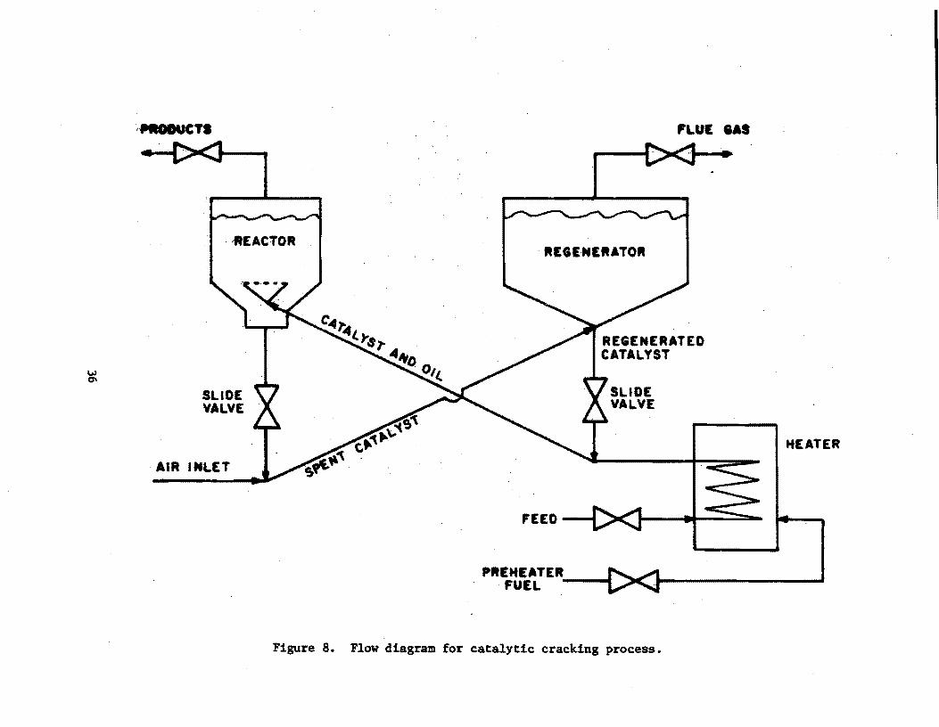
Catalytic cracking is a high-temperature, low-pressure process that converts certa!n heavier portions of crude oil into gases, gasoline blend stocks, and distillate fuels. A fluid catalytic cracking unit is composed of·two basic sections; reactor and. regenerator. The cracking reac,io~s take place continuously in the cracking section, with the spent catalYllt oeing continuously regenerated and returned to the reactoro Both the cracking and regeneration sections operate on the fluidization principle, which makes possible a continUOIlS flow of catalyst as well as hydrocarbon feed. Regeneration of the catalyst i~ necessary due to metal contamination and poisoning or deposits that coat the catalyst Rurfaces and thus reduce the area available for contact with the reactants. Figure 8 presents a flow diagram of the catalytic cracking process.
35
"'-l 0\
·,fJllt8lMlCTS
. ,REACTOR
SLIDE VALVE
. AIR IMLET
C"'1"",1.. ... r8.,.
.. EGE·MERATO ..
... ~() 0,1..
FEED
PREHEATER __ ...... . FUEL I
Figure 8. Flow diagram for catalytic cracking p-rocess.
FLUE lAS
HEATER
Pre-Startup Operations
Prior to startup, certain operations are performed to ready the FCC for service. These preliminary activities are necessary to help i~sure a smooth and orderly startup of the operating processes". Some of the pre-startup activities include;
1. General mechanical checkout of equipment. This includes pumps and other material handling equipment.
2.
3.
".Instrument System Review. This includes continuity ch~ckouts as well as l calibration of all trat)smitters, transducers and: control valves. :
l>ressuretesting of welds and a general washout of equip me pt. . with air,. nitrogen or water. "!'
I' I
4. Slow warmup of equipment .to dry .. ql,lt refractories and 'minimize the possibility of thermal shocks.
This curing o~ the refractories is done slowly and.<=:an take place over a number of days depending on the quantity of material involved.
Startup Operations
After .the refractories are dried out and conditioned, the next procedure is to load and circulate the catalyst. Once the catalyst is circulating, it is heated by means of an air heater. At this point, feed can be introduced to the FCC unit. The date of this introduction of feed to the FCC unit can be defined as the date of startup.
B. Fuel Gas Combustion Devices
Performance standards were promulgated for sulfur dioxide based on either a limit on hydrogen sulfide (not to exceed 230 mg/dscm or 0.10 gr/dscf) in the fuel gas or an equally effect.ive control of sulfur dioxide emissions. In addition, there is the requirement either for·continuous monitoring of sulfur dioxidein the gases discharged to the atmosphere from the combustion of fuel gases or for continuous monitoring and recording of the concentration of hydrogen sulfide in fuel gases burned in any fuel gas combustion device. Sources constructed, reconstructed or modified after June .11, 1973, are subject to the regulations.
Process Descriptiorl
A fuel gas combustlon device is defined as any piece of equipment, such as process heaters, boil'Crs and fiares used to combust fuel gas, but does' not include facilities in which gases are combusted to produce sulfur·or sulfuric acid. Flare combustion of process upset gas or fuel gas which is releas~d to the flare as a result of leakage from a relief valve is exempt. .
37

Pre-Startup Operations
As discus~ed previously, preparation of process equipment involves primarily a mechanical and instrument checkout.
Startup Operations
Startup of fuel gAR combustion devices is initiated with a test firing. Further information on procedures for startup of combustion devices can be found in the discussion of boiler startup (Subpart D) •.
C. Claus Sulfur Recovery Plants
Emissions of sulfur dioxide (S02) are limited to 0.025 percent by volume at 0 percent oxygen (dry basis) if emissions are controlled by an oxidation system or a reduction control system followed by incineration; or 0.030 percent by volume of reduced sulfur compounds and 0.0010 percent by volume of hydrogen sulfide (HzS) calculated as S02 at 0 percent oxygen (dry basis)' if emissions are controlled by a reduction control system not followed by incineration. Continuous monitoring and recording of S02 in the gases discharged to the atmosphere is required if an oxidation or reduction control system followed by incineration is used. Continuous monitoring and recording of H2S and reduced sulfur compounds in discharged gases is required if $ reduction control system not followed by incineration is used. Sources constructed, reconstructed or modified after October 4, 1976 are subject to the regulation.
Process Description
A Claus sulfur recovery plant is a process unit which recovers elemental sulfur· from hydrogen sulfide by a vapor-phase catalytic reaction of sulfur dioxide and hydrogen sulfide. A typical three-stage Claus unit designed to operate on a "standard" acid gas rich in hydrogen sulfide is shown in Figure 9.
Pre-Startup Operations
As discussed previously for the FCC process unit, preparation of process equipment involves the following activities:
1. general mechanical checkout (pumps, etc.)
2. instrument checkout
3. confirmation of "as-built" conditions with design specifications
4. pressure testing of welds
5. acidize compressor lines
6. general washout (air, nitrogen, or water):
7. commission utilities
38

\.oJ 1.0
ACID SAS
WATEII
HIGH PRESSUIlE STEAM
8011..1£11 FEED W"TEII
AlII 8LOWER
BOII.EII FEED WATER
SULF'ER PIT
Figure 9. Flow diagram for a typical three-stage claus sulfur recovery plant 3.
TAIl. GAS •

8. dry out refractories (slow warmup)
9. load catalyst
Startup Operations'
Startup for Claus sulfur recovery plants can be defined as the introduction ~f feed to the unit. Once feed is introduced, additional checks for leaks are performed. If no leaks are detected, process variables are aimed at test conditions previously determined.
40
REFERENCES
1. Personal communication wi~h Mr. Michael Volker, Ashland Oil Refining, Ashland, Kentucky. March 1, 't919.
2. "Chemical Process Industries" fourth edition, Shreve and Briak, McGrawHill Book Company, New York,1911.
3. Chute, Andrew E. Tailor Sulfur Plants to Unusual Conditions. Hydrocarbons Processing, April 1911, pp. 119-124.
41

Introduction
STORAGE VESSELS FOR PE,TROLEUM LIQUIDS - SUBPART K §60.ll0 - 60.113
The provisions of Subpart K of 40 CFR 60 dictate: ,perfor1T\anc'estandards for storage vessels for petroleum liquids. Subject to the requirements of Subpart K are storage vessels with capacities greater than 151 m3 (40,000 ,gal). but not exceeding 246 m3 (65,000 gal), which have commenced construction, reconstruction or modification after March 8, 1974. In addition, those storage vessels having a capacity greater than 246 m3 (65,000 gal) and having commenced construction, reconstruction or modif;ication after June 11, 1973, are subject to Subpart K. If the true vapor pressure of the petroleum liquid, as stored, is equal to or greater than 10.3 kPa (1.S psia) but not greater than 76.5 kPa (11.1 psia). the storage vessel must 'be equipped with a floating roof, a vapor recovery system or their equivalents. If the true vapor pressure is greater than 76.5 kPa (11.1 psia) , the storage vessel must be equipped with a vapor recovery system or its equtvalent.
The owner or operator of a storage vessel is required to maintain a file of each type of petroleum liquid stored. Reid vapor pressure, dates of storage and date on which the storage tank is emptied. In addition, the owner or operator shall record average monthly temperature and true vapor pressure. No performance testing is required for petroleum storage vessels.
Process Description
There are two types of petroleum storage tank emission reduction systems presently being used: floating roof and vapor recovery.
Floating roof storage tanks are used for storing volatile material with vapor pressure in the lower explosive ranges minimizing fires or explosive hazards. There are 'three types of floating roof tanks: pan, pontoon and double deck. The pan floating roof type has been used for the past 40 years and 1.8 now being phased out. Many operators have had tilting and sinking problems with this type of roof; besides, the pan roof also has a high vaporization loss around the periphery of the roof. The pontoon roof is mainly used on tanks with larger diameters and provides for better stability. Some pontoon roofs have a center drain with hinged or flexible connections for roof drainage problems. In addition, traps or dams are provided on the underside of the roof. The traps retain any vapors formed as a result of localized Rolar boiltng. The double deck floating roof, which is the most expensive, reduces the effect of solar boiling and has more rigidity than the pan and
42

pontoon floating roofs. Double deck roofs have compartmented dead-air spaces over the entire liquid surface. The roof also has drains for water accumulation and vapor traps on the underside of the roof.
A vapor recovery system is designed to handle vapors or1gmating from filling operations. The recovered vapors are compressed and charged to an absorption unit for recovery of condensable hydrocarbons. The system includes vapor lines interconnecting the vapor spaces of the tanks that the system serves. Each tank should be capable of being isolated from the system. Tank isolation and operation is by manual and pressure controlled butterfly-valves, regulators, and check valves. Knockout pots are normally us.ed at low points in the vapor line to remove condensate. N.oncondensable vapors are piped to a fuel gas ~ystem or to a smokeless flare. When absorption of the condensable vapors is not practical from an economic standpoint, these vapors, too, are either sent directly to a fuel system or incinerated in a smokeless flare.
Startup Operations
Since no performance testing is required for petroleum storage vessels, the 180 day test period does not apply in this case. However, the proper operation of either the floating roof and/or vapor recovery system is essential for the minimization of hydrocarbon emisaions. Storage vessel sys·tems are inspected and checked for structural, mechanical, electrical and hydraulic problems. The primary checks for the petroleum storage vessel are water pressure tests for structural defects and mechanical operation and clearances of the storage vessel's roof and seals, compressors and vapor control valves and actuators.
43

Introduction
SECONDARY LEAD SMELTING - SUBPART L §60.l20 - 60.123
'l'he .NSPS for this· category. is applicable to' the following facilities in secondary lead. smelters: pot furnac·es of. more than 250 kg (550 lb) charging capacity, .blast (cupola) furnaces, and reverberatory furnaces. Performance standards tor blast (cupola)' or reverberatory furnaces were promulgated for particulate. matter and opacity. Pa.rticulate matter cannot exceed 50 mg/dscm (0.022 gr/dscf). Opacity must be les.s than 20 percent. Performance standards for pot. f,urnaces were promulgated for opaci.ty only, which must be le.BB than 10 percent. Sources constructed, reconstructed or modified after June 11, 1973, are subject to the regulations.
Process Description
The processing of secondary lead centers around the utilization 'of three furnaces. Sme.lting operations on the scrap lead are carried out in the blast (cupola) .furnace and/or reverberatory furnace and the ·final purification steps in pot . ·furnaces.
The blast (cupola) furnace used in p~Qcessing secondary lead is similar to those in the ferrous industry; cylindrically shaped and standing vertically. Forced air, sometimes oxygen enriched, is introduced near the bottom of the furnace. The furnace is batch fed at the top. A typical charge is made up of about 80 percent scrap lead (generally battery plates and including 8 percent return slag) 8 percent coke, 2 percent iron, and 10 percent limestone. Heat is produced by the combustion of the coke which also provides an atmosphere for reducing the lead oxide feed. The lead metal collects at the bottom of the furnace and is customarily drawn off through a tap hole.
Reverberatory furnaces operate by radiating heat from the gas or oil fired burners and the surrounding hot refractory lining onto the contents of the furnace. The flame and products of combustion come in direct contact with the charge material. The furnace is commonly rectangular in shape with a shallow hearth and constructed of fire brick and refractory materials. The prinCipal use of the reverberatory furnace involves the melting and purification of lead by removal of extraneous ingredients.
The reverberatory furnace may be charged with molten lead from the cupola . a continuous basis. In this case, air is blown through the bath either ntinuously or intermittently to oxidize metal impurities. The metal dross,
Which is formed, floats on top of the lead and is removed intermittently by
44

!nagging. The lead product is tapped from the furnace into molds on an intermittent basis. If lead oxide drosses are charged to the furnace, a reducing agent such as granular carbon must be added to the bath to reduce the lead oxide to metallic lead. The furnace operates at a~out l2600C ' (23000 F) principally to allpw the reaction between metallic impurities and the oxygen sparged into the bath. The high temperature also allows for afterbumtna in the furnace proper. This is accomplished by Mintaining a ti, •• t furnac.e, that is, excessive air leakage into the furnace is prevented and ,the amount of oxygen introduced to the furnace is thus controlled. The reverberatory furnace product is a semi-soft lead which is more pure than that which the blast furnace produces. '
Pot furnaces $re used for remelting and for final 4lloyin. and refiniftl processes before pouring into product molds~" They are open-top, cer-..ic-lined kettles,.he!lispherically shaped and generally'raftle in aize frOll 0.9 to 45 metric ton (1 to SO ton) capacity. They are normally under-fired by natural gas burners. Refining is a batch operation that can vary frOll severa,l hours to two or mre days, depending on the required final composition. Drossina agents or alloys are generally added individ~lly and the bath .is no~lly agitated or, in some cases, air is bubbled through the bath., Drosses.re normally sktmmed off the surface of the lead by hand.
Particulate matter is'typically controlled by fabric filters in;see~ary le",d smelting operations.
Pre-startup Operations
Prior to startup, certain operations are undertaken to ready the furnace for production. T~ese prelfminary activities are concerned not only witb the operation of the furnace but also with the operation of material handling systems, and air pollution control systems.' '
For the furnace, some of the operations which are considered in tbe pre-startup category include:
1. Delivery, assembly and book-up of utilities
2. Installation of pollution control equipment
3. Installation of air handling system including stack
4. Cbeck out of wiring and control systems
5. Installation of refractory
These activities will typically require l,month to cOllplete.
Related to the operation of the furnace and crucial to achieving malei .. m production are the start-up of material handling,systems and t~e air pollution control systems. Problems in either of these ,two areas can cause delays of slwerRl months in preventing a smelting operation from acbieving design capacities. ,
45

In efforts to reduce worker exposures to lead, some new installations of secondary smelting may utilize completely enclosed, remote controlled operations. In these cases, debugging the new technology of remote control material hJ3.ndling may require several months •
. Startup Operations
'~e lead blast furnace (cupola) has a startup procedure similar to the b1.ast furnace used i~ the iron and steel industry. The startup procedure first requires the hand stacking of wood in the furnace. The time required for this operation will depend on the size of the furnace, however, it should not take more than a few hours. The next procedure which' takes 2-3 hr to accomplish, is the charging of the furnace with oil-soaked coke and upon completion the furnace is ready for ignition. Combustion air is introduced at the bottom of the furnace through tuyeres at a gauge pressure of 3.45 to 5.17 kPa (8-12 oz/ in2,) About 6-8 hr are allowed for the blast furnace to achieve operating temperature. Hard lead is charged into the cupola at less than full capacity' to provide molten metal to fill the crucible. Normal charges of slag, coke, iron and limestone are added to the furnace. As the level of molten metal rises, the slag is tapped off at intervals while the molten lead flows from the furnace at a more or less continuous rate. If the first few preliminary pours are successful, larger quantities of scrap lead will be charged until maximum capacity is achieved. Assuming no problems occur during initial startup operations, a facility can usually achieve its maximum prOduction rate in 4 to 7 days. The official startup date should begin when oil-soaked coke is ignited.
After pre-startup and heatup operations of a reverberatory "furnace, the material is slowly fed into the furnace to prevent thermal shock and to maintain a stable temperature while keeping a small mound of unmelted material on top of the bath. As the mound becomes molten, ore material is charged. The time required to reach maximum production is 3 to 5 days after material is first introduced into the furnace. The total time required from a cold start to maximum production will range from 4-6 days. The 180-day performance test period should begin when material is charged into the furnace. "
FollOWing pre-startup and heatup procedures, the charge is then slowly Introduced into the furnace developing a molten pool of lead. Since this is a batch operation, . the charging continues until the vessel is filled to rated capacity. TIle time required to achieve maximum production depends on the size of the furnace. Normally, maximum production can be reached in a few days. The official startup date should begin when the furnace is first charged t<llth lead.
46

REFERENCES
1. Personal communication with Mr. Hess, U.S. Smelting Furnace Company, Bellville, Illinois, March 9, 1979.
2. Personal communication with Hr. Borell, Gould Inc.., Industrial Battery Division, Sun Valley, California, MI;1rch 13, 1979.
3. Personal communcation with Mr. Pike, General Battery Corp., Reading, Pennsylvania, March 15, 1979.
4. Personal communication with Warrick Furnace, Chicago, Illinois, April 24, 1979.
5. Personal communication with Steve Meu1ler, AMAX Lead/Homestake, Buick Mine, Missouri, April. 10, 1979.
47

SECONDARY BRASS AND BRONZE INGOT PRODUCTION PLANTS - SUBPART M §60.l30 - 60.133
Introduction
The NSPS for this category applies to reverberatory and electric furnaces of 1,000 kg (2,205 lb) or .greater production capacity and blast (cupola) furnaces of 250 kg/hr (550 lb/hr) or greater production capacity. ·For reverberatory furnaces, the standard limits particulate discharge to 50 mg/dscm (0.022 gr(dscf) and opacity to less than 20 percent. Blast (cupola) or electric furnaces are governed only by an opacicy standard, which must be less than 10 percent. All facilities that commenced construction, were modified or reconstructed after June 11, 1973,. are subject to the regulations.
Process Description
Brass and bronze ingots are produced from three types of furnaces -reverberatory, rotary and crucible. In the industry, 95 percent are produced by direct oil or gas fired reverberatory furnaces. naces are also classified as reverberatory units for the purpose to the overwhelming predominance in the industry of these units, particulate emissions associated with electric furnace use, only furnaces are required to meet a mass particulate emission unit. presents a schematic of a typical ingot production facility •.
of the ingots. Rotary furof NSPS. Due and, the lower reverberatory Figure 10
Processing begins with ,raw materials which consist of copper bearing scrap including faucets, telephone or electric cable, radiators and brass turnings. Before blending in a furnace, the scrap is preprocessed to remove impurities and to concentrate like alloys. Pretreatment operations take on several forms. Mechanical methods include hand sorting of scrap into piles of like material, Htripping or shredding of wire covering or insulation, magnetizing of iron particleR to remove them, and briquetting for size reduction. Pyrometallurgical (heating) methods include sweating of scrap to remove low melting point metals, burning to remove wire insulation, drying in a rotary kiln to vaporize cutting fluids on machine shop scrap, and use of a blast furnace or cupola. Of these operationa, only the blast furnace (cupola) is governed by NSPS.
The blast furnace operation is a continuous process that accepts slag akimmiugR and other metal oxides which are byproduccs of the ingoc production furnaces. Coke, copper oxides and other materials are charged into the top of the furnace and combustion air, sometimes enriched with oxygen, is blown in through tuyeres at the bottom. The coke acts as both a fuel and a reducing agent through the production of carbon monoxide. The reducing
48
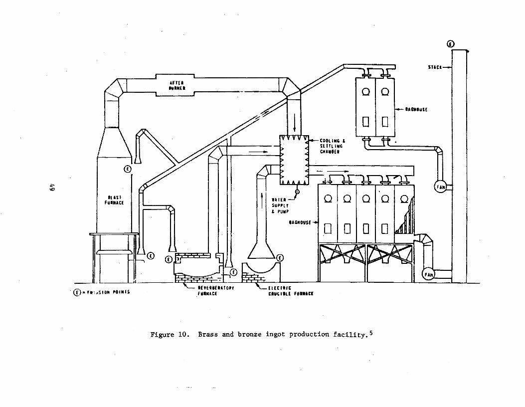
+:'
'" IU$I
FUIIACE
0:. f.I~SID" POlitiS
<D
Figure 10.
IAGMOVSf
UEeYl" eluelltE 'V .. AC(
Brass and bronze ingot production facility.S
<i)
snci
IU .. OIlSE

atmosphere allows direct reduction of metallic oxides and the resultant dense molten metal settles from the nonmetallic glass-like slag. The metal (black copper) is drawn off for further refining in the ingot production furnaces.
The reverberatory furnace is commonly rectangular in shape with a shallow hearth and constructed of fire brick and refractory materials. The furnace oper~~e8 by radiating heat from the gas or oil-fired burners and the surrounding hot refractory lining onto the contents of the furnace. The flame and products of combustion come in direct contact with the charge material. There are five distinct steps in producing brass or bronze of the desired specification in a furnace. First, the scrap materials are charged into the preheated furnace (charging) and, second, oil or gas is fired directly into the charge to melt the materials (melting). The charge is next brought to the desir.ed temperature and fluxes are added to remove impurities such as carbon, metal oxides, gases, etc. (refining or smelt~ng). Fourth, after the impurities are removed, metal is added to bring the alloy to the proper metallic composition (alloying). Finally, when analysis indicates the correct grade has been achieved and the melt is at the proper temperature, the metal is poured into ingots (pouring).
The electric crucible furnace follows a similar production sequence. Heat, however, is applied indirectly using high or low frequency induction heaters to raise the crucible temperature. The absence of direct flame contact on the metal minimizes metallic volatilization and thereby reduces patticulate generation.
Particulate emissions vary with the content of the alloy being produced and the presence of impurities in the scrap feed. MOst of the particu~ate emissions are metal oxides, predominantly zinc oxides (45 to 77 percent) and lead oxides (1 to 13 percent). Fabric filters are extensively used to control emissiqns from all three types of furnaces; although electrostatic precipitators have recently been adopted as well. .
For· various reasons, including the·promulgation of an NSPS for this industry, only one new plant has been constructed in the country since 1973. Total ingot production has remained relatively stable during this period,and producers have consolidated operations to the point where only 30 ingot manufacturers are now in operation. ' .
Pre-Startup Operations
There are numerous material handling subsystems in a secondary brass and bronze ingot production facility that must be individually tested before ineots are poured. The number and types of these systems is entirely dependent upon specific plant practice. Virtually all facilities will have a sorting/ classification process for the incoming scra~, a magnetizing station for removal of ferrous metals and a briquetting operation to facilitate furnace charging. These subsystems incorporate cranes, conveyors, pulleys, motors, hydraulic presses, etc., all of which must be operated'before startup~ Less common pretreatments such as wire stripping, shredding, sweating, burning and use of cupolas can be installed, although they are finding less favor in the
50

industry due to economic and environmental reasons and increased reliance on large scrap dealers who will clean and process raw scrap. Air pollution control devices, typically baghouses, must be operated to insure proper installation and structural integrity of all ductwork, housings and supports. Finally, the furnace(s) must be inspected for proper refractory installation (all units), freedom of rotation (rotary units, tilting reverberatory and electrical units) and correct charging clearances. Pretreatment (curing) of furnace refractory is crtional and left to the discretion of the plant operator. When practiced, curing typically takes 2 to 3 days. .Electric induction furnace equipment' (transformers, rectifiers, etc.) is also energized prior to startup. Complete checkout of this equipment necessarily requires actual plant startup. Plant construction typically takes 6-12 months, and individual pre-startup checks will be performed immediately after the specific piece of equipment is installed.
Startup Operations
Startup of a new or modified brass and bronze ingot production facility is the first day metal .is charged into the furnace and melting begins. Application of heat, either directly or indirectly, will cause generation of metallic fumes, which are the pollutant of concern. This startup date can be obtained by checking plant production records. Immediately prior to metal charging and light-off, the collection equipment is a~tivated to insure particulate emissions are controlled at all times. When baghouses are used, activation may also include injecting lime into the flue gas stream to neutralize acids and prolong bag life. As the operation of conventional design furnaces is straightforward, most operators will fully charge the unit with scrap and attempt to reach maximum production as soon as possible. Under these conditions mechanical and electrical problems will appear and be corrected immediately. Furnaces with new designs, although infrequently installed, will require a slower break-in period to insure all metallurgical conditions are correct and the furnace is operating as designed. Regardless of furnace type, industry contacts indicated that the l80-daytest time frame could be met by all plants. '
51
REFERENCES
1. Personal communication with Mr. Drickenmi1ler, American Brass Company, Dothan, Alabama. May 9, 1979.
2. Personal communication with Mr. Pinsof, Sipi Metals Corporation, Chicago, Illinois. May 10, 1979.
3. Personal communication with Mr. Stefinitis, I. Schumann Company, Bedford, Ohio. May 10, 1979.
4. Personal communication with Mr. Bowman, Brass and Bronze Ingot Institute, Chicago, Illinois. May 14, 1979.
5. Inspection Manual for Enforcement of New Source Performance Standards: Secondary Brass and Bronze Ingot Production Plants. EPA-340/1-77-003. January 1977.
52

Introduction
IRON AND STEEL PLANTS - SUBPART N §60.l40 - 60.144
The NSPS for Jron and steel plants applies to the basic oxygen process of steel production. The facility affected under this subpart is the basic oxygen process furnace (HOPF) which produces steel by refining a high carbon-content charge using a large volume of an oxygen-rich gas.
The mass emission standard promulgated under this subpart states that goses discharged from a BOPF shall not contain particulate matter in excess of 50 mg/dscm (0.022 gr/dscf). In addition, the exhaust gas from a control device sholl not exhibit an opacity of 10 percent or greater, except that an opacity of greater than 10 percent but less than 20 percent may occur ~ per steel production cycle. Facilities constructed, reconstructed or modified after June 11, 1973, are subject to the requirements of this subpart.
Process D~scrietlon
Steelmaking by a BOPF involves the melting, mixing and subsequent refining of scrap metal, molten iron, and fluxes charged to. the vessel by the injection of a high volume of an oxygen-rich gas. Oxygen may be top blown into the vessel by a water-cooled retractable lance or bottom blown through a set of fixed tuyeres. The former method' is the more common type of BOPF, whereas the latter is a recent process modification specific to the Quelle-Basic Oxygen Process (Q-BOP) furnace. A simplified flow diagram outlining steelmaking in a BOPF is presented in Figure 11.
The oxygen blow commences immediately following charging and continues for 8 predetermined length of time depending on the grade of steel desired and the charge composition. After the blow, the molten steel is checked to. determine if the endpoint chemical composition and proper tap temperature have been attained. If the desired temperature has not been reached, oxygen is reblown Into the hath until the proper temperature is reached. When the melt meets the required grade specifications, the furnace is tapped. Tapping involves rotating the vessel, pouring the finished steel into a teeming ladle. After tapping, the vessel is rotated back through the vertical and slag (the solid waste formed during refining) is poured from the furnace into pots located below the furnace floor. Following slagging, the furnace refractory lining and tap hole are checked for wear before another heat is started.
Typical air pollution control equipment installed'on BOP furnaces include 8 primary hood to collect emissions during the oxyge~ blow and possibly a secondary hood and furnace enclosure. to capture charging and tapping emissions.
53

V1 .,.
PARTICULATES WASTE GASES
SCRAP METAL --, MOLTEN IRON -~.-..I
AND t HEJ,T
"..;z ~
ALLOY ADDITIONS
t ... STEEL OXY'kN~E~CH - sAS --VESSEL ALLOYING .. - ....... ~ L ..r--"1
ADDITIONS .1: fl· <Ii .. SLAG
Figure 11. BOPF Steelmaking process flow diagram.

Collected fumes are normally vented to an electrostatic precipitator or high energy wet scrubber.
Pre-Startup Operations
Pre-startup operations of a BOPF include:
• conditioning of refractory lining and tap hole
• testing of mechanical controls
• instrument checks
• checking raw material, process gas and coating water distribution lines
The refractory lining, including the tap hole. must be preheated before the furnace is put in operation to prolong the life of the lining and to prevent sudden thermal stresses when the furnace is initially charged. The condit:1.oning period, which varies with furnace size and type of· refractory, typically lasts up to several weeks~
Instruments and mechanical equipment are checked to ensure proper operation and to correct any defects in installation. The usual time period required to check equipment varies from 1 to several weeks.
Start-up Operations
The start-up period (ranging from initial heat until attainment of maximum production) will vary in length from 2 days to a year, depending on the type of furnace, and production demands. Even though melt cycles will remain lengthy at first, each steel heat will be produced at the rated furnace capacity_
Once the furnace and ancillary equipment has been thoroughly checked out it will take approximately 8 hours to bring the vessel on-line. The cyclical nature of the process suggests startup should be defined as the time the furnace is put into operation for the first steel production cy~le.
55

REFERENCES
1. Personal communication with Mr. J. Galbreath, Whiting Corporation, Harvey, Illinois. 13 March 1979.
2. Personal communication with Mr. J. Hanley, Pullman-Swindell, Pittsburgh, Pennsylvania. 13 March 1979.
3. Personal communication with Mr. F. Schick, John Mohr and Sons, Chicago, Illinois. 13 March 1979.
4. Personal communication with Mr. B. Moore, Penn Engineering Corporation, New Castle, Pennsylvania. 13 March 1979.
5. Personal communication with Mr. Bonder, William B. Pollock Company, Youngstown, Ohio. 13 March 1979.
6. Personal communication with Mr. B. Wolf, Loftus Engineering Corporation, Pittsburgh, Pennsylvania. 13 March 1979.
56

Introduction
The standi that co.mbust Wl
produced by mUJ (2205 lbs) per a:lone are not j
and opacity is etructed or moe
Process Descri]
There are tion of practi{
Incinerat' combustion. T~
by mechanical I
successively il should be appl brought on lin, to prepare slu1
Two major mul tip Ie heart between these furnaces emplo
, of all~metal c for air pollut
The wet a principle that of liquid wate pollution is m peratures and Some particula used to contro
Introduction
IRON AND STEEL PLANTS - SUBPART N §60.l40 - 60.144
The NSPS for jron and steel plants applies to the basic oxygen steel production. The facility affected under this subpart is the I process furnace (BOPF) which produces steel by refining a high carb4 charge using a large volume of an oxygen-rich gas.
The mass emission standard promulgated under this subpart statl gases discharged from a BOPF shall not contain particulate matter il of 50 mg/dscm (0.022 gr/dscf). In addition, the exhaust gas from a device shall not exhibit an opacity of 10 percent or greater, excepl opacity of greater than 10 percent but less than 20 percent may oCC\ per steel production cycle. Facilities constructed, reconstructed 4
after June 11, 1973, are subject to the requirements of this subparl
Process D~scriptlon
Steelmaking by a BOPF involves the melting, mixing and subsequE of scrap metal, molten iron, and fluxes charged to the vessel by thE of a h:Lgh volume of an oxygen-rich gas. Oxygen may be top blown int vessel by a water-cooled retractable lance or bottom blown through·~ fixed tuyeres. The former method- is the more common type of BOPF. , the latter is a recent process modification specific to the Quelle-I Oxygen Process (Q-BOP) furnace. A simplified flow diagram outlinin, making in a BOPF is presented in Figure II.
The oxygen blow commences immediately following charging and c( for 6 predetermined length of time depending on the grade of steel c the charge composition. After the blow. the molten steel is checkec mine if the endpoint chemical composition and proper tap temperaturE attoined. If the desired temperature has not been reached, oxygen j
into the hath until the proper temperature is reached. When the me] the required grade specifications, the furnace is tapped. Tapping j
rotating the vessel. pouring the finished steel into a teeming ladlE tapping, the vessel is rotated back through the vertical and alag (t wnFJte formed during refining) is poured from the furnace into pots ] below the furnace floor. Following slagging, the furnace refractor~ and tap hole nre checked for wear before another heat is started.
TYllical air pollution control equipment installed' on BOP furnac a primary hood to collect emissions during the oxyge~ blow and possi secondary hood and furnace enclosure to capture charging and tappin~
53

\JI 00
:J --------• ,X MAUST
_ PIIETftUT.'MT f SLuDer. nlCIWPATIOII GAS Alit POLLUTION
I conlOIlAL' I COMTItOL
I • --------ILUHl ~-~ lSLUD." I
.. D'WATIIIW. . .'
lOllY SOLIDS TO lAIH' .... DISPOSAL
CO.IUITIOM
A •• ILOW'.
Figure 12. Sewage sludge incinerator process diagram.
TO ATMOSPH'.'
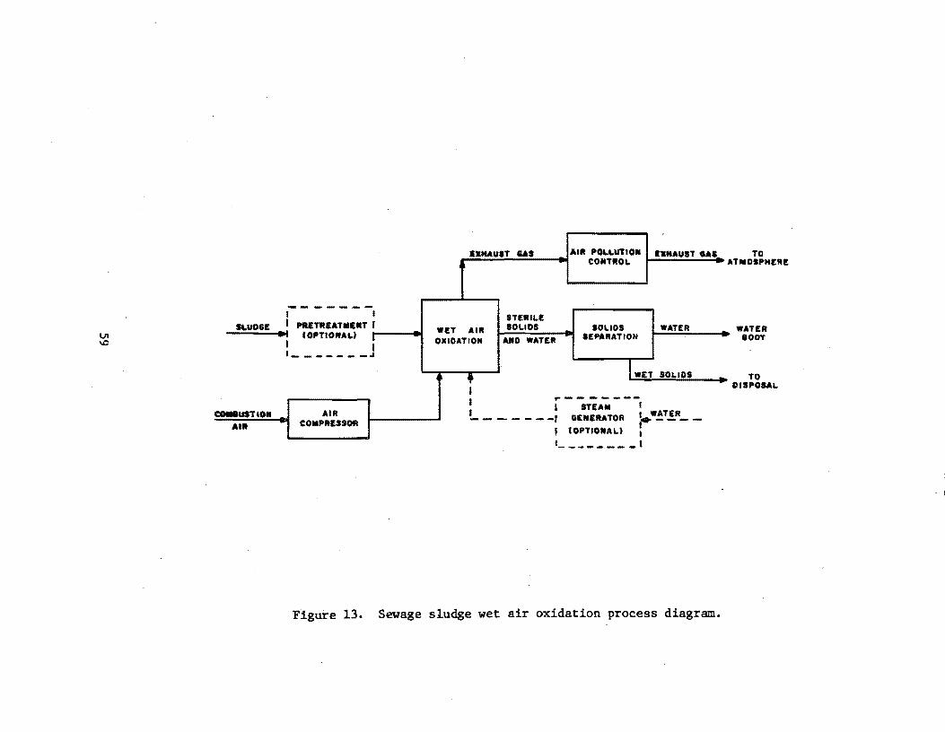
U1 \0
EXHAUST GAl AIR POLLUTION EXHAUST GAS CONTROL
-------I I STERILE
SLUDGE I PIIETREATIIII,NT J WET AIR 101.1 OS SOLIDS WATER ., (OPTIONAL) I OXIDATION HO WATER SEPARATION
I I 1 ______ -..1
, • IWET SOLtOS
I I '"I - -IT-EA";. - - -, I WATER ca.8USTIOil AIR ______ -J GENERATOR ~. ___ _
AIR COIIIIPRESSOR I tOPTIONAL) t - . I 1 _____ . ___ ,
Figure 13. Sewage sludge wet air oxidation process diagram.
TO ATIIOSPHE'"
WATER eOOT
TO DISPOSAL
~re-Startup Operations
1. Multiple Hearth: One to two weeks are typically allowed for instrumentation and mechanical equipment shakedown. This includes the operation of the combustion air source and the sludge feed system. Upon completion of this pre-startup procedure, the unit is heated to an operating temperature of about 927 0 C (17000 F). This must be done gradually in order to prevent stressing of the refractory material. Once at the operating temperature, the unit remains fired until it is thoroughly "dryed out." The heat-up and dry-out procedure consumes approximately one week.
2. Fluidized Bed: One to two weeks is required to perform an instrumentation and mechanical equipment shakedown similar to that for a multiple hearth furnace. Following this, the unit is heated up to its operating temperature of about 87loC (16000 F). This can be done relatively quickly since there is no refractory construction material. A typical heat-up period is three days. A drying-out procedure is not necessary.
3. Wet Air Oxidation: One to two weeks is required for instrumentation and mechanical equipment shakedown. The unit is operated by feeding water. only as part of the procedure. Since the unit operates at only 930 C (2000 F) to 204°C (4000 F), the heat-up period is only a matter of hours. Dry-out is not required.
Startup Operations
1. Multiple Hearth: After the pre-startup operations of heat-up and dry-out are completed, the unit is ready to receive sludge. The sludge mixture, which is mainly water, must be charged slowly at first to prevent thermal shocks and gradients within the refractory material. The unit must be run at partial capacity for approximately one week while the load is gradually increased. ,The day on which sludge is first introduced to the unit should officialiy be considered the startup date. Up until this point, including post heat-up, the unit could be shut down fc: mechanical or instrumentation failure, or more often, for a lack of sludge of proper consistency and quantity. For a mUltiple hearth furnace, the maximum pr'oduction rate can be attained one week from startup.
2. Flui~ized Bed: After the pre-startup operation of heat-up is complete, the unit is ready to receive sludge. The sludge is usually introduced at a rate within 20 percent of design capacity or greater. The day on which sludge is first introduced to the
60
unit should officially be considered the startup date. Since sludge is introduced at or near the design rate, there is no time elapsed between startup and the point when the maximum production rate is reached.
3. Wet Air Oxidation: After the pre-startup operation of heatup is complete, the unit is capable of receiving sludge at or near the maximum production rate. The day on which sludge is first introduced to the unit should officially be considered the startup date. Since sludge is introduced at or near the design rate, there is no time elapsed between startup and the point when the maximum production rate 1s reached.
61

REFERENCES
1. Process Design Manual for Sludge Treatment and Disposal, U.S. EPA Technology Transfer, October 1974. EPA-625/l-74-006.
2. Inspection Manual for the Enforcement of New Source Performance Standards -Sewage Sludge Incinerators, by Devitt and Ku1ujian, U.S. EPA, Research Triangle Park, N.C., February 1975.
3. Private Communication: Richard Shedlow of Nichols Engineering and Research Corporation, Belle Mead, New Jersey. t~rch 5, 1979.
4. Private Communication: Ed Sweeney of Dorr-Oliver Company, Stamford, Connecticut. -March 6, 1979.
5. Private Communication: Mike Mayer of Zimpro, Rothschild, Wisconsin. March 12, 1979.
62

Introduction
PRIMARY COPPER SMELTERS - SUBPART P §60.l60 - 60.168
The standards of performance for primary copper smelting affect the drying, roasting, smelting and copper converting facilities. Gases which contain particulate matter in excess of 50 mg/dscm (0.022 gr/dscf) from any dryer and sulfur dioxide in excess of 0.065 percent by volume from any roasters, smelting furnaces or copper converters cannot be discharged into the atmosphere. The standard for visible emissions limits opacity to 20 percent for dryers and facilities using 8 sulfuric acid plant to comply with the standards. Additionally, sources shall install and operate a continuous monitoring system for opacity and sulfur dioxide. Sources constructed, reconstructed or modified after October 16, 1974, are subject to these requirements.
Process Description
The copper bea·ring ores are either smelted as they corne from the mine or are subject to a preparatory process of grinding and floatation to transform low-percentage ores into high-percentage ores. Ore corning directly from the mine normally passes through a dryer to remove the moisture while grindingflotation processed ore is subsequently smelted down either directly or after partial roasting. Roasting removes part of the sulfur from the ore. There are two main types of roasters used in the industry: multiple hearth and fluidized bed. In the smelting furnace, iron oxide combines with siliceous flux to form a slag and leaving a material known as matte composed of copper, iron and sulfur. Two commonly used smelting furnaces are reverberatory and electric smelting. nle matte in the smelting furnace is reduced to copper in two stages of blowing with air in a unit called a converter. The first stage eliminates sulfur and forms an iron oxide slag by adding a siliceous flux. The slag is· then removed from the melt. In the second stage, the copper sulfide is reduced to metal; sulfur is eliminated as S02 leaving a material known as blister copper. The blister copper may be further refined to remove sulfur and oxygen,to be cast into anod-es for electrolytic refining. Figure 14 illustrates a combined flow sheet of a variety of choices in current and developing technology offered to smelter designers. The unit/processes chosen for startup evalatuion appear t~ be typical for the copper smelting industry in the United States.
63

1. I DRY~ -- '-.
,j .-.
2. ROASTER
• Multiple hearth
• Fluid Bed
~i.f ---3. SMELTING FURNACES
• Blast furnace
• Homada Blast furnace
• Reverberatory furnace
• Flash smelting
• Electric smelting
• Cyclone smelting ----------.,..-----.---4
matte
4. CONVERTER .- -_._----------1 • Pierce Smith
• Hoboken
• Top blown rotary
• ~tationary (; slag
BUster Copper to waste
REFINING FURNACE t_-----r Anodes
Figure 14. Flow diagram for copper smelting and various unit processes.
64
Pre-Startup Operations
Dryer: A rotary direct heat or indirect heat dryer is typically used in the industry. Four to seven days are allowed for dryer shakedown. During the shakedown period, a manufacturer's field engineer is on hand checking electrical, mechanical. hydraulic and combustion systems. Upon completion of prestartup checks, the unit will be turned over to the operator for startup or a manufacturer's application engineer is available for complex startups. Normally, startup is straight forward and an application engineer is not needed. Pre-startup operation should take no longer than 1 week.
Roaster:.
Multiple Hearth: Two to three weeks are allowed for pre-startup operations. If problems develop, an additional week is allowed. Curing and heatup of the furnace takes about 5-7 days. This operation must be done very slowly to prevent stress on refractory material. Total pre-startup consumes a 3-4 week period.
Fluidized Bed: Seven to nine days are required to perform the pre-startup operations. Following a successful pre-startup, the system is brought up to operating temperature (3-4 days); the system is now ready for process material. Total pre-startup operation may consume a 2-3 week period.
Smelting Furnace
Electric Smelting: Two to three weeks are required for pre-startup operations. According to manufacturers, this period of time is known as green tag. It also allows time for replacements of minor defective parts. As each subunit is installed, they are checked mechanically, electrically and hydrauli~ cally as needed. The electrodes and rigging, a major system for the furnace, is actuated to check alignment and operation. The electrical system is given special attention for grounds, insulation, de~d shorts, and high resistance. Secondary voltage is then applied to the transformer conductors at a very low current. Transformers are then energized with primary voltage (Power company electricity). Curing t.he furnace is usually accomplished by heating with electric energy or a supplementary fuel. At this time, the furnace is ready for charging.
Copper Converters: When a converter system is being installed, it requires the cooperation of many suppliers and contractors. Upon completion of sub-unit installation and checking, the unit is normally turned over to the owner. The period of time consumed during installation and checking is 3-6 months. During this time, all electrical, mechanical .and hydraulic systems are debugged. Other units and systems checked are: compressors, fuel lines, levelings, fans, pumps, gauges, refractory linings and the cooling, chemical feed and emergency systems. Two to three weeks are allowed to cure the refractory material of the converter. The final step in pre~startup operation is a dry run of the entire system to check out and coordinate the operation of individual units into a coherent system. A dry run normally takes 1 week. Heating the co'nverter to operating temperature requires 3 to 4 days. The total preliminary startup operation takes from 5 to 8 weeks.

Dryer: Startup of a dryer begins when ore is first fed into the dryer. If no problems develop, the dryer should achieve maximum production in l~ hours. Special procedures sometimes require the·presence of a manufaccurer's application engineer to make adjustments such as drum rotational speed, material fall slope, and temperature to attain the designed moisture content in the ore. No more than 2 days are required to make final adjustments. Manufa~turers indicated that the lBO-day period performance test period should begin when material is first fed to the dryer.
Multiple Hearth: After the pre-startup operations, the unit is slowly charged with ore to prevent thermal shocks and gradients within the refractory material. The load is gradually increased to maximum capacity consuming 1-2 weeks. The official startup should be when material is first introduced into the furnace. Prior to charging, the furnace could be shut down very easily for repair without major time expended.
Fluidized Bed: Following pre-startup operation and heatup, ore is slowly introduced into the furnace taking 2-4 days to reach maximum production. The official startup date should be when material is first introduced into the furnace.
Smelting Furnaces
Reverberatory Furnace: Following pre-startup and heat-up, ore is slowly introduced into the furnace developing matte. Matte is composed of copper, iron and some sulfur. Flux is then added to the matte to develop an iron oxide slag. In order to have a continuous process and to develop maximum production, a good matte is necessary. The development of a good matte, essential for maximum production, may take as long as 3 to 4 weeks and is dependent upon operator skills. Inexperienced operators may take as long as 2 months to develop a good matte. The official startup date should be when material is first introduced into the furnace.
Electric Furnace: After pre-startup operation and heat-up, the charge is slowly introduced into the furnace to develop a good matte and to prevent thermal gradients and shocks to the refractory material. During this period, flux is also added to develop a slag. Maximum production cannot be reached unless a good matte exists and this again may take 3-4 weeks depending on operator skills. The official startup date should be when ore is first introduced into the furnace.
Converter: After pre-startup operations and heat-up, the matte from the smelting furnace is introduced into the converter. If the first heat goes smoothly, the process may continue while slowly increasing the quantity of matte introduced into the converter until. maximum production is reached. It may take as long as 6 to 8 months to develop a maximum production rate. The official startup date should begin when material is first introduced into the converter.
6(;

REFERENCES
1. Personal communication with Mr. Hess, U.S. Smelting Furnace Co., Belleville, Illinois. March 1979.
2. Personal communication with Colorado Smelting and Mine, Denver, Colorado. March 15, 1979.
3. Personal communication with Treadwell Corp., New York, New York. March 13, 1979.
4. Personal communication with Pyro Industries, Mineola, New York. March. 13, 1979.
5. Personal communication with General Precision Systems, Glendale, California. March 1979.
6. Personal communication with Mr. Fluggie, ~evi Duty Heating Equipment, Watertown, Wisconson. March 9, 1979.
7. Personal communication with Mr. Galbreath, Whiting Corporation, Harvey, Illinois. March 9, 1979.
8. Personal communication with Mr. Bruecker, Surface Combustion, Toledo, Ohio. March 13, 1979.
9. Personal communication with the Copper Development Association, New York, New York. March 14, 19.79.
10. .Personal communication with Mr. Farkes and Mr. Nelson, Dwight Lloyd Research Laboratories, McDowell-Wellman Engineering Co., Cleveland, Ohio. March 14, 1979.
11. Personal communication with Mr. Nagite, Pennsylvania Engineering, Pittsburgh, Pennsylvania! March 14, 1979.
12. Personal communication with Mr. Douglas, Lectrome1t Corporation, Pittsburgh, Pennsylvania. March 9, 1979.
13. Personal communication with Mr. Kuzio, GE Raymond Bartlett Snow, New York, New York. March 16, 1979.
14. Personal communication with Mr. Persons, Lectrome1t Corporation, Pittsburgh, Pennsylvania. May 8, 1979.
67

15. Personal communication with Mr. Priestly, Door Oliver, Stamford, Connecticut. March 1979.
16. Personal communication with Mr. Defull, Colorado School of Mines Research Institute, Denver, Colorado. March 1979.
68

IntroductIon
PRIMARY ZINC SMELTERS - SUBPART Q §60.l70 - 60.176
Affected operations within this category are roasting (multiple hearth and fluid bed) and sintering. Particulates discharged into the atmosphere from a slntering machine are not to exceed 50 mg/dscm (0.022 gr/dscf) while sulfur dioxlde discharged from any roaster is not to exceed 0.065 percent by volume. A slntering machine which drives off more than 10 percent of the sulfur initially contained in the zinc sulfide ore concentrates is considered a roaster. Visible emissions are limited to 20 percent opacity from any sintering machine or from any affected facility that uses a sulfuric acid plant to comply wIth the standard. The owners or operators of a zinc smelter are required to install and operate a continuous monitoring system for opacity and sulfur dioxide. Sources constructed, reconstructed or modified after October 16, 1974, are subject to the regulations.
Process Uescription
Zinc ist:ypically found in ot:e called sphalerite containing impurities of lead, cadimum and trace elements. Sphalerite is normally processed at the mines to form concentrates containing up to 62 percent zinc and 32 percent sulfur. The smelting of zinc sulfide into oxide or metallic zinc is carried out by either a pyrometallurgical or a combined pyrometallurgical-electrolytic extraction process. The three primary steps of the pyrometallurgical extraction process are:
1. roasting (multiple hearth and fluid bed) of zinc sulfide concentrates .to reroove impurities and to form an impure zinc oxide called calcine.
2. sintering of the calcine to eliminate remaining sulfur, volatilization of lead and cadmium and formation of a dense permeable furnace feed, and
3. pyrometallurgical reduction of the zinc oxide to metallic zinc.
TIle smelting of zinc sulfide using electrolytic extraction requires two principal operations:
1. roasting, and
2. electrolytic extraction, after chemical leaching of calcine to produce 99.9 percent pure high grade zinc.
69

Figure 15 illustrates the pyrometallurgical and associated process units typically used in each step. NSPS limit emissions from roasting and sintering operations and therefore, a startup evaluation was not conducted for. the pyrometallurgical-electrolytic extraction process.
Pre-Startup Operations
Roasting-Multiple Hearth: Two to three weeks are allowed for pre-startup operations. If problems develop, an additional week is allowed. Curing the furnace and heat-up takes about 5-7 days. The off-gas stream temperature is about 7000 C (l,2920 F). The heat-up must be done very slowly to 'prevent stress on refractory material. The total pre-startup operation may consume a 3-4 week period.
Roasting-Fluid Bed: Seven to nine days are required for pre-startup operations. Three to four days are needed for the heat-up period. A fluid bed furnace does not have refractory material so the furnace does not need curing. The 'total time allowed for pre-startup is 2-3 weeks.
Sintering Machine: The installation and checkout of a sintering machine is a very complex operation involving many suppliers and contractors. This period of time is called construction and test-out and may require 3-4 months to complete. A major factor affecting the length of this period of time is the geographical location of the plant; isolated areas may make it difficult to obtain spare par,ts thus, delaying startup. The pre-:-startup operation is the most hazardous period during which component parts may be damaged. The test-out is done without load material. Some of the items checked are: instrumentation, structure, electric motors, mechanical clearances, conveyor belts, mixing drums, sinter breakers, and coolers. Curing the machine is a 5 to 7 day operation. Upon successful completion of the construction and test-out, the sintering machine is ready to receive material. The maximum
·time period for construction and test-out is 6 months.
Startup Operations
Roasting-Multiple Hearth: After pre-startup operations, ore is slowly introduced into the furnace in order to prevent thermal shocks and gradients in refractory material. The load is gradually increased to maximum capacity over a I to 2 week period. The startup date should be defined as the time material (ore) is first introduced into the furnace.
Roasting-Fluid Bed: Folloving the pre-startup and heat-up operations, the ore is slowly introduced into the bed, increasing to the maximum feed rate in 2-4 days. The official startup date should begin when material is first introduced into the bed.
70
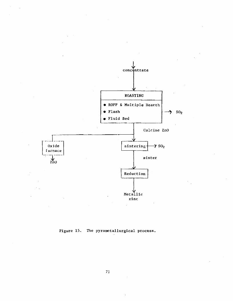
~ conc ntrate
ROASTING
• ROPP & Multiple Hearth
• Flash
• Fluid Bed
Metallic zinc
Calcine ZnO
sinter
Figure 15. The pyrometallurgical process.
71
Slntering Machine: After the pre-startup operation and heat-up is completed, the sintering machine normally goes into a ope shift per day operation for 2-3 weeks. This period allows the operators to become familiar with the equipment. Each daily startup takes about l~ hours to produce a product. Before going into maximum production, the machine will go into a 24 hr/day operation for about 2 weeks. By the end of the second week, operators and the machine should be ready for maximum production. However, the inexperienced operator will extend this time. On the average, the sintering machine and operator should be able to reach maximum production in 3-6 months. The time needed to reach maximum production for a sintering machine varies; new sinter machine designs and new processes require more attention than off-the-shelf sintering machines. The first year's production rate normally ranges between 70 to 80 percent because of malfunctions and repair time; however, the production rate usually increases in the succeeding year to a maximum production rate (90 to 100 percent). The official startup date should be designated as the day when material is first introduced into the machine. Manufacturers indicated that 180 days is a reasonable time period in which to reach maximum production for conducting performance testing.
72

REFERENCES
1. Personal communication with Mr. Williams, Dwight Lloyd Research Laboratories, McDowell-Wellman Engineering Co., Cleveland, Ohio. March 1979.
2. Personal communication with Pyro Industries, Mineola, New York. March 1979.
3. Personal communication with Mr. Bruecker, Surface Combustion, Toledo, Ohio. March 1979.
4. Personal communication with Mr. Nelson, Dwight Lloyd Research Laboratories, McDowell-Wellman Engineering Co., Cleveland, Ohio. March 1979.
5. Personal communication with Mr. Coulter, Dravo Corporation, Pittsbur~h, Pennsylvania. March 15, 1979.
6. Personal communication with Mr. Farkes, Dwight Lloyd'Research Laboratories, McDowell~Wellman Engineering Co., Cleveland, Ohio. March 14, 1979.
7. Personal communication with Mr. Latoweski, Kopper Company, Pittsburgh, Pennsylvania. March 15, 1979.
8. Personal communication with Mr'. Nell, the Bethlehem Corporation, New York, New York. March 14, 1979.
9. Personal communication with Mr. Smith, Mine and Smelter Supply, Denver, Colorado. March 1979.
10. Personal communication with Mr. Priestly, Door Oliver, Stamford, Connecticut. March 1979.
73

Introduction
PRIMARY LEAD SMELTERS - SUBPART R §60.l80 - 60.186
This NSPS category regulates the following facility operations for primary lead smelting: sintering machines, sintering machine discharge end, blast furnaces, dross reverberatory furnaces, electric smelting furnaces and con.verters. Particulate emissions from any blast furnace, dross reverberatory furRace or sintering machine discharge end are limited to 50 mg/dscm (0.022 gr/dscf). Sulfur dioxide is limited to 0.065 percent by volume from any sintering machine, electric smelting furnace, or converter. Opacity is limited to 20 percent from blast furnaces, dross reverberatory furnaces, sintering discharge end, or any facility that uses a sulfuric acid plant to comply with standards. Lead smelting facility owners and operators are required to install and operate continuous monitoring equipment for opacity and sulfur dioxide. Sources constructed, reconstructed or modified after October 16, 1974, are subject to the regulations.
Process Description
Lead is found in nature as a sulfide ore containing impurities of copper, zinc and other trace elements. At the mines, the lead ore is normally concentrated 'to 65-70 percent. Typically, the concentrate contains between 13-19 percent by weight of sulfur. The production of lead includes the following operations:
Sintering: Lead and sulfur are oxidized to produce lead oxide and to reduce the sulfur dioxide concentration to 85 percent. Simultaneously, the charge material composed of recycled sinter, sand and inert material is agglomerated to form a dense, permeable material called sinter. The sinter is then charged to a reduction unit such as a blast furnace.
Reduction: In the blast furnace, lead oxide is reduced to a molten lead bullion. The lead bullion then goes to the refinement steps.
Refinement: Impurities are removed from the lead bullion.
Figure 16 illustrates a flow diagram of a lead smelting process. Smelting manufacturers indicated that electric furnaces and converters are not used in the U.S. because of the high cost of energy; therefore, a startup evaluation 'as not conducted for these units.
74

--1- I SINTERING
... , 2. REDUCTION
Blast furnace
Dross Reverberatory
Electric Smelting
lead bu llion
1-- . ," 3. REFINEMENT
Converter
lead
'v
Figure 16. Lead smelting flow diagram with typical process units.
75

Pre-Startup Operations
Sintering Machine: The installation and checkout of a sintering machine is a very complex operation involving many'suppliers and contractors. This period of time is called construction and test-out; it may last 3-4 months. A major factor affecting the length of this period is the geographical location of the plant; isolated areas may make it difficult to obtain spare parts thus delaying startup. The pre-startup operation is the most hazardous period during which component parts may be damaged. The test-out is done without load material. Some of the items checked are: instrumentation, structure, electric motors, mechanical clearances, conveyor belts, mixing drums, sinter breakers, and coolers. Curing the w~chine is a 5-7 day operation. Inexperienced operators are a major problem in achieving a maximum production rate within a reasonable time frame. Upon successful completion of the construction and test-out, the sintering machi~e is ready to receive material. The maximum time period for construction and test-out is 6 months.
Reduction - Blast Furnace: The blast furnace for lead smelting is unlike that used in the Iron and Steel industry in that it has no refractory material, thereby eliminating the curing requirement. When a lead blast furnace is installed or reconditioned, each system is checked and reconditioned or replaced. A final checkout is then conducted coordinating the functions of all systems and units operating at rated capacity. This test period takes 2-3 hours. Some of the major systems/units examined are the water packet cooling system, flange corking, charging, weighing, fuel and all mechanical, electrical, and hydraulic systems in general. The furnace is now ready to receive a charge.
Reduction - Dross Reverberat'ory: Once the furnace is installed and all connection$ made, pre-startup operations begin. The pre-startup operaton takes 2-3 days. Simultaneously, the furn~ce is cured for 4-7 days depending on the size of the furnace. Finally, the furnace is, brought up to operating temperature and stabilized (2-3 days). The furnace is now ready to receive material. The total pre-startup operation consumes 5-7 days.
Reduction - Electric Furnace: Electric furnaces in the lead smelting ,industry are used for melting rather than smelting. The energy is too demanding for a smelting operation. Tw? to four weeks are allowed for pre-startup operations. Manufacturers call this period of time the green tag period (test-out). Individual, mechanical, electrical and hydraulic co~ponents are checked. Special attention is given to electrode rigging, electrical grounds, shorts and high resistance. Up,on successful completion of all checks, a low secondary voltage is applied to the transformer. If no problems develop, the primary voltage (Electric Company) energizes the entire system. Curing the furnace is either done with electrical or fossil fuel energy. Curing consumes a 3-4 day period and is normally done during the green tag period. The total pre-startup operations take about 1-2 weeks.
76
Startup Operations
Slntering Machine: After the pre-startup operation and heat-up is completed, the sintering machine normally goes into a one shift per day operation for 2 to 3 weeks. This period allows the operators to become familiar with the machine. Each daily startup takes about l~ hours to produce a product. Before going into maximum production, the machine will go into a 24 hr/day operation for about 2 weeks. By the end of the second week, operators and the machine should be ready for maximum production. On the average. the sintering machine should be able to reach maximum production in 3 to 6 months. The time needed to reach maximum production for a sintering machine varies, new sinter machine designs and new processes require more attention than off-the-shelf sintering machines. The first years production rate normally ranges between 70 to 80 percent because of malfunction and repair time; however, the production rate usually increases in the succeeding year to maximum production rate (90 to 100 percent). The officalstartup date should be when material is first introduced into the machine. Manufacturers indicated that the 180 day performance test period is a reasonable time in which to reach maximum production.
Reduction - Blast Furnaces: Following a 2-3 hour pre-startup, the furnace is ready to receive a charge and will normally reach a maximum production rate in 24 to 48 hours. The startup procedure for a lead blast furnace first requires the hand stacking of wood in the furnace. This operation takes 6-12 hours depending on the size of the furnace. Next, the blast furnace is charged with oil-soaked coke (3-5 hours). The blast furnace is ignited, brought up to operating temperatures and sinter is slowly fed into the furnace until the maximum charge rate is reached. During this time, other materials such as limestone, silica, litharge and slag-forming materials are added to the furnace to develop a high quality lead bullion pool for continuous operation. If the charge period goes smoothly, a blast furnace can reach maximum production in 24 hours; however, minor problems will extend this time to 2 days. The life of a blast furnace normally does not exceed 180 days, therefore, there should be no problems in testing this unit under maximum production conditions with'the specified time (180 days). The official startup should be designated as the time when the wood and coke are first ignited.
Reduction - Dross Reverberatory: After pre-startup and heat-up operations, lead bulH.on is slowly fed into the furnace to prevent thermal shQck and to maintain a stable temperature. The time required to reach maximum production is 3-5 days after material is first introduced into the furnace. The total time required from a ,cold start to maximum production will range from 5-7 days. The official startup date should be when material is first introduced into the furnace.
Reduction - Electrical FUrnace: Following pre-startup and heat-up, lead bullion is slowly introduced into the furnace. The transformer is then energized, heating the furnace and charge to desired temperatures; the introduction of more charge lowers the temperature and the furnace is energized again. This operation occurs many times until the furnace is filled to maximum capacity. The time required to reach maximum production is about 5 days from a cold start. Two to three days are considered heat-up time. The official startup date should begin When material is first introduced into the furnace.
77
REFERENCES
1. Personal communication with Mr. Williams, Dwight Lloyd Research Laboratories, McDowell-Wellman Engineering Co., Cleveland, Ohio. March 1919.
2. Peraonal ~ommunication with Mr. Schick, Mohr John and Son, Chicago, Illinois. March 1919.
3. Personal communication with Mr. Gallaway, Chicago Bridge and Iron, Chicago, Illinois. March 1919.
4. Personal communication with Mr. Gail, Ingal1 Iron Works, Birmingham, Alabama. MBrch 1919.
5. Personal communication with ColQrado Smelting and Mine,Denver, Colorado. March 1919.
6. Personal communication with Mr. Johnston, St. Joe Lead Co., Hercu1aneun, Missouri. March 29, 1919.
1. Personal communication with Mr. Boyd, the Bunker Hill Company, Kellogg, Idaho. March 29, 1919.
8. Personal communication with Rico Argentine Mining Co., Rico, Colorado., March 29, 1919.
9. Personal communication with Mr. Nelson, Dwight Lloyd Research Laboratories, McDowell-Wellman Engineering Co., Cleveland, Ohio. March 1919.
10. Personal communication with Mr. Coulter"Dravo Corporation, Pittsburgh, Pennsylvania. March 15, 1979.
11. Personal communication with Mr. Farkes, Dwight Lloyd Research Laboratories, McDowell-Wellman Engineering Co., Cleveland, Ohio. March 14, 1919.
12. Personal communication with Mr. Latoweski, Kopper Company, Pittsburgh, Pennsylvania. March 15, 1919.
13. Personal communication with Mr. JenSen, AMAX Lead Homestake, Buick Mines, fUasour 1. March 1919.
14. Personal communication with Mr. Douglas, Lectrome1t Corporation, Pittsburgh, Pennsylvania. March 9, 1919.
78

IS. Personal communication with Dr. Lyman and Dr. Cole, Lead Industrial Association, New York, New York. March 1979.
16. Personal communication with Mr. Priestly, Door Oliver, Stamfo!d, Connecticut. March 1979.
79

Introduction
PRIMARY ALUMINUM REDUCTION PLANTS -SUBPART S §60.l90 - 60.195
(Amendments to the NSPS for this category will be promulgated shortly; the requirements detailed here incorporate these amendments.)
The NSPS for this category applies to potroom groups and anode bake plants, regardless of size, which are located at primary aluminum reduction plants. Performan~e tests are required at least once each month during the life of the affected facility, but the owner or operator may petition the EPA administrator to establish an alternative requiring less frequent testing' for a primary control system or an anode bake plant.
Performance standards have been established for fluorides and opacity. Fluoride emissions are limited to: (1) 1.0 kg/Mg (2.0 lb/ton) of aluminum produced for potroom groups at Soderberg plants; (2) 0.95 kg/Mg (1.9 lb/ton) of aluminum produced for potroom groups at prebake plants; and (3) 0.05 kg/Mg CO.l 1b/ton) of aluminum equivalent for anode bake plants. Potroom emissions could exceed the applicable Soderberg or prebake plant standard, but could never exceed 1.30 kg/Mg (2.6 lb/ton) , if an owner or op~rator could establish that the emission control system was prop~rly operated and maintained at the time the excursion above the standard occurred. Opacity must be less than 10 percent for potroom groups and less than 20 percent for anode bake plants. Sources constructed, modified, or reconstructed after October 23, 1974 are subject to the regulations.
Process Description
All aluminum produced in the United States is by electrolytic reductiori of alumina (A1203)' Alumina is itself a product produced from Bauxite ore. Figure 17 presents a flow diagram of the aluminum reduction process. The process is carried out in shallow rectangular cells (Pots) constructed of carbon coated steel shells (cathodes) utilizing consumable carbon blocks (anodes) which are suspended above and extend down into the pot. A series of these cells, when connected to a common electrical supply, is considered a potline. Potlines are normally constructed as two adjacent buildings approximately 1,200 ft long.
Cryolite, a double fluoride salt of sodium and aluminum (Na3AlFs), serves as both an electrolyte and a solvent for alumina. The resistance of the cells causes them to be heated and operate between 9500 and 9800 C (1,7400 to 1,8300 F). During the reduction process, aluminum ions are reduced to aluminum. The oxygen released reacts with the anode to form carbon dioxide and carbon monoxide. Molten aluminum is periodically tapped from beneath the cryolite bath and moved to holding furnaces prior to being cast into ingots.
PO

Three different types of cells are used for the production of aluminum: the vertical stud Soderberg (VSS), the horizontal stud Soderberg (HSS), and the prebake (PB). These cells differ in the design for introducing the electrical current to the cryolite bath. Soderberg cells utilize a consumable anode which is baked in situ. A mixture of ground petroleum coke and coal tar pitch is 'periodically added to the top of the anode to renew it. Heat from the process bakes the lower boiling organics and fuses the new material to the old anode. This system precludes the need for a separate anode baking facility.
The PB cell uses an anode that is prebaked. Since the anode is consumed during normal operation, the old anode remnants (butts) are replaced periodically with new anodes. These butts are cleaned, ground, mixed with new coke and blended together with coal tar pitch in an anode plant. The mixture is weighed, formed into bricks, then slowly baked in a furnace. This pr9cess cycle can take up to 60 days.
Fluoride emissions ftom these processes are controlled by several methods: dry scrubbers (baghouses), venturi scrubbers, wet electrostatic precipitation, or impingement devices. Dry scrubbers are the most common, and all utilize cell grade alumina to adsorb the gaseous fluoride. This alumina is then used in the pots for electrolytic reduction. Various methods such as coated bags, alumina injection, and fluidized bed dry scrubbing, are employed to provide fluoride/alumina contact.
Pre-Startup Operations
In a prebaked operation, the anode plant is necessarily constructed and put into operation 2 to 6 months before aluminum is produced in the potline operation. This insures that a sufficient supply of anodes is available for production. Anode production involves crushing, shaking, screening, classifying, mixing, pressing, and baking of the ~aw materials. Each of these mechanical systems is checked without load prior to startup. These tests are made after each system is operational and collectively will take 2 to 3 months. When the anode plant includes a baking furnace, it must be conditioned by curing the refractory for 2 to 3 'weeks on a low fire before the first green anodes are baked.
Major components of an aluminum reduction plant include materials handling equipment (cranes, conveyors, pumps), electrical equipment (rectifiers, transformers, busbars), steel-shell pots and associated anode support structure, and the air pollution control equipment. These systems are all individually checked before plant startup to insure they are operational. However,all systems, especially the electrical and control equipment, require a load to insure they meet design specifications.,
The green cathode is "balted-out" by placing resistor coke in the pot and setting the anode on this coke. Current applied through the anode serves to heat, dry, and bake the green cathode lining. This operation takes two days per pot, and is the initial step of startup.
82

C/:) i-'
COIl ,... PITCH
EL.ECTRICITY
ALUIlINA (.AI2 0 3 1
~
CVlTER -WORKED OR
SIOE-WCftED. P"EBAKE
EL.ECTROLYTIC CELL,
Oil
ELECTROLYTES: CRYOLITE
(No3 AIF, ' FLUORSPAR (CoFZ)1
AND AIF3 I UNLOADING a I STORAGE
r HORllONTAL
OR VEIITICAL
SODERBERG EL.ECTaQI.'I'TIC REDUCTION
CELL
LIQUID MTCH
STEAII
ELECTRICITY
CAST ALUMINUM TO
SHIPPING
PASTE
Figure 17. Process flow diagram for primary aluminum reduction. S

Startup Operations
Prebake plants (considered likely to be the most widely used type in the future) require that pots be started sequentially, such that startup of a potline is considered to be the day the first pot produces aluminum at its designed capability. A preliminary step in potline startup (those equipped with dry scrubbing/baghouse systems) is the activation of the primary air pollution control system, including alumina movement through the system. This ensures that fluoride emissions from all pots are controlled as they come on line. DeBign flow rates and temperatures, however, are not reached until all pots are in service. The individual pots are placed on line, one at a time, with a maximum of three or more pots started per day_ Some plants may elect to introduce up to 20 pota at one time. In these cases, the pots are operated for 1 week before additional pots are energized. For typical potline sizes of 100 to 180 pots, the entire startup procedure may last from 150 to 300 days. In light of the fact that this time frame may exceed the l80-day testing requirement, enforcement proceedings may be required to establish performance testing schedules at .individual plants. Greenfield (new potline in a new location) pot startup is accomplished by adding powdered cryolite to a pot and slowly heating it to 9700 C (1,7800 F). During this time, the anode-cathode distance is opened, the electrical equipment is monitored for short-circuits and the pots are continually inspected to insure against breakdown of the cathode lining and anode overheating. This phase is critical as a poorly adjusted anode can quickly overheat and destroy the cathode lining. Since the pots are connected in series, an electrical failure will trip the entire potline. Initiation of metal tapping takes from 7 to 10 days after alumina is added, as a stable molten aluminum pad must be established in every pot. Testing would be required within 60 days of the last pot being put into ~ervice.
Startup of an anode bake plant is considered to be the first .baking of green anodes. Fluoride emissions from this operation will commence (a) with this first bake, if the anode plant is an expansion of an existing facility and butts, containing fluoride, are recycled, or (b) with the initial recycling of butts in a greenfield operation •
. Soderberg plants, which are not likely to be chosen for new sources in the years to come, may require from 180 to 360 days to meet maximum potline production, as the physics of in-situ anode production is complex and there is greater potential for problems. Since the anodes are baked in-situ, the entire anode production process must be de-bugged before aluminum production can begin. The initial anode for.each pot must be mixed, incorporated into a support system, connected electrically and then baked before alumina is added. An attempt at production can be made once the individual anode is ready. Should an anode problem occur the entire support assembly must be disassembled, and a new anode mixed, reassembled and baked before another attempt is made. As this time consuming procedure may occur at each pot, the ability of an entire potline to meet maximum production may be delayed, requiring enforcement proceedings to estabHsh performance testing schedules.
83

REFERENCES
1. Personal communication with Mr. Alberts, Noranda Corporation, New Madrid, Missouri. March 29, 1979.
2. Personal communication with Mr. Howarth, Alumex Corporation, Buc Keystown, Maryland. March 29, 1979.
3. Personal communication with Mr. Jansen, Eastalco Corporation, Frederick, Marylarid. March 30, 1979.
4. Personal communication with Mr. Yeager, Anaconda Aluminum Corporation, Louisville, Kentucky. April 23, 1979.
5. Technical Guidance for Control of Industrial Process Fugitive Particulate Emissions. 1977. U.S. Environmental Protection Agency, EPA-450/3-77-0l0.
84

WET PROCESS - PHOSPHORIC ACID PLANTS - SUBPART T §60.200 - 60.204
Introduction
For the purposes of this regulation, wet process phosphoric acid plants are defined as any facilities manufacturing phosphoric acid by reacting phosphate rock and acid. Affected facilities include any combination of reactors, filters, evaporators, and hotwells. Emissions of total fluorides are limited to 10 g/metric ton (0.02 lb/ton) of equivalent P20S feed. Equivalent P20S feed is defined as the quantity of phosphorous, expressed as phosphorous pentoxide, fed to the process. Sources constructed, reconstructed, or modified after October 22, 1974, are subject to the regulation.
Process Description
The sulfuric acid or wet process produces phosphoric acid by the reaction of phosphate rock with sulfuric acid which also results in the precipitation of calcium sulfate (gypsum). Figure 18 is a simplified flow diagram of the process. Phosphate rock is ground in a special ball mill with dilute phosphoric acid (recycled) and the resultant slurry mixture is then passed into multiple reactor and digesting tanks for reaction with sulfuric acid. Cooling is required to remove the heat of reaction. Water vapor and gaseous impurities are carried to an absorber where fluosilicic acid is recovered. Acid digestion of the slurry requires 4 to 8 hours at temperatures of about 750C (1670F). Violent agitation and close temperature control are required for the production of uniform, easily washed and filtered gypsum (CaS04 • 2H20) crystals. Without this close control, the anhydrite would form, become subsequently hydrated, and result in plugging of pipes.
Slurry from the digester tanks passes into horizontal, rotating, tiltingpan-type vacuum filters where phosphoric acid (30 to 35 percent P20S) is removed from the filter cake. This acid filtrate is then concentrated to 54 percent P20S by evaporation.
Pre-Startup Operations
Mechanical checkout is begun as soon as specific units or groups of interrelated units are reported as mechanically complete by the construction contractor. These checks include:
• alignment of all motor driven equipment
• hydrostatic testing of all liquid handling equipment
85

().) 0\
PHOSPHATE ROCK (CALCINED)
MILL
WATER r--~"".Asa
VACUUM FLASH COOLER
SULFURIC ACID
REACTOR
FLUORINE SCRUBI
WEAK PHOSPHORIC ACID RECVCLE
FLUOSILIC IC ...-------... ACID TO RECOVERY
WASH WATER
SLURRY
FILTRATE RECEIVERS
PHOSPHORIC ACID (10-35" P2 0,'
TO 'VPSUM POND
VACUUM EVAPORATOR
PHOSPHORIC AC~D (54" P20,'
Figure 18. Flow diagram of the wet-process phosphoric acid production process.

initial checkout of all instrumentation loops, with physical or electronic calibration where possible
integrity check of all electrical circuits and proper rotation of electrically driven units
e proper performance of vacuum generating equipment and vacuum handling equipment such as flash coolers and filtration units.
These steps would be carried out by both maintenance and mechanical engineering personnel and would take at least 1 week. Any significant design faulte or failures could appreciably alter this time period.
Once mechanical acceptance has been completed, process evaluation is begun by operating all units "on water" to check for leaks and to evaluate pump capacities and instrument calibration.
Startup Operations
Once the system has been operated on water for.a long enough time to insure equipment integrity and the ability of driven equipment to perform within design limits, staged operation can be initated. Startup is best defined as the point when phosphate rock and sulfuric acid are first added to the reaction vessel. The normal feed ratio is about 726 Kg (0.8 tons) of 100 percent sulfuric acid per 907 kg (ton) of rock and varies depending on the quality of rock. These two raw materials are added at low rates initially, until the slurry in the reaction tank is of proper concentration and consistency. Under normal circumstances, this initial charging of the·reactoJ; can take 8 to 16 hours while the proper concentration is usually achieved in 16 to 48 hours. The plant is then operated at continuous flow conditions but only at half capacity. As confidence in and knowledge of equipment and process is gained, rates are increased to design levels. This can involve 1 to 3 weeks in the absence of unusual circumstances. Once design capacity is achieved, the plant initiates a 5 to 7 day test period, during which time all operational, mechanical, and chemical parameters must be measured to insure that all equipment operates within design conditions and that all guaranteed process rates, efficiencies. and recoveries are met. Upon completion of a successful test period, the plant is legally accepted (possibly with provisions to upgrade equipment if necessary).
87
REFERENCES
1. Personal communication with Mr. G. M. Hebbard, New Wales Chemicals, Inc., Mulberry, Florida, March 23 and March 27, 1979.
2. Personal communication with Mr. Alan Martin, W. R. Grace and Company, Bartow, Florida, April 6, 1979.
3. Personal communication with Mr. Robert Schmidt, Gardinier, Inc., Tampa, Florida, April 18, 1979.
4. Personal communication with Mr. James C. Daniel, U.S.S. Agrichem/Divisiori U.S.S. Steel, Fort Meade, Florida, May 18, 1979.
88
SUPERPHOSPHORIC ACID PLANTS - SUBPART U §60.2l0 - 60.214
Introduction
Superphosphoric acid plants regulated under this part are defined as any facility which concentrates wet-process phosphoric acid to 66 percent or greater phosphorous pentoxide (P20S) content by weight for eventual consumption as a fertilizer. Affected facilities include any combination of evaporators, hotwells, acid sumps, and cooling tanks. Total fluoride emissions are limited to 5 g per metric ton (0.01 lb/ton) of equivalent P20S feed, defined as the quantity of phosphorous pentoxide fed to the process. Sources constructed, reconstructed or modified after October 22, 1974, are subject to the regulation.
Process Description
Superphosphoric acid is produced by concentrating 54 percent PzOs phosphoric acid to about 70 percent (± 2 percent) PzOS' Two commercial processes used to accomplish this are vacuum evaporation and submerged combustion, although the latter process is virtually outdated. In the vacuum evaporation process, depicted in Figure 19, clarified 54 percent PzOS acid is continuously fed to a vacuum evaporator from which hot gases containing water vapor and fluorides are condensed in the water-cooled barometric condenser. Condenser water flows to the hotwell prior to draining to the gypsum pond. Concentrated acid is drawn from the evaporator to cooling tanks and then to storage.
In the submerged combustion process, Figure 20, hot gases are forced below the surface of the 54 percent P20S phosphoric acid in a submerged combustion evaporator. Water vapor, fluorides, and acid mist are driven from solution and concentrated acid is drawn off as product.
Pre-Startup Operations
The major piece of equipment requiring a thorough mechanical checkout is the evaporator. In the past, falling-film evaporators have been used but have b~en replaced more recently with forced-circulation units. A disadvantage of the falling-film type was the inability to uniformly distribute the liquid a8 a film inside the exchanger tubes.
The evaporator is typically a shell and tube exchanger with high pressure steam input, a high-volume, low-head, recirculation pump, and is operated at about 6.75 to 20.3 kPa (2 to 6 in. Hg) absolute pressure. Initial checking of the evaporator assembly is carried out by the contractor while the plant will
89

-.0 o
WATtR
- 1 , eAROMETRlC
VACUUM CONDDtS£R
EVAPORATOR I~ '" STEAM i'"
. ,;
54% P205 ... SCRUB8E:R .... ,. ACID
I~
\ J
- - ,~ HOTWELL
" PRODUCT COOLER
I ....
Figure 19. Superphosphoric acid production by the vacuum evaporation process.
TO ATMOSPHERE
;~
SEPARATOR
'V GYPSUM
POND
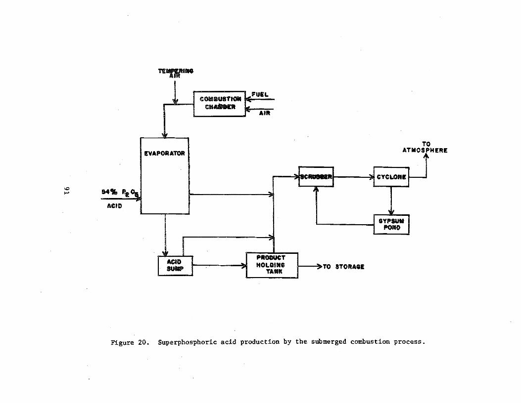
\0 ~
Tfl'Dl"-
! COMBUST" ... 'UEL r-
CH&In8n ~ I""" AIR
'I;'
AT EVAPORATOR J
... CYCLOIII I--r
14., p.t~ ... ~ , ... ACID
'Ii GYPSUM
POfOO --"" ..
,~ PRODUCT
ACID ... HOLDING ~ TO STORAGE sua. ,. TAM"
Figure 20. Superphosphoric acid production by the submerged combustion process.
o HERE

perform their own debugging procedures when the equipment is delivered. The plant would check the circulation pump for alignment, rotation, and with couplings disengaged, and also check bearings and packing. All acid-handling equipment is filled with fresh water for about 2 hours during which time leaks are detected and pumps, ammeters, flow meters, etc. are checked for capacity and calibration. A plant engineer will also inspect the equipment for proper welds and to verify the construction material (usually Hastelloy G - 20 to 30 percent nickel). Operating vacuum is then pulled on the system and held for at least 8 hours to check for vacuum leaks. Steam lines are then blown out to remove mill scale, welding rods, or other extraneous materials. Water and steam are then introduced to the plant and the water is evaporated for 5 to 6 hours to check pumps, instrument loops, control valves, and other pertinent components.
Startup Operations
Upon completion of the process equipment checks, the system is recharged with acid and the acid feed is ini~iated; this can be considered as plant startup. For normal circumstances involving no equipment failures or innovative designs requiring additional process evaluations, the preliminary equipment checks consume about 2 weeks and the maximum design rate can be achieved in about 48 hours. Approximately 2 to 3 weeks after the startup period, a performance run of about 3 days will begin, during which time all phases of operationrnust be as specified including emission rates and plant efficiency expressed as unit weight of product per unit weight of steam input. Under normal conditions, 180 days is adequate time for conductance of source tests·,
92
REFERENCES
1. Personal communication with Mr. Jack Smith, J. R. Simplot Co., Pocatello, Idaho, May 15, 1979.
2. Personal communication with Mr. C. G. 'Meier, Farmland Industries, Bartow, Florida, May 15, 1979.
3. Personal communication with Mr. Larry Hinderager, J. R. Simplot Co., Pocatello, Idaho, May 18, 1979.
4. Personal communication with Mr. Joseph G. Peters, New Wales Chemicals, Inc., Mulberry, Florida, May 29, 1979.
5. Personal communication with Mr. Thomas Faulkner, Swenson Evaporators! Division of Whiting Corporation, Harvey, Illinois, May 30, 1979.
6. Background Information for Standards of Performance: Phosphate Fertilizer Industry EPA-450!2-74-0l9a, October 1974.
93

Introduction'
DIAMMONIUM PHOSPHATE PLANTS - SUBPART V §60.220 - 60.224
Granular diammonium phosphate plants regulated in this part are defined as any plant manufacturing granular diarnmonium phosphate by reacting phosphoric acid with ammonia. Affected facilities within each plant include any combination of reactors, granulators, dryers, coolers, screens, and mills. Emissions of total fluorides are limited to 30 g/rnetric ton (0.06 lb/ton) of equivalent P20S feed (the quantity of phosphorous, expressed as phosphorous pentoxide, fed to the process). Sources constructed, reconstructed or modified after October 22, 1974, are subject to the regulation.
Process Description
Two possible methods exist for the manufacture of diammonium phosphate (DAP); one results in run-of-pile product (large pellets), made in a TVA cone mixer, which cures in a storage pile and is then granulated; the other results in a slurry which is granulated in an ammoniator or granulator. Since the latter (slurry) process is the most likely to be employed in new facilities, the following process description, flow diagram, and startup operations will apply to this type.
The production of DAP (high-analysis fertilizer) results in different compositions depending on the type of phosphoric acid used in the process. If phosphoric acid made by burning elemental phosphorous in an electric furnace is used, the resulting fertilizer composition is 21-54-0 (21 percent total nitrogen, 54 percent available phosphate as phosphorous pentoxide, and 0 percent soluble potash as K20). If wet-process phosphoric acid is used, the resulting analysis is l8~46-0. A flow diagram of a typical plant is illustrated in Figure 21.
Vapor or liquid anhydrous ammonia and phosphoric acid are proportioned to an agitated atmospheric tank (preneutralizer) to maint.:lin a ratio of 1.3:1.5 moles of ammonia per mole of phosphoric acid. The exothermic reaction that takes place results in the evaporation of approximately one tenth of the product as water. The slurry obtained from the preneutralizer flows into the amrnoniator-granulator at about 121°C (2500 F). As it is distributed over the bed of solid material, it reacts with additional ammonia fed through a distributor pipe beneath the bed to complete the reaction to a mole ratio of 2.0 (diammonium phosphate). Material from finished product screening is recycled to the ammoniator along with additional solid raw materials to aid in moisture control. The moist granules exiting the arnrnoniator proceed through an oil-or gas-fired concurrent rotary dryer where moisture content is lowered to about
94

\0 \Jl
.... .-.c MID ( tl" Po
AIQtOIIIU" ".nATE,,,,, YO oT.l IOLIDS ,
""ENEUTRALIZER
..... O.UATOIt
AIR
Fun
OIlYE,.
luCIIET ELEVATOR
Figure 21. Process flow diagram for diammonium phosphate production4.

1 percent. Dry product is then cooled by a countercurrent flow of air in a rotary cooler and screened with coarse material being returned to the ammoniator. In some plants ,. hot screening is employed such that cooling is achieved prior to storage and shipping. Exhaust gases from the dryer (and cooler) pass through cyclones or wet scrubbers for particulate removal while effluent from the ammoniator are usually scrubbed with incoming phosphoric acid prior to discharge to the atmosphere.
Pre-Startup Operations.
As depicted in Figure 21, the process consists of a wet end (prior to ammoniator) and a dry end (ammoniator and downstream). All equipment on the wet end is water-batched to check for leaks and proper valve operation. All pumps, electrical connections, and instrumentation are thoroughly cheeked and evaluated with respect to proper operation and calibration.
The granulator, dryer, and cooler (if used) are all inclined slightly and must be mechanically checked for proper rotation and tracking. The gear box and driving mechanism must mesh properly and operate without excess noise or heat. This can take from 2 hours to 2 weeks.
The dryer furnace would undergo preliminary operations similar to those described previously for fossil fuel boilers.
Once all equipment is installed and verified for proper installation, connections and mechanical operation, the plant is operated dry with recycle material (rather than slurry) to check conveyors (recycle, belt, and elevator) for binding prior to initial charging. All other equipment is also run dry prior to initial charging.
Startup Operations
Once all process equipment has been operated with dry recycle material and has been shown to operate reliably, the preneutralizer (or reactor) is charged with ammonia. water, and phosphoric acid and the process is begun. Initial charging varies depending on the size of the plant but usually would require 45-91 metric tons (50-100 tons) of DAP.
The key, controlling factor with respect to proper operation of the entire plant is the particle size of the finished material. Fines are recycled to the granulator while oversize material is recycled to the mills and back. to the granulator. Recycling is important to the process and too much on-size material can also be a problem. Normal recycle to product ratio is 3:1. Throughout the life of the plant, the operators are constantly trying to find the one limiting piece of equipment which could affect the entire facility's capability.
Startup is best defined as the time of initial firing of the furnace and charging of the preneutralizer with ammonia and phosphoric acid. This would be the Brat time for potential fluoride emissions and would come after all equIpment has been thoroughly debugged. The controlling factor would be the specifIc gravity of the slurry. It would normally take about 2 to 6 hours to sufficiently heat and charge the system and full production rate could be achieved In 2 weeks. A plant acceptance run would usually be performed shortly thereafter.
96

REFERENCES
1. Personal communication with Mr. George Chambers, Baker Industries, Inc., Hahnville, Louisiana, April 19, 1979.
2. Personal communication. with Mr. Schwarer, Brewster Phosphates, Luling, Louisiana, April 6, 1979.
3. Background Information for Standards of Performance: Phosphate Fertilizer Industry. EPA-450/2-74-0l9a. October 1974.
4. Shreve, R. Norris, Chemical Process Industries, 3rd Edition, McGraw Hill Book Co., 1967.
5. Personal communication with Mr. James C. Daniel, U.S.S. Agrichem/Division U.S.S.Steel, Fort Meade, Florida, May 18, 1979.
97

Introduction
TRIPLE SUPERPHOSPHATE PLANTS - SUBPART W §60.230 - 60.234·
A triple superphosphate plant is defined under this subpart as any facility manufacturing triple superphosphate (TSP) by reacting phosphate rock with phosphoric acid. Affected facilities include any combination of mixers, curing belts (dens), reactors, granulators, dryers, coole~ screens, mills, and facilities which store run-of-pile TSP (any triple superphosphate that has not been processed in a granulator and is composed of particles at least 25 percent by weight of which (when not caked) will pass through a 16 mesh screen). Ernis· sions of total fluorides are limited to 100 g/metric ton (0.20 lb/ton) of equivalent P20S feed (the quantity of phosphorous, expressed as phosphorous pentoxide, fed to the process). Sources constructed, reconstructed or modified after October 22, 1974, are subject to the regulation.
Process Description
A typical flow sheet for TSP production is given in Figure 22. Triple or concentrated superphosphate can contain from 44 to 51 percent available P20S, as compared to 16 to 20 percent P20S available in normal superphosphate. Ground phosphate rock containing 75 percent BPL (bone phosphate of lime or tricalcium phosphate), reacts with phosphoric acid in the granulator (also called a blunger and similar to a pug mill) with steam, water and recycled fines. Recycling is used to control moisture and temperature for proper granulation. The phosphoric acid is preheated (only if made by the wet-process) and fed to the granulator from beneath the bed through a perforated pipe. The granules formed then overflow the dam at the end of the granulator and pass into a rotary cooler (or bucket elevator to the screening area if the cooler is installed further downstream). Exhaust gases pass through a cyclone where collected dust is recycled to the blunger. The product is screened with oversize material directed to a mill and recycled back to the granulator. In plants utilizing hot screening, the cooler can be located downstream of the preltminary storage bin and prior to final product storage and shipping. Exhaust gases from the granulator and cooler are scrubbed with water to remove silicofluorides.
Pre-Startup Operations
Because of the similarity between diammonium phosphate and triple superphosphate production, the preliminary equipment checking operations are basically the same. Equipment is rotated to ensure proper mechanical operation, alignment. and acceptable vibration. Electrical interlocks are checked for proper shutdown sequences such that serious downstream spills can be prevented in the event of upstream equipment failure.
98

\0 \0
WATEft
PHOSPHATE ROCK
WATER WASTE
STE .... """~ ""
GR'AHOLATOIt COOLER
CONDENSATE
CyCI..(IE
auliC STORAGE
IE IBA ••• NG
WATER
_ET 'lscaua1lE'R
WASTE
IHl.L
Figure 22. Flow diagram for triple superphosphate manufacturing process 4 .

All liquid handling equipment are hydrostatically tested (prior to delivery to the plant) at guaranteed pressures while the plant would test these systems at design operating levels. These pieces of equipment (scrubbers or acid preheaters) are also filled with water to check for leaks and to verify that instrumentation and monitoring equipment are functioning properly.
Other procedures undertaken prior to plant startup would include:
• check plant for safety equipment, emergency lights, adequate egress, handrails, fire extinguishers, etc.;
• review operating procedures to establish best means of operation;
Startup Operations
Startup would be best defined as the initial charging of the wet system; 1. e. t phosphoric acid ·to the preheater and water to the scrubbers. Initial operations take place at half load and, in cases where all components are properly designed and there are no major equipment failures, rated capacity can be achieved in 8 hours. Abnormal circumstances can extend this time period to 6 to 8 weeks. .
100
REFERENCES
1. Personal Communication with Mr. Robert H. Dewey, W.R. Grace Company, Bartow, Florida, April 9, 1979.
2. Personal Communication with Mr. Harold W. Long, Jr., Agrico Chemical Company, Mulberry, Florida, April 27, 1979.
3. Bavkground Information for Standards of Performance: Phosphate Fertilizer Industry. EPA-450/2-74-019a. October, 1974.
4. Shreve, R. Norris, Chemical Process. Industries, 3rd Edition. McGraw-Hill Book Company, 1967.
101

GRANULAR TRIPLE SUPERPHOSPHATE STORAGE FACILITIES - SUBPART X §60.240 - 60.244
Introduction
This subpart regulates any facility curing or storing granular triple superphosphate (GTSP). Affected facilities include any combination of storage or curing piles, conveyors, elevators, screens, and mills. Emissions of total fluorides are limited to 0.25 g/hr/metric ton (5 x 10⁻⁴ lb/hr/ton) of equivalent P20S stored (the quantity of phosphorous, expressed as phosphorous pentoxide, being cured or stored). Sources constructed, reconstructed or modified after October 22, 1974, are subject to the standard.
Process Description
After manufacture, GTSP is transferred to the storage building for curing (completion of reaction). Curing serves to increase the physical strength of the granules and the availabilitr of P20S as plant food by further promotion of the reaction between the phosphoric acid and phosphate rock. The activities within the'storage plant are Hlustrated in Figure 23. Granular product is transferred to a storage pile where curing takes place and from which fluorides evolve. Front-end loaders move the product to the screening area from which oversize material is rejec"t,ed, pulverized, and returned to the screen; undersize material is returned to the production plant; and on-grade material is delivered to shipping.
Pre-Startup Operations
Mechanical equipment which must be checked within the storage facility are very much similar to the dry segments of the diammonium phosphate and triple superphosphate plants. Conveyors, screens, mills, and elevators are all operated dry, prior to delivery of material, to verify proper installation and mechanical operation and to check for excessive v:f.bration and correct alignment of gear-driven components.
Startup Opera~ions
The operation of the GTSP storage facility is obviously dependent upon the operation of the production plant. Therefore, startup would be best defined as the first delivery of product to the storage pile from the GTSP plant. Problems that might occur with equipment downstream of the storage pile could result in a shutdown and subsequent re-startup of both facilities, and therefore, enforcement personnel would have to closely follow the operations of both facilities.
102

..... o \.oJ
SCREEN I I F )IJI SHIPPING
.. ILLS
SCRUBB£R
8VPSUII 110M)
Figure 23. Granular triple superphosphate storage plant 3 •
TO ATMOSPH£R£

REFERENCES
1. Personal Communication with Mr. Robert H. Dewey, W.R. Grace Company, Bartow, Florida, April 9, 1979.
2. Personal Communication with Mr. Harold W. Long, Jr., Agrico Chemical Company, Mulberry, Florida, April 27, 1979.
3. Background Information for Standards of Performance: Phosphate Fertilizer Industry. EPA-450/2-74-019a. October 1974.
104
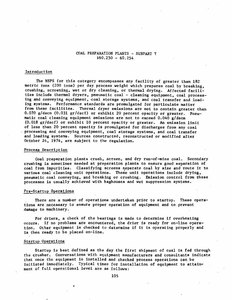
Introduction
COAL PREPARATION PLANTS - SUBPART Y §60.250 - 60.254
The NSPS for this category encompasses any facility of greater than 182 metric tons (200 tons) per day process weight which prepares coal by breaking, crushing, screening, wet or dry cleaning, or thermal drying. Affected facilities include thermal dryers, pneumatic coal - cleaning equipment, coal processing and conveyin~ equipment, -coal storage systems, and coal transfer and loading systems. Performance standards are promulgated for particulate matter from these facilities. Thermal dryer emissions are not to contain greater than 0.070 g/dscm (0.031 gr/dscf) or exhibit 20 percent opacity or greater. Pneumatic coal cleaning equipment emissions are not to exceed 0.040 g/dscm (0.018 gr/dscf) or exhibit 10 percent opacity or greater. An emission limit of less than 20 percent opacity is promulgated for discharges from any coal processing and conveying equipment, coal storage systems, and coal transfer and loading systems. Sources constructed, reconstructed or modified after October 24, 1974, are subject to the regulation.
Process Description
Coal preparation crushing is sometimes coal from impurities.
plants crush, screen, and dry run-of-mine coal. Secondary needed at preparation plants to ensure good separation of Classifying screens separate coal by size and route it to
\
various coal cleaning unit operations. TheSe unit operations include drying, pneumatic coal conveying, and breaking or crushing. Emission control from these ~rocesses is usually achieved with baghouses and wet suppression systems.
Pre-Startup Operations
There are a number of operations undertaken prior to startup. These operations'are necessary to ensure proper operation of equipment and to. prevent damage to machinery.
For driers, a check of the bearings is made to determine if overheating occurs. If no problems are encountered, the drier is ready for on-line operation. Other equipment is checked to determine if it is operating properly and is then ready to be placed on-line.
Startup Operations
Startup is best defined as the day the first shipment of coal is fed through the crusher. Conversations with equipment manufacturers and consultants indicate that once the equipment is installed and checked process operations can be initiated immediately. Typical times for installation of equipment to attainment of full operational level are as follows:
105
,

Equipment
Crushers Driers Total Plant (large)
Time
2 weeks, 1-4 days, 1-3 months.
Based on the aforementioned data, commencement of process operations is B reasonable date for startup. Testing at full operational level can be achieved within 180 days of this date with no anticipated problems.
106

REFERENCES
1. Personsl communication with Mr. D. Graveman, American Pulverizer Company, St. Louis, Missouri. 12 March 1979.
2. Personal communication with Mr. Benning, Dravo Corporation, Philadelphia, Pennsylvania. 13 March 1979.
3. Personal communication with Mr. Carpenter, Jeffrey Manufacturing Co., Columbus, Ohio. 12 March 1979.
4. McCandles, L.C. and R.B. Shaver. Assessment of Coal Cleaning Technology: First Annual Report. EPA-600/7-78-150, U.S. Environmental Protection Agency, Research Tr~ang1e Park, North Carolina, July 1978.
107

Introduction
FERROALLOY PRODUCTION FACILITIES - SUBPART Z §60.260 - 60.266
The Standards of Performance for Ferroalloy Production Facilities affect: (1) electric submerged arc furnaces which produce silicon metal. ferrosilicon, calcium silicon, silicomanganese zirconium, ferro~hrome silicon. silvery iron, h1gh-carbon ferrochrome, charge chrome. standard ferromanganese, silicomanganese, ferromanganese silicon, or calcium carbide; (2) and dust handling equipment. The pollutants regulated are particulates and carbon monoxide.
Owners or operst.ors are not permitted to discharge from any electric "submerged arc furnace any gases into the atmosphere which: (1) exit from a control device and contain particulate matter in excess of 0.45 kg/MW-hr (0.99 lb/MW-hr) while silicon metal, ferrosilicon, calcium silicon, or silicomanganese zirconium is heing produced. (2) exit from a control device and contain particulate matter in excess of O.23kg/MW-hr (0.51 lb/MW-hr) while high-carbon ferrochrome. charge chrome, standard ferromanganese, silico-manganese, calcium carbide, ferrochrome silicon, ferromanganese silicon or silvery iron is produced. (3) exit from a control.device and exhibit 15 percent opacity or greater, (4) exit and escape the capture system and are visible without the aid of instruments (applies only during periods when flow rates are being established), ('» escape the capture system at the tapping station and are visible without the aid of instruments for more than 40 percent of each tapping period. There are no Hmitations on visible emissions when a blowing tap occurs (requirements apply only during periods when flow rates are being established).
Dust handling equipment emissions are limited to less than 10 percent opacity. Carbon monoxide from any electric submerged arc furnace is limited to less than 20 percent by volume (dry basis). A continuous monitoring system is required to monitor opacity of emissions discharged from the control device.
Sources constructed, reconstructed or modified after 21 October 1974 are Rubject to the regulations.
Process Description
Ferroalloy il'l a material consisting of iron and one or more other metals. Ferroa] loys are used in steel .production as alloying" elements and deoxidants. There are three types of ferroal10ys: silicon-based; manganese-based; and chromium-oased alloys. There are four major procedures used to produce ferroalloy: blaRt furnaces, electrolytic depoSition, alumina si1ico-thermicprocess, and electric smelting. However, the primary system used is electric smelting.
lOB

Seventy-five percent of all ferroalloys are produced in electric smelting furnaces, of which electric submerged-arc open type is the oldest, simplest and most widely used. The alloys are made in the electric furnaces by reduction of suitable oxides. For example, in the production of ferrochromium, the charge may consist Of chrome ore, limestone, quartz coal, wood chips, and scrap iron. The production of ferroalloy requires a number of steps from materials handling to smelting to shipment. Figure 24, illustrates a schematic diagram of the system involved.
Experts in the electric submerged arc furnace industry indicated that there are no new plants presently under construction and that there are none planned for the next 5 to 10 years.
Pre-Startup Operations
The pre-startup operation of a ferroalloy facility involves the coordination of numerous systems. Each unit must undergo its own pre-startup checks and startup procedures before it can be integrated with the rest of the system. Very often minor malfunctions and defects in units are. the primary reason for delays in meeting the startup and maximum production dates. Some of the units which may have problems are crushers, scales, feeders, castings and pollution control units .. At this time in the pre-startup proced.ure, most of the units are checked-out without a material load. The primary unit used in the production of ferroalloy is the electric submerged arc furnace. The furnace ranges in size from 6.1 to 12.2 meters (20 to 40 feet) in diameter with a height of 4.6 to 6.1 meters (15 to 20 feet). The furnace has a 5 cm (2 in.) thick steel shell and is lined with brick refractory. Between the refractory brick and the steel shell is a carbon liner. Electrical power transmitted through electrodes bearing down on resistant coke provides the heat for smelting in the furnace. Systems and components that are given special attention relative to the electric furnace pre-startup operations are: water cooling, water treatment, roof and wall structures, air pollution controls, electrode rigging, electrode slipping and backing machanisms, tapping, lattle, crane movement, and all electrical, mechanical and hydraulic subsystems.
The first major step in pre-startup of an electric submerged arc furnace depends on the type of electrodes used. Internationally, there are two types of electrodes that may be used in producing ferroalloys: prebaked and self-baked~ The pre-baked electrode, which is usually manufactured elsewhere, is a hard rod-shaped baked carbon/silicon body ranging in size from 0.3 to 61 cm (1/8 to 24 in.) in diameter and lengths up to 244 cm (96 inches). The self-baked electrode is a pasty mixture of carbon and silicon which is baked into a hard. rod-shaped carbon body within the electric submerged arc furnace (this report examines only the self-baked electric submerged arc furnace because they are primarily used in the United States).
The first pre-startup step is the baking of the pasty carbon-silicon mixture into .a hard, rod-shaped body. This step is called <bake-in. The carbon material is contained in a thin gauge, hollow electrode steel cylinder 15 to 18 meters (50 to 60 feet) in height. At bake-in, a pre-baked electrode is inserted Into the cylinder followed by a homogeneous mixture composed of coal, metAllurgical coke, lampblack, coal tar pitch, and petroleum coke. The furnace
109

I-' I-' o
..
TO BAGttOUSE OR SCRUBBER -
Figure 24. Schematic diagram of the ferroalloy production process. 7

is then loaded with a 0.2 m3 (55 gallon) drum of coke (the conductive material). The electrode cylinder and content is lowered into the coke drum bearing down with electric power. The system electrodes are energized with low voltage, wherein heat is created by electrical resistance from the coke. This heat bakes the carbon paste in the upper portion of the cylinder. Voltage is increased and more coke is added, thus increasing the furnace temperature and baking more of the carbon mixture in the column. The bake-in will continue until about 4.6 meters (15 feet) of carbon mixture in the column is baked to a hard carbon body. As the pre-baked electrode is consumed (-2.5 cm or 1 in. per hr), the self-baked electrode will slip down bearing on the coke. More carbon mixture would then be added to the column to replace the consumed portion of the electrode. Once the bake-in is completed, pre-baked electrodes are not used again. Pre-baked electrodes are only used during bake-in (startup). If pre-baked electrodes are not used during bake-in, the entire electrode column is filled with carbon paste and baked with an au~iliary fuel (oil or gas). The entire bake-in takes 2 weeks time while curing the furnace takes another 2 to 3 weeks, and heating the furnace to operating temperatures takes about I to 2 weeks. During the bake-in, curing, and heatup, the furnace will normally be shutdown 5 to 10 times for repair of malfunctions, defects and especially to tighten the bus bar. Shutdown and startup will only take a few hours unless there is a major malfunction. The total pre-startup operation may consume a 5 to 7 week period.
Startup Operations
Up to this time, no metal has been introduced into the furnace. Upon reaching operating temperatures of 2760 to 33l6°C (5000 to 60000 F), metal is slowly introduced to the furnace. The furnace is stabilized and then more charge is added. The technique will continue until the furnace has attained rated capacity. If everything operates smoothly, the furnace should reach maximum production in six months. However, in ferroalloy production, there are numerous units involved where many problems can develop. Experience has shown that most plants take 6 to 12 months to reach maximum production. Two major problems are the integration of all units and the training of operators. If any units, systems or operators are not running at rated capacity, the maximum production rate cannot be reached. Most furnaces operate at 50 percent maximum production the first year and in succeeding years production will increase to about 90 percent. The first year of operation is usually plagued with numerous malfunctions and breakdowns. The official startup date for an electric submerged arc furnace should begin when metal is first introduced into the furnace.
111

REFERENCES
1. Personal Communication with Dr. C.R. Allenback, Union Carbide, Niagara Falls, New York, May 9, 1979 •
. 2. Personal Communication with Dr. R. Persons, Union Carbide, Niagara Falls, New York, May 9, 1979.
3. Communication with Foote.Mineral Company, Exton, Pennsylvania, May 8, 1979.
4. Communication with Paul Blum Company, Inc., Buffalo, New York, May 8, 1979.
5. Personal Communication with Dr. Watson, Ferroalloy Association, Washington, D.C., May 9', 1979.
6. Personal Communication w1th Mr. John Persons, Lectromelt, Pittsburgh, Pennsylvania, May 8, 1979.
7. Dealy, James and Arthur Killin. Engineering and Cost Study of the Ferroalloy Industry, EPA 450/2-74-008. U.S. Environmental Protection Agency. 1974.
112
IRON AND STEEL PLANTS: ELECTRIC ARC FURNACES - SUBPART AA §60.270 - 60.275
Introduction
Affected facUities under this subpart include the electric arc furnace (EAF) and associated dust-handling equipment. Electric arc furnace means any furnace that produces molten steel by melting charge material with electric arcs from carbon electrodes. Dust-handling equipment means any equipment used to handle particulate matter cnllected by an EAF control device.
The emission standard promulgated under this subpart limits particulate matter discharge from an EAF control device to 12 mg/dscm (0.005'2 gr/dscf). In addition, control device exhaust stacks shall not exhibit 3 percent opacity or greater. EmLasinns from the dust-handling equipment shall not be ~ 10 percent opacity.
With respect to the EAF melt shop, emissions from the shop are limited to o percent .opacity except during:
• charging periods, when the shop opacity may be greater than zero but less than 20 percent.
• tapping periods, when the shop opacity may be greater than zero but less than 40 percent.
Where the EAF capture system is operated with the shop roof closed during charging ,and tapping/and emissions to the atmosphere are prevented until the roof is opened after completion of the charge or tap, shop opacity standards shall apply when the roof is opened and shall continue to apply for the time defined by the charging and/or tapping periods. Continuous opacity monitoring of emissions from the control device is required. Affected facilities constructed, reconstructed or modified after October 21, 1974, are subject to the requirements of this subpart.
~ess Description
Electric arc furnaces (EAFs) for the production of steel have been in use sLnce 1906. The recent demand for higher quality alloy and stainless steels is responsible for increasing use of EAFs. It has been estimated that 20 percent of the steel produced in the U.S. in' 1976 was made in EAFs and as open hearth units are shut down, EAF units will see increasing use.
113
EAFs utilize electric current as a source of heat to melt scrap metal. The process begins when scrap metal and alloys are charged to the furnace. Following charging the electrodes are lowered into the charge to start the initial "horedown" period. During boredown, a pool of molten metal is formed on the surfnce of the scrap charge. From this time on, the charge is melted by a combination of heat from the arc, heat radiated from the bottom of the veHsel, and by the reslstance of the scrap to the current. Occasionally, the boredown period is interrupted and additional scrap and/or fluxing agents are added to the mixture. 'When the charge is completely melted, the steel and slag (the solid waste formed during melting) are tapped into ladles and pots respectively. Molten steel is then either further processed to produce stainless steel, poured into ingot molds or sent to a continuous caster.
Pre-Startup Operations
There are several operations involved in the pre-startup process for electric arc furnaces. Mechanical and electrical equipment must be checked to ensure that they are fully operational. Lastly, the furnace refractory is preheated and checked. Once these steps are completed, the furnace is ready for operation.
Startup Operat.tons
InUial startup involves charging the furnace and initiating boredown. The time required to attain maximum production depends on furnace size. Conversationswlth industry personnel indicate that for most furnaces full production level can be achieved in 6 months. Based on this, the startup date is best defined aR the time of the first 'furnace heat. However, if 'during startup operational problems are encountered which lsignificantly alter normal cycle times, representative performance test data might be unattainable until the problems are straightened out.
114

REFERENCES
1. Personal communication with Mr. J. Haley, Pullman-Swindell, Pittsburgh, Pennsylvania. 13 March 1979 •
. 2. Personal communication with Mr. J. Galbreath, Whiting Corp., Harvey, Illinois. 13 March 1979.
3. U.S. Steel. The Making, Shaping and Treating of Steel. Herbick and Held. Pittsbur'gh, .Pennsylvania. 1971.
115

Introduction
KRAFT PULP MILLS - SUBPART BB §60.280 - 60.285
The facIlities of a kraft pulp mill covered under this subpart are: digester system, brown stock washer system, multiple-effect evaporator system, black liquor oxidation system, recovery furnace, smelt dissolving tank, lime kiln, and condensate stripper system. In pulp mills where kraft pUlping is combined with neutral sulfite semi-chemical pulping, the provisions of this 9ubpart are applicable when any portion of the material charged to an affected facility is produced by the kraft pulping operation. Facilities constructed, reconstructed or modified after September 24, 1976, are covered by the regulation.
A particulate emission limit of 0.10 g/dscm (0.044 gr/dscf) corrected to 8 percent oxygen and an opacity of less than 35 percent have been set for the recovery furnace. Emissions from the smelt dissolving tank are limited to 0.1 g/kg black liquor solids (dry weight) or 0.2 lb/ton black liquor solids (dry weight). For the lime kiln, the limit is 0.15 g/dscm (0.067 gr/dscf) corrected tolO percent oxygen when burning gaseous fossil fuel and 0.30 g/dscm (0.13 gr/dacf) corrected to 10percent oxygen, when burning liquid fossil fuel.
Total reduced sulfur (TRS) means the sum of the sulfur compounds-hydrogen sulflde, methyl mercaptan, dimethyl sulfide, and dimethyl disulfide - which are released during the kraft pulping operation. An emission limit of 5 ppm of TRS by volume on a dry basis corrected to 10 percent oxygen has been established for the dlgester system, brown stock washer system, multiple-effect evaporator system, hlack liquor oxidation system and condensate stripper. This emission limit remains in effect unless one of the following conditions are met: (1) the gases are combusted in a lime kiln, (2) the gases are combusted in a recovery furnace, (3) the gases Bre combusted with other waste ·gases in an incinerator or other device not subject to the standard and are subjected to a minimum temperature of 6490 C (l2000 F) for at least 0.5 second, (4) it has been demonstrated to the administrator's satisfaction that incineration of TRS from the black liquor oxidation system or brown stock washer system is technologically or economically not feasible. or (5) the digester, brown stock washer, condensate stripper or black liquor oxidation system are controlled by a means other than combustion whereby TRS emissions do not exceed 5 ppm by volume on a dry basis corrected to the actual oxygen content of the untreated gas stream.
1':miRsion limits of 5 ppm and 25 ppm TRS by volwne on a dry basis, corn!cted to 8 percent oxygen have been established for any straight and cross recovery furnaces respectively. For the smelt dissolving tank, the.TRS emission limit has heen set at 0.0084 g/kg black liquor solids (dry weight) or
116

0.0168 lh/ton liquor solids (dry weight). Total reduced sulfur emission limits from the lime kiln have been set at 8 ppm by volume on a dry basis, corrected to 10 percent oxygen.
Continuous monitoring requirements apply to recovery furnace opacity and to TRS emissions from lime kilns, recovery furnaces, digester systems, brown stock washer systems, multiple-effect evaporator systems, black liquor oxidation systems and condensate stripper systems.
Process Description
The first step of kraft pulping is to prepare the wood for cooking. Logs are debarked, chipped and screened prior to being fed to a digester. Some mills will operate their own wood processing facilities, whereas others will purchase wood chips from an external source. The wood chips placed in the digester are cooked in a "white liquor," a water solution of sodium sulfite (Na&~) and sodium hydroxide (NaOR), at a temperature of 170 to 17SoC (338 to 347 F) and pressure of 689 to 931 kPa (~OO to 135 psi). The white liquor chemically dissolves the lignin of the wood, freetng the cellulose fibers. The cooking process, which can be b~tch or continuous, usually lasts from 2 to 3 hours. At the completion of th~ cook, the charge is blown into tanks to release steam and other gases. The cellulose (pulp) is then separated from the spent cooking liquor by filtration. At this point, the pulp is referred to as brown stock and the spent cooking liquor is called weak black liquor. After filtration, the brown stock is washed with water and passed through knotters, rifflers and screens which sieve out small pieces of uncooked wood. Once screened, the pulp is filtered and sent on to thickeners. From here, the pulp can go to a bleach plant or to paper machines for final,processing.
A major portion of the kraft pUlping process is devoted to the recovery of cooking liquor and heat. The weak black liquor is concentrated in multipleeffect evaporators to about 65 percent solids and then burned in recovery furnaces. Steam generated by the furnaces is, used for process operations throughout the plant.
Basically, there have been only two types of recovery furnaces used in the kraft pulping industry: the direct-contact evaporator system and the more recent indirect-contact system. The former type requires the oxidation of the concentrated black liquor prior to combustion to reduce TRS emissions. One reference source contacted stated that most new mills being built today and in the future will be using the indirect-contact evaporator sy~tem.
The residue resulting from burning the black liquor, called smelt, is dissolved in.water to form "green liquor," an intermediate solution used to regenerate white liquor. Once formed, the green liquor is transferred to a causticizing tank where quicklime (CaO) is added to convert the sodium carbonate (Na2C03) to NaOR. The formation of NaOR completes the white liquor regenerative cycle. The calcium carbonate (CaC03) slurry (40 to 45 percent water), generated during the causticizing process, is converted to CaO by calcina-tion in a rotary kiln. The CaO is then reused in the process.
117

A condensate stripping system, employing either air or steam in a stripping column, may be used to control TRS compounds emitted from the digester systems and multiple~effect evaporators. TRS compounds emitted from other facilities are usually controlled by process combustion, condensers, incinerators, or absorption trays. A general flow diagram of the kraft pulping process is presented in Figure 25.
Pre-Startup Operations
Before being connected to form the contiguous operation of a kraft pulp mill, each affected and nonaffected facility is subjected to extensive shakedown procedures. Electrical and instrumentation systems are thoroughly checked before any piece of equipment is actuated. Process equipment is examined for proper installation, clearance,and rotation. Transfer lines are checked for free passage, leaks, and correct distribution. In addition, pieces of equipment which are operated at elevated temperatures and pressures ate tested initially for leaks and expansion with hot water and then with steam, which is provided by the power boilers or recovery furnaces (fired with auxiliary fuel).
The three most important facitities affected within a kraft pulp mill, are: the digester sys~ems, recovery furnaces"and lime kiln. Initial shakedown operations for the digesters involves passing hot water through the units (including the blow tanks) to check seals and as a preliminary rinse. Next, steam is passed through the digesters for further cleaning, and to test expansion joints. A final shakedown step prior to actual startup is to feed chips and steam to the digester to simulate a cook. The partially cooked chips will be passed to the blow tank to assure proper dIstribution and free passage of material. This last step may last !from one to eIght hours.
i
Pre-startup operations of the recovery furnaces are similar to those of an industrial boiler. These procedures include cleaning the inner walls of the furnace; boilout (which removes grease and other d~posits from the water and steam tubes); and testing of components with respect to thermal expansion, mechanical stresses, corrosion resistance, structural soundness, warping, and leakage. Process controls, sensors, moni·tors, loading switching,safety interlocks, and the steam distribution system are also checked prior to startup. In addition, fans and pumps are run, dampers are stroked and burners are test fired. AU furnace tests are conducted with auxiliary fuels such as oil or gas.
The startup of a recovery furnace is subject to codes set forth by the Black Liquor Recovery Boiler Advisory Board, a self-governing body made up of membe,:'s from the kraft pulp mill industry. 'Some of the requirements of the board are that certain welds be radiographed to assure integrity, hydrostatic pressure tests be conducted and certain safety systems be Installed and thoroughly checked before the furnace is started. The shakedown period for recovery furnaces will normally last from two to seven days. Electrostatic preCipitators nre typically used to control particulate emissions from recovery furnaces, whereas absorption-type scrubbers are used to control reduced sulfur compounds.
118

I
WOOD
WHtTl LIOUO ,N.OH. N'Z'
NONCONOCNIAILIII
CONDINIATl
OIOUT'"
VCNT GAlli
YlNT GAlli
t
PIILP TO .... "I"LI.I,
KNOTTI.I,_ ICItIiNI
WAT'"
NONCONOIMSULIS tX"AUIIl GAS
\ 1 ____ t _' _ ,CONOINIATI
1- -I I I I ,
STACK --,
1 I P---~----~ ,ILAC" I
RICOV'''Y 'U"NACI
LIQUO" I '. OXIDATION I TAN", I'
IYITUI ~:;..:;:;r.:-\I 'OP TI ON ALI I ... 'I
vln _--...... ----11.., GASIS
1 _______ I
MULTIPLI IPPICT IVAPO"ATO". IYITIII .
VINT GAllS
WATU INILT DISSOLVING TANK L
__ • TO TRIATMINT POND
''''IN LIQUOR
- 'uiL
" W."ITI CAuITICIZING LIQUOR TANK LIMI
(1tICYCL!. TO ~--,-------~ Dillin",
Figure 25.
CALCIUM CAItIONATI ILu,un
Flow diagram for Kraft pulping process operations. 2
119
UHAUIT GAlli
The pre-"startup operations of a kraft pulp mill lime kiln are similar to those of a rotary kiln used in the manufacture of lime. Once the kiln has been erected and before it is bolted down, various tests are conducted to check its alignment and rotation. Once the kiln passes these preliminary tests, it is secured and rechecked for alignment and rotation. A third examination is made when heat is first introduced to the kiln.
The most important pre-startup operation of the kiln is the seasoning or drying out of the brick refractory lining. New refractory usually contains residual amounts of water which must be driven out before the lime slurry can be fed into the kiln. The drying out process is slow, requiring a gradual warming of the bricks to prevent cracking or loosening. The kiln seasoning process normally takes 3 to 5 days.
Once the refractory has been properly seasoned and the burners and fuel supply lines have been checked out, the kiln is ready to receive the lime slurry. Lime kilns operated at kraft pulp mills are usually fired with gas or oil. High energy venturi scrubbers are normally used to control kiln emissions.
Startup Operations
The performance of a facility affected by this subpart is dependent upon process operations upstream and downstream of the particular unit. Six major operations within 8. kraft pulp mill are the: power boilers, digester system, recovery furnaces, lime kiln, bleach plant, and paper machines. The startup of a mill requires the operation of at least the first four of these processes. Some mills will not operate bleach facilities nor paper machines. The power boilers, not affected under this subpart, are the first operations to be brought on line.
Startup of the facilities affected under this subpart is considered to be when wood chips and white liquor are first fed to the digesters with the intent to produce pulp. Mill operators contacted stated that it may t.ake from twelve to twenty-four hours from the time the first cook is initiated until recongnizable pulp comes out of the thickeners. The first pulp produced is not of·any commercial or production value. Due to the large capital outlay and high daily· operating costs, this situation will not last long and mill operators will concentrate their efforts on fine tuning process equipment in order to produce useable pulp as soon as possible.
Once the first cook has been initiated, it will take a day or two before enough black liquor is produced to fire in the recovery furnace. Likewise, it will be one to two days after black liquor is first burned b"efore enough lime slurry is generated from the causticizing tank to be fed into the lime kiln. Because white liquor will not be generated from process operations until two to four days after commencement of the initial cook, the white liquor and caustic (lime) must be purchase9 or obtained from some other source in order to start the pulping process. Once the chemical recovery cycle has been completed, it becomes almost entirely se1f-sustaining. In summary, it normally takes from two to four days after initial startup; i.e~, the introduction of wh Lte liquor and wood chips into the d:f.gester, before all the affected facilities of a kraft pulp mill become operat:1.onal.
120

Because kraft pulping is a complex process involving chemical reactions and several different and sometimes technologically new pieces of equipment, it may and probably will take longer than 180 days after initital startup before a mill is operating at or near its maximum production rate. Several reference sources contacted stated that it normally takes a year or more for a mill to reach its maximum production rate. One source stated, however, that barrirtg major mechanical failures or the debugging of newly developed process equipment, a mill could achieve its maximum production rate within 180 days. Due to the uncertainty in the amount of time required to achieve the maximum production rate of the affected facility, multiple testing, once prior to the l80-day limit and once after achieving maximum production capacity may be reqUired. It is noted that for certain industrial categories such as kraft pulp mills, the tmplementation and enforcement of Section 60.8 of CFR Part 60 may have to be carried out on a case-by-case basis •
•
121
REFERENCES
1. Environment Reporter, Bureau of National Affairs, Inc., 1978, New Source Performance Standards Subpart BB, Standards of Performance for Kraft Pulp Mills.
2. Standards Support and Environmental Impact Statement Volume I: Proposed Standards of Performance for Kraft Pulp Mills, 1976. U.S, Environmental Protection Agency Office of Air and Water Management. Research Triangle Park, North Carolina. EPA-450/2-76-014a.
3. Personal Communication with representative of Technical Association of Pulp and Paper Industry, Atlanta, Georgia, April 26, 1979.
4. Personal Communication with Mr. Eddinger, Industrial Studies Branch, U.S. Environmental Protection Agency, Research Triangle Park, North Carolina, April 27, 1979.
S. Personal Communication with Mr. Landegger, Black Clawson Company, New York, New York, April 27, 1979.
6. Personal Communication with Mr. Dickenson, Babcock and Wilcox, North Canton, Ohio, April 27, 1979.
7. Personal Communication with Mr. Nicholson, Weyerhauser Company, Tacoma, Washington, April 27, 1979.
8. Personal Communicaiton with Mr. Elam, Black Clawson Company, Middletown, Ohio, April 27, 1979.
9. Personal Communication with Mr. Salkowski, Boise Cascade Corporation, St. Helens, Oregon, April 30, 1979.
10. Personal Communication w~.th Mr. Milow, Combustion Engineering, Boston, Massachusetts, April 30, 1979.
11. Personal Communication with Mr. Sut ter, St. Regis Paper Company, Jacksonville, Florida, April 30, 1979.
12. Personal Communication with Mr. Derby, St. Regis Paper Company, Monticello, Mississippi, April 30 t 1979.
13. Personal Communication with Mr. Belas, Air Enforcement Branch, U.S. Environmental Protection Agency, Region IV, Atlanta, Georgia, April 30, 1979.
122

14. Personal Communication with Mr. Tretter, Georgia-Pacific Corporation, Atlanta, Georgia, May 2, 1979.
123
Introduction
GRAIN ELEVATORS - SUBPART DD §60.300 - 60.304
The sources covered under this subpart are grain terminal elevators which have a permanent storage capacity of over 88,100 m3 (2.5 million U.S. bushels) and grain storage elevators located at any wheat flour mill, wet corn mill, dry corn mill, rice mill, or soybean oil extraction plant which have apermanent storage capacity of 35,200 m3 (1 million bushels). The facilities affected under this category are: truck loading and unloading station, railcar loading and unloading station, barge and shiploading and unloading station, grain dryer, and all grain handling operations. Standards are set for captured emissions and uncaptured (fugitive) emissions.
All captured emissions are passed through a stack or control device prior to being emitted to the outside air, and must meet an opacity standard of o percent. All captured emissions except those from a grain dryer (column dryer or rack dryer) must also meet a particulate standard of 0.023 g/dscm (0.01 gr/dscf). A fugitive emission opacity limitation has been set at 5 percent for any individual truck unloading station, or railcar unloading or loading station; 0 percent for any grain handling operation; 10 percent for any truck loading station; and 20 percent for any barge or shiploading station. Sources constructed, reconstructed or modified after August 3, 1978, are subject to the regulations.
Process Description
Prior to unloading, grain received is graded for quality and dust content, and then weighed. The grain is then unloaded by direct dumping or conveying (e.g., pneumatic, belt, bucket, or chain) into a receiving hopper and then· transferred to a surge (garner) bin. From the surge bin the grain is lifted to the headhouse, the top of the elevator. At the headhouse, the material is distributed to one of several storage bins. Certain incoming grains, however, may need to be cleaned and dried before they can be stored.
Cleani.ng is required when incoming grain contains a high· percentage of crop soil, weeds, insects, stones and/or stalks. The first step in cleaning (scalping) is to pass the grain through a coarse mesh screen to remove large foreign matter. Aspiration, the next step, is carried out to remove the fine foreign matter from the grain. The process involves directing air crosscurrently
124

and countercurrently through dispersed falling grain. The third and usually final step is to size the grain ~sing a stack of vibrating screens. These three grain cleaning steps can be operated separately or together as one contiguous system. Grain cleaning may occur before and/or after grain storage.
To prevent spoilage, certain grains, including barley, oats, wheat, corn and sorghum, must be dried to a specified moisture content before they can be stored for any length of time. Drying facilities are used predominately during the harvest season. An alternative to drying is grain blending, a practice of mixing incoming grain which does not have an excessively high moisture content with previously dried grain.
Because grain fermentation and heat build up. may occur in long-term storage , " " bins, it becomes necessary to turn the grain. to prevent deterioration. Grain
turning involves transferring material from the bottom of one bin to the top of another bin. Turning may be required several times a year depending on moisture content, grain temperature, and the length of time the grain has been stored without aeration.
Prior to grain load out, material will be weighed and cleaned if not done 80 previously. The grain is then transferred from the weigh station to an awaiting carrier vehicle via telescopic piping. A general process flow diagram for grain terminal elevators is presented in Figure 26. Particulate emissions from affected facilities are typically controlled by mechancial separators and baghouses.
Pre-Startup Operations
.Because of the various affected unit operations associated with grain terminal and storage elevators, many preliminary shakedown procedures must be undertaken. Checkout procedures common to all the affected facilities are: veri.fication of all electrical circuits and connections, checking clearance of moving equipment, bumping of motors and pumps, assuring correct rotation of equipment, calibration of scales and instrumentation, and monitoring of air pollution control devices.
Equipment checkout procedures unique to unloading, distribution and loadout facilities are: free passage through transferring legs (e.g., pneumatiC belt, or bucket conveyors), co+rect movement and discharge of distributors and trippers of the headhouse and process control systems. Equipment employed in grain cleaning are checked out for clearance, alignment, and free flow of material. For the dryers, equipment alignment and rotation, burners, fuel supply lines, air leakage, and temperature and air flow controls are checked out before the equipment is actuated.
Process equipment will be tested individually at first, then as integral parts of an affected facility. Dry runs will be conducted to make sure process equipment is functioning properly before grain is intorduced into the system. After all equipment has been checked out, trial runs will be made handling grain. The equipment is tested under various loads to recheck alignment, rotation, clearance, free passage of conveying lines, the distribution system, belt B~retching, and conveyor speeds and to break in air pollution control equipment.
125

I-' N 0\
TRUCK
o ... 0'" z· -II: ~O ... 1-u C ... > .:'" J ...
GRAIII
SURGI ~----~.t~GARNER'
liN
• ... ... .: o IC > ... ... ...
DISTRlaUTOR AND TRI .... I ..
GRAIN STORAG
IINS
Figure 26. Process flow diagram for grain terminal elevators.
TRUCK
The facUities are tested initially at a minimum load then gradually brought up to or near design rates. The grain used for equipment shakedowns may already be on-site for a modified source, or for a newly constructed elevator a small amount of grain may have to be purchased from a local farm or country elevator. Once each affected facility has been successfully tested under actual conditions, it is considered to be "ready for business," and capable of receiving grain. Pre-startup shakedown operations may last from less than I to 3 months depending on the function of the subject elevator.
Startup Operations
The startup date for each of the affected facil~ties of a grain terminal elevator or grain storage elevator will vary depending on the source's function, type of grain received, time of year, and climatic conditions during harvesting. Because of inherent flexibility of a grain elevator, some facilities will be brought online while others are still under construction, being debugged or idle. Once an elevator starts receiving grain for processing, or export, the minimum number of facilities required to be operated concurrently are the grain unloading stations, bin distribution system and loadout stations. These opera-tions, however, do not have to be run simultaneously. .
Grain cleaning is a variable operation which depends on the quality of the incoming material and its end use. Grain drying is somewhat, of a seasonal operation. Typically, grain harvested during the late fall and early winter months of the year require some drying before ~torage. Grain drying, however, may also be required at other times Of the year, when an elevator receives a shipment of material high in moisture content.
Startup is considered to be when the first shipment of grain is unloaded, handled, cleaned, dried, or loaded after the affected facility is "ready for business." As stated previously, the affected facility is ready for business when process equipment have been tested successfully with grain under trial conditions at or near design capacity. As an example, a column dryer could be erected and run successfully under actual operating conditions by March 1, on March 2, it would be ready for business, but not begin· drying grain until October 1. In this example~ the startup date would be October 1. This scenario could apply to all affected facilities of a grain terminal elevator or grain storage elevator. Startup for each operation occurs when grain, which will be exported or processed in a mill,for commercial sale, first enters the faCility, thus initiating the generation of particulate matter~ Consequently, each affected facility will more than likely have a different startup date.
In regards to performance testing of air pollution control deVices, the attainment of maximum production rates does not depend solely on the performance of process equipment but in part on the incoming grain supply. It is conceivable that an affected facility of an,elevator may not reach its maximum production rate within 180 days of initial startup. A well operated elevator, however, would not fall into this category.
127

REFERENCES
1. Environmental Reporter, Bureau of National Affairs, Inc., 1978, New Source Performance Standards Subpart DD, Standards of Performance for Grain Elevators.
2. Personal Communication with Mr. John Healy, Grain Elevator and Processing Society. Minneapolis, Minnesota, April 23, 1979.
3. Personal Communication with Mr. Robert Hendricks, Central Soya, Fort Wayne, Indiana, April 23, 1979.
4. Personal Communication with Mr. Sims Roy, U.S. EPA Standards Development Branch, Raleigh, North Carolina, April 23, 1979.
5. Personal Communication with Mr. Leroy Funk, Carter-Day Company, Minneapolis, Minnesota, April 23, 1979.
6. Personal Communication with Mr. Dick Wilbur, Cargill, Inc., Minneapolis. Minnesota, April 24, 1979.
7. Personal Communication with Mr. Stan Gasawski, Continential Grain Company, St. Louis, Missouri, April 24. 1979.
8. Personal Communication with Mr. Hollingsworth, Aeroglide Corporation, Raleigh, North Carolina, April 24, 1979.
9. Personal Communication with Mr. R. Gillund, Mathews Company, Crystal Lake, Illinois, April 24, 1979.
10. Personal Communication with Messrs. James Appold and Fred Wolf. The Andersons, Maumee, Ohio, April 24, 1979.
11. Personal Communication with Messrs. Al Colby and Wes Weber. Archer Daniels. Midland Processing Company, Decatur, Illinois, and St. Louis', Missouri, April 25, 1979.
128
I
Introduction
LIME MANUFACTURING PLANTS - SUBPART HH §60.340 - 60.344
The facilities subject to Standards of Performance for Lime Manufacturing Plants are: rotary lime kilns and lime hydrators. A rotary lime kiln is a unit with an inclined rotating drum which is used to produce a lime product from limestone by calcination. A lime hydrator is a unit used to produce a hydrated lime product. The pollutant regulated is particulate matter. Emission limits established for rotary ·kilns and hydrators are 0.15 kilogram per megagram of limestone feed (0.30 lb/ton) and 0.075 kilogram per megagram of ·lime feed (0.15 lb/ton) respectively. In addition, an opacity limitation of less than 10 percent has been established for rotary lime kiln emissions. Continuous monitoring of rotary kiln opacity is requi·red, except when using a wet scrubber emission control device. Subpart HH does not apply to facilities used in the manufacture of lime at kraft pulp mills. Sources constructed, reconstructed or modified after May 3, 1977, are subject to the regulation.
Process Description
The sequence of operations in the production of lime are: 1) quarrying the limestone, 2) crushing and sizing, 3) conveying, 4) calcination by rotary kiln,S) processing the quicklime (the product of the kiln) by hydration, 6) milling/sizing, and 7) packaging (bulk or bag). As mentioned above, the lime manufacturing standard covers only the calcination and hydration operations. These two operations are depicted in Figure 27. "Limestone" means calcitic and dolomitic limestone, whereas "Lime Product" means the product of the calcination process including but not limited to calcitic lime, dolomitic lime, and deadburned dolomite.
Calcination
A rotary kiln is basically a furnace consisting of a heavy steel shell lined with refractory brick. Kilns are normally fired with one or more of the following fuels: natural gas, fuel oil, or pulverized coal or coke. The kilns are normally installed at inclines of 3-50 on four to six foundation piers and revolve on trunnions at 30-50 seconds per revolution. Rotary ~ilns will vary in size ranging from 2 to 5 meters (6.5 to 16 feet) in diameter to 18. to 183 meters (59 to 600 feet) in length.
Sized limestone is fed into the elevated end of the kiln and travels down the length of the kiln towards the firing end. The material is heated to a temperature of 11000 C (20000 F) which chemically breaks down the limestone (CaC03) to produce quicklime (CaO) releasing CO~. Particulate laden gas flows counter-
129

I-' W o
AIR ... ,.
LIME
w PROOUCT COOLER
COAL a AIR
w
SIZED STOllE
~
w~nJ GAS ,.n.~ , ~
't G~S
ROTARY KILN '--__ ........"tE STONE
GAS TO ATMOSPHERE
FAN
lIAS TO A1'IIOIIPMERE
+
GAS ~ COIITROL I. ) DEVH:E WASTE
TO DISPOSAL
n L1ME
AIR
J SLURRY I CONT.ROL k WIlTER
i DEVICE
WATER
~ 1 ·W LIME I LIME ~
STORAGE HYDitATOR
If'
GAS
~
HYDRATED LIME
STORAGE
Figure 27. Process flow diagram for lime calcination and hydration. 2
...

I
current to the limestone, exhausting out the feed end of the kiln. At the lower end of the kiln, the quicklime is discharged to a cooling system.
Systems to preheat the limestone prior to introduction to the kiln are becoming widely used to conserve fuel consumption. Kilns operated with preheaters are shorter in length, requiring 60' to 70 percent less space than kilns without them. Particulate matter emitted from lime rotary kilns are usually controlled by cyclones, baghouses, electrostatic precipitators, water scrubbers, or gravel bed filters.
Hydration
The hydration process is initiated by blending quicklime with water ina pug mill premixer. After mixing, the lime-wa~er slurry pa~ses to an agitator-hydrator. An exothermic chemical reaction takes place in the hydrator producing steam, which is vented to the atmosphere along with any air that enters the hydrator through the charging port. The most common air pollution control methods used to treat hydrator emissions are water sprays in the hydrator exhaust stack or wet scrubbers.
Pre-Startup Operations
The rotary kiln is the heart of a lime manufacturing operation; all other unit operations are based o,n the performance of the kiln. As a result, ancillary process operations such as crushing, screening, milling, and material and fuel storage and conveying must be thoroughly tested under operating conditions prior to the introduction of limestone into the kiln. Electrical systems and mechanical I!quipment are checked out initially on an individual basis and then as integral parts of the process operation. Instrumentation and control panels are also debugged during thi~ phase. Likewise, mechanical equipment are tested to assure that they are properly installed and aligned, and that they are rotating freely and in the right direction. During pre-startup, conveyor speeds are adjusted, feeder rates are monitored and transfer lines are checked for free passage. Equipment shakedown of unit operations may occur simultaneously or in some logical sequence. The pre-startup shakedown period may last from one to three months.
In regards to the rotary kiln,. once it has been erected, even before it has been bolted down, various tests are conducted to check its alignment and rotation. Upon paasing inspection, the kiln is then secured to the support piers and again checked fo~ alignment and rotation. A third check is made when heat is first applied to the kiln. During this phase, the kiln may stretch 15 to 20 centimeters (6 to 8 inches) in length and 0.6 centimeters (0.25 inches) in diameter.
One of the most important pre-startup operations is the "seasoning" or drying out of the kiln. New refractory brick lining the inner wall of the kiln contains residual amounts of water which must be driven out of the bricks before limestone can be fed to the kiln. The.dryingoua process is slow, requiring a gradual warming of the bricks, up to 149 to 204 C (300 to 4000 F), to prevent cracking and loosening. Supplemental gas or oil-fired burners are
131

typically used to season the refractory. At first the kiln is not rotated, then as the temperature builds up, operators rotate the kiln so that the refractory is heated evenly. This process normally takes 3 to 5 days. Due to equipment faf.lures, however, f.t may take two or three attempts to season the kiln properly. Limestone is not usually introduced to the kiln during the drying out period.
Water vapor and products of combustion generated during refractory seasoning are vented either through the air pollution control equipment or a temporary exhaust opening in the ductwork leading to the air pollution control equipment. The latter case occurs most often when the control device is a baghouse, consisting of fabric filters which can be affected by the relatively high moisture content of the gas stream. Once the refractory lining of the kiln has bee~ dried out, the kiln can 1) be shut down while ancillary process equipment are being installed or checked out, or 2) can be brought up to its normal operating temperature of IIOOoe (20000F) and begin to receive limestone, provided that all ancillary equipment have been checked out and readied to commence production.
Pre-startup of the hydrator and ancillary equipment follows the same sequence of shakedowns as the rotary kiln and its associated process operations. Simf.larly, electrical systems and'mechanical equipment are initially tested individually and then as a total unit prior to processing of mat~rial. The only major difference between pre-startup of the rotary kiln and the hydrator, is that the latter does not require seasoning because it is not .lined with refractory. The hydrator pre-startup shakedown can last from 2 to 4 weeks.
Startup Operations
Startup for lime manufacturing operations is generally considered to be the first day limestone is fed into the stone preheater or the rotary kiln, depending on the plant configuration. It is at this time that particulate matter is first generated and emitted as an air pollutant from the limestone calcining operation. Typically, the kiln is preheated to 315 to 37loe (600 to 7000 F) before the limestone is introduced. As more material is fed into the kiln, it is brought up to its normal operating temperature of 11000e (20000F). Most of·' the sources contacted indicated that coal was the principal fuel used to fire rotary lime kiln furnaces.
Startup begins an intensive period of equipment shakedown. Process operations must be synchronized, conveyor and feed systems have to be adjusted, instrumentation has to be rechecked under actual operating conditions, and air pollution control equipment must he monitored. One source stated that once startup has occurred, the kiln could produce at 50 to 70 percent of its. rated capacity within two days, but that it could take two to three months of dehug~ ging and fine tuning before the kiln would he operating close to design capacity. FLne tuning would include adjustment of burner positions and primary air feed rates. Other delays would result from the malfunction or failure of auxilIary equ:l,pment such as conveying systems, material and fuel feeding systems, and . instrumentation. Extended time delays could result if major pieces of process . lipment had to be reordered. The sources contacted stated that the 180 day p'.iodallowed for equipment shakedown prior to required performance tests provided enough time to reach maximum production rates, unless major process equipment pieces had to be replaced.

I
Startup for the hydrator is considered to be when quicklime and water first come into contact in the premixer, usually a pug mill. Material is fed into the system at a slow rate at first allowing process equipment to gradually heat up to a normal operating temperature of 107 to 12loC (225 to 2500 F). After· startup, equipment is monitored, tested and adjustments are made to assure that all operations are functioning properly. Sources contacted stated that the hydrator system, barring mechanical failures, could achieve its design production rate within a week of startup. Air pollution control equipment are also monitored carefully during the initial days of startup.
13l
REFERENCES
1. Federal Register 40 CFR Part 60 22506-2251. Standards of Performance for New Stationary Sources - Lime Manufacturing Plants. Vol. 42, No: 85; Tuesday, May 3, 1977.
2. Standards Support and Environmental Impact Statement Volume 1: Proposed Standards of Performance for Lime Manufacturing Plants. 1977. U.S. Environmental Protection Agency, Office of Air and Water Management. Research Triangle Park, North Carolina. EPA-450!2-77-077a.
3. Personal Communication with National Lime Association personnel, Washington, D.C .• April 18. 1979.
4. Personal Communication with Mr. Naumann, Marblehead Lime Company, Chicago, Illinois, April 18, 1979.
5. Personal Communication with Mr. McCandlish, Flintkote, Monter~y Park, California, April 18, 1979.
6. Personal Communication with Mr. Smithwick, Allis Chalmers, Milwaukee, Wisconsin, April 18, 1979.
7. Personal Communication with Mr. Friend, Vulcan Iron Works, Inc., Wilkes Barre, Pennsylvania, April 19, 1979.
8. Personal .Communication with Mr. Schwarzkopf, Kennedy Vansuan Corporation, Danville, Pennsylvania, April 19, 1979.
134 <oII.s. GOVERNMENT PRINTING OFFICE: 1980 311-132/23 1-3