Instruction Manual for AC Generators CPG 70 - 90 … PNEUMATIC - PORTABLE AIR DIVISION Printed...
52
CPG 70 - 90 -120 JD Instruction Manual for AC Generators English
Transcript of Instruction Manual for AC Generators CPG 70 - 90 … PNEUMATIC - PORTABLE AIR DIVISION Printed...

CPG 70 - 90 -120 JD
Instruction Manual for AC Generators English


CHICAGO PNEUMATIC - PORTABLE AIR DIVISIONwww.cp.com
r5
1
CPG 70 - 90 -120 JDInstruction Manual for AC Generators
Instruction manual .............................................................................5
Circuit diagrams ...............................................................................43
Printed matter N1310 3012 5
07/201

Warranty and Liability Limitation
Use only authorized parts. Any damage or malfunction caused by the use of unauthorized parts iThe manufacturer does not accept any liability for any damage arisin made without the manufacturer's approval inwriting.Neglecting maintenance or making changes to the setup of the machi .While every effort has been made to ensure that the information in th e responsibility for possible errors.
Copyright 2011, Chicago Pneumatic.
Any unauthorized use or copying of the contents or any part thereof isThis applies in particular to trademarks, model denominations, part n
- 4 -
s not covered by Warranty or Product Liability.g from modifications, additions or conversions
ne can result in major hazards, including fire riskis manual is correct, Atlas Copco does not assum
prohibited.umbers and drawings.

- 5 -
Contents
Safety precautions for portable
generators......................................................... ......................... 6
Leading particulars .................................... ........................11General description .....................................................11Bodywork .....................................................................12Markings ......................................................................12Drain plugs and filler caps ..........................................12Control and indicator panel Qc1002™.......................13Output terminal board .................................................19Triple voltage (3V).......................................................20Spillage free skid..........................................................20
Operating instructions............................ .......................21Installation...................................................................21Connecting the generator ............................................21Before starting .............................................................22Operating Qc1002™ ...................................................22
Maintenance ................................................... .......................24Maintenance schedule .................................................24Engine maintenance.....................................................26(*) Measuring the alternator insulation resistance .....26Engine oil specifications..............................................26Engine oil level check ..................................................26Engine oil and oil filter change ...................................26Engine coolant specifications ......................................26Coolant check ..............................................................28
Storage of the generator ...................... .......................29Storage.........................................................................29Preparing for operation after storage .........................29
Checks and trouble shooting............. ...................... 29Checking voltmeter P4 ................................................29Checking ammeters P1, P2 and P3 .............................29Alternator troubleshooting ..........................................30Engine troubleshooting ...............................................29
Technical specifications for CPG 70-90-
120 John Deere.............................................. .............31, 37Readings on gauges...............................................34, 37Settings of switches................................................34, 37Specifications of the engine/alternator/unit ...........34,37Conversion list of SI units into British units............... 42Dataplate .....................................................................42
Congratulations on the purchase of your AC generator. It is a solid, safe and reliable machine, built according to the latesttechnology. Follow the instructions in this booklet and we guarantee you years of troublefree operation. Please read thefollowing instructions carefully before starting to use your machine.While every effort has been made to ensure that the information in this manual is correct, Chicago Pneumatic does notassume responsibility for possible errors. Chicago Pneumatic reserves the right to make changes without prior notice.

generator.age arising from the use of non-original parts and forifications, additions or conversions made without theufacturer’s approval in writing.y statement in this manual does not comply with legislation, the stricter of the two shall be applied.ments in these safety precautions should not bepreted as suggestions, recommendations orcements that it should be used in violation of anyicable laws or regulations.
eral safety precautions
he owner is responsible for maintaining the unit in aafe operating condition. Unit parts and accessoriesust be replaced if missing or unsuitable for safe
peration.he supervisor, or the responsible person, shall at allmes make sure that all instructions regardingachinery and equipment operation and maintenance
re strictly followed and that the machines with allccessories and safety devices, as well as theonsuming devices, are in good repair, free ofbnormal wear or abuse, and are not tampered with.
henever there is an indication or any suspicion thatn internal part of a machine is overheated, theachine shall be stopped but no inspection covers
hall be opened before sufficient cooling time haslapsed; this to avoid the risk of spontaneous ignitionf oil vapour when air is admitted.ormal ratings (pressures, temperatures, speeds, etc.)
hall be durably marked.perate the unit only for the intended purpose andithin its rated limits (pressure, temperature, speeds,
tc.).he machinery and equipment shall be kept clean, i.e.s free as possible from oil, dust or other deposits.o prevent an increase in working temperature,spect and clean heat transfer surfaces (cooler fins,tercoolers, coolant jackets, etc.) regularly. See theaintenance schedule.
- 6 -
Safety precautions for portable generators
To be read attentively and acted accordingly before towing, lifting, operating, performing maintenance or repairing the
Introduction
The policy of Chicago Pneumatic is to provide the usersof their equipment with safe, reliable and efficientproducts. Factors taken into account are among others:- the intended and predictable future use of the
products, and the environments in which they areexpected to operate,
- applicable rules, codes and regulations,- the expected useful product life, assuming proper
service and maintenance,- providing the manual with up-to-date information.Before handling any product, take time to read therelevant instruction manual. Besides giving detailedoperating instructions, it also gives specific informationabout safety, preventive maintenance, etc.Keep the manual always at the unit location, easyaccessible to the operating personnel.See also the safety precautions of the engine and possibleother equipment, which are separately sent along or arementioned on the equipment or parts of the unit.These safety precautions are general and some statementswill therefore not always apply to a particular unit.Only people that have the right skills should be allowedto operate, adjust, perform maintenance or repair onChicago Pneumatic equipment. It is the responsibility ofmanagement to appoint operators with the appropriatetraining and skill for each category of job.Skill level 1: OperatorAn operator is trained in all aspects of operating the unitwith the push-buttons, and is trained to know the safetyaspects.Skill level 2: Mechanical technicianA mechanical technician is trained to operate the unit thesame as the operator. In addition, the mechanicaltechnician is also trained to perform maintenance andrepair, as described in the instruction manual, and isallowed to change settings of the control and safetysystem. A mechanical technician does not work on live
electrical components.Skill level 3: Electrical technicianAn electrical technician is trained and has the samequalifications as both the operator and the mechanicaltechnician. In addition, the electrical technician maycarry out electrical repairs within the various enclosuresof the unit. This includes work on live electricalcomponents.Skill level 4: Specialist from the manufacturerThis is a skilled specialist sent by the manufacturer or itsagent to perform complex repairs or modifications to theequipment.In general it is recommended that not more than twopeople operate the unit, more operators could lead tounsafe operating conditions. Take necessary steps to keepunauthorized persons away from the unit and eliminateall possible sources of danger at the unit.When handling, operating, overhauling and/orperforming maintenance or repair on Chicago Pneumaticequipment, the mechanics are expected to use safeengineering practices and to observe all relevant localsafety requirements and ordinances. The following list isa reminder of special safety directives and precautionsmainly applicable to Chicago Pneumatic equipment.Neglecting the safety precautions may endanger peopleas well as environment and machinery:- endanger people due to electrical, mechanical or
chemical influences,- endanger the environment due to leakage of oil,
solvents or other substances,- endanger the machinery due to function failures.All responsibility for any damage or injury resulting fromneglecting these precautions or by non-observance ofordinary caution and due care required in handling,operating, maintenance or repair, also if not expresslymentioned in this instruction manual, is disclaimed byChicago Pneumatic.The manufacturer does not accept any liability for any
dammodmanIf anlocalStateinterinduappl
Gen
1 Tsmo
2 Ttimaaca
3 Wamseo
4 Ns
5 Owe
6 Ta
7 Tininm

To lift heavy parts, a hoist of ample capacity, testedand approved according to local safety regulations,shall be used.Lifting hooks, eyes, shackles, etc., shall never be bentand shall only have stress in line with their designload axis. The capacity of a lifting device diminisheswhen the lifting force is applied at an angle to its loadaxis.For maximum safety and efficiency of the liftingapparatus all lifting members shall be applied as nearto perpendicular as possible. If required, a liftingbeam shall be applied between hoist and load.Never leave a load hanging on a hoist.A hoist has to be installed in such a way that theobject will be lifted perpendicular. If that is notpossible, the necessary precautions must be taken toprevent load-swinging, e.g. by using two hoists, eachat approximately the same angle not exceeding 30°from the vertical.Locate the unit away from walls. Take all precautionsto ensure that hot air exhausted from the engine anddriven machine cooling systems cannot berecirculated. If such hot air is taken in by the engine ordriven machine cooling fan, this may causeoverheating of the unit; if taken in for combustion, theengine power will be reduced.Generators shall be stalled on an even, solid floor, in aclean location with sufficient ventilation. If the flooris not level or can vary in inclination, consult ChicagoPneumatic.The electrical connections shall correspond to localcodes. The machines shall be earthed and protectedagainst short circuits by fuses or circuit breakers.Never connect the generator outlets to an installationwhich is also connected to a public mains.Before connecting a load, switch off thecorresponding circuit breaker, and check whetherfrequency, voltage, current and power factor complywith the ratings of the generator.
- 7 -
8 All regulating and safety devices shall be maintainedwith due care to ensure that they function properly.They may not be put out of action.
9 Pressure and temperature gauges shall be checkedregularly with regard to their accuracy. They shall bereplaced whenever outside acceptable tolerances.
10 Safety devices shall be tested as described in themaintenance schedule of the instruction manual todetermine that they are in good operating condition.
11 Mind the markings and information labels on the unit.12 In the event the safety labels are damaged or
destroyed, they must be replaced to ensure operatorsafety.
13 Keep the work area neat. Lack of order will increasethe risk of accidents.
14 When working on the unit, wear safety clothing.Depending on the kind of activities these are: safetyglasses, ear protection, safety helmet (includingvisor), safety gloves, protective clothing, safety shoes.Do not wear the hair long and loose (protect long hairwith a hairnet), or wear loose clothing or jewellery.
15 Take precautions against fire. Handle fuel, oil andanti-freeze with care because they are inflammablesubstances. Do not smoke or approach with nakedflame when handling such substances. Keep a fire-extinguisher in the vicinity.
16aPortable generators (with earthing pin):Earth the generator as well as the load properly.
16bPortable generators IT:Note: This generator is built to supply a sheeralternating current IT network.Earth the load properly.
Safety during transport and installation
To lift a unit, all loose or pivoting parts, e.g. doors andtowbar, shall first be securely fastened.Do not attach cables, chains or ropes directly to the liftingeye; apply a crane hook or lifting shackle meeting localsafety regulations. Never allow sharp bends in liftingcables, chains or ropes.Helicopter lifting is not allowed. It is strictly forbidden to dwell or stay in the risk zoneunder a lifted load. Never lift the unit over people orresidential areas. Lifting acceleration and retardationshall be kept within safe limits.1 Before towing the unit:
- check the towbar, the brake system and the towing eye.Also check the coupling of the towing vehicle,
- check the towing and brake capability of the towingvehicle,
- check that the towbar, jockey wheel or stand leg issafely locked in the raised position,
- ascertain that the towing eye can swivel freely on thehook,
- check that the wheels are secure and that the tyres arein good condition and inflated correctly,
- connect the signalisation cable, check all lights andconnect the pneumatic brake couplers,
- attach the safety break-away cable or safety chain tothe towing vehicle,
- remove wheel chocks, if applied, and disengage theparking brake.
2 To tow a unit use a towing vehicle of ample capacity.Refer to the documentation of the towing vehicle.
3 If the unit is to be backed up by the towing vehicle,disengage the overrun brake mechanism (if it is not anautomatic mechanism).
4 Never exceed the maximum towing speed of the unit(mind the local regulations).
5 Place the unit on level ground and apply the parkingbrake before disconnecting the unit from the towingvehicle. Unclip the safety break-away cable or safetychain. If the unit has no parking brake or jockeywheel, immobilize the unit by placing chocks in frontof and/or behind the wheels. When the towbar can bepositioned vertically, the locking device must beapplied and kept in good order.
6
7
8
910
11
12
13
14
15

hen washing parts in or with a cleaning solvent,rovide the required ventilation and use appropriaterotection such as a breathing filter, safety glasses,ubber apron and gloves, etc.afety shoes should be compulsory in any workshopnd if there is a risk, however small, of falling objects,earing of a safety helmet should be included.
f there is a risk of inhaling hazardous gases, fumes orust, the respiratory organs must be protected andepending on the nature of the hazard, so must theyes and skin.emember that where there is visible dust, the finer,visible particles will almost certainly be present too;
ut the fact that no dust can be seen is not a reliabledication that dangerous, invisible dust is not present the air.ever operate the generator in excess of its limits asdicated in the technical specifications and avoidng no-load sequences.ever operate the generator in a humid atmosphere.xcessive moisture causes worsening of the generatorsulation.
o not open electrical cabinets, cubicles or otherquipment while voltage is supplied. If such cannot bevoided, e.g. for measurements, tests or adjustments,ave the action carried out by a qualified electriciannly, with appropriate tools, and ascertain that theequired bodily protection against electrical hazards ispplied.ever touch the power terminals during operation ofe machine.henever an abnormal condition arises, e.g.
xcessive vibration, noise, odour, etc., switch theircuit breakers to OFF and stop the engine. Correcte faulty condition before restarting.
- 8 -
Safety during use and operation
1 When the unit has to operate in a fire-hazardousenvironment, each engine exhaust has to be providedwith a spark arrestor to trap incendiary sparks.
2 The exhaust contains carbon monoxide which is alethal gas. When the unit is used in a confined space,conduct the engine exhaust to the outside atmosphereby a pipe of sufficient diameter; do this in such a waythat no extra back pressure is created for the engine. Ifnecessary, install an extractor. Observe any existinglocal regulations. Make sure that the unit has sufficient air intake foroperation. If necessary, install extra air intake ducts.
3 When operating in a dust-laden atmosphere, place theunit so that dust is not carried towards it by the wind.Operation in clean surroundings considerably extendsthe intervals for cleaning the air intake filters and thecores of the coolers.
4 Never remove a filler cap of the coolant system of ahot engine. Wait until the engine has sufficientlycooled down.
5 Never refill fuel while the unit is running, unlessotherwise stated in the Chicago Pneumatic InstructionBook (AIB). Keep fuel away from hot parts such asair outlet pipes or the engine exhaust. Do not smokewhen fuelling. When fuelling from an automaticpump, an earthing cable should be connected to theunit to discharge static electricity. Never spill norleave oil, fuel, coolant or cleansing agent in or aroundthe unit.
6 All doors shall be shut during operation so as not todisturb the cooling air flow inside the bodywork and/or render the silencing less effective. A door shouldbe kept open for a short period only e.g. for inspectionor adjustment.
7 Periodically carry out maintenance works accordingto the maintenance schedule.
8 Stationary housing guards are provided on all rotatingor reciprocating parts not otherwise protected andwhich may be hazardous to personnel. Machineryshall never be put into operation, when such guards
have been removed, before the guards are securelyreinstalled.
9 Noise, even at reasonable levels, can cause irritationand disturbance which, over a long period of time,may cause severe injuries to the nervous system ofhuman beings.When the sound pressure level, at any point wherepersonnel normally has to attend, is:- below 70 dB(A): no action needs to be taken,- above 70 dB(A): noise-protective devices should be
provided for people continuously being present in theroom,
- below 85 dB(A): no action needs to be taken foroccasional visitors staying a limited time only,
- above 85 dB(A): room to be classified as a noise-hazardous area and an obvious warning shall be placedpermanently at each entrance to alert people enteringthe room, for even relatively short times, about theneed to wear ear protectors,
- above 95 dB(A): the warning(s) at the entrance(s) shallbe completed with the recommendation that alsooccasional visitors shall wear ear protectors,
- above 105 dB(A): special ear protectors that areadequate for this noise level and the spectralcomposition of the noise shall be provided and aspecial warning to that effect shall be placed at eachentrance.
10 Insulation or safety guards of parts the temperature ofwhich can be in excess of 80°C (175°F) and whichmay be accidentally touched by personnel shall not beremoved before the parts have cooled to roomtemperature.
11 Never operate the unit in surroundings where there isa possibility of taking in flammable or toxic fumes.
12 If the working process produces fumes, dust orvibration hazards, etc., take the necessary steps toeliminate the risk of personnel injury.
13 When using compressed air or inert gas to clean downequipment, do so with caution and use the appropriateprotection, at least safety glasses, for the operator aswell as for any bystander. Do not apply compressedair or inert gas to your skin or direct an air or gasstream at people. Never use it to clean dirt from yourclothes.
14 Wppr
15 Saw
16 Idde
17 Rinbinin
18 Ninlo
19 NEin
20 Deahora
21 Nth
22 Wecth
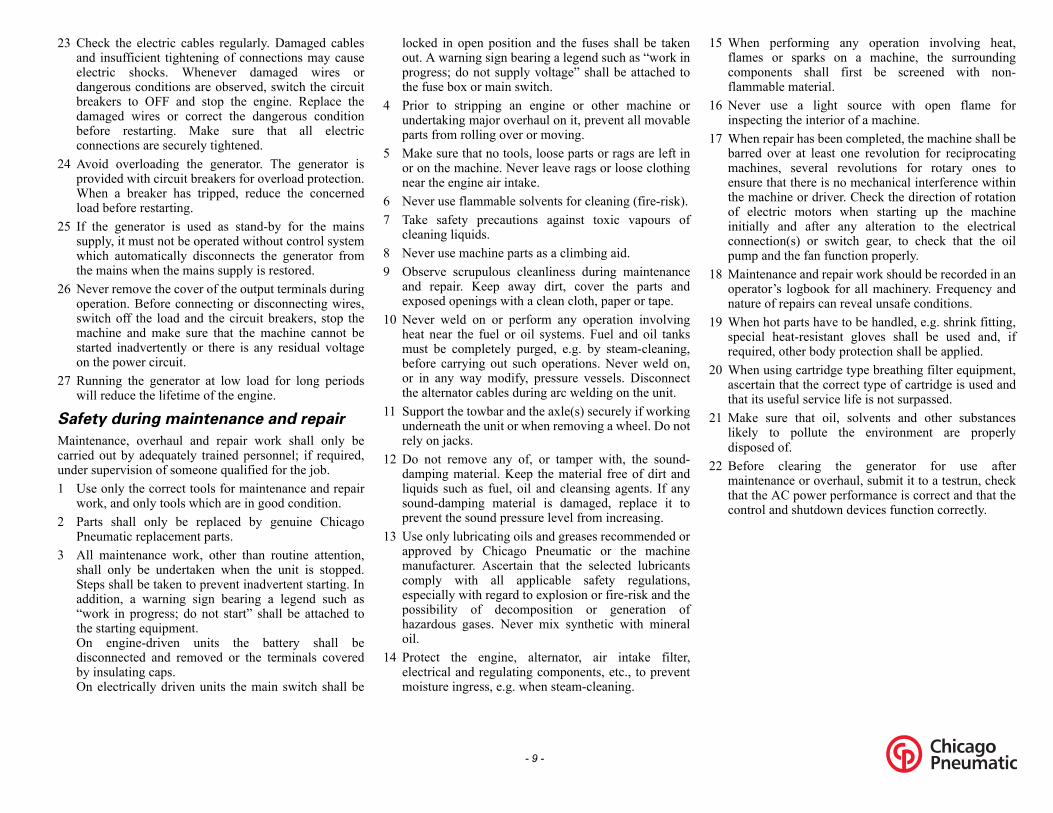
When performing any operation involving heat,flames or sparks on a machine, the surroundingcomponents shall first be screened with non-flammable material.Never use a light source with open flame forinspecting the interior of a machine.When repair has been completed, the machine shall bebarred over at least one revolution for reciprocatingmachines, several revolutions for rotary ones toensure that there is no mechanical interference withinthe machine or driver. Check the direction of rotationof electric motors when starting up the machineinitially and after any alteration to the electricalconnection(s) or switch gear, to check that the oilpump and the fan function properly.Maintenance and repair work should be recorded in anoperator’s logbook for all machinery. Frequency andnature of repairs can reveal unsafe conditions.When hot parts have to be handled, e.g. shrink fitting,special heat-resistant gloves shall be used and, ifrequired, other body protection shall be applied.When using cartridge type breathing filter equipment,ascertain that the correct type of cartridge is used andthat its useful service life is not surpassed.Make sure that oil, solvents and other substanceslikely to pollute the environment are properlydisposed of.Before clearing the generator for use aftermaintenance or overhaul, submit it to a testrun, checkthat the AC power performance is correct and that thecontrol and shutdown devices function correctly.
- 9 -
23 Check the electric cables regularly. Damaged cablesand insufficient tightening of connections may causeelectric shocks. Whenever damaged wires ordangerous conditions are observed, switch the circuitbreakers to OFF and stop the engine. Replace thedamaged wires or correct the dangerous conditionbefore restarting. Make sure that all electricconnections are securely tightened.
24 Avoid overloading the generator. The generator isprovided with circuit breakers for overload protection.When a breaker has tripped, reduce the concernedload before restarting.
25 If the generator is used as stand-by for the mainssupply, it must not be operated without control systemwhich automatically disconnects the generator fromthe mains when the mains supply is restored.
26 Never remove the cover of the output terminals duringoperation. Before connecting or disconnecting wires,switch off the load and the circuit breakers, stop themachine and make sure that the machine cannot bestarted inadvertently or there is any residual voltageon the power circuit.
27 Running the generator at low load for long periodswill reduce the lifetime of the engine.
Safety during maintenance and repair
Maintenance, overhaul and repair work shall only becarried out by adequately trained personnel; if required,under supervision of someone qualified for the job.1 Use only the correct tools for maintenance and repair
work, and only tools which are in good condition.2 Parts shall only be replaced by genuine Chicago
Pneumatic replacement parts.3 All maintenance work, other than routine attention,
shall only be undertaken when the unit is stopped.Steps shall be taken to prevent inadvertent starting. Inaddition, a warning sign bearing a legend such as“work in progress; do not start” shall be attached tothe starting equipment. On engine-driven units the battery shall bedisconnected and removed or the terminals coveredby insulating caps. On electrically driven units the main switch shall be
locked in open position and the fuses shall be takenout. A warning sign bearing a legend such as “work inprogress; do not supply voltage” shall be attached tothe fuse box or main switch.
4 Prior to stripping an engine or other machine orundertaking major overhaul on it, prevent all movableparts from rolling over or moving.
5 Make sure that no tools, loose parts or rags are left inor on the machine. Never leave rags or loose clothingnear the engine air intake.
6 Never use flammable solvents for cleaning (fire-risk).7 Take safety precautions against toxic vapours of
cleaning liquids.8 Never use machine parts as a climbing aid.9 Observe scrupulous cleanliness during maintenance
and repair. Keep away dirt, cover the parts andexposed openings with a clean cloth, paper or tape.
10 Never weld on or perform any operation involvingheat near the fuel or oil systems. Fuel and oil tanksmust be completely purged, e.g. by steam-cleaning,before carrying out such operations. Never weld on,or in any way modify, pressure vessels. Disconnectthe alternator cables during arc welding on the unit.
11 Support the towbar and the axle(s) securely if workingunderneath the unit or when removing a wheel. Do notrely on jacks.
12 Do not remove any of, or tamper with, the sound-damping material. Keep the material free of dirt andliquids such as fuel, oil and cleansing agents. If anysound-damping material is damaged, replace it toprevent the sound pressure level from increasing.
13 Use only lubricating oils and greases recommended orapproved by Chicago Pneumatic or the machinemanufacturer. Ascertain that the selected lubricantscomply with all applicable safety regulations,especially with regard to explosion or fire-risk and thepossibility of decomposition or generation ofhazardous gases. Never mix synthetic with mineraloil.
14 Protect the engine, alternator, air intake filter,electrical and regulating components, etc., to preventmoisture ingress, e.g. when steam-cleaning.
15
16
17
18
19
20
21
22

- 10 -
Tool applications safety
Apply the proper tool for each job. With the knowledgeof correct tool use and knowing the limitations of tools,along with some common sense, many accidents can beprevented.Special service tools are available for specific jobs andshould be used when recommended. The use of thesetools will save time and prevent damage to parts.
Battery safety precautions
BatteriesWhen servicing batteries, always wear protectingclothing and glasses.1 The electrolyte in batteries is a sulphuric acid solution
which is fatal if it hits your eyes, and which can causeburns if it contacts your skin. Therefore, be carefulwhen handling batteries, e.g. when checking thecharge condition.
2 Install a sign prohibiting fire, open flame and smokingat the post where batteries are being charged.
3 When batteries are being charged, an explosive gasmixture forms in the cells and might escape throughthe vent holes in the plugs.Thus an explosive atmosphere may form around thebattery if ventilation is poor, and can remain in andaround the battery for several hours after it has beencharged. Therefore:- never smoke near batteries being, or having recently
been, charged,- never break live circuits at battery terminals, because a
spark usually occurs.4 When connecting an auxiliary battery (AB) in parallel
to the unit battery (CB) with booster cables: connectthe + pole of AB to the + pole of CB, then connect the- pole of CB to the mass of the unit. Disconnect in thereverse order.

s stand-by in cases of interruption of the mains.- 1 phase. The CPG 70-90-120 John Deerehe diagram below.
1 Lifting beam2 Guiding rod3 Side doors4 Engine exhaust5 Data Plate6 Side door, access to control and indicator panel7 Output terminal board8 Hole for forkliftA AlternatorF Air filter
C CouplingH Drain and access hole (in the frame)
CW Drain Cooling WaterE EngineF FanCF Filler cap fuelCO Filler cap engine oil
W Filler cap cooling waterF Fuel filterR Frame1 BatteryD Oil DrainF Oil filter
LD Engine oil level dipstickW Selector Switch
- 11 -
Leading particulars
General description
The CPG 70-90-120 John Deere is an AC generator, built for continuous running at sites where no electricity is available or aThe generator can run in 3 different modes: 60 Hz, 480 V - 3 phase, 60 Hz, 208 V - 3 phase lower voltage and 60 Hz, 240 V generator is driven by a water-cooled diesel engine, manufactured by John Deere. An overview of the main parts is given in t
A
DD
FEFC
FFGOO
OS
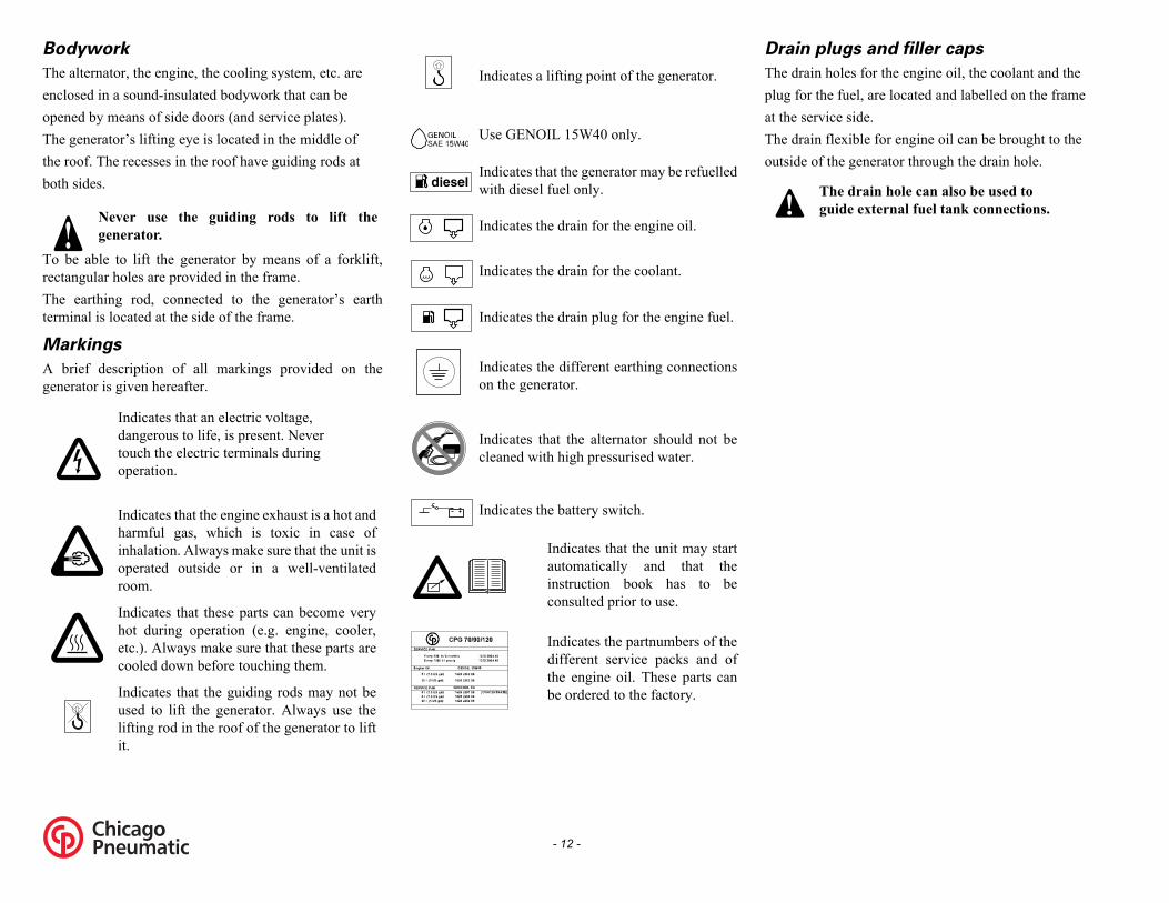
in plugs and filler caps
drain holes for the engine oil, the coolant and the for the fuel, are located and labelled on the framee service side.drain flexible for engine oil can be brought to thede of the generator through the drain hole.
The drain hole can also be used toguide external fuel tank connections.
- 12 -
Bodywork
The alternator, the engine, the cooling system, etc. areenclosed in a sound-insulated bodywork that can beopened by means of side doors (and service plates).The generator’s lifting eye is located in the middle ofthe roof. The recesses in the roof have guiding rods atboth sides.
To be able to lift the generator by means of a forklift,rectangular holes are provided in the frame.The earthing rod, connected to the generator’s earthterminal is located at the side of the frame.
Markings
A brief description of all markings provided on thegenerator is given hereafter.
Dra
The plugat thThe outsi
Never use the guiding rods to lift thegenerator.
Indicates that an electric voltage,dangerous to life, is present. Nevertouch the electric terminals duringoperation.
Indicates that the engine exhaust is a hot andharmful gas, which is toxic in case ofinhalation. Always make sure that the unit isoperated outside or in a well-ventilatedroom.
Indicates that these parts can become veryhot during operation (e.g. engine, cooler,etc.). Always make sure that these parts arecooled down before touching them.
Indicates that the guiding rods may not beused to lift the generator. Always use thelifting rod in the roof of the generator to liftit.
Indicates a lifting point of the generator.
Use GENOIL 15W40 only.
Indicates that the generator may be refuelledwith diesel fuel only.
Indicates the drain for the engine oil.
Indicates the drain for the coolant.
Indicates the drain plug for the engine fuel.
Indicates the different earthing connectionson the generator.
Indicates that the alternator should not becleaned with high pressurised water.
Indicates the battery switch.
Indicates that the unit may startautomatically and that theinstruction book has to beconsulted prior to use.
Indicates the partnumbers of thedifferent service packs and ofthe engine oil. These parts canbe ordered to the factory.
diesel
!

DOWN: Is used to scroll through thedisplay information and to adjustparameter value downwards.
BACK: Is used to leave the Alarm pop-upwindow, to leave the Parameter list and toleave menu's without change
REMOTE MODE: Is used toactivate the remote mode. The LEDindicates if the gen-set is put inRemote Mode.
START: Is used to start the unit inManual Mode.
STOP: Is used to stop the unit inManual or Remote Mode (withoutcooldown). When the unit is stoppedwith the STOP button in Remotemode, it will automatically go toManual Mode.
- 13 -
Control and indicator panel Qc1002™
General description Qc1002™ control panel
A1 .... Qc1002™ display
F10 ... Fuse
The fuse activates when the current from thebattery to the engine control circuit exceeds itssetting. The fuse can be reset by pushing the button.
H0 .... Panel light
S2........Emergency stop button
Push the button to stop the generator in caseof an emergency. When the button ispressed, it must be unlocked, before thegenerator can be restarted. The emergencystop button can be secured in the lockedposition with the key, to avoid unauthorizeduse.
S20 .. ON/OFF/REMOTE switch
Position O: No voltage is applied to theQc1002™ module, the generator will notstart.Position I: Voltage is applied to theQc1002™ module, it is possible to start upthe generator.
X25 .. Terminal strip
Qc1002™ Module
The Qc1002™ module is located inside the control panel.This control module will carry out all necessary tasks tocontrol and protect a generator, regardless of the use of thegenerator.This means that the Qc1002™ module can be used forseveral applications.Pushbutton and LED functions
Following pushbuttons are used on the Qc1002™
ENTER: Is used to select and confirmchanged settings in the Parameter list.
UP: Is used to scroll through the displayinformation and to adjust parameter valueupwards.

troller type and version display
view shows the controller type and the ASW versionber.
meter display
view shows a number of Parameter settings and givesss to them.verview is given in “Parameter list” on page 15.
m list display
view shows the number of active alarms and givesss to them.overview is given in “Alarm Display (pop-upow)” on page 17.
list display
view shows the alarm memory and gives access to it.verview is given in “LOG list” on page 18.
Qc1002v1.00.0
Parameter
Alarm List0 Alarm(s)
LOG List
- 14 -
Following LEDs are used on the Qc1002™ Qc1002™ Menu OverviewAt Qc1002™, the LCD will show following information:– in Normal condition (scroll through the information using
UP and DOWN):• Status (eg: preheat, crank, cooldown, extended stop time,
…) (pop-up: this display is only shown when a Specialstatus comes up)
• Controller type & version• Parameter list• Alarm list• LOG list• Service Timer 1 & Service Timer 2• Battery Voltage• Coolant temperature• Oil pressure• RPM (speed)• Fuel level• Voltage - frequency - running hours
– in Alarm condition (scroll through the information usingUP and DOWN):• a list of all active Alarms
It's possible to scroll through the views, using the UP andDOWN buttons. The scrolling is continuous. If a Special status comes up, the Status Display is shown. If an Alarm comes up, the Alarm Display is shown.
Con
Thisnum
Para
ThisacceAn o
Alar
ThisacceAn wind
LOG
ThisAn o
Power Green LED indicates that the unit is powered up.
Remote Green LED indicates that the Remote Mode is selected.
Start/Stop Green LED indicates that the engine isrunning.
Alarm Flashing red LED indicates that an alarm is present. A continuous red LED indicates that the alarm has been acknowledged by the user. The exact alarm is shown on the display.
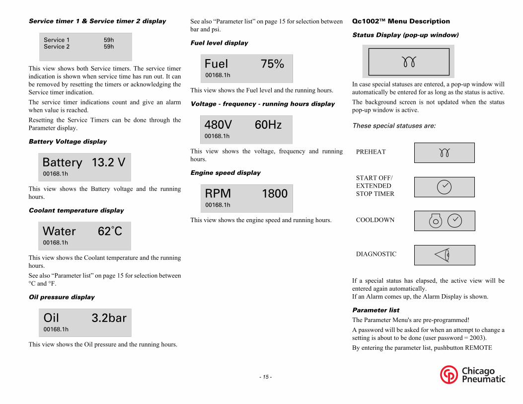
1002™ Menu Description
atus Display (pop-up window)
case special statuses are entered, a pop-up window willtomatically be entered for as long as the status is active.e background screen is not updated when the statusp-up window is active.
ese special statuses are:
a special status has elapsed, the active view will betered again automatically.an Alarm comes up, the Alarm Display is shown.
rameter list
e Parameter Menu's are pre-programmed!password will be asked for when an attempt to change ating is about to be done (user password = 2003). entering the parameter list, pushbutton REMOTE
REHEAT
TART OFF/XTENDED TOP TIMER
OOLDOWN
IAGNOSTIC
- 15 -
Service timer 1 & Service timer 2 display
This view shows both Service timers. The service timerindication is shown when service time has run out. It canbe removed by resetting the timers or acknowledging theService timer indication.The service timer indications count and give an alarmwhen value is reached.Resetting the Service Timers can be done through theParameter display.
Battery Voltage display
This view shows the Battery voltage and the runninghours.
Coolant temperature display
This view shows the Coolant temperature and the runninghours.See also “Parameter list” on page 15 for selection between°C and °F.
Oil pressure display
This view shows the Oil pressure and the running hours.
See also “Parameter list” on page 15 for selection betweenbar and psi.
Fuel level display
This view shows the Fuel level and the running hours.
Voltage - frequency - running hours display
This view shows the voltage, frequency and runninghours.
Engine speed display
This view shows the engine speed and running hours.
Qc
St
In auThpo
Th
If enIf
Pa
ThA setBy
Service 1Service 2
59h59h
13.2 VBattery00168.1h
62˚CWater00168.1h
3.2barOil00168.1h
75%Fuel00168.1h
60Hz480V00168.1h
1800RPM00168.1h
P
SES
C
D

enerator Undervoltage: failclass, enable, delay, setpointenerator Overvoltage: failclass, enable, delay, setpointngine CAN communicationis menu is used to select the type of engine electronics, the
c1002™ controller should communicate with via theanbus.ossible to scroll between configuration menu's by the pushbuttons UP and DOWN.ing the ENTER button activates the configurationu which is shown at the display.
- 16 -
is disposed of its normal operations and will notperform any functionality.Menu's shown on the Parameter list LCD:– Running hours adjust
This menu is used to adjust the amount of running hours. Therunning hours can only be raised, not lowered.
– Unit Type
– Service Timer 2 reset
– Service Timer 1 resetThese menus are used to reset the service timers. When aservice timer alarm occurs and is acknowledged, the servicetimer will be reset automatically.
– Diagnostics MenuThis menu is used to power up the engine electronics withoutstarting the engine. When this setting is switched ‘on’,electric power will be supplied to the engine electronics afterhalf a minute delay. The unit can not be started as long as thisparameter is switched ‘on’.
– Unit MenuThis menu is used to select whether tempreature and pressureshould appear in °C/bar or °F/psi.
– Language selectionIcons is the default factory set language, but 6 other languagescan be selected: English, French, German, Italian, Spanishand Cyrillic (Russian). All information in the Parameter Listdisplay is always in English.
– Generator Underfrequency: failclass, enable, delay,setpoint
– Generator Overfrequency: failclass, enable, delay,setpoint
– G– G– E
ThQC
It's pusingPushmen
Unit type 6 for CPG 70-90-120 John Deere!!
Qc1002 CAN145
Parameter Running time
Unit type
Unit type
Qc1002 CAN145
This is the described menu flow for changing the unit type:
ARORWalsh
Highlight

ERVICE TIMER 1
ERVICE TIMER 2
NGINE ALARM
MERGENCY TOP
TART FAILURE
TOP FAILURE
- 17 -
Alarm Display (pop-up window)
In case an Alarm occurs, a pop-up window willautomatically be displayed for as long as the alarm isactive, no matter which view is active. The flashing redalarm LED will light up. The alarm icons will be showntogether with an acknowledgement check-box. Push theENTER button to acknowledge the alarm. When the alarmhas been acknowledged, a V-marking will appear in thecheck-box and the red alarm LED will light upcontinuously.
The Alarm Display can always be left by pushing theBACK button.If more than one alarm comes up, it's possible to scrollthrough the alarm messages with the UP and DOWNpushbuttons. The newest alarm will be placed at thebottom of the list (meaning that the older alarm stays at thedisplay when a newer alarm comes up).If one or more than one alarm is present, an arrow at theright of the display will be shown.
Following general groups of Alarms exist:– Warning: Alarm LED lights up + Alarm pop-up appears
on the display + Alarm relay is empowered (if configured)– Trip of GB: ‘Warning’ actions + Generator Contactor
opens– Trip and Stop: ‘Trip of GB’ actions + unit stops after
Cooldown– Shutdown: ‘Trip of GB’ actions + unit stops immediately
List of possible alarms:
An alarm should always be acknowledgedbefore solving the problem that causes thealarm.
!
LOW OIL PRESSURE
HIGH COOLANT TEMPERATURE
CHARGING ALTERNATOR
LOW FUEL LEVEL
LOW COOLANT LEVEL
GENERATOR OVERVOLTAGE
GENERATOR UNDER-VOLTAGE
GENERATOR OVER-FREQUENCY
GENERATOR UNDER-FREQUENCY
S
S
E
ES
S
S

- 18 -
LOG list
The unit will keep an event log of the latest 30 events.Events are:– shutdowns– service timer 1/2 reset– unit type changesTogether with each event, the running hours at the time ofthe event will be stored.
Remort Start operation
Installation wirings:– X25.1 & X25.2 to be wired for the remote start switch.– X25.3 & X25.4 to be wired for the remote contactor (open/
close).
Fail classesAll the activated alarms of the Qc1002™ have their ownpre-defined fail class.All alarms are enabled according to one of these threestatuses:– disabled alarm, no supervision of alarm (OFF).– enabled alarm, supervision of alarm all the time (ON).
– running alarm, only supervision when the machine isrunning (RUN).
1 Controller type2 Event number3 Event4 Running hours
Time: 00001h
EVENT LOG #04 WaterQc1002
1
3
4
2

Circuit breakers Q1.1 do not only interruptthe power supply towards socket X1 butalso towards X2, X3, X4 and X5.Make sure to switch on circuit breakersQ1.1, Q2, Q3, Q4 and Q5 after starting thegenerator when power supply is done bymeans of X2, X3, X4 or X5.
- 19 -
Output terminal board
The output terminal board is situated below the controland indicator panel.
S2..... Emergency stop button
X1 .... Terminal board
Provides a more easy connection of cables.
X2 .... Single phase outlet socket (240V) Socket rated to 50A.
Provides L1,L2, neutral and earthing.
X3 .... Single phase outlet socket (240V) Socket rated to 50A.
Provides L1,L2, neutral and earthing.
X4 .... Single phase GFCI outlet socket (120V). Socket rated to 20A.
X5 .... Single phase GFCI outlet socket (120V). Socket rated to 20A.
Q1.1 . Circuit breaker for low voltage, high current
Interrupts the low voltage power supply towardsX1 when a short-circuit occurs at the load side orwhen the overcurrent protection (364 A) isactivated. It must be reset manually aftereliminating the problem.
Q1.2 . Circuit breaker for high voltage, low current
Interrupts the high voltage power supply towardsX1 when a short-circuit occurs at the load side orwhen the overcurrent protection (172 A) isactivated. It must be reset manually aftereliminating the problem.
Q2.... Circuit breaker for X2
Interrupts the power supply to X2 when a short-circuit occurs at the load side, or when theovercurrent protection (50 A) is activated. Whenactivated, Q2 interrupts one phase towards X2. Itcan be activated again after eliminating theproblem.
Q3.... Circuit breaker for X3
Interrupts the power supply to X3 when a short-circuit occurs at the load side, or when theovercurrent protection (50 A) is activated. Whenactivated, Q3 interrupts 2 phases towards X3. It canbe activated again after eliminating the problem.
Q4.... Circuit breaker for X4
Interrupts the power supply to X4 when a short-circuit occurs at the load side, or when theovercurrent protection (20 A) is activated. Whenactivated, Q4 interrupts 2 phases towards X4. It canbe activated again after eliminating the problem.
Q5.... Circuit breaker for X5
Interrupts the power supply to X5 when a short-circuit occurs at the load side, or when theovercurrent protection (20 A) is activated. Whenactivated, Q5 interrupts 2 phases towards X5. It canbe activated again after eliminating the problem.

llage free skid
illage free skid with forklift slots allows the customernsport the generator easily with a forklift.
oids accidental spilling of engine fluids.
- 20 -
Triple voltage (3V)
The generator can run in three different modes:– 1 phase
When using this selection, the generator provides a 240/277V output voltage.
– 3 phase, lower voltage
When using this selection, the generator provides a 208/240V output voltage.
– 3 phase, higher voltage
When using this selection, the generator provides a 416/480V output voltage.
Q1.1 . Circuit breaker for low voltage, high current
Interrupts the low voltage power supply towardsX1 when a short-circuit occurs at the load side orwhen the overcurrent protection is activated. Itmust be reset manually after eliminating theproblem.
Q1.2 . Circuit breaker for high voltage, low current
Interrupts the high voltage power supply towardsX1 when a short-circuit occurs at the load side orwhen the overcurrent protection is activated. Itmust be reset manually after eliminating theproblem.
R12... Output voltage adjust potentiometer
Allows to adjust the output voltage.Depending on which mode the generator is running in,circuit breaker Q1.1 or Q1.2 will be operational.Circuit breakers Q1.1 and Q1.2 cannot be switched on atthe same time. This is prevented by means of the auxiliaryvoltage selection relays S10b and S10c (refer to the circuitdiagram).The selection between the three voltage modes isperformed by means of S10.
S10... Output voltage selection switch
Allows to select a 1 phase output voltage, a 3 phasehigh output voltage or a 3 phase low outputvoltage. Selector switch S10 is located on thealternator.
Spi
A spto traIt av
Changing the output voltage is only allowedafter shutdown.After changing the output voltage by meansof the selection switch S10, adjust the outputvoltage by means of potentiometer R12 to therequired value.

ain applicable if they are stricter than those proposedlow.
e lowest acceptable wire section and the correspondingximum cable or conductor length for multiple corele or H07 RN-F, at rated current, for a voltage drop eer than 5% and at a power factor of 0.80, are
pectively 10 mm² (0.39 in²) and 146 m (179 ft). In casectric motors must be started, oversizing the cable isvisable.e voltage drop across a cable can be determined aslows:
Voltage drop (V) Rated current (A) Length of conductors (m)
= Resistance (/km to VDE 0102)= Reactance (/km to VDE 0102)
nnecting the load
te distribution panel
outlet sockets are required, they must be mounted on ae distribution panel supplied from the terminal board of generator and in compliance with local regulations forwer installations on building sites.
Wire section Max. current (A) (mm²) Multiple core Single core H07 RN-F
25 94 101 8835 114 123 11050 138 155 13870 176 191 17095 212 228 205120 245 273 239150 282 314 275185 323 358 313240 379 421 371300 429 477 428
e 3 I L R cos X sin+ 1000
------------------------------------------------------------------------------=
- 21 -
Operating instructions
Installation
– Place the generator on a horizontal, even and solid floor.The generator can operate in a slant position not exceeding15° (in both senses: front/rear and left/right).
– The generator should be kept with the doors closed, inorder to avoid the ingress of water and dust. Dust ingressreduces the lifetime of filters and may reduce yourgenerator's performance.
– Check that the engine exhaust is not directed towardspeople. If the generator is operated indoors, install anexhaust pipe of sufficient diameter to duct the engineexhaust towards the outside. Check for sufficientventilation so that the cooling air is not recirculated. Ifnecessary, consult Chicago Pneumatic.
– Leave enough space for operation, inspection andmaintenance (at least 1 meter at each side).
– Check that the inner earthing system is in compliance withthe local legislation.
– Use coolant for the engine cooling system. Refer to theEngine instruction book for the proper coolant mixture.
– Check the tightness of the bolts and nuts.– Install the earthing rod as near as possible to the generator
and measure its diffusion resistance (max. 1 k) in ordernot to have a contact voltage higher than 25 V at 30 mAleakage current.
– Check that the cable end of the earthing rod is connectedto the earth terminal.
Connecting the generator
Precautions for non-linear and sensitive loads
The most common non-linear, 3-phase loads are thyristor/rectifier-controlled loads, such as convertors supplyingvoltage to variable speed motors, uninterruptable powersupplies and Telecom supplies. Gas-discharge lightingarranged in single-phase circuits generate high 3rdharmonics and risk for excessive neutral current.Loads most sensitive to voltage distortion includeincandescent lamps, discharge lamps, computers, X-rayequipment, audio amplifiers and elevators.Consult Chicago Pneumatic for measures against theadverse influence of non-linear loads.
Quality, minimum section and maximum length of cablesThe cable connected to the terminal board of the generatormust be selected in accordance with local legislation. Thetype of cable, its rated voltage and current carryingcapacity are determined by installation conditions, stressand ambient temperature. For flexible wiring, rubber-sheathed, flexible core conductors of the type H07 RN-F(Cenelec HD.22) or better must be used.The following table indicates the maximum allowable 3-phase currents (in A), in an ambient temperature of 40°C(104°F), for cable types (multiple and single core PVCinsulated conductors and H07 RN-F multiple coreconductors) and wire sections as listed, in accordance withVDE 0298 installation method C3. Local regulations
rembe
ThmacablowreseleadThfol
e =I =L =R X
Co
Si
If sitthepo
In your own interest, always strictly observeall relevant safety instructions.Do not operate the generator in excess of thelimitations mentioned in the TechnicalSpecifications.Local rules concerning the setting up of lowvoltage power installations (below 1000 V)must be respected when connecting sitedistribution panels, switch gear or loads tothe generator.
For information about indoor installation,consult your local Chicago Pneumatic dealer.
Non-linear loads draw currents with highcontents in harmonics, causing distortion inthe wave form of the voltage generated bythe alternator.

rating Qc1002™
rting Qc1002™
tart up the unit locally, proceed as ws:itch on the battery switch.itch off circuit breaker Q1.1/Q1.2 . This is not
cessary when a plant contactor is installed between1.1/Q1.2 and the load.t switch S20 in position I (ON). Voltage is applied to the
c1002™ module.he unit can be started manually by pressing the STARTtton on the Qc1002™ module.
he unit starts a preheating cycle which takes 12 seconds.fter the preheating period, the unit will start. The startingtempt will take maximum 12 seconds.
itch on circuit breaker Q1.1/Q1.2 in case no contactor installed.
tart up the unit from a remote location, eed as follows:t the starter switch S20 in position I (ON). Voltage isplied to the Qc1002™ module.
he unit can be started from a remote location by pressinge remote mode button on the Qc1002™ module.
itch on circuit breaker Q1.1/Q1.2 .t the remote start/stop switch in position start.
he unit starts a preheating cycle which takes 12 seconds.fter the preheating period, the unit will start. The startingtempt will take maximum 12 seconds.
- 22 -
Protection
– Check whether frequency, voltage and current complywith the ratings of the generator.
– Provide for the load cable, without excessive length, andlay it out in a safe way without forming coils.
– Open the door of the control and indicator panel and thetransparent door in front of the terminal board X1.
– Provide the wire ends with cable lugs suited for the cableterminals.
– Loosen the cable clamp and push the wire ends of the loadcable through the orifice and clamp.
– Connect the wires to the proper terminals (L1, L2, L3, Nand PE) of X1 and tighten the bolts securely.
– Tighten the cable clamp.– Close the transparent door in front of X1.
Before starting
– With the generator standing level, check the engine oillevel and top up if necessary. The oil level must be near to,but not exceed the high mark on the engine oil leveldipstick.
– Check the coolant level in the expansion tank of the enginecooling system. The coolant level must be near to theFULL mark. Add coolant if necessary.
– Drain any coolant and sediment from the fuel pre-filter.Check the fuel level and top up if necessary. It isrecommended to fill the tank after the day’s operation toprevent coolantdamp in a nearly empty tank fromcondensing.
– Check the vacuum indicator of the air filter. If the red partshows completely, replace the filter element.
– Press the vacuator valve of the air filter to remove dust.– Check the generator for leakage, tightness of wire
terminals, etc. Correct if necessary. – Check that fuse F10 has not tripped and that the
emergency stop is in the OUT position.– Check that the load is switched off.– Check that circuit breaker Q1.1/Q1.2 are switched off.
Ope
Sta
To sfollo– Sw– Sw
neQ
– PuQ
– Tbu
– T– A
at– Sw
is
To sproc– Pu
ap– T
th– Sw– Pu– T– A
at
For safety reasons, it is necessary to providean isolating switch or circuit breaker in eachload circuit. Local legislation may impose theuse of isolating devices which can be locked.
!

- 23 -
During operation Qc1002™Following points should be carried out regularly:– Check the engine gauges and the lamps for normal
readings.
– Check for leakage of oil, fuel or coolant.– Avoid long low-load periods (< 30%). In this case, an
output drop and higher oil consumption of the enginecould occur.
– Check, by means of the generator gauges, that the voltagebetween the phases is identical and that the rated current inthe third phase (L3) is not exceeded.
– When single-phase loads are connected to the generatoroutput terminals, keep all loads well-balanced.
If circuit breakers are activated during operation, switchoff the load and stop the generator. Check and, ifnecessary, decrease the load.
Stopping Qc1002™
To stop the unit locally, proceed as follows:– Switch off the load.– Switch off circuit breaker Q1.1/Q1.2 .– Let the engine run for about 5 minutes.– Stop the engine by using the STOP button on the
Qc1002™ module.– Put switch S20 in position O (OFF) to shut down the
voltage apply towards the Qc1002™ module.– Lock the side doors and the door of the indicators and
control panel to avoid unauthorized access.
To stop the unit when the Qc1002™ module is in position , proceed as follows:– Switch off the load.
– Stop the engine by putting the remote start/stop switch inposition stop or by using the STOP button on theQc1002™ module. When the unit is stopped with theSTOP button in Remote mode, it will automatically go toManual Mode.
– Put the starter switch S20 in position O (OFF) to shutdown the voltage apply towards the Qc1002™ module.
– Lock the side doors and the door of the indicators andcontrol panel to avoid unauthorized access.
Avoid to let the engine run out of fuel. If ithappened, priming will speed up thestarting.
The generator’s doors may only remainopened for short periods during operation,to carry out checks for example.
!
!

power is present on the terminals.
ry 250 hours or 6 nths
Every 1000 hours or yearly
0 3004 45 1310 3004 46
ou the benefits of genuine parts, save on administration service kits.
x x
x x
x x
x x
x x
x x
x
x
x x
x
x
x
x
x
x
x
x
x
x
x
x
x
- 24 -
Maintenance
Maintenance schedule
Before carrying out any maintenance activity, check that the start switch is in position O and that no electrical !
Maintenance schedule DailyEvemo
Service pak - 131
For the most important subassemblies, Chicago Pneumatic has developed service kits that combine all wear parts. These service kits offer ycosts and are offered at reduced price, compared to the loose components. Refer to the parts list for more information on the contents of the
Check for air, fuel, coolant and oil leakage x
Check oil and coolant level x
Check or drain water in fuelfilter/waterseparator x
Inspect air cleaner / Dust bowl x
Check vaccuum imdicator x
Visual walk around the unit x
Replace engine oil (2) (4)
Replace engine oil filter (2) (4)
Check/clean radiator/cooler fins
Check tension and condition of the drive belt (4)
Grease door hinges and locks
Replace fuel filter element (2) (3)
Replace fuel prefilter element (2) (3)
Check electrolyte level and terminals of battery
Check engine mounts
Check crankcase ventilation system
Check condition of cooling fan assembly
Pressure test cooling system
Check engine electrical ground connection
Replace air filter element (1)
Replace safety cartridge (1)
Measure alternator insulation resistance (*)
(To be continued on page 25)
very 250 hours or 6 onths
Every 1000 hours or yearly
310 3004 45 1310 3004 46
x
x
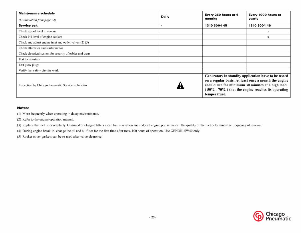
enerators in standby application have to be testedn a regular basis. At least once a month the enginehould run for minimum 30 minutes at a high load 50% - 70% ) that the engine reaches its operatingemperature.
uel determines the frequenay of renewal.
- 25 -
Maintenance schedule
(Continuation from page 24)Daily
Em
Service pak - 1
Check glycol level in coolant
Check PH level of engine coolant
Check and adjust engine inlet and outlet valves (2) (5)
Check alternator and starter motor
Check electrical system for security of cables and wear
Test thermostats
Test glow plugs
Verify that safety circuits work
Inspection by Chicago Pneumatic Service technician
Gos(t
Notes:
(1) More frequently when operating in dusty environments.
(2) Refer to the engine operation manual.
(3) Replace the fuel filter regularly. Gummed or clogged filters mean fuel starvation and reduced engine perfacmance. The quality of the f
(4) During engine break-in, change the oil and oil filter for the first time after max. 100 hours of operation. Use GENOIL 5W40 only.
(5) Rocker cover gaskets can be re-used after valve clearence.

ine oil level check
ult the Engine Operation Manual for the oilifications, viscosity recommendations and oil changevals.intervals, see section “Maintenance schedule” on24.k engine oil level according to the instructions in thene Operation Manual and if necessary top up with oil.
ine oil and oil filter change
ection “Maintenance schedule” on page 24.
ine coolant specifications
use of the correct coolant is important for good heatfer and protection of liquid-cooled engines. Coolants in these engines must be mixtures of good qualityr (distilled or de-ionised), special coolant additivesif necessary freeze protection. Coolant that is not toufacturer's specification will result in mechanicalage of the engine.freezing point of the coolant must be lower than theing point that can occur in the area. The difference be at least 5°C (41°F). If the coolant freezes, it may the cylinder block, radiator or coolant pump.ult the engine's operation manual and follow the
ufacturer's directions.
Never remove the cooling system filler capwhile coolant is hot.The system may be under pressure. Removethe cap slowly and only when coolant is atambient temperature. A sudden release ofpressure from a heated cooling system canresult in personal injury from the splash ofhot coolant.It is strongly recommended to use ChicagoPneumatic branded coolant.
Never mix different coolants and mix thecoolant components outside the coolingsystem.
- 26 -
Engine maintenance
Refer to the engine’s operator manual for full maintenanceschedule.
(*) Measuring the alternator insulation
resistance
A 500 V megger is required to measure the alternatorinsulation resistance.If the N-terminal is connected to the earthing system, itmust be disconnected from the earth terminal. Disconnectthe AVR.Connect the megger between the earth terminal andterminal L1 and generate a voltage of 500 V. The scalemust indicate a resistance of at least 5 M.Refer to the alternator operating and maintenanceinstructions for more details.
Engine oil specifications
High-quality, mineral, hydraulic or synthesizedhydrocarbon oil with rust and oxidation inhibitors, anti-foam and anti-wear properties is recommended.The viscosity grade should correspond to the ambienttemperature and ISO 3448, as follows.
Specifications GENOILGENOIL from Atlas Copco is the ONLY oil tested andapproved for use in all engines built into Atlas Copcocompressors and generators.Extensive laboratory and field endurance tests on AtlasCopco equipment have proven GENOIL to match alllubrication demands in varied conditions. It meetsstringent quality control specifications to ensure yourequipment will run smoothly and reliably.
The quality lubricant additives in GENOIL allow forextended oil change intervals without any loss inperformance or longevity.GENOIL provides wear protection under extremeconditions. Powerful oxidation resistance, high chemicalstability and rust- inhibiting additives help reducecorrosion, even within engines left idle for extendedperiods.GENOIL contains high quality anti-oxidants to controldeposits, sludge and contaminants that tend to build upunder very high temperatures.GENOIL's detergent additives keep sludge formingparticles in a fine suspension instead of allowing them toclog your filter and accumulate in the valve/rocker coverarea.GENOIL releases excess heat efficiently, whilstmaintaining excellent bore-polish protection to limit oilconsumption.GENOIL has an excellent Total Base Number (TBN)retention and more alkalinity to control acid formation.GENOIL prevents Soot build-up.GENOIL is optimized for the latest low emission EURO -3 & -2, EPA TIER II & III engines running on low sulphurdiesel for lower oil and fuel consumption.
GENOIL 5W40GENOIL 5W40 is a Synthetic ultra high performancediesel engine oil with a high viscosity- index. Atlas CopcoGENOIL 5W40 is designed to provide excellentlubrication from start-up in temperatures as low as -25°C (-13°F).
Eng
ConsspecinterFor pageChecEngi
Eng
See s
Eng
The transusedwateand mandamThe freezmustcrackConsman
It is strongly recommended to use AtlasCopco branded lubrication oils.
Engine Type of lubricant
between -25°C (-13°F) and 40°C (104°F) GENOIL 5W40
Liter US gal
Imp gal cu.ft Order
number
can 5 1.3 1.1 0.175 1604 6060 01
barrel 210 55.2 46 7.35 1604 6059 01

- 27 -
Specifications GENCOOL EG GENCOOL EG is the only coolant that has been testedand approved by all engine manufacturers currently in usein Chicago Pneumatic compressors and generators.Chicago Pneumatic's GENCOOL EG extended lifecoolant is the new range of organic coolants purposedesigned to meet the needs of modern engines.GENCOOL EG can help prevent leaks caused bycorrosion. GENCOOL EG is also fully compatible with allsealants and gasket types developed to join differentmaterials used within an engine.GENCOOL EG is a ready to use Ethylene Glycol basedcoolant, premixed in an optimum 50/50 dilution ratio, forantifreeze protection guaranteed to -40°C (-40°F).Because GENCOOL EG inhibits corrosion, depositformation is minimized. This effectively eliminates theproblem of restricted flow through the engine coolantducts and the radiator, minimizing the risk for engineoverheating and possible failure.It reduces water pump seal wear and has excellent stabilitywhen subjected to sustained high operating temperatures.GENCOOL EG is free of nitride and amines to protectyour health and the environment. Longer service lifereduces the amount of coolant produced and needingdisposal to minimise environmental impact.
To ensure protection against corrosion, cavitation andformation of deposits, the concentration of the additives inthe coolant must be kept between certain limits, as statedby the manufacturer's guidelines. Topping up the coolantwith water only, changes the concentration and istherefore not allowed.
Liquid-cooled engines are factory-filled with this type ofcoolant mixture.
Liter US gal
Imp gal cu.ft Order
number
can 5 1.3 1.1 0.175 1604 5308 00
can 25 6.5 4.4 0.7 1604 5307 00
barrel 209 55 46 7.35 1604 5306 00

- 28 -
Coolant check
Monitoring coolant conditionIn order to guarantee the lifetime and quality of theproduct, thus to optimise engine protection, regularcoolant-condition-analysis is advisable.The quality of the product can be determined by threeparameters.
Visual check– Verify the outlook of the coolant regarding colour and
make sure that no loose particles are floating around.
pH measurement– Check the pH value of the coolant using a pH-measuring
device.– The pH-meter can be ordered from Chicago Pneumatic
with part number 2913 0029 00.– Typical value for EG = 8.6.– If the pH-level is below 7 or above 9.5, the coolant should
be replaced.
Glycol concentration measurement– To optimise the unique engine protection features of the
GENCOOL EG the concentration of the Glycol in thewater should be always above 33 vol.%.
– Mixtures with more than 68 vol.% mix ratio in water arenot recommended, as this will lead to high engineoperating temperatures.
– A refractometer can be ordered from Chicago Pneumaticwith part number 2913 0028 00.
Topping up of coolant– Verify if the engine cooling system is in a good condition
(no leaks, clean,...).– Check the condition of the coolant.
– If the condition of the coolant is outside the limits, thecomplete coolant should be replaced (see section“Replacing the coolant”).
– Always top-up with GENCOOL EG.– Topping up the coolant with water only, changes the
concentration of additives and is therefore not allowed.
Replacing the coolant
Drain– Completely drain the entire cooling system.– Used coolant must be disposed or recycled in accordance
with laws and local regulations.
Flush– Flush twice with clean water. Used coolant must be
disposed or recycled in accordance with laws and localregulations.
– From the Chicago Pneumatic Instruction book, determinethe amount of GENCOOL EG required and pour into theradiator top tank.
– It should be clearly understood that the risk forcontamination is reduced in case of proper cleaning.
– In case a certain content of ‘other’ coolant remains in thesystem, the coolant with the lowest properties influencesthe quality of the ‘mixed’ coolant.
Fill– To assure proper operation and the release of trapped air,
run the engine until normal engine operation temperatureis reached. Turn off the engine and allow to cool.
– Recheck coolant level and add if necessary.In case of a mix of different coolant productsthis type of measurement might provideincorrect values.
- 29 -
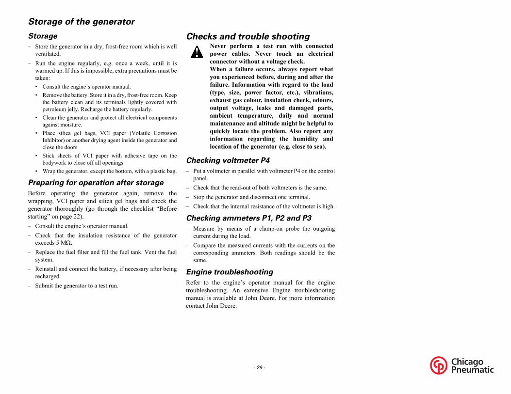
Storage of the generator
Storage
– Store the generator in a dry, frost-free room which is wellventilated.
– Run the engine regularly, e.g. once a week, until it iswarmed up. If this is impossible, extra precautions must betaken:• Consult the engine’s operator manual.• Remove the battery. Store it in a dry, frost-free room. Keep
the battery clean and its terminals lightly covered withpetroleum jelly. Recharge the battery regularly.
• Clean the generator and protect all electrical componentsagainst moisture.
• Place silica gel bags, VCI paper (Volatile CorrosionInhibitor) or another drying agent inside the generator andclose the doors.
• Stick sheets of VCI paper with adhesive tape on thebodywork to close off all openings.
• Wrap the generator, except the bottom, with a plastic bag.
Preparing for operation after storage
Before operating the generator again, remove thewrapping, VCI paper and silica gel bags and check thegenerator thoroughly (go through the checklist “Beforestarting” on page 22).– Consult the engine’s operator manual.– Check that the insulation resistance of the generator
exceeds 5 M.– Replace the fuel filter and fill the fuel tank. Vent the fuel
system.– Reinstall and connect the battery, if necessary after being
recharged.– Submit the generator to a test run.
Checks and trouble shooting
Checking voltmeter P4
– Put a voltmeter in parallel with voltmeter P4 on the controlpanel.
– Check that the read-out of both voltmeters is the same.– Stop the generator and disconnect one terminal.– Check that the internal resistance of the voltmeter is high.
Checking ammeters P1, P2 and P3
– Measure by means of a clamp-on probe the outgoingcurrent during the load.
– Compare the measured currents with the currents on thecorresponding ammeters. Both readings should be thesame.
Engine troubleshooting
Refer to the engine’s operator manual for the enginetroubleshooting. An extensive Engine troubleshootingmanual is available at John Deere. For more informationcontact John Deere.
Never perform a test run with connectedpower cables. Never touch an electricalconnector without a voltage check.When a failure occurs, always report whatyou experienced before, during and after thefailure. Information with regard to the load(type, size, power factor, etc.), vibrations,exhaust gas colour, insulation check, odours,output voltage, leaks and damaged parts,ambient temperature, daily and normalmaintenance and altitude might be helpful toquickly locate the problem. Also report anyinformation regarding the humidity andlocation of the generator (e.g. close to sea).
ying a 12V battery voltage with a 30 W resistor in series on lectronic regulator, respecting the polarities.asure winding resistances and compare with values anual.
ulator.
or lower than 0.8; speed lower than 10% of rated speed.
bles.
r by acting on STABILITY potentiometer.
- 30 -
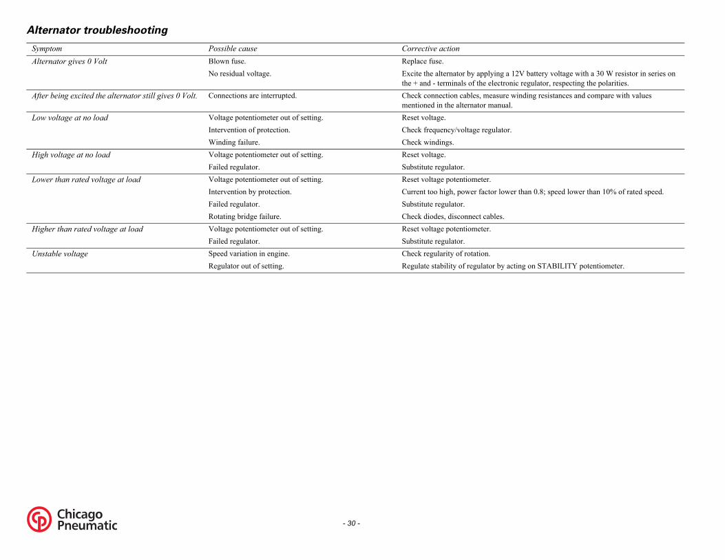
Alternator troubleshooting
Symptom Possible cause Corrective actionAlternator gives 0 Volt Blown fuse. Replace fuse.
No residual voltage. Excite the alternator by applthe + and - terminals of the e
After being excited the alternator still gives 0 Volt. Connections are interrupted. Check connection cables, mementioned in the alternator m
Low voltage at no load Voltage potentiometer out of setting. Reset voltage.Intervention of protection. Check frequency/voltage regWinding failure. Check windings.
High voltage at no load Voltage potentiometer out of setting. Reset voltage.Failed regulator. Substitute regulator.
Lower than rated voltage at load Voltage potentiometer out of setting. Reset voltage potentiometer.Intervention by protection. Current too high, power factFailed regulator. Substitute regulator.Rotating bridge failure. Check diodes, disconnect ca
Higher than rated voltage at load Voltage potentiometer out of setting. Reset voltage potentiometer.Failed regulator. Substitute regulator.
Unstable voltage Speed variation in engine. Check regularity of rotation.Regulator out of setting. Regulate stability of regulato

US Metric
0 Hz 60 Hz 0 rpm 1800 rpm
PRP PRP0 kPa 100 kPa0% 30%7°F 25°C
22°F 50°C,000 ft 4000 m5% 85%
0 °F -18 °C13°F -25°C
6 kW 56 kW.3 kW 43.3 kW0,80 0,801.0 1.0 kVA 70 kVA
.3 kVA 43.3 kVA80 V 480 V40 V 240 V40 V 240 V4 A 84 A
68 A 168 A80 A 180 AG2 G21 % <1 %
- 31 -
Technical specifications for CPG 70 John Deere
Readings on gauges
Settings of switches
Specifications of the engine/alternator/unit
Gauge Reading Unit
Ammeter L1-3 (P1-3) Below max. rating A
Voltmeter (P4) Depends upon selector switch V
Switch Function Activates at (US) Activates at (Metric)
Engine oil pressure Shut down 7.25 psi 0.5 barEngine coolant temperature Shut down 230°F 110°C
Reference conditions 1) Rated frequency 6Rated speed 180Generator service dutyAbsolute inlet pressure 10Relative air humidity 3Air inlet temperature 7
Limitations 2) Maximum ambient temperature 1Altitude capability 13Relative air humidity maximum 8Minimum starting temperature unaidedMinimum starting temperature aided -
Performance data 2) 3) 5) Rated active power (PRP) 3 php 5Rated active power (PRP) 1ph 43Rated power factor (lagging) 3phaseRated power factor (lagging) 1phaseRated PRP power (PRP) 3ph 70Rated PRP power (PRP)1ph 43Rated voltage 3ph. line to line 4Rated voltage 3ph. line to line lower voltage 2Rated voltage 1ph. line to line 2Rated current 3ph 8Rated current 3ph lower voltage 1Rated current 1ph. 1Performance class (acc.ISO 8528-5:1993)Frequency droop <

S Metriconous isochronous lb/h 14.6/1.6 kg/h/kWh 0.262 kg/kWh
3 h 37.3 h
A N/A(A) 69 dB(A)S gal 660 l
% 100 %
P PRP use land usegle singlel/auto manual/autocified unspecifiedtable/D transportable/Dile/E mobile/Esilient fully resilient air open air
54 IP 54hed earthed
34-1 IEC 34-1528-3 ISO 8528-3
AGE NEWAGE24 G1 UCI 224 G1kVA 72.5 kVAR BR IP 23 IP
HH
2 12
3046 ISO 3046528-2 ISO 8528-2EERE JOHN DEERE5285 TF4045285hp 67 kWN ICXN
ter water
- 32 -
Uisochr
Fuel consumption at full load/no load 32/3.5Specific fuel consumption 0.58 lbFuel autonomy at full load with standard tank 37.Maximum sound power level (LWA)measured according to 2000/14/EC OND N/Sound Level @ 23 Feet @ 75% Load 69 dBCapacity of fuel tank 174.5 USingle step load acceptance 100
Application data Mode of operation PRSite landOperation sinStart-up and control mode manuaStart-up time unspeMobility/Config. acc. to ISO 8528-1:1993 transpor
mobMounting fully reClimatic exposure openDegree of protection (cubicle) IP Status of neutral eart
Design data 4)Alternator
Standard IEC ISO 8
Make NEWModel UCI 2Rated output, class H temp. rise 72.5 Rating type acc. ISO 8528-3 BDegree of protection 23Insulation class stator HInsulation class rotor HNumber of wires 1
Engine Standard ISO ISO 8
Make JOHN DModel TF404Rated net output 90 Rating type acc. ISO 3046-7 ICXCoolant wa
Technical specifications for CPG 70 John Deere

US Metric
ater water
injection direct injectionurbo turbo
4 4 US gal 4.5 lctronic electronic US gal 21 l US gal 16 l Vdc 12 Vdc
3 300 A 100 A.5xIn 3.5xIn
3 300 A 200 A.5xIn 3.5xIn
uplex (2x) GFCI duplex (2x)p + E 2p + E
125 V 20 A 125 V
ower (2x) Temp power (2x) N + E 2p + N + E
25/250 V 50 A 125/250 V
- 33 -
Coolant w
Combustion system directAspiration tNumber of cylindersSwept volume 1.19Speed governing eleCapacity of oil sump 5.5Capacity of cooling system 4.2Electrical system 12
Power circuit Circuit-breaker, 3 phaseNumber of poles Thermal release It 1Magnetic release Im 3Circuit-breaker, 3 phase, lower voltage (208 V)Number of polesThermal release It 2Magnetic release Im 3
Outlet sockets GFCI d2
20 A
Temp p2p +
50 A 1
Technical specifications for CPG 70 John Deere

S Metric
Hz 60 Hz rpm 1800 rpmP PRP
kPa 100 kPa% 30%°F 25°C
°F 50°C00 ft 4000 m% 85%°F -18 °C°F -25°C
kW 72 kWkW 60 kW80 0,80.0 1.0VA 90 kVAVA 60 kVA V 480 V V 208 V V 240 V A 108 A A 250 A A 250 A2 G2 % <1 %.9 lb/h 18.6/14 kg/h
- 34 -
Technical specifications for CPG 90 John Deere
Readings on gauges
Settings of switches
Specifications of the engine/alternator/unit
Gauge Reading UnitAmmeter L1-3 (P1-3) Below max. rating AVoltmeter (P4) Depends upon selector switch V
Switch Function Activates at (US) Activates at (Metric)Engine oil pressure Shut down 7.25 psi 0.5 barEngine coolant temperature Shut down 230°F 110°C
U
Reference conditions 1) Rated frequency 60 Rated speed 1800Generator service duty PRAbsolute inlet pressure 100Relative air humidity 30Air inlet temperature 77
Limitations 2) Maximum ambient temperature 122Altitude capability 13,0Relative air humidity maximum 85Minimum starting temperature unaided 0 Minimum starting temperature aided -13
Performance data 2) 3) 5) Rated active power (PRP) 3 php 72 Rated active power (PRP) 1ph 60 Rated power factor (lagging) 3phase 0,Rated power factor (lagging) 1phase 1Rated PRP power (PRP) 3ph 90 kRated PRP power (PRP)1ph 60 kRated voltage 3ph. line to line 480Rated voltage 3ph. line to line lower voltage 208Rated voltage 1ph. line to line 240Rated current 3ph 108Rated current 3ph lower voltage 250Rated current 1ph. 250Performance class (acc.ISO 8528-5:1993) GFrequency droop <1Fuel consumption at full load/no load 41/30

US Metric lb/kWh 0.258 kg/kWh5.8 h 25.8 h
dB(A) 69 dB(A) dB(A) 69 dB(A) US gal 605 l5 % 85 %
PRP PRPd use land use
ingle singleual/auto manual/autoecified unspecifiedortable/D transportable/Dbile/E mobile/E resilient fully resilienten air open airP 54 IP 54rthed earthed
C 34-1 IEC 34-1 8528-3 ISO 8528-3WAGE NEWAGE 224 G1 UCI 224 G1 kVA 90 kVABR BR3 IP 23 IPH HH H12 12 3046 ISO 3046
8528-2 ISO 8528-2 DEERE JOHN DEERE
26 hp 94 kWCXN ICXN
ater water injection direct injectionurbo turbo
4 4 US gal 4.5 l
- 35 -
Specific fuel consumption 0.57Fuel autonomy at full load with standard tank 2Maximum sound power level (LWA)measured according to 2000/14/EC OND 69Sound Level @ 23 Feet @ 75% Load 69Capacity of fuel tank 160Single step load acceptance 8
Application data Mode of operationSite lanOperation sStart-up and control mode manStart-up time unspMobility/Config. acc. to ISO 8528-1:1993 transp
moMounting fullyClimatic exposure opDegree of protection (cubicle) IStatus of neutral ea
Design data 4)Alternator
Standard IEISO
Make NEModel UCIRated output, class H temp. rise 90Rating type acc. ISO 8528-3Degree of protection 2Insulation class statorInsulation class rotorNumber of wires
Engine Standard ISOISO
Make JOHNRated net output 1Rating type acc. ISO 3046-7 ICoolant wCombustion system directAspiration tNumber of cylindersSwept volume 1.19
Technical specifications for CPG 90 John Deere

S Metricronic electronicS gal 8.5 lS gal 16 ldc 12 Vdc
35A 125 AxIn 3.5xIn
3 A 250 A
xIn 3.5xIn
plex (2x) GFCI duplex (2x)+ E 2p + E125 V 20 A 125 Vwer (2x) Temp power (2x)
+ E 2p + N + E5/250 V 50 A 125/250 V
- 36 -
USpeed governing electCapacity of oil sump 2.2 UCapacity of cooling system 4.2 UElectrical system 12 V
Power circuitCircuit-breaker, 3 phaseNumber of poles 3Thermal release It 12Magnetic release Im 3.5Circuit-breaker, 3 phase, lower voltage (208 V)Number of poles 3Thermal release It 250Magnetic release Im 3.5
Outlet sockets GFCI du2p
20 A Temp po
2p + N50 A 12
Technical specifications for CPG 90 John Deere

US Metric
0 Hz 60 Hz 0 rpm 1800 rpmRP PRP
0 kPa 100 kPa0% 30%7°F 25°C
22°F 50°C000 ft 4000 m5% 85% °F -2 °C3°F -25°C
kW 95 kW kW 72 kW,80 0,80
1.0 1.0 kVA 120 kVA kVA 72 kVA80 V 480 V08 V 208 V40 V 240 V44 A 144 A33 A 333 A33 A 333 AG2 G21 % <1 %ronous isochronous
- 37 -
Technical specifications for CPG 120 John Deere
Readings on gauges
Settings of switches
Specifications of the engine/alternator/unit
Gauge Reading UnitAmmeter L1-3 (P1-3) Below max. rating AVoltmeter (P4) Depends upon selector switch V
Switch Function Activates at (US) Activates at (Metric)Engine oil pressure Shut down 7.25 psi 0.5 barEngine coolant temperature Shut down 217.40°F 103°C
Reference conditions 1) Rated frequency 6Rated speed 180Generator service duty PAbsolute inlet pressure 10Relative air humidity 3Air inlet temperature 7
Limitations 2) Maximum ambient temperature 1Altitude capability 13,Relative air humidity maximum 8Minimum starting temperature unaided 0Minimum starting temperature aided -1
Performance data 2) 3) 5) Rated active power (PRP) 3 php 95Rated active power (PRP) 1ph 72Rated power factor (lagging) 3phase 0Rated power factor (lagging) 1phaseRated PRP power (PRP) 3ph 120Rated PRP power (PRP)1ph 72Rated voltage 3ph. line to line 4Rated voltage 3ph. line to line lower voltage 2Rated voltage 1ph. line to line 2Rated current 3ph 1Rated current 3ph lower voltage 3Rated current 1ph. 3Performance class (acc.ISO 8528-5:1993)Frequency droop <
isoch
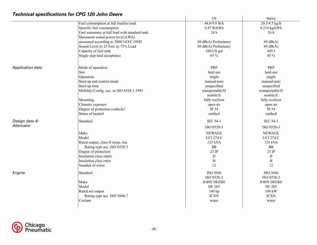
S Metric9 lb/h 20.3/4.5 kg/h/kWh 0.214 kg/kWh h 24 h
reliminary 69 dB(A)reliminary 69 dB(A)S gal 605 l% 85 %
P PRP use land usele single
l/auto manual/autoified unspecified
table/D transportable/Dle/E mobile/Esilient fully resilient air open air54 IP 54ed earthed
4-1 IEC 34-128-3 ISO 8528-3
AGE NEWAGE74 C UCI 274 CVA 125 kVA
BRIP 23 IP
HH12
046 ISO 304628-2 ISO 8528-2EERE JOHN DEERE85 HF 285
hp 104 kWN ICXN
ter water
- 38 -
UFuel consumption at full load/no load 44.6/9.Specific fuel consumption 0.47 lbFuel autonomy at full load with standard tank 24Maximum sound power level (LWA)measured according to 2000/14/EC OND 69 dB(A) PSound Level @ 23 Feet @ 75% Load 69 dB(A) PCapacity of fuel tank 160 USingle step load acceptance 85
Application data Mode of operation PRSite landOperation singStart-up and control mode manuaStart-up time unspecMobility/Config. acc. to ISO 8528-1:1993 transpor
mobiMounting fully reClimatic exposure openDegree of protection (cubicle) IP Status of neutral earth
Design data 4)Alternator
Standard IEC 3ISO 85
Make NEWModel UCI 2Rated output, class H temp. rise 125 k
Rating type acc. ISO 8528-3 BRDegree of protection 23 Insulation class stator HInsulation class rotor HNumber of wires 12
Engine Standard ISO 3ISO 85
Make JOHN DModel HF 2Rated net output 140
Rating type acc. ISO 3046-7 ICXCoolant wa
Technical specifications for CPG 120 John Deere

US Metric
injection direct injectionrbo turbo4 4
US gal 4.5 ltronic electronic
US gal 8.5 lUS gal 16 l Vdc 12 Vdc
3 350A 150 A5xIn 3.5xIn
3 333 A 333 A5xIn 3.5xIn
uplex (2x) GFCI duplex (2x) + E 2p + E 125 V 20 A 125 V
ower (2x) Temp power (2x) N + E 2p + N + E25/250 V 50 A 125/250 V
- 39 -
Combustion system directAspiration tuNumber of cylinders
Swept volume 1.19Speed governing elecCapacity of oil sump 2.2 Capacity of cooling system 4.2 Electrical system 12
Power circuit Circuit-breaker, 3 phaseNumber of poles Thermal release It 1Magnetic release Im 3.
Circuit-breaker, 3 phase, lower voltage (208 V)Number of polesThermal release It 3Magnetic release Im 3.
Outlet sockets GFCI d2p
20 A
Temp p2p +
50 A 1
Technical specifications for CPG 120 John Deere

in the event of a utility power failure (for up to 500 hours is peak continuous rated (as defined in ISO 8528-3) at
mber of hours per year, between stated maintenance inter-wer output during a 24h period shall not exceed the stated
- 40 -
Notes
1) Reference conditions for engine performance to ISO 3046-1.2) See derating diagram or consult the factory for other conditions.3) At reference conditions unless otherwise stated.4) Rating definition (ISO 8528-1):
LTP: Limited Time Power is the maximum electrical power which a generating set is capable of delivering (at variable load), per year of which a maximum of 300 hours is continuous running). No overload is permitted on these ratings. The alternator 25°C.
PRP: Prime Power is the maximum power available during a variable power sequence, which may be run for an unlimited nuvals and under the stated ambient conditions. A 10% overload is permitted for 1 hour in 12 hours. The permissible average poload factor of 70%.
5) Specific mass fuel used: 0.86 kg/l.(a) optional equipment(b) thermal release is higher at 25°C

- 41 -
Generating set
Nominal power output (kVA) at 40°C, 1000m: 33.0kVA
When nominal power is lower then 33kVA => 30kVA, the derating factor is different!
For use of generator outside theseconditions, please contact Atlas Copco.
derating factor %0 5 10 15 20 25 30 35 40 45 50 55
0 100 100 100 100 100 100 100 100 100 97 94 91500 100 100 100 100 100 100 100 100 100 97 94 911000 100 100 100 100 100 100 100 100 100 97 94 911500 97 97 97 97 97 97 97 97 97 94 91 882000 94 94 94 94 94 94 94 94 94 91 88 862500 88 88 88 88 88 88 88 88 88 85 83 803000 88 88 88 88 88 88 88 88 88 85 83 803500 82 82 82 82 82 82 82 82 82 80 77 754000 82 82 82 82 82 82 82 82 82 80 77 75
temperature (°C)
heig
ht (m
)derating factor %
0 5 10 15 20 25 30 35 40 45 50 550 100 100 100 100 100 100 100 100 100 97 94 91
500 100 100 100 100 100 100 100 100 100 97 94 911000 100 100 100 100 100 100 100 100 100 97 94 911500 97 97 97 97 97 97 97 97 97 94 91 882000 94 94 94 94 94 94 94 94 94 91 88 862500 88 88 88 88 88 88 88 88 88 85 83 803000 88 88 88 88 88 88 88 88 88 85 83 803500 82 82 82 82 82 82 82 82 82 80 77 754000 82 82 82 82 82 82 82 82 82 80 77 75
heig
ht (m
)temperature (°C)

- 42 -
Conversion list of SI units into British
units
A temperature difference of 1°C = a temperaturedifference of 1.8°F.
Dataplate
1 bar = 14.504 psi1 g = 0.035 oz1 kg = 2.205 lb1 km/h = 0.621 mile/h1 kW = 1.341 hp (UK and US)1 l = 0.264 US gal1 l = 0.220 lmp gal (UK)1 l = 0.035 cu.ft1 m = 3.281 ft1 mm = 0.039 in1 m³/min = 35.315 cfm1 mbar = 0.401 in wc1 N = 0.225 lbf1 Nm = 0.738 lbf.ftt°F = 32 + (1.8 x t°C)t°C = (t°F - 32)/1.8

- 43 -
Circuit diagrams

Optional equipment
- 44 -
1310 3200 01/00
Applicable for CPG 70 - 90 -120 John Deere - Power circuit
(O)
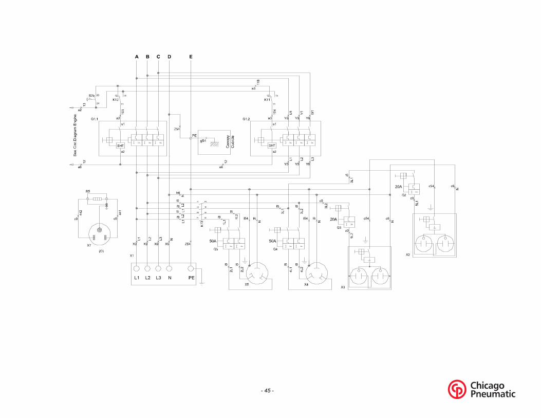
- 45 -

- 46 -
Mark
F1,,5G3K11K12K13N12OQ1,1Q1,2Q2Q3Q4Q5R5R12S2bS10T1,3X1X2X3X4X5X7X9X10X25SxKx
Name
Fuse 4AAlternatorAux, relay (lower volt,)Aux, relay (higher volt,)ContactorAutomatic Voltage RegulatorOptional EquipmentCircuit breaker 3poleCircuit breaker 3poleCircuit breaker 1poleCircuit breaker 1poleCircuit breaker 2poleCircuit breaker 2poleCoolant HeaterVoltage Adjustnent PotmeterEmergency stop (S2a see Engine Circ.)Supply voltage switchCurrent transfornerTerminal boardSocket outletSocket outletSocket outletSocket outletFlanged inletTerminal stripTerminal stripTerminal stripRemote Start/StopContactor Generator Ready(15s. Delayed)

- 47 -
1310 3200 01/00
Applicable for CPG 70 - 90 -120 John Deere - Power circuit
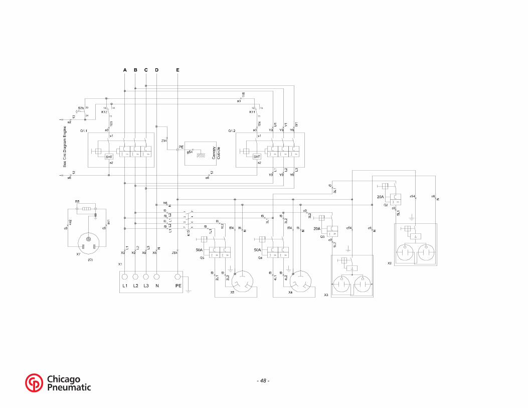
- 48 -

- 49 -
Mark
F1,,5G3K11K12K13N12OQ1,1Q1,2Q2Q3Q4Q5R5R12S2bS10T1,3X1X2X3X4X5X7X9X10X25SxKx
Name
Fuse 4AAlternatorAux, relay (lower volt,)Aux, relay (higher volt,)ContactorAutomatic Voltage RegulatorOptional EquipmentCircuit breaker 3poleCircuit breaker 3poleCircuit breaker 1poleCircuit breaker 1poleCircuit breaker 2poleCircuit breaker 2poleCoolant HeaterVoltage Adjustnent PotmeterEmergency stop (S2a see Engine Circ.)Supply voltage switchCurrent transfornerTerminal boardSocket outletSocket outletSocket outletSocket outletFlanged inletTerminal stripTerminal stripTerminal stripRemote Start/StopContactor Generator Ready(15s. Delayed)


www.cp.com

WalshR
Text Box
AVR - 1089959204 Model - SX 460 Initial set up - Volt pot - next to the 5 wire connections - Turn counterclockwise. Stability pot - At top of AVR to the left of 50 - 60 HZ connection - Set halfway. Potentiometer - Set halfway
walshr
Text Box
1310312470 - 500 Hr 1310312471 - 1000 Hr 1310312472 - 2000 Hr