INSTRUCTION MANUAL - Field Environmental … LMH AND LMH-C FEATURES 1 Battery Compartment Access/...
28
LMH Series Automatic Self-Leveling Rotary Laser with Universal Laser Detector INSTRUCTION MANUAL
Transcript of INSTRUCTION MANUAL - Field Environmental … LMH AND LMH-C FEATURES 1 Battery Compartment Access/...

LMH Series AutomaticSelf-Leveling Rotary Laserwith UniversalLaser Detector
INSTRUCTION MANUAL

Copyright© 2002 CST/Berger. All rights reservedThe information contained herein is propietary information of CST/Berger, and is subject tochange without notice.This document shall not be copied or otherwise reproduced without CST/Berger's written consent.

Thank you for purchasing the LaserMark® LMH Automatic Self-LevelingRotary Laser. Please read this manual thoroughly before operation.
CONTENTS1. LMH Features ................................................................................ 1
2. Laser Safety ................................................................................... 4
3. LMH Operation .............................................................................. 43.1 Leveling ........................................................................................................... 43.2 Re-leveling ....................................................................................................... 53.2.1 Axis Drive Error (Spindle Error) ....................................................................... 53.3 Anti-Drift System (ADS) ................................................................................... 53.4 Grade Mode: Single Axis Grade (LMH-GR and LMH600 Only) .......................... 63.5 Grade Mode: Dual Axis Slope (LMH600 Only) .................................................. 8
4. LMH Applications .......................................................................... 94.1 Procedures for Ceiling Grid Applications ....................................................... 94.2 Procedures for Laydown Applications ......................................................... 104.3 Procedures for General Construction Applications ..................................... 11
5. LMH Battery Replacement ....................................................... 12
6. LMH Calibration .......................................................................... 136.1 Upright Position Peg Test (X axis) ................................................................. 136.1.2 Upright Position Calibration - X axis (LMH, LMH-C, LMH-GR) ....................... 146.1.3 Upright Position Peg Test and Calibration - Y axis (LMH, LMH-C, LMH-GR) . 156.2.1 Upright Position Calibration (LMH600) ......................................................... 166.2.2 Laydown Position Calibration (LMH600) ....................................................... 17
7. Care of LMH Instrument ............................................................ 18
8. LMH Specifications ..................................................................... 18
9. Troubleshooting ......................................................................... 19
10. Warranty ...................................................................................... 20
11. Universal Laser Detector .......................................................... 22

1.1 LMH AND LMH-C FEATURES
1
Battery Compartment Access/5⁄8" x 11 Tripod Mounting Thread
Rotating Laser Head
Anti-DriftSystem OnLED
Power On LED
Built-InHandle
Battery Low LED
Power On/OffButton
Anti-DriftSystemOn/OffButton
SIDE VIEW
LOCATION OFCALIBRATION BUTTONS

2
1.2 LMH-GR FEATURES
POWER
Made in USA
LMH-GR
ANTI-DRIFT SYSTEM
LEVEL ON/OFF
ManualGrade Setting
POWER
Made in USA
LMH-GR
ANTI-DRIFT SYSTEM
LEVEL ON/OFF
ManualGrade Setting
Battery Compartment Access/5⁄8" x 11 Tripod Mounting Thread
Rotating Laser Head
Anti-DriftSystem OnLED
Power On LED
Built-InHandle
Battery Low LED
Power On/OffButton
Manual Grade Button(See LMH600)
Anti-DriftSystemOn/OffButton
Manual GradeAdjustmentButtons
SIDE VIEW
LOCATION OFCALIBRATION BUTTONS

1. LMH600 FEATURES
180º
90º
45º
15º
LM600 Self-Leveling Rotary Laser
Battery Compartment Access/5⁄8" x 11 Tripod Mounting Thread
Self-LevelingRotating Laser Head
Battery Low LEDPower On LED
Variable SpeedRotation Button
Four Speed Selection.Speed Decreases
Each Time Button is Pressed
Power On/OffButton
Out-of-Level Indicator LEDScan Mode ButtonScanning to PresetAngles of 10º, 15º,45º, 90º and 180º to Increase Visibility
Manual Grade ButtonTurns unit to manualmode to allow manual grade setting
Head Positioning Buttonfor Fast and Easy Alignment in Vertical/Horizontal Applications,Clock-Wise and Counter-Clock-Wise Rotation. Pressing and Holding Button Moves theRotating Beam more Quickly
Auto Beam PositioningButton. Positions the
Laser Dot in Plumb Down Position
(Vertical Mode), for Vertical Laydown Set-ups
Manual Grade/SlopeSetting Buttons
180º
90º
45º
15º
LM600 Self-Leveling Rotary Laser
LOCATION OFCALIBRATION BUTTONS
X
Y
3
Power On(if blinking, unit is self-leveling)
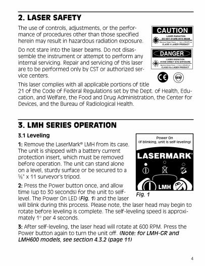
2. LASER SAFETYThe use of controls, adjustments, or the perfor-mance of procedures other than those specifiedherein may result in hazardous radiation exposure.
Do not stare into the laser beams. Do not disas-semble the instrument or attempt to perform anyinternal servicing. Repair and servicing of this laserare to be performed only by CST or authorized ser-vice centers.
This laser complies with all applicable portions of title21 of the Code of Federal Regulations set by the Dept. of Health, Edu-cation, and Welfare, the Food and Drug Administration, the Center forDevices, and the Bureau of Radiological Health.
3. LMH SERIES OPERATION3.1 Leveling
1: Remove the LaserMark® LMH from its case.The unit is shipped with a battery currentprotection insert, which must be removedbefore operation. The unit can stand aloneon a level, sturdy surface or be secured to a5⁄8" x 11 surveyor’s tripod.
2: Press the Power button once, and allowtime (up to 30 seconds) for the unit to self-level. The Power On LED (Fig. 1) and the laserwill blink during this process. Please note, the laser head may begin torotate before leveling is complete. The self-leveling speed is approxi-mately 1° per 4 seconds.
3: After self-leveling, the laser head will rotate at 600 RPM. Press thePower button again to turn the unit off. (Note: for LMH-GR andLMH600 models, see section 4.3.2 (page 11)
Fig. 1
4
3.2 Re-levelingIf the unit is bumped or moved, the unit will automatically attempt tore-level itself. The Power On LED and the laser will blink during thisprocess until the unit is level once again. The laser head will resumerotation at 600 RPM.
Note: For the LMH-GR and LMH600, if the unit is bumped or movedwhile in Manual Grade mode, the unit will not re-level itself.
On the job site, it may be necessary to prevent re-leveling in order toprevent inaccurate measurements by the op-erator. The LMH’s Anti-Drift System (Section3.3) is used for this purpose.
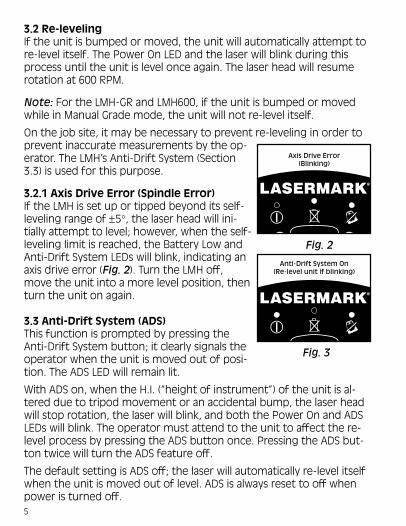
3.2.1 Axis Drive Error (Spindle Error)If the LMH is set up or tipped beyond its self-leveling range of ±5°, the laser head will ini-tially attempt to level; however, when the self-leveling limit is reached, the Battery Low andAnti-Drift System LEDs will blink, indicating anaxis drive error (Fig. 2). Turn the LMH off,move the unit into a more level position, thenturn the unit on again.
3.3 Anti-Drift System (ADS)This function is prompted by pressing theAnti-Drift System button; it clearly signals theoperator when the unit is moved out of posi-tion. The ADS LED will remain lit.
With ADS on, when the H.I. (“height of instrument”) of the unit is al-tered due to tripod movement or an accidental bump, the laser headwill stop rotation, the laser will blink, and both the Power On and ADSLEDs will blink. The operator must attend to the unit to affect the re-level process by pressing the ADS button once. Pressing the ADS but-ton twice will turn the ADS feature off.
The default setting is ADS off; the laser will automatically re-level itselfwhen the unit is moved out of level. ADS is always reset to off whenpower is turned off.
Anti-Drift System On(Re-level unit if blinking)
Axis Drive Error(Blinking)
Fig. 2
5
Fig. 3

Method 2
Method 1
"Y" AxisB
A
Beam fromPivot Point = 2.2"
3.4 Grade Mode: Single Axis Grade (LMH-GR and LMH600 Only)The single grade function is ideal forgeneral site grading, checking excava-tions, landscaping and drainage,and more.Manual grade mode can beactivated by placing the automaticleveling sensor in the OFF position.Pressing the manual grade buttonwill deactivate the sensor.
The selected grade can be as muchas a positive or negative 10%, andset in reference to the Y-axis of theunit.Operator can use one of two methods to generate single-axis grade(Fig. 4). Method 1: Place the unit in the middle of the two points (Aand B) to get a higher distance. Method 2: Place the unit at one point(A) and locate the other point (B).
On the LMH600, you may first press Variable Rotation button and setthe laser to the desired rotation speed. Press the "MANUAL GRADE"button to activate Manual Grade Option. Press the ARROW buttons(Fig. 5B) to adjust to your desired grade.
Y-Axis
Fig. 4
LMH-GR LMH600
NOTE: The total percent grade possible isfrom a perfectly level base position. If theunit is mounted on a tripod head which is notperfectly level, then the grade percentage rangecapable would be reduced by the slope of thebase, as this affects the tilt range of the laserhead. For maximum grade range, ensure a leveltripod head using a spirit level before mountingyour unit.
6
X
“MORE”
“LESS”
Y
“MORE”
“LESS”
LMH-GR and LMH600LMH600 Only
POWER
Made in USA
LMH-GR
ANTI-DRIFT SYSTEM
LEVEL ON/OFF
ManualGrade Setting
180º
90º
45º
15º
LM600 Self-Leveling Rotary Laser
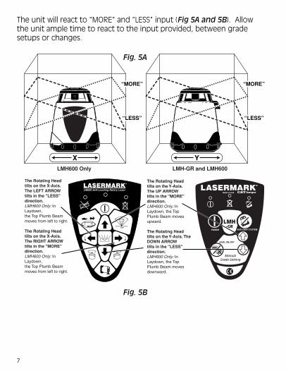
The Rotating Head tilts on the Y-Axis. The UP ARROW tilts in the "MORE" direction.LMH600 Only: In Laydown, the Top Plumb Beam moves upward.
The Rotating Head tilts on the Y-Axis. The DOWN ARROWtilts in the "LESS" direction.LMH600 Only: In Laydown, the Top Plumb Beam moves downward.
The Rotating Head tilts on the X-Axis. The LEFT ARROW tilts in the "LESS" direction.LMH600 Only: In Laydown, the Top Plumb Beam moves from left to right.
The Rotating Head tilts on the X-Axis. The RIGHT ARROW tilts in the "MORE" direction.LMH600 Only: In Laydown, the Top Plumb Beam moves from left to right.
The unit will react to "MORE" and "LESS" input (Fig 5A and 5B). Allowthe unit ample time to react to the input provided, between gradesetups or changes.
Fig. 5A
Fig. 5B
7

3.5 Grade Mode: Dual Axis Slope(LMH600 Only)The dual grade function allows morespecialized site preparations such asroad grading, airport jobs (grading &paving), irrigation, trenching, landfills,slopes and embankments, andpipelaying.
To enter a dual grade setting, press theManual Mode (Grade) button. Then pressthe ARROW buttons to adjust grade (Fig.5B). Allow the unit ample time to react tothe button being pressed. Refer to ex-amples in Fig. 6 to predict your results.
8
Fig. 6
Y
X
Y+
Y-
X+X-
Targ
et
X+Y+
X- Y-
X= –10.00% Y= –10.00%
X+Y+
X- Y-
X= +10.00% Y= +10.00%
X+Y+
X- Y-
X= –10.00% Y= +10.00%
Y +
Y +
X +X -

4. LMH SERIES APPLICATIONSUse your LaserMark® LMH Series Automatic Self-Leveling Laser forthese and many other projects:
Outdoor General Construction Applications & Site Preparation, Grading& Excavating, Batterboards and Foundations, Masonry Work, SettingConcrete Forms, Machinery Installation, Marking Elevation, SepticWork, Paving Roads, Driveways, Checking Depth of Trenches.
4.1 Procedures for Ceiling Grid Applications (LMH600 Only)
1: Attach the LMH Series to the optional wallmount bracket. Be surethe control buttons are facing outward. Tightening the locking screwwill secure the unit to the bracket.
2: After installing the first piece of ceiling trim, attach the wallmountto it. Be sure the wallmount is secure to the trim.
3: Press the Power button. If the out-of-level indicator isblinking, press the manual grade button to put the unitinto automatic mode. Allow the unit to self-level.
4: Adjust the distance of theunit from the grid, typically1.5-inch (38mm) below thegrid. Loosen the adjustment screwand slide the unit up/down on thewall mount. When the desiredheight has been reached, tightenthe adjustment screw to secure
9

10
the unit.
5: Install the ceiling grid. Attach the magnetic laser target to the ceil-ing trim being installed. Adjust the height of the trim until the laserbeam strikes the target.
Note: Placing the unit into Scan Mode will make installation easier andmore effecient.
To place the unit in Scan Mode, press the Scan Mode button until therotating laser head stops. Press and hold either clock-wise or counter-clock-wise Head Positioning button until the laser beam moves to theworking area. Press the Scan Mode button until the rotating beam isscanning the necessary angle.
4.2 Procedures for Laydown Applications (LMH600 Only)
1: Place the unit in the laydown position on a flat, level surface.
2: Press the Power button. If the "Out-of-Level" indicator is blinking,press the Manual Grade button to put the unit in automatic mode.
3: Press the Auto Beam Positioning button; the laser beam will plumbdown over point.
4: Use the left and right Manual Grade buttons for fine adjustment.
LMH600 Shown

4.3 Procedures for General Construction Applications
Note: A level plane of laser light is created by the rotating beam of theLMH Series. The laser light can be used to reference elevations withthe use of a laser detector.
1: Place the unit on a flat, level surface such as a tripod. Setup the unitin an area where it can not be obstructed and it will be set at a conve-nient height.
2: Press the Power button. If the "Out-of-Level" indicator (LMH-GRand LMH600 only) is blinking, press the Manual Grade button to putthe unit in automatic mode.
2a: LMH600 Only – Press the Variable Speed Rotation button to selectthe desire rotation speed of the laser head.
3 : Take elevation readings using the plane of laser light as a reference.
To take readings, attach the laser detector to the grade rod andplace the rod at a point to for an elevation reading. Follow theDetector Operation Procedures in this manual.
11

5. LMH SERIES BATTERY REPLACEMENTYour LaserMark® level will provide approxi-mately 30 hours of intermittent use (variablewith temperature) with four Alkaline “D” cellbatteries. If the Battery Low LED is lit (Fig. 7),or the LMH operates erratically, try replacingthe batteries.
1: Remove the battery tray by unscrewingthe plastic nut around the mounting threadon the bottom of the unit (Fig. 8).
2: Remove the old batteries and replace withfour new “D” cell Alkaline batteries.
3: Replace the battery tray. Make sure the battery contacts betweenthe battery pack and the unit compartment are aligned.
NOTE: Do not mix old and new batteries. Replace all batteries at the same time withnew batteries. Remove batteries before storage of the instrument.
Low Battery
Fig. 7
Rechargeable Battery Packif you are using a rechargeable batterypack (included with Cat. #57-LMHD [120V]or #57-LMHE [230V]), your LMH will pro-vide approximately 14 hours of intermit-tent use with each full charge. The bat-teries will begin to perform optimallyafter five full charges and discharges.
You may charge the battery pack withinthe LMH. Ensure that the power is off,and connect the charging plug to thecharging jack on the bottom of the bat-tery pack. Then plug the charger into theappropriate 120/230V AC outlet. Chargetime is typically around 8 hours. The LMHcan be charged and used at the sametime, but only a minimal charge will beapplied to the battery pack. Fig. 8
12

6. LMH SERIES CALIBRATIONYour LaserMark® level is a sealed unit and iscalibrated to precise accuracies at the factory.However, a calibration check is recommendedbefore the initial use of your laser, and thenperiodically from that point forward. Be sureto allow time (up to 30 seconds) for the unitto completely self-level before each check.
Please note the direction of the X and Y axesfor the unit (Fig. 9). You will need to refer tothis to complete the following steps.
6.1 Upright Position Peg Test (X axis)
1: To test the X axis, mount the LaserMark® on atripod or a level, sturdy surface and placeapproximately 100 feet (30m) away froma wall. Face the right side of the unit(X+ quadrant) to the wall.
2: Press the POWER button andallow the unit to self-level. Usingthe laser detector, locate and markthe position of the laser line on thewall (“A”, Fig. 10).
3: Loosen the LaserMark® from thetripod and rotate the instrument180°. Ensure that the height of thetripod does not change, as this will affect your results. Secure and re-level the unit.
4: Again, locate and mark the position of the laser line on the wall(“B”). No adjustment is necessary if the vertical difference between Aand B is less than 1/8" (3.5mm)
Repeat the above steps to ensure a correct reading. If the distance isgreater than 1/8", you will need to calibrate the X axis (next refer to6.1.2; for LMH600, refer to 6.2.1).
Fig. 9
Y+
Y-
X+X-
100'(30m)
A
B
Fig. 10
13

Calibration ModeX Axis active
6.1.2 Upright Position Calibration - X axis (LMH, LMH-C, LMH-GR)
1: Keep the unit in its current position. PowerOff the unit.
2: Power On the unit while holding the ADSbutton down. You will know if Calibrationmode is activated when the Battery Low andADS LEDs flash alternately. Then, the ADS LEDwill remain lit; this indicates that the unit iscalibrating within the X axis (Fig. 11).
3: Locate the position of the two calibrationbuttons as shown in (Fig. 12), on the LMH-GR the UP and DOWN ARROW buttons change the axis incre-ments. The upper button will produce a positive (+)
4: You must raise or lower the beam to center between points A and Bon the wall (Fig. 13). The unit will react to “+” and “–” input within theX- quadrant, with each single increment moving the beam approxi-mately 1/32" at 100 feet. If B is below A, decrease the increment (-). If Bis above A, increase the increment (+).
5: The adjustments are automatically saved. You must now repeat thepeg test (6.1) to insure you have made the correct calibration. Repeatcalibration if necessary.
Fig. 11
LMH and LMH-C
Fig. 12
Calibrated
A
B
Fig. 13X- facingthe wall
14

6.1.3 Upright Position Peg Test and Calibration - Y axis (LMH,LMH-C, LMH-GR)
If you wish to test the Y axis at the same time as the X axis, simplykeep the unit on from when you tested the X axis and rotate the unit90° so that the front of the unit is facing the wall. Press the ADS but-ton to turn the ADS LED off; you are now calibrating within theY axis (Fig. 14); follow 6.1, steps 2 through 4.
If you are testing the Y axis at a later time than the X axis, mount theLaserMark® on a tripod and place approximately 100 feet (30m) awayfrom a wall, with the front (Y– quadrant) of the unit facing the wall;follow 6.1, steps 2 through 4.
Calibrate as in 6.1.2, adjusting “+” and “–” input as necessary within theY+ quadrant (Fig. 15).
If you are unable to calibrate the unit, or if the difference between points A and B istoo great to calibrate within the range of the unit, please contact CST/Berger or an
authorized service center for assistance.
Calibration ModeY Axis active
Fig. 14
B
A
Calibrated
Fig. 15
Y+ facingthe wall
15
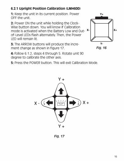
6.2.1 Upright Position Calibration (LMH600)
1: Keep the unit in its current position. PowerOFF the unit.
2: Power ON the unit while holding the Clock-Wise button down. You will know if Calibrationmode is activated when the Battery Low and Out-of-Level LEDs flash alternately. Then, the PowerLED will remain lit.
3: The ARROW buttons will produce the incre-ment change as shown in figure 17.
4: follow 6.1.2, steps 4 through 5. Rotate unit 90degree to calibrate the other axis.
5: Press the POWER button. This will exit Calibration Mode.
Y +
Y +
X +X -
Y+
Y-
X+X-
Fig. 16
Fig. 17
16

6.2.2 Laydown Position Calibration (LMH600)
1: Place the unit in the laydown position on a flat, level surface 100feet (30 meter) from a wall (Fig. 18).
2: Press and hold the Counter-Clockwise Button, and then press thePower Button. Release both button at the same time.
The Out-of-Level LED and Battery Low indicators blink together, Thenthe Power indicator illuminates.
Note: For the most accurate check, allow the unit to operate for atleast 30 seconds before continuing.
3: Place a plumb line at the wall (Fig. 18).
4: Have the rotating beam scan the wall and physically adjust the unitso the beam is in-line with the plumb line.
5: If the beam is not in-line with the plumb line, use the UP ARROWand DOWN ARROW buttons to adjust the beam, until it intersects theplumb line.
6: Press the POWER button. This willexit Calibration Mode.
Plumb Beam
Plu
mb
Lin
e
Rotating Beam (Dashed Line) isshown NOT in-line with plumb line
Fig. 18
17

7. CARE OF LMH INSTRUMENTAlways clean the instrument after use. Use a soft, dry cloth to removeany dirt or moisture from the instrument. Do not use benzene, paintthinner, or other solvents to clean the instrument. Remove batteriesbefore storage of the instrument.
8. LMH SERIES SPECIFICATIONS
noitpircseD HML C-HML RG-HML 006HML
ycaruccAgnileveL'001@"61⁄1±
[email protected]±'001@"23⁄3±)[email protected]±
'001@"61⁄1±)[email protected]±
'001@"61⁄1±)[email protected]±
dednemmoceRegnaRgnikroW
rotcetedresalhtiwretemaid)m016('0002otpU
elbisiVedoiDresaLmaeBdeR
MN056 MN056 MN536 MN536
egnaRgnileveL-fleS º5± º3± º5± º5±
deepSgnileveL-fleS ).xorppa(.ces4repº1
snoisnemiDd"8⁄3-6Xw"4⁄1-6Xh"8
)mm261Xmm951Xmm302(
thgieW seirettabhtiw)gk5.2(.sbl±5.5
rewoP kcapyrettabelbaegrahcerroseirettabenilaklAllecD)4(ruoF
efiLyrettaBseirettabenilaklAhtiwesutnettimretnisruoh±57
;)erutarepmethtiwelbairav(.kcapyrettabdegrahcylluf/wdesusruoh+41
deepSnoitatoR MPR006 MPR006 MPR006elbairaV
006,003,051,0MPR
gnitarepOerutarepmeT
Fº021otFº22)Cº94otCº6-(
18

9. TROUBLESHOOTINGThe following information lists basic tests that can be performed tocheck the LMH in the event of poor performance.
Check Your Batteries: One of the most common causes of perfor-mance failures is due to defective or incorrectly installed batteries.Check to see if any batteries are installed backwards and correct ifnecessary.
• Never selectively replace batteries; always replace all of the batteriesat the same time with new batteries. It is recommended, if possible,that the batteries be checked with a voltmeter or battery tester toconfirm proper voltage.
• Leaky batteries may have damaged the battery contacts in thebattery box.
• Check to see that the battery tray is screwed tightly onto the base ofthe unit. Also, the fit between the battery prongs and the batteriesmay need adjustment, as this fit may vary over different brands ofbattery (especially Energizer™ brand, as they are larger in diameter,preventing a proper connection).
• Alkaline batteries are recommended for the best performance andstorage life. Rechargeable batteries such as Nickel-Cadmium willprovide performance, but are not as desirable due to their lowerterminal voltage. Low cost standard Carbon-Zinc batteries may beused in emergencies, but they should be replaced with alkalinebatteries when available.
Rechargeable Battery Pack: For maximum battery life, the batterypack must contain a full charge. Properly charged, the battery packwill provide approximately 14 hours of service. As in most Ni-Cd bat-tery packs, the closer to a full charge that the pack has, the longer itwill take to attain a full charge. The batteries will begin to perform op-timally after five full charges and discharges.
Unit does not rotate or self-level, or produces Axis Drive Error:Reset the internal processor by turning power off and on again. Youmay also try removing the battery tray for 5 seconds to let the
19

capacitor discharge, then replace the tray and try again.
If the unit rotates but does not self-level, be sure that the Anti-DriftSystem is turned off.
LMH600 Errors:
When an error occurs on theLMH600, turn the unit OFF.Wait 5 seconds, then turnunit ON. If error still occurs,press the Grade Mode button.Use the ARROW buttons torotate the laser head. Thenturn unit OFF and then ONagain. If these procedures donot correct error, contactCST/berger.
X—AXIS ERROR
Y—AXIS ERROR
SPINDLE ERROR
20

10. WARRANTYThis LaserMark® LMH Automatic Self-Leveling Rotary Laser is warrantedto the original purchaser to be free from defects in workmanship andmaterial. CST/Berger will repair or replace any defective part whichmay malfunction under normal and proper use within a period of TWOYEARS from the date of purchase without charge of parts and labor,once delivered and shipped prepaid to CST together with proof ofdate and place of purchase. This warranty is not subject to misuse,abuse, assignment, or transfer. The exclusive remedy under any and allwarrants and guarantees, expressed or implied, is limited to repairand/or replacement as provided herein, and CST shall not be liable fordamages from loss or delay of equipment uses, consequential, or inci-dental damage.
Before returning the unit to CST/Berger, please call (800) 435-1859 for a return authorization number from our Customer Ser-vice Department.
Please fill out and return the attached warranty registrationcard.
21

Universal Laser Detector
1. INTRODUCTIONThe LaserMark® Universal Laser Detector aids in locating and targetinga visible or invisible beam emitted by a rotary laser; perfect for use inoutdoor conditions, where sunlight and distance may make locatingthe beam more difficult.
2. FEATURESLD400 SHOWN
LD400 Includes heavy-duty rod clamp.
3. POWERA 9-volt battery will provide up to 3 months of typical usage. Whenthe unit is turned on and the low battery symbol remains lit, the bat-tery should be replaced.
Beam Capture Window
Power ON/OFF
Beam Resolution
Volume ON/OFF
LCD ReadoutWindow
Speaker LCD ReadoutWindow
Made in USA
Battery Door
50 mm(2.0 in)
22

4. OPERATION1: Mount the unit onto a sighting rod ifyou are using one. Turn on the unit bypressing the ON/OFF pad. The LCD sym-bols will momentarily flash (Fig. 1) andthe “coarse” beam indicator symbol willremain lit and the audio signal will be on.
2: Expose the beam capture window ofthe laser detector towards the directionof the rotating laser.
3: Slowly move the laser detector in anupward and downward direction untilthe LCD beam indicator arrows appearand/or a pulsing audio signal is heard. Use the Beam Resolution fea-ture to choose between the coarse/low setting, used for approximat-ing level or for initial locating of the center level point, the mediumsetting, used for greater accuracy, and the fine/high setting, used forthe most accurate pinpointing of level.
4: Move the detector upward when the low beam indicator light is lit(with volume on, a short pulsing audio tone is heard). Move the detec-tor downward when the high beam indicator arrow is lit (with volumeon, a long pulsing audio tone is heard). When the beam is level, thelevel beam indicator line will be lit and a solid audio tone will be heard.
If the detector is not struck by a laser beam after 5-8 minutes, thedetector will automatically shut itself off to preserve battery life. Turnthe unit back on using the power button.
23
Fig. 1
High Beam
Low Beam
Beam Resolution
Battery Strength
Speaker Volume
LCD Display
Level Beam Indicator

5. SPECIAL FEATURESThis detector has a unique memory feature, which preserves the lastposition of the laser beam if the detector is moved out of the plane oflaser light, as well as built in electronic filtering for bright sunlight andelectromagnetic interference. Three distinct audio tones (high, on-grade, and low) assist targeting from a distance.
Features speaker Off, Loud(105 dBA) and Louder (125+dBA), fine, medium, and coarsebeam resolution settings, andfront and back LCD displays.Seven distinct channels of in-formation (Fig. 2) indicate theposition of the detector in theplane of laser light. As you move the detector closer to the center, thearrows fill in to indicate the laser position.
6. CARE OF YOUR UNIVERSAL LASER DETECTORThis unit is gasket sealed for water and dust protection. Use a soft, drycloth to remove any dirt or moisture from the instrument before stor-age. Do not use benzene, paint thinner, or other solvents to clean theinstrument. Remove battery before long-term storage of the instru-ment.
7. SPECIFICATIONSDimensions: 6.6" h x 3" w x 1" d (169mm x 76mm x 25mm)
Weight: 10 oz. (275g)
Range: up to 2000' (610m)
Beam Detection Sensitivity: Fine, ± .75mm; Medium, ± 1.5mm;Coarse, ± 3mm (sensitivity based on standard conditions with most lasers; may vary
slightly due to make, manufacturer, beam size, or working conditions)
Readout: LCD, LD400-front and rear windows; LD100N-single window
Power: One 9-volt battery; provides 3 months of typical usage
24
Fig. 2

Printed in USA PG 0402 Z93-57-LMHMANUAL