Instruction Manual: ES-665 Series Spring-Loaded … Series Spring-Loaded Thief Hatch! ... The design...
8
ES-665 Series Spring-Loaded Thief Hatch WARNING ! Failure to follow these instructions or to properly install and maintain this equipment could result in an explosion, fire and/or chemical contamination causing property damage and personal injury or death. Enardo spring-loaded hatch must be installed, operated and maintained in accordance with federal, state and local codes, rules and regulations and Emerson Process Management Regulator Technologies Tulsa, LLC instructions. Failure to correct trouble could result in a hazardous condition. Call a qualified service person to service the unit. Installation, operation and maintenance procedures performed by unqualified person may result in improper adjustment and unsafe operation. Either condition may result in equipment damage or personal injury. Only a qualified person shall install or service the spring-loaded hatch. Table of Contents Introduction .................................................................. 1 Specifications .............................................................. 2 Principle of Operation .................................................. 2 Tagging Information......................................................2 Installation ................................................................... 2 Maintenance ................................................................ 4 Parts Ordering ............................................................. 5 Parts List...................................................................... 6 Introduction Scope of the Manual This Instruction Manual provides instructions for installation, startup, maintenance and parts ordering information for the ES-665 Series spring-loaded hatch. Figure 1. ES-665 and ES-665-L Series Spring-loaded Thief Hatch MODEL ES-665 MODEL ES-665-L Instruction Manual D104126X012 December 2017 ES-665 Series North America Only
Transcript of Instruction Manual: ES-665 Series Spring-Loaded … Series Spring-Loaded Thief Hatch! ... The design...

ES-665 Series Spring-Loaded Thief Hatch
Warning!
Failure to follow these instructions or to properly install and maintain this equipment could result in an explosion, fire and/or chemical contamination causing property damage and personal injury or death.Enardo spring-loaded hatch must be installed, operated and maintained in accordance with federal, state and local codes, rules and regulations and Emerson Process Management regulator Technologies Tulsa, LLC instructions. Failure to correct trouble could result in a hazardous condition. Call a qualified service person to service the unit. installation, operation and maintenance procedures performed by unqualified person may result in improper adjustment and unsafe operation. Either condition may result in equipment damage or personal injury. Only a qualified person shall install or service the spring-loaded hatch.
Table of ContentsIntroduction ..................................................................1Specifications ..............................................................2Principle of Operation ..................................................2Tagging Information......................................................2Installation ...................................................................2Maintenance ................................................................4Parts Ordering .............................................................5Parts List......................................................................6
introduction
Scope of the ManualThis Instruction Manual provides instructions for installation, startup, maintenance and parts ordering information for the ES-665 Series spring-loaded hatch.
Figure 1. ES-665 and ES-665-L Series Spring-loaded Thief Hatch
MOdEL ES-665
MOdEL ES-665-L
Instruction ManualD104126X012
December 2017
ES-665 Series
Nor
th A
mer
ica
Onl
y

SpecificationsThe Specifications table lists the specifications for the ES-665 Series spring-loaded hatch. Specification is stamped on the nameplate attached to the hatches.
Principle of OperationEnardo gauge hatches are designed to control evaporation losses and protect tanks against excessive pressure or vacuum. When the storage tank pressure is above the setpoint of the hatch, the center assembly opens to relieve excess pressure. When the overpressure has dissipated, the center assembly reseats onto the base to provide tight seal.
Tagging informationThe ES-665 Series hatch is shipped with a tag already attached to the hatch.For retrofit ES-665 Series center assemblies, the order includes a tag, stainless steel wire and a drive screw. User has the option to attach the tag with wire to the existing hatch lid or to drill a small hole and attach tag with a drive screw on the top of the lid. Examples of tag locations are shown in Figure 2. Location 1 is the hinge pin on the back of the hatch and location 2 is the holes in the ears on the front of the hatch.
installationCauTiOn
Ensure the tank is at atmospheric pressure before opening. a pressure build-up inside the tank can cause a
Product descriptionThe ES-665 Series is the next evolution in spring-loaded thief hatch design with precision-manufactured internal components, a base and a cover. It is intended for use in applications where ultra-tight sealing is required such as sour crude/gas or where strict environmental emissions standards are enforced.
ES-665 Series Spring-Loaded Hatch ModelModel ES-665: is a spring-loaded thief hatch designed with a round base and cover. It is intended for use on steel and fiberglass storage tanks which require a tighter seal for reduced vapor loss.Model ES-665-L: is a spring-loaded thief hatch designed with a long basin and cover. The long basin serves as a thief shelf. The design also includes an inclining base to keep the basin level. This is a long configuration.Model ES-665-B: is a spring-loaded thief hatch designed with a round base and cover. This hatch is provided with a bleeder attachment making it possible to relieve tank pressure before opening the hatch. This bleeder prevents a spray from discharging when the hatch cover is raised. This is a bleeder vent configuration.Model ES-665-LB: is a spring-loaded thief hatch designed with a long basin and cover with an inclining base and bleeder attachment. This is a long and bleeder vent configuration.
Viton® is a mark owned by E. I. du Pont de Nemours and Company.
available ConstructionsSee Product Description
PerformanceTight to 0.10 SCFH at 90% of set pressure, at 68°F / 20°C
Bolt Pattern Nominal 8 in. Flange API Round
Pressure Setting range(1)
4, 6, 8, 12, 16, 24 and 32 oz./sq. in.Vacuum Setting range(1)
0.4, 0.9 and 3.5 oz./sq. in.Temperature range
-4 to 140°F / -20 to 60°CNote: Use Fluorosilicone gaskets for lower temperatures to -40°F / -40°C
Construction MaterialCasting: Aluminum (non-sparking)Pressure Gasket: HNBR (standard), Fluorosilicone, Viton® and Ethylene Propylene Diene Monomer (EPDM)Vacuum Gasket: Fluorosilicone (standard), Viton
and EPDM Food GradeOptional Equipment Base Gasket, Bolt Set, Non-Corrosive Coatingapproximate Shipping Weight
Model ES-665: 25 lbs / 11.3 kg
1. The pressure/temperature limits in this Instruction Manual and any applicable standard or code limitation should not be exceeded.
2
ES-665 Series
Nor
th A
mer
ica
Onl
y
spray to be emitted from the hatch if opened under pressure. Springs are energy storage devices and are dangerous if handled improperly. always use appropriate safety equipment including safety glasses or shields anytime you are working with a spring-loaded hatch.
Warning!
Ensure hardware and tools used during installation do not interfere with or exert upward forces on the hatch base.
Complete ES-665 Series HatchWarning!
The ES-665 Series Hatch is not necessarily grounded when installed on fiberglass reinforced plastic tanks unless the base is electrically bonded to the tank.To avoid personal injury or property damage resulting from the effects of a static electricity discharge from hatch components in a hazardous atmosphere or where the process fluid is combustible, electrically bond the base to the tank with grounding strap.
1. Install the spring-loaded thief hatch on a mating API flange bolting circle of 16 bolt holes on a 10 - 3/8 in. circle for a normal 8 in. opening.
2. For installation of the hatch directly to the tank roof, place the base gasket on the bottom of the hatch flange and place on the tank roof with holes lined up. The slope on the roof should not exceed 5 degrees. Insert the 16 bolts from the bottom up by reaching inside the tank, through the hatch and opening in the tank roof. Attach each nut to the bolt from the outside. Tighten all nuts in a circular manner and make sure the hatch is fastened securely. The bolt size is 5/8 in. The minimum starting torque should be 20 ft-lbs and the maximum torque is 45 ft-lbs.
3. For installation of the hatch to a flanged pipe with an 8 in. API flange pattern, simply place the base gasket on the flanged pipe, line up bolt holes and place hatch on top of base gasket. Install nuts and bolts and tighten in a circular manner. Ensure hatch is fastened securely.
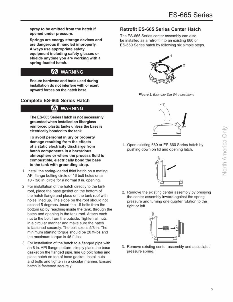
1. Open existing 660 or ES-660 Series hatch by pushing down on lid and opening latch.
2. Remove the existing center assembly by pressing the center assembly inward against the spring pressure and turning one quarter rotation to the right or left.
3. Remove existing center assembly and associated pressure spring.
Retrofit ES-665 Series Center HatchThe ES-665 Series center assembly can also be installed as a retrofit into an existing 660 or ES-660 Series hatch by following six simple steps.
Figure 2. Example Tag Wire Locations
1
2
3
ES-665 Series
Nor
th A
mer
ica
Onl
y

To ensure efficient operation of all hatches, use a clean, nonabrasive, lint-free cloth or paper towel to carefully wipe off the pressure and vacuum seats and gaskets every time the hatch is opened. This prevents accumulation of residue that can deteriorate the performance of the valves.Under average operating conditions, replace the pressure and vacuum gaskets once a year. Replace the base gasket only when a leak is noticed at the bolting area or if the hatch is removed, breaking the seal. If the hatch is continually relieving, the user should be alerted that there is a problem and a close inspection should be made to determine the cause.To easily identify the parts, see Figure 5 for an exploded view of ES-665 Series.
noteFor parts information refer to the catalog data sheet on each model.
gasket and Spring replacement
Vacuum Assembly1. The vacuum gasket is located between the
vacuum pallet and the seal support on the vacuum assembly. The vacuum assembly seals against the underside of the center assembly. To remove the center assembly, depress the center assembly inward and turn one quarter rotation to the right or left (See installation of Retrofit ES-665 Series Center Hatch, step 2). Once the center assembly is removed, remove the cotter pin and the conical shaped vacuum spring from the vacuum stem.
2. Pull the vacuum assembly out from the bottom side of the center assembly. Remove and replace the vacuum gasket (See Table 2 for vacuum gasket options) from between the vacuum pallet and the seal support.
5. Install existing or new pressure spring and ES-665 Series center assembly. Place the pressure spring into the center assembly, then press this combination into the lid. Once the center assembly is pressed fully into lid, turn center assembly one quarter rotation to the right or left, then slowly allow spring to push the center assembly back out until center assembly is secured in the grooves in the lid. If center assembly comes back out fully, follow instructions in this step again until the center assembly is properly secured in the lid.
6. Close the hatch by pressing down on the lid and latching the hatch.
7. Permanently mark through the older model number on the nameplate to ES-665 Series.
MaintenancePerform a scheduled maintenance every three (3)months and more frequently in corrosive or dusty atmospheres. To perform normal maintenance, inspect the pressure gaskets and vacuum gaskets.
4. New ES-665 Series center assembly can be identified by a green anodized vacuum pallet.
Figure 3. ES-665 Series Vacuum Assembly
COunTErSinK SidE uP FOr O-ring
7 1
2
6
3
4
5
4
ES-665 Series
Nor
th A
mer
ica
Onl
y
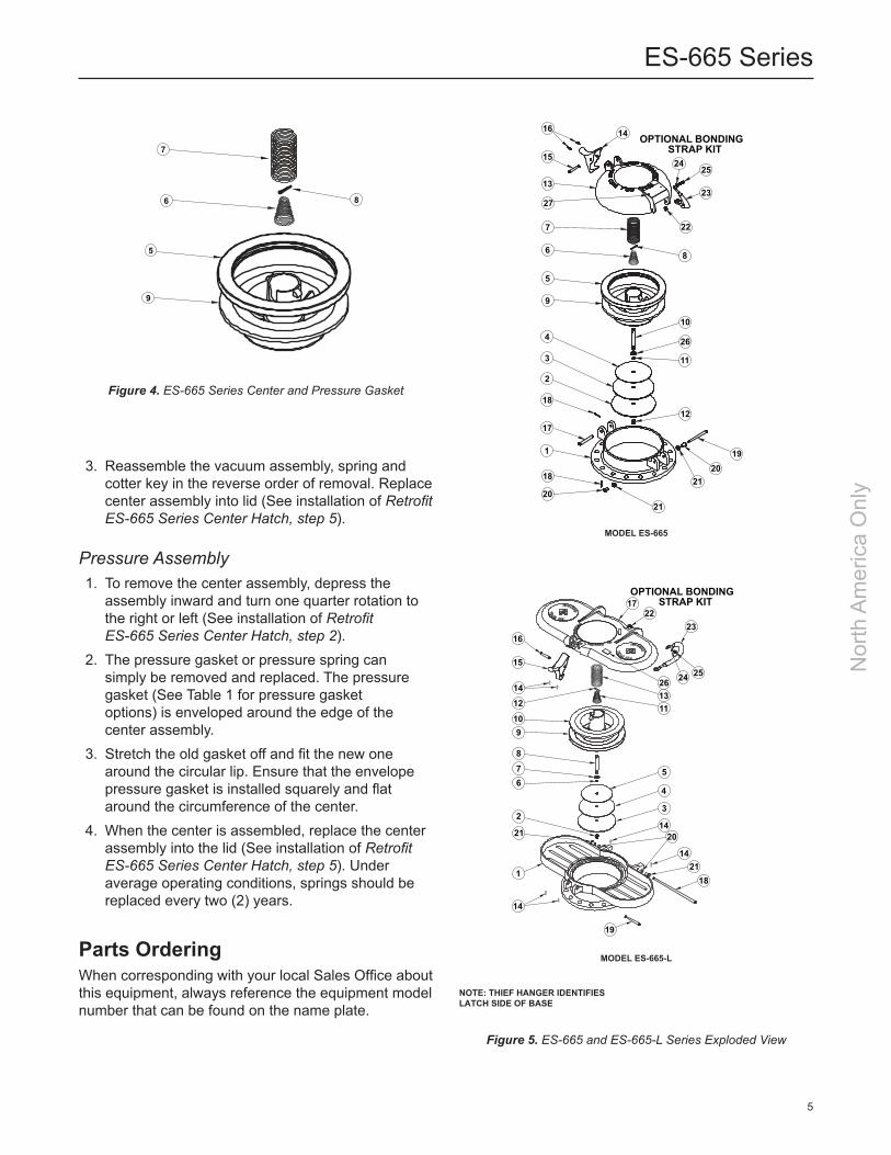
3. Reassemble the vacuum assembly, spring and cotter key in the reverse order of removal. Replace center assembly into lid (See installation of Retrofit ES-665 Series Center Hatch, step 5).
Pressure Assembly1. To remove the center assembly, depress the
assembly inward and turn one quarter rotation to the right or left (See installation of Retrofit ES-665 Series Center Hatch, step 2).
2. The pressure gasket or pressure spring can simply be removed and replaced. The pressure gasket (See Table 1 for pressure gasket options) is enveloped around the edge of the center assembly.
3. Stretch the old gasket off and fit the new one around the circular lip. Ensure that the envelope pressure gasket is installed squarely and flat around the circumference of the center.
4. When the center is assembled, replace the center assembly into the lid (See installation of Retrofit ES-665 Series Center Hatch, step 5). Under average operating conditions, springs should be replaced every two (2) years.
Parts OrderingWhen corresponding with your local Sales Office about this equipment, always reference the equipment model number that can be found on the name plate.
Figure 4. ES-665 Series Center and Pressure Gasket
Figure 5. ES-665 and ES-665-L Series Exploded View
nOTE: THiEF HangEr idEnTiFiES LaTCH SidE OF BaSE
7
6 8
5
9
MOdEL ES-665-L
OPTIONAL BONDING STRAP KIT
21
17
23
2524261311
5
4
3
1420
1421
18
19
14
1
2
67
8
910
1214
15
16
22
MOdEL ES-665
13
27
7
6
5
15
1416
9
4
3
2
1
18
17
18
20
2019
12
11
26
10
8
22
23
2524
21
21
OPTIONAL BONDING STRAP KIT
5
ES-665 Series
Nor
th A
mer
ica
Onl
y

MaTEriaL ParT nuMBEr
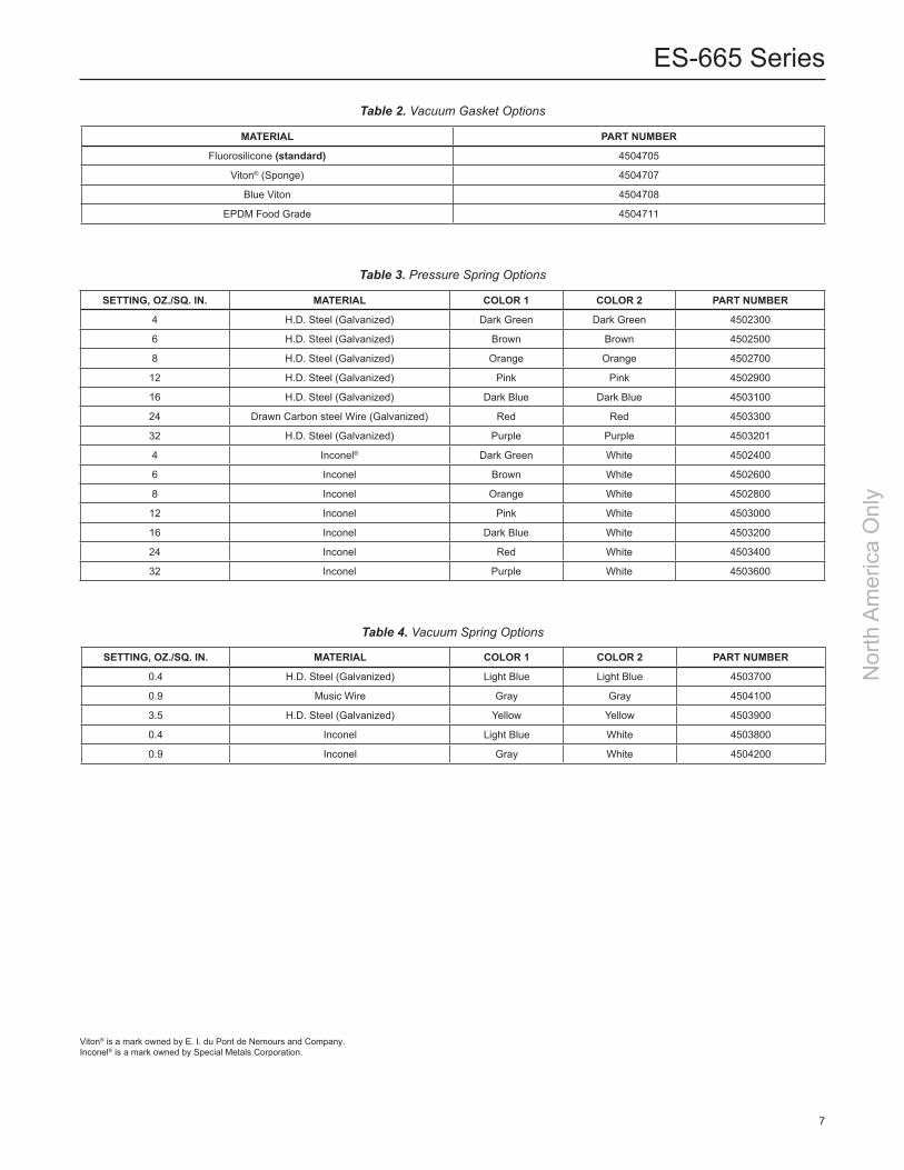
HNBR (standard) 4504601
Blue Viton® 4504603
Fluorosilicone 4504605
EPDM 4504604
Table 1. Pressure (Envelope) Gasket Options
Viton® is a mark owned by E. I. du Pont de Nemours and Company.
Parts List (Figure 5)Type ES-665Key description Part number
1 Base, Hatch 4501102 2 Disk, Pallet 8559029 3 Gasket, Vacuum See Table 3 4 Seal Support 8554636 5 Gasket, Envelope See Table 2 6 Spring, Vacuum See Table 5 7 Spring, Pressure See Table 4 8 Pin, Cotter, 1/8 in. x 1 in. 2022101 9 Center 450105510 Stem 856882411 O-ring, 010 201271012 Nut, 3/8 – 16 in. Hex Nylock 205920113 Lid 452210014 Latch 452420015 Pin, Latch 450510316 Clip, Hinge Pin (2 required) 202710017 Pin, Clevis, 5/16 in. x 2 5/8 in. 450511818 Pin, Cotter, 1/8 in. x 1/2 in. (2 required) 200070319 Pin, Clevis, 5/16 in. x 3 1/2 in. 450511320 Bushing (2 requried) 860040321 Spring, Hinge (2 required) 450400622 Nut, 1/4 – 20 in. (Optional) 201332223 Bonding Strap (Optional) 205000624 Washer, Lock 1/4 in. (Optional) 201256025 Screw, 1/4 in. – 20 x 1 in. (Optional) 202181726 Washer, Flat, 5/16 in. 201258427 Nameplate 4501209
Type ES-665LKey description Part number
1 Base, Hatch 4501801 2 Nut, 3/8 – 16 in. Hex Nylock 2059201 3 Disk, Pallet (Green) 8559029 4 Gasket, Vacuum See Table 3 5 Seal Support 8554636 6 O-ring, 010 2012710 7 Washer, Flat, 5/16 in. 2012584 8 Stem 8568824 9 Gasket, Envelope See Table 210 Center 450105511 Spring, Vacuum See Table 212 Pin, Cotter, 1/8 in. x 1 in. 202210113 Spring, Pressure See Table 414 Clip, Hinge Pin 202710015 Latch, Hatch 452420016 Pin, Latch 450510317 Lid 452280018 Pin, Hatch Hinge 450510119 Pin, Latch 450510720 Spring, Hinge 450400621 Bushing 860040322 Screw, 1/4 in. – 20 x 1 in. (Optional) 202181723 Bonding Strap (Optional) 205000624 Washer, Lock 1/4 in. (Optional) 201256025 Nut, 1/4 – 20 in. (Optional) 201332226 Nameplate 450120927 Washer (Optional) 202060828 Thrust Bearing (Optional) 2020609
6
ES-665 Series
Nor
th A
mer
ica
Onl
y
MaTEriaL ParT nuMBEr
Fluorosilicone (standard) 4504705
Viton® (Sponge) 4504707
Blue Viton 4504708
EPDM Food Grade 4504711
Table 2. Vacuum Gasket Options
SEtting, oz./Sq. in. MaTEriaL COLOr 1 COLOr 2 ParT nuMBEr
4 H.D. Steel (Galvanized) Dark Green Dark Green 4502300
6 H.D. Steel (Galvanized) Brown Brown 4502500
8 H.D. Steel (Galvanized) Orange Orange 4502700
12 H.D. Steel (Galvanized) Pink Pink 4502900
16 H.D. Steel (Galvanized) Dark Blue Dark Blue 4503100
24 Drawn Carbon steel Wire (Galvanized) Red Red 4503300
32 H.D. Steel (Galvanized) Purple Purple 4503201
4 Inconel® Dark Green White 4502400
6 Inconel Brown White 4502600
8 Inconel Orange White 4502800
12 Inconel Pink White 4503000
16 Inconel Dark Blue White 4503200
24 Inconel Red White 4503400
32 Inconel Purple White 4503600
Table 3. Pressure Spring Options
SEtting, oz./Sq. in. MaTEriaL COLOr 1 COLOr 2 ParT nuMBEr
0.4 H.D. Steel (Galvanized) Light Blue Light Blue 4503700
0.9 Music Wire Gray Gray 4504100
3.5 H.D. Steel (Galvanized) Yellow Yellow 4503900
0.4 Inconel Light Blue White 4503800
0.9 Inconel Gray White 4504200
Table 4. Vacuum Spring Options
Viton® is a mark owned by E. I. du Pont de Nemours and Company.Inconel® is a mark owned by Special Metals Corporation.
7
ES-665 Series
Nor
th A
mer
ica
Onl
y

Figure 6. ES-665 Series Spring Identification
PRESSURE SPRINGS
COLOR 1 COLOR 2
VACUUM SPRINGS
COLOR 1 COLOR 2
PRESSURE SPRINGS
COLOR 1 COLOR 2
VACUUM SPRINGS
COLOR 1 COLOR 2
ES-665 Series
Facebook.com/EmersonAutomationSolutions
LinkedIn.com/company/emerson-automation-solutions
Twitter.com/emr_automation
Enardo.com
D104126X012 © 2017 Emerson Process Management Regulator Technologies, Inc. All rights reserved. 12/17. The Emerson logo is a trademark and service mark of Emerson Electric Co. All other marks are the property of their prospective owners. Enardo™ is a mark owned by Regulator Technologies Tulsa, LLC, a business of Emerson Automation Solutions.
The contents of this publication are presented for informational purposes only, and while every effort has been made to ensure their accuracy, they are not to be construed as warranties or guarantees, express or implied, regarding the products or services described herein or their use or applicability. We reserve the right to modify or improve the designs or specifications of such products at any time without notice.
Emerson Process Management Regulator Technologies Tulsa, LLC does not assume responsibility for the selection, use or maintenance of any product. Responsibility for proper selection, use and maintenance of any Emerson Process Management Regulator Technologies Tulsa, LLC product remains solely with the purchaser.
Nor
th A
mer
ica
Onl
y
Emerson Automation Solutions
Americas McKinney, Texas 75070 USA T +1 800 558 5853
+1 972 548 3574Tulsa, OK 74146 USA T +1 918 662 6161
Europe Bologna 40013, Italy T +39 051 419 0611
Asia Pacific Singapore 128461, Singapore T +65 6770 8337
Middle East and Africa Dubai, United Arab Emirates T +971 4 811 8100