
Instruction manual ENESKA 3-2 - joke · Instruction manual ENESKA 3-2 ... Order No. 0 007 525...
18
Instruction manual ENESKA 3-2 Order No. 0 007 500 and 0 007 520
Transcript of Instruction manual ENESKA 3-2 - joke · Instruction manual ENESKA 3-2 ... Order No. 0 007 525...

Instruction manualENESKA 3-2
Order No. 0 007 500 and 0 007 520

Surface TechnologyOberflächentechnik
2
ENESKA 3-2 System overview (Part 1)
Handpiece JBMH 300 NOrder No. 0 009 350
Angle handpiece JKC 345Order No. 0 009 200
Angle handpiece JIC 390Order No. 0 009 250
Handpiece JHG 210Order No. 0 007 650
Handpiece JIG-400Order No. 0 007 530
DIPROFIL® Mini hand-filing machine FMR/N 5 Order No. 0 001 203FMR/N 10 Order No. 0 001 214FMR/N 15 Order No. 0 001 218
DIPROFIL® Transverse handpiece FMV/NOrder No. 0 001 210
Collets CHC
Collets CHG
Collets NKM 6
Collets K-253
Collets K-252
Rapid-chuck handpiece JIR 310 Order No. 0 007 515
DIPROFIL® Hand-filing machine FPT/NROrder No. 0 005 203DIPROFIL® Hand-filing machine FPV/NROrder No. 0 005 205
Mini hand-filing machine JN 38Order No. 0 001 401Hand-filing machine JFMM 3
Order No. 0 005 400
Hand-filing machine FMD/3-2Order No. 0 005 550
Belt grinder JBS 100 • Order No. 0 009 950
Miniature anlge handpiece JMFC 300 SOrder No. 0 009 512
Miniature angle handpiece JMFC 300 MOrder No. 0 009 511
Collets CHH
Collets CHM
Rapid-chuck handpiece JIH 300Order No. 0 009 150

Surface TechnologyOberflächentechnikSurface TechnologyOberflächentechnik
3
ENESKA 3-2 System overview (Part 2)
Control unit NE270 ENESKA 3-2Order No. 0 007 510
Motor cable JENK-410SOrder No. 0 007 506
Micromotor JENK-410SOrder No. 0 007 505
Connection plug and couplingOrder No. 0 007 051 and 0 007 050
Rapid-Change
Foot control FC-64Order No. 0 007 504
Step-down gear RG-01 4:1Order No. 0 009 500
Motor cabel JENK-250TOrder No. 0 007 526
Micromotor JENK-250TOrder No. 0 007 525
Handpiece trayOrder No. 0 007 030
Extension element CN-01 50 mmOrder No. 0 009 505
Surface TechnologyOberflächentechnik
i
!
1
2
4
List of contents
System overview Page 021 List of contents Page 042 Hinweise zur Anleitung Page 043 Safety instructions Page 044 Warranty/Identification Page 055 Device overview Page 066 Technical data Page 077 Operation/Use/ Care Page 088 Troubleshooting Page 149 Telefax form Page 15
Tips on using the manual
Congratulation on the purchase of this device. This manual has been written for the device user to ensure a problem-free operation, care and maintenance.Important instructions and information concerning safety and operational reliability have been highlighted. The symbols used in the manual have the following meanings:
Working and operating processes which must be observed to the letter to exclude any risk to persons.
The illustrations and diagrams are numbered in sequence within each chap¬ter. Some of these illustrations have keys. References to illustrations within the text e. g. (5.1/2) have the following meaning:
5.1 = Figure 5.1 2 = Position 2 in the key to the figure.
Please feel free to call our customer service department at any time should you encoun-ter tech-nical problems which are not dealt with in this manual:
Telephone +49 (0) 22 04 / 8 39 - 0Telefax +49 (0) 22 04 / 8 39 – 60Internet www.joke.de
Working and operating processes which must be observed to the letter to avoid any damage to the device.
Technical information to which the device operator must give special attention.
Surface TechnologyOberflächentechnik
3
5
Safety instructions
Only use the device if in perfect working order and for its intended purpose. You must always pay attention to the instruction manual and safety instructions therein and be aware of the risks! Repair any faults, which could affect the device’s safety immediately by yourself or have these repaired.
1. The unit is designed exclusively for grinding, milling and polishing with the tools listed and approved in the joke catalogue. Any other use will be deemed to be contrary to its intended purpose. The manufacturer cannot be held liable for any resulting damages. The risk is borne solely by the user. Correct use also includes compliance with the inst-ruction manual and an observation of the care and maintenance conditions.
2. Keep the instruction manual handy at the device’s place of use.
3. Pay attention to and observe generally applicable statutory and otherwise binding regu-lations relating to accident prevention and environmental protection in addition to the information provided in the instruction manual!
4. All personnel commissioned to work on or with the device must have read this instruc-tion manual, and particularly the safety instructions chapter, before starting work. This applies especially for personnel who only work with the device occasionally.
5. Stop the device immediately should you notice changes to the device or its operating behaviour that are relevant to its safety. Have these remedied before restarting work.
6. Do not carry out any modifications, additions or conversions to the device! This also applies to the installation and adjustment of safety equipment.
7. Spare parts must meet the technical requirements specified by the manufacturer. This can only be guaranteed with original joke spare parts.
8. Spare parts must meet the technical requirements specified by the manufacturer. This can only be guaranteed with original joke spare parts.
9. Wear safety goggles when working with the handpiece.
10. Personnel undergoing training or in a general apprenticeship should only be allowed to work with the machine under the constant supervision of an experienced operator!
11. Restrain from any type of work that could jeopardise your safety.
12. The device may only be used if all protective and safety equipment is in place and in proper working order.
13. Do not leave the device unattended when switched on!!
14. Stop and secure the device immediately in the event of malfunctions! Faults must reme-died at once.

Surface TechnologyOberflächentechnik
4
6
Warranty
joke warrant the correct manufacture of every joke Technology GmbH product which is delivered in accordance with the terms of contract and delivery.This warranty does not cover damages caused by normal wear and tear, incorrect handling, negligent use, the fitting of non-original spare parts, inadequate care and/or a failure to comply with this technical manual.
The device may only be used by appropriately trained personnel. If it is not, all warranty claims will be forfeited according to the terms of delivery.
The device may only be used by appropriately trained personnel. If it is not, all warranty claims will be forfeited according to the terms of delivery.
Device identification
The manufacturer’s code and type code, CE label and series number can be found on the rear of the control units or in the case of the handpieces on the handle sleeve.
Disposal
This product shall not be treated as household waste. Instead it shall be han-ded over to the applicable collection point for the recycling of electrical and electonic equipment.
Surface TechnologyOberflächentechnik
1
2
4
6
5
3
7
8
i
5
9
7
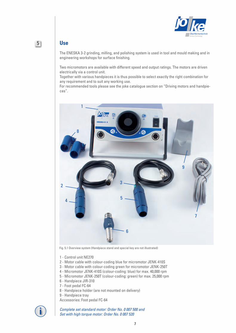
Fig. 5.1 Overview system (Handpiece stand and special key are not illustrated)
Use
The ENESKA 3-2 grinding, milling, and polishing system is used in tool and mould making and in engineering workshops for surface finishing.
Two micromotors are available with different speed and output ratings. The motors are driven electrically via a control unit.Together with various handpieces it is thus possible to select exactly the right combination for any requirement and to suit any working use.For recommended tools please see the joke catalogue section on “Driving motors and handpie-ces”.
1 - Control unit NE2702 - Motor cable with colour-coding blue for micromotor JENK-410S3 - Motor cable with colour-coding green for micromotor JENK-250T4 - Micromotor JENK-410S (colour-coding: blue) for max. 40,000 rpm5 - Micromotor JENK-250T (colour-coding: green) for max. 25,000 rpm6 - Handpiece JIR-3107 - Foot pedal FC-648 - Handpiece holder (are not mounted on delivery)9 - Handpiece trayAccessories: Foot pedal FC-64
Complete set standard motor: Order No. 0 007 500 and Set with high torque motor: Order No. 0 007 520

Surface TechnologyOberflächentechnik
6
8
Technical Data
Control unitSupply voltage 230 V ~ 50 Hz
Fusing 16 A
Dimensions housing with bar (L x B x H) 220 x 254 x 100 mm
Dimensions housing with holder (L x B x H) 220 x 285 x 100 mm
Weight 2.9 kg
Micromotor JENK-410S JENK-210TSpeed 1,000 - 40,000 rpm 1.000 - 25.000 rpm
Output 73 W 76 W
max. Torque 4,3 N/cm2 4,8 N/cm2
Vibration levelless than 2.5 m/s2 when connecting to the micromotor JENK-410S and JIR 310
Noise levelless than 80 dB(A) when connecting to the micromotor JENK-410S and JIR-310
Weight 90 g 147 g
Dimensions (Ø x L) Ø 24.5 x 67.1 mm Ø 29 x 78.5 mm
Degree of protection P 20
Operating time 100 %
Storage case for ENESKA-systems Order No. 0 007 002Dimensions (L x B x H) horizontal 500 x 200 x 400 mm
Dimensions (L x B x H) vertical 500 x 400 x 200 mm
Weight 4.1 kg

Surface TechnologyOberflächentechnik
2
3 6
4 5 7 1
8
910
11
12
13
1415
16 17
1
1819
7
9
Figure 7.1 Control elements (forefront)
Operating elements of the control unit
1 – Handpiece holder 2 – Forward/reverse selector switch 3 – Forward/reverse LED 4 – Speed control knob 5 – Fixpeed switch 6 – Fixpeed LED 7 – Mains switch On/Off 8 – Support (adjust the position by swivelling) 9 – Connection socket B for connection cable10 – Pushbutton connection socket BB11 – Motor B LED12 – Load meter (lead monitor LED)13 – Motor A LED14 – Pushbutton connection socket A15 – Connection socket A for connection cable16 – Handpiece JIR 31017 – Micromotor JENK-250T18 – Smart switch19 – Motor cable

Surface TechnologyOberflächentechnik
i
10
Describing of the operating elements of the control unit
Figure 7.1/1: Handpiece holder takes up the handpieces.
Figure 7.1/2: Forward/reverse selector switch Select the direction of rotation with the forward/reverse selector switch. Each time this switch is pressed, the direction changes. When the FWD./REV. is not lit, it shows right hand rotation (FDW.).
Figure 7.1/4: The rotating regulator allows the rpm of the relevant micromotor to be infinitely varied up to the maximum level 40,000 rpm (is equivalent to 40).
Figure 7.1/5: Memory Speed Function, Fixpeed First with the motor stopped, preset the desired speed on the speed control knob(7.1/4). Next press the fixpeed switch for more than 1 second . A „beep“ sound and the fixpeed LED will light. The motor is now set to run at the fixpeed setting. To change fixpeed memory, repeat the above procedure.
Fixpeed memory cannot be set over 30,000 rpm!
Next press the memory function key for more than 1 second. A signal sounds and the LED display (7.1/6) illuminates. The rpm now remains constant at the saved speed. One speed and one direc-tion of rotation can be saved for each motor output, which is also retained after switching on the control unit again:
• select the appropriate motor (7.1/14 or 7.1/10)• adjust the speed (7.1/4)• observe direction of rotation (7.1/2)• press the memory key for more than 1 second.
The saved speed can be deleted by further pressing the memory key for more than 1 second. A signal sounds. The LED display (7.1/6) is no longer illuminated.
When the ENESKA 3-2 system is shipped from the factory, the fixpeed is preset for bothmotor A and B to 20,000 rpm.
If the foot pedal is used, the speed range can be varied with a saved rpm up to the set speed.
Figure 7.1/7: Mains switch for switching the power supply On/OffFigure 7.1/8: Support
After loosing the hand screws on both sides, the support arm can be pivoted into different resting positions.
Figure 7.1/15 and 7.1/9: Connection sockets A and B for plugging in the connecting cable with corresponding micromotors. The speed set accordingly for the connected micromotor appears on the speed display (7.1/4).
The micromotors connected to both connection sockets A and B cannot be operated simultane-ously.

Surface TechnologyOberflächentechnik
1
2
3
11
Figure 7.2 Control elements (back side)
1 – Connection socket for foot control FC-642 – 230 V mains fuse3 – Connection socket for 230 V mains cable
Figure 7.2/1: As soon as the connection socket for foot control is connected with the unit, the foot control will be active.
Figure 7.2/2: If the unit fails to function after switching on the mains switch, initially check this fuse (see – fuse replacement). The 230 V fine fuse is loca-ted behind the cover.
Figure 7.1/10 and 7.1/14: The connection socket A or B is selected by pressing the pushbuttons for motor B or A.
Figure 7.1/12: Load monitor LED The six LED’s (3 green, 2 orange and 1 red) indicate the load bearing capacity during the working process. Ideally, only the three green LED’s should illuminate during prolonged working processes.
Figure 7.1/11 and 7.1/13: By illuminating, the LED’s next to the pushbuttons show the respective set operating mode.
Figure 7.1/18: On/Off switch The micromotor can be switched on and off on the motor cable (7.1/19).

Surface TechnologyOberflächentechnik
12
Commissioning the control unit and micromotors
1. Place the control unit in a suitable dry place. Usable temperature should be between 0° and +40° C and relative humidity (RH) between 10 and 85 %.
2. Adapt the position, if required by pivoting the support arm (7.1/8).
3. Make sure the speed control knob (7.1/4) is set at the lowest speed position.
4. Connect the mains cable to the control unit and a 230 V socket. Place the unit for quick access of power code (to disconnect in case of emergency).
5. If required, connect the foot switch (7.2/1) to the control unit by means of a cable.
6. Set the mains switch (7.1/7) to the „On“ position; the display of the rpm indicator illuminates.
7. Select the direction with the forward/reverse switch (7.1/2). Each time this switch is pressed, the direction changes. When the FWD/REV LED (7.1/3) is not lit, it shows “right hand rotation”.
8. Connect the handpiece (consider the instruction manual of the handpiece). Insert the motor cord plug into the motor A (7.1/15) or motor B connector (7.1/9) and tighten the motor cord plug nut.
9. Choose between manual -, foot pedal operation or auto speed system to use the micro-motor: Manual operation Set the rotation speed with the speed control knob (7.1/4) and check the speed on the speed display. Select the desired motor by pressing either motor A (7.1/10) or B (7.1/14). After selecting the motor either press the same button one more time, press the smart switch (7.1/18) or the foot pedal again. Foot pedal operation The foot pedal is active in addition to manual mode as soon as it is connected to the control unit. Set the speed and operate the foot switch in order to variably reach the optimum speed. Auto speed system In order to fix the speed, press the foot pedal until the desired speed is reached and subsequently press the pushbutton of the required motor (7.1/14 or 7.1/10). The LED dis-play for the motor illuminates. The speed is maintained even if the foot controller or foot pedal is released. In order to quit the mode, either press once again the pushbutton for motors A or B (7.1/14 or 7.1/10), the button on the handpiece (7.1/18) or the foot pedal.
10. This function is also active when the memory key is used. Plug a second connecting cable with a micromotor into connection socket B if necessary. If you wish to toggle between the micromotors, press the appropriate key (either 7.1/14 or B 7.1/10). The LED display (7.1/13 or 11) indicates which micromotor is operating.

Surface TechnologyOberflächentechnik
13
rotate
Connecting the handpiece to the micromotor
First screw the handpiece onto the micromotor by hand!
If you notice any resistance before the thread is screwed on as far as it ought to go, it means that the drive shaft of the motor and the coupling on the handpiece are not fitting properly one inside the other. In this case turn the shaft of the handpiece until the coupling notches into place. Tighten the handpiece firmly with a hook spanner.
Figure 7.3 Schematic drawing
Do not apply any force! This could cause irreparable damage to the motor bearings.
centre
Do not exceed 13 mm overhang for mounted grindstones. In case of overhang must exceed 13 mm reduce the motor speed in accordance with the following table: Overhang (mm): 20, max. operating speed rpm: N x 0.5Overhang (mm): 25, max. operating speed rpm: N x 0.3Overhang (mm): 50, max. operating speed rpm: N x 0.1

Surface TechnologyOberflächentechnik
14
Unscrewing the handpiece from the micromotor
The handpiece is screwed onto the mircromotor. A hook spanner is used for loosening.
Figure 7.4 Schematic drawing
Quick coupling system joke Rapid-Change for ENESKA 3-2!
• just pull out the old handpiece an push in the new one• modify the motor and handpiece in two steps only:
connector plug und coupling (order no. 0 007 051 and 0 007 050).
Figure 7.5 Rapid-Change
loosen
screw tight
micromotor
handpiece
Fuse replacement Pull out the mains cable (7.2/3) from the socket. The 230 V mains fuse is located behind the cover (7.2/2). Pull out the fuse holder on the rear of the unit.Replace the fuse. The fuse must comply with specification 250 Vac, T1A.
Surface TechnologyOberflächentechnik
15
Additional functions
Tempomat key
An additional speed (less than the preset speed) can be set within the preset speed range using the foot switch:
1. Press the button on the motor cable (7.1/18) for more than one second
2. The speed is saved and can be read on the display (7.1/4).
Memory function key (memory key)
The memory key makes it possible to save a speed and a direction of rotation (clockwise or anticlockwise) for both channels (A or B). Set the desired speed using the rotary knob, in addition to the direction of rotation.
Fixpeed memory cannot be set over 30,000 rpm.
Next press the memory function key for more than 1 second. A signal sounds and the LED display (7.1/6) illuminates. The speed now remains constant however at the saved rpm.
One speed and one direction of rotation can be saved for each motor output, which is also retai-ned after switching on the control unit again: • select the appropriate motor (7.1/14 or 7.1/10) • adjust the speed (7.1/4) • observe direction of rotation (7.1/2) • press the memory key for more than 1 second.
The saved speed can be deleted by further pressing the memory key for more than 1 second. A signal sounds. The LED display (7.1/6) is no longer illuminated.
Maintenance/Care
Control unitThe unit does not require any maintenance. Clean it with a dry, soft cloth.
HandpiecesClean the contact surfaces whenever you change the tool. When you change the handpieces, check that the threads are clean.Ensure absolute cleanliness when changing the collet and only use the spanners provided. Clean up the collet one time/week.
MircromotorsThe brushless motor does not require any maintenance. All ball-bearings are encapsulated and permanently lubricated.
Surface TechnologyOberflächentechnik
- -
8
16
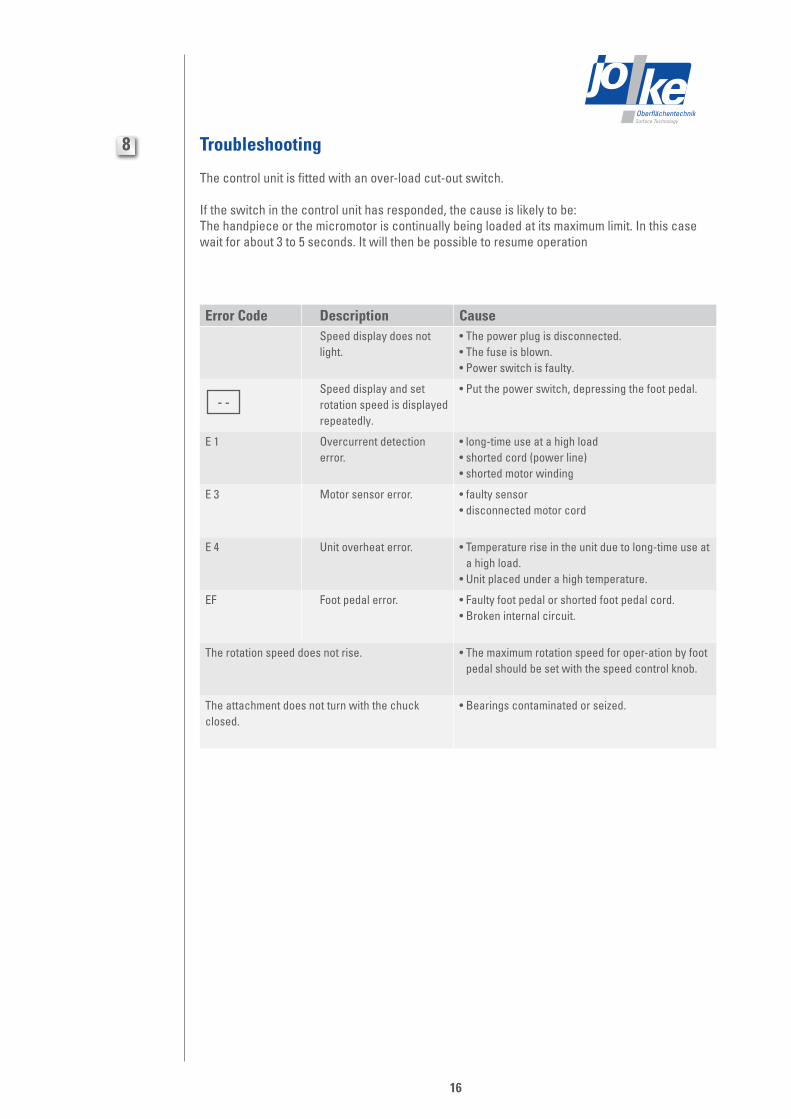
Troubleshooting
The control unit is fitted with an over-load cut-out switch.
If the switch in the control unit has responded, the cause is likely to be:The handpiece or the micromotor is continually being loaded at its maximum limit. In this case wait for about 3 to 5 seconds. It will then be possible to resume operation
Error Code Description CauseSpeed display does not light.
• The power plug is disconnected.• The fuse is blown.• Power switch is faulty.
Speed display and set rotation speed is displayed repeatedly.
• Put the power switch, depressing the foot pedal.
E 1 Overcurrent detection error.
• long-time use at a high load • shorted cord (power line)• shorted motor winding
E 3 Motor sensor error. • faulty sensor• disconnected motor cord
E 4 Unit overheat error. • Temperature rise in the unit due to long-time use at a high load.
• Unit placed under a high temperature.
EF Foot pedal error. • Faulty foot pedal or shorted foot pedal cord.• Broken internal circuit.
The rotation speed does not rise. • The maximum rotation speed for oper-ation by foot pedal should be set with the speed control knob.
The attachment does not turn with the chuck closed.
• Bearings contaminated or seized.

Surface TechnologyOberflächentechnik
9
17
ENESKA 3-2 control unit NE270 Order No. 0 007 510
Rapid-chuck handpiece Type JIR 310 Order No. 0 007 515
Handpiece Type JIH 300 Order No. 0 009 150
Angle handpiece Type JKC 345 Order No. 0 009 200
Angle handpiece Type JIC 390 Order No. 0 009 250
Handpiece Type JBMH 300 N Order No. 0 009 350
Miniature angle handpiece Type JMFC 300 M Order No. 0 009 511
Miniature angle handpiece Type JMFC 300 S Order No. 0 009 512
Handpiece Type JHG 210 Order No. 0 007 650
Handpiece Type JIG 400 Order No. 0 007 530
Hand-filing machine FMD/3-2 Order No. 0 005 550
DIPROFIL® mini hand-filing machine FPT/NR Order No. 0 005 203
Hand-filing machine JFMM 3 Order No. 0 005 400
DIPROFIL® mini hand-filing machine FMR/N 5 Order No. 0 001 203
DIPROFIL® mini hand-filing machine FMR/N 10 Order No. 0 001 214
DIPROFIL® mini hand-filing machine FMR/N 15 Order No. 0 001 218
Mini hand-filing machine JN 38 Order No. 0 001 401
DIPROFIL® transverse handpiece FMV/N Order No. 0 001 210
Date Signature
To
joke Technology GmbHService-DepartementFax: +49 (0) 22 04 / 8 39 - 60
Sender:
Company Name/Departement
Customer No.
Street
Postcode, Town/City Please send us the spare parts drawing and parts list for the following equipment: as a printout (see address overleaf), by Fax, as a pdf file to my e-mail address.

Surface TechnologyOberflächentechnik
joke Technology GmbHAsselborner Weg 14 -16
D-51429 Bergisch GladbachTel. +49 (0) 22 04 / 8 39-0
Fax +49 (0) 22 04 / 8 39-60Mail [email protected] www.joke.de
© Copyright joke Technology GmbH • July 2012 • All rights reserved for technical modifications, inaccuraciesand printing errors. • Reprinting, even in part, only subject to prior written approval.
Brilliant solutions for perfect surfaces


![Dual-Fuel-Driven Bactericidal Micromotor · [21, 22]. Because of the environmentally friendly nature of the magnesium-based micromotor, it has been demon-strated that they have potentials](https://static.fdocuments.us/doc/165x107/5bdb866709d3f2bc1c8c0d17/dual-fuel-driven-bactericidal-micromotor-21-22-because-of-the-environmentally.jpg)


