INSTRUCTION MANUAL - Clay Paky - professional … · 1 INSTRUCTION MANUAL Congratulations on...
20
1 INSTRUCTION MANUAL Congratulations on choosing a Claypaky product! We thank you for your custom. Please note that this product, as all the others in the rich Claypaky range, has been designed and made with total quality to ensure excellent performance and best meet your expectations and requirements. INDEX Page Contents 2 Safety information 3 Unpacking and preparation 4 Installation and start-up 5 Control panel 7 Maintenance 19 Technical information C61515 ENGLISH SCENIUS UNICO
Transcript of INSTRUCTION MANUAL - Clay Paky - professional … · 1 INSTRUCTION MANUAL Congratulations on...

1
INSTRUCTION MANUAL
Congratulations on choosing a Claypaky product!We thank you for your custom.Please note that this product, as all the others in the richClaypaky range, has been designed and made with total qualityto ensure excellent performance and best meet yourexpectations and requirements.
INDEX
Page Contents
2 Safety information
3 Unpacking and preparation
4 Installation and start-up
5 Control panel
7 Maintenance
19 Technical information
C61515
ENGLISH
SCENIUS UNICO

SAFETY INFORMATION
2SCENIUS UNICO
EN
IT
DE
ES
FR
RU
SAFETY INSTRUCTIONSIMPORTANT: Claypaky recommends you carefully read and keep the safety information on this product, alsoavailable in digital format at the following link:http://www.claypaky.it/en Ref: [FIS00L – Safety Information Scenius]
INFORMAZIONI DI SICUREZZAIMPORTANTE: Claypaky raccomanda di leggere accuratamente e conservare le informazioni di sicurezza relativea questo prodotto, sempre reperibili in versione digitale al seguente link:http://www.claypaky.it/en/downloadRif: [FIS00L – Safety Information Scenius]
INFORMATIONEN ZUR SICHERHEITWICHTIG: Claypaky empfiehlt, die Sicherheitsinformationen bezüglich dieses Produkts genau zu lesen undaufzubewahren. Sie sind in Digitalversion immer unter folgendem Link auffindbar:http://www.claypaky.it/en/downloadRef: [FIS00L – Safety Information Scenius]
INFORMACIONES DE SEGURIDADIMPORTANTE: Claypaky recomienda leer detenidamente y conservar la información de seguridad relativa a esteproducto. Además, está disponible una versión digital de la misma en el siguiente enlace:http://www.claypaky.it/en/downloadRef: [FIS00L – Safety Information Scenius]
CONSIGNES DE SÉCURITÉIMPORTANT: Claypaky recommande de lire attentivement et de conserver les informations de sécurité relatives àce produit, disponibles en version digitale au lien suivant:http://www.claypaky.it/en/downloadRéf. : [FIS00L – Safety Information Scenius]
ИНСТРУКЦИЮ ПО ТЕХНИКЕ БЕЗОПАСНОСТИВАЖНО: Claypaky рекомендует внимательно прочитать и сохранить инструкцию по технике безопасностиданного изделия, которая всегда доступна в электронном формате по следующей ссылке:http://www.claypaky.it/en/downloadНаименование: [FIS00L – Safety Information Scenius]

3SCENIUS UNICO
UNPACKING AND PREPARATION
2 x 183102/805
LAM00I(fitted into fixture)
1
90°
90°
90°
90°
LOCKEDUNLOCKED
PAN Mechanism Lock and Release (every 90°) - Fig. 2
TILT Mechanism Lock and Release (every 45°) - Fig. 3
2 3
Packing contents - Fig. 1
45°
45°
45°
45°
45°
UNLOCKED
LOCKED

4SCENIUS UNICO
4
2
1
1
23
5
INSTALLATION AND START-UP
Connecting and disconnecting power cable - Fig. 5
Installing the projector - Fig. 4The projector can be installed on the floor resting on special rubber feet, on a truss or on the ceiling or wall. WARNING:with the exception of when the projector is positioned on the floor, the safety cable must be fitted. (Cod. 105041/001 available on request).This must be securely fixed to the support structure of the projector and then connected to the fixing point at the centre of the base.

5SCENIUS UNICO
Switching on the projector - Fig. 8Press the switch. The projector starts resetting the effects. At the same time, the following information scrolls on the display:
Model Firmware xxx (Fixture ID) System errors SCENIUS Version X.X.X Dmx Address xxx E: ......................... Date - Hour W: .........................
On conclusion of resetting in case of absence of the dmx signal, Pan and Tilt move to the “Home” position (Pan 128 bit - Tilt 128 bit). The controlpanel (Fig. 8) has a display and buttons for the complete programming and management of the projector menu. The display can be in one of twoconditions: rest status and setting status. When it is in the rest status, the display shows the projector’s DMX address and the Fixture ID address(if set). During menu setting status, after a wait time (about 30 seconds) without any key having been pressed, the display automatically returns to rest status.It should be noted than when this condition occurs, any possible value that has been modified but not yet confirmed with theF key will be cancelled.
CONTROL PANEL
12Dmx Address
Warning Message
Fixture ID
7m
8
Connecting to the control signal line (DMX) - Fig. 7Use a cable conforming to specifications EIA RS-485: 2-pole twisted, shielded, 120Ohm characteristic impedance, 22-24 AWG, low capacity. Do not usemicrophone cable or other cable with characteristics differing from those specified. The end connections must be made using XLR type 5-pin male/femaleconnectors. A terminating plug must be inserted into the last projector with a resistance of 120Ohm (minimum 1/4 W) between terminals 2 and 3.IMPORTANT: The wires must not make contact with each other or with the metal casing of the connectors. The casing itself must be connected to theshield braid and to pin 1 of the connectors.
Connecting to the mains supply - Fig. 6
SIGNALSCREEN
DMX 5125 PIN
1234
5
SIGNAL
Mains6
7
Continue ➔

SCENIUS UNICO 6
28
28
Reversal of the display - Fig. 9To activate this function, press UP B and DOWN C keys simultaneously while the display is in the rest mode. This status will be memorised andmaintained even for the next time it will be switched on. To return to the initial state, repeat the operation all over again.Setting the projector starting addressOn each projector, the starting address must be set for the control signal (addresses from 1 to 512). The address can also be set with the projector switched off.Setting the projector Fixture ID On each projector, the Fixture ID address must be set for an easy identification of the fixtures in an installation (ID from 1 to 255).The Fixture ID address can be set with the projector switched off.
9
Functions of the buttons - Using the menu
Setting addresses and options with the projector disconnectedThe projector’s DMX address, as well as other possible operating options, can also be set when the appliance is disconnected from the electricity supply.All that is needed is to pressF to momentarily activate the display and thus access the settings. Once the required operations have been carried out,the display will switch off again after a wait time of 30 seconds.
USING THE MENU:
1) Press F once – “Main Menu” appears on the display.2) Use the UP B and DOWN C keys to select the menu to be used:
• Setup (Setup Menu): To set the setting options.• Option (Option Menu): To set the operating options• Informations (Informations Menu): To read the counters, software version and other information.• Manual Control (Manual control Menu): To trigger the test and manual control functions.• Test (Test Menu): To check the proper functionning of effects• Advanced (Advanced Menu): Access to the "Advanced menu" is recommended for a trained technical personnel.
3) PressF to display the first item in the selected menu.4) Use the UP B and DOWN C keys to select the MENU items.
Confirms the displayed value, or activates the displayed function, or enters the successivemenu.
Decreases the value displayed (with auto-repetitions) or passes to the next item in the menu.
Increases the value displayed (with auto-repetitions) or passes to the previous item in a menu.
Return to the top level
Commute from units, tens, hundreds, in the "Address", "Fixture ID" and "Calibration" menù.
F
CDOWN
BUP
DLEFT
ERIGHT
7SCENIUS UNICO
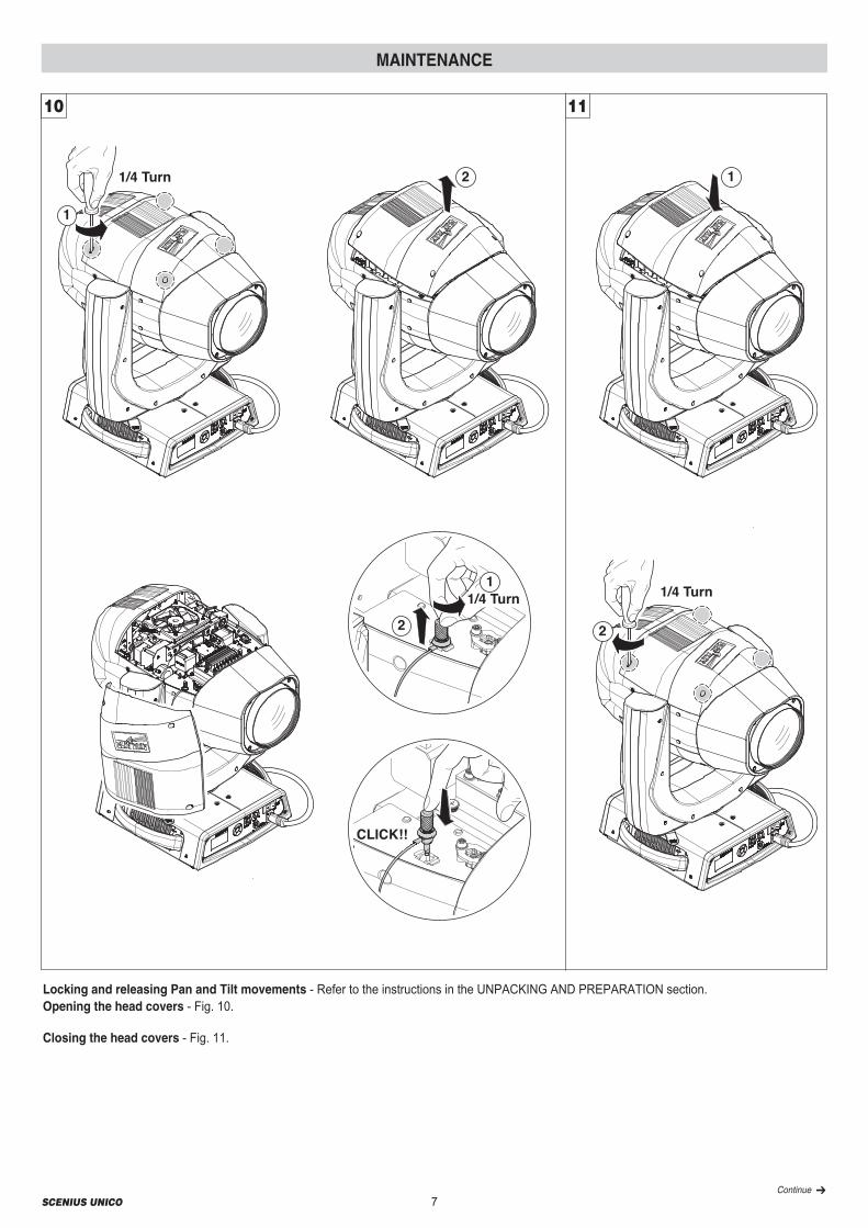
Locking and releasing Pan and Tilt movements - Refer to the instructions in the UNPACKING AND PREPARATION section.Opening the head covers - Fig. 10.
Closing the head covers - Fig. 11.
1/4 Turn
1/4 Turn
1
2 1
2
1/4 Turn2
1
CLICK!!
10 11
MAINTENANCE
Continue ➔

Upper Side
Upper Side
8SCENIUS UNICO
12
Periodical cleaning - Fig. 12To ensure optimal operation and performance for a long time it is essential to periodically clean the parts subject to dust and grease deposits. Thefrequency with which the following operations are to be carried out depends on various factors, such as the amount of the effects and the quality of theworking environment (air humidity, presence of dust, salinity, etc.). Use a soft cloth dampened with any detergent liquid for cleaning glass to remove the dirt from the reflectors, from the lenses and filters. It is recommendedthat the projector undergoes an annual service by a qualified technician for special maintenance involving at least the following operations:• General cleaning of internal parts.• Restoring lubrication of all parts subject to friction, using lubricants specifically supplied by Claypaky.• General visual check of the internal components, cabling, mechanical parts, etc.• Electrical, photometric and functional checks; eventual repairs.NOTE: keep a careful cleaning of the ''CMY/colour filters assembly'' to prevent rapid deterioration.

9SCENIUS UNICO
1
4
3
2
13
Cleaning of the filters - Fig. 13.
Continue ➔

10SCENIUS UNICO
1
2
1
2
1
2
Upper Side
Lower Side
Upper Side
14
Extraction of the effect modules: Preliminary operations - Fig. 14.

11SCENIUS UNICOContinue ➔
1
Lower Side
3
12
Upper Side
15
Extraction of the effect modules: Preliminary operations - Fig. 15.
12SCENIUS UNICO
1
2
Upper Side
16
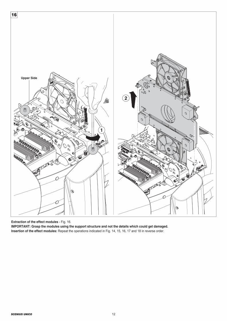
Extraction of the effect modules - Fig. 16.IMPORTANT: Grasp the modules using the support structure and not the details which could get damaged.Insertion of the effect modules: Repeat the operations indicated in Fig. 14, 15, 16, 17 and 18 in reverse order.
13SCENIUS UNICO
1
2
Upper Side17
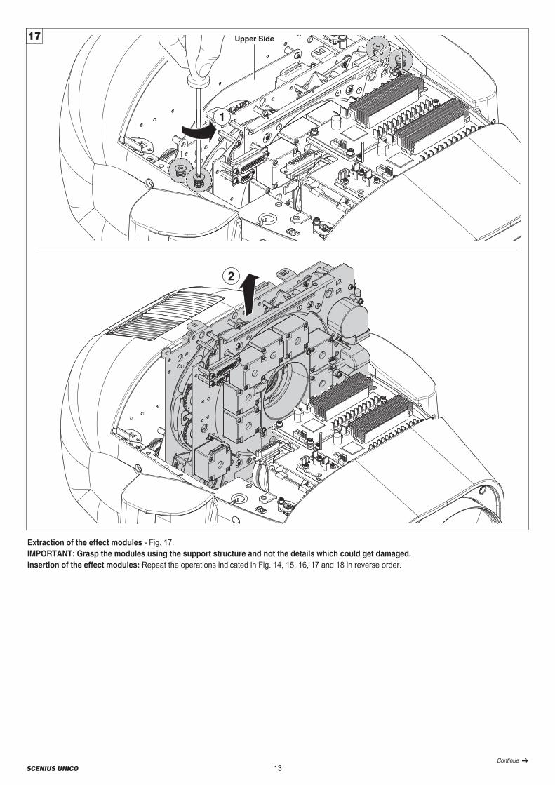
Extraction of the effect modules - Fig. 17.IMPORTANT: Grasp the modules using the support structure and not the details which could get damaged.Insertion of the effect modules: Repeat the operations indicated in Fig. 14, 15, 16, 17 and 18 in reverse order.
Continue ➔

14SCENIUS UNICO
Upper Side
1
Lower Side
Lower Side
3
2
Upper Side
Lower Side
Lower Side18
Extraction of the effect modules - Fig. 18.IMPORTANT: Grasp the modules using the support structure and not the details which could get damaged.Insertion of the effect modules: Repeat the operations indicated in Fig. 14, 15, 16, 17 and 18 in reverse order.

15SCENIUS UNICO
NORMAL
HOT SPOT
1
Upper Side
Lower Side
2
A
1A
3A
Upper Side
Lower Side
20
21
2
1
19
Lamp change - Fig 20Take the new lamp out of its package and insert in the fitting.WARNING: do not touch the lamp’s envelope with bare hands.Should this happen, clean the bulb with a cloth soaked in alcoholand dry it with a clean, dry cloth.CAUTION: Fast lamp ON-OFF cycles (for example 10 minutes ON /10 minutes OFF) will reduce the lamp life.
ATT200/001 is the part number of a CP tool, that could help you to take off the lamp from the fixture.
Lamp regulation - Fig. 21To centre the lamp, turn the three adjusting screws as shown in the figure.
Opening and closing lamp compartment - Fig. 19
Continue ➔

16SCENIUS UNICO
1
2
INDEX
GOD00E/018
GOD00E/005
GOD00E/010GOD00E/017
GOD00E/002
GOD00E/001
23
Replacing rotating gobos (ø 32.8 mm - max 23 mm image – thickness 1.1 mm) - Fig. 23- Before use custom gobos contact Claypaky; - The original gobos have a special coating designed specifically to resist to the high temperatures; - The rotating gobo wheel only use dichroic glass gobos (it is not possible to use metal gobos); - For more information contact Claypaky;
GOBO ROTANTI
Bearing group replacement - Fig. 22
22
Gobo orientation - Fig. 24The pictures shown the correct gobos orientation.
24COATED GLASS GOBOS Grey/Black side away from lamp
Reflective side towards the lamp

17SCENIUS UNICO
Battery removal - Fig. 25This product contains a rechargeable lithium iron tetraphosphate battery. To preserve the environment, please dispose the battery at the endof its life according to the regulation in force.
9
1
2
5
3
4
6
7
8
LiFePO4
25

18SCENIUS UNICO
TECHNICAL INFORMATION
410(16.14")
360(14.17")
486(19.13")
803(31.61")
442(14.50")
627(24.68")
645(25.39")
608(23.93")
POWER SUPPLIES200-240V 50/60 Hz
LAMP SOURCEOSRAM Lok-it! HTI 1400/PS Lamp• Color Temperature: 6.000 K• Life: 750 hrs• Very high CRI• Luminoux flux: 120000 lm• Base PGJ28 Lok-it!• Light can be run at 1400W or 1200W in Energy
Saving mode
OPTICS• 5°-50° Linear Zoom• ø180 mm front lens• Electronic Focusing
COLOR SYSTEM• CMY System• Linear CTO• Color Wheel with 7 color filters
FRAMING SYSTEM• 4 Blades that move separately• Smooth, flexible blade movements at variable
speed• A "total curtain" effect made separately by each
of the 4 blades, in many - shapes and colors• Small and large dynamic profiles• 90° rotation of the entire system, at variable
speed
EFFECTS SECTION• One wheel with 6 rotating gobos• Animation Wheel• Rotating Prism with 4 faces• 16 blades fast Iris• Variable "soft edge" frost• Variable flood frost• Very precise 0-100% dimmer• Fast stop/strobe effect
CONTROL AND PROGRAMMING• 39 or 43 DMX 512 control channels• DMX protocol signal: USITT DMX 512• Art-Net / RDM• Display: LCD 128 x 64 dots, backlit LED, white
on black• Pan and Tilt Resolution: 16 bit• Focus Indexing Resolution: 16 bit• Dimmer Resolution: 16 bit• Rotation gobo Resolution: 16 bit• Movement control: vectorial• DMX signal connection: 5 pole XLR input and
output• Software upload through DMX input / Ethernet
input
BODY• Aluminum and steel structure with plastic covers• Two side handles for transportation• Device locking PAN and TILT mechanisms for
transportation and maintenance
ELECTRONICS• Long life self-charging buffer battery• ON/OFF lamp control from the lighting desk• Function reset from the lighting desk• “AUTOTEST” function from menu ARTNET• Electronic monitoring with status error• Cooling system monitoring• DMX level monitoring on all channels• Internal data transmission diagnostics• Firmware Upgrade with no power• Firmware upload from another fixture
SAFETY DEVICES• Bipolar circuit breaker with thermal protection• Automatic break in power supply in case of
overheating• Forced ventilation with axial fans
WORKING POSITION• Working in any position• Hanging system: with fast-lock omega clamps
(1/4 turn) on the base
WEIGHT45.6 Kg (100.5 lbs)
Giorgio
Casella di testo


CLAYPAKY S.p.A. - Via Pastrengo, 3/b - 24068 Seriate (BG) Italy - Tel. +39-035-654311- Fax +39-035-301876 - www.claypaky.it
IST0
12/0
01 –
EN
- Rev
.0 0
2/20
17