Instruction Manual - American Party Rental · Econo-Floss Instruction Manual Model #3017 Part No....
23
Econo-Floss Instruction Manual Model #3017 Part No. 42131 Revised April 1997 Cincinnati, OH 45241-4807 USA
Transcript of Instruction Manual - American Party Rental · Econo-Floss Instruction Manual Model #3017 Part No....
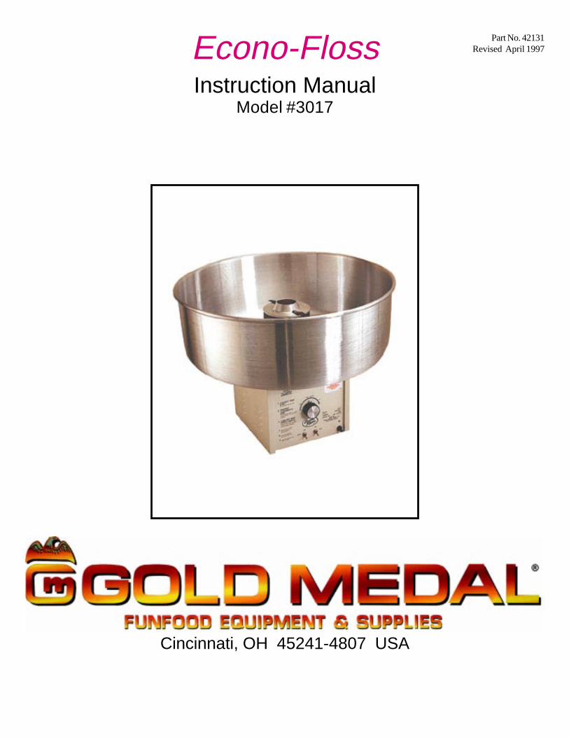
Econo-FlossInstruction Manual
Model #3017
Part No. 42131Revised April 1997
Cincinnati, OH 45241-4807 USA

SAFETY PRECAUTIONS
NOTEThe information, specifications and illustrations contained in this manual representthe latest data available at time of publication. Right is reserved to make changes asrequired at the discretion of Gold Medal Products Company without notice.
Any alterations to this equipment will void the warranty andmay cause a dangerous situation. NEVER make alterationsto the equipment.
Always wear safety glasses when servicing this equipment.
Machine must be properly grounded to prevent electrical shock topersonnel.Do NOT immerse the equipment in water.Always unplug the equipment before cleaning or servicing.
This equipment is designed and sold for commercial use only. Thisequipment is not to be used by the consumer in home use. Do not allowdirect contact of this equipment by the public when used in food servicelocations. Only personnel trained and experienced in the equipmentoperation may operate this equipment.Carefully read all installation instructions before operating the equipment.
Floss head rotates at 3450 RPM. Operator must keep handsand face clear of the floss head and keep spectators at areasonable distance.
Econo-Floss
MODEL #30171
INTRODUCTION
Your ECONO-FLOSS machine has a one year warranty. This does NOT cover the ribbons, bandsor motor bearings since they can be damaged by the operator.
After unpacking, check thoroughly for any damage which may have occurred in transit. Claimsshould be filed immediately with the transportation company. The warranty also does not coverdamage that occurs in transit or damage caused by abuse or consequential damage due to theoperation of this machine, since it is beyond our control.
ELECTRICAL REQUIREMENTS
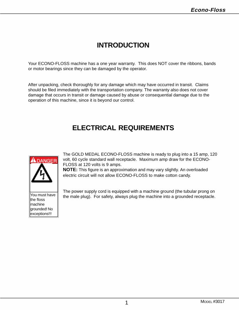
The GOLD MEDAL ECONO-FLOSS machine is ready to plug into a 15 amp, 120volt, 60 cycle standard wall receptacle. Maximum amp draw for the ECONO-FLOSS at 120 volts is 9 amps.NOTE: This figure is an approximation and may vary slightly. An overloadedelectric circuit will not allow ECONO-FLOSS to make cotton candy.
The power supply cord is equipped with a machine ground (the tubular prong onthe male plug). For safety, always plug the machine into a grounded receptacle.You must have
the flossmachinegrounded! Noexceptions!!!
Econo-Floss
MODEL #30172
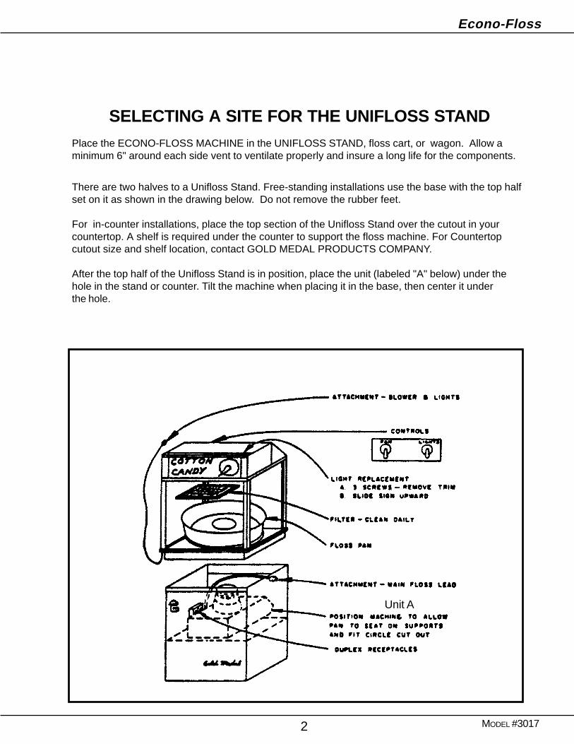
SELECTING A SITE FOR THE UNIFLOSS STANDPlace the ECONO-FLOSS MACHINE in the UNIFLOSS STAND, floss cart, or wagon. Allow aminimum 6" around each side vent to ventilate properly and insure a long life for the components.
There are two halves to a Unifloss Stand. Free-standing installations use the base with the top halfset on it as shown in the drawing below. Do not remove the rubber feet.
For in-counter installations, place the top section of the Unifloss Stand over the cutout in yourcountertop. A shelf is required under the counter to support the floss machine. For Countertopcutout size and shelf location, contact GOLD MEDAL PRODUCTS COMPANY.
After the top half of the Unifloss Stand is in position, place the unit (labeled "A" below) under thehole in the stand or counter. Tilt the machine when placing it in the base, then center it underthe hole.
Unit A

Econo-Floss
MODEL #30173
1 2
3 4
INSTALLATION OF WHIRL GRIP FLOSS STABILIZERThe Whirl Grip Floss Stabilizer works to keep floss from leaving the pan. Install as shown in thediagrams below.
Wash the floss pan thoroughly with soap and water then dry completely. Secure the Floss Stabi-lizer around floss pan. Place the aluminum pan over the floss head of the machine with the flosshead extending up through the center of the pan. Note required air space in diagram 4 below.
Econo-Floss
MODEL #30174
Before Plugging in the Machine
Make sure padding or restraints to prevent shipping damage are removed.
Lower the shipping bracket so the bell housing floats freely on the springs. Turn then push downthe two knobs on each side of the cabinet top to lower the bracket completely.
Make sure the floss ribbon (heating element) located inside the head assembly has not shaken outof the band during transportation. If the ribbon is out of the band, push it back into place manually.
Plugging in the Machine
Plug in the attachment cord from the lights and blower. Plug in the attachment cord from the flossmachine to the duplex plug in the base. Connect the lead-in cord from the base of the UniflossStand to an outlet capable of carrying the amperage described on page 1 of the manual.
After connecting to the power supply, you are ready to make cotton candy.
Controls and Functions
MAIN SWITCH - Turns motor "on" or "off" and supplies current to the heat switch.
HEAT SWITCH - Turns current to the ribbon "on" or "off."
HEAT CONTROL - Increases or decreases voltage to ribbon wire heating element using a gradu-ated dial. The ECONO-FLOSS only has the normal position. All dial settings are at line voltage orbelow.
Econo-Floss
MODEL #30175
OPERATING INSTRUCTIONS
The easiest way to make sure you have the right sugar and proper flavor and colors is to useGOLD MEDAL FLOSSUGAR. FLOSSUGAR gives good, rich colors and flavors, and does notexceed the color limitations imposed by the Food and Drug Administration. FLOSSUGARcomes in sealed, plastic-coated cartons with handy pouring spouts for filling. If you do not usePRE-MIXED products, we suggest you mix your own using our FLOSSINE and your sugar.Follow the directions on the can and mix well. Dampening the sugar at a rate of about onetablespoon of water to five pounds of sugar will bring out bright colors. DO NOT use excesscolor. Using more color than recommended will not deepen the color of the floss; there is a limitto how dark the floss will be since it is 98% air. If you use your own flavors in cotton candy,make sure they are not gum or starch based; these items burn on the ribbons.
Heat Control Setting Test
1. Follow steps on page 4 to supply power.
2. With main switch still OFF, fill floss head. Always fill it 90% full with sugar. This 90% level isnecessary to obtain a balanced condition in the floss head. DO NOT OVERFILL! Excessivevibration will occur if overfilled. Before turning the power on, manually spin the head to balanceout the sugar. This will eliminate excessive vibration of the head.Important: NEVER add sugar when motor is running.
3. Turn MAIN SWITCH and HEAT SWITCH "ON."
4. Turn heat control knob clockwise to maximum setting to intiate the fastest possible warm up.
5. The machine should start making floss in a few seconds. When the unit reaches proper heat, itmay start to smoke. Turn the heat control knob counter clockwise to eliminate smoking.
6. Once you find the ideal setting for the HEAT CONTROL, operate the setting near this positioneach time.
CAUTIONNever operate equipment for a prolonged period of time with the HEATCONTROL in a position that causes the sugar to smoke.This will resultin excessive carbonization of the ribbon (heat element). If you smellburning sugar or see smoke, reduce the heat.
Keep foreign objects out of the head.Floss head rotates at 3450 RPM. Operator must keep hands andface clear of floss head and keep spectators at a reasonabledistance. For safety, always use a floss bubble.
Econo-Floss
MODEL #30176
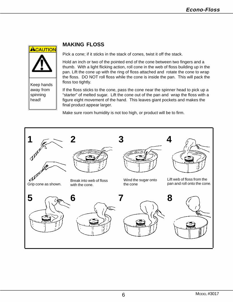
MAKING FLOSS
Pick a cone; if it sticks in the stack of cones, twist it off the stack.
Hold an inch or two of the pointed end of the cone between two fingers and athumb. With a light flicking action, roll cone in the web of floss building up in thepan. Lift the cone up with the ring of floss attached and rotate the cone to wrapthe floss. DO NOT roll floss while the cone is inside the pan. This will pack thefloss too tightly.
If the floss sticks to the cone, pass the cone near the spinner head to pick up a“starter” of melted sugar. Lift the cone out of the pan and wrap the floss with afigure eight movement of the hand. This leaves giant pockets and makes thefinal product appear larger.
Make sure room humidity is not too high, or product will be to firm.
Grip cone as shown.Wind the sugar ontothe cone
Break into web of flosswith the cone.
Lift web of floss from thepan and roll onto the cone.
1 2 3 4
5 6 7 8
Keep handsaway fromspinninghead!
Econo-Floss
MODEL #30177
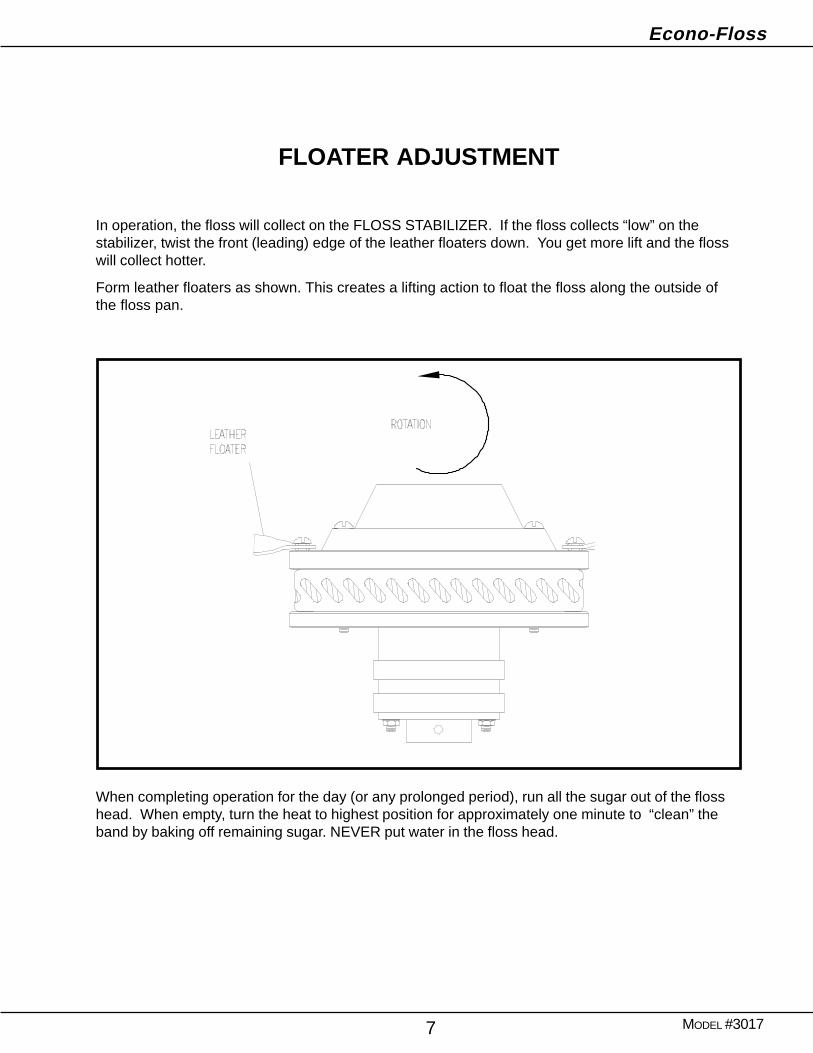
FLOATER ADJUSTMENT
In operation, the floss will collect on the FLOSS STABILIZER. If the floss collects “low” on thestabilizer, twist the front (leading) edge of the leather floaters down. You get more lift and the flosswill collect hotter.
Form leather floaters as shown. This creates a lifting action to float the floss along the outside ofthe floss pan.
SHUT DOWN PROCEDURE
When completing operation for the day (or any prolonged period), run all the sugar out of the flosshead. When empty, turn the heat to highest position for approximately one minute to “clean” theband by baking off remaining sugar. NEVER put water in the floss head.
Econo-Floss
MODEL #30178
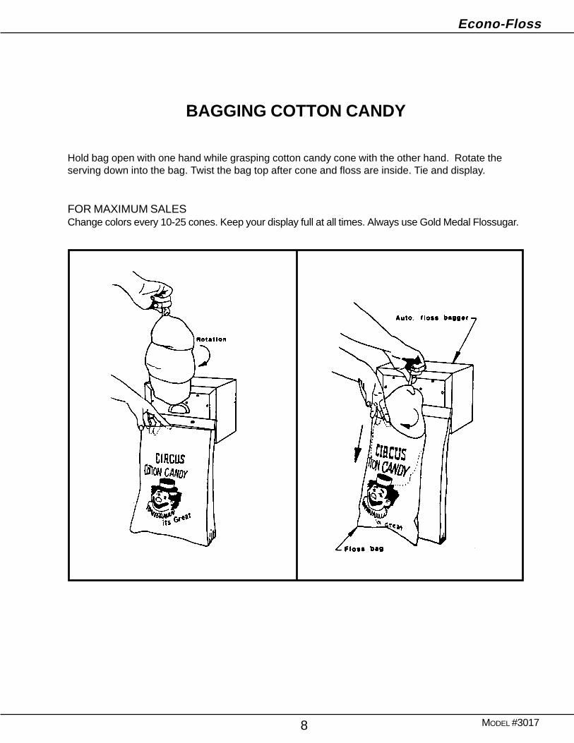
BAGGING COTTON CANDY
Hold bag open with one hand while grasping cotton candy cone with the other hand. Rotate theserving down into the bag. Twist the bag top after cone and floss are inside. Tie and display.
FOR MAXIMUM SALESChange colors every 10-25 cones. Keep your display full at all times. Always use Gold Medal Flossugar.
Econo-Floss
MODEL #30179
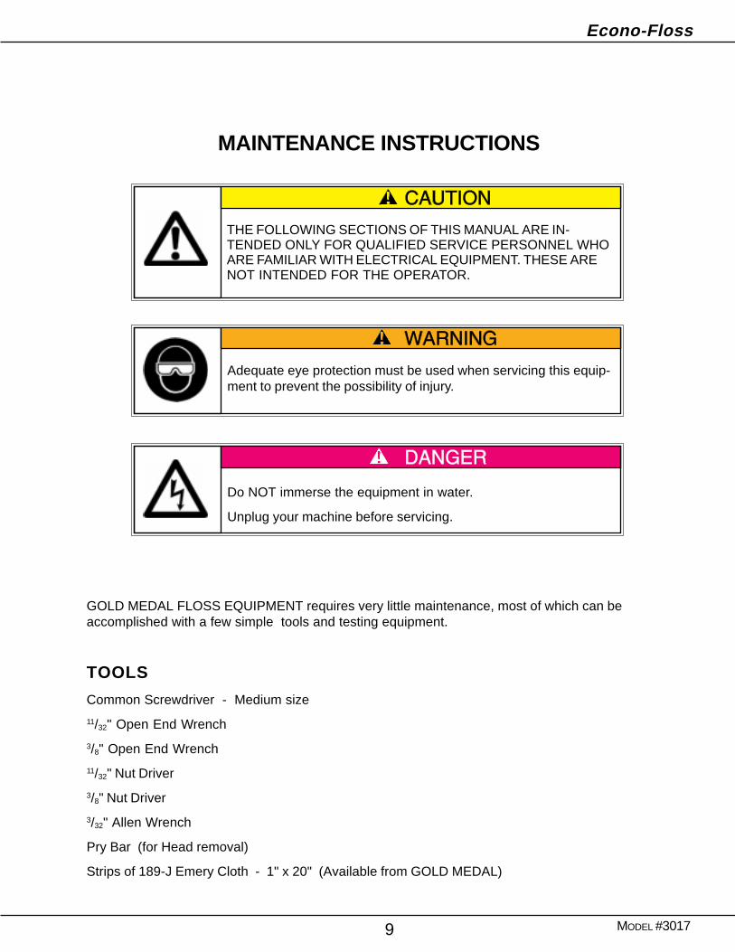
MAINTENANCE INSTRUCTIONS
THE FOLLOWING SECTIONS OF THIS MANUAL ARE IN-TENDED ONLY FOR QUALIFIED SERVICE PERSONNEL WHOARE FAMILIAR WITH ELECTRICAL EQUIPMENT. THESE ARENOT INTENDED FOR THE OPERATOR.
Adequate eye protection must be used when servicing this equip-ment to prevent the possibility of injury.
Do NOT immerse the equipment in water.
Unplug your machine before servicing.
GOLD MEDAL FLOSS EQUIPMENT requires very little maintenance, most of which can beaccomplished with a few simple tools and testing equipment.
TOOLS
Common Screwdriver - Medium size
11/32" Open End Wrench
3/8" Open End Wrench
11/32" Nut Driver
3/8" Nut Driver
3/32" Allen Wrench
Pry Bar (for Head removal)
Strips of 189-J Emery Cloth - 1" x 20" (Available from GOLD MEDAL)
Econo-Floss
MODEL #301710
FLOSS BANDS AND RIBBONS
The GOLD MEDAL ECONO-FLOSS machine is equipped with a patent pending FLOSS BANDdesigned to give long life, trouble-free service with little care. DO NOT scratch the band. To clean,unplug the machine and wipe with a damp cloth.
GOLD MEDAL Floss Ribbons (heat elements) are made of nickel wire with ceramic insulation atthe terminal point and on the lead wires. They are designed to be as reliable as the GOLD MEDALFloss Bands: however, the ribbons must be handled carefully. DO NOT stretch the ribbon or it willnot fit inside the band properly. Also, the ceramic insulator on the lead wires will break if the wiresare bent sharply. Bend gradually when installing ribbons.
Head gaskets are made of quality gasket material and offered at a low cost to allow owners toreplace them when removing and replacing the band. Never use a gasket which is fractured;centrifugal force can throw it off the equipment with considerable force.
Disassembly and Removal
1 Remove all sugar from the head of the machine before disassembling. If the unit isinoperative, turn the machine on its side and shake the sugar out.
2 Remove the four spinner cap retainer screws and spinner cap. In some cases, the sugar hascaused the cap and band to stick together. Applying gentle pressure with the heel of the handshould free the parts for removal.
3 Remove the element lead wire retaining nuts with a 3/8" nut driver and remove the element leadwires from the studs in the floss head. This will allow the band and ribbons to be removed.
4 Remove the band and ribbons. Run hot water over them to remove the carbonized sugar. Ifthere is excessive sugar build-up, soak the band and ribbons in hot water until the sugardissolves. When the sugar has been removed, tap the band in the palm of your hand to loosenthe ribbons for removal.
5 Inspect, then clean or replace band and ribbons. The primary reason for ribbon replacement isa broken or shorted ribbon. If the ribbon is being cleaned only, an additional hot water soakshould remove carbon build-up.
Econo-Floss
MODEL #301711
If carbon remains after soaking, burn it off by inducing electric current through the ribbon. Turn theribbon inside out so the lead wires are pointed outward. Hook up a test cord (an extension cord withclips that can be connected to the ribbon lead wires) and place the ribbon on a nonconductor suchas a brick or china plate. Plug the test cord in and let the ribbon flow a cherry red. Leave the cordplugged in no longer than one minute. Unplug and let it cool for a couple minutes. While it is stillunplugged, shake it a couple of times so pieces of carbon fall away. If necessary, repeat the pro-cess until all of the carbon is removed.
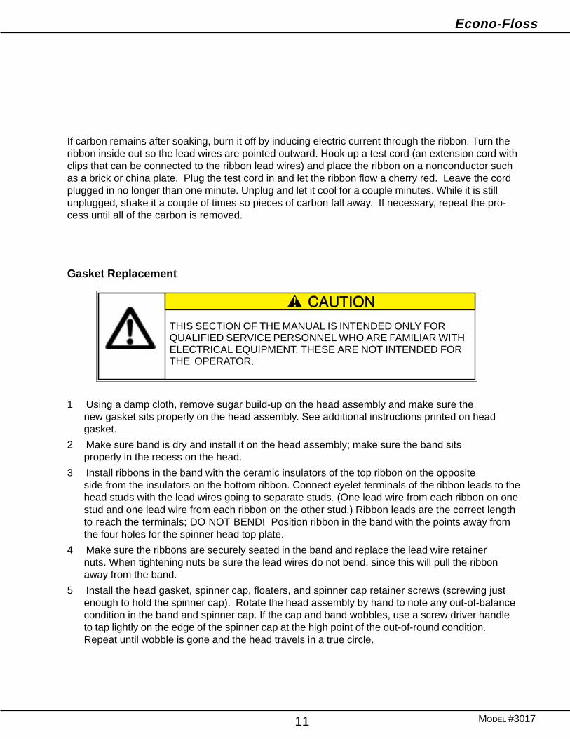
Gasket Replacement
1 Using a damp cloth, remove sugar build-up on the head assembly and make sure thenew gasket sits properly on the head assembly. See additional instructions printed on headgasket.
2 Make sure band is dry and install it on the head assembly; make sure the band sitsproperly in the recess on the head.
3 Install ribbons in the band with the ceramic insulators of the top ribbon on the oppositeside from the insulators on the bottom ribbon. Connect eyelet terminals of the ribbon leads to thehead studs with the lead wires going to separate studs. (One lead wire from each ribbon on onestud and one lead wire from each ribbon on the other stud.) Ribbon leads are the correct lengthto reach the terminals; DO NOT BEND! Position ribbon in the band with the points away fromthe four holes for the spinner head top plate.
4 Make sure the ribbons are securely seated in the band and replace the lead wire retainernuts. When tightening nuts be sure the lead wires do not bend, since this will pull the ribbonaway from the band.
5 Install the head gasket, spinner cap, floaters, and spinner cap retainer screws (screwing justenough to hold the spinner cap). Rotate the head assembly by hand to note any out-of-balancecondition in the band and spinner cap. If the cap and band wobbles, use a screw driver handleto tap lightly on the edge of the spinner cap at the high point of the out-of-round condition.Repeat until wobble is gone and the head travels in a true circle.
THIS SECTION OF THE MANUAL IS INTENDED ONLY FORQUALIFIED SERVICE PERSONNEL WHO ARE FAMILIAR WITHELECTRICAL EQUIPMENT. THESE ARE NOT INTENDED FORTHE OPERATOR.
Econo-Floss
MODEL #301712
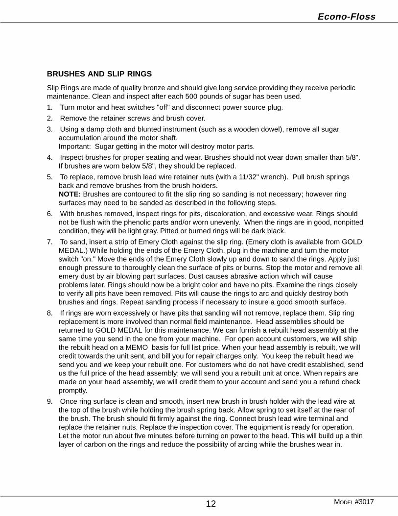
BRUSHES AND SLIP RINGS
Slip Rings are made of quality bronze and should give long service providing they receive periodicmaintenance. Clean and inspect after each 500 pounds of sugar has been used.
1. Turn motor and heat switches "off" and disconnect power source plug.
2. Remove the retainer screws and brush cover.
3. Using a damp cloth and blunted instrument (such as a wooden dowel), remove all sugaraccumulation around the motor shaft.Important: Sugar getting in the motor will destroy motor parts.
4. Inspect brushes for proper seating and wear. Brushes should not wear down smaller than 5/8".If brushes are worn below 5/8", they should be replaced.
5. To replace, remove brush lead wire retainer nuts (with a 11/32" wrench). Pull brush springsback and remove brushes from the brush holders.NOTE: Brushes are contoured to fit the slip ring so sanding is not necessary; however ringsurfaces may need to be sanded as described in the following steps.
6. With brushes removed, inspect rings for pits, discoloration, and excessive wear. Rings shouldnot be flush with the phenolic parts and/or worn unevenly. When the rings are in good, nonpittedcondition, they will be light gray. Pitted or burned rings will be dark black.
7. To sand, insert a strip of Emery Cloth against the slip ring. (Emery cloth is available from GOLDMEDAL.) While holding the ends of the Emery Cloth, plug in the machine and turn the motorswitch "on." Move the ends of the Emery Cloth slowly up and down to sand the rings. Apply justenough pressure to thoroughly clean the surface of pits or burns. Stop the motor and remove allemery dust by air blowing part surfaces. Dust causes abrasive action which will causeproblems later. Rings should now be a bright color and have no pits. Examine the rings closelyto verify all pits have been removed. Pits will cause the rings to arc and quickly destroy bothbrushes and rings. Repeat sanding process if necessary to insure a good smooth surface.
8. If rings are worn excessively or have pits that sanding will not remove, replace them. Slip ringreplacement is more involved than normal field maintenance. Head assemblies should bereturned to GOLD MEDAL for this maintenance. We can furnish a rebuilt head assembly at thesame time you send in the one from your machine. For open account customers, we will shipthe rebuilt head on a MEMO basis for full list price. When your head assembly is rebuilt, we willcredit towards the unit sent, and bill you for repair charges only. You keep the rebuilt head wesend you and we keep your rebuilt one. For customers who do not have credit established, sendus the full price of the head assembly; we will send you a rebuilt unit at once. When repairs aremade on your head assembly, we will credit them to your account and send you a refund checkpromptly.
9. Once ring surface is clean and smooth, insert new brush in brush holder with the lead wire atthe top of the brush while holding the brush spring back. Allow spring to set itself at the rear ofthe brush. The brush should fit firmly against the ring. Connect brush lead wire terminal andreplace the retainer nuts. Replace the inspection cover. The equipment is ready for operation.Let the motor run about five minutes before turning on power to the head. This will build up a thinlayer of carbon on the rings and reduce the possibility of arcing while the brushes wear in.
Econo-Floss
MODEL #301713
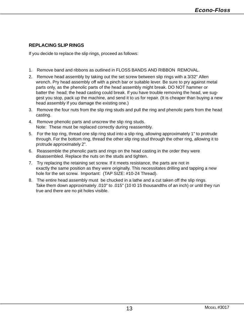
REPLACING SLIP RINGS
If you decide to replace the slip rings, proceed as follows:
1. Remove band and ribbons as outlined in FLOSS BANDS AND RIBBON REMOVAL.
2. Remove head assembly by taking out the set screw between slip rings with a 3/32" Allenwrench. Pry head assembly off with a pinch bar or suitable lever. Be sure to pry against metalparts only, as the phenolic parts of the head assembly might break. DO NOT hammer orbatter the head; the head casting could break. If you have trouble removing the head, we sug-gest you stop, pack up the machine, and send it to us for repair. (It is cheaper than buying a newhead assembly if you damage the existing one.)
3. Remove the four nuts from the slip ring studs and pull the ring and phenolic parts from the headcasting.
4. Remove phenolic parts and unscrew the slip ring studs.Note: These must be replaced correctly during reassembly.
5. For the top ring, thread one slip ring stud into a slip ring, allowing approximately 1" to protrudethrough. For the bottom ring, thread the other slip ring stud through the other ring, allowing it toprotrude approximately 2".
6. Reassemble the phenolic parts and rings on the head casting in the order they weredisassembled. Replace the nuts on the studs and tighten.
7. Try replacing the retaining set screw. If it meets resistance, the parts are not inexactly the same position as they were originally. This necessitates drilling and tapping a newhole for the set screw. Important: (TAP SIZE: #10-24 Thread).
8. The entire head assembly must be chucked in a lathe and a cut taken off the slip rings.Take them down approximately .010" to .015" (10 t0 15 thousandths of an inch) or until they runtrue and there are no pit holes visible.
Econo-Floss
MODEL #301714
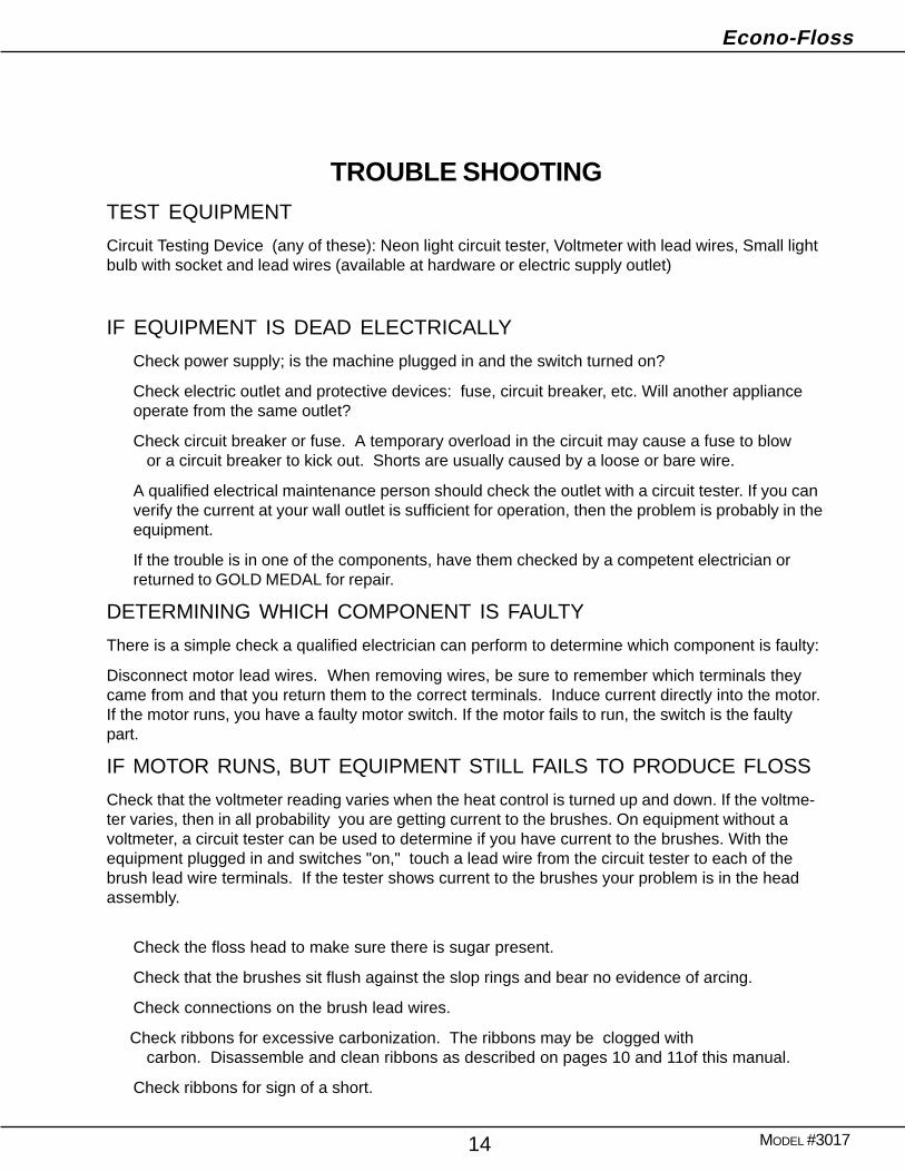
TROUBLE SHOOTINGTEST EQUIPMENT
Circuit Testing Device (any of these): Neon light circuit tester, Voltmeter with lead wires, Small lightbulb with socket and lead wires (available at hardware or electric supply outlet)
IF EQUIPMENT IS DEAD ELECTRICALLY
Check power supply; is the machine plugged in and the switch turned on?
Check electric outlet and protective devices: fuse, circuit breaker, etc. Will another applianceoperate from the same outlet?
Check circuit breaker or fuse. A temporary overload in the circuit may cause a fuse to blowor a circuit breaker to kick out. Shorts are usually caused by a loose or bare wire.
A qualified electrical maintenance person should check the outlet with a circuit tester. If you canverify the current at your wall outlet is sufficient for operation, then the problem is probably in theequipment.
If the trouble is in one of the components, have them checked by a competent electrician orreturned to GOLD MEDAL for repair.
DETERMINING WHICH COMPONENT IS FAULTY
There is a simple check a qualified electrician can perform to determine which component is faulty:
Disconnect motor lead wires. When removing wires, be sure to remember which terminals theycame from and that you return them to the correct terminals. Induce current directly into the motor.If the motor runs, you have a faulty motor switch. If the motor fails to run, the switch is the faultypart.
IF MOTOR RUNS, BUT EQUIPMENT STILL FAILS TO PRODUCE FLOSS
Check that the voltmeter reading varies when the heat control is turned up and down. If the voltme-ter varies, then in all probability you are getting current to the brushes. On equipment without avoltmeter, a circuit tester can be used to determine if you have current to the brushes. With theequipment plugged in and switches "on," touch a lead wire from the circuit tester to each of thebrush lead wire terminals. If the tester shows current to the brushes your problem is in the headassembly.
Check the floss head to make sure there is sugar present.
Check that the brushes sit flush against the slop rings and bear no evidence of arcing.
Check connections on the brush lead wires.
Check ribbons for excessive carbonization. The ribbons may be clogged withcarbon. Disassemble and clean ribbons as described on pages 10 and 11of this manual.
Check ribbons for sign of a short.
Econo-Floss
MODEL #301715
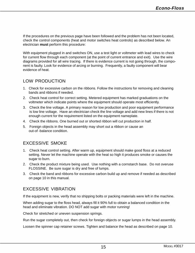
If the procedures on the previous page have been followed and the problem has not been located,check the control components (heat and motor switches heat controls) as described below. Anelectrician must perform this procedure:
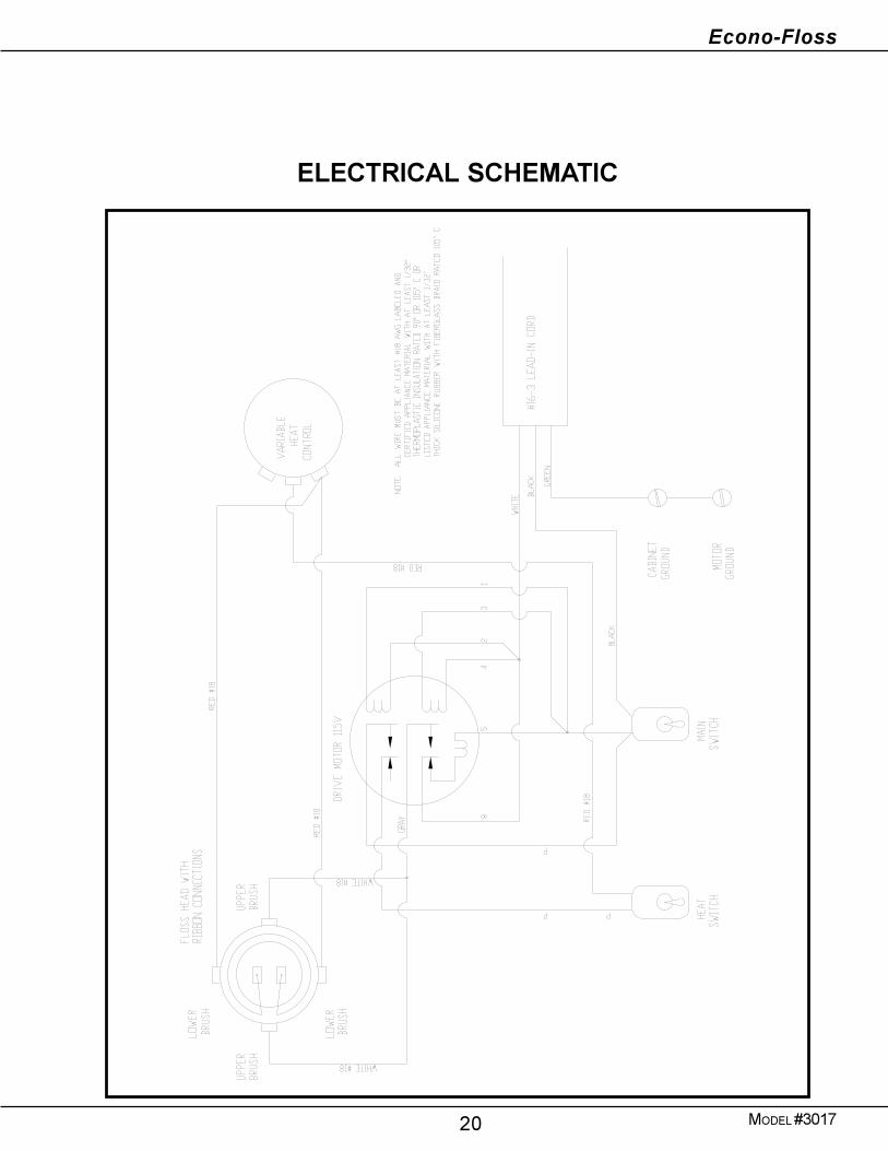
With equipment plugged in and switches ON, use a test light or voltmeter with lead wires to checkfor current flow through each component (at the point of current entrance and exit). Use the wirediagrams provided for all wire tracing. If there is evidence current is not going through, the compo-nent is faulty. Look for evidence of arcing or burning. Frequently, a faulty component will bearevidence of heat.
LOW PRODUCTION
1. Check for excessive carbon on the ribbons. Follow the instructions for removing and cleaningbands and ribbons if needed.
2. Check heat control for correct setting. Metered equipment has marked graduations on thevoltmeter which indicate points where the equipment should operate most efficiently.
3. Check the line voltage. A primary reason for low production and poor equipment performanceis low line voltage. Have an electrician check the line voltage and add new lines if there is notenough current for the requirement listed on the equipment nameplate.
4. Check the ribbons. One burned out or shorted ribbon will cut production in half.
5. Foreign objects in the head assembly may short out a ribbon or cause anout-of -balance condition.
EXCESSIVE SMOKE
1. Check heat control setting. After warm up, equipment should make good floss at a reducedsetting. Never let the machine operate with the heat so high it produces smoke or causes thesugar to burn.
2. Check the product mixture being used. Use nothing with a cornstarch base. Do not overuseFLOSSINE. Be sure sugar is dry and free of lumps.
3. Check the band and ribbons for excessive carbon build up and remove if needed as describedon page 10 in this manual.
EXCESSIVE VIBRATION
If the equipment is new, verify that no shipping bolts or packing materials were left in the machine.
When adding sugar to the floss head, always fill it 90% full to obtain a balanced condition in thehead and eliminate vibration. DO NOT add sugar with motor running!
Check for stretched or uneven suspension springs.
Run the sugar completely out, then check for foreign objects or sugar lumps in the head assembly.
Loosen the spinner cap retainer screws. Tighten and balance the head as described on page 10.
Econo-Floss
MODEL #301716
ORDERING SPARE PARTS
1. Identify the needed part by checking it against the photos, illustrations, and/or the parts list.2. When ordering, please include part number, part name, and quantity needed.3. Please include your model name and machine serial number (located on the machine
nameplate) with your order.4. Address all parts orders to:
Parts DepartmentGold Medal Products Co.
10700 Medallion DriveCincinnati, Ohio 45241-4807
or, place orders at:
(513) 769-7676Fax: (513) 769-8500
Econo-Floss
MODEL #301717
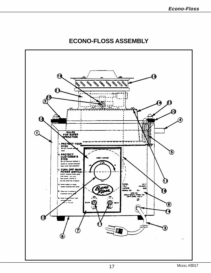
ECONO-FLOSS ASSEMBLY
Econo-Floss
MODEL #301718
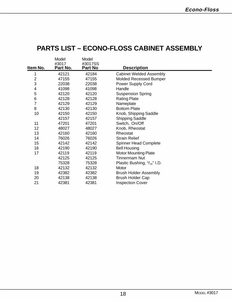
PARTS LIST – ECONO-FLOSS CABINET ASSEMBLYModel Model#3017 #3017SS
Item No. Part No. Part No Description1 42121 42184 Cabinet Welded Assembly2 47155 47155 Molded Recessed Bumper3 22038 22038 Power Supply Cord4 41098 41098 Handle5 42120 42120 Suspension Spring6 42128 42128 Rating Plate7 42129 42129 Nameplate8 42130 42130 Bottom Plate10 42150 42150 Knob, Shipping Saddle
42157 42157 Shipping Saddle11 47201 47201 Switch, On/Off12 48027 48027 Knob, Rheostat13 42160 42160 Rheostat14 76026 76026 Strain Relief15 42142 42142 Spinner Head Complete16 42190 42190 Bell Housing17 42119 42119 Motor Mounting Plate
42125 42125 Tinnermam Nut75328 75328 Plastic Bushing, 5/16" I.D.
18 42132 42132 Motor19 42382 42382 Brush Holder Assembly20 42138 42138 Brush Holder Cap21 42381 42381 Inspection Cover
Econo-Floss
MODEL #301719
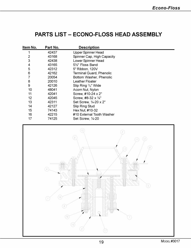
PARTS LIST � ECONO-FLOSS HEAD ASSEMBLY
Item No. Part No. Description1 42437 Upper Spinner Head2 43168 Spinner Cap, High Capacity3 42438 Lower Spinner Head4 43165 5½" Floss Band5 42312 5" Ribbon, 120V6 42162 Terminal Guard, Phenolic7 20054 Bottom Washer, Phenolic8 20010 Leather Floater9 42126 Slip Ring 3/8" Wide10 48041 Acorn Nut, Nylon11 42041 Screw, #10-24 x 2"12 42045 Screw, #8-32 x ¼"13 42311 Set Screw, ¼-20 x 2"14 42127 Slip Ring Stud15 74143 Hex Nut, #10-3216 42215 #10 External Tooth Washer17 74125 Set Screw, ¼-20
Econo-Floss
MODEL #301720
ELECTRICAL SCHEMATIC

WARRANTY
WE WARRANT to the original purchaser the Gold Medal equipment sold by us tobe free from defects in material or workmanship under normal use and service. Ourobligation under this warranty shall be limited to the repair or replacement of anydefective part for a period of six (6) months from the date of sale to the OriginalPurchaser with regard to labor and two (2) years with regard to parts and does notcover damage to the equipment caused by accident, alteration, improper use, volt-age, abuse, or failure to follow instructions.
THIS WARRANTY IS IN LIEU OF ALL OTHER WARRANTIES EXPRESSEDOR IMPLIED, AND OF ALL OTHER OBLIGATIONS OR LIABILITIES ON OURPART, INCLUDING THE IMPLIED WARRANTY OF MERCHANTIBILITY.THERE ARE NO WARRANTIES WHICH EXTEND BEYOND THE DESCRIP-TION ON THE FACE HEREOF. We neither assume, nor authorize any other personto assume for us, any other obligation or liability in connection with the sale of saidGOLD MEDAL equipment or any part thereof.
The term “Original Purchaser” as used in this warranty shall be deemed to mean thatperson, firm, association, or corporation who was billed by the GOLD MEDALPRODUCTS COMPANY, or their authorized distributor for the equipment.
THIS WARRANTY HAS NO EFFECT AND IS VOID UNLESS THE ORIGINALPURCHASER FIRST CALLS GOLD MEDAL PRODUCTS COMPANY AT 1-800-428-2676 TO DISCUSS WITH OUR SERVICE REPRESENTATIVE THE EQUIP-MENT PROBLEM, AND, IF NECESSARY, FOR INSTRUCTIONS CONCERN-ING THE REPAIR OR REPLACEMENT OF PARTS.
NOTE: This equipment is manufactured and sold for commercial use only.
GOLD MEDAL PRODUCTS COMPANY
10700 Medallion Drive
Cincinnati, OH 45241-4807 USA
![Untitled-1 [ ] · PDF fileSaravali, Thane 42131 1, Maharashtra,lNDlA The facility is divided into 4 bays as below : List of Engineering Consultants, Inspection](https://static.fdocuments.us/doc/165x107/5a947ed57f8b9a9c5b8c0d9e/untitled-1-thane-42131-1-maharashtralndla-the-facility-is-divided-into-4-bays.jpg)